8051 instruction set
DESCRIPTION
controllerTRANSCRIPT
1
8051 Instruction Set

2
2
8051 Instruction Set
Introduction
CIP-51 architecture and memory organization review
Addressing modes Register addressing
Direct addressing
Indirect addressing
Immediate constant addressing
Relative addressing
Absolute addressing
Long addressing
Indexed addressing
Instruction types Arithmetic operations
Logical operations
Data transfer instructions
Boolean variable instructions
Program branching instructions
In this lecture we will look at the various addressing modes and the instructions. The 8051 Architecture course would be helpful in understanding some of the concepts presented in this course.
3
3
Introduction
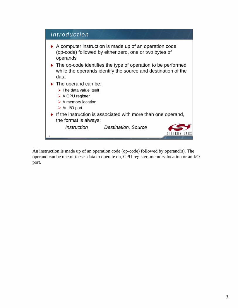
A computer instruction is made up of an operation code (op-code) followed by either zero, one or two bytes of operands
The op-code identifies the type of operation to be performed while the operands identify the source and destination of the data
The operand can be: The data value itself
A CPU register
A memory location
An I/O port
If the instruction is associated with more than one operand, the format is always:
Instruction Destination, Source
An instruction is made up of an operation code (op-code) followed by operand(s). The operand can be one of these- data to operate on, CPU register, memory location or an I/O port.

4
4
CIP-51 Architecture Review
This is the architecture of the C8051. See the 8051 Architecture course for a more in depth look at the core.

5
5
Sample Memory Organization
The memory organization of C8051F93x is similar to that of a standard 8051
Program and data memory share the same address space but are accessed via different instruction types
The memory organisation of C8051F93x is very similar to that of the basic 8051, especially the internal data memory and its layout in terms of register banks, bit-addressable space and location of SFRs. Many more SFRs have been added as the peripheral mix has been expanded.
6
6
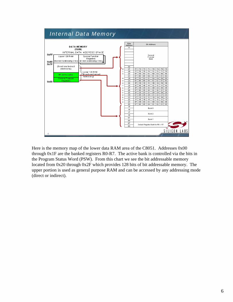
Internal Data Memory
0x00
0x7F0x80
0xFF
Here is the memory map of the lower data RAM area of the C8051. Addresses 0x00 through 0x1F are the banked registers R0-R7. The active bank is controlled via the bits in the Program Status Word (PSW). From this chart we see the bit addressable memory located from 0x20 through 0x2F which provides 128 bits of bit addressable memory. The upper portion is used as general purpose RAM and can be accessed by any addressing mode (direct or indirect).
7
7
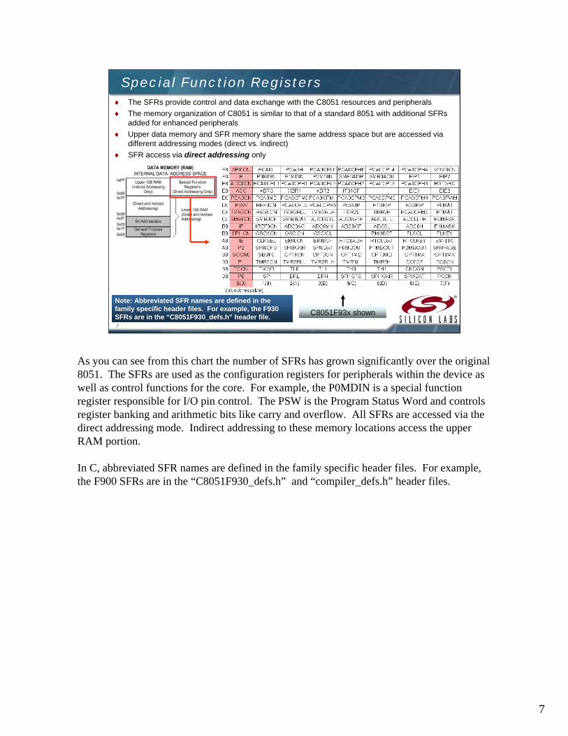
Special Function Registers The SFRs provide control and data exchange with the C8051 resources and peripherals
The memory organization of C8051 is similar to that of a standard 8051 with additional SFRsadded for enhanced peripherals
Upper data memory and SFR memory share the same address space but are accessed via different addressing modes (direct vs. indirect)
SFR access via direct addressing only
C8051F93x shown
Note: Abbreviated SFR names are defined in the family specific header files. For example, the F930 SFRs are in the “C8051F930_defs.h” header file.
As you can see from this chart the number of SFRs has grown significantly over the original 8051. The SFRs are used as the configuration registers for peripherals within the device as well as control functions for the core. For example, the P0MDIN is a special function register responsible for I/O pin control. The PSW is the Program Status Word and controls register banking and arithmetic bits like carry and overflow. All SFRs are accessed via the direct addressing mode. Indirect addressing to these memory locations access the upper RAM portion.
In C, abbreviated SFR names are defined in the family specific header files. For example, the F900 SFRs are in the “C8051F930_defs.h” and “compiler_defs.h” header files.

8
8
Addressing Modes
Eight modes of addressing are available with the C8051
The different addressing modes determine how the operand byte is selected
MOVC A,@A+PCIndexed
LJMP FARLong*
AJMP within 2KAbsolute*
SJMP +127/-128 of PCRelative*
ADD A,#80HImmediate Constant
ADD A,@R0Indirect
MOV 30H,ADirect
MOV A, BRegister
InstructionAddressing Modes
* Related to program branching instructions
There are 8 addressing modes. The addressing mode determines how the operand byte is selected. The direct and indirect addressing modes are used to distinguish between the SFR space and data memory space. The relative instructions are based on the value of the program counter. The absolute instructions operate in the same manner. Indexed instructions use a calculation to generate the address used as part of the instruction.
9
9
Register Addressing
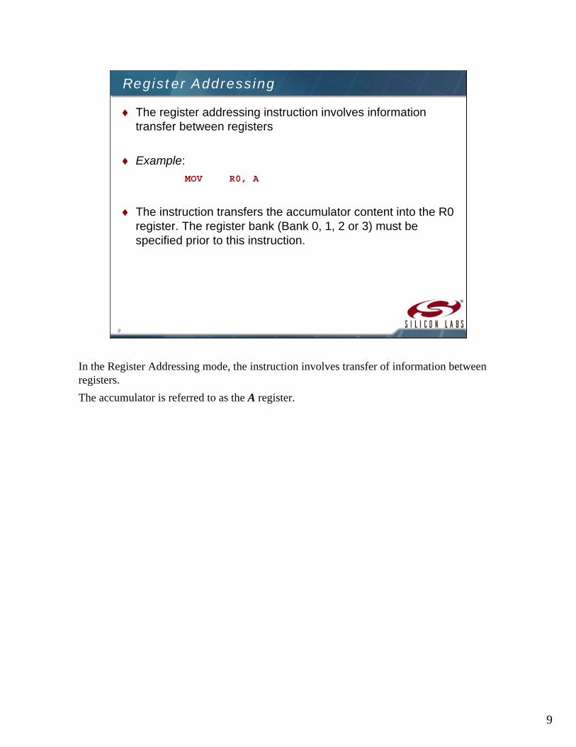
The register addressing instruction involves information transfer between registers
Example:
MOV R0, A
The instruction transfers the accumulator content into the R0 register. The register bank (Bank 0, 1, 2 or 3) must be specified prior to this instruction.
In the Register Addressing mode, the instruction involves transfer of information between registers.
The accumulator is referred to as the A register.
10
10
Direct Addressing
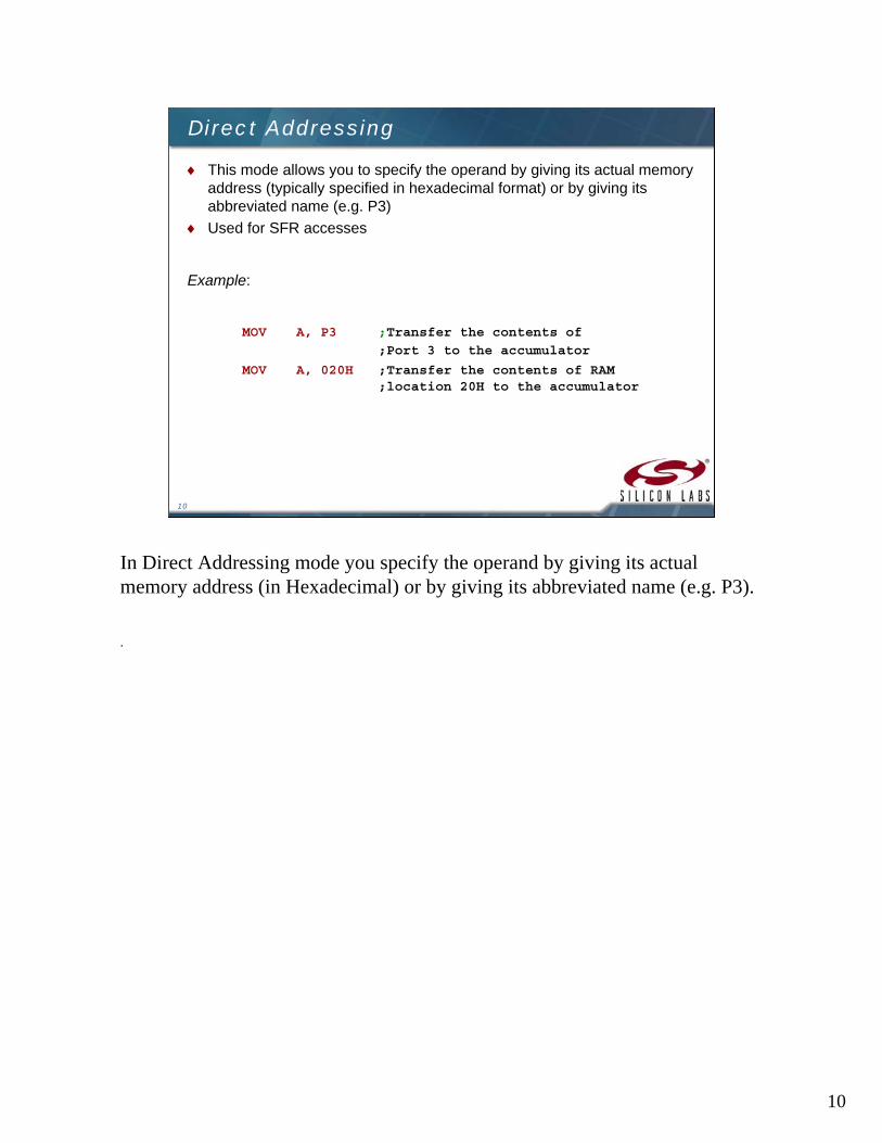
This mode allows you to specify the operand by giving its actual memory address (typically specified in hexadecimal format) or by giving its abbreviated name (e.g. P3)
Used for SFR accesses
Example:
MOV A, P3 ;Transfer the contents of
;Port 3 to the accumulator
MOV A, 020H ;Transfer the contents of RAM ;location 20H to the accumulator
In Direct Addressing mode you specify the operand by giving its actual memory address (in Hexadecimal) or by giving its abbreviated name (e.g. P3).
.
11
11
Indirect Addressing
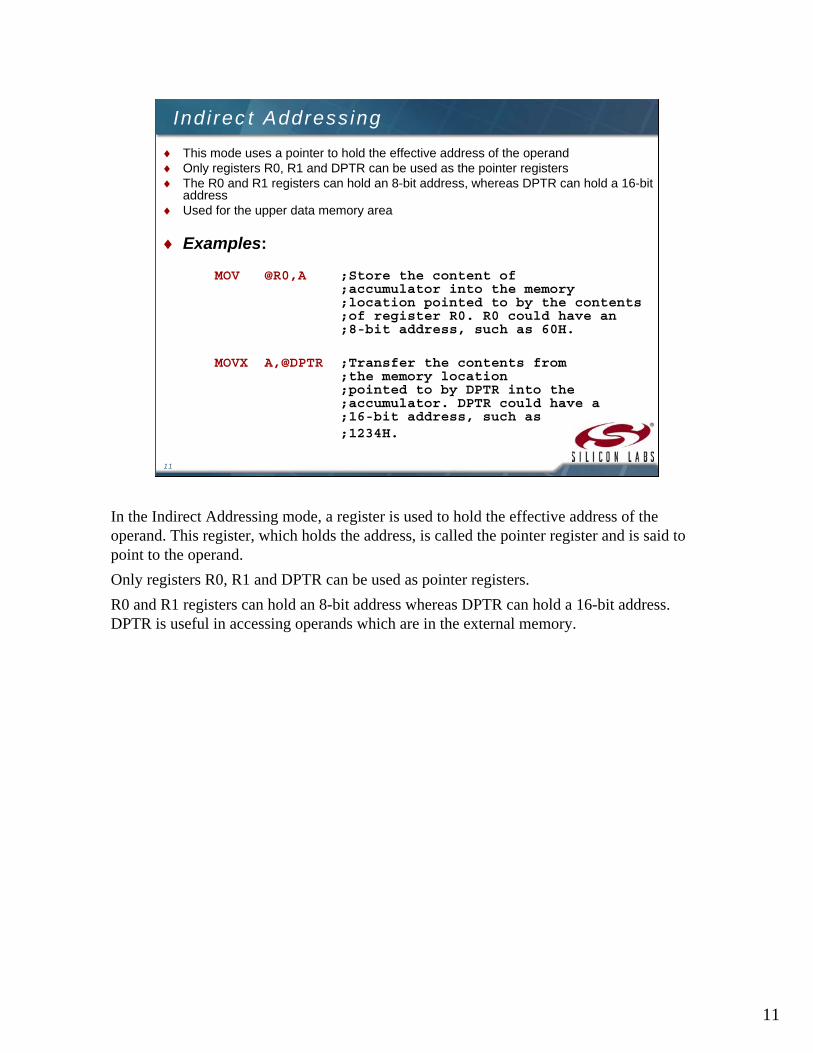
This mode uses a pointer to hold the effective address of the operand Only registers R0, R1 and DPTR can be used as the pointer registers The R0 and R1 registers can hold an 8-bit address, whereas DPTR can hold a 16-bit
address Used for the upper data memory area
Examples:
MOV @R0,A ;Store the content of ;accumulator into the memory ;location pointed to by the contents ;of register R0. R0 could have an ;8-bit address, such as 60H.
MOVX A,@DPTR ;Transfer the contents from ;the memory location ;pointed to by DPTR into the ;accumulator. DPTR could have a;16-bit address, such as ;1234H.
In the Indirect Addressing mode, a register is used to hold the effective address of the operand. This register, which holds the address, is called the pointer register and is said to point to the operand.
Only registers R0, R1 and DPTR can be used as pointer registers.
R0 and R1 registers can hold an 8-bit address whereas DPTR can hold a 16-bit address. DPTR is useful in accessing operands which are in the external memory.
12
12
Immediate Constant Addressing
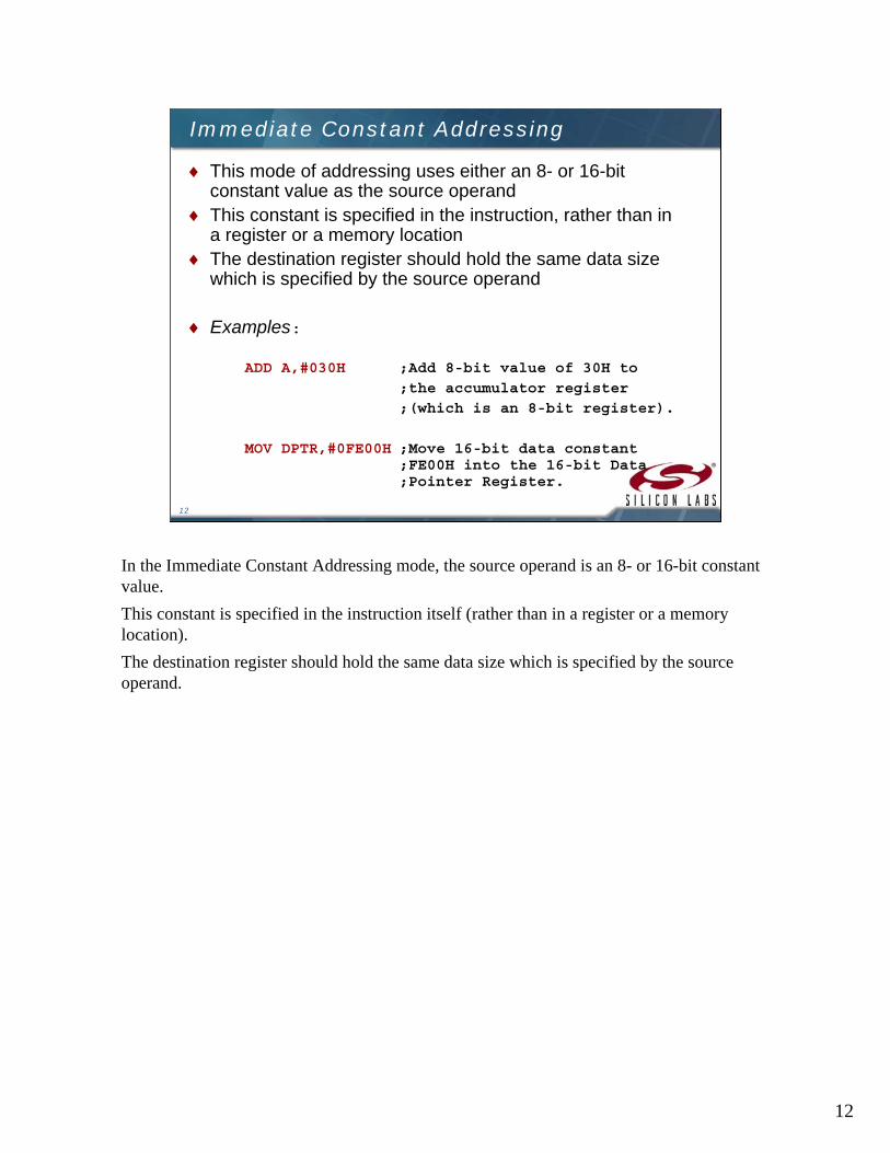
This mode of addressing uses either an 8- or 16-bit constant value as the source operand
This constant is specified in the instruction, rather than in a register or a memory location
The destination register should hold the same data size which is specified by the source operand
Examples:
ADD A,#030H ;Add 8-bit value of 30H to
;the accumulator register
;(which is an 8-bit register).
MOV DPTR,#0FE00H ;Move 16-bit data constant;FE00H into the 16-bit Data ;Pointer Register.
In the Immediate Constant Addressing mode, the source operand is an 8- or 16-bit constant value.
This constant is specified in the instruction itself (rather than in a register or a memory location).
The destination register should hold the same data size which is specified by the source operand.
13
13
Relative Addressing
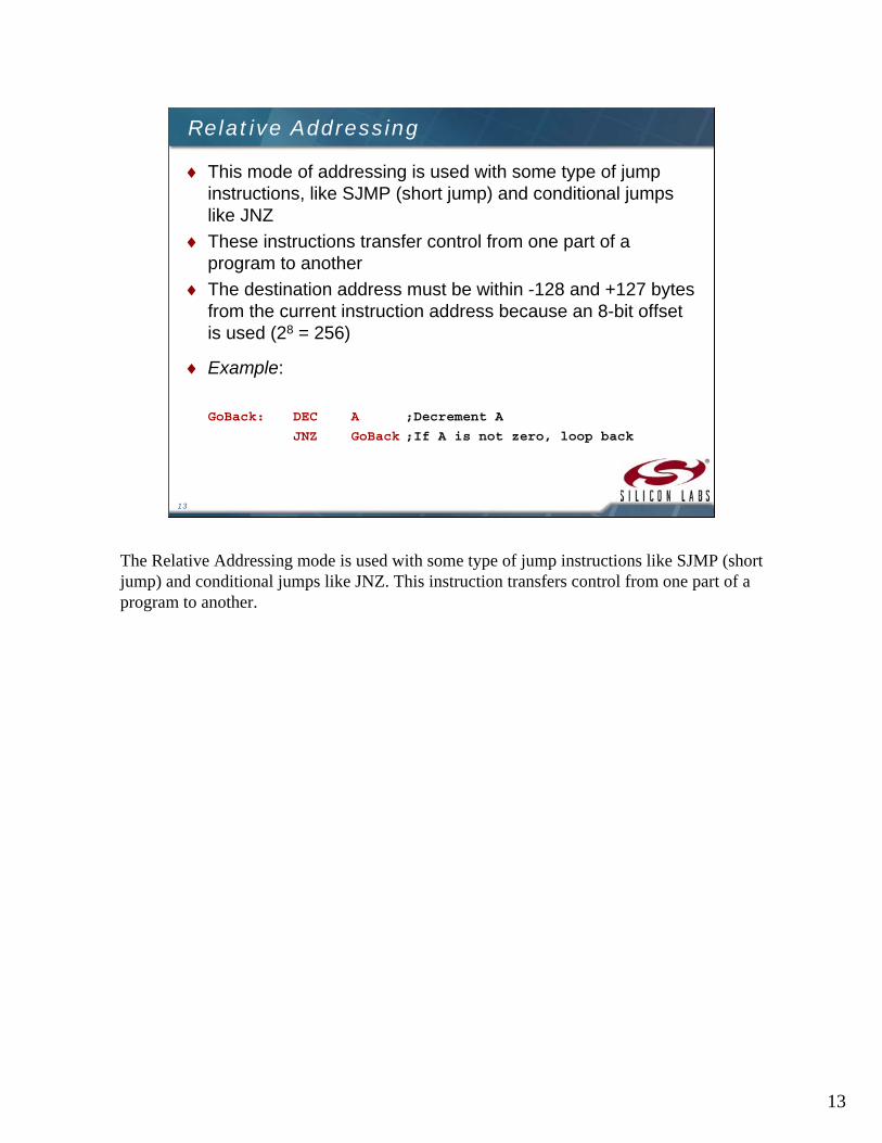
This mode of addressing is used with some type of jump instructions, like SJMP (short jump) and conditional jumps like JNZ
These instructions transfer control from one part of a program to another
The destination address must be within -128 and +127 bytes from the current instruction address because an 8-bit offset is used (28 = 256)
Example:
GoBack: DEC A ;Decrement A
JNZ GoBack ;If A is not zero, loop back
The Relative Addressing mode is used with some type of jump instructions like SJMP (short jump) and conditional jumps like JNZ. This instruction transfers control from one part of a program to another.
14
14
Absolute Addressing
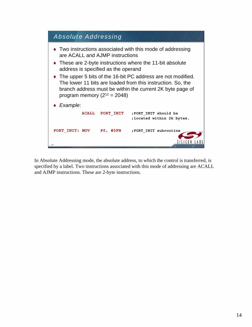
Two instructions associated with this mode of addressing are ACALL and AJMP instructions
These are 2-byte instructions where the 11-bit absolute address is specified as the operand
The upper 5 bits of the 16-bit PC address are not modified. The lower 11 bits are loaded from this instruction. So, the branch address must be within the current 2K byte page of program memory (211 = 2048)
Example:
ACALL PORT_INIT ;PORT_INIT should be ;located within 2k bytes.
PORT_INIT: MOV P0, #0FH ;PORT_INIT subroutine
In Absolute Addressing mode, the absolute address, to which the control is transferred, is specified by a label. Two instructions associated with this mode of addressing are ACALL and AJMP instructions. These are 2-byte instructions.
15
15
Long Addressing
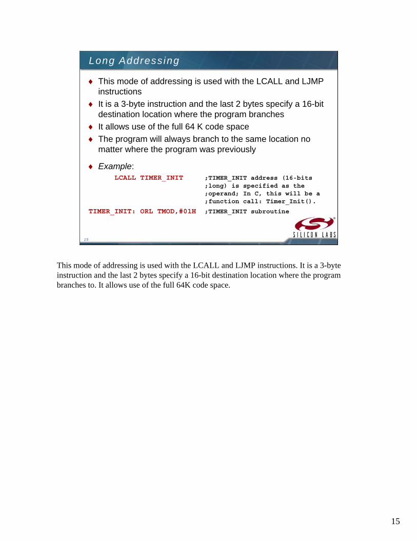
This mode of addressing is used with the LCALL and LJMP instructions
It is a 3-byte instruction and the last 2 bytes specify a 16-bit destination location where the program branches
It allows use of the full 64 K code space
The program will always branch to the same location no matter where the program was previously
Example:LCALL TIMER_INIT ;TIMER_INIT address (16-bits
;long) is specified as the ;operand; In C, this will be a ;function call: Timer_Init().
TIMER_INIT: ORL TMOD,#01H ;TIMER_INIT subroutine
This mode of addressing is used with the LCALL and LJMP instructions. It is a 3-byte instruction and the last 2 bytes specify a 16-bit destination location where the program branches to. It allows use of the full 64K code space.
16
16
Indexed Addressing
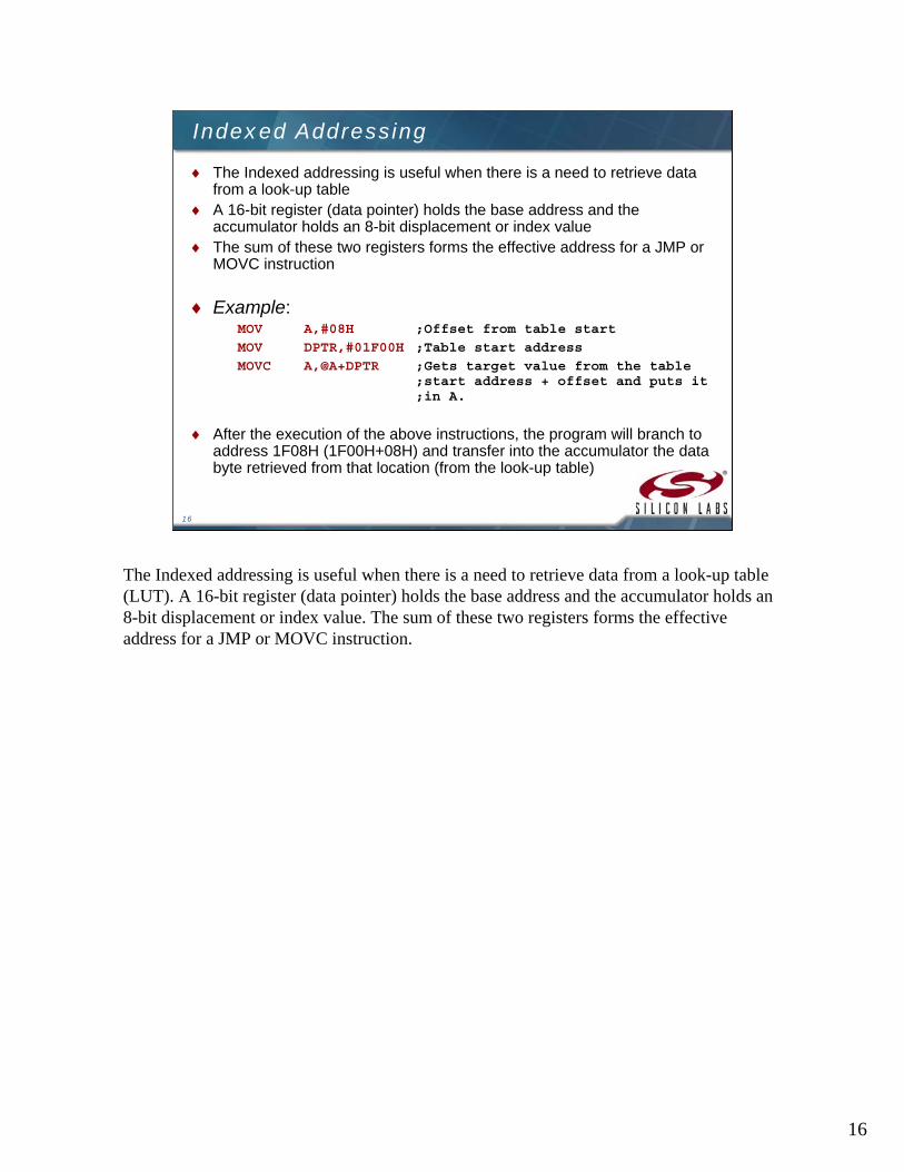
The Indexed addressing is useful when there is a need to retrieve data from a look-up table
A 16-bit register (data pointer) holds the base address and the accumulator holds an 8-bit displacement or index value
The sum of these two registers forms the effective address for a JMP or MOVC instruction
Example:MOV A,#08H ;Offset from table start
MOV DPTR,#01F00H ;Table start address
MOVC A,@A+DPTR ;Gets target value from the table ;start address + offset and puts it ;in A.
After the execution of the above instructions, the program will branch to address 1F08H (1F00H+08H) and transfer into the accumulator the data byte retrieved from that location (from the look-up table)
The Indexed addressing is useful when there is a need to retrieve data from a look-up table (LUT). A 16-bit register (data pointer) holds the base address and the accumulator holds an 8-bit displacement or index value. The sum of these two registers forms the effective address for a JMP or MOVC instruction.
17
17
Instruction Types
The C8051 instructions are divided into five functional groups:
Arithmetic operations
Logical operations
Data transfer operations
Boolean variable operations
Program branching operations
The C8051F instructions are divided into five functional groups. We will discuss each group separately.
18
18
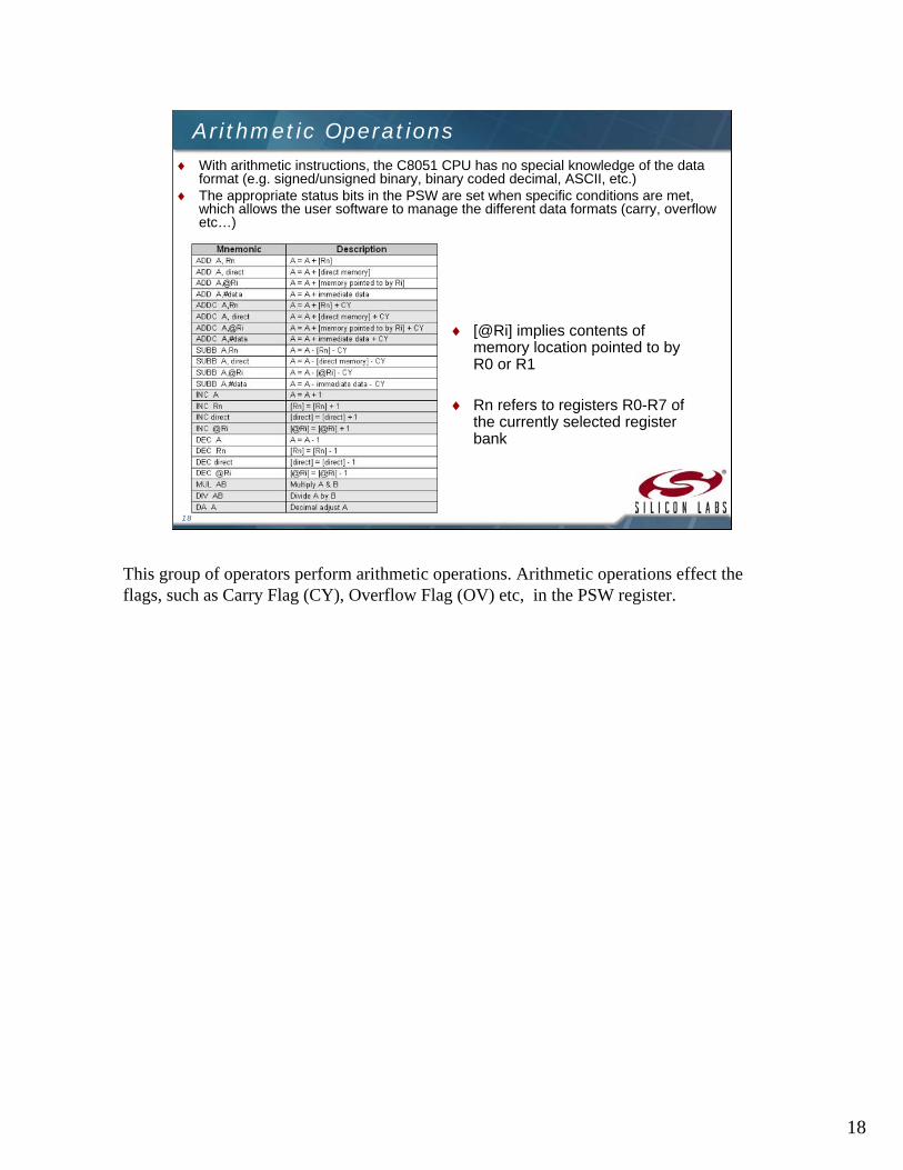
Arithmetic Operations With arithmetic instructions, the C8051 CPU has no special knowledge of the data
format (e.g. signed/unsigned binary, binary coded decimal, ASCII, etc.) The appropriate status bits in the PSW are set when specific conditions are met,
which allows the user software to manage the different data formats (carry, overflow etc…)
[@Ri] implies contents of memory location pointed to by R0 or R1
Rn refers to registers R0-R7 of the currently selected register bank
This group of operators perform arithmetic operations. Arithmetic operations effect the flags, such as Carry Flag (CY), Overflow Flag (OV) etc, in the PSW register.

19
19
Logical Operations
Logical instructions perform Boolean operations (AND, OR, XOR, and NOT) on data bytes on a bit-by-bitbasis
Examples:
ANL A, #02H ;Mask bit 1
ORL TCON, A ;TCON=TCON OR A
Logical instructions perform standard Boolean operations such as AND, OR, XOR, NOT (compliment). Other logical operations are clear accumulator, rotate accumulator left and right, and swap nibbles in accumulator.

20
20
Data Transfer Instructions Data transfer instructions can be
used to transfer data between an internal RAM location and an SFR location without going through the accumulator
It is also possible to transfer data between the internal and external RAM by using indirect addressing
The upper 128 bytes of data RAM are accessed only by indirect addressing and the SFRs are accessed only by direct addressing
Exchange low order digitsXCHD A,@Ri
A = [@Rn], [@Rn] = AXCH A, @Ri
A = [direct], [direct] = AXCH A, direct
A = [Rn], [Rn] = AXCH A,Rn
Pop from stackPOP direct
Push into stackPUSH direct
External[@DPTR] = AMOVX @DPTR,A
External[@Ri] = AMOVX @Ri, A
A = Data byte from external ram [@DPTR]MOVX A,@DPTR
A = Data byte from external ram [@Ri]MOVX A,@Ri
A = Code byte from [@A+PC]MOVC A,@A+PC
A = Code byte from [@A+DPTR]MOVC A,@A+DPTR
[DPTR] = immediate dataMOV DPTR, #data 16
[@Ri] = immediate dataMOV @Ri, #data
[@Ri] = [direct]MOV @Ri, direct
DescriptionMnemonic
Data transfer instructions are used to transfer data between an internal RAM location and SFR location without going through the accumulator. Data can also be transferred between the internal and external RAM by using indirect addressing.

21
21
Boolean Variable Instructions
The C8051 processor can perform single bit operations
The operations include set, clear, and, or and complement instructions
Also included are bit–level moves or conditional jump instructions
All bit accesses use direct addressing
Examples:
SETB TR0 ;Start Timer0.
POLL: JNB TR0, POLL ;Wait until timer overflows.
if specified bit set then clear it and jump
JBC bit,rel
Jump if specified bit not setJNB bit,rel
Jump if specified bit setJB bit,rel
Jump if C not setJNC rel
Jump if C setJC rel
MOV C to bitMOV bit,C
MOV bit to CMOV C,bit
OR NOT bit with CORL C,/bit
OR bit with CORL C,bit
AND NOT bit with CANL C,/bit
AND bit with CANL C,bit
Complement direct bitCPL bit
Complement cCPL C
Set direct bitSETB bit
Set CSETB C
Clear direct bitCLR bit
Clear CCLR C
DescriptionMnemonic
The Boolean Variable operations include set, clear, as well as and, or and complementinstructions. Also included are bit–level moves or conditional jump instructions. All bit accesses use direct addressing.
22
22
Program Branching Instructions
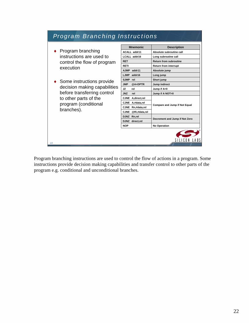
Program branching instructions are used to control the flow of program execution
Some instructions provide decision making capabilities before transferring control to other parts of the program (conditional branches).
No OperationNOP
DJNZ direct,relDecrement and Jump if Not Zero
DJNZ Rn,rel
CJNE @Ri,#data,rel
CJNE Rn,#data,rel
CJNE A,#data,relCompare and Jump if Not Equal
CJNE A,direct,rel
Jump if A NOT=0JNZ rel
Jump if A=0JZ rel
Jump indirectJMP @A+DPTR
Short jumpSJMP rel
Long jumpLJMP addr16
Absolute jumpAJMP addr11
Return from interruptRETI
Return from subroutineRET
Long subroutine callLCALL addr16
Absolute subroutine callACALL addr11
DescriptionMnemonic
Program branching instructions are used to control the flow of actions in a program. Some instructions provide decision making capabilities and transfer control to other parts of the program e.g. conditional and unconditional branches.

23

24
24
Arithmetic Operations
[@Ri] implies contents of memory location pointed to by R0 or R1
Rn refers to registers R0-R7 of the currently selected register bank
The arithmetic operations are – addition, subtraction, increment, decrement, multiplication and division. The operations use different addressing modes discussed earlier.
25
25
ADD A,<source-byte> ADDC A,<source-byte>
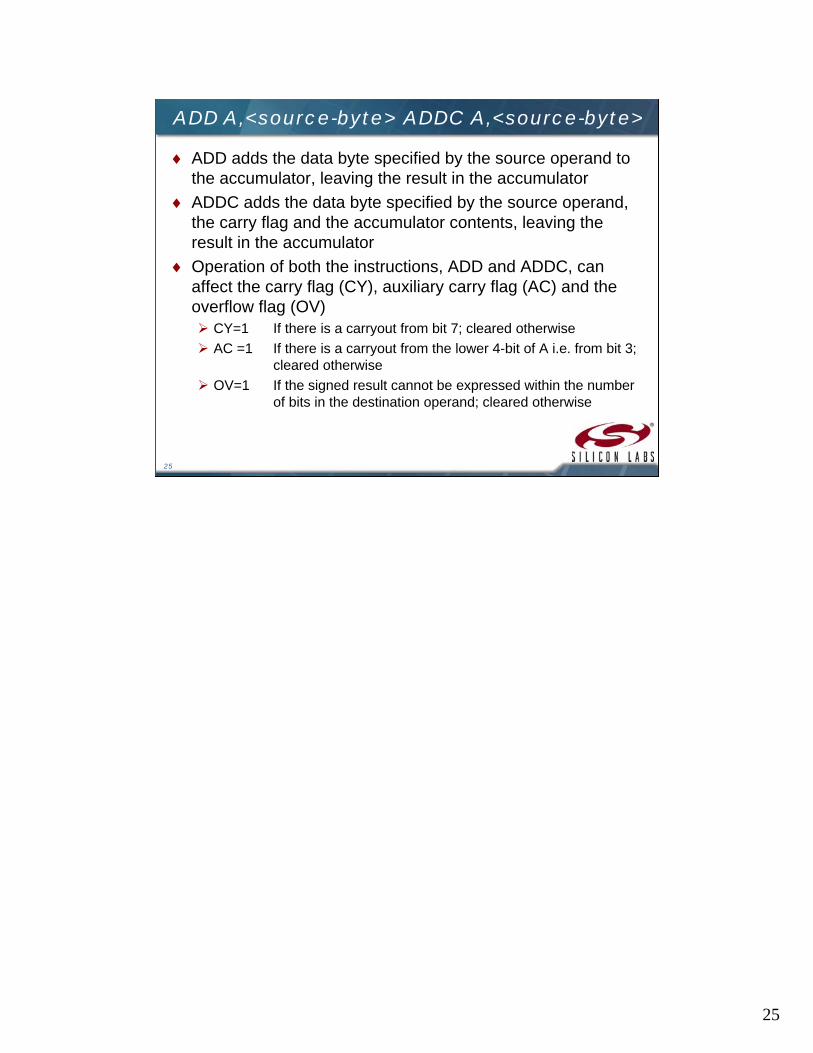
ADD adds the data byte specified by the source operand to the accumulator, leaving the result in the accumulator
ADDC adds the data byte specified by the source operand, the carry flag and the accumulator contents, leaving the result in the accumulator
Operation of both the instructions, ADD and ADDC, can affect the carry flag (CY), auxiliary carry flag (AC) and the overflow flag (OV) CY=1 If there is a carryout from bit 7; cleared otherwise
AC =1 If there is a carryout from the lower 4-bit of A i.e. from bit 3; cleared otherwise
OV=1 If the signed result cannot be expressed within the number of bits in the destination operand; cleared otherwise

26
26
SUBB A,<source-byte>
SUBB subtracts the specified data byte and the carry flag together from the accumulator, leaving the result in the accumulatorCY=1 If a borrow is needed for bit 7; cleared otherwise
AC =1 If a borrow is needed for bit 3, cleared otherwise
OV=1 If a borrow is needed into bit 6, but not into bit 7, or into bit 7, but not into bit 6.
Example:
The accumulator holds 0C1H (11000001B), Register1 holds 40H (01000000B) and the CY=1.The instruction,
SUBB A, R1
gives the value 70H (01110000B) in the accumulator, with the CY=0 and AC=0 but OV=1
27
27
INC <byte>
Increments the data variable by 1. The instruction is used in register, direct or register direct addressing modes
Example:
INC 6FH
If the internal RAM location 6FH contains 30H, then the instruction increments this value, leaving 31H in location 6FH
Example:
MOV R1, #5EINC R1INC @R1
If R1=5E (01011110) and internal RAM location 5FH contains 20H, the instructions will result in R1=5FH and internal RAM location 5FH to increment by one to 21H
28
28
DEC <byte>
The data variable is decremented by 1
The instruction is used in accumulator, register, direct or register direct addressing modes
A data of value 00H underflows to FFH after the operation
No flags are affected
29
29
INC DPTR
Increments the 16-bit data pointer by 1
DPTR is the only 16-bit register that can be incremented
The instruction adds one to the contents of DPTR directly
30
30
MUL AB
Multiplies A & B and the 16-bit result stored in [B15-8], [A7-0]
Multiplies the unsigned 8-bit integers in the accumulator and the B register
The Low order byte of the 16-bit product will go to the accumulator and the High order byte will go to the B register
If the product is greater than 255 (FFH), the overflow flag is set; otherwise it is cleared. The carry flag is always cleared.
If ACC=85 (55H) and B=23 (17H), the instruction gives the product 1955 (07A3H), so B is now 07H and the accumulator is A3H. The overflow flag is set and the carry flag is cleared.
31
31
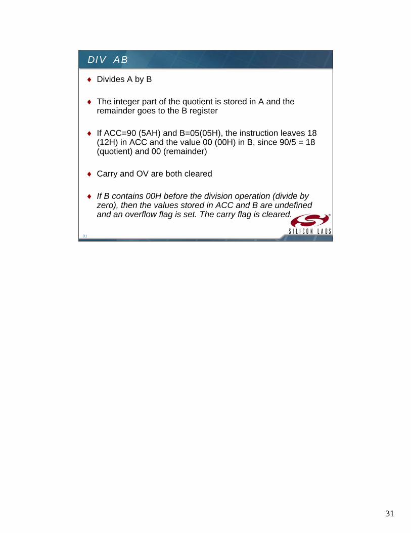
DIV AB
Divides A by B
The integer part of the quotient is stored in A and the remainder goes to the B register
If ACC=90 (5AH) and B=05(05H), the instruction leaves 18 (12H) in ACC and the value 00 (00H) in B, since 90/5 = 18 (quotient) and 00 (remainder)
Carry and OV are both cleared
If B contains 00H before the division operation (divide by zero), then the values stored in ACC and B are undefined and an overflow flag is set. The carry flag is cleared.
32
32
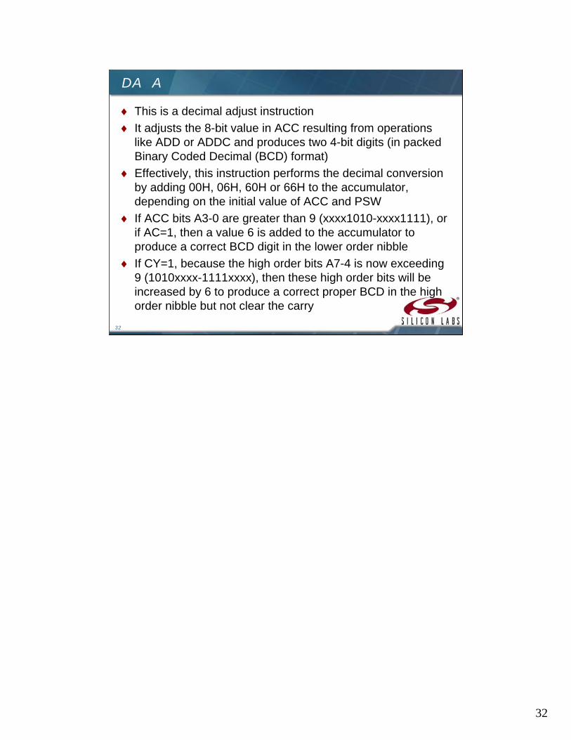
DA A
This is a decimal adjust instruction
It adjusts the 8-bit value in ACC resulting from operations like ADD or ADDC and produces two 4-bit digits (in packed Binary Coded Decimal (BCD) format)
Effectively, this instruction performs the decimal conversion by adding 00H, 06H, 60H or 66H to the accumulator, depending on the initial value of ACC and PSW
If ACC bits A3-0 are greater than 9 (xxxx1010-xxxx1111), or if AC=1, then a value 6 is added to the accumulator to produce a correct BCD digit in the lower order nibble
If CY=1, because the high order bits A7-4 is now exceeding 9 (1010xxxx-1111xxxx), then these high order bits will be increased by 6 to produce a correct proper BCD in the high order nibble but not clear the carry
33
33
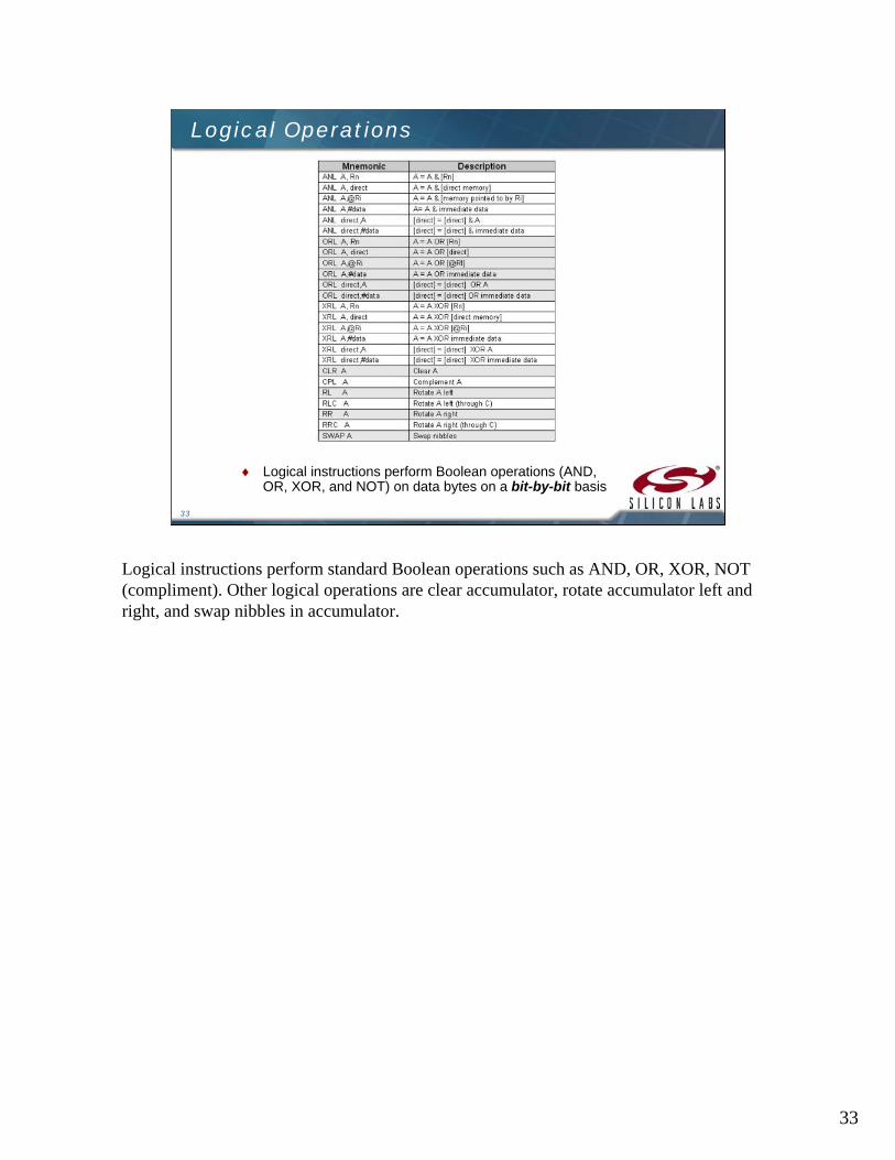
Logical Operations
Logical instructions perform Boolean operations (AND, OR, XOR, and NOT) on data bytes on a bit-by-bit basis
Logical instructions perform standard Boolean operations such as AND, OR, XOR, NOT (compliment). Other logical operations are clear accumulator, rotate accumulator left and right, and swap nibbles in accumulator.
34
34
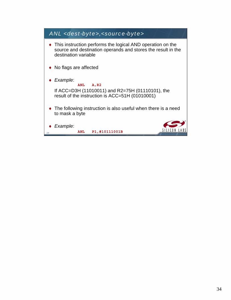
ANL <dest-byte>,<source-byte>
This instruction performs the logical AND operation on the source and destination operands and stores the result in the destination variable
No flags are affected
Example:ANL A,R2
If ACC=D3H (11010011) and R2=75H (01110101), the result of the instruction is ACC=51H (01010001)
The following instruction is also useful when there is a need to mask a byte
Example:ANL P1,#10111001B

35
35
ORL <dest-byte>,<source-byte>
This instruction performs the logical OR operation on the source and destination operands and stores the result in the destination variable
No flags are affected
Example:ORL A,R2
If ACC=D3H (11010011) and R2=75H (01110101), the result of the instruction is ACC=F7H (11110111)
Example:ORL P1,#11000010B
This instruction sets bits 7, 6, and 1 of output Port 1

36
36
XRL <dest-byte>,<source-byte>
This instruction performs the logical XOR (Exclusive OR) operation on the source and destination operands and stores the result in the destination variable
No flags are affected
Example:XRL A,R0
If ACC=C3H (11000011) and R0=AAH (10101010), then the instruction results in ACC=69H (01101001)
Example:XRL P1,#00110001
This instruction complements bits 5, 4, and 0 of output Port 1

37
37
CLR A and CPL A
CLR A This instruction clears the accumulator (all bits set to 0) No flags are affected If ACC=C3H, then the instruction results in ACC=00H
CPL A This instruction logically complements each bit of the
accumulator (one’s complement)
No flags are affected
If ACC=C3H (11000011), then the instruction results in ACC=3CH (00111100)
38
38
RL A
The 8 bits in the accumulator are rotated one bit to the left. Bit 7 is rotated into the bit 0 position.
No flags are affected
If ACC=C3H (11000011), then the instruction results in ACC=87H (10000111) with the carry unaffected
39
39
RLC A
The instruction rotates the accumulator contents one bit to the left through the carry flag
Bit 7 of the accumulator will move into carry flag and the original value of the carry flag will move into the Bit 0 position
No other flags are affected
If ACC=C3H (11000011), and the carry flag is 1, the instruction results in ACC=87H (10000111) with the carry flag set

40
40
RR A
The 8 bits in the accumulator are rotated one bit to the right. Bit 0 is rotated into the bit 7 position.
No flags are affected
If ACC=C3H (11000011), then the instruction results in ACC=E1H (11100001) with the carry unaffected

41
41
RRC A
The instruction rotates the accumulator contents one bit to the right through the carry flag
The original value of carry flag will move into Bit 7 of the accumulator and Bit 0 rotated into carry flag
No other flags are affected
If ACC=C3H (11000011), and the carry flag is 0, the instruction results in ACC=61H (01100001) with the carry flag set
42
42
SWAP A
This instruction interchanges the low order 4-bit nibbles (A3-0) with the high order 4-bit nibbles (A7-4) of the ACC
The operation can also be thought of as a 4-bit rotate instruction
No flags are affected
If ACC=C3H (11000011), then the instruction leaves ACC=3CH (00111100)
43
43
Data Transfer Instructions
Data transfer instructions can be used to transfer data between an internal RAM location and SFR location without going through the accumulator
It is possible to transfer data between the internal and external RAM by using indirect addressing
The upper 128 bytes of data RAM are accessed only by indirect addressing and the SFRs are accessed only by direct addressing
Data transfer instructions are used to transfer data between an internal RAM location and SFR location without going through the accumulator. Data can also be transferred between the internal and external RAM by using indirect addressing.
44
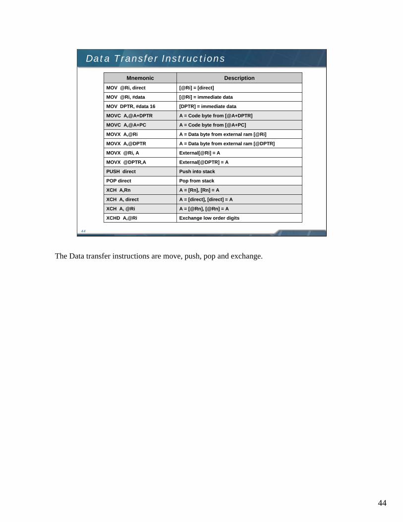
44
Data Transfer Instructions
Exchange low order digitsXCHD A,@Ri
A = [@Rn], [@Rn] = AXCH A, @Ri
A = [direct], [direct] = AXCH A, direct
A = [Rn], [Rn] = AXCH A,Rn
Pop from stackPOP direct
Push into stackPUSH direct
External[@DPTR] = AMOVX @DPTR,A
External[@Ri] = AMOVX @Ri, A
A = Data byte from external ram [@DPTR]MOVX A,@DPTR
A = Data byte from external ram [@Ri]MOVX A,@Ri
A = Code byte from [@A+PC]MOVC A,@A+PC
A = Code byte from [@A+DPTR]MOVC A,@A+DPTR
[DPTR] = immediate dataMOV DPTR, #data 16
[@Ri] = immediate dataMOV @Ri, #data
[@Ri] = [direct]MOV @Ri, direct
DescriptionMnemonic
The Data transfer instructions are move, push, pop and exchange.

45
45
MOV <dest-byte>,<source-byte>
This instruction moves the source byte into the destination location
The source byte is not affected, neither are any other registers or flags
Example:
MOV R1,#60 ;R1=60H
MOV A,@R1 ;A=[60H]
MOV R2,#61 ;R2=61H
ADD A,@R2 ;A=A+[61H]
MOV R7,A ;R7=A
If internal RAM locations 60H=10H, and 61H=20H, then after the operations of the above instructions R7=A=30H. The data contents of memory locations 60H and 61H remain intact.

46
46
MOV DPTR, #data 16
This instruction loads the data pointer with the 16-bit constant and no flags are affected
Example:
MOV DPTR,#1032
This instruction loads the value 1032H into the data pointer, i.e. DPH=10H and DPL=32H.
47
47
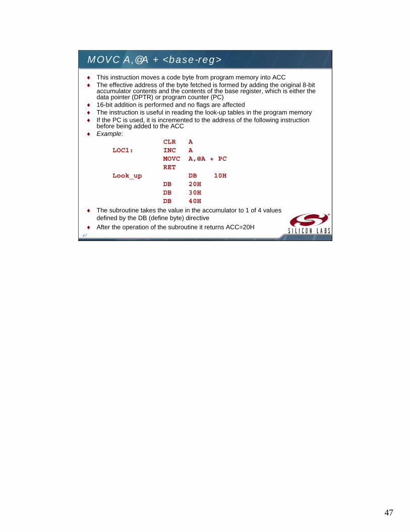
MOVC A,@A + <base-reg>
This instruction moves a code byte from program memory into ACC The effective address of the byte fetched is formed by adding the original 8-bit
accumulator contents and the contents of the base register, which is either the data pointer (DPTR) or program counter (PC)
16-bit addition is performed and no flags are affected The instruction is useful in reading the look-up tables in the program memory If the PC is used, it is incremented to the address of the following instruction
before being added to the ACC Example:
CLR ALOC1: INC A
MOVC A,@A + PCRET
Look_up DB 10HDB 20HDB 30HDB 40H
The subroutine takes the value in the accumulator to 1 of 4 values defined by the DB (define byte) directive
After the operation of the subroutine it returns ACC=20H
48
48
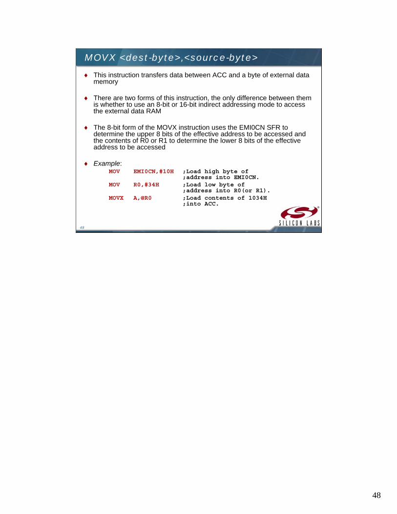
MOVX <dest-byte>,<source-byte>
This instruction transfers data between ACC and a byte of external data memory
There are two forms of this instruction, the only difference between them is whether to use an 8-bit or 16-bit indirect addressing mode to access the external data RAM
The 8-bit form of the MOVX instruction uses the EMI0CN SFR to determine the upper 8 bits of the effective address to be accessed and the contents of R0 or R1 to determine the lower 8 bits of the effective address to be accessed
Example:MOV EMI0CN,#10H ;Load high byte of
;address into EMI0CN.MOV R0,#34H ;Load low byte of
;address into R0(or R1).MOVX A,@R0 ;Load contents of 1034H
;into ACC.
49
49
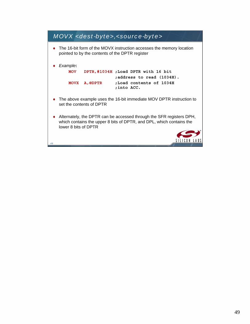
MOVX <dest-byte>,<source-byte>
The 16-bit form of the MOVX instruction accesses the memory location pointed to by the contents of the DPTR register
Example:MOV DPTR,#1034H ;Load DPTR with 16 bit
;address to read (1034H).
MOVX A,@DPTR ;Load contents of 1034H ;into ACC.
The above example uses the 16-bit immediate MOV DPTR instruction to set the contents of DPTR
Alternately, the DPTR can be accessed through the SFR registers DPH, which contains the upper 8 bits of DPTR, and DPL, which contains the lower 8 bits of DPTR
50
50
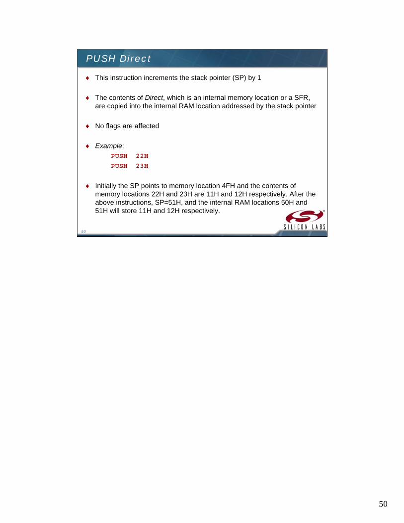
PUSH Direct
This instruction increments the stack pointer (SP) by 1
The contents of Direct, which is an internal memory location or a SFR, are copied into the internal RAM location addressed by the stack pointer
No flags are affected
Example:
PUSH 22H
PUSH 23H
Initially the SP points to memory location 4FH and the contents of memory locations 22H and 23H are 11H and 12H respectively. After the above instructions, SP=51H, and the internal RAM locations 50H and 51H will store 11H and 12H respectively.

51
51
POP Direct
This instruction reads the contents of the internal RAM locationaddressed by the stack pointer (SP) and decrements the stack pointer by 1. The data read is then transferred to the Direct address which is an internal memory or a SFR. No flags are affected.
Example:POP DPHPOP DPL
If SP=51H originally and internal RAM locations 4FH, 50H and 51Hcontain the values 30H, 11H and 12H respectively, the instructions above leave SP=4FH and DPTR=1211H
POP SP If the above line of instruction follows, then SP=30H. In this case, SP is
decremented to 4EH before being loaded with the value popped (30H)

52
52
XCH A,<byte>
This instruction swaps the contents of ACC with the contents of the indicated data byte
Example:XCH A,@R0
Suppose R0=2EH, ACC=F3H (11110011) and internal RAM location 2EH=76H (01110110). The result of the above instruction leaves RAM location 2EH=F3H and ACC=76H.

53
53
XCHD A,@Ri
This instruction exchanges the low order nibble of ACC (bits 0-3), with that of the internal RAM location pointed to by Riregister
The high order nibbles (bits 7-4) of both the registers remain the same
No flags are affected
Example:XCHD A,@R0
If R0=2EH, ACC=76H (01110110) and internal RAM location 2EH=F3H (11110011), the result of the instruction leaves RAM location 2EH=F6H (11110110) and ACC=73H (01110011)

54
54
Boolean Variable Instructions
The C8051 processor can perform single bit operations
The operations include set, clear, as well as and, or and complement instructions
Also included are bit–level moves or conditional jump instructions
All bit accesses use direct addressing
if specified bit set then clear it and jump
JBC bit,rel
Jump if specified bit not setJNB bit,rel
Jump if specified bit setJB bit,rel
Jump if C not setJNC rel
Jump if C setJC rel
MOV C to bitMOV bit,C
MOV bit to CMOV C,bit
OR NOT bit with CORL C,/bit
OR bit with CORL C,bit
AND NOT bit with CANL C,/bit
AND bit with CANL C,bit
Complement direct bitCPL bit
Complement cCPL C
Set direct bitSETB bit
Set CSETB C
Clear direct bitCLR bit
Clear CCLR C
DescriptionMnemonic
The Boolean Variable operations include set, clear, as well as and, or and complementinstructions. Also included are bit–level moves or conditional jump instructions. All bit accesses use direct addressing.

55
55
CLR <bit>
This operation clears (reset to 0) the specified bit indicated in the instruction
No other flags are affected
CLR instruction can operate on the carry flag or any directly-addressable bit
Example:CLR P2.7
If Port 2 has been previously written with DCH (11011100), then the operation leaves the port set to 5CH (01011100)

56
56
SETB <bit>
This operation sets the specified bit to 1
SETB instruction can operate on the carry flag or any directly-addressable bit
No other flags are affected
Example:SETB C
SETB P2.0
If the carry flag is cleared and the output Port 2 has the value of 24H (00100100), then the result of the instructions sets the carry flag to 1 and changes the Port 2 value to 25H (00100101)

57
57
CPL <bit>
This operation complements the bit indicated by the operand
No other flags are affected
CPL instruction can operate on the carry flag or any directly-addressable bit
Example:CPL P2.1
CPL P2.2
If Port 2 has the value of 53H (01010011) before the start of the instructions, then after the execution of the instructions it leaves the port set to 55H (01010101)

58
58
ANL C, <source-bit>
This instruction ANDs the bit addressed with the carry bit and stores the result in the carry bit itself
If the source bit is a logical 0, then the instruction clears the carry flag; else the carry flag is left in its original value
If a slash (/) is used in the source operand bit, it means that the logical complement of the addressed source bit is used, but the source bit itself is not affected
No other flags are affected
Example:MOV C,P2.0 ;Load C with input pin
;state of P2.0.ANL C,P2.7 ;AND carry flag with bit 7 of P2MOV P2.1,C ;Move C to bit 1 of Port 2ANL C,/OV ;AND with inverse of OV flag
If P2.0=1, P2.7=0 and OV=0 initially, then after the above instructions, P2.1=0, CY=0 and the OV remains unchanged, i.e. OV=0
59
59
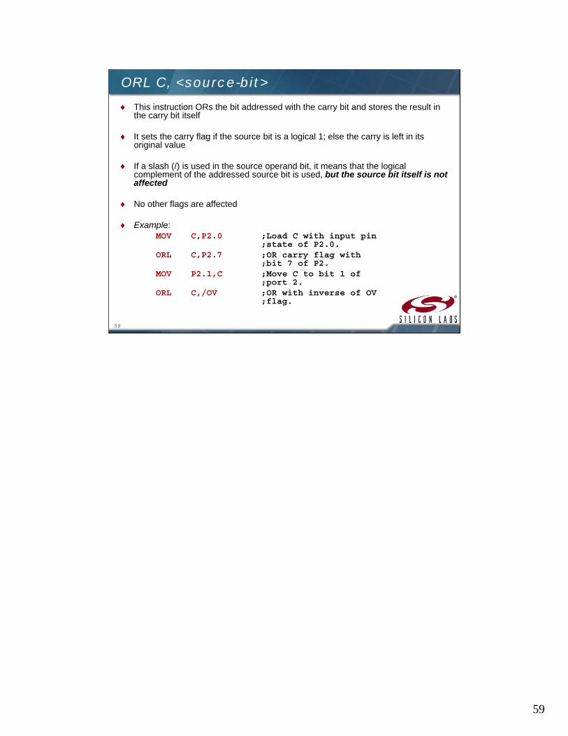
ORL C, <source-bit>
This instruction ORs the bit addressed with the carry bit and stores the result in the carry bit itself
It sets the carry flag if the source bit is a logical 1; else the carry is left in its original value
If a slash (/) is used in the source operand bit, it means that the logical complement of the addressed source bit is used, but the source bit itself is not affected
No other flags are affected
Example:MOV C,P2.0 ;Load C with input pin
;state of P2.0.ORL C,P2.7 ;OR carry flag with
;bit 7 of P2.MOV P2.1,C ;Move C to bit 1 of
;port 2.ORL C,/OV ;OR with inverse of OV
;flag.

60
60
MOV <dest-bit>,<source-bit>
The instruction loads the value of source operand bit into the destination operand bit
One of the operands must be the carry flag; the other may be any directly-addressable bit
No other register or flag is affected
Example:
MOV P2.3,C
MOV C,P3.3
MOV P2.0,C
If P2=C5H (11000101), P3.3=0 and CY=1 initially, then after the above instructions, P2=CCH (11001100) and CY=0

61
61
JC rel
This instruction branches to the address, indicated by the label, if the carry flag is set, otherwise the program continues to the next instruction
No flags are affected
Example:
CLR C
SUBB A,R0
JC ARRAY1
MOV A,#20H
The carry flag is cleared initially. After the SUBB instruction, if the value of A is smaller than R0, then the instruction sets the carry flag and causes program execution to branch to ARRAY1 address, otherwise it continues to the MOV instruction.

62
62
JNC rel
This instruction branches to the address, indicated by the label, if the carry flag is not set, otherwise the program continues to the next instruction
No flags are affected. The carry flag is not modified.
Example:
CLR C
SUBB A,R0
JNC ARRAY2
MOV A,#20H
The above sequence of instructions will cause the jump to be taken if the value of A is greater than or equal to R0. Otherwise the program will continue to the MOV instruction.

63
63
JB <bit>,rel
This instruction jumps to the address indicated if the destination bit is 1, otherwise the program continues to the next instruction
No flags are affected. The bit tested is not modified.
Example:JB ACC.7,ARRAY1
JB P1.2,ARRAY2
If the accumulator value is 01001010 and Port 1=57H (01010111), then the above instruction sequence will cause the program to branch to the instruction at ARRAY2

64
64
JNB <bit>,rel
This instruction jumps to the address indicated if the destination bit is 0, otherwise the program continues to the next instruction
No flags are affected. The bit tested is not modified.
Example:JNB ACC.6,ARRAY1
JNB P1.3,ARRAY2
If the accumulator value is 01001010 and Port 1=57H (01010111), then the above instruction sequence will cause the program to branch to the instruction at ARRAY2
65
65
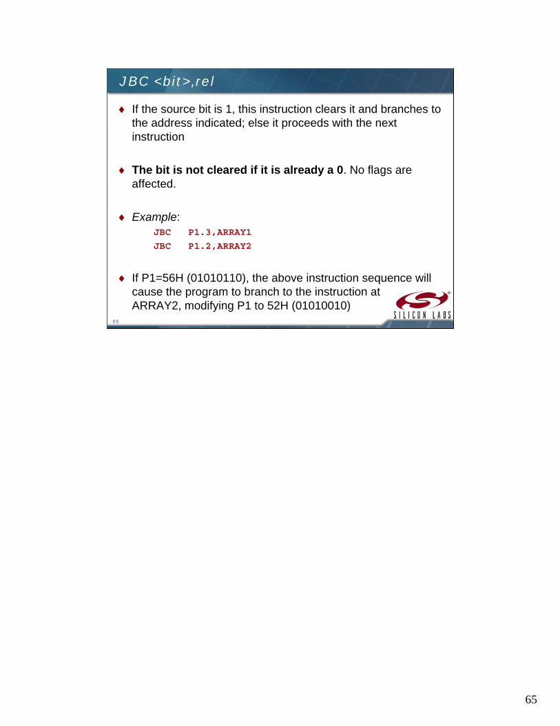
JBC <bit>,rel
If the source bit is 1, this instruction clears it and branches to the address indicated; else it proceeds with the next instruction
The bit is not cleared if it is already a 0. No flags are affected.
Example:JBC P1.3,ARRAY1
JBC P1.2,ARRAY2
If P1=56H (01010110), the above instruction sequence will cause the program to branch to the instruction at ARRAY2, modifying P1 to 52H (01010010)
66
66
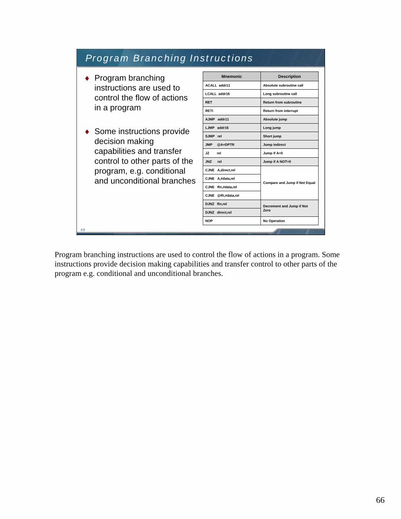
Program Branching Instructions
Program branching instructions are used to control the flow of actions in a program
Some instructions provide decision making capabilities and transfer control to other parts of the program, e.g. conditional and unconditional branches
No OperationNOP
DJNZ direct,rel
Decrement and Jump if Not Zero
DJNZ Rn,rel
CJNE @Ri,#data,rel
CJNE Rn,#data,rel
CJNE A,#data,relCompare and Jump if Not Equal
CJNE A,direct,rel
Jump if A NOT=0JNZ rel
Jump if A=0JZ rel
Jump indirectJMP @A+DPTR
Short jumpSJMP rel
Long jumpLJMP addr16
Absolute jumpAJMP addr11
Return from interruptRETI
Return from subroutineRET
Long subroutine callLCALL addr16
Absolute subroutine callACALL addr11
DescriptionMnemonic
Program branching instructions are used to control the flow of actions in a program. Some instructions provide decision making capabilities and transfer control to other parts of the program e.g. conditional and unconditional branches.

67
67
ACALL addr11
This instruction unconditionally calls a subroutine indicated by the address
The operation will cause the PC to increase by 2, then it pushes the 16-bit PC value onto the stack (low order byte first) and increments the stack pointer twice
The PC is now loaded with the value addr11 and the program execution continues from this new location
The subroutine called must therefore start within the same 2 kB block of the program memory
No flags are affected
Example:ACALL LOC_SUB
If SP=07H initially and the label “LOC_SUB” is at program memory location 0567H, then executing the instruction at location 0230H, SP=09H, internal RAM locations 08H and 09H will contain 32H and 02H respectively and PC=0567H
68
68
LCALL addr16
This instruction calls a subroutine located at the indicated address
The operation will cause the PC to increase by 3, then it pushes the 16-bit PC value onto the stack (low order byte first) and increments the stack pointer twice
The PC is then loaded with the value addr16 and the program execution continues from this new location
Since it is a Long call, the subroutine may therefore begin anywhere in the full 64 kB program memory address space
No flags are affected
Example:LCALL LOC_SUB
Initially, SP=07H and the label “LOC_SUB” is at program memory location 2034H. Executing the instruction at location 0230H, SP=09H, internal RAM locations 08H and 09H contain 33H and 02H respectively and PC=2034H

69
69
RET
This instruction returns the program from a subroutine
RET pops the high byte and low byte address of PC from the stack and decrements the SP by 2
The execution of the instruction will result in the program to resume from the location just after the “call” instruction
No flags are affected
Suppose SP=0BH originally and internal RAM locations 0AH and 0BH contain the values 30H and 02H respectively. The instruction leaves SP=09H and program execution will continue at location 0230H.

70
70
RETI
This instruction returns the program from an interrupt subroutine
RETI pops the high byte and low byte address of PC from the stack and restores the interrupt logic to accept additional interrupts
SP decrements by 2 and no other registers are affected. However the PSW is not automatically restored to its pre-interrupt status
After the RETI, program execution will resume immediately after the point at which the interrupt is detected
Suppose SP=0BH originally and an interrupt is detected during the instruction ending at location 0213H Internal RAM locations 0AH and 0BH contain the values 14H and
02H respectively
The RETI instruction leaves SP=0BH and returns program execution to location 0214H

71
71
AJMP addr11
The AJMP instruction transfers program execution to the destination address which is located at the absolute short range distance (short range means 11-bit address)
The destination must therefore be within the same 2 kBblock of program memory
Example:AJMP NEAR
If the label NEAR is at program memory location 0120H, the AJMP instruction at location 0234H loads the PC with 0120H

72
72
LJMP addr16
The LJMP instruction transfers program execution to the destination address which is located at the absolute long range distance (long range means 16-bit address)
The destination may therefore be anywhere in the full 64 kBprogram memory address space
No flags are affected
Example:LJMP FAR_ADR
If the label FAR_ADR is at program memory location 3456H, the LJMP instruction at location 0120H loads the PC with 3456H

73
73
SJMP rel
This is a short jump instruction, which increments the PC by 2 and then adds the relative value ‘rel’ (signed 8-bit) to the PC
This will be the new address where the program would branch to unconditionally
Therefore, the range of destination allowed is from -128 to +127 bytes from the instruction
Example:SJMP RELSRT
If the label RELSRT is at program memory location 0120H and the SJMP instruction is located at address 0100H, after executing the instruction, PC=0120H.

74
74
JMP @A + DPTR
This instruction adds the 8-bit unsigned value of the ACC to the 16-bit data pointer and the resulting sum is returned to the PC
Neither ACC nor DPTR is altered
No flags are affected
Example:
MOV DPTR, #LOOK_TBL
JMP @A + DPTR
LOOK_TBL: AJMP LOC0
AJMP LOC1
AJMP LOC2
If the ACC=02H, execution jumps to LOC1
AJMP is a two byte instruction
75
75
JZ rel
This instruction branches to the destination address if ACC=0; else the program continues to the next instruction
The ACC is not modified and no flags are affected
Example:SUBB A,#20HJZ LABEL1DEC A
If ACC originally holds 20H and CY=0, then the SUBB instruction changes ACC to 00H and causes the program execution to continue at the instruction identified by LABEL1; otherwise the program continues to the DEC instruction
76
76
JNZ rel
This instruction branches to the destination address if any bit of ACC is a 1; else the program continues to the next instruction
The ACC is not modified and no flags are affected
Example:DEC A
JNZ LABEL2
MOV RO, A
If ACC originally holds 00H, then the instructions change ACC to FFH and cause the program execution to continue at the instruction identified by LABEL2; otherwise the program continues to MOV instruction
77
77
CJNE <dest-byte>,<source-byte>,rel
This instruction compares the magnitude of the dest-byte and the source-byte and branches if their values are not equal
The carry flag is set if the unsigned dest-byte is less than the unsigned integer source-byte; otherwise, the carry flag is cleared
Neither operand is affected
Example:
CJNE R3,#50H,NEQU
… … ;R3 = 50HNEQU: JC LOC1 ;If R3 < 50H
… … ;R3 > 50H
LOC1: … … ;R3 < 50H

78
78
DJNZ <byte>,<rel-addr>
This instruction is ”decrement jump not zero” It decrements the contents of the destination location and if the resulting
value is not 0, branches to the address indicated by the source operand An original value of 00H underflows to FFH No flags are affected
Example:DJNZ 20H,LOC1DJNZ 30H,LOC2DJNZ 40H,LOC3
If internal RAM locations 20H, 30H and 40H contain the values 01H, 5FH and 16H respectively, the above instruction sequence will cause a jump to the instruction at LOC2, with the values 00H, 5EH, and 15H in the 3 RAM locations Note, the first instruction will not branch to LOC1 because the [20H] = 00H,
hence the program continues to the second instruction Only after the execution of the second instruction (where the
location [30H] = 5FH), then the branching takes place
79
79
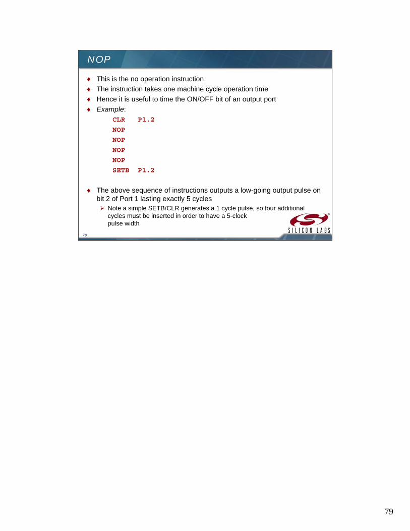
NOP
This is the no operation instruction
The instruction takes one machine cycle operation time
Hence it is useful to time the ON/OFF bit of an output port
Example:
CLR P1.2
NOP
NOP
NOP
NOP
SETB P1.2
The above sequence of instructions outputs a low-going output pulse on bit 2 of Port 1 lasting exactly 5 cycles Note a simple SETB/CLR generates a 1 cycle pulse, so four additional
cycles must be inserted in order to have a 5-clock pulse width

80
80
Learn More at the Education Resource Center
Visit the Silicon Labs website to get more information on Silicon Labs products, technologies and tools
The Education Resource Center training modules are designed to get designers up and running quickly on the peripherals and tools needed to get the design done http://www.silabs.com/ERC
http://www.silabs.com/mcu
To provide feedback on this or any other training go to:
http://www.silabs.com/ERC and click the link for feedback
Visit the Silicon Labs Education Resource Center to learn more about the MCU products.

81
www.silabs.com/MCU