8.13 spa detailed design document register refer to ... · cctv closed-circuit television ce...
TRANSCRIPT
Home of Compassion Crèche Relocation/Heritage Management Plan
Revision: B
studiopacificarchitecture 1902.25 HMP.docx Page 73
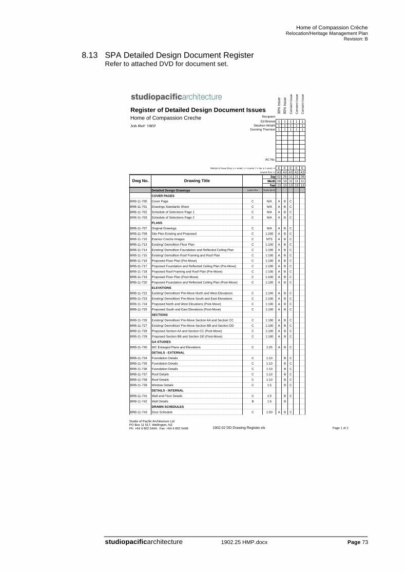
8.13 SPA Detailed Design Document Register Refer to attached DVD for document set.
Studio of Pacific Architecture LtdPO Box 11 517, Wellington, NZPh: +64 4 802 5444; Fax: +64 4 802 5446 1902.02 DD Drawing Register.xls Page 1 of 2
Register of Detailed Design Document IssuesRecipient
Ed Breese 1 1 1 1 1Stephen Wright 1 1 1 1 1
Dunning Thornton 1 1 1 1 1
AC No.
Method of Issue (Key: e = email; c = courier; f = fax; p = post) >> E E E E EIssued Size >> A3 A3 A3 A3 A3
Day 02 25 11 21 26Month 09 10 11 11 11
Year 13 13 13 13 13Detailed Design Drawings Latest Rev Scale @ A3
COVER PAGESBRB-11-700 Cover Page C N/A A B C
BRB-11-701 Drawings Standards Sheet C N/A A B C
BRB-11-702 Schedule of Selections Page 1 C N/A A B C
BRB-11-703 Schedule of Selections Page 2 C N/A A B C
PLANSBRB-11-707 Original Drawings C N/A A B C
BRB-11-709 Site Plan Existing and Proposed C 1:200 A B C
BRB-11-710 Exterior Creche Images C NTS A B C
BRB-11-713 Existing/ Demolition Floor Plan C 1:100 A B C
BRB-11-714 Existing/ Demolition Foundation and Reflected Ceiling Plan C 1:100 A B C
BRB-11-715 Existing/ Demolition Roof Framing and Roof Plan C 1:100 A B C
BRB-11-716 Proposed Floor Plan (Pre-Move) C 1:100 A B C
BRB-11-717 Proposed Foundation and Reflected Ceiling Plan (Pre-Move) C 1:100 A B C
BRB-11-718 Proposed Roof Framing and Roof Plan (Pre-Move) C 1:100 A B C
BRB-11-719 Proposed Floor Plan (Post-Move) C 1:100 A B C
BRB-11-720 Proposed Foundation and Reflected Ceiling Plan (Post-Move) C 1:100 A B C
ELEVATIONSBRB-11-722 Existing/ Demolition/ Pre-Move North and West Elevations C 1:100 A B C
BRB-11-723 Existing/ Demolition/ Pre-Move South and East Elevations C 1:100 A B C
BRB-11-724 Proposed North and West Elevations (Post-Move) C 1:100 A B C
BRB-11-725 Proposed South and East Elevations (Post-Move) C 1:100 A B C
SECTIONSBRB-11-726 Existing/ Demolition/ Pre-Move Section AA and Section CC C 1:100 A B C
BRB-11-727 Existing/ Demolition/ Pre-Move Section BB and Section DD C 1:100 A B C
BRB-11-728 Proposed Section AA and Section CC (Post-Move) C 1:100 A B C
BRB-11-729 Proposed Section BB and Section DD (Post-Move) C 1:100 A B C
GA STUDIESBRB-11-730 WC Enlarged Plans and Elevations C 1:25 A B C
DETAILS - EXTERNALBRB-11-734 Foundation Details C 1:10 B C
BRB-11-735 Foundation Details C 1:10 B C
BRB-11-736 Foundation Details C 1:10 B C
BRB-11-737 Roof Details C 1:10 B C
BRB-11-738 Roof Details C 1:10 B C
BRB-11-739 Window Details C 1:5 B C
DETAILS - INTERNALBRB-11-741 Wall and Floor Details C 1:5 B C
BRB-11-742 Wall Details B 1:5 B
DRAWN SCHEDULESBRB-11-743 Door Schedule C 1:50 A B C
Dwg No.
Home of Compassion CrecheJob Ref: 1902
Drawing Title
Con
sent
Issu
e
Con
sent
Issu
e
Con
sent
Issu
e
90%
Issu
e30
% Is
sue

Home of Compassion Crèche Relocation/Heritage Management Plan
Revision: B
studiopacificarchitecture 1902.25 HMP.docx Page 74
Studio of Pacific Architecture LtdPO Box 11 517, Wellington, NZPh: +64 4 802 5444; Fax: +64 4 802 5446 1902.02 DD Drawing Register.xls Page 2 of 2
Day 02 25 11 21 26Month 09 10 11 11 11
Year 13 13 13 13 13Detailed Design Drawings Latest Rev Scale @ A3
Dwg No. Drawing Title
BRB-11-746 Window Schedule C 1:50 A B C
BRB-11-747 Window Schedule C 1:50 A B C
BRB-11-748 Window Schedule C 1:50 A B C
1902.23 WRITTEN SCOPES AND SCHEDULES1902.23 Indicative Scope of Work: Initial and Demolition B B
1902.23 Indicative Scope of Work: Refurbishment D D
1902.23 Schedule of Work to Original Fabric B B
1902.23 Site Specific Induction Sheet A
1902.23 SPECIFICATION1220 Project A A1222 Project Personel A A1222L Project Personel - LBPs A A1231 Contract A A1232 Interpretation & Definitions A A1233 Referenced Documents A A1234 Documentation A A1235 Shop Drawings A A1237 Warranties A A1237WA Warranty Agreement A A1240 Establishment A A1250 Temporary Works & Services A A1256 Waste Management A A1269 Project Management A A1270 Construction A A1280 Heritage Requirements A1282 Protection/Removal of Heritage Fabric A2112 Partial Demolition A A2123 Asbestos Removal A A3124 Finishes to Wey Concrete A A3821 Timber Framing A A4161T Thermakraft Underlays, Foils & DPC A A4221 Timber Board Cladding A A4224 Timber Exterior Trim A A4231V PBS Ventclad Plastered Finish Cladding A A4238CB Celecrete Block A A4272 Brick Slip Veneer A A4282 Solid Plaster A A4311 Profiled Metal Roofing A A4311C Calder Stewart Eurotray A A4337E Ecoply Roofing A A4421 Bitumen Based Sheet Roofing A A4422D De Boer Duo A A4511 New Exterior Timber Windows & Doors A A4512 Repairs to Existing Timber Windows A A4611 Glazing Exterior A A4711A Autex Greenstuff Thermal Insulation A A4811S Sika Sealants A A4821 Flashings A A4911 Cast Iron Metalwork A A5432 Timber Strip Floors A A5521 Hardware A A6700R Resene Painting General A A6711R Resene Painting Exterior A A6721R Resene Painting Interior A A6745R Resene Protective Coatings - Steelwork A A7151 Sanitary Fixtures, Tapware & Accessories A A7411C Continuous Spouting Rainwater Systems A A


General Notes: All dimensions to be checked on site.Copyright in all drawings, specifications and other documentsand in the work executed from them remains the property ofS t u d i o o f P a c i f i c A r c h i t e c t u r e L t d .© Studio of Pacific Architecture Limited 2012
A3Orig. Size:Scale:
Revisions: Project Title:
BRB-11-700
Cover Sheet
at18 Buckle Street, WellingtonforMemorial Park Alliance
Consultants:
A r c h i t e c t sU r b a n D e s i g n e r sI n t e r i o r D e s i g n e r s
www.studiopacific.co.nzemail: [email protected]
TEL: 64 4 802 5444FAX: 64 4 802 5446
Home of Compassion Creche
L e v e l 27 4 C u b a S tP . O . B o x 1 1 - 5 1 7W e l l i n g t o n , N Z Revision:
1902Job No.:Drawing No.
FOR CONSENT
DUNNING THORNTON CONSULTANTS
LEVEL 9, 94 DIXON STREET
WELLINGTON 6030
CA 30% ISSUE DATE: 2013-09-02B 90% ISSUE DATE: 2013-10-25C FOR CONSENT DATE: 2013-11-11
Studio of Pacific Architecture LtdPO Box 11 517, Wellington, NZPh: +64 4 802 5444; Fax: +64 4 802 5446 1902.02 DD Drawing Register.xls Page 1 of 1
Detailed Design DrawingsCOVER PAGES
BRB-11-700 Cover Page
BRB-11-701 Drawings Standards Sheet
BRB-11-702 Schedule of Selections Page 1
BRB-11-703 Schedule of Selections Page 2
PLANSBRB-11-707 Original Drawings
BRB-11-709 Site Plan Existing and Proposed
BRB-11-710 Exterior Creche Images
BRB-11-713 Existing/ Demolition Floor Plan
BRB-11-714 Existing/ Demolition Foundation and Reflected Ceiling Plan
BRB-11-715 Existing/ Demolition Roof Framing and Roof Plan
BRB-11-716 Proposed Floor Plan (Pre-Move)
BRB-11-717 Proposed Foundation and Reflected Ceiling Plan (Pre-Move)
BRB-11-718 Proposed Roof Framing and Roof Plan (Pre-Move)
BRB-11-719 Proposed Floor Plan (Post-Move)
BRB-11-720 Proposed Foundation and Reflected Ceiling Plan (Post-Move)
ELEVATIONSBRB-11-722 Existing/ Demolition/ Pre-Move North and West Elevations
BRB-11-723 Existing/ Demolition/ Pre-Move South and East Elevations
BRB-11-724 Proposed North and West Elevations (Post-Move)
BRB-11-725 Proposed South and East Elevations (Post-Move)
SECTIONSBRB-11-726 Existing/ Demolition/ Pre-Move Section AA and Section CC
BRB-11-727 Existing/ Demolition/ Pre-Move Section BB and Section DD
BRB-11-728 Proposed Section AA and Section CC (Post-Move)
BRB-11-729 Proposed Section BB and Section DD (Post-Move)
GA STUDIESBRB-11-730 WC Enlarged Plans and Elevations
DETAILS - EXTERNALBRB-11-734 Foundation Details
BRB-11-735 Foundation Details
BRB-11-736 Foundation Details
BRB-11-737 Roof Details
BRB-11-738 Roof Details
BRB-11-739 Window Details
DETAILS - INTERNALBRB-11-741 Wall and Floor Details
DRAWN SCHEDULESBRB-11-743 Door Schedule
BRB-11-746 Window ScheduleBRB-11-747 Window ScheduleBRB-11-748 Window Schedule
Dwg No. Drawing Title
DRAWING LIST
Home of Compassion CrecheConsent Issue
11th November 2013

General Notes: All dimensions to be checked on site.Copyright in all drawings, specifications and other documentsand in the work executed from them remains the property ofS t u d i o o f P a c i f i c A r c h i t e c t u r e L t d .© Studio of Pacific Architecture Limited 2012
A3Orig. Size:Scale:
Revisions: Project Title:
BRB-11-701
Drawing Standards
at18 Buckle Street, WellingtonforMemorial Park Alliance
Consultants:
A r c h i t e c t sU r b a n D e s i g n e r sI n t e r i o r D e s i g n e r s
www.studiopacific.co.nzemail: [email protected]
TEL: 64 4 802 5444FAX: 64 4 802 5446
Home of Compassion Creche
L e v e l 27 4 C u b a S tP . O . B o x 1 1 - 5 1 7W e l l i n g t o n , N Z Revision:
1902Job No.:Drawing No.
FOR CONSENT
DUNNING THORNTON CONSULTANTS
LEVEL 9, 94 DIXON STREET
WELLINGTON 6030
CA 30% ISSUE DATE: 2013-09-02B 90% ISSUE DATE: 2013-10-25C FOR CONSENT DATE: 2013-11-11
120-10
120-01
20-10
1
2
3
4
125-01
340-01
1
6 GA PLAN: GROUND FLOORSCALE 1:5020-01
130-01
130-01
140-01
140-01
140-01
140-01
Level 1FL 10.000
RL 10.000
FCL 10.000
FL 0
FL 0
FL 0
Detail number
Reference to sheet that study or detailis drawn. "–" denotes study or detail ison the same page.
Revision number
Area or item revised
Space number = 01
Level number = 1
Space name
Level and Louvre number
Type
L = Louvre
Type
Level and Window number
W = Window
Level and Door number
D = Door
Type
Hexagon denotes plan study.Circle denotes elevation,section, or other type of study
Drawing/detail number
Drawing series/sub-series:GA Plan, RCP, GA Section etc
Back reference to the drawing sheet that thisdrawing is referenced from. "–" denotes thatthe reference is on the same page
Drawing name
Hexagon denotes plan drawing.Circle denotes elevation, section, or othertype of drawing
ABBREVIATIONS
Based on NZS/AS 1100.101–92
ad Above datumadj. Adjustableagg. Aggregateal. Aluminiumalt. Alternateap Access panelappr. Approvedapprox. Approximate(ly)AS Australian Standard
B Bathbdt Bidetbldg Buildingblk Blockbm Bench markBS British Standardbot. c Bottle chiller
CAD Computer-Aided Drawingcb Coach boltCBI Coordinated Building Informationc/c Center to centercctv Closed-circuit televisionce Cleaning eyeCHS Circular hollow sectioncj Construction jointcl. s Cleaners sinkcnr. CornerCode Building Codecol. Columnconc. Concretecorr. Corrugatedcos. Check on sitecp Cesspitcpd Cupboardcrs. Centerscs Coach screwcsk Countersunk
D DeformedDB Distribution Boarddf Drinking fountaindh Double hungDHS Dimond Hi-span (Metal Purlin)dia. Diameterdiag. Diagonaldim Dimensiondp Downpipedpc Damp proof coursedpm Damp proof membranedry Clothes Dryerdw Dishwasherdwg Drawing
ef Each Faceew Each Wayej Expansion Jointeq Equalexist. Existingext Externalextg Existing
f Fixedfa Fire alarmfap Fire alarm panelfbi Fire brigade inletfcl Finished ceiling levelfe Fire extinguisherff Fridge / FreezerFFL Finished floor fevelfg Fixed glassfh Fire hydrantfhr Fire hose reelfip Fire indicator panelfloat Dimension to suitFr. FreezerFRR Fire resistance ratingfw Floor waste
Based on NZS/AS 1100.101–92
s Sinksan. du Sanitary disposal unitsc Sawcut jointsch Schedulesched Schedulescp Satin chrome platesed Small end diametersep. t Septic tanksh. Showershwr. ShowerSHS Square hollow sectionsht SheetSk SketchSL Structural Levelspec Specificationspr. Sprinklersqm Square metresq Squaress Stainless steelSTC Sound transmission classswbd Switchboard
ta To abovetb To belowtba To be advisedtbc To be confirmedtfb Taper flange beamtfc Taper flange channeltgv Tongue, groove and vee Jointtub Laundry tubtv Terminal venttyp Typical
UB Universal beamUC Universal columnur. Urinalu/g Undergroundu/s Underside
Van u. Vanity unitvert. Vertical
W Wattwc Water closet (Toilet Pan)whb Wash hand basinwm Washing machineww Wastewater (soil/sewer) pipe
ABBREVIATIONS
EXTERIOR ELEVATION
PLAN DETAIL
INTERNAL ELEVATIONS 1-4 INTERNAL ELEVATION
REFERENCE TO LARGER SCALE PLAN, SECTIONOR ELEVATION STUDY FROM SMALLER SCALEPLAN, SECTION OR ELEVATION
SECTION
NORTH POINT
GRID REFERENCES
DRAWING REFERENCE SYMBOLS
REFERENCE SYMBOLS
DRAWING REFERENCE TEXT
DRAWING TITLES
REVISION SYMBOLS
EXPRESSION OF LEVELS
Existing spot level
New spot level
Reference level (plan view)
Reference floor levels shown on sections,elevations and details(Primary reference)
All levels will be prefixed as follows:Floor LevelGround LevelReduced LevelStructural Surface Level(for concrete work SL includes all concretetopping slabs and levelling screeds)Finished Floor LevelFinished Ceiling level
Levels are shown in terms of survey datum.
All levels as per AS 1100.301 – 1985
SPACE NUMBERING
DRAWING ANNOTATION
DOORS, WINDOWS AND LOUVRES
Refer to the plan, elevation and section drawings, and theDoor Window and Louvre schedules for more information
WINDOWS
Refer Window schedule for key to window types
LOUVRES
Refer Louvre schedule for key to louvre types
L1.02/13
W1.02/13
D1.02/13
1
A
Setout module line shown for secondaryelements and critical elements.(Secondary reference)
PC module
Finished ceiling levels shown on sections,elevations and details
ROOM1.01
DOORS
Refer Door schedule for key to door types
SECTION DETAIL
FLGLRLSL
FFLFCL
ABBREVIATIONS
Based on NZS/AS 1100.101–92
galv. Galvanisedgi Galvanised irongl GlassGL Ground levelgms Galvanised mild steelgr. t Grease trapgt Gully trap
H Hydranthd bolt Holding down bolthdg Hot dipped galvanisedhoriz. Horizontalht heightHT Hose taphtr Heated towel railhwc Hot water cylinder
ib Inspection bendic Inspection chamberid Internal diameterij Inspection junctionil Invert levelinsul. InsulationISO International Standards Organisation
kg KilogramkW Kilowatt
l Litrelh Left handlhce Lamphole cleaning eye
M ISO Metric boltsmax. Maximummh Manholemisc. Miscellaneousm Metremm Millimetrems Mild steelMSB Main Switch Board
nb Nominal boreno. Numbernom. Nominalnts Not to scaleNZBC New Zealand Building CodeNZS New Zealand Standard
o/a Overallo/f Overflowo/h Overheadod Outside diameteros Overall size
pc Precast concretePFC Parallel flange channelply Plywoodptn Partition
qty Quantity
R Radiusr Roundrad. RadiatorRad. Radiatarc Reinforced concreteref. Referencereinf. Reinforcementreqd. Requiredrh Right handRHS Rectangular hollow sectionRL Reduced Levelro Rough openingROW Right of wayRSA Rolled steel angleRSC Rolled steel channelRSJ Rolled steel joistrw Rainwater piperwh Rainwater headrwo Rainwater outletrws Rainwater sump

General Notes: All dimensions to be checked on site.Copyright in all drawings, specifications and other documentsand in the work executed from them remains the property ofS t u d i o o f P a c i f i c A r c h i t e c t u r e L t d .© Studio of Pacific Architecture Limited 2012
A3Orig. Size:Scale:
Revisions: Project Title:
BRB-11-702
Schedule of Selections 1
at18 Buckle Street, WellingtonforMemorial Park Alliance
Consultants:
A r c h i t e c t sU r b a n D e s i g n e r sI n t e r i o r D e s i g n e r s
www.studiopacific.co.nzemail: [email protected]
TEL: 64 4 802 5444FAX: 64 4 802 5446
Home of Compassion Creche
L e v e l 27 4 C u b a S tP . O . B o x 1 1 - 5 1 7W e l l i n g t o n , N Z Revision:
1902Job No.:Drawing No.
FOR CONSENT
DUNNING THORNTON CONSULTANTS
LEVEL 9, 94 DIXON STREET
WELLINGTON 6030
CA 30% ISSUE DATE: 2013-09-02B 90% ISSUE DATE: 2013-10-25C FOR CONSENT DATE: 2013-11-11
PRODUCT CODE GENERIC NAME PRODUCT DETAILS(BRAND, MODEL, FINISH, COLOUR ETC)
LOCATION SPEC REF
REV.
2 SITEDEMOLITION 2111
21X ELEMENTS FOR SALVAGE THAT REMAIN THE PROPERTY OF NZTA.
Refer to 'Schedule of Items for Removal'
2111 A
21X ELEMENT FOR RE-USE
Refer to 'Schedule of Items for Removal'
2111 A
PRODUCT CODE GENERIC NAME PRODUCT DETAILS(BRAND, MODEL, FINISH, COLOUR ETC)
LOCATION SPEC REF
REV.
3 STRUCTURECODE PRODUCT TYPE PRODUCT SELECTED LOCATION SPEC REV31X CAST IN SITU
CONCRETETo engineers details and specification
3100 A
FINISHES TO WET CONCRETE 31243124A FLOOR Finish: Smooth trowelled U3 Verandah 3124 A
3124B STEPS Finish: F4 suitable for plaster Steps to front entry, and to verandah.
3124
TIMBER FRAMING APRIL 2009 38213821 GEN ALL NEW TIMBER Shall be date stamped.
3821 note PREDRILL Holes into original timber to be predrilled.
3821 note ROOF FRAMING -CEILING JOISTS
Salvage and reuse existing.If additional needed, new is Radiata H1.1, size to matc.
if required 3821 A
3821 note ROOF FRAMING -VALLEY BOARDS
Salvage and reuse existing.If additional needed, new is Radiata H3.1, Merchantable, size to match.
if required 3821 A
3821 note SUB FLOOR FRAMING - GROUND FLOOR JOISTS
refer to Structural Engineer's documents.
A
3821A ROOF FRAMING -TIMBER RAFTERS
Salvage and reuse existing.If additional needed, new is Radiata H1.2, size to match.Grade: MS8
Roof 3821 A
3821B TIMBER EXTERIOR WALL FRAMING
Species: Radiata PineGrade: SG8Treatment: H1.2
New framing around chimney
3821 A
3821C EXISTING TIMBER EXTERIOR WALL FRAMING
Reinstate existing stored posts, lintels, beams, balustrade, or new timber to match species and profile.
Verandah 3821 A
3821D TIMBER INTERNAL GUTTER FRAMING
Species: Radiata PineGrade: SG8Treatment: H3.2
New gutter 3821 A
3821F INTERIOR STRUCTURAL AND BRACED TIMBER WALL FRAMING
Species: Radiata PineGrade: MSG8Treatment: H1.2
New framing around chimney
3821 A
3821G ROOF FRAMING -SARKING
Salvage and reuse existing.If additional needed, source new Radiata H3.1 to match.
As required to access roof.
3821 A
PRODUCT CODE GENERIC NAME PRODUCT DETAILS(BRAND, MODEL, FINISH, COLOUR ETC)
LOCATION SPEC REF
REV.
4 ENCLOSURECODE PRODUCT TYPE PRODUCT SELECTED LOCATION SPEC REV
WRAPS, UNDERLAY AND DPC 41614161A ss B4161B DPC Type: Thermakraft Supercourse 500 to separate
timber/steel from concrete
4161T B
4161C ss B4161D ROOFING
UNDERLAYType: Thermakraft Covertech 407 Under corrugate
roofing4161T B
4161E PEF ROD Type: Thermakraft Window WormSize: to suit
new windows 4161T B
TIMBER BOARD CLADDING 42214221 GEN ALL TIMBER Principle is to retain existing timber
where ever possible. All new timber to be date stamped.
B
4221A TIMBER BOARDS Retain existing timber, repair as necessary, refurbish, Paint finish
Existing soffits, and verandah roof, north gablet
4221 B
4221B TIMBER BOARDS Species/grade: RadiataTreatment: H3.2Finish: PaintProfile: Match existing T&G boards
New soffit over north soffit bay window,If required, soffit of gablet
4221 B
4221C TIMBER BOARDS Species/grade: RadiataTreatment: H3.2Finish: PaintProfile: Match existing on south
North gable end 4221 B
4221D TIMBER BOARDS RAG TAIL
Reinstate timber panels Repair as necessaryRefurbishPaint Finish if new needed, radiata H3.2, paint profile to match.
Verandah - high level rag tail vertical board cladding
4221 B
TIMBER EXTERIOR TRIM 42244224A TIMBER EXTERIOR
TRIMSpecies/grade: RadiataTreatment: H3.2Finish: PaintSize to match existing.
fascias, barge boards
4224 B
FIBRE CEMENT SHEET CLADDING - ETERPAN 42314231A FLUSH STOPPED
9MM CLADDING SHEETS
Manufacturer/brand:Eterpan BaseSize: 9mm x 1200mm x 2400mm VentClad SystemVeneer: 20mm Brick Slip and plaster
Chimney, gablet soffit.
4231E B
4231B CAVITY BATTENS Timber species: Radiata PineTimber grade:merchant gradeTreatment: H3.1
Chimney 4231E B
4231C ss 4231E B4231D RIGID AIR BARRIER Brand: Ecoply
Thickness: 12mm Treatment: H3.2
Chimney 4231E B
AERATED CONCRETE 42384238A AAC Hebel shaped to match existing
original profiles. From 100mm Power Panel.
Chimney 4238 B
BRICK 4272 B4272A BRICK SLIP
CLADDINGCarefully remove and store existing bricks off chimney.Bricks to be cut down into 20mm brick slipsAdhesive fixed to substrateJoints - Mortar pointed
Chimney - external
4272 B
4272B BRICK POINTING EXISTING BRICK WORK
Rake out all pointing to min. 25mm depth and repoint with lime putty mix per original coloured to match existing.
All exterior walls na B
SOLID PLASTER 42824282A SOLID PLASTER -
EXTERIORBackground: existing solid plasterFinish: to match existingColour: to match existingRefer to specification section for details
Repairs, and recoat of existing, window surrounds, parapet, skirt, entry steps, verandah steps
4282 B
4282B SOLID PLASTER - EXTERIOR
Background: Rigid fiber cement sheet with building paper over, no building paper over AAC forms.Finish: to match existingColour: to match existingRefer to specification section for details
New work; Chimney
4282 B
4282C FLAT METAL LATH Brand: HelifixMaterial: Grade 316 stainless steel
External walls chimney
4282 B
PRODUCT CODE GENERIC NAME PRODUCT DETAILS(BRAND, MODEL, FINISH, COLOUR ETC)
LOCATION SPEC REF
REV.
4282D SLIP LAYER Brand: ThermakraftMaterial: 210 Building paper
External walls chimney
4282 B
PROFILED METAL ROOFING 43114311 NOTE FLASHINGS -
GENERALLYMaterial: to match roofThickness: 0.55mm
4311 A
4311A s/s B4311B ALUMINIUM/ZINC
COATED STEEL, UNPAINTED
Brand: ZincalumeProfile: Corrugated BMT: 0.40mmG300 Steel
Main roof 4311 A
4311C ALUMINIUM/ZINC COATED STEEL, UNPAINTED
Calder Stewart 'Eurotray', with rollcap to match original profileBrand: Zincalume BMT: 0.40mmG300 Steel
Bay Window roof
4311C B
4311 note SPOUTING, DOWNPIPES
Refer to 7411 B
PLYWOOD ROOFING 43374337A PLYWOOD ROOF
UNDERLAYGrade: C-D with C face upwards Thickness: 18 mm Treatment: H3.2 CCA. DO NOT USE LOSP Treated timber. NOTE - refer to the 4337 specification for ply roof requirements prior to fixing. Ply roofing with membrane over to be sighted and approved by installer.
Internal gutter 4337 B
4337B SCREWS Type/size/material: Fixing: - note minimum fixing requirement for membrane - Screw fixing using countersunk stainless steel screws, gauge 10 and a length three times the thickness of the plywood in accordance with E2/AS1.
internal gutter 4337 B
SHEET MEMBRANE ROOFING 44224422A MEMBRANE
ROOFINGDe Boer Duo SlatesTwo layer torch on modified bitumen.
Internal Gutter 4422 B
EXTERIOR TIMBER WINDOWS AND DOORS 451145 NOTE WIND ZONE -
DESIGN TO NZS 3604
Building wind zone: 3 (high) (as determined by engineer.
4511 B
4511A EXTERIOR TIMBER WINDOWS - EXISTING
Windows and frames to be retained in place. Repair as requiredReglaze as noted on drawings.Prepare and repaint refer Painting SpecNew cords to sashesNew hardware
all remainder 4511 B
4511B EXTERIOR TIMBER WINDOWS - NEW
Timber - Heart Mataimaterials, dimensions and detailing to match originalPaint refer Painting SpecNew hardware per Window and Door Schedule.
W1.07 to W1.10 4511 B
4511C s/s s/s s/s 4511 B4511D s/s s/s s/s 4511 B4511E s/s s/s s/s 4511 B4511F STANDARD DOORS Refer to Schedule of Items for
Removal.Repair as requiredReglaze as per Window and Door SchedulePrepare and repaint refer Painting SpecNew hardware per Window and Door Schedule.
Front door and back door
4511 C
GLAZING EXTERIOR 461146 NOTE WIND ZONE Building wind zone: 3 (high) (as
determined by engineer.4611 A
4611A CLEAR FLOAT GLASS - EXISTING
Weight for size. Replacing broken or coloured/wired glass in existing windows per drawings.
4611 C
4611B CLEAR FLOAT GLASS - NEW
6mm New windows B
General Notes: All dimensions to be checked on site.Copyright in all drawings, specifications and other documentsand in the work executed from them remains the property ofS t u d i o o f P a c i f i c A r c h i t e c t u r e L t d .© Studio of Pacific Architecture Limited 2012
A3Orig. Size:Scale:
Revisions: Project Title:
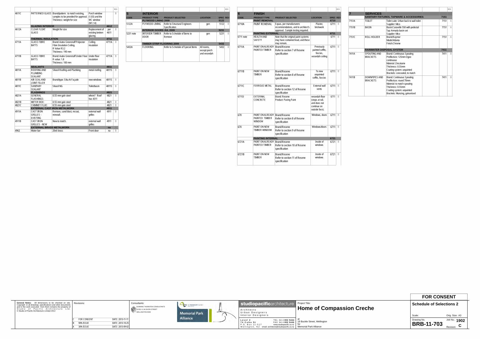
BRB-11-703
Schedule of Selections 2
at18 Buckle Street, WellingtonforMemorial Park Alliance
Consultants:
A r c h i t e c t sU r b a n D e s i g n e r sI n t e r i o r D e s i g n e r s
www.studiopacific.co.nzemail: [email protected]
TEL: 64 4 802 5444FAX: 64 4 802 5446
Home of Compassion Creche
L e v e l 27 4 C u b a S tP . O . B o x 1 1 - 5 1 7W e l l i n g t o n , N Z Revision:
1902Job No.:Drawing No.
FOR CONSENT
DUNNING THORNTON CONSULTANTS
LEVEL 9, 94 DIXON STREET
WELLINGTON 6030
CA 30% ISSUE DATE: 2013-09-02B 90% ISSUE DATE: 2013-10-25C FOR CONSENT DATE: 2013-11-11
PRODUCT CODE GENERIC NAME PRODUCT DETAILS(BRAND, MODEL, FINISH, COLOUR ETC)
LOCATION SPEC REF
REV.
4611C PATTERNED GLASS Brand/pattern: to match existing, samples to be provided for approval.Thickness: weight for size
Porch window (1.03) and the WC window (W1.14)
B
GLAZING INTERIOR 46124612A CLEAR FLOAT
GLASSWeight for size Replacement of
existing broken glazing
per 4611
B
THERMAL INSULATION 47114711A GLASS FIBRE
BATTSBrand: Autex Greenstuff Polyester Fibre Insulation Ceiling.R Value R3.2Thickness: 190 mm
Ceiling insulation
4711A B
4711B GLASS FIBRE BATTS
Brand: Autex Greenstuff Under FloorR value: 1.8Thickness: 100 mm
Under floor insulation
4711A B
SEALANTS 48114811A ROOFING AND
PLUMBING SEALANT
Sikasil Roofing and Plumbing metal roofing 4811S B
4811B AIR SEAL AND JOINT FILLER
Brand/type: Sika At Façade new windows 4811S B
4811C SANITARY SEALANT
Sikasil NG Toilet/basin 4811S B
FLASHINGS 48214821A GENERAL
FLASHINGS: 0.55 mm galv steel where? Roof
has 43114821 B
4821B METER BOX: 0.55 mm galv steel 4821 B4821C CHIMNEY FLUE: 0.55 mm galv steel 4821 B
EXTERNAL CAST IRON METALWORK 49114911A CAST IRON
GRILLES - EXISTING
Remove, sand blast, recoat, reinstall.
external wall grilles
4911 B
4911B CAST IRON GRILLES - NEW
New to match. external wall grilles
4911 B
EXTERNAL BRASS METALWORK na B4962 Water bar 20x6 brass Front door na B
PRODUCT CODE GENERIC NAME PRODUCT DETAILS(BRAND, MODEL, FINISH, COLOUR ETC)
LOCATION SPEC REF
REV.
5 INTERIORCODE PRODUCT TYPE PRODUCT SELECTED LOCATION SPEC REV
PLYWOOD LINING 2009 51225122A PLYWOOD LINING Refer to Structural Engineers
Specificationgen 5122 B
52315231 note INTERIOR TIMBER
DOOR Refer to Schedule of Items to Remove
gen 5231 B
54325432A FLOORING Refer to Schedule of Special Items All rooms,
except porch and verandah
5432 B
INTERIOR DOORS JUL 2009
TIMBER STRIP FLOORING 2009
PRODUCT CODE GENERIC NAME PRODUCT DETAILS(BRAND, MODEL, FINISH, COLOUR ETC)
LOCATION SPEC REF
REV.
6 FINISHCODE PRODUCT TYPE PRODUCT SELECTED LOCATION SPEC REV
PAINT REMOVAL 67106710A PAINT REMOVAL Equus, per manufacturers
recommendations, and to architect's approval. Sample testing requried.
Plaster, brickwork
6711 B
PAINTING EXTERNAL 67116711 note HEALTH AND
SAFETYNote that the original paint systems may have contained lead, and these may remain.
6711 B
6711A PAINT ON ALREADY PAINTED TIMBER
Brand:ReseneRefer to section 7 of Resene specification
Previously painted soffits,
fascias, verandah ceiling
6711 B
6711B PAINT ON NEW TIMBER
Brand:ReseneRefer to section 8 of Resene specification
To new unpainted
soffits, fascias
6711 B
6711C FERROUS METAL Brand:ReseneRefer to section 12 of Resene specification
External wall vents
6711 B
6711D EXTERNAL CONCRETE
Brand: ReseneProduct: Paving Paint
verandah floor (stops at rail, and does not continue on outside face).
6711 B
67X PAINT ON ALREADY PAINTED TIMBER WINDOW
Brand:ReseneRefer to section 8 of Resene specification
Windows, doors 6711 B
67X PAINT ON NEW TIMBER WINDOW
Brand:ReseneRefer to section 9 of Resene specification
Windows/doors 6711 B
PAINTING INTERNAL 67216721A PAINT ON ALREADY
PAINTED TIMBERBrand:ReseneRefer to section 10 of Resene specification
Inside of windows
6721 B
6721B PAINT ON NEW TIMBER
Brand:ReseneRefer to section 11 of Resene specification
Inside of windows
6721 B
PRODUCT CODE GENERIC NAME PRODUCT DETAILS(BRAND, MODEL, FINISH, COLOUR ETC)
LOCATION SPEC REF
REV.
7 SERVICESSANITARY FIXTURES, TAPWARE & ACCESSORIES 7151
7151A TOILET Toilet suite: Urban back to wall toiletSupplier: Mico
7151 A
7151B BASIN Basin:Caravelle 550 with pedestalTap: Armada basin setSupplier: Mico
7151 A
7151C ROLL HOLDER Brand:RaymorModel:AtlantaFinish:Chrome
7151 A
RAINWATER DISPOSAL SYSTEM 74117411A SPOUTING AND
BRACKETSBrand: Continuous SpoutingProfile/size: 125mm Ogee continuousMaterial: ZincalumeThickness: 0.55mmCoating system: unpaintedBrackets: concealed, to match
7411 B
7411B DOWNPIPES AND BRACKETS
Brand: Continuous SpoutingProfile/size: round 70mmMaterial: to match spoutingThickness: 0.55mmCoating system: unpaintedBrackets: Munzing, galvanised
7411 B

General Notes: All dimensions to be checked on site.Copyright in all drawings, specifications and other documentsand in the work executed from them remains the property ofS t u d i o o f P a c i f i c A r c h i t e c t u r e L t d .© Studio of Pacific Architecture Limited 2012
A3Orig. Size:Scale:
Revisions: Project Title:
BRB-11-707
Original Drawings
at18 Buckle Street, WellingtonforMemorial Park Alliance
Consultants:
A r c h i t e c t sU r b a n D e s i g n e r sI n t e r i o r D e s i g n e r s
www.studiopacific.co.nzemail: [email protected]
TEL: 64 4 802 5444FAX: 64 4 802 5446
Home of Compassion Creche
L e v e l 27 4 C u b a S tP . O . B o x 1 1 - 5 1 7W e l l i n g t o n , N Z Revision:
1902Job No.:Drawing No.
FOR CONSENT
DUNNING THORNTON CONSULTANTS
LEVEL 9, 94 DIXON STREET
WELLINGTON 6030
CA 30% ISSUE DATE: 2013-09-02B 90% ISSUE DATE: 2013-10-25C FOR CONSENT DATE: 2013-11-11
02 Original Drawings
1:1.1792
General Notes: All dimensions to be checked on site.Copyright in all drawings, specifications and other documentsand in the work executed from them remains the property ofS t u d i o o f P a c i f i c A r c h i t e c t u r e L t d .© Studio of Pacific Architecture Limited 2012
A3Orig. Size:Scale:
Revisions: Project Title:
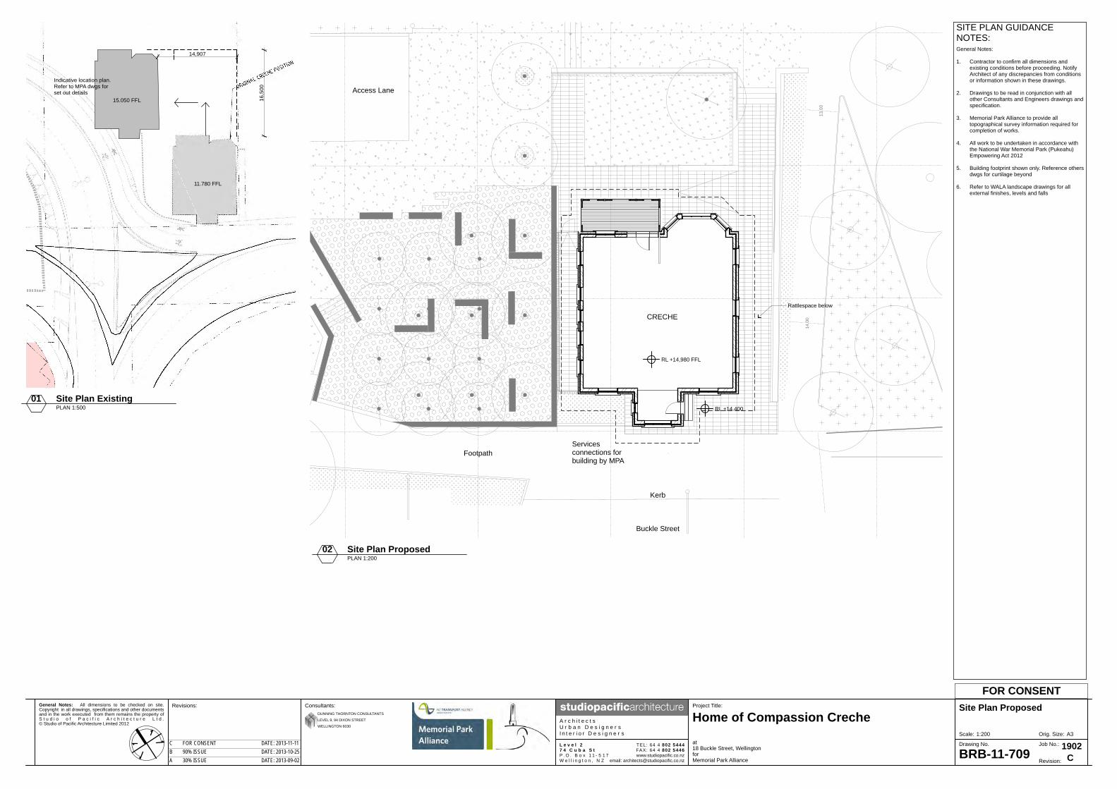
BRB-11-709
Site Plan Proposed
at18 Buckle Street, WellingtonforMemorial Park Alliance
Consultants:
A r c h i t e c t sU r b a n D e s i g n e r sI n t e r i o r D e s i g n e r s
www.studiopacific.co.nzemail: [email protected]
TEL: 64 4 802 5444FAX: 64 4 802 5446
Home of Compassion Creche
L e v e l 27 4 C u b a S tP . O . B o x 1 1 - 5 1 7W e l l i n g t o n , N Z Revision:
1902Job No.:Drawing No.
FOR CONSENT
DUNNING THORNTON CONSULTANTS
LEVEL 9, 94 DIXON STREET
WELLINGTON 6030
CA 30% ISSUE DATE: 2013-09-02B 90% ISSUE DATE: 2013-10-25C FOR CONSENT DATE: 2013-11-11
SITE PLAN GUIDANCENOTES:General Notes:
1. Contractor to confirm all dimensions andexisting conditions before proceeding. NotifyArchitect of any discrepancies from conditionsor information shown in these drawings.
2. Drawings to be read in conjunction with allother Consultants and Engineers drawings andspecification.
3. Memorial Park Alliance to provide alltopographical survey information required for
completion of works.
4. All work to be undertaken in accordance withthe National War Memorial Park (Pukeahu)Empowering Act 2012
5. Building footprint shown only. Reference othersdwgs for curtilage beyond
6. Refer to WALA landscape drawings for allexternal finishes, levels and falls
14,907
16,5
00
Indicative location plan.Refer to MPA dwgs forset out details
11.780 FFL
15.050 FFL
RL +14,980 FFL
RL +14.400
Rattlespace below
Access Lane
Footpath
Kerb
Buckle Street
CRECHE
Servicesconnections forbuilding by MPA
14.0
0
13.0
0
02 Site Plan ProposedPLAN 1:200
01 Site Plan ExistingPLAN 1:500
1:200

General Notes: All dimensions to be checked on site.Copyright in all drawings, specifications and other documentsand in the work executed from them remains the property ofS t u d i o o f P a c i f i c A r c h i t e c t u r e L t d .© Studio of Pacific Architecture Limited 2012
A3Orig. Size:Scale:
Revisions: Project Title:
BRB-11-710
Creche Exterior Images
at18 Buckle Street, WellingtonforMemorial Park Alliance
Consultants:
A r c h i t e c t sU r b a n D e s i g n e r sI n t e r i o r D e s i g n e r s
www.studiopacific.co.nzemail: [email protected]
TEL: 64 4 802 5444FAX: 64 4 802 5446
Home of Compassion Creche
L e v e l 27 4 C u b a S tP . O . B o x 1 1 - 5 1 7W e l l i n g t o n , N Z Revision:
1902Job No.:Drawing No.
FOR CONSENT
DUNNING THORNTON CONSULTANTS
LEVEL 9, 94 DIXON STREET
WELLINGTON 6030
CA 30% ISSUE DATE: 2013-09-02B 90% ISSUE DATE: 2013-10-25C FOR CONSENT DATE: 2013-11-11
Bay window roof corrugatediron (replaced earlier tray
roof)
Shingles or ventilatinglouvre as specification
Original door glazed, maybe stabletype with solid bottom panel
Concrete foundation wallto timber floor as specifiedor concrete floor slab?
Non-original paint finish to palster
Non-original paint finishto original brickwork
Original infill panel to balustrade
Non original windows x3 in bay
Non-original door
Non-original windows
Possible original windows (addition)
Non-original lean-to
Non-original cladding infill
Non-original guttering
Canopy to door Non-original satellite dish
Original flat iron panel infill
EARLY PHOTO FROM 1950s PHOTO OF CONDITION NOV 2012
PHOTO FROM 1935 - Original Tray Roof to Bay

General Notes: All dimensions to be checked on site.Copyright in all drawings, specifications and other documentsand in the work executed from them remains the property ofS t u d i o o f P a c i f i c A r c h i t e c t u r e L t d .© Studio of Pacific Architecture Limited 2012
A3Orig. Size:Scale:
Revisions: Project Title:
BRB-11-713
Existing/ Demolition FloorPlan
at18 Buckle Street, WellingtonforMemorial Park Alliance
Consultants:
A r c h i t e c t sU r b a n D e s i g n e r sI n t e r i o r D e s i g n e r s
www.studiopacific.co.nzemail: [email protected]
TEL: 64 4 802 5444FAX: 64 4 802 5446
Home of Compassion Creche
L e v e l 27 4 C u b a S tP . O . B o x 1 1 - 5 1 7W e l l i n g t o n , N Z Revision:
1902Job No.:Drawing No.
FOR CONSENT
DUNNING THORNTON CONSULTANTS
LEVEL 9, 94 DIXON STREET
WELLINGTON 6030
CA 30% ISSUE DATE: 2013-09-02B 90% ISSUE DATE: 2013-10-25C FOR CONSENT DATE: 2013-11-11
2,44
012
,195
1,32
5
405
2,31
013
011
,385
405
405
2,03
540
53,
100
180
1,04
526
016
01,
430
160
751,
685
7513
03,
085
405
405
2,03
540
53,
645
130
7,61
040
596
536
0
2,44
012
,195
4053,7304053,0104053,680405
4,1353,8204,085
4055,4201602,4201603,070405
1601,135751301,730405
12,040
405105
4054,4304052351,6201202,2601201,570120
5105,2406,045245
FFL +14,980
FFL +14,980
14,733
0111-727
0111-727
0211-727
0211-727
0211-726
0211-726
0111-727
0111-727
0211-723
0211-722
0111-723
0111-722
Roof eave over
Roof eave over
Verandah to be removed, railings, posts, andtoplights stored for re-use. Verandah roof tobe retained & propped to engineers design
Lean-to against verandah to be demolished
Concrete retaining wall on boundaryapprox. 1.2m high.
Concrete steps to be removed
Downpipes to be removed
Demolish non-original windows
Ove
rall
Fini
shed
Inte
rnal
Fac
e
Ove
rall
Fini
shed
Inte
rnal
Fac
e
Overall
FinishedInt. Face
Overall
FinishedInternal Face
Step
Passage
Play Room
SleepingRoom
Pantry
Bathroom
Verandah
1.03
1.09
1.02
1.04
W1.01
W1.
02
W1.03
W1.04
Ste
ps U
p
W1.
05W
1.06
W1.
07
W1.08W
1.10
W1.09
W1.
12W
1.13
W1.
14W
1.15
W1.
16
W1.
17
W1.18W1.19W1.20Step
Orig
inal
site
bou
ndar
yOrig
inal
site
bou
ndar
y
1.07
BUCKLE STREET
Laundry
vent
vent
vent
vent
ventvent
vent
vent
vent
vent
vent
vent
dpdp
dpW1.22W1.23
W1.
24
0111-726
0111-726
Tiles and concrete slab removed, refer toengineers dwgs
Outline of brick plinth top at floor level, tobe removed.
Brick chimney and hearth to beremoved and bricks stored forre-use
Timber t,g&v match board lining, removeand store for reuse to allow for fixing of
ply bracing sheets to bathroom side
Painted t,g&v match lining, carefully remove toallow for fixing of ply bracing sheets to laundry
side. Store for re-use
Remove carpet
Remove carpetExisting high level wall vents to be
retained
Existing high level wall vents to be retained
Existing high level wall vents to beretained
Remove existing skirtings andtimber floor boards in allrooms and store for re-use
Protection over all existing windows
Retain protection over all existingwindows
Carefully remove all interior door leavesand store for reuse. Tape glass in
fanlights. Brace openings
Remaining waste pipes and service feedsto be removed
Plaster walls, remove wall linings to allow forfixing of ply bracing sheets to engineers detail
Particle board flooring to be removed.
Door leaves removed, protectionover opening
Waste pipe to be removed
Solid protection to both sides ofsidelights and toplights.Remove door and store forreuse. New plywood protectionpanel and temporary door toexterior
Porch
South Room
North Room
WC
1.01
1.06
1.08
1.05
1.10
W1.11
W1.
21
D1.01
D1.02
D1.03
D1.04
D1.05
D1.06D1.07
D1.08
D1.09
ED2
ED3
ED1
W1.
28
GENERAL NOTES:
1. Contractor to confirm all dimensions andexisting conditions before proceeding. Notifyarchitect of any discrepancies from conditionsor information shown in these drawings.\
2. Dimensions shown are to the face of liningunless noted otherwise. Where a dimension isto the end of a wall the dimension is to thefinished face, not the framing. Dimensions toexisting elements are to finished face.
3. All drawings to be read in conjunction with Engineers and other consultants drawings and specifications.
4. Note conditions, forms, requirements in HMPfor all work.
5. For all items to be salvaged refer to Scheduleof Salvaged Items, inc methodologies
6. Refer Specification section 2123 for plasterremoval.
7. All internal original plaster to exterior masonryand interior framed walls contains asbestos andis to be removed. All existing timber trims to beremoved and stored for reuse.
8. New plywood and FRP strengthening to walls,refer Structural Engineers dwgs for location anddetails.
Door Number - Interior Doorsall to be removed & stored for reuse
Window Number
Door Number - Exterior Doors all to beremoved and stored for reuse
D1.08
W1.10
Door to be removed and storedfor reuse
Room Number
KEY LABELS
GROUND FLOOR PLANDEMOLITION KEY
ED2
5" Timber Framed Wall
Non original carpet
Non original vinyl tile flooringto be removed
Original t&g heart matai flooringto be carefully removed along withskirting & stored for reuse - refer to spec
Original ceramic tiling
Concrete
Strapping & lining to wall
Brick Internal Wall
Double Skin External Brick Wall
WALL KEY
4" Timber Framed Wall
FLOORING PLAN KEY - Ref. to spec sec 3.1
Window Protection
vent Existing high level wall vents to beretained. Not surveyed
Demolition
Non original particle board flooringto be removed
1.05
EXISTING INTERIOR CONDITIONREPORT
Porch 1.01Floor: Geometric tiled floor, stained with minor cracking.Walls: Plaster cracked on wall between entry door and south windowhead and between south window and west window. Crazing plaster onwalls generally with areas of missing paint. Extensive water damage.peeling paint, algae, plaster cracked and spalling to walls. Extensiveefflorescence on west wall with powdering plaster collecting on dado.Painted timber match lined dado, architraves around windows, covedskirting with rusted fixings, all with worn paintwork.Ceiling: Pressed metal ceiling with areas of rust and plaster repairs.Painted pressed metal cornice, extensive leaking and water damaged.Cracking and leaking behind cornice to south and east walls
Corridor 1.02Floor: Clear coated timber strip flooring, impact damage, Saw cutssouth end, stainingWalls: Painted plaster walls, uneven plaster throughout. extensiveefflorescence, discolouration and bubbling on centre and north of eastwall. Extensive cracking in plasterwork. Painted timber architravesand coved skirting, worn paintworkCeiling: Painted plaster ceiling. Painted egg and dart cornice,cracking and discolouration in centre east cornice.Sleeping Room 1.03Floor:Walls: Painted plaster walls, paint peeling, cracking, unevenplasterwork. Painted timber coved skirting and curved architraves,worn paintwork. Painted picture rail with worn paintwork.Ceiling: Painted pressed metal ceiling, rusting at east end with holing.Painted pressed metal cornice.Fireplace: Brick fire surround, loose bricks
Playroom 1.04Floors: Clear coated timber strip flooring, impact damage, unevencoating, staining.Walls: Painted plaster walls, uneven plaster throughout, extensiveefflorescence, discolouration and bubbling on west wall. Crazing andpeeling of paint on southeast corner, east wall, under bay window andin northwest corner. Diagonal cracking northwest corner. Paintedtimber architraves and coved skirting, worn paintworkCeiling: Painted plaster ceiling, discolouration above efflorescence.Painted egg and dart cornice, cornice parting from wall on east andsoutheast side with discolouration and efflorescence
North Room 1.05Floor: Clear coated timber strip flooring, impact damage, unevencolouring.Walls: Painted plaster walls, uneven and cracked plaster, crackingaround perimeter of wall at door height, missing plasterwork undertimber rail west wall. Exposed piping where kitchen joinery removed.Painted timber architraves and coved skirting, original colours on westwall, worn paintwork.Ceiling: Painted pressed metal ceiling, minor rusting
South Room 1.06Floor: Carpet, uncoated timber stripWalls: Painted plaster walls, cracking between windows at headheight, uneven and crazing plaster. Painted timber picture rail, wornpaintwork. Painted timber coved skirting and curved architraves wornpaintwork. Painted timber dado rail worn paintwork.Ceiling: Painted pressed metal ceiling. Painted pressed metal cornice
Pantry 1.07Floor: Tile floor, gap between wall and tiles.Walls: Painted t,g&v match lining, peeling paint. Painted plaster overdoorway, cracking. Painted timber dado, worn paintworkCeiling: Painted t, g&v match lining, peeling paint, possible rot,missing corner pieces
WC 1.08Floor: Tile floor, tiles parting from wall.Walls: Painted plaster walls, cracked and uneven plasterwork.Painted timber dado and dado rail. Painted architraves and skirting,worn paintworkCeiling: Painted pressed metal, minor rusting. In lobby space paintedpressed metal ceiling with large hole
Laundry 1.09Floor: Tile floorWalls: Painted t,g&v match lining, cracked and worn paintwork,carefully remove match board lining to allow for fixing of ply bracingsheets to laundry side. Store for re-use. Painted timber architravesand skirting, worn paintwork.Ceiling: Painted t,g&v match lining
Verandah 1.10Floor: Painted concrete, cracked, paintwork has paint splashesWalls: Painted plaster and brick to main building, paint splashes andbrickwork. Painted timber exposed framing to north, paint peeling andworn. Sheet linings, missing and damaged liningsCeiling: Painted timber match lining, minor splitting, paint peeling andworn.
FOR EXTERIOR BUILDING EXISTING CONDITION REFER 20-01AND 20-02
FOR DOOR AND WINDOW EXISTING CONDITION REFER TO90-01 AND 91-0101 Ground Floor Demolition
PLAN 1:100
1:100

General Notes: All dimensions to be checked on site.Copyright in all drawings, specifications and other documentsand in the work executed from them remains the property ofS t u d i o o f P a c i f i c A r c h i t e c t u r e L t d .© Studio of Pacific Architecture Limited 2012
A3Orig. Size:Scale:
Revisions: Project Title:
BRB-11-714
Existing/ DemolitionFoundation and ReflectedCeiling Plan
at18 Buckle Street, WellingtonforMemorial Park Alliance
Consultants:
A r c h i t e c t sU r b a n D e s i g n e r sI n t e r i o r D e s i g n e r s
www.studiopacific.co.nzemail: [email protected]
TEL: 64 4 802 5444FAX: 64 4 802 5446
Home of Compassion Creche
L e v e l 27 4 C u b a S tP . O . B o x 1 1 - 5 1 7W e l l i n g t o n , N Z Revision:
1902Job No.:Drawing No.
FOR CONSENT
DUNNING THORNTON CONSULTANTS
LEVEL 9, 94 DIXON STREET
WELLINGTON 6030
CA 30% ISSUE DATE: 2013-09-02B 90% ISSUE DATE: 2013-10-25C FOR CONSENT DATE: 2013-11-11
Base of brick plinth topat floor level, to be removed
Foundation wall tobrick walls to toilet to beremoved, refer engineers dwgs
Outline of timber sub-floor structureto be removed. Note that internalwall plates are bearing directly onjoists and/or blocking. Allow tosupport walls. Ref Engineers details
Concrete floor slabto entry porch to be removedto allow for excavations as perEngineers details.
Verandah concrete floor slab& footings to be removed
Base of fire place on original brickplinth foundation andhearth to be removed.
Existing concrete foundation wall tobe excavated, strengthened andcut for removal. Refer to Engineersdetails
Existing strip footings to be removed
Existing service connections and drains to laundry/kitchenand bathroom to bedisconnected and removed.Original galv waste pipes to beremoved except for pipe frombasin is to be retained. Waste pipein foundation skirt to be sealed atgully trap
Remove earth around building toprepare for new sandwich beamsfor move. Refer to engineers dwgs
DP's to be disconnected andremoved. Provide temporarydrainage during constructiondp
tv
dpdp
GT
0111-727
0211-727
0211-727
0211-726
0211-726
0111-727
0111-727
0211-723
0111-723
0111-722
0111-726
0111-727
0211-727
0211-727
0211-726
0211-726
0111-727
0111-727
0211-723
0111-723
0111-722
Passage
Play Room
SleepingRoom
Pantry
Bathroom
Verandah
1.03
1.09
1.02
1.04
1.07
HWC
HWC
HWC
void
vent
vent
vent
vent
vent
ventvent
vent
vent
vent
vent
vent
0111-726
0211-730
Extreme care is to be takenduring removal of chimney tominimise damage to ceiling fabric
Existing outline of hole in ceilingfor inspection of roof space
Approx. location of HWCin roof space, 2 x to be removed,retain and store older cylinder forreuse/historical purposes
Rough holes through plaster brd
Carefully remove ceiling locallyto access the wall above theceiling for strengthening. Storefor reuse. Refer engineers dwgs
Paint peeling from existing soffitlinings and fascia
Existing soffit linings to beremoved, possible original t&gunderneath to be retained
Retain mismatchedpressed metal patchesto ceiling
Remove part of ceiling andscotia where walls are to bestrengthened above ceiling line.Store for reuse
Painted timber match boardlining retained
Existing large hole
Pendant light wiring in eachroom to be retained
Existing beams to roof retainedfor propping, refer engineersdwgs
Porch
South Room
North Room
WC
1.01
1.06
1.08
1.05
1.10
Non-original PlasterboardCeiling Lining
FOUNDATION PLAN KEY
GENERAL NOTES:
1. Contractor to confirm all dimensions andexisting conditions before proceeding. Notifyarchitect of any discrepancies from conditionsor information shown in these drawings.
2. All drawings to be read in conjunction with Engineers and other consultants drawings and specifications.
3. Ensure all services to building are disconnectedand decommissioned.
4. Existing pile layout is taken from originaldrawings, not surveyed
5 Note conditions, forms, requirements in HMPfor all work
6 Retain all ceiling linings including in theverandah for the move. Local areas of linings tobe removed to allow for structural upgrade towalls, store for reuse.
7. Cornices need to be removed to allow for wallplaster removal
Original Pressed Metal CeilingType 1
Demolition, including area of proposedexcavations for placement of 'sandwichbeams'. Refer to Engineers drawingsfor details
FOUNDATION AND RCPPLAN DEMOLITION KEYKEY LABELS
Original Concrete Plinth Foundation.
Original Pressed Metal CeilingType 4
Original Pressed Metal CeilingType 3
Original Pressed Metal CeilingType 2
Original Painted T&G Timber Ceiling
Downpipe
Terminal Vent Stack
CEILING PLAN KEY
Demolition - areas of ceiling and corniceto be removed to allow structuralupgrade works to walls. Store for reuse
tv
dp
Pendant Light Connection to be retained
vent Existing high level wall vents to beretained. Not surveyed
0111-727
0211-722
0111-726
0111-727
0211-722
0111-726
01 Foundation DemolitionPLAN 1:100
02 Reflected Ceiling DemolitionPLAN 1:100
1:100

General Notes: All dimensions to be checked on site.Copyright in all drawings, specifications and other documentsand in the work executed from them remains the property ofS t u d i o o f P a c i f i c A r c h i t e c t u r e L t d .© Studio of Pacific Architecture Limited 2012
A3Orig. Size:Scale:
Revisions: Project Title:
BRB-11-715
Existing/ Demolition RoofFraming and Roof Plan
at18 Buckle Street, WellingtonforMemorial Park Alliance
Consultants:
A r c h i t e c t sU r b a n D e s i g n e r sI n t e r i o r D e s i g n e r s
www.studiopacific.co.nzemail: [email protected]
TEL: 64 4 802 5444FAX: 64 4 802 5446
Home of Compassion Creche
L e v e l 27 4 C u b a S tP . O . B o x 1 1 - 5 1 7W e l l i n g t o n , N Z Revision:
1902Job No.:Drawing No.
FOR CONSENT
DUNNING THORNTON CONSULTANTS
LEVEL 9, 94 DIXON STREET
WELLINGTON 6030
CA 30% ISSUE DATE: 2013-09-02B 90% ISSUE DATE: 2013-10-25C FOR CONSENT DATE: 2013-11-11
0111-727
0211-727
0211-727
0211-726
0211-726
0111-727
0111-727
0211-723
0111-723
0111-722
Line of roof eave.Matchboard soffit liningto be retained
RID
GE
HIPHIP
HIPHIP
HIPHIP
0111-726
VALLEYVALL
EY
Original brick chimney tobe removed, rafters to bepropped as per engineersdesign
140 x 45mm Rafters at450mm ctrs. Raftersalign with 290 x 45mmceiling joists
Diagonal hatch indicatesarea of non-originalstructure due to firedamage. Full extent ofarea, demolition andreplacement to beassessed on site
Parapet wall extendsabove eave
Location of walls below.
Parapet wall aroundroof, with internalchannel gutter behind.Channel gutter over tobe removed. Cut backexisting ceiling joistsfrom wall forstrengthening accessto the full height ofexternal wall. Referengineers details forpropping of structure.
Existing 290 x 45mmceiling joists ends builtinto double skin brickwall. Channel gutter overto be removed. Cut backexisting ceiling joists fromwall for strengtheningaccess to the full heightof external wall. Referengineers details forpropping of structure.
Area of existing sarkingremoved to allow accessfor strengthening
0111-727
0211-727
0211-727
0211-726
0211-726
0111-727
0111-727
0211-723
0111-723
0111-722
Existing single scopeparapet wall capping tobe retained
Crenellated parapet wallwith internal channelgutter behind. Removeinternal gutter to allowfor strengthening to topof wall, refer engineersdwgs
Verandah roof to beretained & propped toengineers design. Retainfascia. Remove guttersand downpipe
Lean-to demolished
Retain fascia. Removegutters and downpipes
Remove existing guttersand downpipes
RID
GE
GABLET
HIPHIP
HIPHIP
dp
dp
dp
fall fall
fall
fall
fall
fallfall
fall
fall
fall
0111-726
GABLETVALLEYVA
LLEY
Inte
rnal
cha
nnel
gut
ter
Original brick chimney to bedemolished, bricks and potsto be removed & storedfor reuse
Existing corrugated steelroofing to be removed. Allowaccess to top of walls forfixing roof and wallstrengthening to Engineersdetails
Remove existing internalgutter
Remove all gutters anddownpipes
Remove non-original liningto gablet
Retain original lining togablet
tv
fall
fall
fall
fall
fall
GENERAL NOTES:
1. Contractor to confirm all dimensions andexisting conditions before proceeding. Notifyarchitect of any discrepancies from conditionsor information shown in these drawings.
2. All drawings to be read in conjunction with Engineers and other consultants drawings and specifications.
3. Note conditions, forms, requirements in HMPfor all work
KEY LABELS
ROOF FRAMING AND ROOFPLAN DEMOLITION KEY
ROOF PLAN KEY
New Tray Metal Roof
tv
dp Downpipe
Terminal Vent Stack
Demolition, note items to store for reuse
ROOF FRAMING PLAN KEY
New plywood ceiling diaphragm referengineers dwgs
Corrugated Metal Roof
Demolition
Area of non-original structure due to firedamage. Full extent of area, demolitionand replacement to be assessed on site
0111-727
0211-722
0111-726
0111-727
0211-722
0111-726
01 Roof Framing DemolitionPLAN 1:100
02 Roof DemolitionPLAN 1:100
1:100

General Notes: All dimensions to be checked on site.Copyright in all drawings, specifications and other documentsand in the work executed from them remains the property ofS t u d i o o f P a c i f i c A r c h i t e c t u r e L t d .© Studio of Pacific Architecture Limited 2012
A3Orig. Size:Scale:
Revisions: Project Title:
BRB-11-716
Ground Floor Plan -Proposed (Pre Move)
at18 Buckle Street, WellingtonforMemorial Park Alliance
Consultants:
A r c h i t e c t sU r b a n D e s i g n e r sI n t e r i o r D e s i g n e r s
www.studiopacific.co.nzemail: [email protected]
TEL: 64 4 802 5444FAX: 64 4 802 5446
Home of Compassion Creche
L e v e l 27 4 C u b a S tP . O . B o x 1 1 - 5 1 7W e l l i n g t o n , N Z Revision:
1902Job No.:Drawing No.
FOR CONSENT
DUNNING THORNTON CONSULTANTS
LEVEL 9, 94 DIXON STREET
WELLINGTON 6030
CA 30% ISSUE DATE: 2013-09-02B 90% ISSUE DATE: 2013-10-25C FOR CONSENT DATE: 2013-11-11
0111-727
0111-727
0211-727
0211-727
0211-726
0211-726
0111-727
0111-727
0211-723
0211-722
0111-723
0111-722
Passage
Play Room
SleepingRoom
Pantry
Bathroom
1.03
1.09
1.02
1.04
1.07
dpdp
dp
dp
vent
vent
vent
vent
vent
ventvent
vent
vent
vent
vent
vent
Open to subfloor
Open to subfloor
Open to subfloor
W1.01
W1.03
W1.04
W1.
05W
1.06
W1.
07
W1.08W
1.10
W1.09
W1.
12W
1.13
W1.
14W
1.15
W1.
16
Refer engineers dwgs forlocation of internal andexternal wall strengthening
0111-726
0111-726
0111-741
Retained lintels and roofingabove refer to engineersdwgs for propping details
New 3821F 90x90 timbertimber framing @ 400crswhere fireplace removed,align with surroundingexisting wall
New structural strengtheningto one side of internal wall.Refer engineers dwgs forstructural strengthening andbracing details.
Existing bay windows to beremoved, new 4511B baywindows in existing openings tomatch original windows
Existing window to be removed,new 4511B window in existingopening to match original window
4511A refurbish all existingwindows
Porch
South Room
North Room
WC
1.01
1.06
1.08
1.05
W1.11
ED2
ED1
GENERAL NOTES:
1. Contractor to confirm all dimensions andexisting conditions before proceeding. Notifyarchitect of any discrepancies from conditionsor information shown in these drawings.
2. Dimensions shown are to the face of liningunless noted otherwise. Where a dimension isto the end of a wall the dimension is to thefinished face, not the framing. Dimensions toexisting elements are to finished face.
3. All drawings to be read in conjunction with Engineers and other consultants drawings and specifications.
4. Note conditions, forms, requirements in HMPfor all work
5. Refer Structural Engineers dwgs for location ofwall strengthening.
Room Number
KEY LABELS
5" Timber Framed Wall
Strapping & lining to wall
Brick Internal Wall
Double Skin External Brick Wall
WALL KEY
4" Timber Framed Wall
vent Existing high level wall vents to beretained. Not surveyed
GROUND FLOOR PLANPRE-MOVE KEY
Window Protection
Window Number
Door Number - Exterior Doors all to beremoved and stored for reuse
W1.10
ED2
1.05
01 Ground Floor Proposed (Pre-Move)PLAN 1:100
1:100

General Notes: All dimensions to be checked on site.Copyright in all drawings, specifications and other documentsand in the work executed from them remains the property ofS t u d i o o f P a c i f i c A r c h i t e c t u r e L t d .© Studio of Pacific Architecture Limited 2012
A3Orig. Size:Scale:
Revisions: Project Title:
BRB-11-717
Foundation and RCP Plan -Proposed (Pre-Move)
at18 Buckle Street, WellingtonforMemorial Park Alliance
Consultants:
A r c h i t e c t sU r b a n D e s i g n e r sI n t e r i o r D e s i g n e r s
www.studiopacific.co.nzemail: [email protected]
TEL: 64 4 802 5444FAX: 64 4 802 5446
Home of Compassion Creche
L e v e l 27 4 C u b a S tP . O . B o x 1 1 - 5 1 7W e l l i n g t o n , N Z Revision:
1902Job No.:Drawing No.
FOR CONSENT
DUNNING THORNTON CONSULTANTS
LEVEL 9, 94 DIXON STREET
WELLINGTON 6030
CA 30% ISSUE DATE: 2013-09-02B 90% ISSUE DATE: 2013-10-25C FOR CONSENT DATE: 2013-11-11
New concrete sandwichbeams to each side ofexisting concrete foundationwall, refer engineers details
New subfloor steel bracing,note that the steel aligns withthe walls above to support,refer engineers details
New concrete pad andrunway beam, referengineers details
Existing concrete foundationwall to be retained
New 7411B dp's recessedinto top of new sandwichbeams
New 7411B dp's recessedinto top of new sandwich
beams
New 7411B dp recessed intotop of new sandwich beams
New 80 diam. bathroomwaste through new sandwichbeam
Refer Engineers documentation
dpdp
dp
0111-727
0211-727
0211-727
0211-726
0211-726
0111-727
0111-727
0211-723
0111-723
0111-722
0111-726
0111-727
0211-727
0211-727
0211-726
0211-726
0111-727
0111-727
0211-723
0111-723
0111-722
Passage
Play Room
SleepingRoom
Pantry
Bathroom
1.03
1.09
1.02
1.04
HWC
1.07
void
void
void
vent
vent
vent
vent
vent
ventvent
vent
vent
vent
vent
vent
0111-726
Area of ceiling removedto allow wallstrengthening at highlevel
Verandah 4221A timbersoffit to be retained andrefurbished, with 6711Afinish
4221A existing timbersoffit and fascia to beretained and refurbished,with 6711A finish
4221A existing timbersoffit and fascia to beretained and refurbished,with 6711A finish
4221A refurbish originalt&g soffit lining if foundunder demolished lining,with 6711A finish.Otherwise allow to fit new(4221B & 6711B)
Porch
South Room
North Room
WC
1.01
1.06
1.08
1.05
0111-729
0111-728
0211-724
GENERAL NOTES:
1. Contractor to confirm all dimensions andexisting conditions before proceeding. Notifyarchitect of any discrepancies from conditionsor information shown in these drawings.
2. All drawings to be read in conjunction with Engineers and other consultants drawings and specifications.
3. Ensure all services to building are disconnectedand decommissioned.
4. Existing pile layout is taken from originaldrawings, not surveyed
5 Note conditions, forms, requirements in HMPfor all work
6. Cornices, picture rails and dados are not to bereinstated
KEY LABELS
Downpipe
Terminal Vent Stack
CEILING PLAN KEY
FOUNDATION AND RCPPLAN DEMOLITION KEY
Pendant Light Connection to be retained
tv
dp
vent Existing high level wall vents to beretained. Not surveyed
Non-original PlasterboardCeiling Lining
Original Pressed Metal CeilingType 1
Original Pressed Metal CeilingType 4
Original Pressed Metal CeilingType 3
Original Pressed Metal CeilingType 2
Original Painted T&G Timber Ceiling
0111-727
0211-722
0111-726
01 Foundation Proposed (Pre-Move)PLAN 1:100
02 Reflected Ceiling Proposed (Pre-Move)PLAN 1:100
1:100

General Notes: All dimensions to be checked on site.Copyright in all drawings, specifications and other documentsand in the work executed from them remains the property ofS t u d i o o f P a c i f i c A r c h i t e c t u r e L t d .© Studio of Pacific Architecture Limited 2012
A3Orig. Size:Scale:
Revisions: Project Title:
BRB-11-718
Roof Framing and Roof Plan- Proposed (Pre-Move)
at18 Buckle Street, WellingtonforMemorial Park Alliance
Consultants:
A r c h i t e c t sU r b a n D e s i g n e r sI n t e r i o r D e s i g n e r s
www.studiopacific.co.nzemail: [email protected]
TEL: 64 4 802 5444FAX: 64 4 802 5446
Home of Compassion Creche
L e v e l 27 4 C u b a S tP . O . B o x 1 1 - 5 1 7W e l l i n g t o n , N Z Revision:
1902Job No.:Drawing No.
FOR CONSENT
DUNNING THORNTON CONSULTANTS
LEVEL 9, 94 DIXON STREET
WELLINGTON 6030
CA 30% ISSUE DATE: 2013-09-02B 90% ISSUE DATE: 2013-10-25C FOR CONSENT DATE: 2013-11-11
0111-727
0211-727
0211-727
0211-726
0211-726
0111-727
0111-727
0211-723
0111-723
0111-722
300
500
3821D new timber framing tocreate new wider internal gutterafter strengthening work iscompleted to upper walls andceiling.
3821A new timber framing tothis area as assessed on site
3821B new timber framing inpreparation for new lightweightchimney construction.Dimensions to inside of framing.Refer engineers dwgs forframing
New plywood ceiling diaphragmon top of existing ceiling joistsrefer engineers dwgs
New wall strengthening tocontinue up parapet from belowrefer engineers dwgs
RID
GE
HIPHIP
HIPHIP
HIPHIP
0111-726
VALLEYVALL
EY
0111-727
0211-727
0211-727
0211-726
0211-726
0111-727
0111-727
0211-723
0111-723
0111-722
Stone corbel to beretained, 4282A new layerof plaster
New 7411A guttering, withtemporary flexi-pipedownpipes for move.4221A repair fascia,6711A finish
New 7411A guttering to beinstalled, with temporary flexi-
pipe downpipes for move. 4221Arepair fascia, 6711A finish
RID
GE
GABLET
HIPHIP
HIPHIP
fall fall
fall
fall
fall
fallfall
fall
fall
fall
0111-726
GABLETVALLEYVA
LLEY
Form new widened internalgutter, 4422A membrane over
4337A plywood
Sarking to be retained, 4161Dbuilding paper and 4311Broofing over extent to matchexisting
Form new widened internalgutter, 4422A membrane over4337A plywood
New temporary 4311B roofingand flashings over openingfor future chimney
Verandah roof and structure tobe retained. Prop as perengineers design
7411A guttering to beinstalled, provide temporarydrainage for move. 4224Arepair and refurbish fascia,with 6711A finish
3821G sarking to be retained,4161D building paper and4311C metal tray roofing overbay window to match originalmetal tray type. Refer originalphotos on dwg 11-710
4221A refurbish originalgablet, with 6711A finish
New 4221C weatherboardswith 6711B finish to matchsouth elevation gablet
tv
1:10
0 fa
ll1:
100
fall
1:10
0 fa
ll
1:10
0 fa
ll
1:100 fall
GENERAL NOTES:
1. Contractor to confirm all dimensions andexisting conditions before proceeding. Notifyarchitect of any discrepancies from conditionsor information shown in these drawings.
2. All drawings to be read in conjunction with Engineers and other consultants drawings and specifications.
3. Note conditions, forms, requirements in HMPfor all work
ROOF PLAN KEY
New Tray Metal Roof
ROOF FRAMING PLAN KEY
New plywood ceiling diaphragm referengineers dwgs
New Corrugated Metal Roof
ROOF FRAMING AND ROOFPLAN DEMOLITION KEYKEY LABELS
Area of replaced/new sarking
New internal gutter
0111-727
0211-722
0111-726
0111-727
0211-722
0111-726
01 Roof Framing Proposed (Pre-Move)PLAN 1:100
02 Roof Proposed (Pre-Move)PLAN 1:100
1:100

General Notes: All dimensions to be checked on site.Copyright in all drawings, specifications and other documentsand in the work executed from them remains the property ofS t u d i o o f P a c i f i c A r c h i t e c t u r e L t d .© Studio of Pacific Architecture Limited 2012
A3Orig. Size:Scale:
Revisions: Project Title:
BRB-11-719
Ground Floor Plan -Proposed (Post Move)
at18 Buckle Street, WellingtonforMemorial Park Alliance
Consultants:
A r c h i t e c t sU r b a n D e s i g n e r sI n t e r i o r D e s i g n e r s
www.studiopacific.co.nzemail: [email protected]
TEL: 64 4 802 5444FAX: 64 4 802 5446
Home of Compassion Creche
L e v e l 27 4 C u b a S tP . O . B o x 1 1 - 5 1 7W e l l i n g t o n , N Z Revision:
1902Job No.:Drawing No.
FOR CONSENT
DUNNING THORNTON CONSULTANTS
LEVEL 9, 94 DIXON STREET
WELLINGTON 6030
CA 30% ISSUE DATE: 2013-09-02B 90% ISSUE DATE: 2013-10-25C FOR CONSENT DATE: 2013-11-11
0111-729
0111-729
0211-728
0211-728
0211-729
0211-729
0111-728
0111-728
0111-724
0211-724
0111-725
0211-725
FFL +14,980
FFL +14,980
14,733
New concrete steps to match original
Roof eave over
Roof eave over
Line of rattlespace below
New 7411B downpipe to be connectedto drainage via rattlespaces
New external meter box, refer MPA dwgs
New 7411B downpipe to be connected to drainage viarattlespace, refer MPA dwgs
Step
Passage
Play Room
SleepingRoom
Pantry
Bathroom
1.03
1.09
1.02
1.04
W1.01
W1.
02
W1.03
W1.04
W1.
05W
1.06
W1.
07
W1.08W
1.10
W1.09
W1.
12W
1.13
W1.
14W
1.15
W1.
16
1.07
vent
vent
vent
vent
ventvent
vent
vent
vent
vent
vent
vent
dpdp
dp
dp
0311-741
0311-735
0211-734
0111-734
TYPICAL
ED2
ED
1
0111-730
0211-741
5432A reinstate existing timber flooring throughout all
5432A reinstate existing timber flooring throughout all
Verandah to be rebuilt to match original,new concrete slab refer structural
engineers dwgs. Reinstate timber posts,lintels, beams and balustrade
New concrete slab to porch refer engineers dwgs, allowfor tiles over by others
Allow for fire box to be inserted and lined byothers
Reinstate all door leaves
New 7411B downpipe to be connectedto drainage via rattlespace
New 7411B downpipe to be connectedto drainage via rattlespace, refer MPA
dwgs
Existing distribution board to be removed
New concrete slab to verandah refer toengineers dwgs
Reinstated timber flooring to stop around edge ofproposed location of fireplace hearth.
New hatch in existing timber floor to accessfoundation space. Frame below to take hatch. Ring
pulls recessed at sides. Refer door schedule
New electrical services to building by MPA
Porch
South Room
North Room
WC
1.01
1.06
1.08
1.05
W1.11
D1.01
D1.02
D1.03
D1.04
D1.05
D1.06D1.07
D1.08
D1.09
ED2
ED1
D1.10
GA PLANS KEY-FLOOR
KEY LABELS
Room Number
GENERAL NOTES:
1. Contractor to confirm all dimensions andexisting conditions before proceeding. Notifyarchitect of any discrepancies from conditionsor information shown in these drawings.
2. Dimensions shown are to the face of liningunless noted otherwise. Where a dimension isto the end of a wall the dimension is to thefinished face, not the framing. Dimensions toexisting elements are to finished face.
3. All drawings to be read in conjunction with Engineers and other consultants drawings and specifications.
4. Note conditions, forms, requirements in HMPfor all work
4" Timber Framed Wall
5" Timber Framed Wall
Strapping & lining to wall
Brick Internal Wall
Double Skin External Brick Wall
ED2
D1.08
W1.10
Door Number - Interior Doorsall to be removed & stored for reuse
Door Number - Exterior Doors
Window Number
FLOORING PLAN KEY - Ref. to spec sec 3.1
New Concrete Slab
Original t&g heart matai flooringto be reinstated
WALL KEY
New timber framed wall tomatch existing depthNew plasterboard linings overstructural strengthening
vent Existing high level wall vents to bereinstated and grilles refurbished
Downpipe
Terminal Vent Stack
Pendant Light Connection
tv
dp
vent Existing high level wall vents to beretained and refurbished. Notsurveyed
1.05
01 Ground Floor Proposed (Post-Move)PLAN 1:100
1:100

General Notes: All dimensions to be checked on site.Copyright in all drawings, specifications and other documentsand in the work executed from them remains the property ofS t u d i o o f P a c i f i c A r c h i t e c t u r e L t d .© Studio of Pacific Architecture Limited 2012
A3Orig. Size:Scale:
Revisions: Project Title:
BRB-11-720
Foundation and RCP Plan -Proposed (Post-Move)
at18 Buckle Street, WellingtonforMemorial Park Alliance
Consultants:
A r c h i t e c t sU r b a n D e s i g n e r sI n t e r i o r D e s i g n e r s
www.studiopacific.co.nzemail: [email protected]
TEL: 64 4 802 5444FAX: 64 4 802 5446
Home of Compassion Creche
L e v e l 27 4 C u b a S tP . O . B o x 1 1 - 5 1 7W e l l i n g t o n , N Z Revision:
1902Job No.:Drawing No.
FOR CONSENT
DUNNING THORNTON CONSULTANTS
LEVEL 9, 94 DIXON STREET
WELLINGTON 6030
CA 30% ISSUE DATE: 2013-09-02B 90% ISSUE DATE: 2013-10-25C FOR CONSENT DATE: 2013-11-11
0111-729
0211-728
0211-728
0211-729
0211-729
0111-728
0111-724
0111-725
0211-725
New concrete runwaybeams to be removed.refer engineers dwgs
Existing concretefoundation wall to beretained
New plywooddiaphragm over newtimber joists referengineers dwgs
New plywooddiaphragm over timberframing to support newlightweight fireplacerefer engineers dwgs
Allow for new hatch infloor, refer to doorschedule
Steel structure constructed pre moveto be retained (not shown on this
drawing)
dpdp
dp
0311-735
0211-734
0111-734
0111-727
0211-727
0211-727
0211-726
0211-726
0111-727
0111-727
0211-723
0111-723
0111-722
Passage
Play Room
SleepingRoom
Pantry
Bathroom
1.03
1.09
1.02
1.04
1.07
HWC
vent
vent
vent
vent
vent
ventvent
vent
vent
vent
vent
vent
0111-726
0211-730
Retain existing originalHWC do not plumb
Hole in ceiling fromstrengthening works
Holes in ceiling, fromstrengthening works
Porch
South Room
North Room
WC
1.01
1.06
1.08
1.05
0111-729
0111-728
0211-724
GA PLANS KEY-FOUNDATION
KEY LABELS
Room Number
ED2
D1.08
W1.10
Door Number - Exterior Doors
Window Number
New plywood diaphragm refer engineersdwgs
FOUNDATION PLAN KEY
tv
dp Downpipe
Terminal Vent Stack
CEILING PLAN KEY
Door Number - Interior Doorsall to be removed & stored for reuse
GENERAL NOTES:
1. Contractor to confirm all dimensions andexisting conditions before proceeding. Notifyarchitect of any discrepancies from conditionsor information shown in these drawings.
2. All drawings to be read in conjunction with Engineers and other consultants drawings and specifications.
3. Ensure all services to building are disconnectedand decommissioned.
4. Existing pile layout is taken from originaldrawings, not surveyed
5 Note conditions, forms, requirements in HMPfor all work
vent Existing high level wall vents to beretained and refurbished. Notsurveyed
Non-original PlasterboardCeiling Lining
Original Pressed Metal CeilingType 1
Original Pressed Metal CeilingType 4
Original Pressed Metal CeilingType 3
Original Pressed Metal CeilingType 2
Original Painted T&G Timber Ceiling
Pendant Light Connection to be retained
1.05
0111-727
0211-722
0111-726
01 Foundation Proposed (Post-Move)PLAN 1:100
02 Reflected Ceiling Proposed (Post-Move)PLAN 1:100
1:100

General Notes: All dimensions to be checked on site.Copyright in all drawings, specifications and other documentsand in the work executed from them remains the property ofS t u d i o o f P a c i f i c A r c h i t e c t u r e L t d .© Studio of Pacific Architecture Limited 2012
A3Orig. Size:Scale:
Revisions: Project Title:
BRB-11-722
Existing/ Demolition / Pre-Move Elevations
at18 Buckle Street, WellingtonforMemorial Park Alliance
Consultants:
A r c h i t e c t sU r b a n D e s i g n e r sI n t e r i o r D e s i g n e r s
www.studiopacific.co.nzemail: [email protected]
TEL: 64 4 802 5444FAX: 64 4 802 5446
Home of Compassion Creche
L e v e l 27 4 C u b a S tP . O . B o x 1 1 - 5 1 7W e l l i n g t o n , N Z Revision:
1902Job No.:Drawing No.
FOR CONSENT
DUNNING THORNTON CONSULTANTS
LEVEL 9, 94 DIXON STREET
WELLINGTON 6030
CA 30% ISSUE DATE: 2013-09-02B 90% ISSUE DATE: 2013-10-25C FOR CONSENT DATE: 2013-11-11
1SK-13
(Existing Ground Level)
Original brick chimney to bedemolished, take detailedmeasurements prior todemolition. Salvage allbricks and store for reuse
Original chimney pots tobe removed and storedfor re-use
Non-original timber framed lean-tobuilt on retaining wall to beremoved, allow to make roof & wallweathertight
Painted plaster andbrickwork. 6710Apaint to be removed
Painted timber glazed verandah. Walls/joinery to be removed & stored for reuse.Verandah roof to be retained & proppedto engineers design
Indicative originalground
Painted door to be demolished
Infill panels demolished
Original Flat Iron infill panels removed &stored along with balustrade & rails.
W1.18 W1.19 W1.20
W1.10W1.09W1.08
W1.22 W1.23
14,980 (FFL)
18,935 (Ceiling)
21,620 (Roof)
Remove non-original sheet cladding.New 4221C weatherboards with 6711Bfinish to match south elevation gablet
Existing corrugated roofing, pvc gutteringand downpipes to be removed. Sarkingto be retained/reinstated, install new4161D building paper, 4311B roofing and7411A guttering
4511A all windows tobe refurbished, for newwindows refer towindow schedule.Protect all windows andopenings for move (notdrawn)
Missing ventscovers, 4911B newcover vents tomatch original
Make good and skim coat toall 4282A plaster
4261B repoint brickwork asrequired
3821G sarking to beretained, 4161D buildingpaper and 4311C metal trayroofing over bay window tomatch original metal traytype
11,780 (Existing FFL)
15,735 (Existing Ceiling)
18,420 (Existing Roof)
11.210 (Existing Ground Level)
Original brick chimney to bedemolished, take detailedmeasurements prior to demolition.Salvage all bricks and store forreuse
Original chimney pots tobe removed and storedfor re-use
Painted plaster and brickwork.6710A paint to be removed
DP to be removed
TV to be disconnected& drain decommissioned
4511A all windows to berefurbished, for new windows referto window schedule. Protect allwindows and openings for move(not drawn)
Unpainted brickwork retainedunaltered
4261B repoint brickwork as required
W1.12 W1.13
W1.14
W1.15 W1.16
BUCKLE STREET
W1.21
New roofing and guttering pre-move
W1.28
GT
14,980 (FFL)
18,935 (Ceiling)
21,620 (Roof)
Verandah walls/joinery/timber decorative panels tobe removed & stored forreuse. Verandah roof to beretained & propped toengineers design
Existing corrugated roofing,pvc guttering and downpipesto be removed. 3821Gsarking to be retained/reinstated, install new 4161Dbuilding paper, 4311B roofingand 7411A guttering
Downpipe to be removed
4911A painted cast ironvents to be refurbished, 2are missing vents, replacewith 4911B new to matchoriginal
Make good and skim coat to all4282A plaster
Existing galv waste pipesto gully trap, remove all butthe pipe through thefoundation skirt. Seal pipeat gully trap
Retain and refurbish verticalboards
Remove security meshfrom windows and makegood
W1.02
11,780 (Existing FFL)
15,735 (Existing Ceiling)
18,420 (Existing Roof)
ELEVATION PRE-MOVE KEY
KEY LABELS
Dashed outline indicates demolition totake place.Refer to note on GA Plan
Original Iron Roof to be replaced pre-move
Area of demolition as notedon dwgs
ED2
W1.10
Door Number - Exterior Doors
Window Number
ELEVATION HATCH KEY
Assumed Existing Ground Level
Assumed Original Ground Level
Original Brick exterior walls.Refer to notes on drawing for areaswhere non-original paint is to beremoved
Original site boundary
GENERAL NOTES:
1. Contractor to confirm all dimensions andexisting conditions before proceeding. Notifyarchitect of any discrepancies from conditionsor information shown in these drawings.
2. All drawings to be read in conjunction with Engineers and other consultants drawings and specifications.
3. Note conditions, forms, requirements in HMPfor all work
Area where paint is to beremoved from brick walls
EXISTING EXTERIOR CONDITIONREPORT
Roof- Corrugated steel, extensive leaking to interior, suggesting damagedor lifting roofing, damaged flashings, blocked internal gutters- Galvanised steel cover boards- Plastic guttering and downpipes- Painted timber soffit and fascia, peeling paintwork- Brick chimney
North Elevation- Painted plastered brickwork, cracked and missing over bay window,vegetation growth over elevation, missing vents, algae growthbetween bay and verandah- Painted timber verandah, paint peeling off all joinery- Concrete foundations
West Elevation- Unpainted brickwork, paint over bricks to north- Painted cement render to architraves and sills- Painted cast iron vents
FOR INTERIOR BUILDING EXISTING CONDITION REFER 11-01
FOR DOOR AND WINDOW EXISTING CONDITION REFER TO90-01 AND 91-01
01 North Elevation Demolition and Pre-MoveELEVATION 1:10011-713
02 West Elevation Demolition and Pre-MoveELEVATION 1:10011-713
1:100

General Notes: All dimensions to be checked on site.Copyright in all drawings, specifications and other documentsand in the work executed from them remains the property ofS t u d i o o f P a c i f i c A r c h i t e c t u r e L t d .© Studio of Pacific Architecture Limited 2012
A3Orig. Size:Scale:
Revisions: Project Title:
BRB-11-723
Existing/ Demolition / Pre-Move Elevations
at18 Buckle Street, WellingtonforMemorial Park Alliance
Consultants:
A r c h i t e c t sU r b a n D e s i g n e r sI n t e r i o r D e s i g n e r s
www.studiopacific.co.nzemail: [email protected]
TEL: 64 4 802 5444FAX: 64 4 802 5446
Home of Compassion Creche
L e v e l 27 4 C u b a S tP . O . B o x 1 1 - 5 1 7W e l l i n g t o n , N Z Revision:
1902Job No.:Drawing No.
FOR CONSENT
DUNNING THORNTON CONSULTANTS
LEVEL 9, 94 DIXON STREET
WELLINGTON 6030
CA 30% ISSUE DATE: 2013-09-02B 90% ISSUE DATE: 2013-10-25C FOR CONSENT DATE: 2013-11-11
11,210 (Existing Ground Level)
Original brick chimney to bedemolished, take detailedmeasurements prior to demolition.Salvage all bricks and store for reuse
Original chimney pots tobe removed and storedfor re-use
Indicative originalground
Demolish lean-to byverandah
Corbel to parapet end retainedand 4282A plaster finish
4261B repoint brickwork
W1.01 W1.04
BUCKLE STREET
14,980 (FFL)
18,935 (Ceiling)
21,620 (Roof)
Painted brickwork, 6710A paintto be removed
Concrete steps to entry door to be removed
4221A scalloped weatherboardgablet retained andrefurbished, with 6711A finish.
Existing corrugated roofing, pvcguttering and downpipes to beremoved. 3821G sarking to beretained/reinstated, install new4161D building paper, 4311Broofing and 7411A guttering
4511A all windows to berefurbished, for newwindows refer to windowschedule. Protect allwindows and openings formove (not drawn)
Marble plaque to be retained
Plastered concretefoundations. 6710A paintto be removed
4911A painted cast iron vents to beretained and refurbished
Make good to areas of rot innorthwest corner of renderedbattlement
Make good and skim coat toall 4282A plaster
W1.03
11,780 (Existing FFL)
15,735 (Existing Ceiling)
18,420 (Existing Roof)
(Existing Ground Level)
Original brick chimney tobe demolished, takedetailed measurementsprior to demolition.Salvage all bricks andstore for reuse
Original chimney pots tobe removed and storedfor re-use
Corbel to end of parapet retained,4282A plaster finish
Painted timber glazed verandah. Walls/joinery to be removed & stored for reuse.Verandah roof to be retained & propped toengineers design
4911A painted cast iron vents to beretained and refurbished. 2 have brokendecorative covers fix to match original, 1is missing vent - replace with new 4911Bto match original
Indicative originalground
4261B repoint brickwork asrequired
W1.05 W1.06 W1.08ED 1
W1.07
BUCKLE STREET
W1.17
W1.24
14,980 (FFL)
18,935 (Ceiling)
21,620 (Roof)
Painted plaster and brickwork. 6710Apaint to be removed
Concrete steps to entry door to be removed
Refurbish door, frame and toplight.Door to be stored for reuse,protection to front door and top lightfor move (not drawn)
4511A all windows to be refurbished,refer to window schedule for newwindows. Protect all windows andopenings for move (not drawn)
Existing corrugated roofing, pvc guttering anddownpipes to be removed. 3821G sarking tobe retained/reinstated, install new 4161Dbuilding paper, 4311B roofing and 7411Aguttering
Make good and skim coat toall 4282A plaster
Make good to sills where planterboxes removed
11,780 (Existing FFL)
15,735 (Existing Ceiling)
18,420 (Existing Roof)
ELEVATION PRE-MOVE KEY
KEY LABELS
Dashed outline indicates demolition totake place.Refer to note on GA Plan
Original Iron Roof to be replaced pre-move
Area of demolition as notedon dwgs
ED2
W1.10
Door Number - Exterior Doors
Window Number
ELEVATION HATCH KEY
Assumed Existing Ground Level
Assumed Original Ground Level
Original Brick exterior walls.Refer to notes on drawing for areaswhere non-original paint is to beremoved
Original site boundary
GENERAL NOTES:
1. Contractor to confirm all dimensions andexisting conditions before proceeding. Notifyarchitect of any discrepancies from conditionsor information shown in these drawings.
2. All drawings to be read in conjunction with Engineers and other consultants drawings and specifications.
3. Note conditions, forms, requirements in HMPfor all work
Area where paint is to beremoved from brick walls
EXISTING EXTERIOR CONDITIONREPORT
Roof- Corrugated steel, extensive leaking to interior, suggesting damagedor lifting roofing, damaged flashings, blocked internal gutters- Galvanised steel cover boards- Plastic guttering and downpipes- Painted timber soffit and fascia, peeling paintwork- Brick chimney
South Elevation- Painted brickwork, graffiti- Painted cast iron vents, rusting- Painted cement render to battlements, coat of arms, string courses,architraves and sills, rotten northwest corner- Brick foundations- Marble plaque
East Elevation- Painted and rendered brickwork, cracked render to base, horizontalcracking to south, large tree growing very close to building, mossgrowth at base, extensive cracking at window head height atsouthwest corner- Planter boxes under windows, algae growth under timber planterboxes- Painted cast iron vents, rusting vents, missing vents to south- Painted cement render to architraves and sills- Brick foundations, extreme damp by door
FOR INTERIOR BUILDING EXISTING CONDITION REFER 11-01
FOR DOOR AND WINDOW EXISTING CONDITION REFER TO90-01 AND 91-01
01 South Elevation Demolition and Pre-MoveELEVATION 1:10011-713
02 East Elevation Demolition and Pre-MoveELEVATION 1:10011-713
1:100

General Notes: All dimensions to be checked on site.Copyright in all drawings, specifications and other documentsand in the work executed from them remains the property ofS t u d i o o f P a c i f i c A r c h i t e c t u r e L t d .© Studio of Pacific Architecture Limited 2012
A3Orig. Size:Scale:
Revisions: Project Title:
BRB-11-724
Proposed Elevations (PostMove)
at18 Buckle Street, WellingtonforMemorial Park Alliance
Consultants:
A r c h i t e c t sU r b a n D e s i g n e r sI n t e r i o r D e s i g n e r s
www.studiopacific.co.nzemail: [email protected]
TEL: 64 4 802 5444FAX: 64 4 802 5446
Home of Compassion Creche
L e v e l 27 4 C u b a S tP . O . B o x 1 1 - 5 1 7W e l l i n g t o n , N Z Revision:
1902Job No.:Drawing No.
FOR CONSENT
DUNNING THORNTON CONSULTANTS
LEVEL 9, 94 DIXON STREET
WELLINGTON 6030
CA 30% ISSUE DATE: 2013-09-02B 90% ISSUE DATE: 2013-10-25C FOR CONSENT DATE: 2013-11-11
+14,600 Paved Level
Rebuild chimney inlightweight structure,cladding to match originalchimney. Refer details 01 to03/11-738
Reinstate original chimneypots
W1.10W1.09W1.08
0411-738
14,980 (FFL)
18,935 (Ceiling)
21,620 (Roof)
Rebuild verandah to matchoriginal. Reinstate andrefurbish timber posts,lintels, beams andbalustrade
New 7411B downpipesand drainage connected
Remove protection fromwindows and make good
+14,400 Paved Level
Rebuild chimney inlightweight structure,cladding to match originalchimney. Refer details 01 to03/11-738
Reinstate original chimneypots
New tv
Existing galv pipe retained
W1.12 W1.13
W1.14
W1.15 W1.16
New roofing and guttering pre-move
GT
DP
DP
14,980 (FFL)
18,935 (Ceiling)
21,620 (Roof)
New 7411B downpipes anddrainage connected
Rebuild verandah to matchoriginal
New 7411B downpipesand drainageconnected
Remove protection fromwindows and make good
W1.02
ELEVATION POST-MOVE KEY
KEY LABELS
ED2
W1.10
Door Number - Exterior Doors
Window Number
ELEVATION HATCH KEY
New roof cladding completed pre-move
Assumed Original Ground Level
Original Brick exterior walls
GENERAL NOTES:
1. Contractor to confirm all dimensions andexisting conditions before proceeding. Notifyarchitect of any discrepancies from conditionsor information shown in these drawings.
2. All drawings to be read in conjunction with Engineers and other consultants drawings and specifications.
3. Note conditions, forms, requirements in HMPfor all work.
01 North Elevation Proposed (Post-Move)ELEVATION 1:10011-719
02 West Elevation Proposed (Post-Move)ELEVATION 1:10011-719
1:100

General Notes: All dimensions to be checked on site.Copyright in all drawings, specifications and other documentsand in the work executed from them remains the property ofS t u d i o o f P a c i f i c A r c h i t e c t u r e L t d .© Studio of Pacific Architecture Limited 2012
A3Orig. Size:Scale:
Revisions: Project Title:
BRB-11-725
Proposed Elevations (PostMove)
at18 Buckle Street, WellingtonforMemorial Park Alliance
Consultants:
A r c h i t e c t sU r b a n D e s i g n e r sI n t e r i o r D e s i g n e r s
www.studiopacific.co.nzemail: [email protected]
TEL: 64 4 802 5444FAX: 64 4 802 5446
Home of Compassion Creche
L e v e l 27 4 C u b a S tP . O . B o x 1 1 - 5 1 7W e l l i n g t o n , N Z Revision:
1902Job No.:Drawing No.
FOR CONSENT
DUNNING THORNTON CONSULTANTS
LEVEL 9, 94 DIXON STREET
WELLINGTON 6030
CA 30% ISSUE DATE: 2013-09-02B 90% ISSUE DATE: 2013-10-25C FOR CONSENT DATE: 2013-11-11
+14,400 Paved Level
Rebuild chimney inlightweight structure,cladding to match originalchimney. Refer details 01 to03/11-738
Reinstate original chimneypots
W1.01 W1.04
DPDP14,980 (FFL)
18,935 (Ceiling)
21,620 (Roof)
New 7411B downpipes anddrainage connected
New 7411B downpipesand drainageconnected
Remove protection fromwindows and make good
New concrete steps to matchoriginal, refer engineers dwgs
W1.03
+14,400 Paved Level
Rebuild chimney inlightweight structure,cladding to match originalchimney. Refer details 01 to03/11-738
Reinstate original chimneypots
New 7411B downpipes anddrainage connected
New concrete steps to matchoriginal, refer engineersdwgs
W1.05 W1.06 W1.08ED 1
W1.07
14,980 (FFL)
18,935 (Ceiling)
21,620 (Roof)
Rebuild verandah to match original
New 7411B downpipes anddrainage connected
Remove non originalwindows and replace withnew to match original
Remove protection fromwindows and door openingsand make good. Reinstaterefurbished door
ELEVATION POST-MOVE KEY
KEY LABELS
ED2
W1.10
Door Number - Exterior Doors
Window Number
ELEVATION HATCH KEY
New roof cladding completed pre-move
Assumed Original Ground Level
Original Brick exterior walls
GENERAL NOTES:
1. Contractor to confirm all dimensions andexisting conditions before proceeding. Notifyarchitect of any discrepancies from conditionsor information shown in these drawings.
2. All drawings to be read in conjunction with Engineers and other consultants drawings and specifications.
3. Note conditions, forms, requirements in HMPfor all work.
01 South Elevation Proposed (Post-Move)ELEVATION 1:10011-719
02 East Elevation Proposed (Post-Move)ELEVATION 1:10011-719
1:100

General Notes: All dimensions to be checked on site.Copyright in all drawings, specifications and other documentsand in the work executed from them remains the property ofS t u d i o o f P a c i f i c A r c h i t e c t u r e L t d .© Studio of Pacific Architecture Limited 2012
A3Orig. Size:Scale:
Revisions: Project Title:
BRB-11-726
Existing/ Demolition / Pre-Move Sections A-A and C-C
at18 Buckle Street, WellingtonforMemorial Park Alliance
Consultants:
A r c h i t e c t sU r b a n D e s i g n e r sI n t e r i o r D e s i g n e r s
www.studiopacific.co.nzemail: [email protected]
TEL: 64 4 802 5444FAX: 64 4 802 5446
Home of Compassion Creche
L e v e l 27 4 C u b a S tP . O . B o x 1 1 - 5 1 7W e l l i n g t o n , N Z Revision:
1902Job No.:Drawing No.
FOR CONSENT
DUNNING THORNTON CONSULTANTS
LEVEL 9, 94 DIXON STREET
WELLINGTON 6030
CA 30% ISSUE DATE: 2013-09-02B 90% ISSUE DATE: 2013-10-25C FOR CONSENT DATE: 2013-11-11
(Existing Ground Level)
Fire breast & hearth tobe removed andstored/salvaged all dimensionsrecorded before demolition
Original t&g flooring to be removed& stored
Triple skin brick wall to bestrengthened. Ref. Engineers details
Verandah concrete slab to be cutand removed. Confirm constructionof original floor & foundation wall.
Indicative ground level
Strengthening to masonry walls,refer engineers dwgs
Existing subfloor structureremoved
Remove and store door for re-use.Protect all windows
Step
Play Room1.04
ED 2W1.11
Ref
er M
PA a
ndE
ngin
eers
docu
men
tatio
nS
PA
vent
+14,980 (FFL)
+18,935 (Ceiling)
+21,620 (Roof)
Verandah walls to be removed.Roof to remain & be propped asper engineers details
Retain non-original plasterboardceiling & cornice
New ceiling diaphragm on top ofexisting joists, refer engineers dwgs
Verandah1.10
11,780 (Existing FFL)
15,735 (Existing Ceiling)
18,420 (Existing Roof)
(Existing Ground Level)
Indicative ground level
Play Room SleepingRoom
1.03 1.04
W1.07 W1.06 W1.05
BUCKLE STREET
Ref
er M
PA a
ndE
ngin
eers
docu
men
tatio
nS
PA
vent vent vent
+14,980 (FFL)
+18,935 (Ceiling)
+21,620 (Roof)
Original t&g flooring to be removed &stored for re-use along with skirtings.
Retain plaster board ceiling & cornice
Original pressed metal ceilingretainedNew ceiling diaphragm on top of existing
joists, refer engineers dwgs. New 4711Ainsulation below diaphragm
Original picture rail to be retained
Pile layout is taken fromoriginal drawings, not surveyed
11,780 (Existing FFL)
15,735 (Existing Ceiling)
18,420 (Existing Roof)
SECTION PRE-MOVE KEY
Original site boundary
Section CutBrick exterior walls.
GENERAL NOTES:
1. Contractor to confirm all dimensions andexisting conditions before proceeding. Notifyarchitect of any discrepancies from conditionsor information shown in these drawings.
2. All drawings to be read in conjunction with Engineers and other consultants drawings and specifications.
3. Note conditions, forms, requirements in HMPfor all work
4. All internal plaster contains asbestos and us tobe removed
5. All internal trims to be salvaged for re-use
Section CutConcrete foundation walls
KEY LABELS
ED2
W1.10
Door Number - Exterior Doors
Window Number
SECTION HATCH KEY
Dashed line indicates outline of areawhere demolition work will take place.Refer to note on GA Plan
Assumed Existing Ground Level
Assumed Original Ground Level
Original Iron Roof to be replaced pre-move
Original Brick exterior walls in elevation
Area of demolition as notedon dwgs
Area of interior wall lining to be removedfor structural upgrade
01 Section A-A Demolition and Pre-MoveSECTION 1:10011-713
02 Section C-C Demolition and Pre-MoveSECTION 1:10011-713
1:100

General Notes: All dimensions to be checked on site.Copyright in all drawings, specifications and other documentsand in the work executed from them remains the property ofS t u d i o o f P a c i f i c A r c h i t e c t u r e L t d .© Studio of Pacific Architecture Limited 2012
A3Orig. Size:Scale:
Revisions: Project Title:
BRB-11-727
Existing/ Demolition / Pre-Move B-B and D-D
at18 Buckle Street, WellingtonforMemorial Park Alliance
Consultants:
A r c h i t e c t sU r b a n D e s i g n e r sI n t e r i o r D e s i g n e r s
www.studiopacific.co.nzemail: [email protected]
TEL: 64 4 802 5444FAX: 64 4 802 5446
Home of Compassion Creche
L e v e l 27 4 C u b a S tP . O . B o x 1 1 - 5 1 7W e l l i n g t o n , N Z Revision:
1902Job No.:Drawing No.
FOR CONSENT
DUNNING THORNTON CONSULTANTS
LEVEL 9, 94 DIXON STREET
WELLINGTON 6030
CA 30% ISSUE DATE: 2013-09-02B 90% ISSUE DATE: 2013-10-25C FOR CONSENT DATE: 2013-11-11
(Existing Ground Level)
Retained non-original plasterboard ceiling & cornice
Original roof structure to beretained
Original match brdlined ceiling retained
Original flooring removedand stored for re-use
Original t&g flooring to be removed& stored for reuse along withskirtings
2 x HWC to be removed,original to be retained
Play Room1.04
Bathroom1.09
W1.09 W1.08W1.10
+14,980 (FFL)
+18,935 (Ceiling)
+21,620 (Roof)
Retain matchboardlinings
Indicative original ground
Section of existing roof claddingremoved for strengthening access(shown hatched)
Remove existing internal gutter,and rebuild pre-move
New ceiling diaphragm on topof existing joists, referengineers dwgs. New 4711Ainsulation below diaphragm
Passage1.02
Pile layout is taken fromoriginal drawings, not surveyed
11,780 (Existing FFL)
15,735 (Existing Ceiling)
18,420 (Existing Roof)
(Existing Ground Level)
Verandah posts &beams to be removed& stored.
Verandah slab to bedemolished
Indicative ground level
SouthRoom
NorthRoom PantryWCBathroom
Verandah
1.061.071.081.091.05
BUCKLE STREET
+14,980 (FFL)
+18,935 (Ceiling)
+21,620 (Roof)
Original solid brick walls totoilet to be retained &strengthened. Ref to Engineersdetail.
Non-original LPL wall liningsto be removed to exposeoriginal match brd lining
Brick plinth to bedemolished
Existing picture rails to be retained Existing picture rails to be retained
Section of existing roof claddingremoved for strengthening accessshown hatched
New ceiling diaphragm on top ofexisting joists, refer engineersdwgs. New 4711A insulationbelow diaphragm
Existing dado to be removed and stored for re-use
1.10
W1.17
Pile layout is taken fromoriginal drawings, not surveyed
11,780 (Existing FFL)
15,735 (Existing Ceiling)
18,420 (Existing Roof)
SECTION PRE-MOVE KEY
Original site boundary
Section CutBrick exterior walls.
GENERAL NOTES:
1. Contractor to confirm all dimensions andexisting conditions before proceeding. Notifyarchitect of any discrepancies from conditionsor information shown in these drawings.
2. All drawings to be read in conjunction with Engineers and other consultants drawings and specifications.
3. Note conditions, forms, requirements in HMPfor all work
4. All internal plaster contains asbestos and us tobe removed
5. All internal trims to be salvaged for re-use
Section CutConcrete foundation walls
KEY LABELS
ED2
W1.10
Door Number - Exterior Doors
Window Number
SECTION HATCH KEY
Dashed line indicates outline of areawhere demolition work will take place.Refer to note on GA Plan
Assumed Existing Ground Level
Assumed Original Ground Level
Original Iron Roof to be replaced pre-move
Original Brick exterior walls in elevation
Area of demolition as notedon dwgs
Area of interior wall lining to be removedfor structural upgrade
01 Section B-B Demolition and Pre-MoveSECTION 1:10011-713
02 Section D-D Demolition and Pre-MoveSECTION 1:10011-713
1:100

General Notes: All dimensions to be checked on site.Copyright in all drawings, specifications and other documentsand in the work executed from them remains the property ofS t u d i o o f P a c i f i c A r c h i t e c t u r e L t d .© Studio of Pacific Architecture Limited 2012
A3Orig. Size:Scale:
Revisions: Project Title:
BRB-11-728
Proposed Sections (PostMove) A-A and C-C
at18 Buckle Street, WellingtonforMemorial Park Alliance
Consultants:
A r c h i t e c t sU r b a n D e s i g n e r sI n t e r i o r D e s i g n e r s
www.studiopacific.co.nzemail: [email protected]
TEL: 64 4 802 5444FAX: 64 4 802 5446
Home of Compassion Creche
L e v e l 27 4 C u b a S tP . O . B o x 1 1 - 5 1 7W e l l i n g t o n , N Z Revision:
1902Job No.:Drawing No.
FOR CONSENT
DUNNING THORNTON CONSULTANTS
LEVEL 9, 94 DIXON STREET
WELLINGTON 6030
CA 30% ISSUE DATE: 2013-09-02B 90% ISSUE DATE: 2013-10-25C FOR CONSENT DATE: 2013-11-11
0111-734
+14,330 Top of Sandwich Beam
Step
Play Room1.04
ED 2W1.11
Ref
er M
PA a
ndE
ngin
eers
docu
men
tatio
nS
PAvent
SIM
+14,980 (FFL)
+18,935 (Ceiling)
+21,620 (Roof)
0511-738
Verandah to be rebuilt, new concrete slab referstructural engineers dwgs. Reinstate and refurbishtimber posts, lintels, beams and balustrade
4511F Original door to be refurbished and placedback into existing opening
New landscaping by others
New rattlespace for upgraded structural design, referengineers dwgs
New 7411B downpipes and drainage connections
5432A original t&g flooring to bereinstated with new 4711B insulationbelow
Base isolation, refer engineers dwgs
Section of new timber framed wallwith plywood strengthening over. Verandah
1.10
SECTION POST-MOVE KEY
KEY LABELS
ED2
W1.10
Door Number - Exterior Doors
Window Number
SECTION HATCH KEY
Corrugated Iron Roof
Rattlespace Plate Level
Assumed Original Ground Level
Original Brick exterior walls in elevation
Section CutConcrete foundation walls
Section CutBrick exterior walls.
GENERAL NOTES:
1. Contractor to confirm all dimensions andexisting conditions before proceeding. Notifyarchitect of any discrepancies from conditionsor information shown in these drawings.
2. All drawings to be read in conjunction with Engineers and other consultants drawings and specifications.
3. Note conditions, forms, requirements in HMPfor all work
0211-741
0111-741
0111-737
0111-734
+14,330 Top of Sandwich Beam
Play Room SleepingRoom
1.03 1.04
W1.07 W1.06 W1.05
Ref
er M
PA a
ndE
ngin
eers
docu
men
tatio
nS
PA
vent vent vent
SIM
+14,980 (FFL)
+18,935 (Ceiling)
+21,620 (Roof)
0311-73702
11-737
New landscaping by others
Base isolation, refer engineers dwgs
New 7411B downpipes and drainageconnections
5432A original t&g flooring to bereinstated with new 4711B insulationbelow
New rattlespace for upgraded structural design, referengineers dwgs
Original plaster removed throughout.Exposed original brick and wallstrengthening left unfinished
01 Section A-A Proposed (Post-Move)SECTION 1:10011-719
02 Section C-C Proposed (Post-Move)SECTION 1:10011-719
1:100
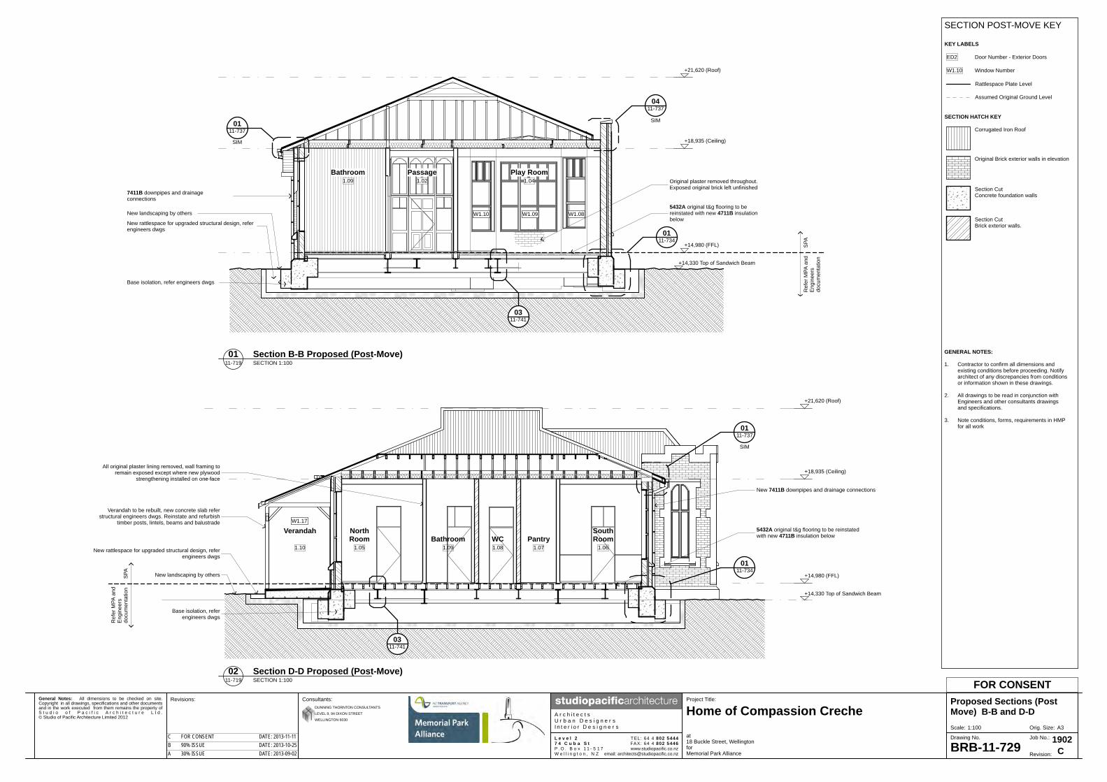
General Notes: All dimensions to be checked on site.Copyright in all drawings, specifications and other documentsand in the work executed from them remains the property ofS t u d i o o f P a c i f i c A r c h i t e c t u r e L t d .© Studio of Pacific Architecture Limited 2012
A3Orig. Size:Scale:
Revisions: Project Title:
BRB-11-729
Proposed Sections (PostMove) B-B and D-D
at18 Buckle Street, WellingtonforMemorial Park Alliance
Consultants:
A r c h i t e c t sU r b a n D e s i g n e r sI n t e r i o r D e s i g n e r s
www.studiopacific.co.nzemail: [email protected]
TEL: 64 4 802 5444FAX: 64 4 802 5446
Home of Compassion Creche
L e v e l 27 4 C u b a S tP . O . B o x 1 1 - 5 1 7W e l l i n g t o n , N Z Revision:
1902Job No.:Drawing No.
FOR CONSENT
DUNNING THORNTON CONSULTANTS
LEVEL 9, 94 DIXON STREET
WELLINGTON 6030
CA 30% ISSUE DATE: 2013-09-02B 90% ISSUE DATE: 2013-10-25C FOR CONSENT DATE: 2013-11-11
0411-737
0111-734
0111-737
+14,330 Top of Sandwich Beam
Play Room1.04
Bathroom1.09
W1.09 W1.08W1.10
Ref
er M
PA a
ndE
ngin
eers
docu
men
tatio
n
SPA
SIM
SIM
+14,980 (FFL)
+18,935 (Ceiling)
+21,620 (Roof)
0311-741
New landscaping by others
New rattlespace for upgraded structural design, referengineers dwgs
7411B downpipes and drainageconnections
5432A original t&g flooring to bereinstated with new 4711B insulationbelow
Base isolation, refer engineers dwgs
Original plaster removed throughout.Exposed original brick left unfinished
Passage1.02
0111-737
0111-734
+14,330 Top of Sandwich Beam
SouthRoom
NorthRoom PantryWCBathroom
Verandah
1.061.071.081.091.05
Ref
er M
PA a
ndE
ngin
eers
docu
men
tatio
nS
PA
SIM
+14,980 (FFL)
+18,935 (Ceiling)
+21,620 (Roof)
0311-741
Verandah to be rebuilt, new concrete slab referstructural engineers dwgs. Reinstate and refurbish
timber posts, lintels, beams and balustrade
New landscaping by others
New rattlespace for upgraded structural design, referengineers dwgs
New 7411B downpipes and drainage connections
5432A original t&g flooring to be reinstatedwith new 4711B insulation below
Base isolation, referengineers dwgs
All original plaster lining removed, wall framing toremain exposed except where new plywood
strengthening installed on one face
1.10
W1.17
SECTION POST-MOVE KEY
KEY LABELS
ED2
W1.10
Door Number - Exterior Doors
Window Number
SECTION HATCH KEY
Corrugated Iron Roof
Rattlespace Plate Level
Assumed Original Ground Level
Original Brick exterior walls in elevation
Section CutConcrete foundation walls
Section CutBrick exterior walls.
GENERAL NOTES:
1. Contractor to confirm all dimensions andexisting conditions before proceeding. Notifyarchitect of any discrepancies from conditionsor information shown in these drawings.
2. All drawings to be read in conjunction with Engineers and other consultants drawings and specifications.
3. Note conditions, forms, requirements in HMPfor all work
01 Section B-B Proposed (Post-Move)SECTION 1:10011-719
02 Section D-D Proposed (Post-Move)SECTION 1:10011-719
1:100

General Notes: All dimensions to be checked on site.Copyright in all drawings, specifications and other documentsand in the work executed from them remains the property ofS t u d i o o f P a c i f i c A r c h i t e c t u r e L t d .© Studio of Pacific Architecture Limited 2012
A3Orig. Size:Scale:
Revisions: Project Title:
BRB-11-730
WC Enlarged Plan andElevations
at18 Buckle Street, WellingtonforMemorial Park Alliance
Consultants:
A r c h i t e c t sU r b a n D e s i g n e r sI n t e r i o r D e s i g n e r s
www.studiopacific.co.nzemail: [email protected]
TEL: 64 4 802 5444FAX: 64 4 802 5446
Home of Compassion Creche
L e v e l 27 4 C u b a S tP . O . B o x 1 1 - 5 1 7W e l l i n g t o n , N Z Revision:
1902Job No.:Drawing No.
FOR CONSENT
DUNNING THORNTON CONSULTANTS
LEVEL 9, 94 DIXON STREET
WELLINGTON 6030
CA 30% ISSUE DATE: 2013-09-02B 90% ISSUE DATE: 2013-10-25C FOR CONSENT DATE: 2013-11-11
4
5
6
3
700
475
5432A reinstated timber floorand plywood diaphragm
D1.07
C L
CL
Existing window to beretained
New 7151A WC
New 7151B basin
Existing door to be reinstated
FRP sheet bracing to wall,refer Engineers dwgs fordetails
FRP sheet bracing to wall,refer Engineers dwgs fordetails15mm plywood on 20mmtimber strapping locallybehind basin to supportbasin
15mm plywood on20mm timber
strapping locallybehind toilet to
support toilet
W1.14
0111-736
1,430 cos
+15,050
+19,005
Existing windowto be retained
New 7151A WC
900x1200mm15mm plywoodon 20mm timberstrapping locallybehind toilet tosupport toilet
Exposed brickwork
W1.14
+15,050
+19,005
1,730 cos
New 7151B basin
600x300mm15mm plywoodon 20mm timberstrapping locallybehind basin tosupport basin
FRP sheetbracing to bothside of wall,refer Engineersdwgs for details
Exposed brickwork
1,430 cos
+15,050
+19,005
Existing door o bereinstated
Framing exposed
D1.07
+15,050
+19,005
1,730 cos
FRP sheetbracing to bothsides of wall,refer Engineersdwgs for details
1,730 cos
1,43
0 co
s
Existing electrical wiring to beretained
Existing pressed metal ceilingto be retained
GENERAL NOTES:
1. Contractor to confirm all dimensions andexisting conditions before proceeding. Notifyarchitect of any discrepancies from conditionsor information shown in these drawings.
2. All drawings to be read in conjunction with Engineers and other consultants drawings and specifications.
3. Note conditions, forms, requirements in HMPfor all work
4 Refer Structural Engineer's dwgs for location ofstrengthening
01 Enlarged WC PlanPLAN 1:2511-719
02 Enlarged WC RCPPLAN 1:2511-720
03 WC ElevationELEVATION 1:25-
04 WC ElevationELEVATION 1:25-
05 WC ElevationELEVATION 1:25-
06 WC ElevationELEVATION 1:25-
1:25

General Notes: All dimensions to be checked on site.Copyright in all drawings, specifications and other documentsand in the work executed from them remains the property ofS t u d i o o f P a c i f i c A r c h i t e c t u r e L t d .© Studio of Pacific Architecture Limited 2012
A3Orig. Size:Scale:
Revisions: Project Title:
BRB 11-734
External Details Foundation
at18 Buckle Street, WellingtonforMemorial Park Alliance
Consultants:
A r c h i t e c t sU r b a n D e s i g n e r sI n t e r i o r D e s i g n e r s
www.studiopacific.co.nzemail: [email protected]
TEL: 64 4 802 5444FAX: 64 4 802 5446
Home of Compassion Creche
L e v e l 27 4 C u b a S tP . O . B o x 1 1 - 5 1 7W e l l i n g t o n , N Z Revision:
1902Job No.:Drawing No.
FOR CONSENT
DUNNING THORNTON CONSULTANTS
LEVEL 9, 94 DIXON STREET
WELLINGTON 6030
CA 30% ISSUE DATE: 2013-09-02B 90% ISSUE DATE: 2013-10-25C FOR CONSENT DATE: 2013-11-11
+14,980
Existing exterior brick leaf, 6710A paintfinish to be removed where indicatedon elevations, mortar joints to be rakedout a min. 25mm and 4261B re-pointedwith mortar mix to match original.
Existing 4911A cast iron vent in exteriorbrick leaf, to be cleaned back and6711C paint finished.
Existing solid plaster skirt overfoundation wall, allow to make 4282Arepairs where required, to matchexisting, cast iron subfloor vents are tobe retained where possible, 4911A cleanback and 6711C paint finish.
New concrete pavers, refer to landscapedrawings and specification for site surfacefinishes detail.
Steel cover plate to rattle space layedover top of new sandwich beam, referto Engineers drawings and specificationfor all subfloor and foundation details.
Line of original solid plasterfinish removed, new FRP
strengthening and Tyfostrips applied to existinginner brick leaf, refer to
Engineers drawings andspecification for all
strengthening detailsLine of existing coved
skirting removed for salvageto enable lifting of floor.
5432A original Matai t&gfloor boards re-laidover new
H3.2 plywood floordiaphragm over new H3.2
joists, refer to Engineersdrawings for joist set out,
plywood and fixing to newsteel beams
Refer to Engineersdrawings for details of new
steel beams to subfloor
Sandwich beam to eitherside of existing concrete
foundations, refer toEngineers drawings
All new timber over 4161BDPC at concrete and
masonry. Refer Engineersdwgs for sub floor structure
Chase formed in top of new sandwichbeam for down pipe drain to rattle space.
4711B underfloor insulation
FFL
Refer Structural Engineer's dwgs for all
foundation and floor fra
ming details
New chase cut into existing concretefoundation wall to accommodate new7411B downpipe location, allow toplaster to match existing.
+14,980
+14,330
+14,400
Existing exterior brick leaf, 6710A paintfinish to be removed where indicated onelevations, mortar joints to be raked outa min. 25mm and 4261B re-pointed withmortar mix to match original.
Existing 4911A cast iron vent in exteriorbrick leaf, to be cleaned back and 6711Cpaint finished.
Existing solid plaster skirt overfoundation wall, allow to make 4282Arepairs where required, to matchexisting, cast iron subfloor vents are tobe retained where possible, 4911A cleanback and 6711C paint finish.
New concrete pavers, refer to landscapedrawings and specification for sitesurface finishes detail.
Steel cover plate to rattle space layedover top of new sandwich beam, referto Engineers drawings and specificationfor all subfloor and foundation details.
Line of original match boardlining up to dado level
removed and salvaged, newFRP strengthening and Tyfo
strips applied to existinginner brick leaf, refer to
Engineers drawings andspecification for all
strengthening details
Refer to Engineersdrawings for details of new
steel beams to subfloor
Sandwich beam to eitherside of existing concrete
foundations, refer toEngineers drawings
Line of existing covedskirting removed and
salvaged to enable lifting offloor.
Line of existing ceramic tilesremoved, allow for depth ofnew tiles & grout over new
slab topping to level withFFL
New concrete slab, refer toEngineers drawings for
details
FFL
Porch1.01
Refer Structural Engineer's dwgs for all
foundation and floor fra
ming details
GENERAL NOTES:
1. Contractor to confirm all dimensions andexisting conditions before proceeding. Notifyarchitect of any discrepancies from conditionsor information shown in these drawings.
2. All drawings to be read in conjunction with Engineers and other consultants drawings and specifications.
3. Note conditions, forms, requirements in HMPfor all work
01 Foundation Detail - TypicalDETAIL 1:1011-719
02 Foundation Detail - PorchDETAIL 1:1011-719
1:10

General Notes: All dimensions to be checked on site.Copyright in all drawings, specifications and other documentsand in the work executed from them remains the property ofS t u d i o o f P a c i f i c A r c h i t e c t u r e L t d .© Studio of Pacific Architecture Limited 2012
A3Orig. Size:Scale:
Revisions: Project Title:
BRB 11-735
External Details Foundation
at18 Buckle Street, WellingtonforMemorial Park Alliance
Consultants:
A r c h i t e c t sU r b a n D e s i g n e r sI n t e r i o r D e s i g n e r s
www.studiopacific.co.nzemail: [email protected]
TEL: 64 4 802 5444FAX: 64 4 802 5446
Home of Compassion Creche
L e v e l 27 4 C u b a S tP . O . B o x 1 1 - 5 1 7W e l l i n g t o n , N Z Revision:
1902Job No.:Drawing No.
FOR CONSENT
DUNNING THORNTON CONSULTANTS
LEVEL 9, 94 DIXON STREET
WELLINGTON 6030
CA 30% ISSUE DATE: 2013-09-02B 90% ISSUE DATE: 2013-10-25C FOR CONSENT DATE: 2013-11-11
+14,980
+14,330
+14,400
145
145
145
145
Existing solid plaster skirt over foundationwall, allow to make 4282A repairs whererequired, to match existing, 4911A castiron subfloor vents are to be retainedwhere possible, clean back and 6711Cpaint finish.
New concrete pavers, refer to landscapedrawings and specification for site surfacefinishes detail.
Steel cover plate to rattle space layedover top of new sandwich beam, referto Engineers drawings and specificationfor all subfloor and foundation details.
Sandwich beam to either side of existingconcrete foundations,
refer to Engineers drawings
Line of original match boardlining up to dado level removed and
salvaged, new FRP strengthening andTyfo strips applied to existing inner
brick leaf, refer to Engineers drawingsand specification for all strengthening
details
Line of existing coved skirtingremoved and salvaged to enable lifting
of floor.Line of existing ceramic tiles removed,
allow for depth of new tiles & groutover new slab topping to level with FFL
New concrete slab,refer to Engineers drawings for details
New concrete steps formed with 4282Aplaster finish to match original. Refer toEngineers drawings for detailsof reinforcing placement
New 4962A water bar set intoepoxy grout to edge of tiled floor area,to full width of door opening.
FFL
Refer Structural Engineer's dwgs for all
foundation and floor fra
ming details
GENERAL NOTES:
1. Contractor to confirm all dimensions andexisting conditions before proceeding. Notifyarchitect of any discrepancies from conditionsor information shown in these drawings.
2. All drawings to be read in conjunction with Engineers and other consultants drawings and specifications.
3. Note conditions, forms, requirements in HMPfor all work
01 Foundation Detail - PorchDETAIL 1:1011-719
1:10

General Notes: All dimensions to be checked on site.Copyright in all drawings, specifications and other documentsand in the work executed from them remains the property ofS t u d i o o f P a c i f i c A r c h i t e c t u r e L t d .© Studio of Pacific Architecture Limited 2012
A3Orig. Size:Scale:
Revisions: Project Title:
BRB 11-736
External Details Foundation
at18 Buckle Street, WellingtonforMemorial Park Alliance
Consultants:
A r c h i t e c t sU r b a n D e s i g n e r sI n t e r i o r D e s i g n e r s
www.studiopacific.co.nzemail: [email protected]
TEL: 64 4 802 5444FAX: 64 4 802 5446
Home of Compassion Creche
L e v e l 27 4 C u b a S tP . O . B o x 1 1 - 5 1 7W e l l i n g t o n , N Z Revision:
1902Job No.:Drawing No.
FOR CONSENT
DUNNING THORNTON CONSULTANTS
LEVEL 9, 94 DIXON STREET
WELLINGTON 6030
CA 30% ISSUE DATE: 2013-09-02B 90% ISSUE DATE: 2013-10-25C FOR CONSENT DATE: 2013-11-11
+14,980
+14,400
+ confirm on Engineers drawings
Existing solid plaster skirt over foundation wall,allow to make 4282A repairs where required,to match existing, cast iron subfloor vents areto be retained where possible, 4911A cleanback and 6711C paint finish.
New concrete pavers, refer to landscapedrawings and specification for site surfacefinishes detail.
Steel cover plate to rattle space layedover top of new sandwich beam, referto Engineers drawings and specificationfor all subfloor and foundation details.
5432A original Matai t&g floor boards re-laidover new H3.2 plywood floor diaphragm overnew H3.2 joists, refer to Engineers drawings
for joist set out and fixing to new steel beams
Refer to Engineers drawings fordetails of new steel beams to
subfloor
Sandwich beam to either side of existingconcrete foundations,
refer to Engineers drawings
4711B underfloor insulation
New waste trap to WC taken throughfloor and around sandwich beam. Refer
MPA dwgs
All new timber over 4161BDPC at concrete and
masonry. Refer Engineersdwgs for sub floor structure
FFL
Refer Structural Engineer's dwgs for all
foundation and floor fra
ming details
GENERAL NOTES:
1. Contractor to confirm all dimensions andexisting conditions before proceeding. Notifyarchitect of any discrepancies from conditionsor information shown in these drawings.
2. All drawings to be read in conjunction with Engineers and other consultants drawings and specifications.
3. Note conditions, forms, requirements in HMPfor all work
01 Foundation Detail - WCDETAIL 1:1011-719
1:10

General Notes: All dimensions to be checked on site.Copyright in all drawings, specifications and other documentsand in the work executed from them remains the property ofS t u d i o o f P a c i f i c A r c h i t e c t u r e L t d .© Studio of Pacific Architecture Limited 2012
A3Orig. Size:Scale:
Revisions: Project Title:
BRB 11-737
External Details Roof
at18 Buckle Street, WellingtonforMemorial Park Alliance
Consultants:
A r c h i t e c t sU r b a n D e s i g n e r sI n t e r i o r D e s i g n e r s
www.studiopacific.co.nzemail: [email protected]
TEL: 64 4 802 5444FAX: 64 4 802 5446
Home of Compassion Creche
L e v e l 27 4 C u b a S tP . O . B o x 1 1 - 5 1 7W e l l i n g t o n , N Z Revision:
1902Job No.:Drawing No.
FOR CONSENT
DUNNING THORNTON CONSULTANTS
LEVEL 9, 94 DIXON STREET
WELLINGTON 6030
CA 30% ISSUE DATE: 2013-09-02B 90% ISSUE DATE: 2013-10-25C FOR CONSENT DATE: 2013-11-11
New 7411A gutter on concealed bracketson existing fascia, with 6711A paint finish.
Existing t&g soffit lining, 4221A repair/replaceand 6711A repaint to match existing.
Existing exterior brick leaf, 6710A paint finish to beremoved where indicated on elevations,mortar joints to be raked out a min. 25mmand 4261B re-pointed with mortar mix to match original.
Existing solid plaster, 6710A paint finish to be removed,4282A repair to match existing.
Existing cast iron cavity vent, 4911A repair and 6711C repaint.
New 4311B corrugated roofingover new 4161D underlay on existingsarking, reuse removed sarking wheresuitable, otherwise allow to replace withH3.1 treated RS pine boards to match insize where original are removed foraccess to lay new ply diaphragm
New plywood diaphragm overexisting ceiling joists, refer to Engineersdrawings for details.
Existing pressed metal ceiling retained.
Line of original solid plaster finishremoved, new FRP strengtheningand Tyfo strips applied to existinginner brick leaf, refer to Engineersdrawings and specification for all
strengthening details
New 4711A insulation
150
150
50
Line of original solid plaster finishremoved, new FRP strengtheningand Tyfo strips applied to existinginner brick leaf, refer to Engineersdrawings and specification for allstrengthening detailsExisting exterior brick leaf, 6710A paint
finish to be removed where indicated onelevations, mortar joints to be raked out a
min. 25mm and 4261B re-pointed withmortar mix to match original.
New 7411A gutteron concealed
brackets on existingfascia, with 6711A
paint finish.
4221A refurbish original t&g soffit lining iffound under demolished lining, with 6711Afinish. Otherwise allow to fit new (4221B &
6711B)
New 4311C roll seamed 'Eurostyle' trayroofingover new 4161D underlay and
plywood sarking, original roof claddingremoved. Sarking over timber furring to
min. 2 degree fall
New 4311B corrugated roofingover new 4161D underlay on existing
sarking, reuse removed sarking wheresuitable, otherwise allow to replace withH3.1 treated RS pine boards to matchin size where original are removed foraccess to lay new ply diaphragm
New folded metal flashing at changeof pitch and profile.
New plywood sarking over existingceiling joists. Refer to Engineers details
Existing plaster board ceiling retained
New 4711A insulation
400 East Gutter
90 m
in
+19.370
+19.490
New 4311B corrugated roofingover new 4161D underlay on existingsarking, reuse removed sarking wheresuitable, otherwise allow to replace withH3.1 treated RS pine boards to match insize where original are removed for accessto lay new ply diaphragm
New plywood diaphragm overexisting ceiling joists, refer to Engineersdrawings for details.
Existing ceiling lining retained.
Line of original solid plaster finishremoved, new Tyfo strips applied to existinginner brick leaf, refer to Engineersdrawings and specification for allstrengthening details
New 4422A membrane roofing over4337A plywood underlay to fall overfurring battens on new plywooddiaphragm, refer Engineers dwgs fordiaphragm details. Membrane to carry upraking roof to allow 90mm min heightabove gutter at highest point.
New 4422A membrane taken up face ofparapet wall, new folded steel flashing setinto chase with min. 150mm lap, groutand seal with sealant.
Existing exterior brick leaf, 6710A paintfinish to be removed where indicated onelevations, mortar joints to be raked out amin. 25mm and 4261B re-pointed withmortar mix to match original.
Existing solid plaster capering retained
Section of existing ceiling liningremoved for access to joist endsand gutter.Provide blocking to support edge.
Existing rafters retained, cut back tosuit widening of channel gutter and blockoff existing ceiling joists.Refer to Engineers drawings for fixingsto diaphragm.
4711A insulation
low point
high point
Refer Structural Engineer's
dwgs for roof framing
GENERAL NOTES:
1. Contractor to confirm all dimensions andexisting conditions before proceeding. Notifyarchitect of any discrepancies from conditionsor information shown in these drawings.
2. All drawings to be read in conjunction with Engineers and other consultants drawings and specifications.
3. Note conditions, forms, requirements in HMPfor all work
01 Eave Detail - TypicalDETAIL 1:1011-728
02 Bay Roof DetailDETAIL 1:1011-728
04 Internal Gutter DetailDETAIL 1:1011-729
03 Bay Roof DetailDETAIL 1:1011-728
1:10

General Notes: All dimensions to be checked on site.Copyright in all drawings, specifications and other documentsand in the work executed from them remains the property ofS t u d i o o f P a c i f i c A r c h i t e c t u r e L t d .© Studio of Pacific Architecture Limited 2012
A3Orig. Size:Scale:
Revisions: Project Title:
BRB 11-738
External Details Roof
at18 Buckle Street, WellingtonforMemorial Park Alliance
Consultants:
A r c h i t e c t sU r b a n D e s i g n e r sI n t e r i o r D e s i g n e r s
www.studiopacific.co.nzemail: [email protected]
TEL: 64 4 802 5444FAX: 64 4 802 5446
Home of Compassion Creche
L e v e l 27 4 C u b a S tP . O . B o x 1 1 - 5 1 7W e l l i n g t o n , N Z Revision:
1902Job No.:Drawing No.
FOR CONSENT
DUNNING THORNTON CONSULTANTS
LEVEL 9, 94 DIXON STREET
WELLINGTON 6030
CA 30% ISSUE DATE: 2013-09-02B 90% ISSUE DATE: 2013-10-25C FOR CONSENT DATE: 2013-11-11
250
10035
110
130
9027
016
0
150
30025
25
75
850
O/A
cos
New metal flashing with lapof 250mm to roofing.
4261A brick-slip veneer adhesivefixed over 4231A fibre cement sheet
fixed to 20mm cavity battens over4231D RAB fixed in accordance with
manufacturers requirements. RABtaken down to ceiling diaphragm
New timber framing from ceilingjoists and above to form exterior
chimney suitable for future flue fromnew fireplace, fireplace by others.
New 4311B corrugated roofing over new 4161Dunderlay on existing sarking.
New metal flashing with lap of 200mm toroofing.
4261A brick-slip veneer adhesive fixed over4231A fibre cement sheet fixed to cavity battensin accordance with manufacturers requirements
Nominal 20mm cavity, 4231D RAB to continuedown to ceiling diaphragm over new H3.1framing.
4261A brick-slip veneer adhesive fixed over4231A fibre cement sheet fixed to 20mmcavity battens over 4231D RAB fixedin accordance with manufacturersrequirements.
Shaped 4238A AAC panel fixed over4231A fibre cement sheet on cavitybattens fixed to framing in accordancewith manufacturers requirements on4231D RAB
Existing salvaged terracotta chimney potsto be re-used, provide bird proofing.
New stainless chimney capping by others,provide temporary cowl inside of pots forweather protection.
Lightweight 4238A AAC shaped to match existingchimney capping, direct fixed over 4231A fibrecement sheet on 20mm cavity battens.4282A plaster over, finish to match existingplaster.
100x100mm louvered vent through tochimney cavity.
Galv. 75x50x6 EA to all four sides of opening,M8 coach screw to framing @ 150crs andto ACC capping.
S/S flashing cover to capping
S/S lugs 65mm H x 30mm W welded tocapping at 100mm intervals aroundbase of salvage chimney pot beddedon dobbs of sealant to allow drainage,secured with 6mm dia. s/s braidedwire tensioned around
Note:Confirm all dimensions of existing chimneyincluding profiles prior to demolition. The chimneyis to be rebuilt to match existing (the overalllength and width may vary)
20
New 4311B corrugatedroofing over new 4161D
underlay on existing sarking.
Allow to trim existing opening whereoriginal brick chimney passed through,
to suit new timber framed and cladreplica chimney
Allow to trim existing opening where originalbrick chimney passed through, to suitnew timber framed and clad replica chimney
Existing rafters and sarking over
New ply panel, refer engineer's dwgs
New ply panel, refer engineer's dwgs
110
90
2 crests cover
Galv. steel flashing with lap of200mm to roofing.
New 4221C profiled weatherboards direct fixedover bird netting to existing gable roofframing, profile to match existing,6711B paint finish.
New bird netting lining fixed to existing gabletframing
New 4221B t&g soffit to existing eave,to match existing, 6711B paint finish.
Existing barge board retained, repairand repaint as required.
New folded galv. steel barge flashing.
Galvanised corrugated roofing 4311Bover new 4161D underlay on existing sarking,new 3821G sarking whereoriginal removed for access to laydiaphragm
Galvanised corrugated roofing 4311Bover new underlay on existing sarking.
Allow to trim existing opening where originalbrick chimney passed through, to suitnew timber framed and clad replica chimney
Existing rafters and sarking over
Existing gablet framing retained,strengthen & make repairs as required.
GENERAL NOTES:
1. Contractor to confirm all dimensions andexisting conditions before proceeding. Notifyarchitect of any discrepancies from conditionsor information shown in these drawings.
2. All drawings to be read in conjunction with Engineers and other consultants drawings and specifications.
3. Note conditions, forms, requirements in HMPfor all work
2 crests cover
90
New H3.2 radiata vertical weatherboards with rag end detail to matchexisting, direct fix to existing framing,paint finish.
Existing t&g soffit to eave,prepare and paint finish.
Existing barge board retained,repair and repaint as required.
New folded galv. steel barge flashing.
Galvanised corrugated roofing4311B over new 4161D underlayon existing sarking,new 3821Gsarking where original removed foraccess to laydiaphragm
Existing timber beam retained inplace, strip back, prepare andrepaint.
Existing timber framing retained inplace, repair/strengthen as required.
Existing internal lining retained,prepare and repaint.
01 Chimney DetailDETAIL 1:1011-724
03 Chimney DetailDETAIL 1:1011-724
04 North Gablet DetailDETAIL 1:1011-724
02 Chimney DetailDETAIL 1:1011-724
05 Verandah DetailDETAIL 1:1011-728
1:10

General Notes: All dimensions to be checked on site.Copyright in all drawings, specifications and other documentsand in the work executed from them remains the property ofS t u d i o o f P a c i f i c A r c h i t e c t u r e L t d .© Studio of Pacific Architecture Limited 2012
A3Orig. Size:Scale:
Revisions: Project Title:
BRB 11-739
External Details - Windows
at18 Buckle Street, WellingtonforMemorial Park Alliance
Consultants:
A r c h i t e c t sU r b a n D e s i g n e r sI n t e r i o r D e s i g n e r s
www.studiopacific.co.nzemail: [email protected]
TEL: 64 4 802 5444FAX: 64 4 802 5446
Home of Compassion Creche
L e v e l 27 4 C u b a S tP . O . B o x 1 1 - 5 1 7W e l l i n g t o n , N Z Revision:
1902Job No.:Drawing No.
FOR CONSENT
DUNNING THORNTON CONSULTANTS
LEVEL 9, 94 DIXON STREET
WELLINGTON 6030
CA 30% ISSUE DATE: 2013-09-02B 90% ISSUE DATE: 2013-10-25C FOR CONSENT DATE: 2013-11-11
New sliding sash window with top lightto match original, existing non-originalwindow removed from opening.New sliding sash window with top light
to match original, existing non-originalwindow removed from opening.
Line of existing solid plasterremoved from interior
New casement window with top lightto match original, existing non-originalwindow removed from opening.
Sill on H3.2 packer on DPVPEF rod and sealant between sillpiece and plaster
Existing solid plaster sill to openingallow to make repairs around all fourside of opening where effected bywindow removel
Line of existing solid plasterremoved from interior
Existing solid plaster reveal to openingallow to make repairs around all four sideof opening where effected by windowremovel, PEF rod and sealant betweentimber and plaster stopping bead
New top casement window to matchoriginal, new hardware to be as perschedule
Vertical line of sealant to jamb
H3.2 packer on DPC
Existing solid plaster sill to openingallow to make repairs around all fourside of opening where effected bywindow removel
Sill on H3.2 packer on DPVPEF rod and sealant between sillpiece and plaster
Top casement window to matchoriginal, new hardware to be as perschedule
Existing solid plasterreveal to opening allow tomake repairs around allfour side of opening whereeffected by windowremovel, PEF rod andsealant between timberand plaster stopping bead
Rebated mullion
Existing solid plaster reveal toopening allow to make repairsaround all four side of opening
where effected by windowremovel, PEF rod and sealant
between timber and plasterstopping bead
Existing solid plaster reveal to openingallow to make repairs around all four sideof opening where effected by windowremovel, PEF rod and sealant betweentimber and plaster stopping bead
Existing sash weights to be fitted withnew cords, ensure all sliding sashesare fully operable
GENERAL NOTES:
1. Contractor to confirm all dimensions andexisting conditions before proceeding. Notifyarchitect of any discrepancies from conditionsor information shown in these drawings.
2. All drawings to be read in conjunction with Engineers and other consultants drawings and specifications.
3. Note conditions, forms, requirements in HMPfor all work
02 Casement Window SillDETAIL 1:511-747
01 Casement Window HeadDETAIL 1:511-747
06 Double Hung Sash Window SillDETAIL 1:511-746
03 Casement Window JambDETAIL 1:511-747
04 Double Hung Sash Window JambDETAIL 1:511-746
05 Double Hung Sash Window HeadDETAIL 1:511-746
1:5

General Notes: All dimensions to be checked on site.Copyright in all drawings, specifications and other documentsand in the work executed from them remains the property ofS t u d i o o f P a c i f i c A r c h i t e c t u r e L t d .© Studio of Pacific Architecture Limited 2012
A3Orig. Size:Scale:
Revisions: Project Title:
BRB 11-741
Internal Details
at18 Buckle Street, WellingtonforMemorial Park Alliance
Consultants:
A r c h i t e c t sU r b a n D e s i g n e r sI n t e r i o r D e s i g n e r s
www.studiopacific.co.nzemail: [email protected]
TEL: 64 4 802 5444FAX: 64 4 802 5446
Home of Compassion Creche
L e v e l 27 4 C u b a S tP . O . B o x 1 1 - 5 1 7W e l l i n g t o n , N Z Revision:
1902Job No.:Drawing No.
FOR CONSENT
DUNNING THORNTON CONSULTANTS
LEVEL 9, 94 DIXON STREET
WELLINGTON 6030
CA 30% ISSUE DATE: 2013-09-02B 90% ISSUE DATE: 2013-10-25C FOR CONSENT DATE: 2013-11-11
5432A original Matai t&g floor boards re-laidover new H3.2 plywood floordiaphragm over new H3.2 joists,refer to Engineers drawings for joistset out and fixing to new steel beams.
-71,248,474
New 4711B insulation between floorjoists.
New in situ lightweight concrete hearthto fire place to match existing, by others.
GENERAL NOTES:
1. Contractor to confirm all dimensions andexisting conditions before proceeding. Notifyarchitect of any discrepancies from conditionsor information shown in these drawings.
2. All drawings to be read in conjunction with Engineers and other consultants drawings and specifications.
3. Note conditions, forms, requirements in HMPfor all work
Existing timber lath and plasterto be removed.
Existing 1/2 round timberarchitrave removed and salvaged.
Line of existing coved skirtingremoved to enable lifting of floor.
Existing door frame retained.
Existing door removedand salvaged.
Carpet protection cover toretained door frame overtemporary packing.
New plywood bracing panelto existing framing, refer Engineersdwgs. Provide temporary packingover.
Temporary packing forfixing of protection.
03 Floor DetailSECTION DETAIL 1:511-719
01 Door to Wall Detail DemolitionPLAN DETAIL 1:511-716
02 Door to Wall Detail Proposed Post-MovePLAN DETAIL 1:511-719
1:5

General Notes: All dimensions to be checked on site.Copyright in all drawings, specifications and other documentsand in the work executed from them remains the property ofS t u d i o o f P a c i f i c A r c h i t e c t u r e L t d .© Studio of Pacific Architecture Limited 2012
A3Orig. Size:Scale:
Revisions: Project Title:
BRB-11-743
Door Schedule
at18 Buckle Street, WellingtonforMemorial Park Alliance
Consultants:
A r c h i t e c t sU r b a n D e s i g n e r sI n t e r i o r D e s i g n e r s
www.studiopacific.co.nzemail: [email protected]
TEL: 64 4 802 5444FAX: 64 4 802 5446
Home of Compassion Creche
L e v e l 27 4 C u b a S tP . O . B o x 1 1 - 5 1 7W e l l i n g t o n , N Z Revision:
1902Job No.:Drawing No.
FOR CONSENT
DUNNING THORNTON CONSULTANTS
LEVEL 9, 94 DIXON STREET
WELLINGTON 6030
CA 30% ISSUE DATE: 2013-09-02B 90% ISSUE DATE: 2013-10-25C FOR CONSENT DATE: 2013-11-11
Elevation
3,79
0 co
s
2,15
0 co
s1,
640
cos
970 cos
3,66
0 co
s
2,14
5 co
s1,
515
cos
2,400 cos
710 cos 980 cos 710 cos
Door ID ED1 ED2
Handing R R
Location East North inside verandah
Quantity 1 1
Leaf Dimensions 900x2,150 980x2,145
Frame Existing to be refurbished Existing to be refurbished
Glazing n/a Existing retained. New glazing in top panels where missing to match existing(shown shaded)
Finish/ColourHardware Set New doorset (A) and mortice lock (B) New doorset (A) and mortice lock (B)
Security Requirements
Note/Remarks Check all dimensions on site Check all dimensions on site
ED1
ED2
ED3
Painted timber glazed and panelled doorwith gothic traceried toplights hardwareand furniture, joints parting, loose andmissing furniture
D1.01
D1.02
D1.03D1.04
D1.05
D1.06
D1.07
D1.08D1.09
EXISTING DOOR CONDITION
Painted timber four panel door, wornpaintwork with hardware, furnituremissing
Painted timber four panel doorMissing door
Painted timber panelled door, wornpaintwork
Painted timber panelled door, loose doorhardware
Painted timber panelled door, loose andmissing door hardware
Door missing
Painted timber panelled and glazed withpanelled and glazed sidelights and triplegothic casement trefoil, loose andmissing furniturePainted timber panelled door, missingpanel, worn paintwork
Painted timber glazed with panelled doorwith Gothic traceried toplights, hardwareand furniture. Joints parting, paintpeeling off all joinery
Painted timber panelled door, wornpaintwork
GENERAL NOTES:1. Contractor to confirm all dimensions and
existing conditions before proceeding. Notifyarchitect of any discrepancies from conditionsor information shown in these drawings.
2. All drawings to be read in conjunction with Engineers and other consultants drawings and specifications.
3. Note conditions, forms, requirements in HMPfor all work
4. Existing doors to be retained and refurbishedinside and outside, made fully operable, hingeschecked and replaced if inoperable
NEW DOOR AND WINDOWHARDWARE
Windsor 3002L Victorian Knob Lock,Polished Brass finish (PB)
A
Windsor Lever Locks 57mm Backset, 5Lever, Black Iron finish (BLK)
B
Windsor 5184 350mm Casement Stays,Polished Brass finish (PB)
C
Windsor 5025 Round Sash Fastener,Polished Brass finish (PB)
D
Windsor 5026 Sash Lift Hook, PolishedBrass finish (PB)
E
Windsor 5197 Window Pulley122x25mm, Polished Brass finish (PB)
F
G Windsor 5155 Flush Rings 63x50mm,Polished Brass finish (PB)
900
900
1:50
D1.10
Floor Hatch
Bathroom Lobby
1
900x900
Existing timber flooring on timber frame and ply below
n/a
New flush pulls (G)
Check all dimensions on site
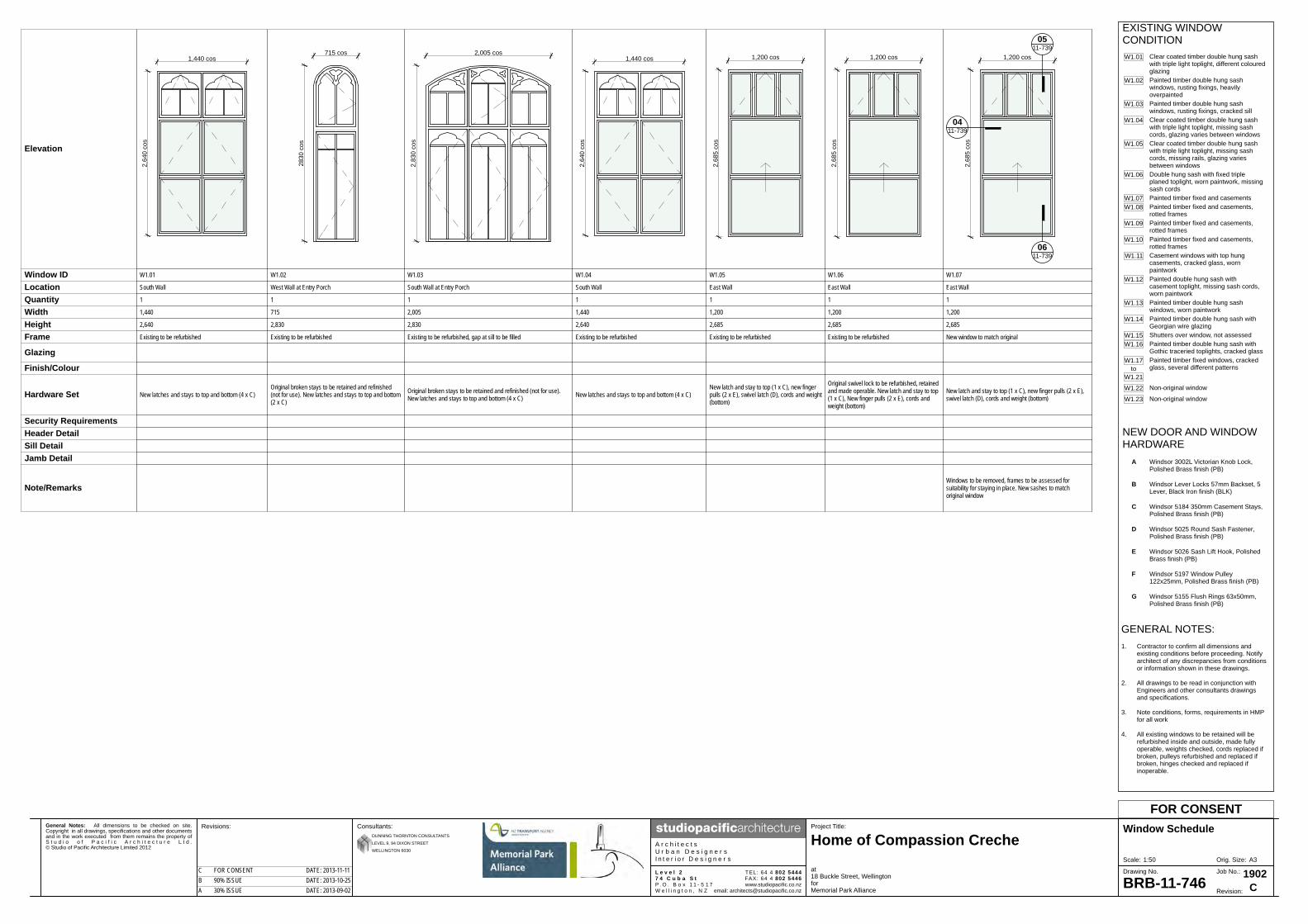
General Notes: All dimensions to be checked on site.Copyright in all drawings, specifications and other documentsand in the work executed from them remains the property ofS t u d i o o f P a c i f i c A r c h i t e c t u r e L t d .© Studio of Pacific Architecture Limited 2012
A3Orig. Size:Scale:
Revisions: Project Title:
BRB-11-746
Window Schedule
at18 Buckle Street, WellingtonforMemorial Park Alliance
Consultants:
A r c h i t e c t sU r b a n D e s i g n e r sI n t e r i o r D e s i g n e r s
www.studiopacific.co.nzemail: [email protected]
TEL: 64 4 802 5444FAX: 64 4 802 5446
Home of Compassion Creche
L e v e l 27 4 C u b a S tP . O . B o x 1 1 - 5 1 7W e l l i n g t o n , N Z Revision:
1902Job No.:Drawing No.
FOR CONSENT
DUNNING THORNTON CONSULTANTS
LEVEL 9, 94 DIXON STREET
WELLINGTON 6030
CA 30% ISSUE DATE: 2013-09-02B 90% ISSUE DATE: 2013-10-25C FOR CONSENT DATE: 2013-11-11
Elevation
1,440 cos
2,64
0 co
s
2830
cos
715 cos
2,83
0 co
s
2,005 cos
2,64
0 co
s
1,440 cos 1,200 cos
2,68
5 co
s
1,200 cos
2,68
5 co
s
1,200 cos
2,68
5 co
s
0411-739
0511-739
0611-739
Window ID W1.01 W1.02 W1.03 W1.04 W1.05 W1.06 W1.07
Location South Wall West Wall at Entry Porch South Wall at Entry Porch South Wall East Wall East Wall East Wall
Quantity 1 1 1 1 1 1 1
Width 1,440 715 2,005 1,440 1,200 1,200 1,200
Height 2,640 2,830 2,830 2,640 2,685 2,685 2,685
Frame Existing to be refurbished Existing to be refurbished Existing to be refurbished, gap at sill to be filled Existing to be refurbished Existing to be refurbished Existing to be refurbished New window to match original
Glazing
Finish/Colour
Hardware Set New latches and stays to top and bottom (4 x C)Original broken stays to be retained and refinished(not for use). New latches and stays to top and bottom(2 x C)
Original broken stays to be retained and refinished (not for use).New latches and stays to top and bottom (4 x C) New latches and stays to top and bottom (4 x C)
New latch and stay to top (1 x C), new fingerpulls (2 x E), swivel latch (D), cords and weight(bottom)
Original swivel lock to be refurbished, retainedand made operable. New latch and stay to top(1 x C), New finger pulls (2 x E), cords andweight (bottom)
New latch and stay to top (1 x C), new finger pulls (2 x E),swivel latch (D), cords and weight (bottom)
Security RequirementsHeader DetailSill DetailJamb Detail
Note/RemarksWindows to be removed, frames to be assessed forsuitability for staying in place. New sashes to matchoriginal window
W1.01
W1.02
W1.03
W1.04
W1.05
W1.06
W1.07W1.08
W1.09
W1.10
W1.11
W1.12
W1.13
W1.14
W1.15W1.16
Painted timber double hung sashwindows, rusting fixings, heavilyoverpaintedPainted timber double hung sashwindows, rusting fixings, cracked sillClear coated timber double hung sashwith triple light toplight, missing sashcords, glazing varies between windowsClear coated timber double hung sashwith triple light toplight, missing sashcords, missing rails, glazing variesbetween windows
Clear coated timber double hung sashwith triple light toplight, different colouredglazing
Painted timber double hung sash withGothic traceried toplights, cracked glass
Shutters over window, not assessed
Painted timber double hung sash withGeorgian wire glazing
Painted timber double hung sashwindows, worn paintwork
Painted double hung sash withcasement toplight, missing sash cords,worn paintwork
Casement windows with top hungcasements, cracked glass, wornpaintwork
Double hung sash with fixed tripleplaned toplight, worn paintwork, missingsash cordsPainted timber fixed and casementsPainted timber fixed and casements,rotted framesPainted timber fixed and casements,rotted framesPainted timber fixed and casements,rotted frames
W1.17 Painted timber fixed windows, crackedglass, several different patterns
W1.21to
W1.22
W1.23
Non-original window
Non-original window
EXISTING WINDOWCONDITION
GENERAL NOTES:1. Contractor to confirm all dimensions and
existing conditions before proceeding. Notifyarchitect of any discrepancies from conditionsor information shown in these drawings.
2. All drawings to be read in conjunction with Engineers and other consultants drawings and specifications.
3. Note conditions, forms, requirements in HMPfor all work
4. All existing windows to be retained will berefurbished inside and outside, made fullyoperable, weights checked, cords replaced ifbroken, pulleys refurbished and replaced ifbroken, hinges checked and replaced ifinoperable.
NEW DOOR AND WINDOWHARDWARE
Windsor 3002L Victorian Knob Lock,Polished Brass finish (PB)
A
Windsor Lever Locks 57mm Backset, 5Lever, Black Iron finish (BLK)
B
D
C
E
F Windsor 5197 Window Pulley122x25mm, Polished Brass finish (PB)
Windsor 5026 Sash Lift Hook, PolishedBrass finish (PB)
Windsor 5025 Round Sash Fastener,Polished Brass finish (PB)
Windsor 5184 350mm Casement Stays,Polished Brass finish (PB)
G Windsor 5155 Flush Rings 63x50mm,Polished Brass finish (PB)
1:50
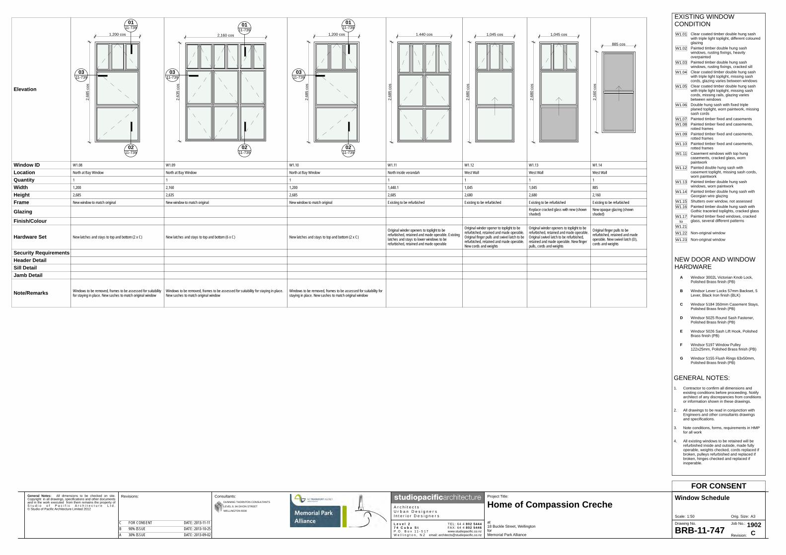
General Notes: All dimensions to be checked on site.Copyright in all drawings, specifications and other documentsand in the work executed from them remains the property ofS t u d i o o f P a c i f i c A r c h i t e c t u r e L t d .© Studio of Pacific Architecture Limited 2012
A3Orig. Size:Scale:
Revisions: Project Title:
BRB-11-747
Window Schedule
at18 Buckle Street, WellingtonforMemorial Park Alliance
Consultants:
A r c h i t e c t sU r b a n D e s i g n e r sI n t e r i o r D e s i g n e r s
www.studiopacific.co.nzemail: [email protected]
TEL: 64 4 802 5444FAX: 64 4 802 5446
Home of Compassion Creche
L e v e l 27 4 C u b a S tP . O . B o x 1 1 - 5 1 7W e l l i n g t o n , N Z Revision:
1902Job No.:Drawing No.
FOR CONSENT
DUNNING THORNTON CONSULTANTS
LEVEL 9, 94 DIXON STREET
WELLINGTON 6030
CA 30% ISSUE DATE: 2013-09-02B 90% ISSUE DATE: 2013-10-25C FOR CONSENT DATE: 2013-11-11
2,68
5 co
s
1,200 cos
0311-739
0111-739
0211-739
2,63
5 co
s
2,160 cos
0311-739
0111-739
0211-739
2,68
5 co
s
1,200 cos
0311-739
0111-739
0211-739
1.440 cos
2,68
5 co
s
1,045 cos
2,68
0 co
s
2,68
0 co
s
1,045 cos
2,16
0 co
s
885 cos
W1.08 W1.09 W1.10 W1.11 W1.12 W1.13 W1.14
North at Bay Window North at Bay Window North at Bay Window North inside verandah West Wall West Wall West Wall
1 1 1 1 1 1 1
1,200 2,160 1,200 1,440.1 1,045 1,045 885
2,685 2,635 2,685 2,685 2,680 2,680 2,160
New window to match original New window to match original New window to match original Existing to be refurbished Existing to be refurbished Existing to be refurbished Existing to be refurbished
Replace cracked glass with new (shownshaded)
New opaque glazing (shownshaded)
New latches and stays to top and bottom (2 x C) New latches and stays to top and bottom (6 x C) New latches and stays to top and bottom (2 x C)
Original winder openers to toplight to berefurbished, retained and made operable. Existinglatches and stays to lower windows to berefurbished, retained and made operable
Original winder opener to toplight to berefurbished, retained and made operable.Original finger pulls and swivel latch to berefurbished, retained and made operable.New cords and weights
Original winder openers to toplight to berefurbished, retained and made operable.Original swivel latch to be refurbished,retained and made operable. New fingerpulls, cords and weights
Original finger pulls to berefurbished, retained and madeoperable. New swivel latch (D),cords and weights
Windows to be removed, frames to be assessed for suitabilityfor staying in place. New sashes to match original window
Windows to be removed, frames to be assessed for suitability for staying in place.New sashes to match original window
Windows to be removed, frames to be assessed for suitability forstaying in place. New sashes to match original window
W1.01
W1.02
W1.03
W1.04
W1.05
W1.06
W1.07W1.08
W1.09
W1.10
W1.11
W1.12
W1.13
W1.14
W1.15W1.16
Painted timber double hung sashwindows, rusting fixings, heavilyoverpaintedPainted timber double hung sashwindows, rusting fixings, cracked sillClear coated timber double hung sashwith triple light toplight, missing sashcords, glazing varies between windowsClear coated timber double hung sashwith triple light toplight, missing sashcords, missing rails, glazing variesbetween windows
Clear coated timber double hung sashwith triple light toplight, different colouredglazing
Painted timber double hung sash withGothic traceried toplights, cracked glass
Shutters over window, not assessed
Painted timber double hung sash withGeorgian wire glazing
Painted timber double hung sashwindows, worn paintwork
Painted double hung sash withcasement toplight, missing sash cords,worn paintwork
Casement windows with top hungcasements, cracked glass, wornpaintwork
Double hung sash with fixed tripleplaned toplight, worn paintwork, missingsash cordsPainted timber fixed and casementsPainted timber fixed and casements,rotted framesPainted timber fixed and casements,rotted framesPainted timber fixed and casements,rotted frames
W1.17 Painted timber fixed windows, crackedglass, several different patterns
W1.21to
W1.22
W1.23
Non-original window
Non-original window
EXISTING WINDOWCONDITION
GENERAL NOTES:1. Contractor to confirm all dimensions and
existing conditions before proceeding. Notifyarchitect of any discrepancies from conditionsor information shown in these drawings.
2. All drawings to be read in conjunction with Engineers and other consultants drawings and specifications.
3. Note conditions, forms, requirements in HMPfor all work
4. All existing windows to be retained will berefurbished inside and outside, made fullyoperable, weights checked, cords replaced ifbroken, pulleys refurbished and replaced ifbroken, hinges checked and replaced ifinoperable.
NEW DOOR AND WINDOWHARDWARE
Windsor 3002L Victorian Knob Lock,Polished Brass finish (PB)
A
Windsor Lever Locks 57mm Backset, 5Lever, Black Iron finish (BLK)
B
D
C
E
F Windsor 5197 Window Pulley122x25mm, Polished Brass finish (PB)
Windsor 5026 Sash Lift Hook, PolishedBrass finish (PB)
Windsor 5025 Round Sash Fastener,Polished Brass finish (PB)
Windsor 5184 350mm Casement Stays,Polished Brass finish (PB)
G Windsor 5155 Flush Rings 63x50mm,Polished Brass finish (PB)
Elevation
Window IDLocationQuantityWidthHeightFrame
Glazing
Finish/Colour
Hardware Set
Security RequirementsHeader DetailSill DetailJamb Detail
Note/Remarks
1:50

General Notes: All dimensions to be checked on site.Copyright in all drawings, specifications and other documentsand in the work executed from them remains the property ofS t u d i o o f P a c i f i c A r c h i t e c t u r e L t d .© Studio of Pacific Architecture Limited 2012
A3Orig. Size:Scale:
Revisions: Project Title:
BRB-11-748
Window Schedule
at18 Buckle Street, WellingtonforMemorial Park Alliance
Consultants:
A r c h i t e c t sU r b a n D e s i g n e r sI n t e r i o r D e s i g n e r s
www.studiopacific.co.nzemail: [email protected]
TEL: 64 4 802 5444FAX: 64 4 802 5446
Home of Compassion Creche
L e v e l 27 4 C u b a S tP . O . B o x 1 1 - 5 1 7W e l l i n g t o n , N Z Revision:
1902Job No.:Drawing No.
FOR CONSENT
DUNNING THORNTON CONSULTANTS
LEVEL 9, 94 DIXON STREET
WELLINGTON 6030
CA 30% ISSUE DATE: 2013-09-02B 90% ISSUE DATE: 2013-10-25C FOR CONSENT DATE: 2013-11-11
1,040 cos
2,68
0 co
s
W1.15
West Wall
1
1,040
2,680
Existing to be refurbished
Original winder openers to toplight to berefurbished, retained and made operable.Original finger pulls and swivel latch to berefurbished, retained and made operable.New cords and weights
W1.01
W1.02
W1.03
W1.04
W1.05
W1.06
W1.07W1.08
W1.09
W1.10
W1.11
W1.12
W1.13
W1.14
W1.15W1.16
Painted timber double hung sashwindows, rusting fixings, heavilyoverpaintedPainted timber double hung sashwindows, rusting fixings, cracked sillClear coated timber double hung sashwith triple light toplight, missing sashcords, glazing varies between windowsClear coated timber double hung sashwith triple light toplight, missing sashcords, missing rails, glazing variesbetween windows
Clear coated timber double hung sashwith triple light toplight, different colouredglazing
Painted timber double hung sash withGothic traceried toplights, cracked glass
Shutters over window, not assessed
Painted timber double hung sash withGeorgian wire glazing
Painted timber double hung sashwindows, worn paintwork
Painted double hung sash withcasement toplight, missing sash cords,worn paintwork
Casement windows with top hungcasements, cracked glass, wornpaintwork
Double hung sash with fixed tripleplaned toplight, worn paintwork, missingsash cordsPainted timber fixed and casementsPainted timber fixed and casements,rotted framesPainted timber fixed and casements,rotted framesPainted timber fixed and casements,rotted frames
W1.17 Painted timber fixed windows, crackedglass, several different patterns
W1.21to
W1.22
W1.23
Non-original window
Non-original window
EXISTING WINDOWCONDITION
GENERAL NOTES:1. Contractor to confirm all dimensions and
existing conditions before proceeding. Notifyarchitect of any discrepancies from conditionsor information shown in these drawings.
2. All drawings to be read in conjunction with Engineers and other consultants drawings and specifications.
3. Note conditions, forms, requirements in HMPfor all work
4. All existing windows to be retained will berefurbished inside and outside, made fullyoperable, weights checked, cords replaced ifbroken, pulleys refurbished and replaced ifbroken, hinges checked and replaced ifinoperable.
NEW DOOR AND WINDOWHARDWARE
Windsor 3002L Victorian Knob Lock,Polished Brass finish (PB)
A
Windsor Lever Locks 57mm Backset, 5Lever, Black Iron finish (BLK)
B
D
C
E
F Windsor 5197 Window Pulley122x25mm, Polished Brass finish (PB)
Windsor 5026 Sash Lift Hook, PolishedBrass finish (PB)
Windsor 5025 Round Sash Fastener,Polished Brass finish (PB)
Windsor 5184 350mm Casement Stays,Polished Brass finish (PB)
G Windsor 5155 Flush Rings 63x50mm,Polished Brass finish (PB)
Elevation
Window IDLocationQuantityWidthHeightFrame
Glazing
Finish/Colour
Hardware Set
Security RequirementsHeader DetailSill DetailJamb Detail
Note/Remarks
1:50
SPECIFICATION of work to be done and materials to be used in carrying out the works shown on the accompanying drawings
Home of Compassion Creche (former)
Buckle St, Wellington
Memorial Park Alliance Job Number: 1902 Date: 11-11-2013 : Rev A : For Consent

1902 Home of Compassion Creche
© CIL Masterspec 2013 1012 TABLE OF CONTENTS Page 1
1012 TABLE OF CONTENTS 1012 TABLE OF CONTENTS .............................................................................................................. 1 1220 PROJECT - Rev A ...................................................................................................................... 1 1222 PROJECT PERSONNEL - Rev A ............................................................................................... 1 1222L PROJECT PERSONNEL - LBP'S – Rev A ............................................................................... 1 1231 CONTRACT – Rev A .................................................................................................................. 1 1232 INTERPRETATION & DEFINITIONS – Rev A ............................................................................ 1 1233 REFERENCED DOCUMENTS – Rev A ..................................................................................... 1 1234 DOCUMENTATION – Rev A ...................................................................................................... 1 1235 SHOP DRAWINGS - Rev A ........................................................................................................ 1 1237 WARRANTIES – Rev A .............................................................................................................. 1 1237WA WARRANTY AGREEMENT – Rev A .................................................................................... 1 1240 ESTABLISHMENT - Rev A ......................................................................................................... 1 1250 TEMPORARY WORKS & SERVICES – Rev A .......................................................................... 1 1256 WASTE MANAGEMENT – Rev A ............................................................................................... 1 1260 PROJECT MANAGEMENT – Rev A ........................................................................................... 1 1270 CONSTRUCTION – Rev A ......................................................................................................... 1 2112 PARTIAL DEMOLITION – Rev A ................................................................................................ 1 2123 ASBESTOS REMOVAL – Rev A ................................................................................................ 1 3124 FINISHES TO WET CONCRETE – Rev A ................................................................................. 1 3821 TIMBER FRAMING - Rev A ........................................................................................................ 1 4161T THERMAKRAFT UNDERLAYS, FOILS AND DPC – Rev A .................................................... 1 4221 TIMBER BOARD CLADDING – Rev A ....................................................................................... 1 4224 TIMBER EXTERIOR TRIM – Rev A ........................................................................................... 1 4231V PBS VENTCLAD PLASTERED FINISH CLADDING – Rev A .................................................. 1 4238CB CELCRETE BLOCK – Rev A ................................................................................................. 1 4272 BRICK SLIP VENEER – Rev A ................................................................................................... 1 4282 SOLID PLASTER – Rev A .......................................................................................................... 1 4311 PROFILED METAL ROOFING – Rev A ..................................................................................... 1 4311C CALDER STEWART EUROTRAY® - Rev A ............................................................................. 1 4337E ECOPLY® ROOFING – Rev A .................................................................................................. 1 4421 BITUMEN BASED SHEET ROOFING – Rev A .......................................................................... 1 4422D DE BOER DUO – Rev A .......................................................................................................... 1 4511 NEW EXTERIOR TIMBER WINDOWS AND DOORS – Rev A .................................................. 1 4512 REPAIRS TO EXISTING TIMBER WINDOWS - REV A ............................................................. 1 4611 GLAZING EXTERIOR - REV A ................................................................................................... 1 4711A AUTEX GREENSTUF® THERMAL INSULATION – Rev A ...................................................... 1 4811S SIKA SEALANTS – Rev A ........................................................................................................ 1 4821 FLASHINGS – Rev A .................................................................................................................. 1 4911 CAST IRON METALWORK – Rev A .......................................................................................... 1 5432 TIMBER STRIP FLOORS – Rev A ............................................................................................. 1 5521 HARDWARE – Rev A ................................................................................................................. 1 6700R RESENE PAINTING GENERAL – Rev A ................................................................................. 1 6711R RESENE PAINTING EXTERIOR – Rev A ............................................................................... 1 6721R RESENE PAINTING INTERIOR – Rev A ................................................................................. 1 6745R RESENE PROTECTIVE COATINGS – STEELWORK – Rev A .............................................. 1 7151 SANITARY FIXTURES, TAPWARE & ACCESSORIES – Rev A ............................................... 1 7411C CONTINUOUS SPOUTING RAINWATER SYSTEMS – Rev A ............................................... 1

1902 Home of Compassion Creche
© CIL Masterspec 2013 1220 PROJECT Page 1
1220 PROJECT - Rev A 1. GENERAL This general section describes the project including: - A description of the work - Site description, features and restrictions - Design parameters for design by contractor - Archaeological discovery - Heritage Significance - Relocation/Heritage Management Plan 1.1 READ ALL SECTIONS TOGETHER Read all general sections together with all other sections. Description of the work 1.2 SCOPE OF THE WORK The Home of Compassion Creche (former) is a Category 1 listed building. The building is
being moved to an adjacent, higher location to make way for the Buckle St realignment. It is being structurally strengthened and externally refurbished.
1.3 RESTRICTED BUILDING WORK This project includes Restricted Building Work. Site 1.4 SITE The site consists of: the existing location at 18 Buckle St, and new location
immediately to the northwest. as shown on drawing no. indicatively on BRB-11-708. Refer to surveyors
drawings, and Dunning Thornton drawings for further details.
The building is on the southern street boundary, and the site falls from southwest to northeast.
1.5 LEGAL DESCRIPTION The site of the works, the street address and the legal description are shown on the
drawings. 1.6 EXISTING BUILDINGS Existing buildings consist of: The Home of Compassion Creche (former). Refer to drawing(s) no(s): The original drawings are shown on BRB-11-707.
Existing drawings are: BRB-11-713, BRB-11-714, BRB-11-715, BRB-11-722, BRB-11-723, BRB11-726, BRB11-727
1.7 EXISTING SERVICES The following are the network utility services: Electrical: ~ Telecommunication: ~ Water: ~ Stormwater: ~ Foul water: ~ The services are also shown on drawing(s) no(s) ~. 1.8 SITE FEATURES Refer to Relocation/Heritage Management Plan for an overview of archaeological
features of sites. Site environment - Wind 1.9 WIND DESIGN PARAMETERS - NON SPECIFIC DESIGN

1902 Home of Compassion Creche
© CIL Masterspec 2013 1220 PROJECT Page 2
The design wind pressures are to NZS 3604, Table 5.4 Determination of wind zone, up to and including Extra High Wind Zone.
Building wind zone 3 (high) (refer to NZS 3604, table 5.4) Site environment - Durability 1.10 EXPOSURE ZONE The exposure zone is to NZS 3604, Section 4 Durability, 4.2 Exposure zones and NZBC
E2/AS1. The site zone is: D marine environment Site environment - Seismic 1.11 EARTHQUAKE - SPECIFIC DESIGN Refer to Dunning Thornton documentation for all details of earthquake design. Archaeological discovery 1.12 SITE PROTOCOLS FOR ACCIDENTAL DISCOVERY Refer to Relocation/Heritage Management Plan for details of site protocols for
Archaeological Discovery. The Plan also contains maps showing areas where archaeological exploration has been carried out.
~
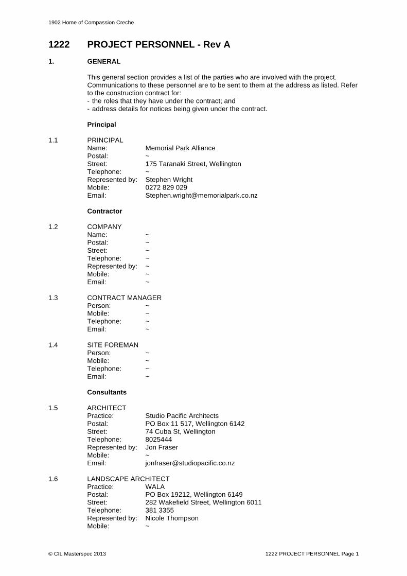
1902 Home of Compassion Creche
© CIL Masterspec 2013 1222 PROJECT PERSONNEL Page 1
1222 PROJECT PERSONNEL - Rev A 1. GENERAL This general section provides a list of the parties who are involved with the project.
Communications to these personnel are to be sent to them at the address as listed. Refer to the construction contract for:
- the roles that they have under the contract; and - address details for notices being given under the contract. Principal 1.1 PRINCIPAL Name: Memorial Park Alliance Postal: ~ Street: 175 Taranaki Street, Wellington Telephone: ~ Represented by: Stephen Wright Mobile: 0272 829 029 Email: [email protected] Contractor 1.2 COMPANY Name: ~ Postal: ~ Street: ~ Telephone: ~ Represented by: ~ Mobile: ~ Email: ~ 1.3 CONTRACT MANAGER Person: ~ Mobile: ~ Telephone: ~ Email: ~ 1.4 SITE FOREMAN Person: ~ Mobile: ~ Telephone: ~ Email: ~ Consultants 1.5 ARCHITECT Practice: Studio Pacific Architects Postal: PO Box 11 517, Wellington 6142 Street: 74 Cuba St, Wellington Telephone: 8025444 Represented by: Jon Fraser Mobile: ~ Email: [email protected] 1.6 LANDSCAPE ARCHITECT Practice: WALA Postal: PO Box 19212, Wellington 6149 Street: 282 Wakefield Street, Wellington 6011 Telephone: 381 3355 Represented by: Nicole Thompson Mobile: ~

1902 Home of Compassion Creche
© CIL Masterspec 2013 1222 PROJECT PERSONNEL Page 2
E-mail: ~ 1.7 STRUCTURAL ENGINEER Practice: Dunning Thornton Consultants Postal: PO Box 27153, Wellington 6141 Street: 94 Dixon Street, Wellington 6141 Telephone: 385 0019 Represented by: Adam Thornton Mobile: ~ Email: [email protected] 1.8 ELECTRICAL ENGINEER Practice: MPA 1.9 HYDRAULIC ENGINEER Practice: MPA 1.10 CIVIL ENGINEER Practice: MPA Territorial Authority 1.11 BUILDING CONSENT AUTHORITY Name: Wellington City Council Postal: ~ Street: ~ Telephone: ~ Mobile: ~ Email: ~

1902 Home of Compassion Creche
© CIL Masterspec 2013 1222L PROJECT PERSONNEL - LBP'S Page 1
1222L PROJECT PERSONNEL - LBP'S – Rev A 1. TO BCA: Wellington City Counsel Address: PO Box 2199
Wellington 6140 Copy to Contractor administrator Name: Stephen Wright Company/address: Memorial Park Alliance Email: [email protected] Project details Project: Home of Compassion Creche Siesmic Strengthening and Relocation Location: Buckle Street, Wellington Building Consent: Person giving advice Name: ~ Position: Contractor Telephone: ~ Date advised: ~ 2. GENERAL Provide to the Building Consent Authority the names of the Licensed Building
Practitioners who are carrying out Restricted Building Work on this project. In compliance with s87 of the Building Act, the names of LBP's who will be carrying out Restricted Building Work must be provided to the BCA before that work commences. Provide a copy to the Contract Administrator.
2.1 SITE Name: ~ LBP number: ~ Area of practice: Category ~ Details of RBW: ~ Address: ~ Telephone: ~ Mobile: ~ Email: ~ 2.2 CARPENTRY Name: ~ LBP number: ~ Area of practice: Category ~ Details of RBW: ~ Address: ~ Telephone: ~ Mobile: ~ Email: ~ 2.3 INTERNAL AND EXTERNAL SOLID PLASTERING (not modified plastering) Name: ~ LBP number: ~ Area of practice: Category Details of RBW: ~ Address: ~ Telephone: ~ Mobile: ~

1902 Home of Compassion Creche
© CIL Masterspec 2013 1222L PROJECT PERSONNEL - LBP'S Page 2
Email: ~ 2.4 ROOFING Name: ~ LBP number: ~ Area of practice: Category ~ Details of RBW: ~ Address: ~ Telephone: ~ Mobile: ~ Email: ~

1902 Home of Compassion Creche
© CIL Masterspec 2013 MAR 1231 CONTRACT Page 1
1231 CONTRACT – Rev A 1. GENERAL This GENERAL section refers to contract related matters. 1.1 NOMINATED SUBCONTRACTORS The contractor must appoint the following to carry out specific parts of the work. Arnold Murphy Plastering – all plastering. A&D Decorators – paint stripping (assuming that they do the sample areas for Equus).

1902 Home of Compassion Creche
© CIL Masterspec 2013 1232 INTERPRETATION & DEFINITIONS Page 1
1232 INTERPRETATION & DEFINITIONS – Rev A 1. GENERAL This general section relates to interpretation and definitions that are used in this
specification. 1.1 DEFINITIONS Required: Required by the documents, the New Zealand Building Code or by a
statutory authority. Proprietary: Identifiable by naming the manufacturer, supplier, installer, trade
name, brand name, catalogue or reference number. Provide and fix: "Provide" or "fix" or "supply" or "fix" if used separately mean provide
and fix unless explicitly stated otherwise. Review: Review by the contract administrator is for general compliance only.
Review does not remove the need for the contractor to comply with the stated requirements, details and specifications of the manufacturers and suppliers of individual components, materials and finishes. Neither can the review be construed as authorising departures from the contract documents.
Working Day: Working Day means a calendar day other than any Saturday, Sunday, public holiday or any day falling within the period from 24 December to 5 January, both days inclusive, irrespective of the days on which work is actually carried out.
1.2 PERSONNEL Owner: The person defined as "owner" in the New Zealand Building Code. Principal: The person defined as "principal" in the conditions of contract. Contractor: The person contracted by the principal to carry out the contract. Contract Administrator: The person appointed by the principal to administer the contract on
the principal's behalf. Where no person has been appointed by the Principal, it means the Principal or the Principal's representative.
1.3 ABBREVIATIONS The following abbreviations are used throughout the specification: AAMA American Architectural Manufacturers Association AS Australian Standard AS/NZS Joint Australian/New Zealand Standard ASTM American Society for Testing and Materials AWCINZ Association of Wall and Ceiling Industries of New Zealand Inc BCA Building Consent Authority BRANZ Building Research Association of New Zealand BS British Standard CSIRO Commonwealth Scientific and Industrial Research Organisation HERA Heavy Engineering Research Association LBP Licensed Building Practitioner MoBIE Ministry of Business, Innovation and Employment (includes the old
DBH) MPNZA Master Painters New Zealand Association Inc NZBC New Zealand Building Code NZS New Zealand Standard NZS/AS Joint New Zealand/Australian Standard NZTA New Zealand Transport Agency (previously TNZ) NUO Network Utility Operator PS1 Producer Statement – Design PS2 Producer Statement – Design Review PS3 Producer Statement - Construction PS4 Producer Statement – Construction Review RBW Restricted Building Work SARNZ Scaffolding and Rigging Association New Zealand Inc SED Specific Engineering Design

1902 Home of Compassion Creche
© CIL Masterspec 2013 1232 INTERPRETATION & DEFINITIONS Page 2
TA Territorial Authority TNZ Transit New Zealand (Transit New Zealand is now New Zealand
Transport Agency NZTA, some specifications are still prefixed TNZ) 1.4 DEFINED WORDS Words defined in the conditions of contract, New Zealand Standards, or other reference
documents, to have the same interpretation and meaning when used in their lower case, title case or upper case form in the specification text.
1.5 WORDS IMPORTING PLURAL AND SINGULAR Where the context requires, words importing singular only, also include plural and vice
versa.

1902 Home of Compassion Creche
© CIL Masterspec 2013 FEB 1233 REFERENCED DOCUMENTS Page 1
1233 REFERENCED DOCUMENTS – Rev A 1. GENERAL 1.1 REFERENCED DOCUMENTS Throughout this specification, reference is made to various New Zealand Building Code
Compliance Documents (NZBC __), acceptable solutions (__ AS_) and verification methods (__ VM_) for criteria and/or methods used to establish compliance with the New Zealand Building Code.
Reference is also made to various standards produced by Standards New Zealand (NZS,
AS/NZS, NZS/AS), overseas standards and to listed Acts, Regulations and various industry codes of practice and practice guides. The latest edition (including amendments and provisional editions) at the date of this specification applies unless stated otherwise.
It is the responsibility of the contractor to be familiar with the materials and expert in the
techniques quoted in these publications. Documents cited both directly and within other cited publications are deemed to form part
of this specification. However, this specification takes precedence in the event of it being at variance with the cited documents.
1.2 DOCUMENTS Documents referred to in the GENERAL sections are: NZBC F4/AS1 Safety from falling NZBC F5/AS1 Construction and demolition hazards AS/NZS 1170.2 Structural design actions - Wind loads AS/NZS 3012 Electrical installations - Construction and demolition sites NZS 3109 Concrete construction NZS 3114 Specification for concrete surface finishes NZS 3404:1997 Steel structures standard NZS 3602 Timber and wood-based products for use in building NZS 3604 Timber-framed buildings NZS 4210 Masonry construction: Materials and workmanship NZS 6803 Acoustics - Construction Noise National War Memorial Park (Pukeahu) Empowering Act 2012 Building Act 2004 Building Regulations 1992 Health and Safety in Employment Act 1992 Health and Safety in Employment Regulations 1995 New Zealand Building Code Historic Places Act 1993 Resource Management Act 1991 Smoke-free Environments Act 1990 OSH Guidelines for the provision of facilities and general safety in the
construction industry SARNZ Best practice guideline for scaffolding in New Zealand

1902 Home of Compassion Creche
© CIL Masterspec 2013 JUL 1234 DOCUMENTATION Page 1
1234 DOCUMENTATION – Rev A 1. GENERAL This general section relates to documentation required by the Territorial Authority/Building
Consent Authority for compliance with the New Zealand Building Code. It also includes documentation relating to:
- Substitutions - Manufacturers documents Building Consent Authority documentation 1.1 BUILDING CONSENT Obtain the original or copies of the building consent forms and documents from the owner
and keep them on site. Liaise with the BCA for all notices to be given and all inspections required during construction to ensure compliance. Return the consent form and documents to the owner on completion.
1.2 BUILDING CONSENT COMPLIANCE It is an offence under the Building Act 2004 - to carry out any work not in accordance with the building consent. - to carry out Restricted Building Work by anyone other than a Licensed Building
Practitioner licensed for that type of work. The resolution of matters concerning building code compliance to be referred to the
contract administrator for a direction in writing and then to the BCA for consent. Where any alteration is requested by the territorial authority or any other authority, do not
undertake such alteration until the matter has been referred to the Contract administrator for direction.
1.3 PROJECT PERSONNEL Provide names and contact detail of the contractor's key personnel and tradespersons
who are involved with the project. Provide the names in the form required in the general section of the specification. Review the list once a month and reissue it if changes have been made.
Licensed Building Practitioner documentation 1.4 LICENSED BUILDING PRACTITIONERS On behalf of the Owner, provide details of LBP's to carry out or supervise Restricted
Building Work. Provide names, LBP numbers, areas of practice and other required information. Provide this to the BCA and the Contract Administrator before commencing work on the Restricted Building Work. Provide the information in the form required in the general section 1222L PROJECT PERSONNEL LBP'S. Review the list once a month and reissue it if changes have been made.
Include the following which are considered applicable to this project: - Site LBP - Carpenter - Foundations 1 Concrete foundation walls and concrete slab-on-ground constructor - Roofing 2 Profiled metal roofer and/or wall cladding installer - Roofing 4 Membrane roofer - Roofing 5 Torch on membrane roofer - External plastering 1 Solid plasterer - External plastering 2 Proprietary Plaster Cladding Systems (PPCS) plasterer Also provide names and contact details of the following - Registered drainlayer - Registered plumber - Registered electrician

1902 Home of Compassion Creche
© CIL Masterspec 2013 JUL 1234 DOCUMENTATION Page 2
1.5 NOTIFICATION OF BREACHES OF BUILDING CONSENT Provide to the Contract Administrator and the Contractor a copy of any advice given to
the BCA under s.89 of the Building Act. Provide this advice no later than the time the advice is given to the BCA.
1.6 RECORD OF BUILDING WORK Where Restricted Building Work is carried out by a LBP, on completion of the RBW
provide a Record of Building Work for inclusion with the documentation required for Code Compliance. Provide copies to both the BCA and the Contract Administrator.
Compliance information 1.7 DOCUMENTATION REQUIRED FOR CODE COMPLIANCE Information may be required either as a condition of the contract documents or as a
condition of the building consent may include the following: - - Applicators approval certificate from the manufacturer / importer / distributor - Manufacturer's, importer's or distributors warranty - Installer / applicator's warranty - LBP Record of Work - Producer Statement - Construction from the applicator / installer Producer Statement - Construction review from an acceptable suitably qualified person Refer to the general sections for the requirements for compliance information to be
provided by the contractor. Refer to the National War Memorial Park (Pukeahu) Empowering Act 2012 for the
requirements for compliance information to be provided by the contractor. Obtain required documents from the relevant parties for delivery to the contract
administrator after the final inspection has been carried out by the Building Consent Authority.
Substitutions 1.8 ACCEPTABLE PRODUCT/MATERIAL SUPPLIERS Where a product or material supplier is named in SELECTIONS, the product/material
must be provided by the named supplier. Where more than one named supplier, any one of the named suppliers will be acceptable.
1.9 NO SUBSTITUTIONS Where specifically stated in a section, substitutions are not permitted to any of the
specified systems, components and associated products listed in that section. 1.10 PROPOSED SUBSTITUTIONS A substitution may be proposed where specified products are not reasonably available. A
substitution may also be proposed by the Contractor where the Contractor considers a proposed substitution to be an alternative to the specified product. Except where a specified product is not available, the Contract administrator is not bound to accept any substitutions. Where branded work sections are included in this specification, substitution of those products or systems will not be allowed.
1.11 NOTIFICATION OF SUBSTITUTIONS Notify proposed substitution of specified products. Notification to include but not be
limited to: - Product identification - Manufacturer's name, address, telephone and facsimile numbers, website and email
address - Detailed comparison between the properties and characteristics of the specified product
and the proposed substitution - Statement of NZBC compliance including durability - Details of manufacturer warranties

1902 Home of Compassion Creche
© CIL Masterspec 2013 JUL 1234 DOCUMENTATION Page 3
plus an assessment of - Any changes required to the programme including any extension of time required - Any consequential effects of the proposed substitution - Allowance for time and cost for re-design and documentation (if applicable) - Allowance for time and cost for obtaining an amendment to the Building Consent (if
applicable) - Any change in cost associated with the proposed substitution and if requested - All current manufacturer's literature on the product - Accreditations and appraisals available - Reference standards - Product limitations - Samples - List of existing installations in the vicinity of the project 1.12 ACCEPTANCE OF SUBSTITUTIONS The Contract administrator must advise of acceptance of substitutions in writing. Amendment to issued Building Consent 1.13 CONTRACTOR AMENDMENTS TO BUILDING CONSENT Where the contactor has sought acceptance of a substitution or a variation which is for
the contractor's own convenience and the substitution or variation requires an amendment to the Building Consent, the contractor must apply for and obtain the required amendment.
The contractor must: - Obtain approval for substitutions from the Contract administrator. - Prepare and provide to the BCA all documentation required for the amendment. - Pay all fees and other costs associated with this amendment. - Where the amendment affects other approved plans, also amend those plans. 1.14 PRINCIPALS AMENDMENTS TO BUILDING CONSENT Where the principal is proposing a substitution or a variation which requires an
amendment to the Building Consent, the contractor must provide to the principal information that the contractor has that is required for the amendment.
The principal will: - Prepare and provide to the BCA all documentation required for the amendment. - Pay all fees and other costs associated with this amendment. - Where the amendment affects other approved plans, also amend those plans. Manufacturer's documents 1.15 BRANDED WORK SECTIONS Branded sections may be included in this specification relating to specific products and
systems to be installed as part of the contract works. Where branded sections are included, substitutions to the branded products and systems will not be allowed.
1.16 CROSS REFERENCED WORK SECTIONS If any related work is cross referenced to a generic work section, but only the equivalent
branded section is included in the specification, use that branded section. Confirm with the Contract administrator if there is any doubt.
1.17 MANUFACTURER'S AND SUPPLIER'S REQUIREMENTS Manufacturers and supplier's requirements, instructions, specifications or details mean
those issued by them for their particular material, product or component and are the latest edition.
1.18 MANUFACTURER'S AND SUPPLIER'S DOCUMENTS Refer to individual sections for a detailed list of manufacturer's and supplier's documents
relating to work on this project. Retain current copies of the documents listed, and all

1902 Home of Compassion Creche
© CIL Masterspec 2013 JUL 1234 DOCUMENTATION Page 4
other relevant manufacturer's technical literature, on site. Make this information available to all personnel and ensure they are familiar with requirements for handling, storing, preparing for, fixing and finishing all products before commencing work. Provide a copy of all listed manufacturer's literature to the Contract administrator.
1.19 ONGOING MAINTENANCE REQUIREMENTS Refer to individual sections for details of manufacturer's and supplier's requirements for
ongoing maintenance necessary to ensure continuing compliance with the durability requirements of the NZBC. Provide a copy of literature detailing ongoing maintenance and inspection requirements to the Contract administrator.
Shop drawings 1.20 PROVIDE SHOP DRAWINGS FOR REVIEW Where specified in the work sections provide shop drawings for review by the contract
administrator. Allow in the program for the shop drawing and review process. Do not proceed with manufacture of the items until the Contract administrator gives a direction to proceed.

1902 Home of Compassion Creche
© CIL Masterspec 2013 JUN 1235 SHOP DRAWINGS Page 1
1235 SHOP DRAWINGS - Rev A 1. GENERAL This general section relates to common requirements for the preparation, submission and
review of shop drawings. Detailed requirements for shop drawings for particular parts of the work are included in the specific work section.
1.1 PREPARE SHOP DRAWINGS Where specified in the work sections prepare shop drawings and submit for review.
Make due allowance in the contract programme for the preparation, review and subsequent correction and re-review of shop drawings, prior to the time required for ordering materials/equipment and commencing fabrication.
1.2 SHOP DRAWINGS REVIEW Submit shop drawings to the named reviewer(s) for review. Proposed shop drawings to
be submitted to the reviewer, in due time to ensure conformance with the contract programme.
- Where no time is stated in a specific section allow 10 working days for review by the reviewer. Where a large number of drawings are involved more time will be necessary.
- Where no person is named in a specific section as the reviewer, submit the shop drawings to the contract administrator.
Shop drawing review indicates only that the supplied interpretation of the design concept
has been reviewed without the need for further modification, other than the corrections indicated by the reviewer.
Review of shop drawings does not relieve the contractor of responsibility for the
correctness of the shop drawings, site dimensions, the overall design and performance, or for ensuring the work is carried out in compliance with the contract documents. Nor does it remove the need for the contractor to comply with the stated requirements, details and specifications of the manufacturer's and suppliers of individual components, materials and finishes. Neither can the review be construed as authorising departures from the contract documents.
Reviewed drawings which contain comments or notations indicating where the shop
drawings are at variance with the contract documents to be modified and resubmitted to the reviewer for re-review. Allow 5 working days for re-review by the reviewer.
1.3 PROVIDE FINAL SHOP DRAWINGS Provide final shop drawings, including required modifications, before proceeding with any
fabrication, installation or erection. 1.4 SHOP DRAWING REVIEWER(S) Submit the following shop drawings for review to the named reviewer(s) identified in this
clause or the specific work section, if no reviewer(s) are identified submit to the contract administrator:
Item Reviewer(s) Timber windows & doors Studio Pacific Architecture 1.5 SCHEDULE OF SHOP DRAWINGS The following work sections have shop drawing requirements, refer to these sections for
details: 4511 Timber windows and doors

1902 Home of Compassion Creche
© CIL Masterspec 2013 1237 WARRANTIES Page 1
1237 WARRANTIES – Rev A 1. GENERAL This general section refers to the requirements for warranties as listed, either in this work
section and/or in specific work sections. It includes: - - Warranties for parts of the work required by the Principal in a required form - Installer/applicator warranties for parts of the work in the installer/applicator's standard
form - Manufacturer/supplier warranties provided with products, appliances and the like in the
suppliers standard form - Guarantees/Warranties provided by contractors in the contractor's standard form Warranties 1.1 PROVIDE WARRANTIES Provide executed warranties in favour of the principal in respect of, but not limited to,
materials, components, service, application, installation and finishing called for in that specified section of work. The terms and conditions of the warranty in no case negate the minimum remedies available under common law as if no warranty had been offered. Failure to provide the warranty does not reduce liability under the terms of the warranty called for in that specified section of work.
- Conform to the 1237WA WARRANTY AGREEMENT form included in the
specification/conditions of contract. - Commence warranties from the date of practical completion of the contract works
(unless otherwise stated). - Maintain their effectiveness for the times stated. - Provide executed warranties prior to practical completion. 1.2 WEATHERTIGHTNESS AND WATERTIGHTNESS WARRANTY A warranty is required from the contractor for a minimum period of 2 years, covering the
weathertightness of the complete building envelope and the watertightness of all liquid supply and disposal systems and fittings. This general warranty is in addition to any specific warranties required.
Provide this warranty in favour of the principal. The terms and conditions of this warranty
in no case negate the minimum remedies available under common law as if no warranty had been offered. Failure to provide the warranty does not reduce liability for execution and materials for that part of the work.
- Conform to the standard form1237WA WARRANTY AGREEMENT included in the
contract documents. - Commence the warranty from the date of Practical Completion. - Maintain its effectiveness for the time stated. 1.3 WARRANTIES - INSTALLER/APPLICATOR Where installer/applicator warranties are offered covering execution and materials of
proprietary products or complete installations, provide such warranties to the contract administrator. These warranties may be provided in lieu of the warranties that are otherwise required provided that these warranties are subject to similar conditions and periods.
Provide warranties in favour of the principal. The terms and conditions of such warranties
in no case negate the minimum remedies available under common law as if no warranty had been offered. Failure to provide the warranty does not reduce liability for execution and materials for that part of the work.
- Conform to the installer/applicator standard form. Where the installer/applicator does
not have a standard form, use the 1237WA WARRANTY AGREEMENT included in the contract documents.
- Commence the warranties from the date normally applicable for the work.
1902 Home of Compassion Creche
© CIL Masterspec 2013 1237 WARRANTIES Page 2
- Maintain their effectiveness for the times stated. 1.4 WARRANTIES - MANUFACTURER/SUPPLIER Where warranties are offered covering materials, equipment, appliances or proprietary
products, provide all such warranties to the contract administrator. Provide warranties in favour of the principal. The terms and conditions of such warranties
in no case negate the minimum remedies available under common law as if no warranty had been offered. Failure to provide the warranty does not reduce liability for execution and materials for that part of the work.
- Conform to the manufacturer/suppliers standard form. - Commence the warranties from the date normally applicable. - Maintain their effectiveness for the times stated. Submissions 1.5 REVIEW BY CONTRACTOR Obtain the warranties from the installers and suppliers at the earliest possible date and
review to ensure that they are correctly filled out and executed. Where warranties are executed as a deed, ensure that a duplicate copy is provided for execution by the Principal/Owner. Keep safe and secure until required for submission.
1.6 WARRANTIES - REQUIRED BY CONTRACT Obtain copies of warranties listed in the contract documents for submission to the
Contract Administrator/Owner. Provide all warranties at the same time. Present the warranties to the Contract Administrator in a "clear view" document book suitably labelled with the project name and details. If the project has an operations and maintenance documentation provision, present the warranties with the operations and maintenance information.
1.7 TIME FOR SUBMISSION Refer to the contract conditions for any requirement relating to the time for submission for
warranties
NZS 3910 Contracts Submit all warranties before the end of the defects liability period.
Warranties schedule 1.8 SCHEDULE OF WARRANTIES Provide the Warranties and Guarantees listed in this section: 2 years Weathertightness and watertightness 5 years Profiled metal roofing 5 years Torch-on membrane roofing 1 year Timber strip, block & plank flooring 2 years Painting Additionally the following work sections have Warranty requirements, refer to these
sections for details: ~

1902 Home of Compassion Creche
© CIL Masterspec 2013 1237WA WARRANTY AGREEMENT Page 1
1237WA WARRANTY AGREEMENT – Rev A 1. WARRANTY AGREEMENT Contract for: Home of Compassion Creche Strengthening and Relocation (the contract works) Contractor: ~ (the contractor) Principal: Memorial Park Alliance (the principal) Warrantor: (name of contractor, subcontractor or materials supplier) Warranted works: (the warranted works) Warranted materials: (the warranted materials) Warranty period: years from the date of practical completion of the contract
works. The principal has entered into a contract (the contract) with the contractor for carrying out
the contract works. The warranted works / materials are part of the contract works. The contractor has agreed to arrange for the provision of a warranty in respect of the
warranted works / materials for the warranty period on the terms set out in this warranty. The warrantor has agreed to provide a warranty in respect of the warranted works /
materials for the warranty period on the terms set out in this warranty. 2. IT IS HEREBY AGREED The warrantor warrants to the principal that the warranted work performed /materials
supplied shall be as required in the contract. If not specified the work shall be of good trade practice with materials and fittings of merchantable quality.
This warranty shall be in addition to and shall not derogate from any manufacturer's
warranty or any warranty implied by law, attaching to any part of the warranted works. 2.1 WARRANTOR'S OBLIGATIONS The warrantor agrees that if the warrantor is advised by the principal in writing of any
defect in the warranted works / materials within the warranty period for which the warrantor is liable under the terms of this warranty, the warrantor will promptly take steps to remedy the defect / replace defective materials.
2.2 REMEDIAL WORK / REPLACEMENT OF DEFECTIVE MATERIALS Any remedial work / replacement of defective materials which the warrantor is liable to
undertake / provide under this warranty shall be carried out: - to the standard required by the contract; and - in a prompt and timely manner; and - without unnecessary inconvenience to any occupants; and - at the warrantor's cost; and - subject to reasonable access being provided to the warrantor for the purpose of carrying
out the remedial work. 2.3 REPAIR, REPLACEMENT AND/OR COMPENSATION Where the cost of replacement of work and/or materials is out of all proportion to the
consequences of the defect, or where the defect may not be reasonably capable of
1902 Home of Compassion Creche
© CIL Masterspec 2013 1237WA WARRANTY AGREEMENT Page 2
rectification without substantial expense which is out of all proportion to the cost of the contract works, the warrantor may:
- where the defect or defective material is reasonably rectified by repair rather than by replacement, the warrantor's obligation under this warranty shall be only to repair or otherwise make good the defect or
- propose reasonable monetary compensation in lieu of remedying the defect or - propose a combination of both repair and compensation. The principal must consider the warrantor's reasonable proposals and the parties must
endeavour in good faith to reach agreement. Where agreement cannot be reached the dispute shall be resolved in accordance with the disputes clause in this warranty.
2.4 FAILURE BY WARRANTOR TO PERFORM REMEDIAL WORK If the warrantor fails to promptly, adequately and satisfactorily carry out the remedial work
or to propose acceptable repair/compensation, the principal may then arrange for the remedial work to be carried out by others.
If the warrantor fails to promptly, adequately and satisfactorily provide replacement
materials or to propose acceptable repair/compensation, the principal may then arrange for the replacement materials to be supplied by others.
The principal must first give the warrantor 10 working days notice to carry out and
complete the remedial work / supply replacement materials. If the warrantor does not complete this work / supply replacement materials within the time, the principal must then advise the warrantor in writing that the work will be carried out / materials will be supplied by others.
In such event the warrantor is not released from obligations under this warranty, which
continues in full force and effect, except in respect of the defect remedied / materials supplied by the principal or by another person contracted by the principal. The reasonable cost of the remedial work carried out / materials supplied by such other persons including all reasonable costs of the principal is to be paid to the principal by the warrantor on demand.
2.5 EXCLUSIONS The principal agrees that the warrantor is not liable for any defect or damage caused by: - wilful act or negligence of the principal or any person other than the warrantor; or - fire, explosion, earthquake, war, subsidence, slips, faulty materials or workmanship
other than caused by the defect in the warranted work; or - any force of nature which the warrantor could not reasonably foresee; or - any neglect or unnecessary delay by the principal in giving notice to the warrantor of a
defect in the warranted works becoming apparent; or - design faults, errors or discrepancies, unless the warrantor undertook the design of the
part of the warranted works the subject of the defect; or - unintended use of the warranted works by the principal or any occupant thereof; or - failure by the principal or any occupant thereof to maintain the warranted works in
accordance with good practice and any manufacturer's stated or recommended instructions or requirements.
2.6 ASSIGNMENT The principal may assign the benefit of this warranty to any person. 2.7 DISPUTES Any dispute or difference between the principal and the warrantor arising out of or in
connection with this warranty, or the subject matter of this warranty, including any question about its existence or validity, will be referred to arbitration by a sole arbitrator to be agreed upon by the parties. If the parties are unable to agree upon the identity of an arbitrator within 10 working days from the date upon which notice of the dispute is given, then the arbitrator will be appointed by the Registrar of the Building Disputes Tribunal (NZ) Ltd upon the application of either party.
2.8 NOTICES Notices given to the warrantor are deemed to have been effectively served on the

1902 Home of Compassion Creche
© CIL Masterspec 2013 1237WA WARRANTY AGREEMENT Page 3
warrantor if given in accordance with the contract. 3. EXECUTED BY
Signed by the warrantor: ………………………………………..……………………... on this: …………….day of ……………………………..…20…… (day) (month) (year)
(And where required to be executed as a deed) signed in the presence of:
Witness signature ……………………………………………………………... Name: ……………………………………………………………... (print) Address: ……………………………………………………………... (print) Occupation: ……………………………………………………………... (print) Signed by the principal: ……………………………………………………………... on this: …………….day of ……………………………..…20…… (day) (month) (year)
(And where required to be executed as a deed) signed in the presence of:
Witness signature ……………………………………………………………... Name: ……………………………………………………………... (print) Address: ……………………………………………………………... (print) Occupation: ……………………………………………………………... (print)
NOTE - Where the warrantor is not the contractor the warranty agreement must be
executed by the warrantor and the principal in the manner required for execution of a deed.
Any of these parties which are a company must execute the warranty by having it signed,
under the name of the company, by two or more directors. If there is only one director, it is sufficient if the warranty agreement is signed under the name of the company by that director, but the signature must be witnessed by another person. The witness must not only sign but must also add his or her occupation and address. Alternatively, companies may execute under power of attorney. Any party which is a body corporate (other than a company) must execute by affixing its seal, which must be attested in the manner provided for in the rules of, or applicable to, the body corporate.
In the case of a party who is an individual, the party must sign and the signature must be
witnessed by another person. The witness must not only sign but must also add his or her occupation and address.

1902 Home of Compassion Creche
© CIL Masterspec 2013 1240 ESTABLISHMENT Page 1
1240 ESTABLISHMENT - Rev A 1. GENERAL This general section relates to site establishment including: - Notices and approvals - Inspections - Site preparation - Signage - Temporary construction Notices and approvals 1.1 STATUTORY OBLIGATIONS Comply with all statutory obligations and regulations of regulatory bodies controlling the
execution of the works. 1.2 BUILDING CONSENT AUTHORITY AND NETWORK UTILITY APPROVALS Attend on Building Consent Authority officers, statutory and network utility inspectors, as
necessary to obtain approvals (in addition to building consent approval) for and the satisfactory completion of, the works.
1.3 NOTIFY NETWORK UTILITY OPERATORS Notify all network utility operators of proposed works before commencing site operations.
Ascertain location of services or confirm that none exist in the vicinity of the works. Take all necessary precautions to avoid damage to existing services.
Inspections 1.4 CARRY OUT INSPECTIONS The contractor is to undertake a full inspection of the existing building, interior and
exterior conditions along any work undertaken by previous contractors. Any areas of concern are to be raised with the clients representative before any work proceeds.
Site preparation 1.5 SITE ACCESS Access to the site is limited to: MPA to advise 1.6 WORKING AREA Limited to the following designated working areas on the site:
MPA to advise Existing buildings 1.7 ALTERATIONS Control access and working areas within the existing building. Signage 1.8 SITE SIGN Obtain approval for, provide and erect a timber framed sign board 2400mm x 1200mm
fully painted and displaying: - Title of contract - Principal's name - Contractor's name - Consultants as listed in general section 1222 PROJECT PERSONNEL - If the contractor wishes, names of contractor and subcontractors. Temporary construction

1902 Home of Compassion Creche
© CIL Masterspec 2013 1240 ESTABLISHMENT Page 2
1.9 HOARDINGS, GANTRIES, LIGHTING Provide temporary fencing, hoardings, planked footways, guard rails, gantries and lighting
as necessary to protect the public and others, for the proper execution of the works and to meet the requirements of territorial or other authority.

1902 Home of Compassion Creche
© CIL Masterspec 2013 FEB 1250 TEMPORARY WORKS & SERVICES Page 1
1250 TEMPORARY WORKS & SERVICES – Rev A 1. GENERAL This general section relates to temporary works and services required for the construction
of the contract works. It includes: - Temporary works and services including temporary fencing and hoardings - Scaffolding and shoring - General care and protection Temporary works 1.1 COMPLY WITH NEW ZEALAND BUILDING CODE Refer to New Zealand Building Code clauses and approved document paragraphs for the
criteria and/or methods that must be used in this section to establish compliance with the code.
1.2 COSTS RELATING TO TEMPORARY WORKS Pay all rates/fees in respect of temporary works. 1.3 MAINTENANCE OF TEMPORARY WORKS Maintain alter, adapt and move temporary works and services as necessary. Clear away
when no longer required and make good. 1.4 SAFEGUARD THE SITE, THE WORKS AND MATERIALS Take all precautions to prevent unauthorised access, including access outside working
hours, to the site, the works and adjoining property. Safeguard the site, the works, materials and plant from damage and theft. Co-ordinate with MPA security.
1.5 SITE FENCING Provide and maintain a site fence, 2 metres high from ground level on the side accessible
to the public. Construct to comply with NZBC F5/AS1 Construction and demolition hazards. Construct as required for public areas and as shown on the drawings.
Construct the fence with: - galvanized chain link netting with a 50mm x 50mm maximum grid size - posts at 2.5 metre centres maximum - gap at the bottom of the fence no greater than 100mm 1.7 SITE FENCING - NON PUBLIC AREAS Provide and maintain a 1 metre high site fence to non public areas. Construct using: - warratah stakes at 1.5 metre centres fitted with safety caps - plastic safety mesh 1.8 PROVIDE SEDIMENT AND SILT RUN OFF PROTECTION Provide appropriate measures to prevent or minimise sediment generation and silt run off.
Comply with territorial and other authority requirements relating to carrying out earthworks.
Prevent silt run off by: - exposing only as much ground as required at any time - providing run off channels, contour drains or earth bunds to divert clean water away
from the site on to stable sealed or grassed ground - capture silt by the use of silt fences, vegetation buffer strips, sediment ponds or earth
bunds. Provide sediment control by: - earth bunds constructed across the slope to control and detain run off - silt fences constructed using filter fabric stretched between posts at a maximum of 1
metre spacing. Pump water from trenches and other areas of the site using methods to prevent sediment
entering any drain or watercourse. Filter dirty water before discharging into drainage

1902 Home of Compassion Creche
© CIL Masterspec 2013 FEB 1250 TEMPORARY WORKS & SERVICES Page 2
system. 1.9 PROVIDE CONCRETE WASHWATER RUN OFF PROTECTION Provide appropriate measures to prevent cement/concrete washwater or slurry run off to;
drains or waterways, landscaped areas new or remaining and adjoining public or private properties. Comply with territorial and other authority requirements relating to cement/concrete washwater.
Control run off from: - Cement/concrete based material production, placing and finishing. - Hosing down and cleaning of, tools and equipment, fresh material, and spilt or surplus
material, pumps and mixers etc. - Wet cutting or grinding. - Slab watering etc. - Water cleaning of new concrete elements, fresh used formwork etc. Large project and those without suitable ground area - prevent run off by: - plan and implement washwater control measures based on the expected volumes, allow
for the timely removal and safe disposal of liquids and solids. - control the volumes of water used for washing down, the more water used the bigger
the problem. - Control the flow of washwater so that it is directed to proper catchments. - providing watertight bunds, pits or tanks, filtered washwater is not to be discharged to
drains. Spilt or surplus material: - if possible allow to set and either use or dispose of as hardfill. - pre-made concrete items, either use or dispose of as hardfill. Pump washwater away from drains, waterways and adjoining property. Temporary services 1.10 WATER Provide clean, fresh water for the works and make arrangements for distributing about the
site. 1.11 ELECTRICITY To AS/NZS 3012. Nominate the person to install and be responsible for the complete temporary electrical
installation. The name and designation of the person responsible is to be displayed prominently and close to the main switch or circuit breaker.
Inspect and overhaul the installation at such intervals as are prescribed by the network
utility operator but not exceeding three monthly intervals. 1.12 TELEPHONE Provide on site temporary telephone facilities. 1.13 COMPUTER Provide on-site temporary computer facilities complete with an email and internet
connection capable of sending, receiving and printing site communications. Scaffolding and shoring 1.14 GENERAL SCAFFOLDING Provide as necessary general scaffolding for the efficient execution of the works.
Placement, erection and structure to be by certified suppliers/erectors and approved by the Labour Department OSH inspectors before being used. Comply with the SARNZ publication: "Best practice guidelines for scaffolding in New Zealand."
Care and protection

1902 Home of Compassion Creche
© CIL Masterspec 2013 FEB 1250 TEMPORARY WORKS & SERVICES Page 3
1.15 PROTECT EXISTING SERVICES Protect existing services and parts of service systems that are to remain in place during
the execution of the works. Provide temporary caps or covers to prevent the ingress of dust and other contaminants into the systems, ducts, pipes etc.
1.16 MAKE GOOD EXISTING SERVICES Make good all damage to existing roads, footpaths, grounds, sewers or other services,
caused in carrying out the contract works. 1.17 CONSTRUCTION KEYING AND SECURITY Provide locksets with temporary keying, or install with the cylinders removed. 1.18 TEMPORARY STORAGE Provide temporary storage areas and protective covers and screens to approval of
architect. Refer to Schedule of Items for Removal and Storage, or Protection for details of storage and stacking requirements. Fillet stack and protect all framing and structural members from moisture and contamination. Completely protect finishing materials from the weather and damage and store in accordance with the manufacturer's requirements. Protect fabricated elements from the weather and damage, and store in accordance with suppliers' requirements.
1.19 SPECIAL PROTECTION Refer to Schedule of Items for Removal and Storage, or Protection for details of storage
and stacking requirements. 1.20 PERIODIC SITE CLEANING Carry out periodic site cleaning during the contract period. Place waste material in
appropriate storage pending removal from the site. 1.21 PERIODIC RUBBISH REMOVAL Maintain on site appropriate means for the storage and removal of construction waste
material. Where required or appropriate provide for the separate storage of recyclable waste and other materials requiring special disposal. Keep food waste separate from construction waste.

1902 Home of Compassion Creche
© CIL Masterspec 2013 1256 WASTE MANAGEMENT Page 1
1256 WASTE MANAGEMENT – Rev A 1. GENERAL This general section relates to the implementation of a site waste management plan. 1.1 DOCUMENTS REFERRED TO Documents referred to in this section are: REBRI Resource Guides Website: www.rebri.org.nz/ Documents listed above and cited in the clauses that follow are part of this specification.
However, this specification takes precedence in the event of it being at variance with the cited document.
1.2 ABBREVIATIONS The following abbreviations are used in this specification: REBRI Resource Efficiency in the Building and Related Industries Requirements 1.3 WASTE MANAGEMENT PLAN Prepare and submit a waste management plan in line with the guidelines provided in the
REBRI Guides. www.rebri.org.nz/ The submitted plan to include the following factors: - site planning and material storage - waste management - purchasing - recycling - salvage. 1.4 RECORD KEEPING Maintain a record of waste materials, recycled, reused and disposed of by the project
using the REBRI Waste Management Plan and REBRI C&D Waste Transfer Form or a form generated by the contractor containing the same information.
- For each material recycled from the project, include the amount (in cubic metres or tonnes), or in the case of reuse, state quantities by number, type and size of items, and the destination (i.e. recycling facility, used building materials yard).
- For each material land filled, include the amount (in cubic metres or tonnes) of material and the identity of the landfill, clean fill and/or transfer station.
If requested, submit to the Contract Administrator the REBRI Waste Management Plan,
REBRI C&D Waste Transfer Forms or bills, invoices and other documentation confirming that all materials have been received at the required locations.
1.5 ENSURE Ensure all site management and staff, subcontractors, material and product suppliers and
waste disposal companies are made aware that this is a REBRI project and provide access to or copies of the waste management plan.
Equipment 1.6 CONTAINERS Provide appropriately sized and sited containers for the storage of reusable, recyclable
and waste products. Clearly label each container. Conditions 1.7 STORAGE Store all materials so they are not damaged prior to use. 1.8 PLANNING Plan the measurement and ordering of materials and components to minimise waste.
1902 Home of Compassion Creche
© CIL Masterspec 2013 1256 WASTE MANAGEMENT Page 2
Application 1.9 DEMOLITION - Sort concrete and concrete block waste for recycling as aggregate, sub-base material or
fill. - Sort brick waste for reuse as whole bricks, or re-use as crushed brick for landscape
cover, sub-base material or fill. - Sort asphalt material by type for milling and recycling. 1.10 DISMANTLING/REUSE - Dismantle, store and protect items, elements and components for reuse on site. - Dismantle, store and protect items, elements and components for recycling off site. - Dismantle store and protect items, elements and components for return to the owner. 1.11 SITE CLEARING - Sort asphalt material by type for milling and recycling. - Grind, chip or shred vegetation for mulching and composting on site. - Grind, chip or shred vegetation for off site mulching and composting. - Separate and recycle steel reinforcing and other metals. - Provide suitable on-site locations for the disposal of excavated rock, soil and vegetation. 1.12 CONCRETE - Plan for maximum re-use of concrete formwork. - Separate and recycle concrete. - Provide a suitable on-site location for the disposal of excess concrete. 1.13 WOOD - Separate and recycle wood offcuts and waste. - Separate timber for reuse - Provide a suitable storage area for sizeable off-cuts for use as spacers or blocking. - Separate CCA treated timber from untreated timber. - Chip untreated timber for mulching and composting on site. - Chip untreated timber for off site mulching and composting. 1.14 PLUMBING - Select plumbing materials with a high recycled content. - Ensure that reusable packaging materials are returned to the vendors. - Retain PVC off-cuts for use as stubs. - Separate and recycle plastics. 1.15 ELECTRICAL - Select electrical materials with a high recycled content. - Ensure that reusable packaging materials are returned to the vendors. - Separate and recycle metals and wire. - Separate and recycle plastics. 1.16 MECHANICAL - Select mechanical materials with a high recycled content. - Ensure that reusable packaging materials are returned to the vendors. - Separate and recycle metals and wire. - Separate and recycle plastics. Completion 1.17 CLEANING All cleaning materials used on the project to be biodegradable and non-toxic.

1902 Home of Compassion Creche
© CIL Masterspec 2013 1260 PROJECT MANAGEMENT Page 1
1260 PROJECT MANAGEMENT – Rev A 1. GENERAL This general section relates to project management requirements including: - Meetings - Cost control - Communicating and recording - Programming - Health and safety Site Meetings 1.1 SITE MEETINGS Meetings to normally be held: Fortnightly The following persons to attend: - Principal - Contract administrator - Project manager - Contractor - Architect - Designer - Engineer - Services consultants when needed - Subcontractors when needed (contractor to inform them). Meeting place: TBC Time: TBC Day: TBC 1.2 SITE MEETING MINUTES The contract administrator is to keep full minutes of all site meetings and arrange
distribution to all those involved within 3 working days. The minutes are to record - Documentation and information issued and required - Directions and variations issued - Confirmation of contract insurances - Programme - General business - Site health and safety - Payment claim processing including costing variations Reporting 1.8 CONTRACTORS DETAILED STATUS REPORT Where required a Contractors detailed status report is to address the following: - A progress performance report based on the current contract construction programme
addressing actual progress against programme of all activities and any variance from the programme.
- Details of measures being taken to get work back on programme where there has been a delay.
- Details of any future events that will or are likely to affect compliance with the programme.
- Variation report including progress on agreed variations, variations to be agreed and anticipated variations and the time implication of variations.
- Procurement progress on parts of the work being undertaken under a monetary allowance including the time by which direction must be given on monetary allowances to conform with the construction programme.
- Details of any discrepancies in the contract documents that require clarification or determination.

1902 Home of Compassion Creche
© CIL Masterspec 2013 1260 PROJECT MANAGEMENT Page 2
- A list of information requests by the contractor, the date when they were made, the person who they were directed to and the date by which a response is required.
- A report on compliance with the issued Building Consent and any parts of the work that have not been passed by the BCA inspector.
- A report on compliance with the issued Resource Consent and any compliance issues. - A report of site health and safety including any notifiable incidents. 1.9 QUANTITY SURVEYORS DETAILED STATUS REPORT Where required a quantity surveyors detailed status report is to address the following: - A report on actual cash flow compared with planned cash flow - Variation costing and the adjusted contract price - Monetary allowance review of sums not yet directed for expenditure by the contractor - An assessment of the cost of known and potential variations - An updated project budget including known and projected costs plus an allowance for
contingent and unknown costs. 1.10 CONSULTANTS DETAILED STATUS REPORT Where required a consultants detailed status report is to address the following: - A report on construction quality compared to specification and other performance
requirements. - Identification of items or parts of the work where there are or may be quality compliance
issues with respect to the issued Building Consent - Identification of items or parts of the work where there are or may be quality compliance
issues with respect to the ability of the consultant to issue any required producer statement.
Communicating and recording 1.11 MEANS OF COMMUNICATION Communications between the parties shall be as follows: - Directions: In writing delivered by email with a copy by post or hand Meeting minutes: In writing delivered by email RFI's: (Requests for information) by email or in writing to the contract
administrator 1.12 DELIVERY OF COMMUNICATIONS Communications must be: - - delivered to the addressee by hand; or - posted to the postal address stated in the Project Directory; or - delivered to the street address as stated in the Project Directory; or - sent by email to the email address stated in the Project Directory; or The Principal, Contractor and the Contract administrator must notify the others if they
change their address for delivery or transmission of communications. 1.13 RECORDS Ensure all records specified are kept, held and collated on site in a form that makes the
information easily accessible when it is needed. Distribute copies as and when necessary to those persons entitled under the contract to that information.
1.14 PROGRESS PHOTOGRAPHS Take digital photographs from positions agreed with the contract administrator at
specified frequency and provide copies to the contract administrator. Refer to Location/Heritage Management Plan for details of recording required.
Health and safety 1.15 HEALTH AND SAFETY Refer to the requirements of the Health and Safety in Employment Act 1992. Comply
with all relevant New Zealand safety legislation.

1902 Home of Compassion Creche
© CIL Masterspec 2013 1260 PROJECT MANAGEMENT Page 3
Take all practical steps to make the site and the contract works safe and to provide and maintain a safe working environment. Ensure that all those working on or visiting the site are aware of the rules governing site safety, are properly supervised and are not unnecessarily exposed to hazards.
Identify any significant hazards. Maintain proper procedures for dealing with any emergencies that may arise.
Immediately investigate accidents, identify their cause and maintain a register of accidents and serious harm. Provide a copy of any report which the contractor is required to make to a public authority on any accident which is associated with carrying out the contract works and results in serious harm to any person.
Refer to individual work sections for detailed requirements on this project. 1.16 SUSPENSION OF HAZARDOUS WORK On the request of the contract administrator, acting on reasonable grounds, suspend any
identified hazardous activities and proceed to eliminate, isolate or minimise them in order to comply with the Act, without prejudice to any other rights of the principal under the contract.
1.17 SITE SAFETY PERSON Appoint a suitably qualified site safety person to co-ordinate site safety and to attend all
site meetings. 1.18 HEALTH AND SAFETY PLAN Prepare and submit to the contract administrator before commencing work on site a
health and safety plan. Include in that plan all people on site and the general public, as well as the following items and any other necessary item:
- identification of existing and potential construction hazards and risks - safety procedures to eliminate, isolate or minimise construction hazards - the equipment to be used to minimise the hazards - the maintenance of a register of hazards for the site - the name and qualifications of the site safety person - emergency procedures - first aid facilities and safety equipment - the methodology for notifying, recording and investigating accidents and injuries. Keep a copy of the plan in the site office 1.19 COMPLY WITH SITE SAFETY PLAN Carry out all construction operations in accordance with the submitted health and safety
plan. 1.20 INFORM EMPLOYEES OF HAZARDS Inform employees and others on the site of: - hazards they may be exposed to while working - hazards they may create while working which could harm others - how these hazards may be minimised - emergency procedures - the location of first aid facilities and safety equipment. 1.21 HEALTH AND SAFETY REGULATIONS, CODES AND GUIDES Comply with: - Relevant New Zealand safety legislation including "Health and Safety in Employment
Regulations 1995". - OSH publications including "Guidelines for the provision of facilities for general safety in
the construction industry". - Relevant codes of practice, guides, guidelines and standards. Until further regulations are made under the Health and Safety in Employment Act 1992
to cover them, the enactments repealed by the Act continue in force until revoked.

1902 Home of Compassion Creche
© CIL Masterspec 2013 1260 PROJECT MANAGEMENT Page 4
1.22 EXPLOSIVES Do not use explosives except with the written approval of the territorial authority/office of
OSH. Comply with their safety requirements and use construction blasters holding a current certificate of competence issued under the Health and Safety in Employment Regulations 1995.
1.23 POWDER-ACTUATED FASTENING TOOLS Powder-actuated fastening tools to be used only by workers holding current certificates of
competence in their name, issued under the requirements of the Health and Safety in Employment Regulations 1995.
1.24 SMOKE FREE REQUIREMENTS Do not smoke on site except in a designated location, in accordance with the Smoke Free
Environments Act 1990. This location to be determined by the contractor with the agreement of the contract administrator.
1.25 RESTRICTIONS Do not: - light rubbish fires on the site - bring dogs on to or near the site - bring radios/audio players on to the site.

1902 Home of Compassion Creche
© CIL Masterspec 2013 1270 CONSTRUCTION Page 1
1270 CONSTRUCTION – Rev A 1. GENERAL This GENERAL section relates to common requirements for construction issues
including: - - Quality assurance - Noise and nuisance - Set out - Common execution requirements - Common materials requirements - Supply of spare materials - Common requirements for samples and tests - Final presentation and cleaning - Commissioning Quality control and assurance 1.1 QUALITY ASSURANCE Carry out and record regular checks of material quality and accuracy, including: - Concrete quality and finish. - Dimensional accuracy of structural column locations (following completion of
foundations). - All perimeter columns and frames for plumb. - Levels of all floors relative to the site datum. - Framing timber moisture content. Where any material, quality or dimension falls outside specified or required tolerances,
obtain written direction from the contract administrator. Where building consent approval is affected, confirm remedial action with the Building Consent Authority.
Provide all materials, plant, attendances, supervision, inspections and programming to
ensure the required quality standards are met by all project personnel. Noise and nuisance 1.2 DIRT AND DROPPINGS Remove dirt and droppings deposited on public or private thoroughfares from vehicles
servicing the site to the satisfaction of the appropriate authorities and the contract administrator.
1.3 DAMAGE AND NUISANCE Take all precautions to prevent damage and nuisance from water, fire, smoke, dust,
rubbish and all other causes resulting from the construction works. Set-out and tolerances 1.4 USE OF SET-OUT INSTRUMENTS Permit without charge, the use of instruments already on site for checking, setting out and
levels. 1.5 CHECK DIMENSIONS Check all dimensions both on drawings and site, particularly the correlation between
components and work in place. Take all dimensions on drawings to be between structural elements before linings or finishes, unless clearly stated otherwise.
1.6 TOLERANCES All work to be level, plumb, and true to line and face. Unless otherwise specified in
specific work sections of this specification, tolerances for structural work shall comply with the following:

1902 Home of Compassion Creche
© CIL Masterspec 2013 1270 CONSTRUCTION Page 2
Concrete construction:
To NZS 3109 Concrete construction Clause 3.9 Tolerances for reinforcement Table 5.1 Tolerance for precast components Table 5.2 Tolerance for in situ construction To NZS 3114 Concrete surface finishes
Masonry construction: To NZS 4210 Masonry construction: Materials and workmanship Clause 2.6.5 Tolerances Table 2.2 Maximum tolerances
Structural steelwork: To NZS 3404:1997 Steel structures standard Section 14.4 Tolerances (after fabrication) Section 15.3 Tolerances (erection)
Timber framing: To NZS 3604 Timber-framed buildings Clause 2.2 Tolerances Table 2.1 Timber framing tolerances
Refer to Structural Engineers Specification for specific design tolerance requirements Refer to work sections for tolerance requirements for finishes. Execution 1.7 EXAMINE PREVIOUS WORK Before commencing any part of the work carefully examine the previous work on which it
may depend. Report in writing to the contract administrator defects that may affect the quality of the proposed work and obtain instructions. Commencing work on any part means that previous work is accepted as being satisfactory for work of the required standard.
1.8 WORKER QUALIFICATIONS All work to be level, plumb, and true to line and face. Employ only experienced workers
familiar with the materials and techniques specified. Materials 1.9 NEW PRODUCTS AND MATERIALS Materials and products to be new unless stated otherwise, of the specified, and
complying with all cited documents. 1.10 COMPATIBILITY OF MATERIALS AND FINISHES Ensure all parts of a construction or finish are compatible and their individual use
approved by the manufacturers and suppliers of other parts of the system. Source all parts of a system from a single manufacturer or supplier.
1.11 STORING PRODUCTS AND MATERIALS Take delivery of and store products, materials and components in accordance with codes
of practice and the product manufacturer's or supplier's stated requirements. Maintain the proper condition of any protective packaging, wrappings or supports during delivery, unloading and storage.
1.12 HANDLING PRODUCTS AND MATERIALS Handle products, materials and components in accordance with codes of practice and the
manufacturer's or supplier's stated guidelines. Avoid distortion and any contact with potentially damaging surfaces or conditions.
1.13 SUBSTRATE CONDITIONS Ensure substrate conditions are within the manufacturer's or supplier's stated guidelines
both before and during the installation of any material, product or system. Obtain written instructions on the necessary action to rectify unsatisfactory conditions.
1.14 INSTALLING PRODUCTS AND MATERIALS Install in accordance with the manufacturer's or supplier's technical literature. Ensure that
all installers are familiar with the required substrate conditions and the manufacturer's or supplier's specified preparation, fixing and finishing techniques.
1.15 COMPLY WITH STANDARDS
1902 Home of Compassion Creche
© CIL Masterspec 2013 1270 CONSTRUCTION Page 3
Comply with the relevant and/or cited Standard for any material or component. Obtain certificates of compliance when requested by the contract administrator.
1.16 CONDITION OF MATERIALS AND COMPONENTS To be in perfect condition when incorporated into the work. 1.17 INCOMPATIBLE MATERIALS AND METALS Separate incompatible materials and metals with separation layers, sleeves or gaskets of
plastic film, bituminous felt or mastic or paint coatings, installed so that none are visible on exposed surfaces.
Samples and tests 1.18 SAMPLES AND PROTOTYPES Where specified in the work sections, submit samples, prepare sample panels, and
construct prototypes for review as to appearance, form and conformance with the drawings and specifications. Submit all information required to assist the review process, including technical data, manufacturer's literature, independent appraisals and producer statements.
Timing for the provision and review of samples, sample panels and prototypes to be
included in the contract programme. Allow a minimum of 10 working days for each review. Proceed only after instructions to proceed have been issued in writing by the contract administrator.
In situ work may be incorporated in the finished work if so confirmed, otherwise allow to
remove completely and replace. 1.19 CONTROL STANDARD Obtain the contract administrator's confirmation of material, component and work
samples which then become the quality control standard. Remove from the site any rejected samples. Retain confirmed samples with care on site for comparison throughout the contract. Remove from the site when no longer required.
Spares 1.20 SPARES Collect, protect and store safely all spare materials required under the contract. Give the
contract administrator an inventory of all spares. Final presentation and cleaning 1.21 REMOVE TEMPORARY PROTECTION Remove all temporary markings, coverings, labels and protective wrappings unless
instructed otherwise. 1.22 REPLACE DAMAGED MATERIALS Replace all materials or component damaged during the works to the standard of and
integral with the original. 1.23 COMPLETE ALL SERVICES Ensure all services are complete and operational, with all temporary labelling removed,
required labelling fixed and service instructions provided. 1.24 CLEANING BY CONTRACTOR Clear the contract works of all construction materials, waste, dirt and debris. Clean the
contract works including: - Wipe all surfaces to remove construction dust - Clean out service ducts and accessible concealed spaces - Clean out all gutters and rainwater heads - Wipe dust from both sides of glass. Take particular care when removing paint or
cementitious materials to not damage the glass. - Remove adhesive residue left by labels and other temporary protection/markings

1902 Home of Compassion Creche
© CIL Masterspec 2013 1270 CONSTRUCTION Page 4
- Wash down external concrete including driveways and concrete masonry. Take care when waterblasting to not cause damage to the surface or allow water to enter the building.
- Remove rubbish and building material from the area immediately adjacent to the contract works
Commissioning 1.25 SECURITY AT COMPLETION Remove any temporary lock cylinders and complete final keying prior to handing over
keys to the principal on completion of the works. Leave the works secure with all accesses locked. Account for all keys/cards/codes and hand to the principal along with an itemised schedule, retaining a duplicate schedule signed by the principal as a receipt.

1280 HERITAGE REQUIREMENTS – REV A 1. GENERAL This section relates to the requirement for the contractor to follow building conservation
principles in the approach to, care of and physical work to the building. Refer also to:
- 1902.25 Relocation/Heritage Management Plan - 1902.23 Schedule of Work to Original Fabric - 1902.23 Indicative Scope of Work: Initial and Demolition - 1902.23 Indicative Scope of Work: Refurbishment - 1902.23 Site Specific Induction Sheet
All above documents are issued separately – refer to document register. 1.1 HERITAGE STATEMENT The building is registered category 1 with the New Zealand Historic Places Trust register
number 3599. Category I status is given to places of 'special or outstanding historical or cultural heritage
significance or value'; Category II status to places of 'historical or cultural heritage significance or value'.
Places may be significant because they possess aesthetic, archaeological, architectural, cultural, historical, scientific, social, spiritual, technological or traditional significance or value.
It is listed in the Wellington City District Plan. Overall, the Home of Compassion Creche is of considerable value and significance to the
community, Wellington, and New Zealand. The potential beatification would make it unique in New Zealand and potentially a place of pilgrimage for Catholics.
1.2 SIGNIFICANCE OF FABRIC All original, or suspected original, fabric is valuable and increases the authenticity of the
building. Later fabric can also have significance for a particular period or use, and assist in telling the story of the building.
Retain all fabric in situ unless expressly shown to be removed or demolished. 1.3 STANDARDS The reference standard to be used for all conservation work is the ICOMOS New Zealand
Charter for the Conservation of Places of Cultural Heritage Value Revised 2010. 1.4 DEFINITIONS OF HERITAGE TERMS The definitions of conservation given in the ICOMOS NZ Charter apply to this project.
They include, but are not limited to: § Adaptation means the process(es) of modifying a place for a compatible use while
retaining its cultural heritage value. Adaptation processes include alteration and addition.
§ Authenticity means the credibility or truthfulness of the surviving evidence and knowledge of the cultural heritage value of a place. Relevant evidence includes form and design, substance and fabric, technology and craftsmanship, location and surroundings, context and setting, use and function, traditions, spiritual essence, and sense of place, and includes tangible and intangible values. Assessment of authenticity is based on identification and analysis of relevant evidence and knowledge, and respect for its cultural context.
§ Conservation means all the processes of understanding and caring for a place so as to safeguard its cultural heritage value. Conservation is based on respect for the existing fabric, associations, meanings, and use of the place. It requires a cautious approach of doing as much work as necessary but as little as possible, and retaining authenticity and integrity, to ensure that the place and its values are passed on to future generations.
§ Conservation plan means an objective report which documents the history, fabric, and cultural heritage value of a place, assesses its cultural heritage significance, describes the condition of the place, outlines conservation policies for managing the place, and makes recommendations for the conservation of the place.
§ Contents means moveable objects, collections, chattels, documents, works of art,

and ephemera that are not fixed or fitted to a place, and which have been assessed as being integral to its cultural heritage value.
§ Cultural heritage significance means the cultural heritage value of a place relative to other similar or comparable places, recognising the particular cultural context of the place.
§ Cultural heritage value/s means possessing aesthetic, archaeological, architectural, commemorative, functional, historical, landscape, monumental, scientific, social, spiritual, symbolic, technological, traditional, or other tangible or intangible values, associated with human activity.
§ Fabric means all the physical material of a place, including subsurface material, structures, and interior and exterior surfaces including the patina of age; and including fixtures and fittings, and gardens and plantings.
§ Intervention means any activity that causes disturbance of or alteration to a place or its fabric. Intervention includes archaeological excavation, invasive investigation of built structures, and any intervention for conservation purposes.
§ Maintenance means regular and on-going protective care of a place to prevent deterioration and to retain its cultural heritage value.
§ Non-intervention means to choose not to undertake any activity that causes disturbance of or alteration to a place or its fabric.
§ Preservation means to maintain a place with as little change as possible. § Reassembly means to put existing but disarticulated parts of a structure back
together. § Reconstruction means to build again as closely as possible to a documented
earlier form, using new materials. § Recording means the process of capturing information and creating an archival
record of the fabric and setting of a place, including its configuration, condition, use, and change over time.
§ Reinstatement means to put material components of a place, including the products of reassembly, back in position.
§ Repair means to make good decayed or damaged fabric using identical, closely similar, or otherwise appropriate material.
§ Restoration means to return a place to a known earlier form, by reassembly and reinstatement, and/or by removal of elements that detract from its cultural heritage value.
1.5 ARCHAEOLOGY This area is subject to a Archaeological Management Plan which contains requirements
for reporting finds, and stand down periods. 1.6 SITE SPECIFIC INDUCTION A site specific induction page has been provided to introduce workers to the history,
significance, and special requirements of working on this building. 1.7 EXPERIENCE The structure is of considerable heritage value, and warrants a high level of conservation
skill in all associated supervising personnel. 1.8 CONSERVATION PRINCIPLES General principles of conservation shall be followed. These include:
§ Minimum intervention § Ensuring reversibility of repair and new work wherever possible. § Maintaining as much of the original fabric as possible. § Work to be undertaken by people/firms with appropriate conservation experience
and understanding. § Using new materials and techniques as close as possible to original § Work to consider and facilitate future maintenance.
1.9 REPAIR VERSUS REPLACEMENT Conservation practice prefers repairs of deteriorated elements rather than replacement.
All practical methods of repair must be considered and evaluated before replacement is considered.
1.10 PROTECT

Protect all areas/features as nominated by the architect throughout the building project. Contractor shall inspect protection at minimum monthly intervals to ensure function is
fulfilled. The preference is for items to remain insitu, however, where necessary, and only by
agreement with the project architect, shall material be removed and stored for reinstatement.
1.11 CONCEALED ITEMS The contractor is to be aware of the potential for hidden items to become visible during
the work. These may be discrete items, interesting construction detailing, historic construction marks etc.
In the event that such features , materials or similar are uncovered or discovered during the execution of the work, inform the architect and do not disturb any further until assessed.
The owner reserves the right to document, or have documented by a professional the location, surrounding conditions etc, and to retain possession and ownership of concealed.
1.12 IDENTIFICATION OF NEW WORK Significant areas of new work should have a date stamp showing the year and month of
the repair. Letters shall be approximately 10 millimetres high and located discretely, per Architect’s approval.
Health and Safety 1.13 HAZARDOUS BUILDING MATERIALS Refer also to standard H&S sections and requirements. Heritage buildings can contain dangerous building materials such as asbestos, and lead
paint. Ensure these are tested for, and a plan developed for their removal or isolation. 1.14 OTHER HAZARDS The building shall be checked (including subfloor, and roof) for other hazards such as:
- broken glass - rot or mould - building fabric compromised by rot, decay or missing fixings - remains of animals, or animal faeces - stagnant water
Hazards shall be eliminated, isolated or minimised in decreasing order of preference. Ensure all people working on site are aware of danger areas/items.

1282 PROTECTION / REMOVAL OF HERITAGE FABRIC – REV A 1 GENERAL This section details the requirements to protect heritage fabric, especially that defined in
the Conservation Plan, and on the architectural drawings. Protection can include combinations of the following:
- physical protection of in-situ items or isolation of areas with controlled access - removal of items for storage and reinstatement, and labelling for reinstatement.
1.1 EXECUTION Protection shall be designed and constructed to protect heritage fabric, and Refer to ‘1902.23 Schedule of Work to Original Fabric’ for specific details of the work to
be carried out. Physical Protection 2.1 COMPATIBILITY OF PROTECTION Ensure that materials, equipment and techniques are designed so that they minimise
potential damage to historic fabric, for example, hard surfaces damaging softer items; chemical reactions; reversibility of protection etc.
2.2 PRODUCTS Refer to drawings for details of specific protection types and details. 2.3 NO FIXINGS/SUPPORT There shall be no fixings for any reason into heritage fabric; for example, nailing into
timber handrails, wall panelling, door frames or drilling into floor tiles etc. Where supporting weight on floors with original finishes (timber, tiles etc), ensure that the
floor is protected with a soft layer, then rigid protection sufficient to spread the load and avoid damage.
2.4 CARE OF MATERIALS REMAINING ON SITE All materials, which are to remain undisturbed during the works, shall be protected at all
times to the satisfaction of the Project Architect. Isolation 2.5 RESTRICTED ACCESS Restricting access to certain special areas is a valid method of protecting items that
remain in situ. In this scenario the area is locked and segregated from the main area with access controlled and monitored by the main contractor. Access is limited to relevant skilled workers/tradespeople.
2.6 SPECIAL AREAS CRECHE The front entry of the Creche has an original tiled floor. Access to this area is restricted
while the floor is insitu. Removal and Storage 3.1 REUSE The reuse of original material is preferable to the introduction of new material. Original
material that is removed or demolished, but otherwise viable and potentially required, shall be stored for use elsewhere in the project as detailed in the ‘1902.23 Schedule of Work to Existing Fabric’.
3.2 DISMANTLING Exercise extreme care in removing historic elements and material of any kind attached to
historic elements that are indicated to remain. Refer to ‘Schedule of Work to Original Fabric’ for details of extent, techniques and
storage for individual items.
In general: - Remove items in ways that minimise damage to the fabric. - Remove all nails, screws or fixings that are dangerous for handling, could damage
adjacent material or will be replaced when reinstated. - Hinges, latches, handles to remain on door leaves unless noted otherwise. - Store flat, filleted, supported in dry secure area of similar climatic conditions to
original location. - Use the ‘Schedule of Stored Items’ to record items in storage, and control removal. - Monitor items periodically for new damage, rot etc. - Remove balustrade rails and balusters sections as single components and treat as
single item. - Tiles to be removed by careful cutting of under tile grout by a horizontal blade.
Specialist mason required as there are no spares in case of breakage. 3.3 STORAGE OF MATERIALS BEING REMOVED Materials to be removed shall be stored, protected, and an inventory of all materials
stored shall be given to the Project Architect. The area shall be locked and protected from unauthorised removal.
3.4 STORAGE AREA A storage area shall be provided to contain all fabric removed from the building. This
shall be similar in condition to the original, dry and secure, with access controlled by the Owner or delegated representative.
Labelling 3.5 PRINCIPLES Items nominated on the ‘Schedule of Work to Original Fabric’ shall have sufficient
information recorded, and marked on it, to allow replacement in the exact location from which it was removed.
3.6 TIMING Labelling shall occur concurrently with the removal process. This is particularly important
as items will go through a decontamination process before being stored. 3.7 LABEL (FLOORING, SKIRTING, DADO RAIL, PICTURE RAIL, CEILING, CORNICE These items have a reverse face that is concealed. Write with felt pen on the reverse of the item. This method is chosen rather than a stick on label because of the need for
decontamination, the unknown period before reinstatement, and the likely hood that it will be another party doing the reinstatement. It is felt that a stick on label, although potentially not marking the fabric, also comes with unacceptable risks of becoming unattached, indecipherable, or ultimately proving to be unremoveable.
3.8 LABEL (DOOR LEAVES, VERANDAH ITEMS) These items have a minimal concealed face. Write on concealed face, but also use a sturdy tie on label. Label Information 3.8 SKIRTINGS, DADOS AND PICTURE RAILS Label with room number per plans; type S (skirting), D (dado), P (picture); and then with
sequential number by piece starting from main entry to space and working clockwise. This allows separate curved corner blocks to be easily described.
Mark numbers on plan in approximate locations. 3.9 DOOR TRIMS Label with door number, the number of the room they are actually in, and the location on
the wall (ie LHS, TOP, RHS). 3.10 CEILINGS Label with room number and sequential number. Mark up on ceiling plan.

3.11 CORNICES Label with room number, and sequential number. Mark up on ceiling plan. 3.12 FLOORING Label with room number and sequential number across boards, and use a, b, c etc to
indicate boards on same line working from north to south. Mark up start point on plan. 3.13 DOOR LEAVES Label with door number. 3.14 FLOOR TILES Divide floor into numbered squares and mark on plan. Tiles to be placed on boards
labelled with square number and orientation to adjacent squares. 3.15 VERANDAH ITEMS Label posts sequentially, and mark up on plan. Label balustrade sections sequentially and mark up on plan. Re Installation 3.16 ACCEPTABLE INSTALLERS Tradespeople to reinstate material shall be fully informed, provide proof of appropriate
training and experience to the Heritage Architect’s approval. Refer to trade sections for details of reinstallation.

1902 Home of Compassion Creche
© CIL Masterspec 2013 MAY 2112 PARTIAL DEMOLITION Page 1
2112 PARTIAL DEMOLITION – Rev A 1. GENERAL This section relates to the partial demolition of existing buildings and structures, to the
extent necessary to carry out the contract works. 1.1 RELATED WORK Refer to 1256 WASTE MANAGEMENT for recycling or controlled waste disposal. Refer to 2133 TEMPORARY SUPPORT TO EXISTING STRUCTURES for lifting and
temporary support of existing structures Refer to 2123 ASBESTOS REMOVAL for asbestos removal Documents 1.2 DOCUMENTS REFERRED TO Refer to the general section 1233 REFERENCED DOCUMENTS. The following
documents are specifically referred to in this section: NZBC F5/AS1 Construction and demolition hazards NZDAA Best practice guidelines for demolition in New Zealand Health and Safety in Employment Act 1992 Health and Safety in Employment Regulations 1995 Documents listed above and cited in the clauses that follow are part of this specification.
However, this specification takes precedence in the event of it being at variance with the cited document.
Requirements 1.3 QUALIFICATIONS Carry out demolition - only under the supervision of a suitably experienced person, using only operators and
drivers trained for this work - using only experienced certified construction blasters for explosives demolition - calling upon engineering expertise in those areas of demolition required by the NZDAA
Best practice guidelines for demolition in New Zealand. 1.4 HEALTH AND SAFETY Comply with the Health and Safety in Employment Act in general, NZBC F5/AS1 and
NZDAA Best practice guidelines for demolition in New Zealand, Section 5 Demolition safety
1.5 SURVEY OF EXISTING ITEMS 1.6 Contractor is to undertake a detailed measured survey of the existing chimney exterior details, capping and pots prior to demolition, so that a true replication can be achieved in new lightweight construction. 1.7 DEMOLITION WORKING TIMES Times during which demolition may be carried out is not restricted. MPA to confirm.
Comply with territorial authority consent conditions and noise and nuisance controls. 1.8 DEMOLITION TIME RESTRICTIONS Times during which demolition work may be carried out is restricted. MPA to confirm 1.9 DEMOLITION WASTE REMOVAL RESTRICTIONS The removal of demolition waste material is restricted. MPA to confirm 2. PRODUCTS Materials

1902 Home of Compassion Creche
© CIL Masterspec 2013 MAY 2112 PARTIAL DEMOLITION Page 2
2.1 ELEMENTS FOR SALVAGE/REUSE Refer to ‘Schedule of Items for Removal and Storage, or Protection’. 2.2 REMAINING ELEMENTS Store all elements not scheduled for salvage or re-use on site until convenient for
removal. 2.3 MATERIAL AND ELEMENTS FOR DISPOSAL Remove demolished material and elements continually from the site through the period of
the demolition. 3. EXECUTION Conditions 3.1 EXISTING SERVICES Disconnect and seal off services before work commences. Protect services adjacent to
the area being demolished. 3.2 SITE INSPECTION Visit and check the site, the building or structural work being demolished and any
contents for likely hazards. 3.3 PLANS AND DESCRIPTIONS Carefully examine all available plans of the building, including those of the territorial
authority and the network utility operators, all descriptions and past uses, and become totally familiar with the past and present condition and use of the building and its services.
3.4 EXAMINE STRUCTURE Examine roofs, walls, cantilevered structures and basements as required by the NZDAA
Best practice guidelines for demolition in New Zealand and follow their requirements. 3.5 PROTECTION Erect approved temporary screens and shelter to protect from weather and damage, and
to prevent dust and dirt penetrating those parts of the existing building, other buildings and the remainder of the site being retained in their present condition.
3.6 SAFETY DURING DEMOLITION Refer to NZBC F5/AS1 and NZDAA Best practice guidelines for demolition in New
Zealand. Carry out the requirements laid down in Section 5 Demolition safety in respect of:
- instability - supervision - plant, tools and equipment - personal protective equipment - protection of the public - unauthorised access to site. 3.7 DEMOLITION PROCEDURES Refer to the NZDAA Best practice guidelines for demolition in New Zealand Carry out the
requirements laid down in section 6 Methods of demolition including: - scaffolding - health - disposal of debris and waste material - fire protection. Application 3.8 CARRY OUT DEMOLITION Carry out all demolition to the requirements of NZDAA Best practice guidelines for
demolition in New Zealand. Completion

1902 Home of Compassion Creche
© CIL Masterspec 2013 MAY 2112 PARTIAL DEMOLITION Page 3
3.9 MAKE GOOD Make good damage to adjoining buildings or property caused by demolition work. 3.10 REINSTATE Reinstate where any damage is caused by this demolition to those parts of the existing
building, other buildings and the remainder of the site being retained. 3.11 LEAVE Leave work to the standard required by following procedures. 3.12 TAKE AWAY Take away from the site all plant, tools and equipment, temporary access works, and
demolished materials and elements, to leave the site completely clean and tidy. 4. SELECTIONS Refer to ‘Schedule of Items for Removal and Storage, or Protection’.

1902 Home of Compassion Creche
© CIL Masterspec 2013 MAY 2123 ASBESTOS REMOVAL Page 1
2123 ASBESTOS REMOVAL – Rev A 1. GENERAL This section relates to the removal of asbestos prior to other demolition work, to the
extent necessary to carry out the contract works. 1.1 RELATED WORK Refer to 2112 PARTIAL DEMOLITION for items to be salvaged. Refer to 1256 WASTE MANAGEMENT for recycling or controlled waste disposal. 1.2 ABBREVIATIONS The following abbreviations are used throughout this part of the specification: NZDAA New Zealand Demolition and Asbestos Association Documents 1.3 DOCUMENTS Refer to the general section 1233 REFERENCED DOCUMENTS. The following
documents are specifically referred to in this section: NZBC F5/AS1 Construction and demolition hazards NZS 6803 Acoustics - Construction noise NZDAA New Zealand guidelines for the management and removal of asbestos Health and Safety in Employment Act 1992 Health and Safety in Employment Regulations 1995 Requirements 1.4 QUALIFICATIONS Carry out asbestos removal only under the supervision of a suitably experienced person,
using only workers trained for this work 1.5 NOTIFIABLE WORK Notify the appropriate OSH office of work that is notifiable under the Health and Safety in
Employment Regulations 1995, 24 hours before starting the work. 1.6 HEALTH AND SAFETY Comply with the Health and Safety in Employment Act in general, NZBC F5/AS1 and
NZDAA New Zealand guidelines for the management and removal of asbestos. 2. PRODUCTS 2.1 EQUIPMENT Protective clothing, respirators, vacuum cleaners, decontamination facilities, isolation
facilities, etc as appropriate and as required by the NZDAA. Equipment shall be cleaned or disposed of as directed by the NZDAA New Zealand guidelines for the management and removal of asbestos.
2.2 ELEMENTS FOR RE-USE Building elements that need to be temporarily removed to allow the removal of asbestos,
dismantle carefully, remove, clean and store on site where directed. Protect from damage and weather until required. Refer to ‘Schedule of Items for Removal and Storage, or Protection’.
3. EXECUTION Conditions 3.1 SAFETY DURING ASBESTOS REMOVAL Refer to NZBC F5/AS1 and the NZDAA New Zealand guidelines for the management and
removal of asbestos and carry out the requirements laid down in section 7: Safe Removal of Friable Asbestos in respect of:

1902 Home of Compassion Creche
© CIL Masterspec 2013 MAY 2123 ASBESTOS REMOVAL Page 2
- instability - supervision - plant, tools and equipment - personal protective equipment - protection of the public - unauthorised access to site. Application 3.2 GENERAL Provide protection to timber flooring. Avoid damage to timber window frames and door frames. 3.3 CARRY OUT ASBESTOS REMOVAL Carry out asbestos removal to the requirements of the NZDAA New Zealand guidelines
for the management and removal of asbestos. 3.4 REMOVE PLASTER FROM BRICK WALLS Remove plaster while minimising damage to brick substrate. 3.5 REMOVE PLASTER FROM TIMBER FRAMED WALLS The lath will be contaminated and must be removed along with the plaster. Completion 3.6 LEAVE Leave work to the standard required by following procedures. 3.7 DISPOSAL OF ASBESTOS Store, label and dispose of asbestos to the requirements of NZDAA New Zealand
guidelines for the management and removal of asbestos, Section 11: Storage, labelling and Disposal of Asbestos.
3.8 TAKE AWAY Take away from the site all plant, tools and equipment, temporary access works, and
demolished materials and elements, to leave the site completely clean and tidy. 4. SELECTIONS 4.1 DECORATIVE COATINGS CONTAINING ASBESTOS FOR REMOVAL Location: All internal plaster, including laths. Type: Solid plaster on brick, or on timber lath with non-rigid backing

1902 Home of Compassion Creche
© CIL Masterspec 2013 MAR 3124 FINISHES TO WET CONCRETE Page 1
3124 FINISHES TO WET CONCRETE – Rev A 1. GENERAL This section relates to the standard of concrete finishes to the front porch slab and steps,
and the verandah slab and steps. 1.1 RELATED WORK Refer to landscaping for all lanscaping finishes. Refer to structural drawings for all structural concrete. Documents 1.2 DOCUMENTS Refer to the general section 1233 REFERENCED DOCUMENTS. The following
documents are specifically referred to in this section: NZBC D1/AS1 Access routes NZBC D1/VM1 Access routes NZS 3114 Specification for concrete surface finishes NZS 3121 Specification for water and aggregate for concrete AS/NZS 3661.1 Slip resistance of pedestrian surfaces - Requirements Requirements 1.3 QUALIFICATIONS Workers to be experienced, competent and familiar with the materials and techniques
specified. 1.4 PROVIDE SAMPLE PANEL Provide a sample panel of the following specified finishes before commencing work.
Panels to be of similar thickness to the proposed construction. Refer to SELECTIONS for type of sample panel required.
1.5 CAST SAMPLE PANELS Cast sample panels to the requirements of NZS 3114: clause 104.4, Sample reference
panels in respect of casting, formwork, mix, compaction, curing, striking and including rebates. Supply also the information required by that same clause.
1.6 COLOUR VARIATION Keep inherent shade variations within the range of the grey scale in NZS 3114. Obtain
written instructions regarding the colour established in the sample reference panel for matching.
1.7 TECHNIQUE DISCUSSION Before casting the sample panel arrange a meeting to confirm the method of preparing
the sample. After agreement that the sample panel is truly representative of the finish specified and can be produced on site, it then becomes the standard for that finish.
2. PRODUCTS 2.1 PAINT Proprietary paint sysetm. Refer to 6711 Resene External Painting. 3. EXECUTION Conditions 3.1 RESPONSIBILITY Take responsibility for determining the method of producing the specified finished
surface.
1902 Home of Compassion Creche
© CIL Masterspec 2013 MAR 3124 FINISHES TO WET CONCRETE Page 2
3.2 PROTECTION Protect and maintain the specified finish where necessary during any handling, erection
or subsequent construction operation to ensure a clean undamaged surface at completion of the contract works.
3.3 GENERAL Except where noted otherwise on the drawings or in the specification, tolerances in
regard to colour and surface to the requirements of NZS 3114 for each finish specified. 3.4 SURFACE TOLERANCES Variations from a plane surface are defined as follows: Abrupt: Steps or irregularities caused by displacement of form joints and
measured between peak and hollow over a 200mm straight edge. Gradual: Undulations over the surface and measured between rise and hollow
over a 1500mm straight edge. 3.5 RISKS OF CRACKS FORMING Ensure substrate is free of cracks. Follow correct procedures for curing to minimise
cracks forming that may mar the finish quality. Finishing 3.6 GENERAL Achieve the standard of the specified finish required, direct from the formwork with a
minimum of attention to the stripped surface. 3.7 FILL TIE HOLES Fill tie holes to finishes F1, F2 and F3 with mortar 1:1½ to 2, cement: sand. Colour match
the parent concrete in finish F3. 3.8 MINOR SURFACE DEFECTS Repair minor surface defects to match the shade and texture of the surrounding concrete. 4. SELECTIONS Refer to ‘Schedule of Selections’ in drawing set.

1902 Home of Compassion Creche
© CIL Masterspec 2013 SEP 3821 TIMBER FRAMING Page 1
3821 TIMBER FRAMING - Rev A 1. GENERAL This section relates to the supply and erection of timber framing, as a framed structure, or
as part of a partitioning system. 1.1 RELATED WORK Refer to 4161 UNDERLAYS, FOIL AND DPC for underlays, foils and DPC. 1.2 ABBREVIATIONS AND DEFINITIONS Refer to the general section 1232 INTERPRETATION & DEFINITIONS for abbreviations
and definitions used throughout the specification. The following abbreviations apply specifically to this section: SG Structural grade to NZS 3604, 1.3 Definitions Documents 1.3 DOCUMENTS Refer to the general section 1233 REFERENCED DOCUMENTS. The following
documents are specifically referred to in this section: NZBC B2/AS1 Durability AS/NZS 2904 Damp-proof courses and flashings NZS 3602 Timber and wood-based products for use in building NZS 3603 Timber structures standard NZS 3604 Timber-framed buildings NZS 3622 Verification of timber properties NZS 3631 New Zealand timber grading rules NZS 3640 Chemical preservation of round and sawn timber OSH Guidelines for the provision of facilities and general safety in the
construction industry. BRANZ BU 475 Structurally fixed cavity battens *A copy of NZS 3604 Timber-framed building, must be held on site. 1.4 DIMENSIONS All timber sizes except for roof battens are actual minimum dried sizes. 2. PRODUCTS Materials 2.1 TIMBER FRAMING, TREATED Species, grade and in service moisture content to NZS 3602, NZBC B2/AS1 and
treatment to NZS 3640, NZBC B2/AS1. Structural grade (SG) to NZS 3604, NZS 3622 with properties to NZS 3603.
2.2 TIMBER FRAMING, CHEMICAL FREE Species, grade and moisture content in service as set out in NZS 3602, NZBC B2/AS1. 2.3 APPEARANCE TIMBERS Graded to NZS 3631, treated where required by NZBC B2/AS1, NZS 3602, table 1, and
treatment to NZS 3640. 2.4 STRAPPING Treated to NZBC B2/AS1, NZS 3602, table 1 and to NZS 3640, clause 6.3.1. Species: Radiata pine Grade: SG6 Size: 70mm x 45mm, 45mm x 45mm or 45mm x 19mm 2.5 EXTERIOR CAVITY WALL BATTENS - TIMBER - STRUCTURAL Suitable for horizontal weatherboards only, to BRANZ BU 475.

1902 Home of Compassion Creche
© CIL Masterspec 2013 SEP 3821 TIMBER FRAMING Page 2
H3.1 Radiata pine battens, minimum 20mm thickness, 40mm minimum width, and height to match timber framing studs. Permanently fix battens onto the framing using 60x2.8mm jolt head hot-dip galvanised nails, or 64x2.8mm power driven stainless steel annular grooved nails at 300mm centres maximum, and staggered 12mm either side of the batten centreline. To NZS 3602, table 1, reference 1D.10, Requirements for wood-based building components to achieve a 50-year durability performance.
2.6 DPC Refer to 4161 UNDERLAYS, FOIL AND DPC section Components 2.7 NAILS Type to NZS 3604, section 4, Durability, and of the size and number for each particular
types of joint as laid down in the nailing schedules of NZS 3604, sections 6-10. 2.8 BOLTS AND SCREWS Bolts and screws of engineering and/or coach type complete with washers, to the
requirements of NZS 3604, section 4, Durability, and of the number and form required for each particular junction to NZS 3604, sections 6-10.
2.9 THREADED RODS Use stainless steel threaded rods of the required length, with washers and nuts at both
ends, when stainless steel bolts of the required length are not available. 2.10 TIMBER CONNECTORS AND FIXINGS Supply for each particular joint the connectors and fixings as noted on the drawings.
Comply with the requirements of the manufacturer, NZS 3604, section 4, Durability, and of the number and form required for each particular junction to NZS 3604, sections 6-10.
2.11 BRACING STRAPS Nail-on type to the requirements of NZS 3604, section 4, Durability, and of the number
and form required for each particular application to NZS 3604, sections 6-10. 2.12 POWDER ACTUATED FASTENERS To type, size and charge required by the powder actuated tool manufacturer for each
particular member and the substrate. 2.13 CORROSION RISKS For exterior timber, timber in damp areas and timber subject to occasional wetting, use
stainless steel (or equivalent) fixings, connectors, etc, in all zones, with the timber treatments CuAz (Preservative code 58) and ACQ (Preservative code 90).
3. EXECUTION Conditions 3.1 PROTECT TIMBER Protect all timber against damage and from inclement weather. Ensure that any variation
in moisture content is kept to a minimum, before and after erection and before enclosure. 3.2 EXECUTION Execution to comply with NZS 3604, except as varied in this specification. Execution to
include those methods, practices and processes contained in the unit standards for the National Certificate in Carpentry and the National Certificate in Joinery (cabinetry, exterior joinery, stairs).
3.3 SEPARATION Separate all timber framing timbers from concrete, masonry and brick by: - - a full length polyethylene damp-proof membrane overlapping timber by at least 6mm; or - a 12mm minimum free draining air space
1902 Home of Compassion Creche
© CIL Masterspec 2013 SEP 3821 TIMBER FRAMING Page 3
3.4 FRAMING MOISTURE CONTENT Maximum allowable equilibrium moisture content (EMC) for non air-conditioned or
centrally heated buildings, for framing to which linings are attached. - At erection: 24% EMC maximum - At enclosure: 20% EMC maximum - At lining: 16% EMC maximum 3.5 TOLERANCES Permissible deviations from established lines, grades and dimensions equal to or less
than the following. Multiples of given limits are not cumulative. - Deviation in plan, up to 10 metres, 5mm - Deviation in plan, over 10 metres, 10mm total - Deviation from horizontal, up to 10 metres, 5mm - Deviation from horizontal, over 10 metres, 10mm total - Deviation from vertical position per 3 metres, 3mm - Deviation from horizontal and vertical, within openings, 3mm. Application 3.6 SET-OUT Set-out framing generally in accordance with the requirements of NZS 3604, to carry
superimposed loads and as required to support sheet linings and claddings. Set back nogs 12.5mm from face of studs where required for back-blocking of plasterboard non-tapered ends or edges.
3.7 SET TIMBERS Set timbers true to required lines and levels with mitres, butt joints, laps and housings cut
accurately to provide full and even contact over the whole of the bearing surface. 3.8 TIMBER CUTTING Select and cut spanning members to minimise allowable defects and avoiding knots and
short grain on edges in the middle third, and shakes, splits and checks at mid-span and close to ends.
3.9 TIMBER PLATES AND FURRING Fix to steelwork with bolts and washers or approved proprietary fastenings at 1 metre
maximum spacing and not less than 2 fixings to each member, or to engineering specific design.
3.10 HOLES AND NOTCHES Limit holes and notches, checks and half-housing for the structure to those allowable in
NZS 3604. Neatly form holes and notches for services without lessening the structural integrity of the member.
3.11 CUTTING Cutting for straightening to comply with NZS 3604, 8.5.3, Straightening studs. 3.12 EXPOSED TIMBER CONNECTORS AND FIXINGS Do not use steel timber connectors and fixings on any structural framing exposed to view
unless detailed on the drawings. 3.13 POWDER ACTUATED AND MECHANICALLY POWERED FIXING Comply with the OSH: Guidelines for the provision of facilities and general safety in the
construction industry, part 5, section 5.7. To be operated by a licensed applicator. 3.14 ADDITIONAL FRAMING Position and fix all necessary members for the fixing of all services, fittings, fixtures,
edges of linings or claddings, and to provide lateral support to load carrying framing.

1902 Home of Compassion Creche
© CIL Masterspec 2013 SEP 3821 TIMBER FRAMING Page 4
3.15 FORM NAILED JOINTS Fully drive nails in all structural joints with the number and location for each particular
joint, to the requirements of the nailing schedules of NZS 3604. Where splitting could occur, pre-drill to 80% of nail diameter.
3.16 FORM BOLTED JOINTS Drill for and set bolts to ensure full bearing and development of the joint strength, with
tension to just set the washers into timber or to engineering specific design. 3.17 FIT CONNECTORS AND FIXINGS Fit connectors and fixings to obtain full bearing over all contact surfaces and full
development of the required loading capacity for that particular joint and in accordance with the manufacturer's requirements or to engineering specific design.
3.18 FIT CAVITY BATTENS Fit and fix 20mm cavity battens over wall underlay or rigid air barrier, fully nail to timber
studs to the requirements of the manufacturer or to NZS 3604. Fit and fix related flashings.Fit and fix cavity closers to base of walls, open horizontal (or raking) junctions and over openings (windows, meters etc).
3.19 FIT BRACING Fit and fix subfloor, wall and roof bracing elements to the requirements of the
manufacturer or to NZS 3604, to develop the full number of bracing units required. Refer to Structural Engineers drawings and specification for specific design bracing
elements. 3.20 DPC TO LOSP TREATED TIMBER Refer to 4161 UNDERLAYS, FOIL AND DPC section 3.21 DPC TO TIMBER Refer to 4161 UNDERLAYS, FOIL AND DPC section Completion 3.22 CLEAN UP Clean up timber framing as the work proceeds so no offcuts, chips, sawdust or any other
matter or items remain behind the claddings or linings. 3.23 LEAVE Leave work to the standard required by following procedures. 3.24 REMOVE Remove debris, unused materials and elements from the site. 4. SELECTIONS Refer to ‘Schedule of Selections’ in drawing set.

1902 Home of Compassion Creche
© CIL Masterspec 2013 SEP 4161T THERMAKRAFT UNDERLAYS, FOILS AND DPC Page 1
4161T THERMAKRAFT UNDERLAYS, FOILS AND DPC – Rev A 1. GENERAL This section relates to the application of Thermakraft Industries (NZ) Ltd, DPC, and
roofing underlay. 1.1 RELATED WORK Refer to 4311 PROFILED METAL ROOFING and 4311C for metal roofing 1.2 ABBREVIATIONS AND DEFINITIONS Refer to the general section 1232 INTERPRETATION & DEFINITIONS for abbreviations
and definitions used throughout the specification. The following abbreviations apply specifically to this section: NZMRM New Zealand Metal Roofing Manufacturers Inc. The following definitions apply specifically to this section: Wall underlay the same meaning as defined in NZBC E2/AS1, covering kraft based
and synthetic wall underlays, sometimes called, wall wraps, building wraps or building papers.
Documents 1.3 DOCUMENTS Refer to the general section 1233 REFERENCED DOCUMENTS. The following
documents are specifically referred to in this section: NZBC C/AS1-AS7 Protection from fire NZBC E2/AS1 External moisture AS 1530.2 Methods for fire tests on building materials, components and
structures - Test for flammability of materials NZS 2295 Pliable, permeable building underlays AS/NZS 2904 Damp-proof courses and flashings NZS 3604 Timber-framed buildings AS/NZS 4534 Zinc and zinc/aluminium-alloy coatings on steel wire NZMRM NZ Metal Roof and Wall Cladding - Code of Practice 1.4 MANUFACTURER/SUPPLIER DOCUMENTS Thermakraft documents relating to this part of the work: Thermakraft product manual and technical data sheets. BRANZ Appraisal 329 - Supercourse 500 Damp-Proof Course and Concealed Flashing BRANZ Appraisal 651 - Thermakraft Covertek 407 Fire Retardant Self-Supporting Roof
Underlay Manufacturer/supplier contact details Web: www.thermakraft.co.nz Telephone: 0800 806 595 1.5 MANUFACTURER'S WARRANTY Warrant this work under normal environmental and use conditions against failure of
materials and execution. Thermakraft Industries Ltd warrant performance of products if design and installation complies with relevant technical literature, NZBC, and recognised industry Codes of Practice. Copy of Thermakraft Product Warranty available on request.
Requirements 1.6 NO SUBSTITUTIONS Substitutions are not permitted to any specified materials, or associated products,
components or accessories. 1.7 INSTALLATION SKILL LEVELS Installers to be experienced in the installation of Thermakraft products and familiar with

1902 Home of Compassion Creche
© CIL Masterspec 2013 SEP 4161T THERMAKRAFT UNDERLAYS, FOILS AND DPC Page 2
Thermakraft Industries technical literature and the related documents listed in this design i.e. NZMRM NZ Metal Roof and Wall Cladding - Code of Practice.
2. PRODUCTS Materials DPC 2.1 EMBOSSED POLYETHYLENE Supercourse 500, hi-impact polyethylene film to AS/NZS 2904 and embossed on both
sides. Thickness 500 microns minimum, manufactured for use as a damp-proof course and concealed flashings around doors and windows and to BRANZ Appraisal 329.
Roofing underlay 2.2 SYNTHETIC NON-WOVEN HEAVYWEIGHT ROOFING UNDERLAY CoverTek™ 403, a non-woven roofing underlay, consisting of two spun-bonded
polyolefin fabric layers bonded to a micro porous inner layer, designed for use as a water absorbent, breathable, water resistant roofing underlay for sloped roofs. CoverTek™ 403 has a flammability Index of ≤ 5, tested to NZS/AS 1530.2, and does not meet the requirements of NZBC C/AS2-AS7, 4.17.8.(b) for suspended flexible fabrics.
Accessories 2.3 AIR SEAL BACKING ROD P.E.F. Thermakraft WindowWorm Backing Rod, a cylindrical flexible closed cell
polyethylene material available in various diameters and used in conjunction with foam sealants.
3. EXECUTION Conditions 3.1 GENERAL REQUIREMENTS Design application and installation of Thermakraft Building products to NZBC E2/AS1,
BRANZ Appraisals, Thermakraft Technical Literature and Industry Codes of Practice. 3.2 STORAGE Store building underlays and accessory materials, under conditions that ensure no
deterioration or damage. Store rolls in an upright position on a smooth floor and protected from sunlight, UV radiation and moisture.
3.3 INSPECTION Before starting work, check that the building construction phase will allow work of the
required standard. Carry out remedial work identified before laying underlay. Application - DPC/ DPM 3.4 DPC TO LOSP TREATED TIMBER Lay Supercourse 500 / MirraBlack DPC under LOSP or CCA treated bottom plate of all
timber framed walls on concrete, in a single layer with 50mm overlaps at joints to provide a waterproof barrier.
Application - Roofing underlay 3.5 ROOF UNDERLAY Lay vertically over purlins on wire netting with a 150mm side lap. Fix securely to purlins
with galvanized fixing clips. Lay underlay to avoid excessive dishing between purlins. When used vertically limit individual runs to 10 metres for bituminous based underlays. Do not lay vertically on roof pitches under 10°.
Lay horizontally across the rafter/trusses starting at the gutter line with succeeding sheets
in true alignment and lapping 150mm. Scribe around and fit neatly to all penetrations.

1902 Home of Compassion Creche
© CIL Masterspec 2013 SEP 4161T THERMAKRAFT UNDERLAYS, FOILS AND DPC Page 3
Avoid prolong exposure by installing the roof immediately. Installation to comply with NZBC E2/AS1 8.1.5.1, Underlay support and NZMRM Code of Practice.
Completion 3.6 CLEAN UP Clean up as the work proceeds. 3.7 LEAVE Leave work to the standard required by following procedures. 3.8 REMOVE Remove debris, unused materials and elements from the site. 4. SELECTIONS Refer to ‘Schedule of Selections’ in drawing set.

E T HE M E MBR N S O F F UTURA E
TM
FIRE RETARDANT SELF SUPPORTING ABSORBENT BREATHABLE SYNTHETIC NON-WOVEN ROOF UNDERLAY
CI/SfB
MAY 2012
Thermakraft®
BRANZ Appraised[ ]Appraisal No. 651 2009
®
<FLAMMABILITY INDEX OF 5 AS1530 PART 2
STRENGTH
FLAMMABILITY
55WATER RESISTANCE
BREATHER SHEET

TM
APPLICATION AND INSTALLATION
ABSORBENT BREATHABLE SYNTHETIC NON-WOVEN ROOF UNDERLAY
FIRE RETARDANTSELF SUPPORTING
consists of a microporous water resistant film, sandwiched between two layers of mould and shrink
resistant spun-bonded polyolefin.
TM
Product Description is a five layer polymer structure that is designed to prevent water penetration
without impending the passage of water vapour.
TM
TM
is manufactured with an upper layer of tear resistant synthetic spun-bond, and a lower layer of tear
resistant synthetic spun-bond facing down. Both layers are designed to protect the inner water resistant microporous membrane.
TM
Flammability <has a flammability index 5 and therefore meets the requirements of NZBC
Acceptable Solutions C/AS1 Par t 6 Table 6.2 for surface finish requirements for suspended flexible fabric, and therefore it may
be used without restrictions in all buildings.
is a unique five layer membrane with these impor tant features:
• is more stable and more shrink resistant than kraft based products
• may be installed during adverse conditions (rain) without affecting its durability and performance
• will not increase risk of condensation as compared with comparable kraft underlays
• has an edge tear greater than 300N
• has a 150mm lap line printed on each edge.
• can be used in direct fix or cavity fix for roof and wall construction
TM
Product Advantages
ILLUSTRATION FOR CORRUGATED
ROOFING
150 mm Lap Line
COVERTEK 407run horizontally
TM
can be and must be
installed in a manner that prevents ponding of water, and span
no more than 1200mm.
direct fix or cavity fix
TM
can be laid ver tically or
horizontally on roof slopes of 10 degrees or
more without suppor t.
LONG-RUN METAL ROOFING / VERTICAL OR HORIZONTAL INSTALLATION METHODApplication
E. & O. E.

E. & O. E.
APPLICATION AND INSTALLATION . . . contd
TM
Fix using stainless steel 8-12mm staples or 20mm flat head clouts, or appropriate proprietary fastenings.
Therma Therma Safety Mesh
Therma Arctic White Thermastrap 203,
Thermastrap 201.
Therma Window Sealing
Tape .
o oBetween 3 and 5 pitched roofs, recommends supporting on
300mm x 150m, or hexagonal netting 50mm or 75mm, and or or
Fix horizontally at 300mm centres.
If required to achieve a lap seal (refer to NZ Metal Roofing Code of Practice 4.3.8 and 4.3.9), use
kraft kraft
kraft
kraft
TM
ALUALU ANDB
LONG-RUN METAL ROOFING . . . contd
TM
must be free of tears and punctures, fit tightly and be lap taped around all penetrations (except flue
penetrations), to provide drainage for any condensation, or surface water from leaks.
NOTE: Do not use on penetrations where Polybutene water pipes have been installed.
Refer Pipe Manufacturers for instructions on sealing penetrations.ALUALU ANDB
TM
TM
may be unwound to the full length from the gutter to the ridge. However, when ridge ventilation is
required must be terminated at the ridge purlin to allow a free passage of air.
TM
can be installed above the battens or purlins for profiled metal roof claddings and otherwise in
accordance with NZBC E2/AS1.
TM
Flue penetrations must have a minimum distance of 50mm from the (refer to NZ Metal Roof and
Wall Cladding Code of Practice 4.3.8).
TM
NOTE: Commercial Buildings may require the use of Thermakraft Safety Mesh .under
Horizontal Fix upper sheet lapped over lower sheets (shiplap) to ensure water is shed to
the outer face.
TM
TM
NOTE: can move downwards. To prevent this it must be “Captured” by the fastenings at each purlin.
Horizontal fix must not be used on purlin distance greater than 1100mm to allow for 150mm laps.
150 mm Lap Lines
COVERTEK 407
ThermakraftSafety Mesh
LONG-RUN METAL ROOFINGSteel Construction
LONG-RUN METAL ROOFINGWooden Construction
Profile Roofing
Fastenings as perRoofing Manufacturer
Purlin
Max 25mm drape
COVERTEK 407
Rafter orTruss

NOTE: Where overlap occurs under Tile Battens, minimum overlap may be reduced to 75mm.
TM
TM
must be laid over rafters prior to fixing the tile battens. The maximum span between rafters for
is 1200mm. Masonry tile roofs with pitches less than 17 degrees must have antiponding boards in
accordance with E2/AS1 Paragraph 8.2.5.
TM
Installed may be laid over the top of the antiponding boards and draped into the gutter by no more than 25mm.
Antiponding boards must be treated in accordance with NZS 3604.
CONCRETE / METAL TILE ROOFINGTile Roofs
E. & O. E.
APPLICATION AND INSTALLATION . . . contd
ILLUSTRATION
FOR TILE ROOFING
150m m Lap Line
Rafter
COVERTEK 407laid horizontalover Rafters
CONCRETE / METAL TILE ROOFING
Fastening as per roofmanufacturers recommendation
Underlay
METAL TILE INSTALLATION
Max 25mmdrape
Concrete / Pressed Steel Tile
COVERTEK 407
Rafter / Truss
Batten
Anti-ponding board
For more information regarding Therma Window Sealing System refer to the
“APPLICATION and INSTALLATION GUIDELINES” or contact Customer Services on 0800 806 595.
kraft
kraft
(BRANZ No.614 [2008])
Therma
ALUALU ANDB

• the scope limitations of NZBC Acceptable Solution E2/AS1, Paragraph 1.1 with regards to building height and floor plan
area; and,
• with masonry tile roof cladding; and,
• with metal tile and profiled metal roof cladding; and,
• situated in NZS 3604 Building Wind Zones up to, and including “Very High”.
FIRE RETARDANT SELF SUPPORTING ABSORBENT BREATHABLE SYNTHETIC NON-WOVEN ROOF
UNDERLAY can be used as a roof underlay on buildings within the following scope:
TM
installation must always be carried out in accordance with:
• Therma “Application and Installation Guidelines”
• Installed by or under the direct supervision of a licensed Building Practitioner or qualified Roofer
• NZBC Acceptable Solution E2/AS1 Paragraph 8.0 - 8.4
• NZ Metal Roofing Manufacturers Roof and Wall Cladding - Code of Practice
• Metal Roof / Tile Manufacturers specifications
must not be left exposed to direct sunlight or UV light sources during its serviceable life;
must not be left exposed to the elements on the roof for more than 7 days before being covered;
The design application and installation of must follow sound condensation
management principles, making use of ventilation and vapour control layers where necessary.
kraft
Product SpecificationsTM
TM
TM
TM
TM
E. & O. E.
TABLE 1: NZBC E2/AS1 ALTERNATIVE SOLUTION TO TABLE 23 AS A ROOFING UNDERLAY REQUIREMENTNZBC E2/AS1 TABLE 23
ROOF UNDERLAY PROPERTIESPROPERTY PERFORMANCE
REQUIREMENTACTUAL PROPERTY
PERFORMANCE
Absorbency
Vapour Resistance
pH of Extract
Shrinkage
Water Resistance
2>150 g/m
Pass
Pass
Pass
Pass
2>150 g/m<7 MN.s/g> <6 and 9<0.5%>100mm
2 21250mm x 40.0m = 50m • 1250mm x 20.0m = 25mRoll DimensionsTM
should be stood on end in dry conditions.Protect from the weather and direct sunlight.
StorageTM
Durability RequirementsTM
will meet the Performance Requirements of NZBC:
• Clauses B2 Durability B2.3.1 (a) not less than 50 years, B2.3.1 (b) 15 years and B2.3.2<• Clause C Par t 6 Table 6.2: Flammability Index 5
• Clause E2 External Moisture: Performance E2.3.2 when used as par t of the Roof Cladding System
• Clause F2 Hazardous Building Materials: Performance F2.3.1 will not present a health hazard to people.
E. & O. E.
TM
ABSORBENT BREATHABLE SYNTHETIC NON-WOVEN ROOF UNDERLAY
FIRE RETARDANTSELF SUPPORTING
TECHNICAL SPECIFICATIONS

Control Of CondensationIn climatic regions where condensation risks are high, such as cold or high humidity areas, care needs to be taken in specifying the correct
design and installation to prevent moisture build-up in the roof cavities.
Factors which adversely affect the condensation risk in roofing systems include;
Skillion and Warm Roof Construction are par ticularly sensitive to moisture accumulation and the design and installation of roof construction
needs to take into account the higher condensation risks. Refer MRM Code of Practice for details.
• Humid, and/or cold climatic regions
• Warm/Skillion roof construction
• Low roof cavity air volume and restricted air movement
• Omitting Vapour Control Layers
• Ceiling penetrations and entry of warm air into roof cavities
• Occupancy activities which have high moisture loading on conditioned spaces
• Low pitched roof
• Bulk insulation
• Building structures ability to naturally dry Construction Moisture
11 Turin Place, East Tamaki, Auckland, New Zealand
PO Box 58-112, Botany, Manukau 2163, New Zealand
Phone: 09-273 3727 Fax: 09-273 3726 Free Phone: 0800 806 595
Email: [email protected] Website: www.thermakraft.co.nz
ThermakraftIndustries (NZ) Ltd
®
The recommendations contained in Therma ’s literature are based on good building practice, but are not an exhaustive statement of all relevant information and are subject to any conditions contained in the Warranty. All product dimensions and performance claims are subject to any variation caused by normal manufacturing process and tolerances. Furthermore, as the successful performance of the relevant system depends on numerous factors outside the control of Therma (for example quality of workmanship and design), Therma shall not be liable for the recommendations in that literature and the performance of the Product, including its suitability for any purpose or ability to satisfy the relevant provisions of the Building Code, regulations and standards.
kraft
kraftkraft
E. & O. E.
TM
ABSORBENT BREATHABLE SYNTHETIC NON-WOVEN ROOF UNDERLAY
FIRE RETARDANTSELF SUPPORTING
TECHNICAL SPECIFICATIONS
1902 Home of Compassion Creche
© CIL Masterspec 2013 SEP 4221 TIMBER BOARD CLADDING Page 1
4221 TIMBER BOARD CLADDING – Rev A 1. GENERAL This section relates to the supply and fixing of timber cladding: - weatherboard screen in gablet ends - soffits - vertical cladding on verandah Related work 1.1 RELATED WORK Refer to 4161 UNDERLAYS, FOIL AND DPC for underlays, foils and DPC. Documents 1.2 DOCUMENTS Refer to the general section 1233 REFERENCED DOCUMENTS. The following
documents are specifically referred to in this section: NZBC E2/AS1 External Moisture NZS 3602 Timber and wood-based products for use in building NZS 3604 Timber-framed buildings NZS 3617 Profiles of weatherboards, fascia boards and flooring NZS 3631 New Zealand timber grading rules Performance 1.3 FIXINGS, WIND Design and use the fixings appropriate for the wind zone (R) and topographical
classification (T) of this site and building height; as required by NZS 3604. 1.4 PERFORMANCE Accept responsibility for the weather-tight performance of the completed cladding items,
including all penetrations. 2. PRODUCTS Materials 2.1 UNDERLAYS Refer to 4161 UNDERLAYS, FOIL AND DPC section Components 2.2 NAILS, GALVANIZED 60mm x 2.8mm and 75mm x 3.15mm galvanized steel. 2.3 NAILS, STAINLESS STEEL 60mm x 2.8mm and 75mm x 3.15mm stainless steel. 2.4 FLASHINGS Material, grade and colour as detailed and scheduled and to NZBC E2/AS1; table 21:
Compatibility of materials in contact and table 22: Compatibility of materials subject to run-off. Ensure that materials used for flashings are compatible with adjacent materials and fixings and cladding materials and fixings.
Finishes 2.5 PRIMER Water borne acrylic or solvent borne oil-alkyd primer to suit the timber and proposed
painting system.

1902 Home of Compassion Creche
© CIL Masterspec 2013 SEP 4221 TIMBER BOARD CLADDING Page 2
3. EXECUTION Conditions 3.1 GENERALLY Execution to NZBC E2/AS1: 3.0 Weathertightness risk factors, and 9.0 Wall claddings. 3.2 STORAGE Take delivery of timber, dry, unmarked and undamaged. Store on site, laid flat and true
under cover. 3.3 SUBSTRATE Before starting fixing ensure that the substrate conforms with NZS 3604, section 2, table
2.1, Timber framing tolerances and the requirements of NZS 3604, section 6. 3.4 MOISTURE CONTENT Immediately before starting fixing, test the moisture content of the boards. Use an
electrical moisture meter to test 5% of boards, but not less than 10 boards in the centre of the length. Do not start fixing until 90% of the values obtained are within the range in NZS 3602 table 4, Allowable moisture content (%) at time of installation or in the case of framing timber at time of enclosure.
Application - preparation 3.5 PRIMING AND SEALING If not pre-finished before delivery, coat all faces and edges immediately the block stack is
opened. Then fillet stack, laid flat and true, until fixed. Keep dry and undamaged. Coat to suit the paint system specified in painting sections. Allow to re-coat if exposed for more than one month before the final coating is applied.
3.6 FIX UNDERLAYS Refer to 4161 UNDERLAYS, FOIL AND DPC section 3.7 SET-OUT Using laser or mechanical devices set-out the overlap boards to ensure dimension to
exposed face in line of weather is constant and that boards remain horizontal/vertical. Use a string line to set out all nailing that will be visible in the finished work. Align all nailing accurately in straight lines.
Application - fixing 3.8 FIXING, PAINT FINISH Prime all cut ends before fixing. Drill all fixings located within 25mm of board ends.
Punch all fixings. 3.9 INSTALL FLASHINGS Install flashings, covers and soakers as detailed on the drawings and to NZBC E2/AS1 3.10 COMPLETE Ensure the work is complete with all flashings, finishings and trim properly installed so the
cladding items are completely weathertight. Completion 3.11 REPLACE Replace all damaged or marked elements. 3.12 LEAVE Leave work to the standard required for following procedures. 3.13 REMOVE Remove all debris, unused materials and elements from the site.

1902 Home of Compassion Creche
© CIL Masterspec 2013 SEP 4221 TIMBER BOARD CLADDING Page 3
4. SELECTIONS Refer to ‘Schedule of Selections’ in drawing set.

1902 Home of Compassion Creche
© CIL Masterspec 2013 JAN 4224 TIMBER EXTERIOR TRIM Page 1
4224 TIMBER EXTERIOR TRIM – Rev A 1. GENERAL This section relates to lengths of timber fixed on site, either associated with timber
cladding, or used as isolated trim with other wall cladding or soffit materials: - trim - window surrounds - fascia boards
Related work 1.1 RELATED SECTIONS Refer to 4221 TIMBER BOARD CLADDING Documents 1.2 DOCUMENTS REFERRED TO Documents referred to in this section are: NZS 3602 Timber and wood-based products for use in building NZS 3604 Timber-framed buildings Documents listed above and cited in the clauses that follow are part of this specification.
However, this specification takes precedence in the event of it being at variance with the cited document.
2. PRODUCTS Materials 2.1 TIMBER TRIM To NZS 3602, treated H3.1 unless durable heart wood, to profiles detailed/scheduled. Components 2.2 NAILS, GALVANIZED 60mm x 2.8mm galvanized steel wire jolt/flat/raised head generally. Use other sizes to
suit profiles being fixed. 2.3 NAILS, STAINLESS STEEL 60mm x 2.8mm stainless steel wire jolt/flat/raised head generally. Use other sizes to suit
profiles being fixed. Finishes 2.4 PRIMER Water borne acrylic or solvent borne oil-alkyd primer to suit the timber and proposed
painting system. 3. EXECUTION Conditions 3.1 STORAGE Take delivery of trims undamaged and unmarked and store on site flat and true, under
cover, and clear of areas where work is in progress, to ensure materials are of the required standard when fixed in place.
3.2 SUBSTRATE Ensure that the substrate to trims will allow work of the required standard. If it does not,
do not proceed until the substrate has been rectified.

1902 Home of Compassion Creche
© CIL Masterspec 2013 JAN 4224 TIMBER EXTERIOR TRIM Page 2
Application - preparation 3.3 PRIMING AND SEALING If not pre-finished before delivery, coat all faces and edges immediately. Then fillet stack
trim until fixed. Keep dry and undamaged. Coat to suit the paint system specified in painting section/s. Allow to re-coat if exposed for more than one month before the final coating is applied.
Application 3.4 EXECUTION To NZS 3604, except as varied in this specification. Execution to include those methods,
practices and processes contained in the unit standards for the National Certificate in Carpentry and the National Certificate in Joinery (cabinetry, exterior joinery, stairs).
3.5 TIMBER TRIM Using full lengths, scribe internal joints and mitre external and running joints. Fully
support all joints and fix securely, plumb, level and true to line and face, fully nailed. For paint finish prime joint edges before fixing, otherwise seal them without runs onto any exposed face.
3.6 NAILING, PAINT FINISH Punch nails and patch prime external trim being painted, before stopping as specified
under painting preparation. Completion 3.7 LEAVE Leave the whole of this work free of blemishes, undamaged and to the standard of finish
required for following procedures. 3.8 PROTECTION Protect the completed work and make good before any surface finish is applied. 3.9 REPLACE Replace all damaged or marked elements. 3.10 REMOVE Remove debris, unused materials and elements from the site. 4. SELECTIONS Refer to ‘Schedule of Selections’ in drawing set.

1902 Home of Compassion Creche
© CIL Masterspec 2013 SEP 4231V PBS VENTCLAD PLASTERED FINISH CLADDING Page 1
4231V PBS VENTCLAD PLASTERED FINISH CLADDING – Rev A 1. GENERAL This section relates to the supply, fixing and jointing of fibre cement cladding with a
drained cavity, bracing panels, and solid backing for solid plaster and brick slip veneer. To achieve the required durability the plaster is coated with a paint system with a light reflectance value of not less than 40%.
1.1 RELATED WORK Refer to 4272 BRICK SLIP VENEER section for the required veneer and finish. Refer the 4282 SOLID PLASTER section for the required plaster system and painting. Documents 1.2 DOCUMENTS Refer to the general section 1233 REFERENCED DOCUMENTS. The following
documents are specifically referred to in this section: NZBC B2/AS1 Durability NZBC E2/AS1 External moisture AS/NZS 1170.2 Structural design actions - Wind actions AS/NZS 2908.2 Cellulose-cement products - Flat sheet NZS 3602 Timber and wood-based products for use in building NZS 3604 Timber-framed buildings BRANZ Appraisal 705 - Bostik SAFETECH SAFE Seal Sealant Documents listed above and cited in the clauses that follow are part of this specification.
However, this specification takes precedence in the event of it being at variance with the cited document.
1.3 MANUFACTURER/SUPPLIER DOCUMENTS Manufacturer's and supplier's documents related to this section are: PBS Distributors Ltd: Wall cladding VentClad details: Series VP.2. VentClad Quality Assurance checklist VentClad Maintenance schedule VentClad Installation Guide VentClad Deed of Warranty in the form of a site specific Producer Statement BRANZ Opinion BDO 98/3 Durability of Eterpan BRANZ Appraisal 457 - VentClad Ventilated Cavity System Copies of the above literature are available at Web: www.pbs.co.nz Telephone: 0800 22 55 727 PBS Distributors Ltd Warranties 1.4 WARRANTY PBS Distributors Ltd warrant the VentClad cladding system under normal
environmental and use conditions against failure of materials and execution. 15 years: Warranty period Provide the completed and signed VentClad quality assurance check sheet to PBS
DistributorsLtd in order for the VentClad warranty to be issued. Provide the warranty in the VentClad standard form "Producer Statement" site specific.
Refer to the general section 1237 WARRANTIES for details of when completed warranty
must be submitted. Requirements 1.5 NO SUBSTITUTIONS Substitutions are not permitted to any specified PBS Distributors Ltd system, or
associated components and products.

1902 Home of Compassion Creche
© CIL Masterspec 2013 SEP 4231V PBS VENTCLAD PLASTERED FINISH CLADDING Page 2
1.6 QUALIFICATIONS Carry out the cladding work with experienced, competent installers who have attended
the VentClad Cladding Systems training programme or as approved by PBS Distributors Ltd.
1.7 ON GOING MAINTENANCE INSTRUCTIONS Provide ongoing maintenance instructions required to meet the performance
requirements of the NZBC B2/AS1 Durability. Compliance information 1.8 DURABILITY The work covered by this part of the specification has been designed and constructed to
achieve a durability of 15 years when un-coated and which may be extended to 50 years when coated with a continuous waterproof coating system maintained over the service lifetime so that it remains impervious to water.
Refer to the following; BRANZ Opinion BDO 98/3. Performance 1.9 FIXINGS, WIND Design and use the fixings appropriate for the wind zone (R) and topographical
classification (T) of this site and building height; as required by NZS 3604 and the wind loads on various wall areas as given by AS/NZS 1170.2.
1.10 EXTERNAL MOISTURE No water penetration beyond the inner surface of the framing at the calculated test
pressures. The total system to comply with an ULS wind pressure of ±1550 Pa. Refer to WEC report 1373 for verification method. A wall underlay may be used as a non rigid air barrier where the ULS is up to ± 1550 Pa. Where wind pressures exceed ± 1550 Pa and are less than ±2700 Pa use a rigid air seal of Eterpan Base or Eterpan Base Sealed 4.5mm thick.
Contact PBS Distributors Ltd for specific design information where wind pressures exceed 2700Pa.
2. PRODUCTS Materials 2.1 WALL UNDERLAY Synthetic wall underlays to NZBC E2/AS1, table 23: Properties of roof underlays and wall
underlays. 2.2 RIGID AIR BARRIER 12mm treated structural plywood. Suitable for residential buildings to NZBC E2/AS1, 9.1.4 Barriers to Airflow. 2.3 BATTENS VentClad 50 x 20mm and 70 x 20mm timber battens with 20 x 5mm machined grooves at
100mm centres on both faces to NZS 3602, Table 1 and treated H3.2. 2.4 MEDIUM DENSITY SHEETS To AS/NZS 2908.2. Eterpan Base medium density, fibre cement autoclaved sheet
produced on a "flow on" process, with specified edge details and surface finishes. Plaster coated: Eterpan Base 9mm x 1200mm wide x 2400mm/ 2700mm/ 3000mm long. Components 2.5 NAILS, STAINLESS STEEL 304 / 316 stainless steel 60mm and 40mm x 2.8mm flathead minimum head diameter
6.8mm. Refer to the Eterpan technical literature for selection and use requirements.

1902 Home of Compassion Creche
© CIL Masterspec 2013 SEP 4231V PBS VENTCLAD PLASTERED FINISH CLADDING Page 3
2.6 SCREWS, STAINLESS STEEL 304 / 316 stainless steel 63mm x 10 gauge. Refer to the Eterpan technical literature for
selection and use requirements. 2.7 SCREWS FOR STEEL FRAMING For steel framing, countersunk class 3.0 self drilling, self tapping, gauged to suit thickness
of steel. Refer to the Eterpan technical literature for the use requirements of the cladding system and the steel frame supplier recommendations on screw fixings.
2.8 FLASHINGS - VentClad proprietary uPVC window flashings and vermin barrier. 2.9 JOINTERS, HORIZONTAL AND VERTICAL - VentClad one piece uPVC jointer. 2.10 POLYPROPYLENE TAPE 10mm wide polypropylene tape to support non rigid air barriers. Accessories 2.11 TAPES - Mapeiband 2.12 SEALANT Bostik SAFETECH SAFE Seal Sealant to BRANZ Appraisal 705. Sikaflex AT-Facade. 3. EXECUTION Conditions 3.1 STORAGE Take delivery of sheets dry and undamaged in pallets and lay horizontally on a smooth
level surface. Protect edges and corners from damage and cover to keep dry until fixed. 3.2 HANDLING Avoid distortion and contact with potentially damaging surfaces. Do not drag sheets
across each other, or across other materials. Protect edges, corner and surface finish from damage.
3.3 SUBSTRATE Do not commence work until the substrate is of the standard required by the sheet
manufacturer for the specified finish; plumb, level and in true alignment. Moisture content of timber framing to NZS 3602 moisture content maximums, to minimise shrinkage and movement after sheets are fixed.
Application - particular installations 3.4 BRACING SYSTEM Fix 12mm plywood to engineer’s details. Application - generally 3.5 FIX WALL UNDERLAY Run and fix wall underlay in full height rolls to wall framing, with fixing and end laps to
NZS 3604 and the wall underlay manufacturer's requirements. Repair all tears and cuts with duct tape or replace with new wall underlay. To retain the wall insulation from bulging the wall underlay into the cavity staple 19mm polypropylene tape vertically between the studs or horizontally between the nogs.
3.6 FIX RIGID AIR BARRIER Butt all sheet joints including internal and external corners, seal to 100mm wide with butyl
primer and tape joints with 80mm wide butyl tape.

1902 Home of Compassion Creche
© CIL Masterspec 2013 SEP 4231V PBS VENTCLAD PLASTERED FINISH CLADDING Page 4
AND Fix to studs and nogs to engineers details, in conjunction with the outer rain screen fixings. Provide continuous perimeter air seal with Bostik SAFETECH SAFE Seal Sealant.
3.7 PENETRATIONS Confirm that exterior wall openings have been prepared ready for the installation of all
penetrations through the cladding. Required preparatory work includes the following: - wall underlay taped to openings, finished and dressed off ready for the installation of
penetrations. Refer to guidelines for preparation of openings. - claddings neatly finished off to all sides of openings. - installation of flashings (those required to be installed prior to installation of penetrating
elements). 3.8 BATTENS Install horizontal battens to top and bottom plates, penetration heads and sills. Cut and fit
vertical battens at 600mm centres and at all sheet joints. Cut and fit horizontal battens over nogs. Tack with 40mm clouts. Fit jamb and sill battens 10mm back from the finished opening.
Application - plaster and brick slip 3.9 INSTALL FLUSH CLADDING SHEETS Cut sheets dry, form holes and work sheets to the sheet manufacturer's requirements. Fit
control joints at 5.4 metre maximum centres to limit flush areas to 25 m² and vertical structural expansion joints at 10.8 metre centres. Finalise location and form of control and expansion joints on site before commencing cladding work.
3.10 APPLY SOLID PLASTER AND VENEER - Seal the surface of the Eterpan Base sheet with primer and waterproofing. Apply in
accordance with manufacturers specification.
- Refer to 4272 BRICK SLIP VENEER - Refer to 4282 SOLID PLASTER
Completion 3.11 CLEANING Remove debris, unused materials and elements from the site relating to the plaster
system application. Replace damaged, cracked or marked elements. Leave the whole of this work to the required standard.
4. SELECTIONS Refer to ‘Schedule of Selections’ in drawing set.

31 Arrenway Dr, Albany, Auckland, New Zealand
P.O.Box 302202, North Harbour, Auckland 0751
Tel: (64) 09 477 0960 Fax: (64) 09 477 0961
Call Free: 0800 2255 727 www.pbs.co.nz
TE-PR-EP-PI-121025
pacific build supply ltd
Product Information
ETERPAN is a medium density fibre cement sheet that is used for external cladding, plastered finish, base for stone and brick slips, rigid air barrier, weatherboards, soffits, louvres, decks, internal linings, ceilings, flooring, tile and slate underlay. 1. Product composition ETERPAN sheets consist of the following: • Portland cement • Mineral fillers • Organic reinforcing fibres • Functional additives
2. Production method ETERPAN sheets are manufactured on a FLOW-ON machine and are autoclaved at high temperature and pressure. ETERPAN is produced by Etex Group, the most global manufacturer of fibre cement with production facilities in 40 different countries. The FLOW-ON production process is different from the more traditional Hatschek process as it produces fibre cement in a more monolithic core and has superior water, frost and delamination resistance.
There are 3 distinctive ETERPAN products available
- Eterpan REFINED with a sanded surface - Eterpan BASE with an unsanded surface - Eterpan Siding, the weatherboard range produced with ETERPAN technology
3. Dimensions and tolerances Standard thickness: 4.5, 6.0, 7.5, 9.0, 12.0, 15.0, 20.0 mm ETERPAN BASE 4.5 mm (for Rigid Air Barrier, plastered finish)
Surface Edges
Code Trimmed Unsanded Sanded Square Tapered
PBS0209/1 2400 x 1200 mm No X X
PBS0210 2700 x 1200 mm No X X
PBS0211 3000 x 1200 mm No X X
ETERPAN SEALED for use as Rigid Air Barrier
PBS0209/1S 2400 x 1200 mm No X X
PBS0210/S 2700 x 1200 mm No X X
PBS0211/S 3000 x 1200 mm No X X
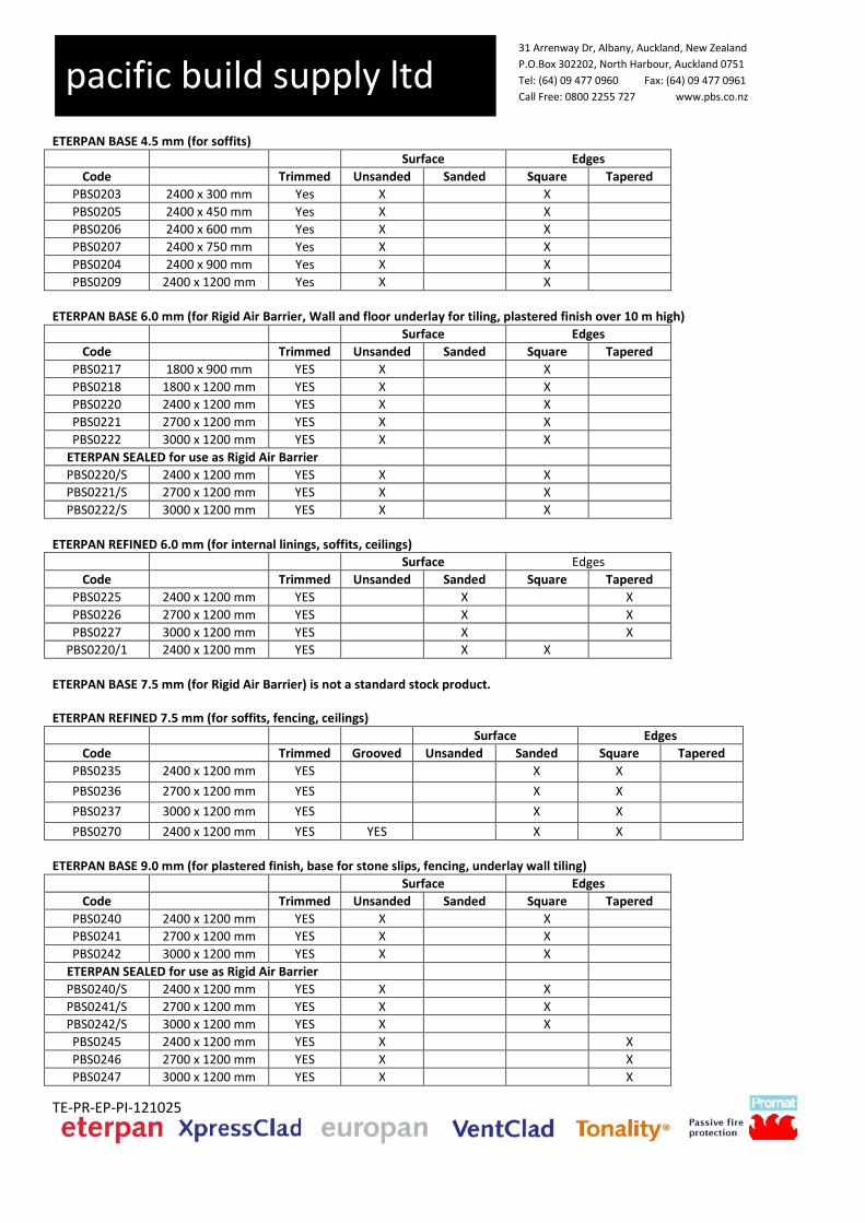
31 Arrenway Dr, Albany, Auckland, New Zealand
P.O.Box 302202, North Harbour, Auckland 0751
Tel: (64) 09 477 0960 Fax: (64) 09 477 0961
Call Free: 0800 2255 727 www.pbs.co.nz
TE-PR-EP-PI-121025
pacific build supply ltd
ETERPAN BASE 4.5 mm (for soffits)
Surface Edges
Code Trimmed Unsanded Sanded Square Tapered
PBS0203 2400 x 300 mm Yes X X
PBS0205 2400 x 450 mm Yes X X
PBS0206 2400 x 600 mm Yes X X
PBS0207 2400 x 750 mm Yes X X
PBS0204 2400 x 900 mm Yes X X
PBS0209 2400 x 1200 mm Yes X X
ETERPAN BASE 6.0 mm (for Rigid Air Barrier, Wall and floor underlay for tiling, plastered finish over 10 m high)
Surface Edges
Code Trimmed Unsanded Sanded Square Tapered
PBS0217 1800 x 900 mm YES X X
PBS0218 1800 x 1200 mm YES X X
PBS0220 2400 x 1200 mm YES X X
PBS0221 2700 x 1200 mm YES X X
PBS0222 3000 x 1200 mm YES X X
ETERPAN SEALED for use as Rigid Air Barrier
PBS0220/S 2400 x 1200 mm YES X X
PBS0221/S 2700 x 1200 mm YES X X
PBS0222/S 3000 x 1200 mm YES X X
ETERPAN REFINED 6.0 mm (for internal linings, soffits, ceilings)
Surface Edges
Code Trimmed Unsanded Sanded Square Tapered
PBS0225 2400 x 1200 mm YES X X
PBS0226 2700 x 1200 mm YES X X
PBS0227 3000 x 1200 mm YES X X
PBS0220/1 2400 x 1200 mm YES X X
ETERPAN BASE 7.5 mm (for Rigid Air Barrier) is not a standard stock product. ETERPAN REFINED 7.5 mm (for soffits, fencing, ceilings)
Surface Edges
Code Trimmed Grooved Unsanded Sanded Square Tapered
PBS0235 2400 x 1200 mm YES X X
PBS0236 2700 x 1200 mm YES X X
PBS0237 3000 x 1200 mm YES X X
PBS0270 2400 x 1200 mm YES YES X X
ETERPAN BASE 9.0 mm (for plastered finish, base for stone slips, fencing, underlay wall tiling)
Surface Edges
Code Trimmed Unsanded Sanded Square Tapered
PBS0240 2400 x 1200 mm YES X X
PBS0241 2700 x 1200 mm YES X X
PBS0242 3000 x 1200 mm YES X X
ETERPAN SEALED for use as Rigid Air Barrier
PBS0240/S 2400 x 1200 mm YES X X
PBS0241/S 2700 x 1200 mm YES X X
PBS0242/S 3000 x 1200 mm YES X X
PBS0245 2400 x 1200 mm YES X X
PBS0246 2700 x 1200 mm YES X X
PBS0247 3000 x 1200 mm YES X X

31 Arrenway Dr, Albany, Auckland, New Zealand
P.O.Box 302202, North Harbour, Auckland 0751
Tel: (64) 09 477 0960 Fax: (64) 09 477 0961
Call Free: 0800 2255 727 www.pbs.co.nz
TE-PR-EP-PI-121025
pacific build supply ltd
ETERPAN REFINED 9.0 mm (for cladding negative detail, soffits, internal linings, ceilings, fencing)
Surface Edges
Code Trimmed Unsanded Sanded Square Tapered
PBS0240/1 2400 x 1190 mm YES X X
PBS0241/1 2700 x 1190 mm YES X X
PBS0242/1 3000 x 1190 mm YES X X
PBS0245/1 2400 x 1200 mm YES X X
PBS0246/1 2700 x 1200 mm YES X X
PBS0247/1 3000 x 1200 mm YES X X
ETERPAN BASE 12.0 mm (for handrails)
Surface Edges
Code Trimmed Unsanded Sanded Square Tapered
PBS0250 2400 x 1200 mm Yes X X
PBS0252 2700 x 1200 mm Yes X X
ETERPAN REFINED 15.0 mm (for trims, handrails)
Surface Edges
Code Trimmed Unsanded Sanded Square Tapered
PBS0257 3000 x 1200 mm Yes X X
ETERPAN BASE 20.0 mm (for decks)
Surface Edges
Code Trimmed Unsanded Sanded Square Tapered
PBS0260 2400 x 1200 mm Yes X X
ETERPAN SIDING150 and SIDING180 - thickness 15.0 mm
Surface Edges
Code Trimmed Unsanded Sanded Square Tapered
PBS0606 3000 x 150mm Yes X X
PBS0600 3000 x 180 mm Yes X X
ETERPAN SIDING CEDAR – thickness 7.5 mm
Surface Edges
Code Trimmed Unsanded Sanded Square Tapered
PBS0391 3000 x 190 mm Yes X X
ETERPAN SIDING SMOOTH – thickness 7.5 mm
Surface Edges
Code Trimmed Unsanded Sanded Square Tapered
PBS0437 3000 x 190 mm Yes X X
Tolerances
Untrimmed After cutting
Thickness +/- 0.5 mm
+/- 0.5 mm
Length and width +/- 5.0 mm
+/- 1.5 mm
Squareness 3.0 mm / m 1.0 mm / m

31 Arrenway Dr, Albany, Auckland, New Zealand
P.O.Box 302202, North Harbour, Auckland 0751
Tel: (64) 09 477 0960 Fax: (64) 09 477 0961
Call Free: 0800 2255 727 www.pbs.co.nz
TE-PR-EP-PI-121025
pacific build supply ltd
4. Weight (average values, including average moisture content)
Thickness Weight
4.5 mm 6.5 kg/m2
6 mm 8.6 kg/m2
7.5 mm 10.8 kg/m2
9 mm 13.0 kg/m2
12 mm 17.3 kg/m2
15 mm 21.6 kg/m2
20 mm 28.8 kg/m2
Eterpan Siding Thickness Weight
Siding 150 15.0 mm 9.1 kg/piece
Siding 180 15.0 mm 10.9 kg/piece
Cedar 7.5 mm 5.8 kg/piece
Cedar Smooth 7.5 mm 5.8 kg/piece
5. Colours ETERPAN comes in a light beige colour. No other colours are available.
6. Testing and technical properties (average values)
Eterpan sheets are classified Type A under the requirements of AS 2908.2-1992 Cellulose Cement Products, Part 2 Flat sheets.
Eterpan has been tested by BRANZ and reported in MTR 1083 to AS 2908.2 which defines standards of performance for flat sheets of
cellulose-cement products. The results are summarised as follows:-
(i) Determination of Flexural Strength – Modulus of Rupture: results gave Eterpan a category 2 for a type A board (external use) in AS 2908.2, section 6.
(ii) Determination of Water tightness: requirements for a type A (external) sheet in AS 2908.2 met (i.e no water droplets on the reverse side of the sheet were evident).
(iii) Determination of Resistance to Hot Water Soaking: after hot water soaking the test samples did not show any visible cracks, structural alteration, or delamination as required in AS 2908.2 for type A (external sheets). The 95% confidence limit of the ratio of mean hot water MOR to mean control MOR was above 0.8 as also required.
(iv) Determination of Resistance to Heat/Rain: after heat/rain exposure, the test samples did not show any visible cracks, structural alteration, or delamination as required in AS 2908.2 for type A (external sheets).
(v) Determination of Resistance to Freeze/Thaw: after freeze/thaw exposure, the test samples did not show any visible cracks, structural alteration, or delamination as required in AS 2908.2 for type A (external sheets).
Code Compliance Eterpan has a BRANZ 50 year durability opinion, ref BDO 98/3 and meets the following performance criteria of the N.Z.B.C.
1. Durability: a. When as a non structural part of the building envelope Eterpan meets the N.Z.B.C durability requirement of 15 years
according to clause B2.3.1(b). b. When as a structural part of the building envelope Eterpan meets the N.Z.B.C durability requirement of 50 years
according to clause B2.3.1(a), when coated with a water impermeable treatment, maintained over the life of the product.
c. Eterpan is producer guaranteed against physical or mechanical deterioration for 50 years.

31 Arrenway Dr, Albany, Auckland, New Zealand
P.O.Box 302202, North Harbour, Auckland 0751
Tel: (64) 09 477 0960 Fax: (64) 09 477 0961
Call Free: 0800 2255 727 www.pbs.co.nz
TE-PR-EP-PI-121025
pacific build supply ltd
2. Hazardous Building Materials: Eterpan is a non hazardous product according to N.Z.B.C Performance F2.
Density : > 1200 kg/m³ Bending strength (24h immersed in water) // : 12.0 N/mm²
Τ : 9.0 N/mm² Frost resistance : frost resistant Reaction to fire according to ISO 1182 : Non combustible Heat and total heat release rates AS/NZS 3837 : Eterpan has performance level A Smoke development : 0 Ignition : 0 Surface Spread of Flame : 0 Heat Evolved : 0
7. Advantages • No flame spread, no fume development, no toxic gasses • Resistant to high temperatures • Water resistant • Truly monolithic core • Resistant to fungae, bacteria, insects, vermin, etc. • Resistant to many chemicals • Environmentally friendly, no harmful gas emissions • Frost resistant • High dimensional stability • Strong and rigid sheet • Versatile and easy to install
8. Working guidelines Cutting: • Pacific Build Supply Ltd operates a CNC waterjet cutting machine in Auckland that facilitates the cutting of intricate designs with minute tolerances. Please contact Pacific Build Supply Ltd for more information. For on site cutting: • With a stationary saw, slow rotation with tungsten carbide-tipped blade or fast rotation with a fluted diamond cutting blade. • With a hand circular saw (with rail), slow rotation with tungsten carbide-tipped blade or fast rotation with a fluted diamond cutting blade. • With a jigsaw with tungsten carbide-tipped tooth cutting blade • Conventional woodworking equipment can be used but in general wear faster and have lower quality edges. Edge finish: • Use a fine emery cloth or sanding block • Edges to be sealed as part of the specified architectural finish. No other requirements for edge sealing. Drilling: • For holes: carbide tipped twist drill with a 60° nose angle • For round apertures: cup drill or circular cutter, carbide-tipped The sheet should be supported around the hole to be drilled (e.g. by a wooden surface). • Cutting and drilling must take place in a dry environment. All residual dust must be removed immediately from the sheet with a dry towel to avoid permanent stains.

31 Arrenway Dr, Albany, Auckland, New Zealand
P.O.Box 302202, North Harbour, Auckland 0751
Tel: (64) 09 477 0960 Fax: (64) 09 477 0961
Call Free: 0800 2255 727 www.pbs.co.nz
TE-PR-EP-PI-121025
pacific build supply ltd
Fixing: The method and choice of the fixings (e.g. stainless steel, aluminium …) is dependent on the application and the environment.
1) Structural adhesive (concealed fixing): ETERPAN can be fixed with a structural adhesive. The back of the sheet must be sanded (sand paper P80) and sealed at the area where the adhesive is applied. The only adhesive to be used is specified by Pacific Build Supply Ltd in accordance with the Pacific Build Supply Ltd application guidelines. Further information is available from Pacific Build Supply Ltd. 2) Screwing: Use screws as specified by Pacific Build Supply Ltd. On XpressClad aluminium rails the screws are 19 mm long stainless steel self-tapping countersunk screws or 25 mm long stainless steel self tapping screws in combination with 10g stainless steel cup washers. To fix Eterpan on VentClad timber battens use 63 mm long stainless steel countersunk screws (for flushed finish) or 70 mm long stainless steel with sq drive head and stainless steel cup washers for featured fixings. Sheets need to be predrilled with the appropriate diameter. Respect the fixing patterns as specified by Pacific Build Supply Ltd. Min distance to the edge of the sheet is 15 mm and 100 and 50 mm to the edges at the corner of the sheets. 3) Nailing: In some applications, it is possible to nail Eterpan sheets. Specifications of the nails as well as fixing patterns depend on the application and can be found on the Pacific Build Supply website or by contacting Pacific Build Supply Ltd directly. Min distance to the edge of the sheet is 15 mm and 100 and 50 mm to the edges at the corner of the sheets.
Caulking: Only use products recommended by Pacific Build Supply Ltd. Non-neutral silicones or thiokols can result in staining. Health and safety aspects: While the sheets are being processed, dust will be released which may irritate airways and eyes. It is recommended that a minimum P2 dust mask and safety goggles be worn. Appropriate dust extraction or proper ventilation should be used depending on the room in which the work is being carried out or the equipment being used. Long-term exposure to dust may be harmful to health.
9. Handling
The sheets are packed on pallets. They must be kept dry during transport. The sheets must be horizontally stacked on a flat surface. The sheets must always be sufficiently supported so that they do not sag. The sheets must be stored in a dry ventilated space. If the sheets are stored outside, they must always be protected against rain by a tarpaulin or plastic sheet. If the sheets do become wet in the packing, all packaging must be removed and the sheets must be wiped dry and placed in a way that they can dry completely. A sheet must always be lifted from a stack by two people and then be carried on edge.
10. Guarantee The guarantee and the guarantee conditions are available on request from Pacific Build Supply Ltd,

1902 Home of Compassion Creche
© CIL Masterspec 2013 4238CB CELCRETE BLOCK Page 1
4238CB CELCRETE BLOCK – Rev A 1. GENERAL This section relates to the laying and reinforcing of Celcrete AAC concrete blocks on a
rigid backing over lightweight timber framing construction as shaped veneer substrate for solid plaster.
1.1 RELATED WORK Refer to 4231V PBS VENTCLAD PLASTERED FINISH CLADDING for substrate Refer to 4272 BRICK SLIP VENNER ofr waterproofing & adhesive Refer to 4280SOLID PLASTER for plastering 1.2 ABBREVIATIONS Refer to the general section 1232 INTERPRETATION & DEFINITIONS for abbreviations
and definitions used throughout the specification. The following abbreviations apply specifically to this section: AAC Autoclaved Aerated Concrete Documents 1.3 DOCUMENTS REFERRED TO Documents referred to in this section are: NZBC H1/AS1 Energy efficiency AS/NZS 1170.2 Structural design actions - Wind actions NZS 1170.5 Structural design actions - Earthquake actions - New Zealand AS/NZS 2904 Damp proof courses and flashings NZS 3101.1 & 2 Concrete structures standard - The design of concrete structures NZS 4210 Masonry construction - Materials and workmanship AS/NZS 4347.0 Damp-proof courses and flashings - method of test - General
introduction, list of methods and test specimen requirements AS/NZS 4671 Steel reinforcing materials Documents listed above and cited in the clauses that follow are part of this specification.
However, this specification takes precedence in the event of it being at variance with the cited document.
1.4 MANUFACTURER'S DOCUMENTS Manufacturer's documents related to this section are; Celcrete Block Building System technical manual - March. 2009. Manufacturer/supplier contact details; Company: CELCRETE International Limited Web: www.celcrete.net Telephone: (07) 579 5277 Fax: (07) 579 5299 Email: [email protected] Warranties 1.5 WARRANTY - MANUFACTURER/SUPPLIER Provide a material manufacturer/supplier warranty: 25 years: For materials - Provide this warranty on the manufacturer/supplier standard form. - the warranty from the date of practical completion of the contract works. Refer to the general section 1237 WARRANTIES for additional requirements. 1.6 WARRANTY - INSTALLER/APPLICATOR Provide an installer/applicator warranty:
1902 Home of Compassion Creche
© CIL Masterspec 2013 4238CB CELCRETE BLOCK Page 2
15 years: For Application - Provide this warranty on the installer/applicator standard form. - Commence the warranty from the date of practical completion of the contract works. Refer to the general section 1237 WARRANTIES for additional requirements. Requirements 1.7 NO SUBSTITUTIONS Substitutions are not permitted to any specified Celcrete concrete masonry or associated
products. 1.8 QUALIFICATIONS Blocklayers to be experienced competent builders familiar with the required Celcrete type
of block laying. 1.9 CONSTRUCTION OBSERVATION BY ENGINEER Inspection to be carried out at critical stages, including set out, reinforcing, and prior to
and during grouting. Where inspection is required as a condition of the building consent, advise the engineer when inspections are required.
Obtain the producer statements required from the engineer relating to the masonry
construction and keep with the building consent documentation. 1.10 QUALITY RECORDS Keep accurate records relating to the construction, and make the information available to
the Building Consent Authority inspector on request. Performance 1.11 WIND ZONE The design wind pressures are to NZS 3604, up to and including Extra High Wind Zone.
The details and information contained in the Celcrete technical manual are suitable for these conditions.
1.12 INSTALLATION PERFORMANCE The Celcrete installer must accept responsibility for the installation of the block forms. Quality control and assurance 1.13 INSPECTIONS Allow to inspect the whole of the work at each stage. Determine a programme for
inspections including notification when each part and stage of the work is ready for inspection prior to the work commencing. Permit representatives from Celcrete to inspect the work in progress and to take samples of their products from site.
2. PRODUCTS Materials 2.1 CELCRETE AAC BLOCKS AAC, a solid inert, lightweight masonry building material. Width: 300mm, 250mm, 200mm, 150mm 125mm & 100mm Height: 200mm and 300mm Length: 600mm 2.2 FACING/VENEER BLOCKS Block size to be suited to form of final shape required. Cut to match details and forms of original chimney on off-site from full blocks; refer to
Celcrete Block Building System manual.
1902 Home of Compassion Creche
© CIL Masterspec 2013 4238CB CELCRETE BLOCK Page 3
2.3 SCREWS 12g x 125mm stainless steel purlin fixing screws, countersunk minimum 10mm into block,
to AS 3566 and NZBC E2/AS1 Table 20. Components 2.4 THICK BED MORTAR Refer to 4272 BRICK SLIP VENEER for waterproofing and adhesive of veneer to
substrate. All other joints are glued with Celcrete mortar glue, supplied with the Celcrete Block.
2.5 SEALANT Protectosil WS 205. A silane based emulsion. Plaster system Refer to 4282 SOLID PLASTER 3. EXECUTION Conditions 3.1 DELIVERY AND STORAGE Keep products dry in transit. Take delivery of products dry and undamaged. Reject all
damaged materials. 3.2 STORAGE Deliver all materials on pallets provided. Provide dry, covered well ventilated storage on
site, clear of ground. Stack materials carefully, and protect from mechanical damage. Keep bagged materials off concrete surfaces on a timber pallet or timber dunnage.
3.3 CONFIRM LAYOUT Confirm the layout before commencing work. 3.4 TOLERANCES Construct within the tolerances set out in NZS 4210: clause 2.6.5, Tolerances and clause
2.7, Laying the units, unless specified otherwise on the drawings or in this specification. Lay blocks with jointing of consistent thickness throughout.
Lay masonry to an even, plane surface with no deviation exceeding 3mm in 3 metres on any surface in view in the finished work.
3.5 CHECK SUBSTRATE Check that the fibre cement substrate on which masonry is being built is true to line and
plumb, to ensure that work can be taken up true and plumb. 3.6 MOISTURE CONTENT Ensure that blocks are air-dry prior to laying. 3.7 PROTECTION Keep fair face block walls clean of mortar glue splashes, or stains of any kind as the work
proceeds and before any droppings set, and protected from weathering prior to sealing to avoid instances of damage and staining.
3.8 WEATHER PRECAUTIONS When extreme temperatures prevail, either below 4°C or above 27°C, make adjustments
to construction as listed in NZS 4210: clause 2.18, Cold weather construction, and clause 2.19, Hot weather construction. Do not use expansive grout in temperatures below 5°C.
Application 3.9 SELECTION For fair face walls select blocks for consistent colour, texture and lack of imperfections.
Refer to clause PROTECTION.

1902 Home of Compassion Creche
© CIL Masterspec 2013 4238CB CELCRETE BLOCK Page 4
3.10 CUTTING Cut using carbide tipped saw to provide clean, accurate cuts. 3.11 CONSTRUCTION Where shown on the drawings or where nominated below, construct veneer using
Celcrete block. Build the veneer by glueing the blocks with Celcrete mortar glue in a running bond pattern, joints not exceeding 1-2mm thick. The teeth of the trowel will spread the mortar glue to the appropriate depth. Note that all edges should be glued. Refer to Celcrete technical manual March. 2009.
3.12 CLEANING JOINTS After each block is placed, run the trowel across the joint to remove any mortar glue that
has overspilled or been squeezed out. At the end of each day scrape the wall down to remove any further spillages.
3.13 TOOLS Use the tools listed in the Celcrete Block Building System technical manual. 3.14 BRACING If in a high wind area provide sufficient temporary lateral bracing to ensure stability until
the final supporting construction is in place. 3.15 ADHERE ON COMPONENTS Use Celcrete mortar glue to attach any Celcrete components such as sills, parapet
capping, window surrounds and decorative feature work. Sills are cut at an angle of 20 degrees.
Application - finishing systems 3.16 INSPECTION The Applicator shall inspect the Celcrete surface to be coated and report to the main
contractor if the applicator believes that work cannot be completed to the required standard due to the condition of the block surface.
3.17 PROTECTION All adjoining surfaces and areas susceptible to damage from coating or paint over-spill
must be covered and protected accordingly by the applicator. 3.18 EXTERNAL ENVIRONMENTAL CONDITIONS Ensure that work is conducted within the acceptable temperature range of each product
as per the applicator and Celcrete technical data sheets. 3.19 PREPARATION OF SUBSTRATES & CORRESPONDING SURFACES Prepare all surfaces to be coated to the requirements of the coating systems' per
Celcrete technical manual. Completion 3.20 PROGRESSIVE CLEANING Clean off mortar splashes and grout spills as they occur. 3.21 FINAL CLEANING At completion, clean down block work, remove efflorescence and remove waste materials
from adjoining surfaces and floors. 3.22 REPLACE Replace damaged, cracked or marked elements. 3.23 REMOVE Remove debris, unused materials and elements from the site.

1902 Home of Compassion Creche
© CIL Masterspec 2013 4238CB CELCRETE BLOCK Page 5
4. SELECTIONS Refer to ‘Schedule of Selections’ in drawing set.

1902 Home of Compassion Creche
© CIL Masterspec 2013 4272 BRICK SLIP VENEER Page 1
4272 BRICK SLIP VENEER – Rev A 1. GENERAL This section relates to the supply, laying and fixing of non-load bearing brick; - as a non-structural decorative veneer - adhered directly to an approved substrate with a mortar based adhesive - for exterior applications - as pointed brick veneer 1.1 RELATED WORK Refer to 4231V PBS VENTCLAD PLASTERED FINISH CLADDING for substrate Appended project specific Mapei specification Documents 1.2 DOCUMENTS Refer to the general section 1233 REFERENCED DOCUMENTS. The following
documents are specifically referred to in this section: NZBC B1/AS1 Structure NZS 3604 Timber-framed buildings Documents listed above and cited in the clauses that follow are part of this specification.
However, this specification takes precedence in the event of it being at variance with the cited document.
1.3 MANUFACTURER/SUPPLIER DOCUMENTS Manufacturer's and supplier's documents relating to this part of the work:
Mapei Primer G technical data sheets Mapelastic Smart technical data sheets Mapei Kerabond technical data sheets Mapei Isolastic technical data sheets
Refer to appended job specific Mapei Specification.
Manufacturer/supplier contact details Company: Mapei Web: www.mapei.co.nz Telephone: 09 921 1994 Warranties 1.4 WARRANTY Provide warranty for:
5 years: For materials and application - Provide the warranty in the standard form in the general section 1237WA WARRANTY
AGREEMENT. - Commence the warranty from the date of practical completion of the contract works. 1.5 WARRANTY - MANUFACTURER/SUPPLIER Provide a material manufacturer/supplier warranty:
5 years: For materials - Provide this warranty on the manufacturer/supplier standard form. - Commence the warranty from the date of practical completion of the contract works. Refer to the general section 1237 WARRANTIES for additional requirements. 1.6 WARRANTY - INSTALLER/APPLICATOR Provide an installer/applicator warranty:

1902 Home of Compassion Creche
© CIL Masterspec 2013 4272 BRICK SLIP VENEER Page 2
5 years: For application - Provide this warranty on the installer/applicator standard form. - Commence the warranty from the date of practical completion of the contract works. Refer to the general section 1237 WARRANTIES for additional requirements. Requirements 1.7 QUALIFICATIONS Work to be carried out by tradesmen experienced, competent and familiar with the
materials and techniques specified. 1.8 SALVAGE OF EXISTING BRICKS The existing bricks from the demolished chimney are to be salvage for re-use, bricks to
be cleaned of all original mortar and paint. Contractor is to undertake a detailed measured survey of the existing chimney exterior
details, capping and pots so that a true replication can be achieved.
2. PRODUCTS Materials – Brick slips 2.1 INDIVIDUAL BRICK SLIPS Salvaged existing bricks from chimney, cut existing brick with a wet masonary bench saw
to a thickness of 20mm, exterior face of brick is to be retained as slip. Brick slips to be dry and free from all dust Refer to SCHEDULE OF SELECTIONS for type.
Materials - primer 2.2 SUBSTRATE PRIMER Proprietary waterproofing membrane primer to be: Mapei ‘Primer G’ 2.3 WATERPROOFING Proprietary waterproofing membrane to be: Mapei ‘Mapelastic Smart. Materials - adhesive 2.4 ADHESIVE – BRICK SLIPS Masonry Mortar Mix sand and cementitious adhesive.
Mapei ‘Kerabond Plus with Isolastic additive at 100% Refer to SELECTIONS.
Materials - sealer for brick slip 2.5 SEALER When required use a long life penetrating masonry sealer suitable for brick products after
installation. Accessories 2.6 CAPSTONES CapStones to be AAC formed to profiles detailed in drawings and to match existing
original chimney. Refer to SCHEDULE OF SELECTIONS.
2.7 SILLS/DADO DETAILS Sills/dado details to be AAC formed to profiles detailed in drawings and to match existing
original chimney.. Refer to SCHEDULE OF SELECTIONS.

1902 Home of Compassion Creche
© CIL Masterspec 2013 4272 BRICK SLIP VENEER Page 3
3. EXECUTION Conditions 3.1 WET WEATHER Keep brick slips and AAC forms dry at all times prior to laying. Protect the top row of
uncompleted stone walls. Protect freshly laid stonework during interruption through rain and at completion of each day's work.
3.2 KEEP FACE WORK CLEAN Keep clean during erection and until completion of the contract works. Turn back scaffold
boards at night and during heavy rain. Do not rub face work to remove stains. 3.3 COLOUR MIXING Check all bricks delivered to site for colour variation, prior to commencing work. Ensure
veneers are thoroughly blended from several cartons to ensure an even colour spread throughout the work.
Substrate 3.4 SUBSTRATE - GENERAL Confirm the substrate is suitable for the veneer application, installed to the manufacturer's
installation requirements, as required by NZBC B1/AS1 and to meet stone cladding manufacturers requirements.
Preparation 3.5 SURFACE PREPARATION Ensure the substrate is dry and free of all dust, paint or other surface contaminants
before commencing the veneer installation. 3.6 WATERPROOFING / SUBSTRATE PRIMER When a primer or waterproofing membrane is required ensure product is compatible with
the chosen adhesive and complies with manufacturer's instructions. Installation – brick slip veneer 3.7 PRIOR TO LAYING Ensure a random mix by opening at least three boxes to select brick slips. Achieve
running bond look by using slips in straight coarses, smooth surfaces to face outward, cut face adhered. Do not lay dis-similar modules together.
3.8 BONDING TO SUBSTRATE Use flexible adhesive mortar as recommended by the supplier to bond the veneer to the
substrate and comply with manufacturer's requirements. Press and bond brick slip firmly to the substrate by giving it a firm wriggle. The mortar will squash up around the brick slip and can be either brushed or scratched back after 30 to 60 minutes, or pointed out to suit the required look.
3.9 INSTALL TO A POINTED FINISH Install brick slips to allow for a pointed finish, form a 10mm perpend between all bricks
suitable for pointing to match existing. 3.10 INSTALL CORNER PIECES Apply the corner brick pieces first. Use a chalk line at approximately 300mm centres to
keep the levels straight and to give a guideline. Apply sufficient mortar to the back of the brick veneer piece with a 6mm to 8mm notched trowel and press firmly onto the wall.
3.11 EXCESS MORTAR ADHESIVE Avoid getting adhesive onto the surface of the brick veneer. Ensure any excess mortar
adhesive is cleared off regularly using a sponge or brush.

1902 Home of Compassion Creche
© CIL Masterspec 2013 4272 BRICK SLIP VENEER Page 4
3.12 CONTROL JOINTS Where manufactured individual brick types cross a control joint, apply mortar to the
longest side of the veneer only and avoid mortar crossing the join in the sheet. Completion 3.13 PROGRESSIVE CLEANING Clean off all contaminants from the face work immediately after they occur. 3.14 LEAVE Leave work to the standard required by following procedures. 3.15 REMOVE Remove any temporary structures, all debris, unused materials and elements from the
site. 4. SELECTIONS Refer to ‘Schedule of Selections’ in drawing set.


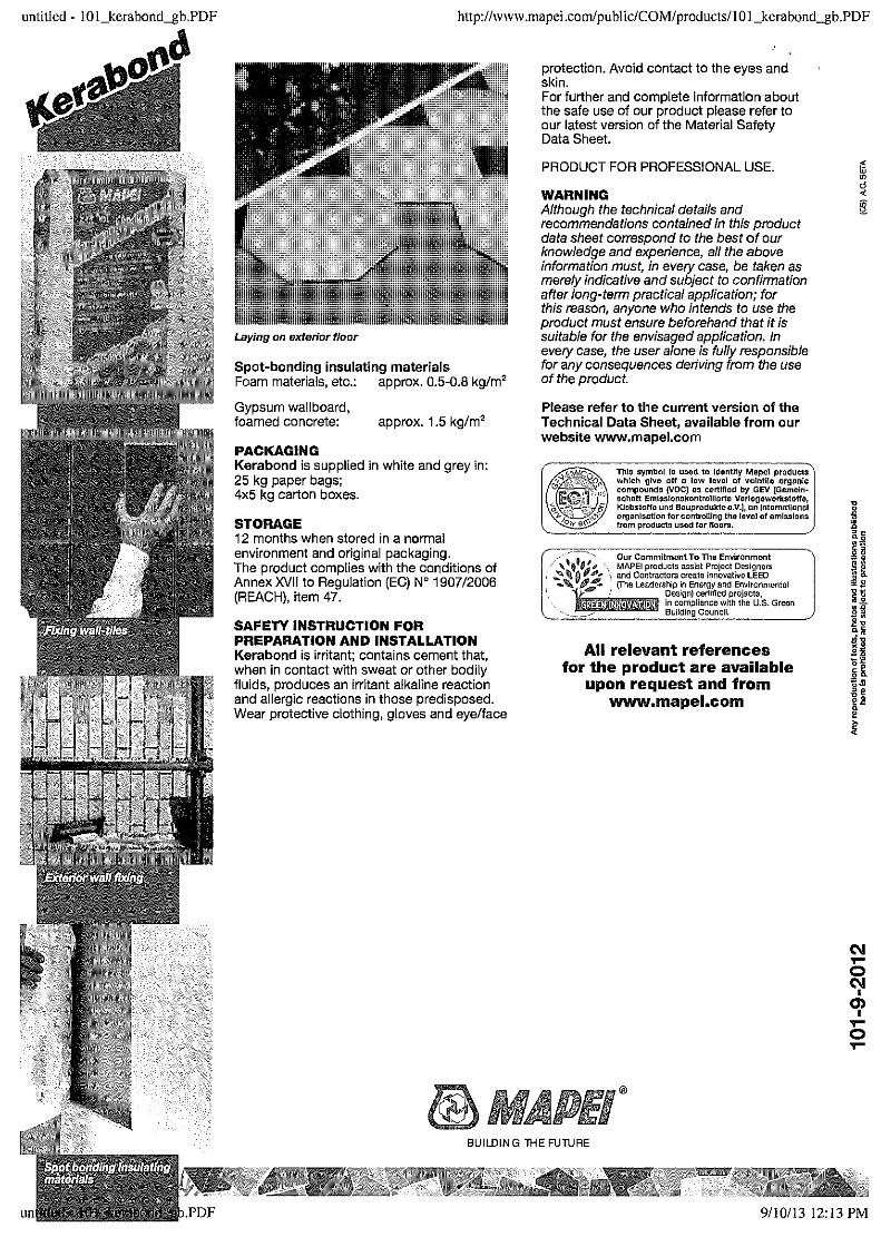


1902 Home of Compassion Creche
© CIL Masterspec 2013 4282 SOLID PLASTER Page 1
4282 SOLID PLASTER – Rev A 1. GENERAL This section relates to the repair of existing coatings of cement plasters, and new skim
coats, applied by hand to external backgrounds, over: - brick - concrete substrates
The original specification for the external plaster is given as:
Repair and recoating work shall match materials, mixes, colours to the fullest extent possible. The exact mix will be determined on site with reference to the existing, and by sample panels.
Related work 1.1 RELATED SECTIONS Refer to 4231 PBS VENTCLAD PLASTERED FINISH CLADDING for substrate Refer to 4272 BRICK SLIP VENEER for adjacent cladding on substrate Documents 1.2 DOCUMENTS REFERRED TO Documents referred to in this section are: AS 2592 Gypsum plaster for building purposes NZS 3103 Sands for mortars and plasters NZS 3113 Chemical admixtures for concrete NZS 3121 Water and aggregate for concrete NZS 3122 Portland and blended cements (General and special purpose) NZS 4251.1 Solid plastering: Cement plasters for walls, ceilings and soffits BS 890 Building limes Documents listed above and cited in the clauses that follow are part of this specification.
However, this specification takes precedence in the event of it being at variance with the cited document.
Requirements 1.3 FINISH PANEL Provide sample panels of each mix and finish specified. Include example of specified trim
and junction details. Obtain approval of colour and texture before starting work.. Sample panel size: 500mm x 500mm cement board.
Allow for six sample boards to develop render to match existing. 1.4 MATERIALS AND EXECUTION Plastering work to NZS 4251.1 Solid plastering.
1902 Home of Compassion Creche
© CIL Masterspec 2013 4282 SOLID PLASTER Page 2
2. PRODUCTS Materials 2.1 BONDING AGENT Use to form gauging liquid with water:
Bond coat: 1:1 Flanking and finish coats: 1:2
Use in accordance with the bonding agent manufacturer's requirements, maintaining the approved dosage throughout the work.
2.2 ADMIXTURES To NZS 3113. Use in accordance with the admixture manufacturer's requirements,
maintaining the approved dosage throughout the work. 2.3 SAND To NZS 3103, the grading limits of NZS 4251.1 clause 2.2.2.4 Sand, and suitable for the
nominated plaster mix. Obtain from a single source, uniform in composition and colour. Chloride levels to not exceed 0.04% by dry weight of sand.
Submit service records of sands proposed in accordance with NZS 3103, clause 8.1 and
confirm that they comply. Prevent contamination or segregation of sand in storage. Do not allow it to become more than slightly damp.
2.4 CEMENT Portland Cement to NZS 4251.1 clause 2.2.2.3 Cement. 2.5 WATER To NZS 3121, or local town supply. Finishes - plaster systems 2.6 PLASTER MIXES To NZS 4251.1 table 3 Mixes for plaster (by volume), or as determined by test panels.. 3. EXECUTION Conditions 3.1 STORE MATERIALS Store materials in conditions ensuring adequate protection from contamination or
deterioration. 3.2 PLASTERING CONDITIONS To NZS 4251.1 clause 2.1.7 Air temperature. Carry out plastering under conditions (not
too sunny, windy or freezing) which will not adversely affect the finished work. Complete in sufficient time to enable subsequent finishes to be applied under the proper conditions.
3.3 DO NOT BEGIN Do not begin laying up until: - Work that could damage the plaster is complete. 3.4 SOURCE OF MATERIALS Supply materials from the same source. 3.5 PROTECT Protect existing and adjoining work and surrounds, with boards and dust sheets. Clean
off immediately droppings and mortar splashes on finished work. 3.6 PLANT AND TOOLS Clean plant and tools to ensure they are free of previous mixes (especially gypsum). 3.7 PROPRIETARY PLASTERS

1902 Home of Compassion Creche
© CIL Masterspec 2013 4282 SOLID PLASTER Page 3
Proprietary plaster mixes are not to be used. 3.8 WORKING TIME Do not use mixes after initial set has occurred. Do not retemper mixes. 3.9 JOINING UP If joining up is unavoidable in large areas of work, make junctions so that they are
concealed in the finished work. 3.10 SURFACE TOLERANCES Gradual undulations over the surface and measured between rise and hollow as follows:
Trowelled wall surfaces: Not exceeding 3mm over a 1200mm straight edge Textured wall surfaces: Not exceeding 3mm over a 900mm straight edge
No abrupt deviations permitted. Take particular care where the surface has light hitting it at an acute angle.
3.11 THICKNESS OF PLASTER Use the plaster coat thicknesses for the different backgrounds to NZS 4251.1, unless
dimensioned otherwise on the drawings. 3.12 ALIGNMENT Finish surfaces evenly to line or level, with angles and corners correct and walls and
reveals plumb and square. Conditions - background 3.13 CHECK BACKGROUND Ensure that backgrounds and adjoining surfaces are, after the preparation called for in
this section, of the required standard. Check all existing plaster for soundness, and make all repairs deemed necessary by the architect.
3.14 PREPARE SURFACE Before plastering is commenced, eliminate surface contaminants, remove dust and debris
and make good any defects in the background which may adversely affect the quality of the plaster coating.
3.15 IRREGULARITIES Hack off excessive projections. Fill voids, hollows and honeycomb with a mix not
stronger than the background or weaker than the first coat. 3.16 ACCEPTANCE OF BACKGROUNDS Do not commence work until the background is of the required standard. Application - preparing the surface 3.17 CLEAN SURFACE Remove oils, greases, retarders and loose material and leave the surface dust free and
clean. Remove paint from already painted surfaces. 3.18 EMBEDDED ITEMS Sheath or wrap water pipes and wastes passing through walls, with strip material, to
permit thermal movement. 3.19 BONDING AND KEY FOR DENSE CONCRETE Roughen dense concrete to provide a mechanical key by removing 3mm of the surface to
expose the aggregate. Apply the bond coat containing the specified bonding agent thrown onto the concrete face.
3.20 BONDING AND KEY FOR BRICKWORK Rake out joints to a depth of 15mm if not already rough jointed. Apply the bond coat
containing the specified bonding agent thrown onto the face.

1902 Home of Compassion Creche
© CIL Masterspec 2013 4282 SOLID PLASTER Page 4
3.21 CONTROL SUCTION Control suction by dampening if necessary but without over-wetting. Allow the surface to
dry back to a surface-dry condition before plastering. Application - joints and junctions 3.23 CONTROL JOINTS Provide movement control joints in the plaster to coincide with movement joints in the
background and/or junctions between dissimilar backgrounds in the same plane and/or where shown on the drawings. Galvanized mesh or lath shall not be continuous across control joints.
3.24 SECRET CONTROL JOINTS Form cut joints 3mm wide through the flanking coat plaster to the background. Fill the cut
with sealant, following the sealant manufacturer's requirements for primer and masking, before applying the finish coat to provide a secret joint.
Application - trim 3.26 FIX CORNER SECTIONS Fix specified corner sections to external angles, as required by the manufacturer for the
appropriate background. 3.27 FIX CASING BEADS Fix specified casing beads at edge terminations of plaster not covered by other trim, as
required by the manufacturer for the appropriate background. 3.28 FORM ARRISES Where sections or beads are not specified: - form arrises with 6mm pencil rounds - soften down severe arrises by rubbing with a wet trowel when finishing. 3.29 CHECK FLASHINGS Ensure that flashings, including flashings to recessed sills are in place before, or are fitted
as the coating proceeds so the completed work is completely watertight. 3.30 KEYING Press plaster through the apertures of metal lath, wings of casing beads and corner
sections. Application - plaster systems 3.31 PROPORTION AND MIXES Refer to SELECTIONS for plaster thickness and finish. 3.32 WATERPROOF RENDERING Include waterproofing admixture as specified and as required by the manufacturer. Do
not plug or puncture the waterproof render. 3.33 FLANKING COAT AND FINISHING COAT, SOLID BACKGROUNDS Apply in 2 coats over the bond coat to achieve a true surface in any direction with not
more than 3mm deviation from a straight edge 1200mm long and a total thickness of 18mm maximum.
Application - curing 3.34 CURING Confirm the curing and protection systems to be applied to fresh plaster coats. Plastering
not to begin until systems are confirmed. 3.35 PROTECT ADJOINING WORK Protect existing and adjoining work from damage during plastering. Mask adjacent
windows and provide temporary covering if necessary. Remove droppings and mortar

1902 Home of Compassion Creche
© CIL Masterspec 2013 4282 SOLID PLASTER Page 5
splashes as the work proceeds. 3.36 MOIST CURING, CEMENT BASED WORK Cure by preventing rapid or uneven drying out for a suitable period to NZS 4251.1 clause
2.5 Application and curing of plaster coats, and appendix D Plaster on curing. Bond Coat: Minimum 48 hours moist curing and 24 hours drying Flanking Coat: Minimum 48 hours moist curing and 72 hours drying Finish Coat: Minimum 72 hours moist curing depending on ambient temperatures Do not alter the above curing times. Completion 3.37 PROTECT FINISHED WORK Protect finished work from sun, wind, frost, rain and hail and from damage by building
operations or other causes. Provide temporary coverings if necessary. 3.38 REINSTATE Reinstate damaged or marked areas. 3.39 LEAVE Leave adjacent materials, fittings and finishes clean and to the standard required by
following procedures. 3.40 REMOVE Remove debris, unused materials and elements from the site. 4. SELECTIONS Refer to ‘Schedule of Selections’ in drawing set.

1902 Home of Compassion Creche
© CIL Masterspec 2013 SEP 4311 PROFILED METAL ROOFING Page 1
4311 PROFILED METAL ROOFING – Rev A 1. GENERAL This section relates to the supply and fixing of proprietary overlap rigid sheet metal
profiled roofing complete with accessories. 1.1 RELATED WORK Refer to 4311C CALDER STEWART EUROTRAY for tray roofing Refer to 7411C RAINWATER SPOUTING SYSTEMS for rainwater disposal 1.2 ABBREVIATIONS Refer to the general section 1232 INTERPRETATION & DEFINITIONS for abbreviations
and definitions used throughout the specification. The following abbreviations apply specifically to this section: BMT Base metal thickness NZMRM New Zealand Metal Roofing Manufacturers Inc MS Modified silyl Documents 1.3 DOCUMENTS Refer to the general section 1233 REFERENCED DOCUMENTS. The following
documents are specifically referred to in this section: NZBC E2/AS1 External Moisture AS/NZS 1170.2 Structural design actions - Wind actions AS 1397 Steel sheet and strip - hot-dipped, zinc-coated or aluminium/zinc-
coated NZS 2295 Pliable, permeable building underlays AS 3566 Self-drilling screws for the building and construction industries NZS 3604 Timber-framed buildings AS/NZS 4200.1 Pliable building membranes and underlays - Materials AS/NZS 4534 Zinc and zinc/aluminium-alloy coatings on steel wire AS/NZS 4389 Safety Mesh NZMRM - CoP NZ Metal roof and wall cladding - Code of practice (CoP) 1.4 MANUFACTURER'S DOCUMENTS Manufacturer's and supplier's documents relating to work in this section are: New Zealand Steel Copies of the above literature are available from New Zealand Steel Web: www.nzsteel.co.nz Email: ~ Telephone: 09 375 8999 Warranties 1.5 WARRANTY - INSTALLER/APPLICATOR Warrant this work under normal environmental and use conditions against
weatherproofing failure. 5 years: from the date of completion of the roof Form: Roofing installers standard form Include a copy of the roofing manufacturers' maintenance requirements with the warranty. Refer to the general section 1237 WARRANTIES - INSTALLER/APPLICATOR for
additional requirements. 1.6 WARRANTY - MANUFACTURER/SUPPLIER Warrant this work under normal environmental and use conditions against materials
failure.

1902 Home of Compassion Creche
© CIL Masterspec 2013 SEP 4311 PROFILED METAL ROOFING Page 2
15 years For failure of coating adhesion 15 years For weatherproofing by material penetration Form: Roofing manufacturers standard form Requirements 1.7 QUALIFICATIONS Carry out work with experienced, competent installers familiar with the products being
used and with appropriate qualifications such as the National Certificate in Metal Roofing and Cladding.
Performance 1.8 CO-ORDINATE Co-ordinate to ensure substrate and preparatory work is complete and other work
programmed in the order required for access and completion of the roof. Ensure that all necessary members are positioned so that flashings can be fastened at both edges through the roof profile or cladding to the primary structure.
1.9 PERFORMANCE Accept responsibility for the weather-tight performance of the completed roofing system,
including penetrations through the roof and junctions with walls and parapets. 1.10 FIXINGS, WIND Design and use the fixings appropriate for the design loads of this site; refer to general
section 1220 PROJECT for details of wind zone. Allow for specific loadings at corners and the periphery of the roof, where localised pressure factors apply.
Performance - Wind (design by contractor) 1.11 DESIGN PARAMETERS - NON SPECIFIC DESIGN Design the installation to the wind zone parameters of NZS 3604, table 5.4. Refer to general section 1220 PROJECT for details. 2. PRODUCTS Materials 2.1 UNDERLAY Breather type kraft paper laminates to NZS 2295. 2.2 HOT-DIPPED ALUMINIUM/ZINC COATED STEEL, UNPAINTED Formability G550 steel sheet coated to AS 1397. 2.3 FLASHINGS GENERALLY To E2/AS1, 4.0 Flashings. Formable grade 0.55mm BMT for galvanized,
aluminium/zinc-coated and pre-painted steel, and 0.9mm for aluminium (or 0.7mm for small aluminium flashings) to the same standards as the profiled sheets, notched where across profile or provided with a soft edge.
Components 2.4 FASTENERS GENERALLY Minimum Class 4 and durability not less than the roofing material being fixed. Screw
fasteners to be head stamped identifying the manufacturer and class. 2.5 FIXING CLIPS Galvanized steel (powder coated for aluminium) to suit the material and profile of the rigid
sheet and location as required by the roofing manufacturer. Fix to steel with 16mm x 10 gauge galvanized wafer head self-drilling screws and to timber with 30mm x 10 gauge galvanized wafer head screws to NZBC E2/AS1, 8.4.9.

1902 Home of Compassion Creche
© CIL Masterspec 2013 SEP 4311 PROFILED METAL ROOFING Page 3
2.6 FIXING SCREWS To AS 3566. Screws appropriate to the roofing material and the supporting structure, as
required by the roofing manufacturer and with a minimum Class 4 durability and not less than the material being fixed. Screws into timber to penetrate by minimum 30mm.
2.7 RIVETS Sealed aluminium, minimum diameter 4mm, for use with zinc coated, zinc/aluminium
coated or aluminium roofing. Accessories 2.8 SEALANT Neutral Curing silicone or MS polymer sealant as required by the roofing
manufacturerand used as directed. 2.9 CLOSURE STRIPS Compressible, closed cell profiled foam strips to fit the sheet profile. 2.10 LAP SEALING TAPE Closed cell self adhesive nitrile tape. 3. EXECUTION Conditions 3.1 INSPECTION Inspect the roof framing and supporting structure to ensure that it is complete and fully
braced ready for roofing and free from any misalignments or protrusions that could adversely affect the roofing.
3.2 FRAMING TIMBER MOISTURE When continuous metal cladding etc. Runs along a long continuous timber member and
is directly fixed to it, the timbers equilibrium moisture content (EMC) to be 18% or less. For flashings in this situation (sometimes called transverse flashings) the framing EMC to be maximum 16%, and preferably as low as 12%. Transverse flashings can be temporarily tacked in place and final fixing done when moisture content is acceptable.
3.3 STORAGE Take delivery of and accept packs of roofing undamaged on delivery. Reject all damaged
material. Store on a level firm base with packs well ventilated and completely protected from weather and damage. Do not allow moisture to build up between sheets. If sheet packs become wet, fillet or cross stack to allow air movement between sheets.
3.4 HANDLING Avoid distortion and contact with damaging substances, including cement. Do not drag
sheets across each other and other materials. Protect edges and surface finishes from damage. Use soft, flat soled shoes when fixing and for all other work on the roof.
3.5 SEPARATION Place isolators between dissimilar metals, also separate roofing from treated timber and
cement based materials. Do not use unpainted lead sheet or copper in contact with or allow water run-off onto galvanized or Zincalume® materials.
Application 3.6 LAY ROOF UNDERLAY Fit and lap roofing underlay over the existing sarking. Lay underlay horizontally or
vertically with a 150mm side lap, oversailing the spouting and/or gutters by 10mm. 3.7 SET-OUT Carefully set out with consideration of the position of side laps to take account of the line
of sight. Ensure all sheets are square and oversailing the gutter true to line. Check during fixing to eliminate creep or spread and string lines along purlin centres to keep

1902 Home of Compassion Creche
© CIL Masterspec 2013 SEP 4311 PROFILED METAL ROOFING Page 4
fastenings in line. 3.8 END LAPS End laps are not permitted, except where specifically detailed. 3.9 MOVEMENT JOINTS Fixing and jointing to conform with the roofing manufacturer's requirements for thermal
movement. Over timber framing, transverse flashings (those running long continuous framing
members) to have expansion joints at maximum 12 centres. 3.10 FIXING GENERALLY Install and fix in accordance with the NZMRM - CoP requirements, and to roofing
manufacturer's recommendations. Paint colour matched fixings and accessories before installation.
3.11 MARKING AND CUTTING Cut only by shearing tools. Do not use black lead pencils for marking aluminium/zinc
coated products. 3.12 FIX SHEETS Fix sheets in place using the fastening system required by the roofing manufacturerfor
specified profiles, making due allowance for dynamic local wind pressures on the building and thermal movement in the sheet.
3.13 STOP ENDS AND DOWNTURNS Form stop-ends at the upper end of sheets. Form downturns at the gutter line where the
roof pitch is less than 8 degrees. Form using purpose made tools. 3.14 FLASHINGS Flash roof to parapets, walls and penetrations to detail. Where no detail is provided flash
to NZMRM - CoP recommendations and the roofing manufacturer's requirements. Cut accurately and fix using sealant and rivets to detail and to the roofing manufacturer's requirements to form a weatherproof cover. For highly visible flashings, plan joints/junction to take account of the aesthetic requirements.
3.15 USE OF SEALANTS Select and use sealants only as recommended by the roofing manufacturer. Apply
sealant in two narrow beads transversely across flashing intersections, close to the two edges. Avoid exposing sealant on outside surfaces.
3.16 FLASHING PENETRATIONS Flash all penetrations through the roof. Fit pipe flashings with a proprietary collar flashing
to manufacturer's requirements, with other penetrations flashed as detailed and to provide a weathertight installation. Ensure that flashings are set to avoid any ponding of water.
3.17 INSTALL RIDGING Install ridging by fastening to the purlins through the leading edge of the roofing to
manufacturer's requirements. Completion 3.18 REPLACE Replace damaged or marked elements. 3.19 LEAVE Leave this work complete with all necessary flashings, undercloaks, valleys, ridges and
hips all properly installed as the work proceeds so the finished roof is completely weathertight.
3.20 REMOVE Remove trade rubbish and unused materials from the roof and surrounds daily during the

1902 Home of Compassion Creche
© CIL Masterspec 2013 SEP 4311 PROFILED METAL ROOFING Page 5
work. Sweep down at the end of each day, and clean out spoutings, gutters and rainwater pipes on completion of the roof. Remove debris, unused materials and elements from the site.
4. SELECTIONS Refer to ‘Schedule of Selections’ in drawing set.

1902 Home of Compassion Creche
© CIL Masterspec 2013 SEP 4311C CALDER STEWART EUROTRAY® Page 1
4311C CALDER STEWART EUROTRAY® - Rev A 1. GENERAL This section deals with the supply and fixing of Calder Stewart Roofing Ltd Eurotray®
complete with accessories. It includes:
- Overlap rigid sheet metal profiled roofing to match original design as shown in heritage photos.
Photo of original bay roof 1.1 RELATED WORK Refer to 7411 RAINWATER SPOUTING SYSTEMS for rainwater disposal Refer to 4337 PLYWOOD ROOFING for substrate Refer to 4821 FLASHINGS 1.2 ABBREVIATIONS The following abbreviations are used throughout this part of the specification: BMT Base metal thickness NZMRM New Zealand Metal Roofing Manufacturers Inc Documents 1.3 DOCUMENTS Refer to the general section 1233 REFERENCED DOCUMENTS. The following
documents are specifically referred to in this section:: NZBC E2/AS1 External moisture NZBC E2/VM1 External moisture AS/NZS 1170.2 Structural design actions - Wind actions NZS 3604 Timber-framed buildings AS 1397 Steel sheet and strip - hot-dipped, zinc-coated or aluminium/zinc-
coated AS/NZS 2269.0 Plywood - Structural - Specifications AS 4040.0 Methods of Testing Sheet Roofing and Wall Cladding AS 4040.1 Resistance to Concentrated Loads AS 4040.2 Resistance to Wind Pressure for non-Cyclonic Regions EN 988 Specification for zinc alloy sheet and strip NZMRM NZ Metal roof and wall cladding - Code of practice 1.4 MANUFACTURER/SUPPLIER DOCUMENTS Manufacturer's and supplier's documents relating to this part of the work: Calder Stewart Roofing Technical Literature Manufacturer/supplier contact details Company: Calder Stewart Roofing Ltd Web: www.roofer.co.nz Email: [email protected] Telephone: 0800 438 768

1902 Home of Compassion Creche
© CIL Masterspec 2013 SEP 4311C CALDER STEWART EUROTRAY® Page 2
Warranties 1.5 WARRANTY Warrant this work under normal environmental and use conditions against failure of
weatherproofing and materials Perforate: 15 years Coatings: 15 years Workmanship: 5 years From: Date of practical completion Provide warranties on Calder Stewart Eurotray® Products standard Warranty Form. Requirements 1.6 NO SUBSTITUTIONS Substitutions are not permitted to any specified Calder Stewart Eurotray® system, or
associated components and products. 1.7 QUALIFICATIONS Roofers to be Calder Stewart Eurotray® Products' Approved Installers. A list of
approved installers can be obtained from the Calder Stewart Eurotray® Products website, by telephone or from the local Calder Stewart Eurotray® Products branch.
Web: www.roofer.co.nz Telephone: Freephone 0800 438 768 1.8 HERITAGE IMAGE Contractor is to sight the photographic image in the drawing set of the original bay
window roof area, the standing seam pattern is to be replicated in the new roof. Compliance information 1.8 PRODUCER STATEMENTS On completion of work Calder Stewart Roofing Ltd will arrange inspection and issue a
Site Specific Producer Statement to confirm that the system has been installed in accordance with Calder Stewart's recommendations and good trade practice.
Performance 1.9 FIXINGS, WIND Design and use the fixings appropriate for the wind zone (R) and topographical
classification (T) of this site and building height; as required by NZS 3604 and the wind loads on various wall areas as given by AS/NZS 1170.2. Allow for specific loadings at corners and the periphery of the roof, where localised pressure factors apply. Do not use angle seam in very high wind zones without specific design acceptance.
1.10 CO-ORDINATE Co-ordinate to ensure substrate and preparatory work is complete and other work
programmed in the order required for access and completion of the roof. 1.11 PERFORMANCE Accept responsibility for the weather-tight performance of the completed roofing system,
including all penetrations through the roof and junctions with walls and parapets. 2. PRODUCTS Materials 2.1 PLYWOOD SUBSTRATE Plywood thickness 12.5mm minimum, H3 treated, CPD grade. 2.2 UNDERLAY Breather type kraft paper laminates to NZS 2295.
1902 Home of Compassion Creche
© CIL Masterspec 2013 SEP 4311C CALDER STEWART EUROTRAY® Page 3
2.3 HOT-DIPPED ALUMINIUM/ZINC COATED STEEL, UNPAINTED Formability G300 steel sheet coated to AS 1397. 2.4 EUROTRAY® PROFILES Eurotray® profiles are tested to AS4040 and NZBC E2/VM1. Standard tray rib centres to
be between 517mm and 528mm wide for Angle and Double Standing Seam, 565mm for Roll Cap and Roll Seam.
2.5 FLASHINGS GENERALLY To NZBC E2/AS1, 4.0 Flashings. Formable grade flashings, material to match selected
roofing or cladding, to the same standards as the profiled sheets, notched where across profile. Refer to SELECTIONS for details.
2.6 FLASHINGS TO VERGE, RIDGE AND HIP Supplied by the roofing manufacturer to match or to suit the roofing. Components 2.7 FASTENERS GENERALLY Durability of all fasteners not less than the roofing material being fixed. 2.8 FIXING CLIPS Clips shall comply with NZBC E2/AS1: 8.4.9 Fixings: trough profile. Clips to suit the
material and profile of the Eurotray® sheet to be installed prior to installation of the trays. Fix clips at no more than 600mm spacing through plywood with selected fasteners. For
high and very high wind load areas reduce clip spacing to 400mm. 2.9 FIXING SCREWS Each clip will be fixed with a 10 gauge by 30mm counter sunk screw (minimum). Screws
to be manufactured from material appropriate to the roofing material and the supporting structure, as required by Calder Stewart Roofing and with durability no less than the material fixed.
2.10 RIVETS Minimum diameter 4.0mm sealed rivets. For both Stainless steel and Titanium Zinc
roofing materials, use stainless steel rivets. Copper roofing material, use copper rivets. Aluminium/Zinc coated steel and aluminium roofing materials, use aluminium rivets.
Accessories 2.11 SEALANT Neutral curing silicone or polymer sealant. 3. EXECUTION Conditions 3.1 INSPECTION Inspect the roof framing and supporting structure to ensure that it is complete and fully
braced ready for plywood substrate and roofing. 3.2 FRAMING TIMBER MOISTURE When continuous metal cladding etc. Runs along a long continuous timber member and
is directly fixed to it, the timbers equilibrium moisture content (EMC) to be 18% or less. For flashings in this situation (sometimes called transverse flashings) the framing EMC to be maximum 16%, and preferably as low as 12%. Transverse flashings can be temporarily tacked in place and final fixing done when moisture content is acceptable.
3.3 PLYWOOD SUBSTRATE Plywood to be a minimum of 12.5mm thick and complying with AS/NZS 2269.0, minimum
CPD grade with the sanded side upwards. Treated H3 with waterborne CCA treatment
1902 Home of Compassion Creche
© CIL Masterspec 2013 SEP 4311C CALDER STEWART EUROTRAY® Page 4
and kiln dried after treatment. Lay with the face grain at right angles to the supports, staggered joints (brick bond) with all edges of the sheets fully supported. Fix with 10 gauge x 50mm stainless steel countersunk head screws, with a 3mm gap between all sheets. Fix at 150mm centres on edges and 200mm in the body of the sheets.
3.4 STORAGE Take delivery of and accept packs of roofing dry and undamaged on delivery. Reject all
damaged material. Store on a level firm base with packs well ventilated and completely protected from weather and damage. Do not allow moisture to build up between sheets.
3.5 HANDLING Avoid distortion and contact with damaging substances, including cement. Do not drag
sheets across each other and other materials. Protect edges and surface finishes from damage. Use soft, flat sole shoes when fixing and for all other work on the roof.
3.6 SEPARATION Isolate dissimilar materials in close proximity as necessary by painting the surfaces or
fitting separator strips of compatible materials. Place isolators between metals and treated timber and cement based materials. Do not use lead sheet in contact with or allow water run-off onto galvanized or aluminium/zinc coated steel.
Application 3.7 SET-OUT Carefully set out with side laps away from the prevailing wind, with the widths of end
sheets the same, all sheets square and oversailing the gutter true to line. Check during fixing to eliminate creep or spread and string lines along purlin centres to keep fastenings in line.
3.8 FORMING Form stop-ends and downturns to the roofing manufacturer's details and techniques
using the required tools. 3.9 SEAL CUT EDGES In very severe marine environments seal cut edges of pre-coated steel sheet with edge
protection lacquer before fixing to the roofing manufacturer's requirements. 3.10 END LAPS End laps are not permitted, except where specifically detailed and prior agreement given
by Calder Stewart Roofing. 3.11 THERMAL MOVEMENT Roof fixing and jointing to conform with Calder Stewart Roofing requirements for thermal
movement. NZBC E2/AS1: 8.4.10 Allowance for expansion, notes specific design is required for lengths exceeding 18 metres.
Sliding clips to be used where roofing material exceeds 4 metres in length. 3.12 FIXING GENERALLY Install and fix in accordance with the NZMRM NZ Metal roof and wall cladding - Code of
practice recommendations, and to the roofing manufacturer's required fixing patterns and details for each area of the building roofing. Use only screws as required by the roofing manufacturer. Paint colour matched fixings and accessories before installation.
3.13 FIX UNDERLAY Fit a 200mm wide strip of underlay between the plywood substrate and any drip edge
flashing with a 15mm over-sail into gutter. Once drip edge flashings are installed fit and lap roofing underlay over the plywood substrate and the drip edge flashing to the underlay manufacturer's requirements..
3.14 MARKING AND CUTTING Cut only by shearing tools. Do not use black lead pencils for marking aluminium/zinc
coated products.

1902 Home of Compassion Creche
© CIL Masterspec 2013 SEP 4311C CALDER STEWART EUROTRAY® Page 5
3.15 FIX SHEETS Fix sheets in place using the clips as previously set out. For Roll Cap and Roll Seam, fit
cap flashings once sheets have been fitted. 3.16 FLASH Flash roof to parapets, walls and penetrations to detail, to the NZMRM NZ Metal roof and
wall cladding - Code of practice recommendations and the roofing manufacturer's requirements. Cut accurately and fix using sealant and rivets to detail and to the roofing manufacturer's requirements to form a weatherproof cover.
3.17 FIX RIDGES AND HIPS Cut accurately and fix using primary fasteners to the purlins. Join using sealant and
rivets to detail and to the NZMRM NZ Metal roof & wall cladding - Code of practice. All laps 150mm minimum.
3.18 FIX VERGE AND CAP FLASHINGS Cut accurately and fix using primary fasteners to the purlins. Join using sealant and
rivets to detail and to the NZMRM NZ Metal roof & wall cladding - Code of practice. All laps 150mm minimum.
3.19 PENETRATIONS Flash and overflash all penetrations through the roof. 3.20 PENETRATIONS AND JUNCTIONS Check that adjoining walls and parapets are prepared ready for the installation of the
roofing. Confirm that openings have been prepared ready for the installation of skylights and other penetrations through the roof. Required work includes the following:
- underlay turned up at wall and parapet lines - underlay finished and dressed off to all openings, ready for the installation of skylights
and other penetrations - roofing installation neatly finished to all sides of openings and to all wall and parapet
junctions - installation of flashings (those required to be installed prior to installation of penetrating
elements and/or wall linings). Completion 3.21 REPLACE Replace damaged or marked elements. 3.22 LEAVE Leave this work complete with all necessary flashings, undercloaks, valleys, ridges and
hips all properly installed as the work proceeds so the finished roof is completely weathertight.
3.23 REMOVE Remove trade rubbish and unused materials from the roof and surrounds daily during the
work. Sweep down at the end of each day, and clean out spoutings, gutters and rainwater pipes on completion of the roof. Remove debris, unused materials and elements from the site.
4. SELECTIONS For further details on selections go to www.roofer.co.nz Substitutions are not permitted to the following, unless stated otherwise. Refer to ‘Schedule of Selections’ in drawing set.

1902 Home of Compassion Creche
© CIL Masterspec 2013 SEP 4337E ECOPLY® ROOFING AND DECKING Page 1
4337E ECOPLY® ROOFING – Rev A 1. GENERAL This section relates to the use of plywood sheets for: - membrane gutters - substrate for roofing 1.1 RELATED WORK Refer to 4422D DE BOER DUO ROOFING. Refer to 4311C CALDER STEWART EUROTRAY Documents 1.2 DOCUMENTS Refer to the general section 1233 REFERENCED DOCUMENTS. The following
documents are specifically referred to in this section: NZBC B1/AS1 Structure NZBC E2/AS1 External moisture AS/NZS 1170.2 Structural design actions - Wind actions NZS 1170.5 Structural design actions - Earthquake actions - New Zealand AS/NZS 1604.3 Specification for preservative treatment - Plywood AS/NZS 2269.0 Plywood - Structural - Specifications NZS 3604 Timber-framed buildings Documents listed above and cited in the clauses that follow are part of this specification.
However, this specification takes precedence in the event of it being at variance with the cited document.
1.3 MANUFACTURER'S DOCUMENTS CHH Woodproducts documents relating to work in this section are: Ecoply® Structural plywood properties and application manual Ecoply® Specification and installation guide December 2011 Copies of the current product literature are available from Carter Holt Harvey
Woodproducts Ltd Web: www.chhwoodproducts.co.nz Telephone: 0800 326 759 1.4 NO SUBSTITUTIONS Substitutions are not permitted to any specified system, or associated components and
products. Performance 1.5 WIND DESIGN PARAMETERS - NON SPECIFIC DESIGN Design the installation to the wind zone parameters of NZS 3604, table 5.4. Refer to general section 1220 PROJECT for details. 1.6 SEISMIC - SPECIFIC DESIGN Design the system and its anchorages/fixings to resist the earthquake loads of the
seismic zone in accordance with NZS 1170.5. Refer to general section 1220 PROJECT for details. Refer to Structural Engineers details and specification 2. PRODUCTS Materials 2.1 ECOPLY® STRUCTURAL (SQUARE EDGE) F8 GRADE Radiata pine veneer ply to AS/NZS 2269.0, face sanded, grade as scheduled and H3.2

1902 Home of Compassion Creche
© CIL Masterspec 2013 SEP 4337E ECOPLY® ROOFING AND DECKING Page 2
CCA treated to AS/NZS 1604.3 if required. Components 2.2 NAILS Galvanized flat head, annular grooved or twisted shank. Stainless steel nails annular
grooved. Refer to CHH Woodproducts requirements for size and use. 7 - 9mm plywood: 40mm x 2.5mm 12 -15mm plywood: 50mm x 2.8mm 17 - 21mm plywood: 60mm x 2.8mm 25mm plywood: 75mm x 3.15mm 2.3 SCREWS IN TIMBER Stainless steel, counter-sunk. Refer to CHH Woodproducts requirements for size and
use. General: - 7 - 9mm plywood: No. 8 x 30mm - 12 -15mm plywood: No. 8 x 40mm - 17mm plywood: No. 10 x 40mm - 19 - 21mm plywood: No. 10 x 45mm - 25mm plywood: No. 10 x 50mm Under membranes: - 17 - 25mm plywood: No. 10 x 50mm (to E2/AS1, 8.5.5.1) 2.4 SCREWS IN STEEL Self tapping, self countersinking. Refer to CHH Woodproducts requirements for size and
use. 2.5 ADHESIVE Single pack waterproof general purpose construction adhesive. 2.6 TIMBER FILLETS 20mm H3.2 CCA treated triangular timber internal corner fillets, for membrane
installations. 3. EXECUTION Conditions 3.1 HANDLE Handle sheets carefully and reject those with damaged faces or edges. 3.2 STORE Store sheets in stacks clear of the ground, supported without sagging on evenly spaced
horizontal bearers. Protect from damage and weather. 3.3 SUPPORT FRAMING Ensure support framing is completed to CHH Woodproducts stated requirements for
laying plywood sheets. Application 3.4 SUPPORT EDGES AND JOINTS Fully support edges and joints on square edged sheets. 3.5 FIXINGS 150mm centres along edges, minimum 7mm, maximum 15mm from the edge and,
300mm maximum centres on intermediate supports, or 200mm centres under membranes
3.6 FIXING ECOPLY® PLYWOOD SHEETS Fix sheets to CHH Woodproducts requirements. Lay sheets in a staggered layout, face-
grain of sheet at right-angles to support and with sheets in square, true alignment and
1902 Home of Compassion Creche
© CIL Masterspec 2013 SEP 4337E ECOPLY® ROOFING AND DECKING Page 3
plane with a 3mm expansion gap for square edge sheets. Nail fix to CHH Woodproducts requirements.
3.7 UNDER MEMBRANE ROOFING To NZBC E2/AS1, 8.5 Membrane roofs and decks. Screw and adhesive fix sheets with
stainless steel screws for membrane type roofing to CHH Woodproducts and membrane manufacturers' requirements. CD grade plywood with the C face up (or better). Provide a 5mm radius chamfer to external edges where the membrane is to be wrapped over. Fix internal corner fillets.
Provide whichever is the greater falls: - as shown on the drawings - to the membrane manufacturer's requirements - minimum to NZBC E2/AS1, 8.5.1, - 1:30 for roofs, 1:40 for decks and 1:100 for gutters Completion 3.8 PROTECTION Protect work from the weather until it is covered, coated or sealed. 3.9 REPLACE Replace damaged or marked elements. 3.10 LEAVE Leave work to the standard required by following procedures. 3.11 REMOVE Remove all debris, unused materials and elements from the site. 4. SELECTIONS Refer to Schedule of Selections in drawing set.

1902 Home of Compassion Creche
© CIL Masterspec 2013 4421 BITUMEN BASED SHEET ROOFING Page 1
4421 BITUMEN BASED SHEET ROOFING – Rev A 1. GENERAL This section relates to bitumen based sheet membranes as external waterproof
coverings, bonded to: - plywood, including all underlays and accessories Related work 1.1 RELATED SECTIONS Refer to 4422D for De Boer Duo specific specification prepared by Equus. Refer to 4337E ECOPLY ROOFING AND DECKING for substrate Documents 1.2 DOCUMENTS Documents referred to in this section are: MGNZ Code of Practice for Torch-on Membrane Systems for Roofs and
Decks Documents listed above and cited in the clauses that follow are part of this specification.
However, this specification takes precedence in the event of it being at variance with the cited document.
1.3 MANUFACTURER'S DOCUMENTS Manufacturer's and supplier's documents relating to work in this section are:
-refer to section 422D De Boer Duo. Copies of the above literature are available from ~ Web: www.equus.co.nz Email: [email protected] Telephone: 576 0333 Facsimile: ~ Requirements 1.4 QUALIFICATIONS Roofing to be carried out by competent workers licensed by the mineral fibre asphalt
system manufacturer and experienced with the materials and in the techniques specified. Warranties 1.5 WARRANTY - INSTALLER Warrant this work under normal environmental and use conditions against failure. 5 years: Warranty period From: Date of completion of installation Refer to the general section 1237WA WARRANTY AGREEMENT for the required format
and details of when completed warranty must be submitted. 1.6 WARRANTY - MANUFACTURER Warrant this material under normal environmental and use conditions against failure. 15 years: Warranty period From: Date of completion of installation Provide this warranty in the manufacturers' standard form.
Refer to the general section for details of when completed warranty must be submitted. Performance 1.7 TEST

1902 Home of Compassion Creche
© CIL Masterspec 2013 4421 BITUMEN BASED SHEET ROOFING Page 2
Flood test horizontal applications with a minimum 50mm depth of water for 24 hours. Make good any lack of watertightness when the surface is completely dry.
1.8 PERFORMANCE Accept responsibility for the weather-tight performance of the completed roofing system,
including all penetrations through the roof and junctions with walls and parapets. 2. PRODUCTS Materials 2.1 BASE SHEET Proprietary bitumen based, waterproofing membrane. 2.2 CAP SHEET Proprietary bitumen based, waterproofing membrane. Components 2.3 EDGE TRIM Metal to the roofing manufacturer's details and to suit the specific location. 2.4 OUTLETS As required and supplied by the roofing manufacturer. Accessories 2.5 ACCESSORIES Accessories and materials that are compatible to the membrane and are part of the
system required by the roofing manufacturer for each specific location including. - Adhesives - Primer - Sealants Finishes 2.6 PAINT Compatible system approved by the roofing manufacturer. 3. EXECUTION Conditions 3.1 GENERALLY Work and materials to MGNZ Code of Practice. 3.2 STORAGE Take delivery of rolls undamaged and include for site handling facilities where required.
Stack on end, off the ground on a level surface and with accessories. 3.3 LAYOUT If not detailed on the drawings, confirm the layout to suit site conditions. Application - preparation 3.4 PRELIMINARY WORK Ensure that preliminary work, including formation of falls, flashing rebates, grooves,
ducts, provision of battens and fillets and fixing of vents and outlets to levels, is complete and properly constructed to enable the system to work as intended. This work and the substrate to be smooth, clean and dry.
3.5 ACCEPTANCE OF SUBSTRATE Confirm that the substrate, including fillets, sumps, outlets and projections, will ensure
1902 Home of Compassion Creche
© CIL Masterspec 2013 4421 BITUMEN BASED SHEET ROOFING Page 3
work of the required standard. 3.6 PLYWOOD SUBSTRATE Ensure that sheets have been stack bond laid, are rigid, with joints flush, no lumps or
hollows, smooth, clean, dry and free of debris. Application - laying sheet membrane roofing 3.7 LAYING AND JOINTING Lay membrane using torch applied bonding unless the location will not allow the
application of heat, when cold applied under-surface adhesive may be used. Lay in order from sumps, through gutters, valleys, eaves, verges, main roof and upstands to cover flashings. Lap joints 100mm down edge of roll and 150mm across the end of the roll, to the roofing manufacturer's requirements.
3.8 WELD JOINTS Weld joints using heat and welding compound to the roofing manufacturer's
requirements. 3.9 PENETRATIONS Form, or mould by torching, with required upstands and downturns and all penetrations to
the roofing manufacturer's details. 3.10 MOVEMENT JOINTS Form movement joints to the roofing manufacturer's details. 3.11 PENETRATIONS AND JUNCTIONS Check that adjoining walls and parapets are prepared ready for the installation of the
roofing. Confirm that openings have been prepared ready for the installation of skylights and other penetrations through the roof. Required work includes the following:
- roofing installation neatly finished to all sides of openings and to all wall and parapet junctions
- installation of flashings (those required to be installed prior to installation of penetrating elements and/or wall linings).
3.12 COATINGS, TOPPINGS Ensure the specified coating or topping system is placed within 5 days of completing
laying. Finishing 3.13 APPLY PAINT Apply paint to the paint manufacturer's required system. 3.14 FOOT TRAFFIC Foot traffic is not allowed on the covering after laying. 3.15 ACCESS BOARDS Provide access boards for later operations and remove when no longer needed. 3.16 ACCEPTANCE Arrange for an inspection of the completed work. Protect and maintain roofing until
completion of the contract works. 3.17 SUBSEQUENT WORK Make good any covering cut or deformed by later work. Making good to take the form of
inserting a new whole or part infill sheet to maintain the appearance of the covering as originally laid.
Completion 3.18 CLEAN UP Clean up as the work proceeds.

1902 Home of Compassion Creche
© CIL Masterspec 2013 4421 BITUMEN BASED SHEET ROOFING Page 4
3.19 LEAVE Leave work to the standard required by following procedures. 3.20 REMOVE Remove debris, unused materials and elements from the site. 4. SELECTIONS Refer to Schedule of Selections in drawing set.
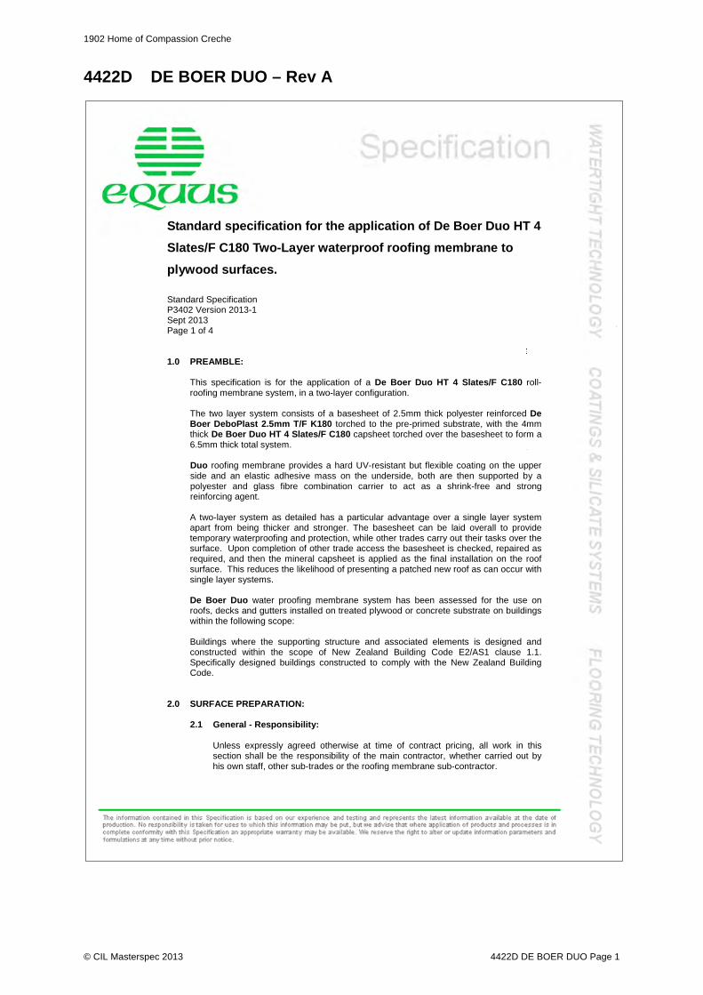
1902 Home of Compassion Creche
© CIL Masterspec 2013 4422D DE BOER DUO Page 1
4422D DE BOER DUO – Rev A
Standard specification for the application of De Boer Duo HT 4
Slates/F C180 Two-Layer waterproof roofing membrane to
plywood surfaces.
Standard Specification P3402 Version 2013-1 Sept 2013 Page 1 of 4 1.0 PREAMBLE:
This specification is for the application of a De Boer Duo HT 4 Slates/F C180 roll-roofing membrane system, in a two-layer configuration.
The two layer system consists of a basesheet of 2.5mm thick polyester reinforced De Boer DeboPlast 2.5mm T/F K180 torched to the pre-primed substrate, with the 4mm thick De Boer Duo HT 4 Slates/F C180 capsheet torched over the basesheet to form a 6.5mm thick total system. Duo roofing membrane provides a hard UV-resistant but flexible coating on the upper side and an elastic adhesive mass on the underside, both are then supported by a polyester and glass fibre combination carrier to act as a shrink-free and strong reinforcing agent.
A two-layer system as detailed has a particular advantage over a single layer system apart from being thicker and stronger. The basesheet can be laid overall to provide temporary waterproofing and protection, while other trades carry out their tasks over the surface. Upon completion of other trade access the basesheet is checked, repaired as required, and then the mineral capsheet is applied as the final installation on the roof surface. This reduces the likelihood of presenting a patched new roof as can occur with single layer systems. De Boer Duo water proofing membrane system has been assessed for the use on roofs, decks and gutters installed on treated plywood or concrete substrate on buildings within the following scope: Buildings where the supporting structure and associated elements is designed and constructed within the scope of New Zealand Building Code E2/AS1 clause 1.1. Specifically designed buildings constructed to comply with the New Zealand Building Code.
2.0 SURFACE PREPARATION:
2.1 General - Responsibility:
Unless expressly agreed otherwise at time of contract pricing, all work in this section shall be the responsibility of the main contractor, whether carried out by his own staff, other sub-trades or the roofing membrane sub-contractor.

1902 Home of Compassion Creche
© CIL Masterspec 2013 4422D DE BOER DUO Page 2
Page 2 of 4 P3402
2.2 Plywood:
.1 Plywood Grade and Thickness – Standard:
Plywood shall be minimum 17mm C-D structural plywood complying with AS/NZS 2269, with the sanded C face upwards. Plywood shall be treated to a minimum grade of H3 CCA treated. The moisture content prior to installation of the membrane system must not exceed 20%. LOSP treated plywood must not be used.
When applying to existing substrates and structures, they must be thoroughly inspected to ensure that they will not affect the performance of the membrane when applied. Closed-in construction spaces under membrane roofs and decks shall have adequate ventilation to prevent the accumulation of moisture under the membrane. There should be a minimum gap of 20 mm between the underside of the substrate and any insulation.
.2 Sheet Layout:
All sheets shall be laid out so as to maximise the use of whole sheets. All sheet joints shall be laid over framing members, in a staggered brick-bond pattern, running across the fall in the roof in accordance with E2/AS1.
.3 Sheet Spacing:
Sheets shall be laid tight butt jointed, i.e. with sheets butted but not cramped up, except where tongue and grooved joints are used in accordance with E2/AS1. In areas where condensation is likely, prepare sheet edges and underside with Chevaprime PBT.
.4 Sheet Fixing:
Plywood must be fixed in accordance with the Manufacturers instructions taking into account wind loading, frame spacing and ply thickness.
Screw-fix using countersunk stainless steel screws, gauge 10 and a length 3 times the thickness of the plywood in accordance with E2/AS1. All sheets should be laid in a bead of construction adhesive along all framing members. Where two-layer plywood surfaces are installed, the first layer may be power-nailed, but the second layer must be screw-fixed with all joints offset from the first layer. All fastener heads shall be recessed below the level of the sheet face. Screws shall be fixed at 150mm centres on sheet perimeter and 200mm through the body of the sheet.
Substrate framing must support the plywood at a minimum 400mm centres each way. All sheet joints must be fully supported. The substrate preparation may change to meet “specific design” requirements or engineering requirements. Confirmation will be required prior to application.

1902 Home of Compassion Creche
© CIL Masterspec 2013 4422D DE BOER DUO Page 3
Page 3 of 4 P3402
.5 Falls:
Seams should be constructed parallel with the fall, minimising ponding and flow restriction whenever possible. Roof, deck and gutter falls must be laid in accordance with E2/AS1 of the New Zealand Building Code.
.6 Corners
All leading edges of plywood shall be chamfered with a 5mm radius corner. All internal corners shall have min. 20x20 H3.2 treated timber fillets installed.
.7 Outlet Types:
Roof and deck outlets shall be installed as per clause 8.5.6 of E2 External Moisture of the New Zealand Building Code. Outlets shall be sized in accordance with E1 Surface Water of the New Zealand Building Code.
3.0 MEMBRANE APPLICATION:
3.1 Primer:
To the dried and prepared surface apply one (1) full coat of De Boer Duo Primer by brush/roller at a spreading rate of 5sqm/litre. Allow to dry for 4-24 hours depending upon prevailing weather conditions.
3.2 De Boer Deboplast 2.5mm T/F K180 Base Sheet:
Decide the most suitable direction to follow then unroll and align the first roll, cut to length as required, re-roll both ends to the middle then torch evenly overall to both basesheet and primer as this is unrolled. Ensure even heat application. Repeat in sequence with all rolls, maintaining laps of minimum 80mm. This lap automatically closes during the torching process. Offset end laps in adjacent runs.
3.3 De Boer HT4 C180 Slate Cap Sheet:
This is applied in the same manner as the basesheet. All laps shall be offset to prevent coincidence with the base-sheet laps. Following application of the cap sheet all joints are back sealed separately to ensure they are neatly and correctly closed.
If required, during the back-sealing operation, Duo Mineral Chip may be carefully scattered over the joint to provide a uniform appearance. This may also be carried out on areas of detailing to provide protection and uniformity of finish.
3.4 Detailing:
This shall include all outlets, pipe penetrations, gutter stop ends, parapet upstands, machinery plinths and anything above or below the roof surface. This is carried out before, during or in some cases after laying of the membrane depending on the detail type. All detailing shall be done in accordance with the manufacturer’s technical literature, Duo Application Manual current at the time of design, use, installation and maintenance.

1902 Home of Compassion Creche
© CIL Masterspec 2013 4422D DE BOER DUO Page 4
Page 4 of 4 P3402
3.5 Completion:
Upon completion of the system it shall be inspected and left for a short period (up to 2-3 weeks) to stabilise. At this time the entire installation shall be rechecked prior to any warranties being issued. Where possible, particularly on deck areas a pond test (24 hours) should be carried out.
Note: Any damage caused to the completed installation by other trades working
over the membrane after the initial inspection shall be the responsibility of the Main Contractor, who shall arrange appropriate protection as required.
4.0 MAINTENANCE AND WARRANTY:
4.1 Maintenance:
Equus Industries Limited recommends as normal maintenance, the finished roof areas are inspected every six months for cleaning and annually by a Certified Installer to ensure weather tightness and durability. Ensure the roof and all outlets are free of blockages and clear of unwanted debris, all associated flashings and cappings are sound, the general condition of the membrane, the membrane is free from surface moss, mould or lichen. Check all associated building elements that can impact on the durability of the membrane.
Higher risk areas such as sheet joints, substrate movement, edging, gutters, penetrations, corners, upstands, outlets and overflows require a thorough weather tight inspection on an annual basis.
4.2 Warranty:
The De Boer Duo Two-Layer Roofing System described in this specification may be warranted as to sheet integrity and to be waterproof for a period of up to twenty (20) years providing that:
.1 All work is carried out by a Certified Equus Applicator.
.2 De Boer Duo must be installed in accordance with the manufacturer’s technical literature, Duo Application Manual current at the time of design, use, installation and maintenance
.3 The Warranty is issued in conjunction with an appropriate Maintenance
Statement.
The period of warranty is determined by the situation of the installation; e.g. old or new, substrate, plain roof or open plant roof etc. The warranty period shall be determined for any contract in consultation with the Manufacturer or their representative.
The warranty is provided to the client by the Equus Applicator carrying out the work and is backed by the Manufacturer as to the fitness for the purpose of the materials supplied for the contract.
--oo0oo--
1902 Home of Compassion Creche
© CIL Masterspec 2013 SEP 4511 EXTERIOR TIMBER WINDOWS AND DOORS Page 1
4511 NEW EXTERIOR TIMBER WINDOWS AND DOORS – Rev A 1. GENERAL This section relates to the supply and installation of: - new exterior timber windows - exterior door frames and doors 1.1 RELATED WORK Refer to glazing sections for glazing Refer to painting sections for finishes Documents 1.2 DOCUMENTS Refer to the general section 1233 REFERENCED DOCUMENTS. The following
documents are specifically referred to in this section: NZBC E2/AS1 External moisture NZBC F4/AS1 Safety from falling AS/NZS 1170.2 Structural design actions - Wind loads NZS 3602 Timber and wood-based products for use in building NZS 3604 Timber-framed buildings NZS 4223.3 Glazing in buildings - Human impact safety requirements 1.3 ABBREVIATIONS AND TERMS SLS Serviceability limit state ULS Ultimate limit state Warranties 1.4 WARRANTY Provide warranty for: 5 years for materials Warrantor: Manufacturer Provide the warranty in the standard form in the general section 1237WA WARRANTY
AGREEMENT. Refer to the general section 1237 WARRANTIES for additional requirements. Performance - windows, exterior doors and frames 1.5 PERFORMANCE - WIND Construct windows, exterior doors and frames to withstand design wind pressures to NZS
3604. 1.6 PERFORMANCE - STRUCTURAL/WEATHER-TIGHTNESS The structural and weather-tight performance of the completed window installation, the
glazing and infill panels is the responsibility of the window manufacturer. 2. PRODUCTS Materials - general 2.1 EXTERIOR TIMBER Solid timber to NZS 3602 to profiles detailed. Moisture content 16% ex factory. Timber to be heart Totara to match original in size, profile and finish. 2.2 SASHES Solid timber to profiles detailed and complete with weather-seals and weather hoods as
necessary.

1902 Home of Compassion Creche
© CIL Masterspec 2013 SEP 4511 EXTERIOR TIMBER WINDOWS AND DOORS Page 2
2.3 EXTERIOR FACINGS AND SCRIBERS Treated H3.1 unless durable heart wood, to profiles detailed/scheduled. 2.4 GLASS Refer to glazing sections for glass type and thickness. To NZS 4223.3 Glazing in
buildings - Human impact safety requirements. 2.5 PANELS Refer to SELECTIONS for type. 2.6 INTERIOR TIMBER To NZS 3602. Moisture content 10-14%. Components 2.7 FLASHINGS GENERALLY Ensure that materials used for head, jamb and sill flashings are compatible with the
window frame materials and fixings and cladding materials. 2.8 WINDOW AND DOOR FURNITURE Refer to 5521 HARDWARE for type. 2.9 METAL FASTENINGS Galvanized steel or non-corrodible metal. 2.10 SCREWS Stainless steel or non-corrodible metal. Length sufficient to penetrate into the
background support up to the shank. Screws for fixing hinges, hardware or furniture to match the item being attached.
2.11 NAILS Length sufficient to penetrate into the background support at least half the nail length,
except if into radiata pine then three-fifths their length. 2.12 SASH STAYS Refer window schedule. Size and gauge to suit sash size and weight. 2.13 HINGES Size and gauge to carry door size and weight. Refer window schedule.for type, size and
material. 3. EXECUTION Conditions 3.1 GENERALLY Execution to include those methods, practices and processes contained in the unit
standards for the National Certificate in Carpentry and the National Certificate in Joinery (cabinetry, exterior joinery, and stairs).
3.2 DO NOT DELIVER Do not deliver any elements which cannot be unloaded immediately into suitable storage
conditions. 3.3 HANDLE Handle, unload and store elements without distortion and avoiding pre-finished surfaces
rubbing together, and contact with mud, moisture and other damaging materials. 3.4 PROTECT Protect all elements against damage to arrises and glazing beads. Store frames and
doors flat and away from moisture or direct sunlight. CHECK ALL OPENINGS

1902 Home of Compassion Creche
© CIL Masterspec 2013 SEP 4511 EXTERIOR TIMBER WINDOWS AND DOORS Page 3
Check all openings on site for size and standard of execution before installing window or door frames.
3.5 CONFIRM PREPARATION OF EXTERIOR WALL OPENINGS Confirm that exterior wall openings have been prepared ready for the installation of all
window and door frames. Do not proceed with the window and door installation until required preparatory work has been completed.
Required preparatory work includes the following: - wall plastering to openings finished ready for the installation of window and door frames. - installation of flashings (those which are required to be installed prior to frames). Assembly 3.6 FABRICATION GENERALLY Manufacture and fabricate frames, doors and sashes as detailed. Install hinges, stays
and running gear as scheduled. 3.7 FABRICATION SASHES Solid/finger-jointed timber to profiles detailed, complete with weather seals and weather
hoods as necessary and as detailed. 3.8 HINGES Fit hinges to doors to support the door size and weight 3 hinges Doors up to 2.2 metres 4 hinges Doors 2.2 - 2.6 metres Fit minimum 2 hinges per window sash 3.9 FACTORY FINISHING Before delivery to site: - Prime assemblies scheduled for paint finish with an alkyd wood primer. - Prime rebates and concealed faces of beads of assemblies scheduled for clear finish
with an alkyd wood primer. - Brace square and provide protection to assemblies during delivery to site. Where
factory glazed, indicate the presence of transparent glasses with whiting, tape or signs compatible with the glass type.
3.10 ON SITE FINISHING Before installation: - Prime assemblies scheduled for paint finish not already primed with an alkyd wood
primer. - Prime all rebates and concealed faces of beads of assemblies scheduled for clear finish
with an alkyd wood primer. - Re-prime/seal any subsequently cut edge. - Refer to painting section/s for finishing. Installation - frames 3.11 FIXING FRAMES Fit flashings to frame and framing as required. Fix and assemble frames rigidly in place,
plumb, level and true to line and face without distortion and with all opening sashes fully and easily operating. Fit facings, scribers, draught-stopping and sealants.
3.12 DISTORTION Do not distort frames when wedging or other packing, or when tightening fixings. If
necessary adjust packing and fixings to eliminate binding. Do not cut, plane or sand frames to remedy distortion.
3.13 FIXINGS Fix frames so that nail heads are covered by applied stops and beads. Punch all nail
heads below timber surfaces which will be visible in completed work. Ensure that at least one frame fixing is adjacent to each hanging point.

1902 Home of Compassion Creche
© CIL Masterspec 2013 SEP 4511 EXTERIOR TIMBER WINDOWS AND DOORS Page 4
3.14 EXTERNAL DOOR AND WINDOW FRAMES AND SASHES Fabricate as detailed. Jamb, head and sill liners as detailed. Wedge and rigidly fix in
place without distortion, plumb, and true to line and face, complete with full length sill tray, jamb and cap flashings and with all doors and sashes operating freely. Fit hardware.
3.15 INSTALL FLASHINGS Install flashings to heads, jambs and sills of frames as required by the window
manufacturer and as detailed on the drawings. Finish head flashings to match window finish.
Place all flashings so that the head flashing weathers the jamb flashings, which in turn
weathers over the upstand of the sill flashing. Ensure that sill flashings drain to the outside air.
Except where window/door frames are recessed, ensure that head flashings over-sail
jamb facings by 15mm at each end. Refer to 4821 FLASHINGS section for supply and installation.
3.16 COMPLETE AIR SEAL To NZBC E2/AS1:9.1.6 Air seals. Form an air-tight seal by means of proprietary
expanding foam, compressible foam strips, or sealants used with backing rods. Ensure that in combination with the internal linings a complete air seal is created.
3.17 FIX HARDWARE Fix all sash hardware and furniture as scheduled. 3.18 SAFETY STAYS Factory fit safety stays to all windows scheduled for safety stays and to all windows
where safety stays are required to comply with NZBC F4/AS1 4.0, Opening windows. Completion 3.19 ROUTINE CLEANING Carry out routine trade cleaning of this part of the work including periodic removal all
debris, unused and temporary materials and elements from the site. 3.20 DEFECTIVE OR DAMAGED WORK Repair damaged or marked elements. Replace damaged or marked elements where
repair is not possible or will not be acceptable. Adjust operation of equipment and moving parts not working correctly. Leave work to the standard required for following procedures.
3.21 PROTECTION Provide the following temporary protection of the finished work during the building
relocation: Plywood hordings over the exterior of all openings as indicated on the drawings Carpet wrapped around door jambs to full height Tape all glass across 4. SELECTIONS Refer to Schedule of Selections in drawing set.
1902 Home of Compassion Creche
© CIL Masterspec 2013 OCT 4512 EXISTING WINDOW REPAIRS Page 1
4512 REPAIRS TO EXISTING TIMBER WINDOWS 1 GENERAL
This section relates to the repair of existing timber joinery. All sound existing timber is to be retained in situ or put back to its original position, unless otherwise scheduled.
All timber fixings are to be retained as much as possible. Where new fixings are required for timber, they should be stainless steel.
1.1 RELATED WORK Refer to glazing sections for glass types. Refer to Painting sections for finishes. 1.2 ABBREVIATIONS AND TERMS SLS Serviceability limit state ULS Ultimate limit state WANZ Windows Association of Zealand
Refer general section 1232 INTERPRETATION & DEFINITIONS for abbreviations used throughout the specification.
Documents 1.3 DOCUMENTS
Refer to the general section 1233 REFERENCED DOCUMENTS.
The following documents are specifically referred to in this section:
NZBC E2/AS1 External moisture NZBC F4/AS1 Safety from falling NZBC H1/VM1 Energy efficiency NZBC H1/AS1 Energy efficiency AS/NZS 1170.2 Structural design actions - Wind loads NZS 3604 Timber-framed buildings NZS 4211 Performance of windows NZS 4223.3 Glazing in buildings - Human impact safety requirements BRANZ BU 337 Protecting Window Glass from Surface Damage NZS 3602 Timber and wood-based products for use in building NZS 3640 Chemical preservation of round and sawn timber AS/NZS 4347 Damp-proof courses and flashings
Documents listed above and cited in the clauses that follow are part of this specification. However, this specification takes precedence in the event of it being at variance with the cited document.
1.4 WARRANTY - WORKMANSHIP Provide a workmanship warranty: 2 years: For repairs -Provide this warranty in the standard form. Refer to the general section 1237 WARRANTIES for additional requirements.
Requirements 1.5 APPROVAL
Complete initial repairs, and obtain architect approval before continuing.
1.6 QUALIFICATIONS
Work to be carried out by tradespeople experienced, competent and familiar with the materials and techniques specified.
Performance 1.7 PERFORMANCE - WINDOWS AND DOORS
1902 Home of Compassion Creche
© CIL Masterspec 2013 OCT 4512 EXISTING WINDOW REPAIRS Page 2
The aim is that repaired joinery performance is not less than would be expected for an equivalent original window that had not needed repair for: - Deflection
- Structural - weathertightness -air tightness
1.8 PERFORMANCE - STRUCTURAL/WEATHER-TIGHTNESS The structural and weather-tight performance of the completed joinery, the glazing and
infill panels is the responsibility of the window repairer. 1.9 WIND - SPECIFIC DESIGN Design and evaluate the installation to the wind pressure parameters of AS/NZS 1170.2
Refer to SELECTIONS for ULS and SLS. Advise architect if installation is unlikely to achieve this.
2. Materials 2.1 TIMBER TO BE MECHANICALLY JOINTED TO EXISTING TIMBER New timber shall be the same species as the existing timber, be close grained, and be
100% heartwood. Timber adjacent to, but not joined to existing timber. To be pinus radiata per timber framing section
2.2 GLASS Refer to the glazing section for glass types and installation. Flashings To NZBC E2/AS1, 9.1.10 Windows and Doors. 2.3 METAL FLASHINGS Evaluate any existing flashings and replace as required with material, grade and colour
as agreed with architect. Ensure that materials used for head, jamb and sill flashings are compatible with the window frame materials and fixings and cladding materials.
2.4 DPC Polyethylene film to AS/NZS2904 and embossed on both sides. Thickness 500 microns
minimum manufactured for use as a damp-proof course and concealed flashings to doors and windows.
Fixings 2.5 NAILS Type to NZS 3604, section 4: Durability (note that this is a sea spray zone, and 304
stainless steel is required), and of the size and number for each particular types of joint as laid down in the nailing schedules of NZS 3604, sections 6-10.
2.6 BOLTS AND SCREWS Of engineering and/or coach type complete with washers, to the requirements of NZS
3604, section 4: Durability, and of the number and form required for each particular junction to NZS 3604, sections 6-10. In addition, where fixing into treated timber than may be damp (i.e. piles, bearer), use a powder-coated bolt. No self tapping screws.
2.7 TIMBER CONNECTORS, BRACING STRAPS Supply as required for stiffening to existing joinery. Stainless steel. Powder actuated
fasteners Not permitted 2.8 HARDWARE AND FURNITURE Hinges, stays, catches, fasteners, latches, locks and furniture per window schedule.
manufacturer. Refer to SELECTIONS for type and finish. Key alike all lockable window hardware able to be keyed alike.
Sealants

1902 Home of Compassion Creche
© CIL Masterspec 2013 OCT 4512 EXISTING WINDOW REPAIRS Page 3
2.9 WEATHERING/INSTALLATION SEALANT Building sealant used in accordance with manufacturer's instructions for weather sealing
frames to the cladding where shown in details. 2.10 FOAM TAPE Foam tape to NZBC E2/AS1, 9.1.10.7 Closed cell foam tape. If required in details. Finishes 2.11 PAINT Refer to SELECTIONS for systems. 3. EXECUTION Conditions – generally 3.1 DIMENSIONS All timber sizes for replacement or repair work shall match the member being removed 3.2 GENERAL PRINCIPLES FOR GLUES AND FIXING A principle of all connections in materials is that the connecting material should be
weaker than the material it is joining. This will allow the stresses to be accommodated within the joint, which should be designed to take them, rather than transferring stresses to the body of the material and causing it to fail. Thus Epoxy is only a good solution where it is used to reinstate the damaged portion of a single structural element.
Where two structural elements join at a corner, e.g. a head and jamb lining of a door; the stile and rail of a door leaf; stile and rail of a window sash; traditional glue such as PVA should be employed, which will allow future repairs.
Glue nails and self-tapping screws should be avoided for the same reason. Should these elements require repair in the future, their removal will almost certainly destroy them. Nails on the other hand are easily withdrawn with minimal damage.
3.3 DO NOT DELIVER Do not deliver to site any elements which cannot be unloaded immediately into suitable
conditions of storage. 3.4 AVOID DISTORTION Avoid distortion of elements during transit, storage and handling. 3.5 PREVENT DAMAGE Prevent prefinished surfaces rubbing together, and contact with mud, plaits er and
cement. Keep paper and cardboard wrappings dry. 3.6 PROTECTIVE COVERINGS Retain protective coverings and coatings to BRANZ BU 337 and keep in place during the
fixing process. Provide protective coverings and coatings where required to prevent marking of surfaces visible in the completed work and to protect aluminium joinery from following trades. Remove protection on completion.
3.7 ADDITIONAL PROTECTION Supply and fix additional protection as necessary to prevent marking of surfaces which
will be visible on completed work. Conditions - fixings and fastenings 3.8 SUPPLY OF FIXINGS Ensure fixings and fastenings exposed to the weather are of aluminium, or Type 316
stainless steel or if not exposed to the weather may they be hot-dip galvanized steel with a coating weight of 610 g/m² complying with AS/NZS 4680.
3.9 FIXING To NZBC E2/AS1, 9.1.10.8, Where required by details, or off site . Ensure fixings do not penetrate metal flashings.
Install packers between reveals and framing at fixing points, except at the head.

1902 Home of Compassion Creche
© CIL Masterspec 2013 OCT 4512 EXISTING WINDOW REPAIRS Page 4
3.10 PROTECT Protect all new and existing timber joinery against damage and from inclement weather.
Ensure that any variation in moisture content is kept to a minimum, before and after erection and before enclosure. Where entire window assemblies are removed, they shall be worked on and stored in an enclosed space.
3.11 STORE All windows and doors removed from the wall opening shall be stored flat, and filleted.
Execution to comply with NZS 3604, except as varied in this specification. 3.12 EXECUTION Execution to include those methods, practices and processes contained in the unit
standards for the National Certificate in Carpentry and the National Certificate in Joinery (cabinetry, exterior joinery, stairs).
3.13 FRAMING MOISTURE CONTENT Timber for repairs shall be air seasoned in an enclosed environment for at least two
years. At use:16% EMC maximum. 3.14 TOLERANCES. Profile new timbers to match exactly the existing. Repaired sashes, or frames should be
square, except where required to be adjusted to suit the opening Assembly 3.15 REPAIR Repair frames as detailed and agreed on site. Install glazing, hinges, stays and running
gear as scheduled. Provide temporary bracing and protection. 3.16 HARDWARE GENERALLY Fit all required and scheduled hardware. Account for all keys and deliver separately to the
site manager. 3.17 SAFETY STAYS Fit safety stays to all windows scheduled for safety stays and to all windows where safety
stays are required to comply with NZBC F4/AS1 4.0, Opening windows. Installation - windows and doors (where required) 3.18 CORROSION PROTECTION Before fixing, apply suitable barriers of bituminous coatings, stops or underlays between
dissimilar metals in contact, or in contact with concrete. 3.19 CONFIRM PREPARATION OF EXTERIOR WALL OPENINGS Confirm that exterior wall openings have been prepared ready for the installation of all
window and door frames. Do not proceed with the window and door installation until required preparatory work has been completed.
3.20 INSTALLATION Fix to comply with the drawings drawings and installation details including flashings and
bedding compounds, pointing sealants and weathering sealants. 3.21 INSTALL FLASHINGS Install flashings to heads, jambs and sills of frames as detailed on the drawings. Place all flashings so that the head flashing weathers the jamb flashings, which in turn
weathers over the upstand of the sill flashing. Ensure that sill flashings drain to the outside air.
Except where window/door frames are recessed, ensure that head flashings over-sail unit by 20mm minimum plus any jamb scriber width at each end. Ensure that flashings are fully detailed, preferably as 3-dimensional diagrams, to ensure that they are fabricated and installed in a manner that will avoid the ingress of moisture.
3.21 COMPLETE AIR SEAL

1902 Home of Compassion Creche
© CIL Masterspec 2013 OCT 4512 EXISTING WINDOW REPAIRS Page 5
To NZBC E2/AS1:9.1.6 Air seals. Form an air-tight seal by means of a proprietary expanding foam or sealants used with
backing rods, applied between the window / door reveal and structural framing to a depth of 10 - 20mm, to provide a continuous air tight seal to the perimeter of the window or door. Formation of an air seal around all penetrations in the building envelope will greatly reduce the likelihood of water ingress occurring; especially when employed in combination with well designed joinery frames and appropriately detailed and installed flashings.
3.22 FIX HARDWARE Fix all sash and door hardware and furniture as scheduled. Application —Joinery 3.23 REPAIR TECHNIQUES Timber failures in windows are identified in the report. Always ensure decayed timber is
completely removed, as any remaining rot ill continue to decay behind the newly indented timber. Any timber spliced into sash or frame shall be pinned and glued into place. Cuts made in old wood should, wherever possible, be angled to direct moisture away from the site of the repair. Timber for splicing shall be radially cut with the radial cut inserted parallel to the widest dimension of the repair object. Metal reinforcing/stiffening straps may be allowed in specific cases – refer to architect.
3.24 SETOUT Set timbers true to required lines and levels with mitres, butt joints, laps and housings cut
accurately to provide full and even contact over the whole of the bearing surface. 1.5.4 5.4 Selections Wood working glue shall be waterproof. Nails, screws etc to be stainless
Application - jointing and sealing 3.25 PREPARE JOINTS Ensure joints are dry. Remove loose material, dust and grease. Prepare joints in
accordance with the sealant manufacturer's requirements, using required solvents and primers where necessary. Mask adjoining surfaces which would be difficult to clean if smeared with sealant.
3.26 BACK UP When using back-up materials do not reduce depth of joint for sealant to less than the
minimum required by the manufacturer of the sealant. Insert polyethylene rod or tape back-up behind joints being pointed with sealant.
3.27 SEALANT FINISH Tool sealant to form a smooth fillet with a profile and dimensions required by the sealant
manufacturer. Remove excess sealant from adjoining surfaces, using the cleaning materials nominated by the sealant manufacturer and leave clean.
Completion - cleaning. 3.28 REMOVE TRADE DEBRIS Remove trade debris by appropriate means basis as completed and again before any
work is covered up by others. Arrange for general removal. 3.29 TRADE CLEAN Trade clean window frames, operable windows and doors, glass and other related
surfaces inside and out at the time of installation to remove marks, dust and dirt, to enable a visual inspection of all surfaces.
Completion. 3.30 PROTECTIVE COVERINGS Provide protective coverings and coatings where required to prevent marking of surfaces
visible in the completed work and to protect joinery from following trades, especially internal and external plastering and painting.
3.31 SAFETY
1902 Home of Compassion Creche
© CIL Masterspec 2013 OCT 4512 EXISTING WINDOW REPAIRS Page 6
Indicate the presence of transparent glasses for the remainder of the contract period, with whiting, tape or signs compatible with the glass type. Indicators other than whiting must not be applied to the glass surface. Masking tape must not be used for this purpose..
This clause does not refer to the NZS 4223.3 requirement for "manifestations" required for post-construction building use where a glass door or panel could be mistaken for an unimpeded path of travel.
3.32 REMOVE At the appropriate stage of the project, remove safety indicators and protective coverings
and wipe down all joinery thoroughly. 3.33 MANIFESTATIONS Apply manifestations to comply with NZS 4223.3, 303.1 Manifestations. Note NZS 4223.3, sets minimum standards for delineating glass "capable of being
mistaken for an unimpeded path of travel". While this issue is best resolved in the basic design of the installation, in some cases applied signs, decals, sandblasting or attached rails are necessary. Consider and specify accordingly.
4. SELECTIONS Refer to Schedule

1902 Home of Compassion Creche
© CIL Masterspec 2013 JAN 4611 GLAZING EXTERIOR Page 1
4611 GLAZING EXTERIOR 1. GENERAL This section relates to the supply and fixing of glass products for external joinery in
complex residential and commercial buildings, including: - window and doors 1.1 RELATED WORK Refer to ~ for ~ 1.2 ABBREVIATIONS AND DEFINITIONS Refer to the general section 1232 INTERPRETATION & DEFINITIONS for abbreviations
and definitions used throughout the specification. The following abbreviations apply specifically to this section: PVB Polyvinyl Butyral CIP Cast in place Documents 1.3 DOCUMENTS Refer to the general section 1233 REFERENCED DOCUMENTS. The following
documents are specifically referred to in this section: NZBC B1/AS1 Structure NZBC F2/AS1 Hazardous building materials NZBC F4/AS1 Safety from falling NZBC H1/AS1 Energy Efficiency NZS 3604 Timber-framed buildings NZS 4211 Performance of windows NZS 4218 Thermal insulation - Housing and Small Buildings NZS 4223.1 Glazing in buildings - Glass selection and glazing NZS 4223.3 Glazing in buildings - Human impact safety requirements NZS 4223.4 Glazing in buildings - Wind, dead, snow and live action NZS 4223.Supp1 Glazing in buildings - Supplement 1 to NZS 4223.1:2008 and NZS
4223.4:2008 NZS 4243.1 Energy Efficiency - Large Buildings - Building thermal envelope AS/NZS 2208 Safety glazing materials in buildings AS/NZS 4666 Insulating glass units BRANZ BU 337 Protecting window glass from damage Warranties 1.4 MANUFACTURERS WARRANTY Warrant glass under normal environmental and use conditions against failure of materials Refer to the general section for the required form of 1237WA WARRANTY AGREEMENT
and details of when completed warranty must be submitted. 2. PRODUCTS Materials 2.1 CLEAR FLOAT GLASS Clear ordinary annealed transparent float glass for general window glazing. Thickness to
NZS 4223.1 and NZS 4223. Supp 1. Components, general

1902 Home of Compassion Creche
© CIL Masterspec 2013 JAN 4611 GLAZING EXTERIOR Page 2
2.2 JOINTING, PUTTY AND SEALING MATERIALS Ensure jointing, putty and sealing materials are compatible with glass substrates.
Confirm compatibility with laminated glass, IGU's and coatings. Components, timber glazing 2.3 PUTTY, TIMBER FRAME Linseed oil base glazing putty. 2.4 SPRIGS Diamond metal pieces to retain glass in timber sashes and frames. 3. EXECUTION Conditions 3.1 GENERAL REQUIREMENTS To NZS 4223.1, NZS 4223.3, NZS 4223.4 and NZBC B1/AS1, 7.0 Glazing. All external
glazing to be wind and watertight on completion. 3.2 DELIVERY Keep glass dry and clean during delivery and bring on to site when ready to glaze directly
into place. Comply also with the storage requirements set out in BRANZ BU 337. 3.3 GLASS CONDITION All glass to have undamaged edges and surfaces. 3.4 GLASS THICKNESS If not specifically stated in the glazing schedule determine the minimum thickness of glass
for each sheet as required by NZS 4223.1, NZS 4223.3, NZS 4223.4, and NZS 4223.4 Supp 1.
Determine the final glass thickness based on whether wind loading or human impact considerations govern.
3.5 REBATE DIMENSIONS Provide rebates for glazing to the widths and depths necessary for each situation
including minimum glass edge cover to NZS 4223.1, Section 4 Glazing. Assembly 3.6 WORKING OF GLASS All working of glass as required in NZS 4223.1. 3.7 EDGE WORK AND BEVELLING Edgework other than a clean cut. Refer to SELECTIONS/drawings for type. 3.8 SURFACE TREATMENT Refer to SELECTIONS/drawings for finish. Application - timber glazing 3.9 PREPARE REBATES Ensure all rebates and grooves are clean, dry and unobstructed at time of priming,
sealing and glazing. 3.10 PREPARE TIMBER SURROUNDS Ensure that all rebates have been primed with a primer suitable for this purpose and
applied to the requirements of the painting section/s. 3.11 PREPARE TIMBER BEADS Before fixing ensure that timber beads are sealed and painted to match the timber
surround.

1902 Home of Compassion Creche
© CIL Masterspec 2013 JAN 4611 GLAZING EXTERIOR Page 3
3.12 LOCATE BLOCKS Centralise the glass in the rebate opening using setting, location and spacer blocks as
required in NZS 4223.1, Section 4 Glazing, to prevent movement of glass in the rebate, and cushion the effect of wind loading on the sealing system.
3.13 INSTALL PUTTY FRONTING Back putty to give a bedding of not less than 1 to 2mm between the glass and the back of
the rebate when the glass has been pressed back. Strip off squeezed out putty at a positive angle. Fix glass to wooden surrounds with diamond points or sprigs at maximum 460mm centres. Fix glass to metal surrounds with spring clips or pins provided by the sash manufacturers. Apply putty to the face to form a triangular fillet stopping 1-2mm below sight line. Finish putty smooth and true to line and face and with a light brushing.
Leave all windows and doors closed until putty has set sufficiently to prevent glass
displacement. Prime putty fronting once surface has skinned - normally within 10 - 15 days of
completion of glazing, but this can be reduced with special XHP putty. Finishing 3.14 SAFETY Indicate the presence of transparent glass for the remainder of the construction period,
with whiting, tape or signs compatible with the glass type. Indicators other than whiting must not be applied to the glass surface.
3.15 MANIFESTATIONS To NZS 4223.3, clause 303.1 Manifestation (making glass visible). Completion 3.16 TRADE CLEAN Clean off or remove safety indicators at completion of the building. 3.17 REPLACE Replace damaged, cracked or marked glass. 3.18 LEAVE Leave work to the standard required by following procedures. 3.19 REMOVE Remove debris, unused materials and elements from the site. 4. SELECTIONS Refer to Schedule of Selections in drawing set.

1902 Home of Compassion Creche
© CIL Masterspec 2013 FEB 4711A AUTEX GREENSTUF® THERMAL INSULATION Page 1
4711A AUTEX GREENSTUF® THERMAL INSULATION – Rev A 1. GENERAL This section relates to Autex GreenStuf® polyester fibre insulation installed, laid, hung or
fitted as thermal insulation. 1.1 RELATED WORK Refer to ~ for ~ 1.2 ABBREVIATIONS AND DEFINITIONS Refer to the general section 1232 INTERPRETATION & DEFINITIONS for abbreviations
and definitions used throughout the specification. The following abbreviations apply specifically to this section: BIB Building Insulation Blanket Documents 1.3 DOCUMENTS Refer to the general section 1233 REFERENCED DOCUMENTS. The following
documents are specifically referred to in this section: NZBC E2 External moisture NZBC H1/AS1 Energy efficiency AS/NZS 3000 Electrical installations NZS 4218:2004 Energy Efficiency - Small building envelope NZS 4220 Code of practice for energy conservation in non-residential buildings NZS 4243.1 Energy Efficiency - Large buildings - Building thermal envelope NZS 4246 Energy Efficiency - Installing insulation in residential buildings AS/NZS 4534 Zinc and zinc/aluminium-alloy coatings on steel wire AS/NZS 60598.2.2 Luminaires- Particular Requirements - Recessed luminaires AS/NZS 60695.11.5 Fire hazard testing - Test flames - Needle-flame test
method - Apparatus, conformity test arrangement and guidance AS/NZS ISO 9001 Quality management systems - requirements 1.4 MANUFACTURER/SUPPLIER DOCUMENTS Autex Insulation documents related to this section are: Autex Insulation Product Manual, including: Data sheet GreenStuf® Thermal Insulation - Pad Form Data sheet GreenStuf® Underfloor Installation Instructions - GreenStuf® Thermal Insulation Installation Instructions - GreenStuf® Underfloor Insulation Autex Insulation Warranty Certificate BRANZ Appraisal 380 - Autex Greenstuf® Polyester Thermal Insulation BRANZ Appraisal 734 GreenStuf® Underfloor Insulation Environmental Choice NZ (Licence No. 2508037) Autex GreenStuf® polyester thermal
(resistive-type) insulation Manufacturer/supplier contact details Company: Autex Industries Limited Web: www.autex.co.nz Telephone: 0800 428 839 Autex Insulation documents are also available on EBOSS Web: www.eboss.co.nz Warranties 1.5 WARRANTY - MANUFACTURER/SUPPLIER Provide a material manufacturer/supplier warranty: - For Autex polyester thermal and acoustic insulation products. - Provide this warranty on the Autex Insulation Certificate of Warranty standard form.
1902 Home of Compassion Creche
© CIL Masterspec 2013 FEB 4711A AUTEX GREENSTUF® THERMAL INSULATION Page 2
Requirements 1.6 QUALIFICATIONS Work to be carried out by tradesmen experienced, competent and familiar with Autex
Insulation materials and techniques specified. 1.7 NO SUBSTITUTIONS This work section relates to NZBC compliant systems and under the building consent
process substitutions are not permitted to any specified insulation, associated products, components or accessories.
Autex GreenStuf® products have been selected on specific performance criteria and their
reduced environmental impact. Substitution of specified insulation materials will not be accepted.
2. PRODUCTS Materials 2.1 POLYESTER FIBRE THERMAL INSULATING PADS Autex GreenStuf® Pad Form- 100% polyester fibres thermally bonded to form a
rectangular insulation pad. Manufactured in NZ under AS/NZS ISO 9001 and ISO 14001 quality and environmental management systems. Refer to SELECTIONS for details.
NOTE: All GreenStuf® Polyester insulation is compliant with AS/NZS 60695.11.5 and can safely be installed abutted to downlights classified CA 80, CA 135 and can be safely installed covering downlights classified IC and IC-F.
2.2 POLYESTER FIBRE THERMAL UNDERFLOOR INSULATION Autex GreenStuf® Underfloor- 100% polyester fibres thermally bonded to form a flexible
insulation roll for insulating the underside of exposed joist floors. Manufactured in NZ under AS/NZS ISO 9001 and ISO 14001 quality and environmental management systems. Refer to SELECTIONS for details.
Components 2.3 STAPLES / GUN STAPLER Gun stapler and staples (standard or stainless steel as appropriate) for fixing GreenStuf®
Masonry Wall Blanket and GreenStuf® Underfloor in place. 3. EXECUTION Conditions 3.1 STORAGE Accept materials undamaged and dry and store in a location that protects them from the
weather and damage. Avoid distortion, stretching, puncturing and damage to insulation and packaging. Do not use damaged materials.
3.2 HANDLING Avoid distortion of rectangular pad form. Maintain full thickness of the insulation unless
compression is an installation system requirement. 3.3 INSPECTION Before starting installation of Autex GreenStuf® blankets, pads and rolls, check that the
location and framing are free from moisture, that the cavities are not interconnected and that mesh, underlays and vapour barriers are in place.
Application 3.4 INSTALL INSULATION - GENERAL Lay, install, fit and fix to NZBC H1/AS1: Energy efficiency, 2.0 Building thermal envelope,
and to manufacturer's requirements. Install in housing to NZS 4218 and NZS 4246.

1902 Home of Compassion Creche
© CIL Masterspec 2013 FEB 4711A AUTEX GREENSTUF® THERMAL INSULATION Page 3
Install in large buildings to NZS 4243.1 and NZS 4220. Allow insulation to re-loft/relax prior to installation. Do not cover vents. Allow a clear gap around metal flues as recommended by the fireplace manufacturer. Lift up electrical wires, lighting transformers/controllers and lay the insulation underneath.
3.5 CHECK FOILS Ensure foils are dry, clean, bright, undamaged and free of debris before installing
insulation. 3.6 FIT POLYESTER FIBRE THERMAL INSULATION PADS Friction fit GreenStuf®insulation pads in place to completely fill the whole of the cavities.
Slightly oversize length for friction fit and tear by hand across pad and fill cavity. Tear to smaller pieces for smaller spaces and around penetrations. Leave no gaps and maintain full thickness over the whole of the installation. Do not cover vents and cut around metal flues to the safety requirement of the fireplace manufacturer. Fix in place with plastic tape as necessary to hold the insulation until the wall and or ceiling linings are in place.
Refer to GreenStuf® Pads and Roll Form installation instructions. 3.7 FIT POLYESTER FIBRE THERMAL UNDERFLOOR INSULATION Friction fit GreenStuf® Underfloorinsulation rolls between the floor joists to completely fill
the space between each. Slightly oversize length for friction fit and tear by hand across the width of the roll. Tear to smaller pieces for smaller spaces and around penetrations. Leave no gaps and maintain full thickness over the whole of the installation. Insulation should be stapled into place using a staple gun to each side of the joist. In coastal areas use stainless steel staples to avoid corrosion.
Refer to GreenStuf® Underfloor installation instructions. Completion 3.8 CLEAN UP Clean up as the work proceeds so no spare off-cuts or any other matter or item remain
behind claddings or linings. 3.9 LEAVE Leave work to the standard required by following procedures. 3.10 REMOVE Remove debris, unused materials and elements from the site. 4. SELECTIONS Refer to Schedule of Selections in drawing set.

1902 Home of Compassion Creche
© CIL Masterspec 2013 4811S SIKA SEALANTS Page 1
4811S SIKA SEALANTS – Rev A 1. GENERAL This section relates to the selection of sealants and application methods for sealants
nominated in other work sections. Related work 1.1 RELATED SECTIONS Refer to 4224 TIMBER EXTERIOR TRIM Refer to 4511 EXTERIOR TIMBER WINDOWS AND DOORS Documents 1.2 DOCUMENTS Documents referred to in this section are: ISO11600 Building construction - Jointing products - Classification and
requirements for sealants Documents listed above and cited in the clauses that follow are part of this specification.
However, this specification takes precedence in the event of it being at variance with the cited document.
1.3 MANUFACTURER'S DOCUMENTS Sika (NZ) Ltd product data sheets relating to work in this section are: Sika Primer Table Sikaflex / Sikabond. Version no: 02/08
Sikaflex® AT-Facade. Version no: 03/08 Sikaflex® Construction. Version no: 05/11 Sikasil® Roofing and Plumbing. Version no: 06/10 Sikasil ® NG. Version no: 17/08/08 Sika® Primer MB Version no 08.05
Independent VOC test certificates for quantity of VOC in grams per litre in accordance
with SCAQMD Rule 1168 to Green Star Office design V2 IEQ-13/ IEQ-03 Copies of the above literature are available from Sika (NZ) Ltd Web: www.sika.co.nz Email: [email protected] Telephone: 0800 SIKA NZ, 0800 745 269 Facsimile: 0800 SIKA FAX, 0800 745 232 1.4 ABBREVIATIONS AND TERMS The following abbreviations and terms are used throughout this part of the specification: VOC Volatile Organic Compound Requirements 1.5 SEALANT SELECTION Refer to the Sika (NZ) Ltd current Technical Data Sheet before commencing sealant
installation. Ensure that the correct sealant has been selected for the intended application and substrates. Check that the joint design allows for movement and or substrate thermal expansion and contraction, and is within the sealants range of service.
1.6 SAMPLE JOINT Produce a sample joint for substrates or coatings not detailed in Sika (NZ) Ltd current
Technical Data Sheet. Upon full cure of the selected Sika sealant the test sample is to be used to assess sealant adhesion and compatibility with the substrate or coating. Following review and confirmation that work may proceed, the sample joint becomes the quality control standard for subsequent work of each type. Sample joints may be retained as part of the completed work.

1902 Home of Compassion Creche
© CIL Masterspec 2013 4811S SIKA SEALANTS Page 2
1.7 QUALIFICATIONS Sealant work, including preparation, to be carried out by competent and experienced
sealant applicators, approved by Sika. Provide evidence of technical competence and experience for review before commencing work.
1.8 MANUFACTURER'S TECHNICAL SERVICES Sika (NZ) Ltd provides local testing and research and development assistance for non
standard applications. Use the research and development, and the technical information provided by Sika throughout the design, development, prototype testing and installation stages of sealant work.
Warranties 1.9 WARRANTY - MANUFACTURER/SUPPLIER Provide Sika (NZ) Ltd warranty for: 10 years: For material - Provide the warranty in the Sika form. - Commence the warranty from the date of practical completion of the contract works. - Sika (NZ) Ltd will warrant that Sika sealant products will perform in accordance with the
information stated in Sika (NZ) Ltd current Technical Data Sheets. - Refer to Sika (NZ) Ltd for further information on warranty. 2. PRODUCTS Materials Silicone sealants 2.1 SIKASIL® ROOFING AND PLUMBING Sikasil® Roofing and Plumbing, a one component Alcoxy (neutral curing) silicone sealant
suitable for roofing and plumbing applications. 2.2 SIKASIL® NG Sikasil ® NG, a one part fast cure neutral silicone sealant to provide a permanent
watertight seal to various substrates including plastics, ceramics and some powder coated surfaces.
3. EXECUTION Conditions 3.1 COMPATIBILITY Ensure compatibility by using only Sika branded sealants with Sika supplied joint fillers,
primers, backing rods, bond breaker tape and cleaning solutions. 3.2 NON SLUMP SEALANTS Use only thixotropic sealants capable of supporting their own weight (non slump) in
vertical applications. 3.3 SELF LEVELLING SEALANTS Use only self levelling sealants in contained horizontal applications. 3.4 SUBSTRATE STAINING Note that some silicon sealants can cause silicon oil staining on porous substrates such
as concrete and masonry. 3.5 SEALANT PAINTABILITY Ensure that a paintable sealant is selected when the sealant joint requires painting.
NOTE: This excludes silicon based sealants which are not paintable. 3.6 COLOURS

1902 Home of Compassion Creche
© CIL Masterspec 2013 4811S SIKA SEALANTS Page 3
Refer to SELECTIONS for colour option/s. Where colour is not specified, choose sealant colours from the Sika standard/special colour ranges.
3.7 VISIT THE SITE Arrange for the Sika representative to visit the site to examine the site conditions, to
inspect the surfaces and joints and to discuss the installation procedures, before any sealing work proceeds.
Preparatory work 3.8 ENSURE Ensure that joints to receive sealants are suitable for the proposed application. Ensure
that surfaces are sound, dry, free from dust, dirt, scale, laitance, corrosion or other loose material, oil, grease, paint, release agents or other contaminants which may affect the bond, or the performance of the sealing material.
Ensure that joints and spaces receiving sealant are within the specified width to depth
ratio in accordance with Sika sealant product data sheet. Ensure that the joint design allows for movement and/or substrate thermal expansion and contraction that are within the sealants range of service.
3.9 TEST SUBSTRATES Test substrates for indications of staining or poor adhesion. If poor adhesion is evident
from initial tests, consult Sika about the application of a suitable primer. Only use combinations of sealants and substrates for which favourable adhesion and compatibility have been confirmed.
Do not apply sealant to concrete or concrete block until concrete and/or mortar has cured. 3.10 CLEAN JOINTS Clean joints as detailed in application instructions contained in Sika (NZ) Ltd product data
sheet to achieve acceptable joint surfaces for the application of sealant. Protect adjacent surfaces from abrasion or other damage.
3.11 CLEAN METAL SURFACES Clean metal surfaces with approved Sika (NZ) Ltd cleaners to remove any grease
deposits. 3.12 GRIND CONCRETE SURFACES Grind concrete surfaces to remove concrete laitance and other surface contaminates
prior to applying Sika Primers 3.13 MASK Mask adjacent surfaces alongside joints to prevent contamination. Mask off any surfaces
which would be difficult to clean if smeared with sealant, or where excess sealant could not be neatly trimmed off or removed.
3.14 VENTILATION Ensure adequate ventilation for sealant applicators during the preparation and application
of sealant work. Application 3.15 FINAL PREPARATION Prepare joints in accordance with approved Sika (NZ) Ltd cleaning methods. 3.16 BACKING Insert Sika PEF backing rod or bond breaker tape to avoid three sided adhesion. Sika
PEF backing rod diameter is be 25% larger than the gap size. Use only blunt instruments to install backing rods to avoid puncturing or damage. Do not twist rods when installing. When using backup material do not leave gaps and do not reduce the depth of the sealant joint to less than the minimum required by Sika.

1902 Home of Compassion Creche
© CIL Masterspec 2013 4811S SIKA SEALANTS Page 4
3.17 PRIMING Use Sika supplied/recommended primers. Allow to cure for Sika recommended time
(minimum and maximum). Refer to Sika for instructions if maximum cure time is exceeded before sealant is applied. Do not contaminate bond breakers with primer.
Allow primer to dry as recommended by the manufacturer. Do not prime more than can
be completed in one day. Prevent contamination of the primed surfaces prior to applying sealant.
3.18 JOINT FILLING Fill joint cavity with sealant in accordance with Sika requirements and quality control
programmes. Use a pressure gun with a nozzle cut to suit the required joint width. Ensure sealant is deposited in a uniform, continuous bead, without gaps or air pockets and with clean, neat edges.
3.19 TOOLING Tool sealant to form a smooth, flat bead, or a smooth convex fillet, with a profile as
required by Sika. Complete tooling before the sealant surface starts to form a skin. 3.20 FINISHING Remove masking immediately after tooling and before sealant surface starts to skin.
Remove excess sealant from adjoining surfaces before the sealant has set, using the cleaning materials and methods required by Sika, leaving surfaces clean and the sealant runs undamaged.
3.21 SURROUNDING WORK Leave surrounding surfaces in a neat, clean condition with no evidence of spill over. Completion 3.22 CLEAN UP Clean up as the work proceeds. 3.23 LEAVE Leave work to the standard required by following procedures. 3.24 REMOVE Remove masking tape, used packaging and waste products from the site. 4. SELECTIONS Refer to Schedule of Selections in drawing set.

1902 Home of Compassion Creche
© CIL Masterspec 2013 JUL 4821 FLASHINGS Page 1
4821 FLASHINGS – Rev A 1. GENERAL This section relates to the fabrication and installation of flashing systems not forming part
of a proprietary system. 1.1 RELATED WORK Refer to 4311 PROFILED METAL ROOFING Refer to 4311C CALDER STEWART EUROTRAY Documents 1.2 DOCUMENTS Refer to the general section 1233 REFERENCED DOCUMENTS. The following
documents are specifically referred to in this section: NZBC B2/AS1 Durability NZBC E2/AS1 External moisture AS/NZS 2728 Prefinished/prepainted sheet metal products for interior/exterior
building applications - Performance requirements AS 3566 Self-drilling screws for the building and construction industries -
General requirements and mechanical properties NZS 3604 Timber-framed buildings NZMRM - CoP NZ Metal roof and wall cladding - Code of practice (CoP) Requirements 1.3 QUALIFICATIONS Work to be carried out by tradesmen experienced, competent and familiar with the
materials and techniques specified. 1.4 VERIFY DIMENSIONS Verify dimensions against site measurements prior to fabrication. Standards of performance 1.5 DURABILITY REQUIREMENTS Design and install the flashings appropriate for the durability applications in accordance
with NZBC B2/AS1. The Building Code B2, 3.2 requires that all hidden elements have at least the same durability as that of the element that covers it. Refer to NZBC B2/AS1 Table 1: Durability Requirements of Nominated Building Elements and NZBC E2/AS1 Table 20 Material selection.
1.6 COMPATIBILITY REQUIREMENTS Each flashing material shall be selected in accordance with NZBC E2/AS1 Table 20 to
minimise corrosion. Refer to either NZS 3604 Clause 4.2 or AS/NZS 2728 for the relevant exposure conditions. For compatibility of materials in contact and subject to run-off, refer to NZBC E2/AS1 table 21 and NZBC E2/AS1 table 22.
1.7 DESIGN For flashings where there are no specific details or drawings, provide a full size mock up
of the flashing to integrate components into the weathertight system. Co-ordinate with the trades affected by the installation.
2. PRODUCTS 2.1 FLASHING MATERIALS Acceptable materials for flashings are described in NZBC E2/AS1, 4.0. Material, grade
and colour as detailed and scheduled. Ensure that materials used for flashings are compatible with the building and cladding materials and their fixings.
2.2 FLASHING FABRICATION

1902 Home of Compassion Creche
© CIL Masterspec 2013 JUL 4821 FLASHINGS Page 2
Fabricate flashings generally to NZBC E2/AS1, 4.0, from a ductile grade of metal designed for lateral strength by folding, stiffening or ribbing on external edges, having a maximum un-stiffened width of 300mm. Provide all hooks, hems, kick outs, bird's beaks, stop ends, soft edges and turn downs etc. to NZBC E2/AS1, 4.0, or as shown on the drawings.
2.3 FIXINGS Rivets, screws, nails and cleats to be compatible with the materials being fastened.
Fasteners complying with the corrosion requirements of AS 3566 are suitable for use with ZINCALUME® steel products. Use only low carbon non-conductive sealing washers.
2.4 JOINTS - SEALANTS Neutral Curing silicone or MS polymer sealant as required, with low resistance to
compression and be-able to withstand large temperature variations. MS polymer sealant to be used where the sealant is exposed and the surrounding surfaces are to be subsequently painted or coated.
2.5 JOINTS - SOLDER Eutectic solder of 60% tin/40% lead using a suitable proprietary flux. 3. EXECUTION Conditions 3.1 DELIVERY Keep flashings dry in transit. Take delivery of flashings in an undamaged condition.
Reject all damaged materials. 3.2 STORAGE Store materials and accessories on a level, firm base, in dry conditions, well ventilated,
out of direct sunlight and completely protected from weather and damage. Ensure storage areas are away from current work areas. Cover to keep dry until fixed.
3.3 HANDLING Avoid distortion and contact with potentially damaging surfaces/substances. Do not drag
flashings across each other, or across other surfaces. Protect edges, corners and surfaces from damage.
3.4 SUBSTRATE Do not commence work until the substrate is of the standard required by the installer for
the specified flashings, level and in true alignment. 3.5 PROTECT Protect surfaces, window and door joinery, and finishes already in place, from the
possibility of damage during the installation process. 3.6 CONFIRM LAYOUT Before commencing work confirm the proposed installation of the flashings and
expansion joints and other visual considerations of the finished work. 3.7 CO-ORDINATE INSTALLATION Co-ordinate installation of flashings with associated trades. Application 3.8 INSTALLATION Install flashings in accordance with NZMRM - CoP and in compliance with NZBC E2/AS1,
4.0 Flashings. For very high wind zones and where the pitch of the roof is below 15° the flashing joint laps shall be sealed with sealant at each end of the lap to prevent the ingress of water.
Refer to NZBC E2/AS1 Table 7 for general dimensions of flashings.

1902 Home of Compassion Creche
© CIL Masterspec 2013 JUL 4821 FLASHINGS Page 3
3.9 FIXINGS Fix flashings with fasteners appropriate to the situation. For fixing flashings with
proprietary brackets or clips ensure they are aligned to allow for movement and are compatible with the flashing material.
Fix screws with the shank perpendicular to the surface of the flashing with the washer
fitted firmly against the flashing. Screws to be compatible with the flashing material. Rivets 'blind' or 'pop' are to be sealed when used. Aluminium rivets are compatible with
zinc or AZ coated steel. Monel and stainless steel rivets can be used to fix galvanized steel flashings. Minimum diameter of rivet to be used is 4.0mm. Drill hole 1mm larger than the rivet size. Seal head of rivet with neutral cured silicone.
3.10 JOINTING - SEALANTS Clean surfaces to be lapped using a solvent ensuring all traces of the solvent are
removed with a clean rag. Apply sealant by gun in a continuous bead of approximately 5mm diameter. Width of sealant when compressed should not exceed 25mm. Sealant joints shall be mechanically fixed for strength. Refer to NZMRM - CoP for details.
3.11 JOINTING - SOLDER Solder joints in galvanized steel and non-ferrous metals when specified with lead/tin
solder. Clean joint ensuring it is dry and free of grease immediately prior to applying a proprietary flux. Lap the flashing 25mm in the direction of the water flow and fasten the lap with rivets or screws at 50mm centres. Completely sweat the joint to avoid leaving any flux residue. Wash down the joint to remove any trace of flux.
3.12 FINAL INSPECTION A final inspection by the installer to take place after completion of the flashing work. Any
defects or subsequent damage to be made good. Completion 3.13 PROTECT Protect new work from damage. 3.14 REPLACE Replace all damaged or marked elements. 3.15 LEAVE Leave work to the standard required for following procedures. 3.16 REMOVE Remove debris, unused materials and elements from the site. 4. SELECTIONS Refer to ‘Schedule of Selections’ in drawing set.
1902 Home of Compassion Creche
© CIL Masterspec 2013 JUL 4911 CAST IRON METALWORK Page 1
4911 CAST IRON METALWORK – Rev A 1. GENERAL This section relates to the fabrication and installation of steel items, including: - vents - fabricated brackets - screens 1.1 RELATED WORK Refer to ~ for ~ Documents 1.2 DOCUMENTS REFERRED TO Documents referred to in this section are: AS 1397 Sheet steel and strip - hot-dipped zinc-coated or aluminium/zinc-
coated AS/NZS 1554.1 Structural steel welding - Welding of steel structures AS 1594 Hot-rolled steel flat products AS 1627.4 Metal finishing - Preparation and pretreatment of surfaces - Method
selection guide - Abrasive blast cleaning AS 1627.9 Metal finishing - Preparation and pretreatment of surfaces - Method
selection guide - Pictorial surface preparation standards for painting steel surfaces
AS/NZS 4680 Hot-dip galvanized (zinc) coatings on fabricated ferrous articles AS/NZS 4792 Hot-dip galvanized (zinc) coatings on ferrous hollow sections, applied
by a continuous or special process NZS/BS 1387 Screwed and socketed steel tubes and tubulars and for plain end steel
tubes suitable for welding or for screwing to BS 21 pipe threads NZS/BS 4848.2 Hot-rolled structural steel sections - Hollow sections NZS/BS 4848.4 Hot-rolled structural steel sections - Equal and unequal angles BS 4-1 Structural steel sections - Hot-rolled sections BS 2630 Resistance projection welding of uncoated low carbon steel sheet and
strip using embossed projections BS 6265 Resistance seam welding of uncoated and coated low carbon steel BS 6497 Powder organic coatings for application and stoving to hot-dip
galvanized hot-rolled steel sections and pre-formed steel sheet BRANZ BU 467 Principles of flashing design Documents listed above and cited in the clauses that follow are part of this specification.
However, this specification takes precedence in the event of it being at variance with the cited document.
Requirements 1.3 SAMPLES OF FINISH Submit samples on request of finish offered. 1.4 QUALIFICATIONS Metalworkers to be qualified as welders and experienced in working with steel and the
techniques specified. 2. PRODUCTS Materials 2.1 STEEL FLAT Hot-rolled sheet and/or strip to AS 1594. Components
1902 Home of Compassion Creche
© CIL Masterspec 2013 JUL 4911 CAST IRON METALWORK Page 2
2.2 SCREWS Self-tapping metal with similar composition and mechanical properties to the parent metal
and with the type of head, length, gauge and thread to suit the work and its location. 2.3 BOLTS Similar composition and mechanical properties to the parent metal, selecting type and
size to suit the work and its location. 2.4 THREADED STUDS Mild steel with similar composition and mechanical properties to the parent metal. Select
stud and nut threads to suit the base material and the nut being used. 2.5 CLIPS Form clips to detail of the same metal as the metal sheet to be fixed/secured. 2.6 SCREWS Hexagonal head, self-drilling, with similar composition and mechanical properties to the
parent metal. Select type of head, length, gauge and thread to suit the work and its location.
Finishes 2.7 EXTERNAL ORGANIC COATINGS Polyester exterior grade coatings to BS 6497. 3. EXECUTION Conditions 3.1 DELIVERY Do not deliver any elements to the site which cannot be unloaded immediately into
suitable storage conditions. 3.2 AVOID DISTORTION Avoid distortion of elements during transit, storage and handling. 3.3 PREVENT SURFACE DAMAGE Prevent pre-finished surfaces rubbing together, and any contact with mud, plaster or
cement. Keep protective coverings dry. 3.4 PREPARATION Ensure location and substrate is ready to receive the elements and will allow work of the
required standard. 3.5 FLASHINGS Select and use sheet metals suited to the element, process or finish specified, jointing
them as necessary to allow full development of their expected durability with a minimising of corrosion and to BRANZ BU 467.
Assembly 3.6 PROTECTION During fabrication protect all surfaces which will be visible in completed work. 3.7 COLD FORMING Cold formed work to be free from warping, buckling and fractures. Form bends with a
brake press or by cold rolling. 3.8 CORNERS Unless specified otherwise, mitre junctions of identical sections. 3.9 HOLES Form without distortion of surrounding metal.

1902 Home of Compassion Creche
© CIL Masterspec 2013 JUL 4911 CAST IRON METALWORK Page 3
3.10 MOVING PARTS When assembled, all moving parts must move freely and without binding. 3.11 CLEANING Remove all burrs and sharp arrises which would be visible after fixing, or a hazard to the
user. 3.12 MECHANICAL JOINTS Ensure mechanical joints are tight with no visible gaps. 3.13 MECHANICAL JOINTS, ELEMENTS Bed in mastic all mechanical joints of elements which will be located externally, including
all mating surfaces, cleats and other fixings. 3.14 MECHANICAL JOINTS, CLEATS Unless specified otherwise connect cleats to frames with countersunk screws where they
will be visible after the component has been fixed and where raised heads would interfere with any moving part.
Application 3.15 INSTALLATION Locate plugs accurately and use in accordance with the manufacturer's requirements.
Fix plumb, level and true to line. Comply with the specified standards, the reviewed shop drawings and installation details, including brackets, bolts, fixings, grout, bedding compounds and sealants.
3.16 LOADING Elements must not carry any structural load unless designed to do so. Do not use as
strutting or support when in place. Finishing 3.17 PREPARATION FOR COATINGS Before applying coatings remove all welding slag, weld spatter, anti-splatter compounds,
paints, grease, flux, rust, burrs and sharp arrises. Make good all defects which would show after application of coating. Finish surfaces smooth.
3.18 GALVANIZING After fabrication completely remove all surface contaminants and hot-dip galvanize to
AS/NZS 4680 and AS/NZS 4792. 3.19 BRUSHING AND POWER TOOL CLEANING Remove oil and grease by the use of solvents. Scrape and power wire brush to a
minimum St2 finish to AS 1627.9. Clean to bright metal, but avoid producing a polished surface. Check that no burrs or sharp arrises remain which may prevent full coating thickness being attained.
3.20 APPLY COATINGS Prepare surfaces and apply the coating system strictly in accordance with the coating
manufacturer's technical information. Completion 3.21 ENSURE Ensure all elements are free of marks or blemishes, with all moving parts working fully
and freely. 3.22 REPLACE Replace damaged, cracked or marked elements.

1902 Home of Compassion Creche
© CIL Masterspec 2013 JUL 4911 CAST IRON METALWORK Page 4
3.23 LEAVE Leave work to the standard required by following procedures. 3.24 REMOVE Remove all debris, unused materials and elements from the site. 4. SELECTIONS Refer to ‘Schedule of Selections’ in drawing set.

1902 Home of Compassion Creche
© CIL Masterspec 2013 5432 TIMBER STRIP FLOORS Page 1
5432 TIMBER STRIP FLOORS – Rev A 1. GENERAL This section relates to the re-use and fixing of salvaged tongue and grooved narrow
boards as a floor, nailed, secret nailed, or adhesive fixed. Related work 1.1 RELATED SECTIONS Refer to ~ for ~. Documents 1.2 DOCUMENTS REFERRED TO Refer to the general section 1233 REFERENCED DOCUMENTS. The following
documents are specifically referred to in this section: NZS 3602 Timber and wood-based products for use in building NZS 3604 Timber-framed buildings NZS 3617 Profiles of weatherboards, fascia boards and flooring Warranties 1.3 WARRANTY Warrant this work under normal environmental and use conditions against failure by
shrinkage and/or swelling. Warranty period: 1 year Refer to the general section for the required form of 1237WA WARRANTY AGREEMENT
and details of when completed warranty must be submitted. Requirements 1.4 SAMPLES Submit on request samples of new salvaged flooring specified sufficient to show the
pattern and the range of colour finish and match to existing salvaged boards. 1.5 QUALIFICATIONS Floor layers to be experienced competent workers, familiar with the materials and the
techniques specified. 2. PRODUCTS Materials 2.1 FLOORING To NZS 3617, tongue and groove profile (unless detailed or selected otherwise) with
species and grade to NZS 3602. Moisture content: 10 - 12% at laying. Refer to NZS 3602; table 4: Allowable moisture content (%) at time of installation for different requirements.
Existing floor boards are Heart Matai, any new salvaged boards to be the same in material and section.
Components 2.2 FLOORING NAILS 35mm x 2.4mm steel wire floor brads. 2.3 CLEATS L or T type, minimum length 45mm.

1902 Home of Compassion Creche
© CIL Masterspec 2013 5432 TIMBER STRIP FLOORS Page 2
3. EXECUTION Conditions 3.1 STORAGE Take delivery of flooring dry and undamaged and store on site under cover to keep in that
condition. Allow timbers to acclimatise to interior building conditions on site (2-3 weeks) prior to commencing laying.
3.2 SUBSTRATE Ensure that the substrate conforms to NZS 3604 and that the relative humidity is suitable
to receive flooring. 3.3 MOISTURE CONTENT, FLOORING Use a moisture meter to the flooring supplier's stated requirements, testing 5% of not less
than 10 boards in the centre of the length. Do not commence laying if 90% of values obtained are not within the range specified.
3.4 ENVIRONMENTAL CONDITIONS Ensure that all existing salvaged and new salvaged floor boards are fully acclimatised to
the buildings internal environment prior to laying. 3.5 DO NOT START Do not start cutting down and laying and fixing flooring before the building is enclosed,
external moisture is excluded from the area and all wet work is complete. Application 3.6 EXPANSION SPACE Provide 6 - 10mm expansion space between walls, columns and pipes to NZS 3604;
clause 7.2.1: Flooring installation. 3.7 LAY FLOORING - TOP NAILED Lay flooring strips at right angles to floor joists, over plywood substrate, in straight parallel
lines, tongues fitted into grooves and tightly cramped together. Slightly undercut end joints square, fitted tight and random staggered across adjacent boards. Drill for nails at end joints.
New nails to utilise existing nail holes where ever possible, well punched and all in a straight line, where not pre-drill board to form new.
Finishing 3.8 SAND FLOORING No sanding or finishing to be undertaken. Completion 3.9 LEAVE Leave the whole of this work free of blemishes, undamaged and to the standard of finish
required for following work. 3.10 PROTECTION Protect laid floor from moisture and spilled liquids at all times, and from long exposure to
direct sunlight. Protect the completed work. 3.11 PROTECT SURFACE Ensure that the completed surface is not used for traffic. Continue to protect the surface
until completion of the contract works. 3.12 REPLACE Replace damaged or marked elements. 3.13 REMOVE

1902 Home of Compassion Creche
© CIL Masterspec 2013 5432 TIMBER STRIP FLOORS Page 3
Remove all debris, unused materials and elements from the site. 4. SELECTIONS 5. Refer to ‘Schedule of Selections’ in drawing set.
1902 Home of Compassion Creche
© CIL Masterspec 2013 5521 HARDWARE Page 1
5521 HARDWARE – Rev A 1. GENERAL This section covers the salvage and restoration of existing door and window hardware
and furniture, and the installation of new door and window hardware and furniture. 1.1 RELATED WORK Refer to 4511 EXTERIOR TIMBER WINDOWS AND DOORS for hardware and furniture
for exterior timber windows and doors. Documents 1.2 DOCUMENTS Refer to the general section 1233 REFERENCED DOCUMENTS. The following
documents are specifically referred to in this section: ~ Requirements 1.3 SUPPLIER A specialist in the supply of hardware, employing an experienced architectural hardware
representative available to assist during the course of the hardware installation. 1.4 SALVAGE An experienced installer of architectural hardware undertake the removal of the existing
hardware for salvage and restoration. 1.5 SAMPLES Submit samples on request of nominated hardware elements, along with the relevant
manufacturers' technical literature for review. Provide samples of restored hardware items for approval by architect
2. PRODUCTS 2.1 DOOR HARDWARE Refer to DRAWN SCHEDULE for product selection. 2.2 WINDOW HARDWARE Refer to DRAWN SCHEDULE for product selection. Components 2.3 FIXINGS Provide matching fixings, including screws, clips, bolts and brackets for hardware
supplied. 3. EXECUTION Conditions 3.1 SALVAGE Salvage all existing door and window furniture, label with original location prior to
restoration. 3.2 RESTORATION Clean back all metal work of paint to expose bare metal, ensure all moving parts are free
of binding and fit with new to match where required, refinish furniture to retain original appearance and patina, ensure all furniture is operational as originally intended.
3.2 RETAIN Retain hardware in the manufacturer's original packaging. Ensure that units are complete

1902 Home of Compassion Creche
© CIL Masterspec 2013 5521 HARDWARE Page 2
with fixings and installation instructions. Label each unit separately with its hardware number and door/window number to match the submitted and approved schedule.
3.3 PACKAGE Package required hardware units in clear plastic and label each package with its
hardware and door/window number and location to match the drawings and the submitted and approved schedule. Place packages in cartons selected for "level", "location", and/or "sector" and label the packages and the cartons similarly.
3.4 STORE Store hardware packages in a shelved, dry and securely locked area. Provide
supervision when the secure area is unlocked and packages and cartons are being distributed; signing off each package from the schedule as released.
Installation 3.5 INSPECTION Before starting the hardware installation, check frames, doors, sashes and adjacent
finishes are ready for the proper installation of the hardware. 3.6 LOCATE Locate hardware units at heights and/or locations shown on the drawings, or as required
to comply with relevant Codes and Standards. Before proceeding, confirm any dimension not shown or known.
3.7 CUTTING AND FITTING Carry out cutting and fitting of the substrate necessary for installing any hardware unit
before painting or finishing of that surface. Remove hardware when required for painting, placing it in the packaging or carton originally supplied and returning it to the secure store until ready for re-installation.
3.8 INSTALL HARDWARE Install each hardware unit in accordance with the hardware manufacturer's requirements
using templates and tools supplied or recommended by them. Set units level, plumb and true to line and required location, with all moving parts and actions freely and easily operating. Do not make any modifications to supplied units.
Completion 3.9 ADJUST Adjust and check each operating hardware unit for correct and smooth functioning.
Replace those units that cannot be adjusted if they do not function correctly. Clean units and adjoining surfaces upon completing their installation. Only use lubricant if and when recommended by the hardware manufacturer/supplier.
3.10 REPLACE Replace damaged or marked elements. 3.11 LEAVE Leave work with parts fully and freely working and to the standard required by following
procedures. 3.12 REMOVE Remove debris, unused materials and elements from the site. 3.13 PROTECT Protect hardware units from damage or marking. 3.14 FINAL ADJUSTMENT Where hardware is installed more than a month prior to project completion, return and
make a final check and adjustment of hardware units to ensure they are operating correctly, fitted properly and are undamaged.

1902 Home of Compassion Creche
© CIL Masterspec 2013 5521 HARDWARE Page 3
4. SELECTIONS Refer to ‘Schedule of Selections’ in drawing set.


1902 Home of Compassion Creche
© CIL Masterspec 2013 SEP 6700R RESENE PAINTING GENERAL Page 1
6700R RESENE PAINTING GENERAL – Rev A 1. GENERAL This section relates to the general matters related to Resene painting work. 1.1 RELATED WORK Refer to 6721R RESENE PAINTING INTERIOR Refer to 6711R RESENE PAINTING EXTERIOR 1.2 ABBREVIATIONS AND DEFINITIONS Refer to the general section 1232 INTERPRETATION & DEFINITIONS for abbreviations
and definitions used throughout the specification. The following abbreviations apply specifically to this section: MPNZA Master Painters New Zealand Association Inc. Documents 1.3 DOCUMENTS Refer to the general section 1233 REFERENCED DOCUMENTS. The following
documents are specifically referred to in this section: Health and Safety in Employment Act 1992 MPNZA Specification manual 1.4 MANUFACTURER/SUPPLIER DOCUMENTS Manufacturer's and supplier's documents related to this section are: Resene One-Line specifications and product data manual (hard copy or at www.resene.co.nz) Resene Putting your safety first Copies of the above literature are available from Resene Telephone: 0800 RESENE (0800 737 363) Warranties 1.5 WARRANTY - MANUFACTURER/SUPPLIER Warrant this work under normal conditions of use against failure referring to the Resene
Promise of Quality in the Resene One-Line specifications and product data manual. Requirements This painting specification is written based on information available at the time of writing. 1.6 NO SUBSTITUTIONS Substitutions are not permitted to any specified Resene coating system, or associated
components and products. Do not combine paints from different manufacturers in a paint system.
If in the applicator's own expertise and judgement an amendment to this specification is
required, or where a substrate preparation, or required painting system is not covered in this specification, this shall be brought to the attention of the contract administrator and any amendment agreed before work proceeds any further.
1.7 QUALIFICATIONS Painters to be experienced competent workers, familiar with the materials and the
techniques specified and with the Resene coating systems and be members of the Master Painters New Zealand Association Inc.
The applicator is to have the necessary skill, experience and equipment to undertake the
work. The applicator remains responsible for ensuring proper completion of the work.

1902 Home of Compassion Creche
© CIL Masterspec 2013 SEP 6700R RESENE PAINTING GENERAL Page 2
Painters to be selected from the Resene Eco.Decorator programme. The Resene Eco.Decorator programme is designed to recognise a nationwide network of environmentally responsible, quality focussed painting contractors.
Refer to www.resene.co.nz/ecodecorator.htm for a list of Eco.Decorators in your area. 1.8 HEALTH AND SAFETY Refer to and comply with the requirements of the Health and Safety in Employment Act
1992 including the obligation to: - Eliminate hazards and if hazards cannot be eliminated or isolated, then minimise the
hazards in this work by using the proper equipment and techniques as required by the MPNZA Painters hazard handbook and Resene Putting your safety first handbook.
- Supply protective clothing and equipment. - Inform the contractor as well as the employees and others on site of those hazards and
put in place procedures for dealing with emergencies. 1.9 SAFETY DATA SHEETS Obtain from Resene (phone 0800 RESENE, or www.resene.co.nz) the safety data sheet
for each product used and comply with the required safety procedures. Keep sheets on site.
Performance 1.10 RESENE INSPECTION Permit representatives of Resene to inspect the work in progress and to take samples of
their products from site if requested. Resene will take care when inspecting the work, but does not accept any responsibility for the proper completion of the work before or after such inspection.
1.11 INSPECTION OF THE WORK Inspection of the whole of the work at each of the stages set out in SELECTIONS may be
made. Agree on a programme that will facilitate such inspection, including notification when each part and stage of the work is ready for inspection.
2. PRODUCTS Materials 2.1 MATERIALS GENERALLY Do not combine paints from different manufacturer's in a paint system. Use only Resene products (which are guaranteed for consistency and performance under
AS/NZS ISO 9001 and APAS) prepared, mixed and applied as directed in the Resene One-Line Specifications and Product Data Manual. This specification has been written using where practical and available both low/no VOC and Environmental Choice approved products.
2.2 EXPOSED DARK COLOURS Darker colours in areas of high sun exposure place significant stress on the coating and
substrate. Resene 'CoolColour' technology reduces heat absorption of a wide range of colours. Contact your local Resene Representative or visit www.resene.co.nz for more information or visit www.resene.co.nz/coolcolour. View a list of Resene colours that can be made using Resene CoolColour technology at www.resene.co.nz/colourlibrary.
2.3 THINNERS/ADDITIVES Use only if and when expressly directed by Resene for their particular product in a
particular application. Always wear gloves when handling any solvents including turpentine as harmful chemicals may be absorbed into the body through the skin.
Accessories 2.4 ACCESSORIES Contact your local Resene ColorShop for a full range of accessories and usage advice.

1902 Home of Compassion Creche
© CIL Masterspec 2013 SEP 6700R RESENE PAINTING GENERAL Page 3
3. EXECUTION Conditions 3.1 EXECUTION To conform to required trade practice, which shall be deemed to include those methods,
practices and techniques contained in the Master Painters New Zealand Association Inc. Specification manual.
3.2 TREATED SURFACES Where surfaces have been treated with preservatives or fire retardants, check with the
treatment manufacturer that coating materials are compatible with the treatment and do not inhibit its performance. If they are not compatible, obtain instructions before proceeding.
3.3 ANCILLARY SURFACES The descriptions of areas in schedules and elsewhere are of necessity simplified. Coat
ancillary exposed surfaces to match similar or adjacent materials or areas, except where a fair-faced natural finish is required or items are completely prefinished. In cases of doubt obtain written instructions before proceeding.
3.4 HARDWARE Do not paint hinges or hardware that cannot be removed. Before commencing work
carefully remove hardware, fixtures and fittings, set aside where they cannot be damaged or misplaced and replace on completion. Refer to SELECTIONS for hardware, fixtures and fittings for removal.
3.5 PROTECTION Supply, lay and fix dropsheets, coverings and masking necessary to protect adjoining,
fixtures, fittings and spaces from paint drops, spots, spray and damage. Application - preparatory work 3.6 SURFACE PREPARATION Refer to the Resene One-Line specifications and product data manual for surface
preparation sheets (or obtain them by phoning 0800 RESENE, or at www.resene.co.nz) listed in the materials systems schedule clauses. Carry out the preparatory work required by them for each of the substrates.
3.7 LEAD-BASED PAINT, ASBESTOS Handle cautiously lead-based paint and asbestos, if present, as outlined in the preamble
of the Resene One-Line specifications and product data manual and the Putting your safety first brochure.
3.8 SHARP EDGES, CRACKS AND HOLES Remove and/or repair sharp edges, cracks and holes if present, as outlined in the
preamble of the Resene One-Line specifications and product data manual. Elastomeric sealants, if used, should not be painted. The paint film will not match the
flexibility of the sealant and may severely limit its effectiveness. 3.9 REMEDIAL WORK If any substrate or surface, that even with the preparation work called for in this section,
cannot be brought up to a standard that will allow painting or clear finishing of the required standard then do not proceed until remedial work is carried out.
3.10 GAP FILLING Make good cracks, holes, indented and damaged surfaces. Use suitable gap fillers to
match the surface being prepared. Any special priming requirements of the fillers must be satisfied. Allow to dry or set before sanding back level with the surface. Prime or seal timber before using putty.

1902 Home of Compassion Creche
© CIL Masterspec 2013 SEP 6700R RESENE PAINTING GENERAL Page 4
Exterior and wet areas: Use only Portland cement base or water-insoluble organic base gap fillers.
3.11 OFF-SITE WORK Carry out this work under cover in a suitable environment with suitable lighting. Store
items, both before and after coating, in a clean, dry area protected from the weather and mechanical damage, properly stacked and spaced to allow air circulation and to prevent sticking.
3.12 PRIMING JOINERY Pre-treat any cut surfaces of preservative treated timber before priming. Ensure L.O.S.P.
treated joinery has dried sufficiently to lose solvent odour. Pre-treat bare timber with Resene TimberLock (see Data Sheet D48) to improve the durability of subsequent coats.
Liberally coat end grain, allow to soak in and then recoat. 3.13 CONCEALED JOINERY SURFACES Where off-site coatings are specified they must be applied to surfaces including those
concealed when incorporated into the building. 3.14 CONCEALED METAL SURFACES Apply primer to suit the coating system to surfaces which will be concealed when
incorporated into the building. 3.15 EXTERNAL DOORS Prime or seal and paint bottom edges before hanging. 3.16 BEAD GLAZING Stained, varnished, or painted joinery to have the first two coats, or the primer and one
undercoat, applied to rebates and beads before glazing. 3.17 PUTTY FRONTING According to the putty manufacturer's instructions allow putty to set, then prime with
Resene Wood Primer (see Data Sheet D40). Fully protect the putty by completing the Resene coating system as soon as it is sufficiently firm.
Application - generally 3.18 PAINTING GENERALLY Comply with the Resene One-Line specifications and product data manual data sheets
and the additional requirements of this work section. Ensure large wall areas that require more than one container of paint per coat, have
enough paint boxed (mixed) together to complete the final coat. This will not apply if a single factory batch of paint, rather than shop tinted paint, is applied.
3.19 MIXING Although generally supplied ready-mixed, thoroughly mix paints. Lift any settled pigment
and ensure the paint is homogenous. 3.20 ENVIRONMENT Defer painting of exterior surfaces until weather conditions are favourable - warm dry
days without frost or heavy dews. Avoid painting in direct sunlight any surfaces that absorb heat excessively. As far as possible apply paint in the temperature range 15°C to 25°C. If temperatures fall outside the range of 10°C and 35°C do not paint unless paints with the necessary temperature tolerance have been specified. Do not apply solvent borne paint if moisture is present on the surface.
3.21 SEQUENCE OF OPERATIONS Painting work to generally follow the following sequences: - Complete surface preparation before commencing painting. - Apply primers, sealers, stains, undercoats, paints and clear coatings in the sequences
laid down by Resene. - Allow the full drying time between coats laid down by Resene.

1902 Home of Compassion Creche
© CIL Masterspec 2013 SEP 6700R RESENE PAINTING GENERAL Page 5
- Do not expose primers, undercoats and intermediate coats beyond Resene's recommendations before applying the next coat.
- Finish broad areas before painting trim. - Ensure batch numbers of tins are matched for whole areas. - Internally, paint ceilings before walls and walls before joinery, trim and other items. 3.22 APPLICATION Select brush, roller, or pad and apply coatings to the requirements of Resene to obtain a
smooth, even coating of the specified thickness, uniform gloss and colour. 3.23 LIGHTLY SAND Lightly sand primers, sealers, undercoats and intermediate coats to remove dust pick-up,
protruding fibres and coarse particles. Complete by removing dust immediately before applying the next coat.
3.24 DEFECTIVE WORK Correct defective work immediately and recoat as required, following precisely the
Resene system being applied. 3.25 EACH COAT Each coat of paint and the completed paint system to have the following qualities and
properties: - Uniform finish, colour, texture, sheen and hiding power and the proper number of coats
applied. - No blemishes such as runs, sags, crinkling, fat edges, entrained paint skins, hairs, dust,
bare or starved patches, cracks, brush marks, ladder marks and blistering. - Proper covering of corners, crannies, thin edges, cracks, end grain and other difficult
places of application. Completion 3.26 CLEAN Clean adjoining surfaces, glass and fittings of any paint contamination. Clean off glass
indicators at the completion of the building works. Clean glass inside and out to a shining finish. Use the Resene Washwise on site 'paint equipment clean-up water' reclamation system to minimise the environmental impact of cleaning paint application tools.
3.27 LEAVE Leave the whole of this work uniform in gloss and colour, of correct thickness, free from
painting defects, clean and unmarked and to the standard required by following procedures.
3.28 REMOVE Remove dropsheets, coverings and masking to leave surrounding surfaces and areas
clean, tidy and undamaged. Remove debris, unused materials and elements from the site.
3.29 REPLACE Replace hardware without damage to it or the adjoining surface and leave hardware
properly fitted and in working order. 3.30 DISPOSAL OF PAINTS AND THINNERS Note: The use and disposal of paint and thinners represents a significant environmental
hazard. Ensure all paint and thinners are disposed of in the following manner: - When requested hand over part used paint containers to client for maintenance touch
ups. - Recycle leftover paint at a Resene ColorShop as part of the Resene "Paintwise
programme". Contact your local Resene ColorShop for details or view information online at www.resene.co.nz/paintwise.htm.
- Donate left over paint to local community groups. - Solvent based paints, paint thinners, turpentine, mineral spirits and solvents require
special disposal procedures. Do not pour down sewer or storm water drains, sinks or

1902 Home of Compassion Creche
© CIL Masterspec 2013 SEP 6700R RESENE PAINTING GENERAL Page 6
into the ground. If they cannot be recycled they must be disposed of in a refuse dump licensed to take toxic waste.
3.31 MAINTENANCE Good maintenance of coating systems involves a routine of regular cleaning as well as
regular inspections. Regular inspections of the coating systems are recommended to identify breakdown, accidental damage to or undesirable deterioration of the paint.
Refer the Resene Caring for your paint finish brochure and the Resene website, www.resene.co.nz/comn/services/maintenance.htm.
4. SELECTIONS 4.1 SELECTIONS Refer to 6711R RESENE PAINTING EXTERIOR and 6721R RESENE PAINTING
INTERIOR for selections.
1902 Home of Compassion Creche
© CIL Masterspec 2013 6711R RESENE PAINTING EXTERIOR Page 1
6711R RESENE PAINTING EXTERIOR – Rev A 1. GENERAL This section relates to the surface preparation, painting and clear finishing of new and
existing exterior substrates using Resene architectural and decorative coating systems. 1.1 RELATED WORK Refer to 6700R RESENE PAINTING GENERAL for general matters related to painting
work. Refer to 6721R RESENE PAINTING INTERIOR for interior paint systems.
2. PRODUCTS Materials 2.1 PAINT TYPES GENERALLY/ THINNERS AND ADDITIVES Refer to 6700R RESENE PAINTING GENERAL for product clauses. 3. EXECUTION Conditions 3.1 EXECUTION Refer to 6700R RESENE PAINTING GENERAL for execution clauses. 4. SELECTIONS Refer to appended project specific RESENE PAINTING SPECIFICATION.

1902 Home of Compassion Creche
© CIL Masterspec 2013 6721R RESENE PAINTING INTERIOR Page 1
6721R RESENE PAINTING INTERIOR – Rev A 1. GENERAL This section relates to the surface preparation, painting and clear finishing of new and
existing interior substrates using Resene architectural and decorative coating systems. 1.1 RELATED WORK Refer to 6700R RESENE PAINTING GENERAL for general matters related to painting
work. Refer to 6711R RESENE PAINTING EXTERIOR for exterior paint systems. Refer to 6711RE RESENE ENVIRONMENTAL PAINTING EXTERIOR for exterior paint systems.
2. PRODUCTS Materials 2.1 PAINT TYPES GENERALLY/ THINNERS AND ADDITIVES Refer to 6700R RESENE PAINTING GENERAL for product clauses. 3. EXECUTION Conditions 3.1 EXECUTION Refer to 6700R RESENE PAINTING GENERAL for execution clauses. 4. SELECTIONS Refer to appended project specific RESENE PAINTING SPECIFICATION.

1902 Home of Compassion Creche
© CIL Masterspec 2013 SEP 6745R RESENE PROTECTIVE COATINGS - STEELWORK Page 1
6745R RESENE PROTECTIVE COATINGS – STEELWORK – Rev A 1. GENERAL This section relates to the preparation and painting of structural and miscellaneous
steelwork items using Resene coating systems. This painting specification is written based on information available at the time of writing. This painting specification assumes that the applicator has the necessary skill,
experience and equipment to undertake the work. The applicator remains responsible for ensuring proper completion of the work.
If in the applicator's own expertise and judgement an amendment to this specification is
required, or where a substrate preparation or required painting system is not covered in this specification, this shall be brought to the attention of the principal and any amendment agreed before work proceeds any further.
1.1 RELATED WORK Refer to the Resene painting sections for painting. Documents 1.2 DOCUMENTS Refer to the general section 1233 REFERENCED DOCUMENTS. The following
documents are specifically referred to in this section: AS 1627 Metal finishing - Preparation and pre-treatment of surfaces, Parts 1-10 AS/NZS ISO 9001 Quality management systems - requirements OSH Guidelines for the provision of facilities and general safety in the
construction industry MPNZA Painters hazards handbook Documents listed above and cited in the clauses that follow are part of this specification.
However, this specification takes precedence in the event of it being at variance with the cited document.
1.3 MANUFACTURER/SUPPLIER DOCUMENTS Manufacturer's and supplier's documents related to this section are: Resene One-Line specifications and product data manual (hard copy or at www.resene.co.nz) Resene Putting your safety first Copies of the above literature are available from Resene Telephone: 0800 RESENE (0800 737 363) Warranties 1.4 WARRANTY - MANUFACTURER/SUPPLIER Provide a material manufacturer/supplier warranty: Materials: To 1(v) Resene Promise of quality - expected system life in the
Resene One-Line specifications and product data manual - Provide this warranty on the manufacturer/supplier standard form. - Commence the warranty from the date of practical completion of the contract works. Refer to the general section 1237 WARRANTIES for additional requirements. 1.5 WARRANTY - INSTALLER/APPLICATOR Provide an installer/applicator warranty: 3 years: For execution - Provide this warranty on the installer/applicator standard form.

1902 Home of Compassion Creche
© CIL Masterspec 2013 SEP 6745R RESENE PROTECTIVE COATINGS - STEELWORK Page 2
- Commence the warranty from the date of practical completion of the contract works. Refer to the general section 1237 WARRANTIES for additional requirements. Requirements 1.6 QUALIFICATIONS Painters to be experienced competent workers, familiar with the materials and the
techniques specified. 1.7 NO SUBSTITUTIONS Substitutions are not permitted to any specified Resene system, or associated
components and products. Performance 1.8 QUALITY ASSURANCE Maintain quality assurance programmes to AS/NZS ISO 9001 for both preparation and
painting/coating, as necessary to assure that work is performed in accordance with this specification and the qualifying requirements of the contract documents.
1.9 GENERAL INSPECTIONS Inspection of the work to take place at each of the stages as scheduled. Refer to
SELECTIONS. Confirm a written programme to facilitate these inspections, including notification when each stage of the work is ready for inspection.
1.10 MANUFACTURER'S INSPECTIONS Permit the paint manufacturer to inspect the work in progress and to take samples of their
products from site as requested. 1.11 HEALTH AND SAFETY Refer to and comply with the requirements of the Health and Safety in Employment Act
1992 including the obligation to: - Eliminate hazards and if hazards cannot be eliminated or isolated, then minimise the
hazards in this work by using the proper equipment and techniques as required by the MPNZA Painters hazard handbook and Resene Putting your safety first handbook.
- Supply protective clothing and equipment. - Inform the contractor as well as the employees and others on site of those hazards and
put in place procedures for dealing with emergencies. 1.12 MATERIAL SAFETY DATA SHEETS Obtain from Resene (phone 0800 RESENE, or www.resene.co.nz) the material safety
data sheet for each product used and comply with the required safety procedures. Keep sheets on site.
2. PRODUCTS Materials 2.1 COATING SYSTEMS Refer to SELECTIONS. Use only Resene products which are guaranteed for consistency
and performance under AS/NZS ISO 9001 prepared, mixed and applied as directed in the Resene Engineered Coatings Systems Manual.
2.2 PRIMER Refer to SELECTIONS for type. 2.3 THINNERS/ADDITIVES Use only if and when expressly directed by Resene for their particular product in a
particular application. Accessories
1902 Home of Compassion Creche
© CIL Masterspec 2013 SEP 6745R RESENE PROTECTIVE COATINGS - STEELWORK Page 3
2.4 ACCESSORIES Contact your local Resene ColorShop, if required, for a full range of accessories and
usage advice. 3. EXECUTION Conditions 3.1 CONDITIONS FOR PAINTING Coat steelwork in conditions approved for the application of the specified coatings. Carry
out off-site preparation and coating application under cover, in a suitable environment, with adequate lighting and with the air temperature between 10°C and 25°C.
Ensure prepared and painted surfaces are clean and dry. Do not carry out preparation or
painting when the ambient relative humidity exceeds 85%. The temperature of the substrate to be 3°C above Dew Point.
3.2 COATING APPLICATION Apply coatings strictly in accordance with the manufacturer's stated requirements.
Ensure that the manufacturer's latest product data sheets are available for reference during preparation and painting.
3.3 COMPATIBILITY Ensure that materials are as required by their manufacturers for the particular surface and
conditions of exposure, and that materials used within each painting system are compatible with each other and are from the same manufacturer.
3.4 SEQUENCE OF OPERATIONS Complete surface preparation before commencing painting. Apply paint in the specified
sequence using the specified paint. Allow full drying time between coats to the manufacturer's stated requirements. Do not expose primers, undercoats and intermediate coats beyond a few days before applying the next coat.
3.5 DRYING TIME Before handling or applying the next coat of paint, give each coat the required drying time
required by the manufacturer. Ensure that surfaces being painted are dry and that ambient conditions are such that condensation does not occur before the paint reaches surface-dry condition.
Application - surface preparation 3.6 SURFACE PREPARATION Refer to the Resene One-Line specifications and product data manual for surface
preparation sheets (or obtain them by phoning 0800 RESENE, or at www.resene.co.nz) listed in the materials systems schedule clauses. Carry out the preparatory work required by them for each of the substrates.
3.7 LEAD-BASED PAINT Handle cautiously lead-based paint , if present, as outlined in the preamble of the Resene
One-Line specifications and product data manual. 3.8 ABRASIVE BLASTING Remove oil and grease in accordance with AS 1627.1. Water blast to remove salt
deposits. Abrasive blast clean to a class 2½ finish to AS 1627.4. Select grit type and equipment such that the cleaned surface profile between peaks and valleys does not exceed one third of the dry film thickness. Check that no burrs or sharp arrises remain which may prevent the full coating thickness being attained.
Application - general 3.9 EACH COAT Each coat of paint and the completed paint system to have the following qualities and
properties:

1902 Home of Compassion Creche
© CIL Masterspec 2013 SEP 6745R RESENE PROTECTIVE COATINGS - STEELWORK Page 4
- Uniform finish, colour, texture, sheen and hiding power. - The proper number of coats applied, specified dry film thicknesses of each coat are
achieved. - Free of defects such as pinholing, alligatoring, blistering, staining, overspray, peeling,
runs, sags, wrinkling and imbedded dirt or dust. Completion 3.10 LEAVE Leave the whole of this work uniform in gloss, texture and colour, free from painting
defects, clean and unmarked, and to the standard required by following procedures. 4. SELECTIONS Refer to appended project specific RESENE PAINTING SPECIFICATION.
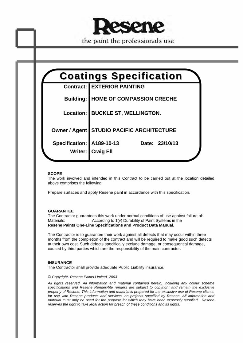
8
Emspeckw
Coatings Coatings SSpecificationpecification
Contract: EXTERIOR PAINTING
Building: HOME OF COMPASSION CRECHE
Location: BUCKLE ST, WELLINGTON.
Owner / Agent STUDIO PACIFIC ARCHITECTURE
Specification: A189-10-13 Date: 23/10/13 Writer: Craig Ell
SCOPE The work involved and intended in this Contract to be carried out at the location detailed above comprises the following: Prepare surfaces and apply Resene paint in accordance with this specification. GUARANTEE The Contractor guarantees this work under normal conditions of use against failure of: Materials: According to 1(v) Durability of Paint Systems in the Resene Paints One-Line Specifications and Product Data Manual. The Contractor is to guarantee their work against all defects that may occur within three months from the completion of the contract and will be required to make good such defects at their own cost. Such defects specifically exclude damage, or consequential damage, caused by third parties which are the responsibility of the main contractor. INSURANCE The Contractor shall provide adequate Public Liability insurance. © Copyright- Resene Paints Limited, 2003.
All rights reserved. All information and material contained herein, including any colour scheme specifications and Resene RenderRite renders are subject to copyright and remain the exclusive property of Resene. This information and material is prepared for the exclusive use of Resene clients, for use with Resene products and services, on projects specified by Resene. All information and material must only be used for the purpose for which they have been expressly supplied. Resene reserves the right to take legal action for breach of these conditions and its rights.

A189-10-13 9
Important Note: This page is numbered “9” because Resene preamble and special information pages 2-8 must be included to make this a fully complete Resene specification. If pages 2-8 are missing or have been removed please contact your local Resene representative. ---------------------------------------------------------------------------------------------------------------------------- 1.0 EXTERIOR PAINTED PLASTERED CONCRETE COLUMNS AND
ARCHITECTURAL FEATURES / LEDGES Condition: Previously painted in acrylic and in poor condition with loose and flaking paint
moss and mould etc Note: The painter should ensure all remaining paint is tightly adhered before repainting.
Any suspect paint should be removed back to a sound base – preferably to bare substrate
PREPARATION FOR PAINTING: 1.1 If any areas of moss or mould infestation exist then treat them with Resene Moss &
Mould Killer, diluted at the rate of 200 grams to 1 litre of clean water. Leave for up to 48 hours to achieve full kill. For heavy infestations more applications may be needed. Data Sheet D80
1.2 Thoroughly scrub down with a 25 % solution of Resene Paint Prep and Housewash
and water to remove all dirt, dust, grease, moss and mould residue, chalk, cobwebs and other contaminants. Rinse clean with fresh water Data Sheet D812
1.3 All paint that is flaking or unsound must be removed by using mechanical methods,
chemical stripper or high pressure water-blasting taking care not to damage either the substrate or the surrounding areas.
1.4 Cracks greater than 1 millimetre wide, and any damaged areas should be thoroughly
raked out to remove all loosely bound material and any contaminants. These areas should then be primed with Resene Concrete Primer prior to filling as outlined in the next clause. Data Sheet D405
1.5 Cracks and holes less than 3mm deep can be filled using Selley’s Permafill or similar
product in accordance with the label directions. Allow 24 hours dry before coating. Otherwise mix Resene Rockcote Multistop FRP bedding compound powder with water at the rate of 125 mls of water per kg of powder. Mixing is best achieved by mechanical drill mixer. Use minimal quantities of water to obtain a workable paste. Trowel the filling compound into the ‘prepared cracks’ and finish flush to surrounding concrete.
1.6 Seal all repairs as soon as practicable with Resene Limelock. Data Sheet D809 1.7 Prime repaired areas and any other bare concrete with Resene Concrete Primer.

A189-10-13 10
1.8 Any construction joints requiring repair should be thoroughly raked out and cleaned
then filled with a suitable sealant as per sealant manufacturer’s directions. If a sealant is painted over the paint may crack with movement and any cracks may transmit into the sealant with the risk of creating a leaking joint. Some sealants may also exude plasticiser into paint and create a tacky surface. Ensure all edges around windows, doors etc., are thoroughly weather tight. Ensure flashings and cappings have been installed where needed, are of adequate size, suitably primed and well fixed.
1.9 Cracks measuring less than 1mm should have Resene Brushable Crack Filler
brushed into them. Allow 3 hours before recoating. Data Sheet D811 PAINTING: 1.10 Apply a full coat of Resene AquaShield at the spreading rate of 12-13 square
metres per litre. Data Sheet D601 1.11 Apply a second coat of Resene AquaShield at the spreading rate of 12-13 square
metres per litre. 2.0 PAINTED EXTERIOR PLASTERED CONCRETE COLUMNS AND
ARCHITECTURAL FEATURE / LEDGES

A189-10-13 11
Condition: Previously unpainted and in poor condition with cracks to plaster and moss and mould to be prepared and painted in Resene AquaShield.
PREPARATION FOR PAINTING: 2.1 If any areas of moss or mould infestation exist then treat them with Resene Moss &
Mould Killer, diluted at the rate of 200 grams to 1 litre of clean water. Leave for up to 48 hours to achieve full kill. For heavy infestations more applications may be needed. Data Sheet D80
2.2 Thoroughly wash down with a 25 % solution of Resene Paint Prep and Housewash
and water to remove all dirt, dust, grease, moss and mould residue, cobwebs and other contaminants. Data Sheet D812
2.3 Water blast at pressures up to 3000psi (as appropriate for each area) to remove all
dirt, grease, moss and mould residue, dust, and any other contaminants. Allow the surface to dry thoroughly.
2.4 Spot prime any areas of powdery concrete with Resene Sureseal.
Data Sheet D42 2.5 Cracks greater than 1 millimetre wide, bugholes, and any damaged areas should be
thoroughly raked out to remove all loosely bound material and any contaminants. These areas should then be primed with Resene Concrete Primer prior to filling as outlined in the next clause. Data Sheet D405
2.6 Cracks & holes less than 3mm deep can be filled using Selley’s Permafill or similar
product in accordance with the label directions. Allow 24 hours dry before coating. Otherwise mix Resene Rockcote Multistop FRP bedding compound powder with water at the rate of 125 mls of water per kg of powder. Mixing is best achieved by mechanical drill mixer. Use minimal quantities of water to obtain a workable paste. Trowel the filling compound into the ‘prepared cracks’ and finish flush to surrounding concrete.
2.7 Seal all repairs as soon as practicable with Resene Limelock. Data Sheet D809 2.8 Any construction joints requiring repair should be thoroughly raked out and cleaned
then filled with a suitable sealant as per sealant manufacturer’s directions. If a sealant is painted over the paint may crack with movement and any cracks may transmit into the sealant with the risk of creating a leaking joint Some sealants may also exude plasticiser into paint and create a tacky surface. Ensure all edges around windows, doors etc., are thoroughly weather tight. Ensure flashings and cappings have been installed where needed, are of adequate size, suitably primed and well fixed.
2.9 Cracks measuring less than 1mm should have Resene Brushable Crack Filler
brushed into them. Allow 3 hours before recoating. Data Sheet D811 PAINTING:

A189-10-13 12
2.10 Apply a full coat of Resene X-200 by brush or roller at the spreading rate of 5 square metres per litre. Allow 3 hours dry time.
2.11 Apply a full coat of Resene AquaShield at the spreading rate of 12-13 square
metres per litre. Data Sheet D601 2.12 Apply a second coat of Resene AquaShield at the spreading rate of 12-13 square
metres per litre. N.B Good access to the surface must be provided. The use of rollers with extension
handles longer than 1.3 metres is not an adequate means of application for X-200. A Lambswool Roller sleeve is recommended for X-200 application.
3.0 PAINTED EXTERIOR BRICK WALL Condition: Previously painted in acrylic and in average condition

A189-10-13 13
Note: The painter should ensure all remaining paint is tightly adhered before repainting. Any suspect paint should be removed back to a sound base – preferably to bare substrate
PREPARATION FOR PAINTING: 3.1 Thoroughly scrape to remove as much old paint as is practicable. To areas of
remaining paint, apply a full coat of Resene Strip-Off Paint Stripper and leave for 1-2 hours to soften the paint. Taking care not to damage the substrate, remove as much of the softened old paint as possible using a suitable scraper. Repeat the process if any paint remains. Data Sheet D81
Note 1: Alternatively, all old paint may be carefully removed by use of Sea to Sky Stripper, hot air guns, mechanical sanders or other appropriate means that will not damage the timber or allow the uncontrolled release of lead containing paint or debris into the environment.
3.2 Thoroughly scrub down with a 25% solution of Resene Paint Prep and Housewash
in water to remove all residue from paint strippers and any other contaminants. Thoroughly rinse clean with fresh water to remove all cleaning residue. Data Sheet D812
3.3 Low pressure water-blast or thoroughly hose down to remove all residue from the
Paint Prep and Housewash cleaning process, all salts and any other contaminants. Note: The substrate must be allowed to dry out thoroughly before painting. 3.4 Remove any efflorescence from brickwork prior to the application of the Aquapel.
Employ careful wire-brushing /scraping /wet sanding or power-tools as appropriate. WATER REPELLENCY TREATMENT: 3.5 Apply a saturation coat of Resene Solventborne Aquapel at the spreading rate of 8-10
square metres per litre. Allow 24 hours dry. Data Sheet D65 Note: Applicators should be requested to contact the local specification writer within Resene
with the surface area to be treated so that quantities can be advised and followed up on.
4.0 EXTERIOR BRICK WALL Condition: Unpainted brick work which is generally dirty with areas of moss and mould
etc

A189-10-13 14
Note: Resene recommend painting brickwork for best results. PREPARATION FOR PAINTING: 4.1 All surfaces should be clean and free from dirt, grease, mould and any other
contaminants. Ensure flashings and cappings have been installed where needed, are of adequate size, suitably primed and well fixed.
4.2 Remove any efflorescence from brickwork prior to the application of the Aquapel.
Employ careful wire-brushing /scraping /wet sanding or power-tools as appropriate. WATER REPELLENCY TREATMENT: 4.3 Apply a saturation coat of Resene Solventborne Aquapel at the spreading rate of 8-10
square metres per litre. Allow 24 hours dry. Data Sheet D65 Note: Applicators should be requested to contact the local specification writer within Resene
with the surface area to be treated so that quantities can be advised and followed up on.
5.0 PAINTED EXTERIOR PLASTERED PARAPETS, BATTLMENTS AND
CRENELLATIONS Condition: Previously painted in acrylic and in poor condition with loose and flaking
paint, with moss, mould and lichen. PREPARATION FOR PAINTING:

A189-10-13 15
5.1 If any areas of moss or mould infestation exist then treat them with Resene Moss & Mould Killer, diluted at the rate of 200 grams to 1 litre of clean water. Leave for up to 48 hours to achieve full kill. For heavy infestations more applications may be needed. Data Sheet D80
5.2 Thoroughly scrub down with a 25 % solution of Resene Paint Prep and Housewash
and water to remove all dirt, dust, grease, moss and mould residue, chalk, cobwebs and other contaminants. Rinse clean with fresh water Data Sheet D812
5.3 All paint that is flaking or unsound must be removed by using mechanical methods,
chemical stripper or high pressure water-blasting taking care not to damage either the substrate or the surrounding areas.
5.4 Cracks greater than 1 millimetre wide, and any damaged areas should be thoroughly
raked out to remove all loosely bound material and any contaminants. These areas should then be primed with Resene Concrete Primer prior to filling as outlined in the next clause. Data Sheet D405
5.5 Cracks and holes less than 5mm deep can be filled using Selley’s Permafill or similar
product in accordance with the label directions. Allow 24 hours dry before coating. Otherwise mix Resene Rockcote Multistop FRP bedding compound powder with water at the rate of 125 mls of water per kg of powder. Mixing is best achieved by mechanical drill mixer. Use minimal quantities of water to obtain a workable paste. Trowel the filling compound into the ‘prepared cracks’ and finish flush to surrounding concrete.
5.6 Seal all repairs as soon as practicable with Resene Limelock. Data Sheet D809 5.7 Prime repaired areas and any other bare concrete with Resene Concrete Primer. 5.8 Any construction joints requiring repair should be thoroughly raked out and cleaned
then filled with a suitable sealant as per sealant manufacturers directions. If a sealant is painted over the paint may crack with movement and any cracks may transmit into the sealant with the risk of creating a leaking joint Some sealants may also exude plasticiser into paint and create a tacky surface. Ensure all edges around windows, doors etc., are thoroughly weather tight. Ensure flashings and cappings have been installed where needed, are of adequate size, suitably primed and well fixed.
5.9 Cracks measuring less than 1mm should have Resene Brushable Crack Filler
brushed into them. Allow 3 hours before recoating. Data Sheet D811 5.10 Where necessary restore an even surface appearance by careful application of
Resene X-200 to repaired areas. PAINTING: 5.11 Apply a full coat of Resene X-200 by brush, roller or spray at the spreading rate of 5
square metres per litre. Data Sheet D62 5.12 Apply a full coat of Resene AquaShield at the spreading rate of 12-13 square
metres per litre. Data Sheet D601

A189-10-13 16
5.13 Apply a second coat of Resene AquaShield at the spreading rate of 12-13 square metres per litre.
N.B Good access to the surface must be provided. The use of rollers with extension
handles longer than 1.3 metres is not an adequate means of application for X-200. A Lambswool Roller sleeve is recommended for X-200 application.
6.0 UNPAINTED EXTERIOR TIMBER FASCIAS Condition: Unpainted weathered and cracked possibly Matai or Totara timber fascias, Special Notes Painting over old weathered unpainted timber is likely to have limited success
because backs of boards and timber end grains may not have been sealed properly during erection of the building.

A189-10-13 17
The installation of soakers over all joint areas will assist the performance of the new paint system. Total removal of all mould and dirt and restoration of weathered timber fibres is essential.
SURFACE PREPARATION 6.1 If any areas of moss or mould infestation exist then treat them with Resene Moss &
Mould Killer, diluted at the rate of 200 grams to 1 litre of clean water. Leave for up to 48 hours to achieve full kill. For heavy infestations more applications may be needed. Data Sheet D80
6.2 Thoroughly scrub down with a 25 % solution of Resene Paint Prep and Housewash
and water to remove all dirt, dust, grease, any moss and mould residue, chalk, cobwebs and other contaminants. Data Sheet D812
6.3 Thoroughly hose down to remove all dirt, grease, moss and mould residue, surface
chalk, dust, and other cleaning residues. Note: The timber must be allowed to dry out thoroughly before painting commences. 6.4 Remove or punch in any rusty nails and replace with stainless steel nails or
equivalent. Thoroughly sand to remove any grey, weathered timber and to produce a smooth sound surface for painting. If timber is roughsawn then brushing with a stiff nylon brush can be carefully employed for this purpose. Ensure any sharp arrisses are sanded to a rounded profile.
6.5 Apply a saturation coat of Resene TimberLock at about 5 square metres per litre.
Allow 24 hours dry then wipe off any still tacky material with a turps wet rag. Data Sheet D48
6.6 Apply a full primer coat of Resene Quick Dry Acrylic Primer Undercoat at the
spreading rate of 12 square metres per litre. Apply finishing coats as soon as possible to ensure the best performance of the new paint system.Data Sheet D45
6.7 Fill all nail holes, damaged or split timber with Selley’s Ready Mixed Permafill applied
in accordance with manufacturers instructions. Spot prime filler (after a 24 hour dry) with Resene Quick Dry Acrylic Primer Undercoat
PAINTING: 6.8 Apply a full coat of Resene Sonyx 101 at the spreading rate of 12 square metres
per litre. A legend 63-88mm brush is recommended. Data Sheet D30 6.9 Apply a second coat of Resene Sonyx 101 at the spreading rate of 12 square
metres per litre. 7.0 PAINTED EXTERIOR TIMBER FASCIAS Condition: Previously painted possibly Matai or Totara timber fascias in very poor
condition with numerous cracks and peeling paint to be completely stripped before being repainted in Sonyx 101 semi-gloss acrylic.
WARNING! LEAD BASED PAINTS MAY BE PRESENT

A189-10-13 18
Before stripping off old paint tests should be done to ensure the old paint does not contain lead. Paint flakes with layers older than 1970 are likely to have lead in them. If lead based paints are identified on this job then the OSH Guidelines for the Management of Lead-based Paint must be read and followed. Where these guidelines are in conflict with any part of this specification, the guidelines must take precedence. Flakes of lead paints and any sanding dust need to be carefully contained and disposed of. PREPARATION FOR PAINTING: 7.1 Thoroughly scrape to remove as much old paint as is practicable. To areas of
remaining paint, apply a full coat of Resene Strip-Off Paint Stripper and leave for 1-2 hours to soften the paint. Taking care not to damage the substrate, remove as much of the softened old paint as possible using a suitable scraper. Repeat the process if any paint remains. Data Sheet D81
Note 1: Alternatively, all old paint may be carefully removed by use of Sea to Sky Stripper, hot air guns, mechanical sanders or other appropriate means that will not damage the timber or allow the uncontrolled release of lead containing paint or debris into the environment.
7.2 Thoroughly scrub down with a 25% solution of Resene Paint Prep and Housewash
in water to remove all residue from paint strippers and any other contaminants. Thoroughly rinse clean with fresh water to remove all cleaning residue. Data Sheet D812
7.3 Thoroughly sand to remove any grey, weathered timber and to produce a smooth,
sound surface for painting. Ensure any sharp edges are sanded to give a rounded profile. Remove or punch in any rusty nails and replace with galvanised or stainless steel nails as is appropriate. Scrape out all cracks and splits in timber to obtain a sound surface for filling. Data Sheet D87
7.4 Treat all cracks and splits in timber and any other areas of suspected mould
infestation with Resene Moss & Mould Killer, diluted at the rate of 200 grams to 1 litre of clean water. Leave for up to 48 hours to achieve full kill. For heavy infestations, more applications may be needed. Thoroughly scrub down with fresh water to remove all moss and mould residue. Rinse thoroughly with clean water. Allow to dry. Data Sheet D80
7.5 Apply a saturation coat of Resene TimberLock Preserver/Conditioner at an
approximate spreading rate of 5-10 square metres per litre. Allow 24 hours to dry. Wipe off any tacky material with a Turps wet rag. Timber Lock will help reconstitute weathered timber fibres and also provide good fungal resistance. Data Sheet D48
7.6 Fill all cracks, splits and holes in timber with Resene Epox-O-Bond Epoxy Filler as
per directions on label. We recommend holes are over filled then power sanded back to a smooth finish when the filler has cured for 24 hours. Data Sheet D808
PAINTING: 7.7 Apply a full primer coat of Resene Quick Dry Acrylic Primer Undercoat at the
spreading rate of 12-13 square metres per litre. Data Sheet D45 Note 2 If the timber is Cedar or Redwood then the stain blocking primer, Resene Wood
Primer should be used Data Sheet D40
A189-10-13 19
7.8 Apply a full coat of Resene Sonyx 101 at the spreading rate of 12 square metres
per litre. A legend 63-88mm brush is recommended. Data Sheet D30 7.9 Apply a second coat of Resene Sonyx 101 at the spreading rate of 12 square
metres per litre. 8.0 PAINTED EXTERIOR TIMBER WINDOWS Condition: Previously painted native timber windows in poor condition with loose and
peeling paint, rusting nails and cracked or loose putty, to be stripped. WARNING! LEAD BASED PAINTS MAY BE PRESENT Before stripping off old paint tests should be done to ensure the old paint does not contain lead. Paint flakes with layers older than 1970 are likely to have lead in them. If lead based paints are identified on this job then the OSH Guidelines for the Management of Lead-based Paint must be read and followed. Where these guidelines are in conflict with any part of this specification, the guidelines must take precedence. Flakes of lead paints and any sanding dust need to be carefully contained and disposed of. PREPARATION FOR PAINTING: 8.1 Thoroughly scrape to remove as much old paint as is practicable. To areas of
remaining paint, apply a full coat of Resene Strip-Off Paint Stripper and leave for 1-2 hours to soften the paint. Taking care not to damage the substrate, remove as much of the softened old paint as possible using a suitable scraper. Repeat the process if any paint remains. Data Sheet D81
Note 1: Alternatively, all old paint may be carefully removed by use of Sea to Sky Stripper, hot air guns, mechanical sanders or other appropriate means that will not damage the timber or allow the uncontrolled release of lead containing paint or debris into the environment.
8.2 If any areas of moss or mould infestation exist then treat them with Resene Moss &
Mould Killer, diluted at the rate of 200 grams to 1 litre of clean water. Leave for up to 48 hours to achieve full kill. For heavy infestations more applications may be needed. Data Sheet D80
8.3 Thoroughly scrub down with a 25% solution of Resene Paint Prep and Housewash
in water to remove all moss and mould residue and any other contaminants. Thoroughly rinse clean with fresh water to remove all cleaning residue. Allow timber to dry out thoroughly before painting. Data Sheet D812
8.4 Thoroughly sand to remove any grey, weathered timber and to produce a smooth,
sound surface for painting. Ensure any sharp edges are sanded to give a rounded profile. Remove or punch in any rusty nails and replace with galvanised or stainless steel nails as is appropriate.
8.5 Apply a saturation coat of Resene TimberLock Preserver/Conditioner at an
approximate spreading rate of 5-10 square metres per litre. Allow 24 hours to dry. Wipe off any tacky material with a Turps wet rag. Timber Lock will help reconstitute weathered timber fibres and also provide good fungal resistance. Data Sheet D48

A189-10-13 20
8.6 Any cracking putty on windows should be scraped out and a clean substrate prepared as per previous clauses. Spot prime any bare timber with Resene Wood Primer then reglaze after 24 hours dry with Red Devil Glazing Compound or Bostik Synthetic Putty or equivalent product in accordance with manufacturers application instructions New putty should be allowed to harden up for 24 hours before priming with Resene Wood Primer. Data Sheet D40
Note 2: If Totara or Matai timber is present then spot prime bare timber to be reglazed with
Resene Quick Dry Acrylic Primer Undercoat. Allow 4 hour dry prior to reglazing. Data Sheet D45
8.7 Apply a full primer coat of Resene Quick Dry Acrylic Primer Undercoat at the
spreading rate of 12-13 square metres per litre. Note 3: If Cedar or Redwood timber is present then the stain blocking primer Resene Wood
Primer should be used. 8.8 Fill all nail holes, damaged or split timber with Selleys Ready Mixed Permafill applied
in accordance with manufacturers instructions. Spot prime filler (after a 24 hour dry) with Resene Quick Dry Acrylic Primer Undercoat.
PAINTING: 8.9 Apply a full coat of Resene Lustacryl at the spreading rate of 12 square metres
per litre. Data Sheet D310 8.10 Apply a second full coat of Resene Lustacryl at the spreading rate of 12 square
metres per litre. 9.0 NEW EXTERIOR TIMBER WINDOWS Condition: New timber windows to be painted in Resene Lustacryl waterborne enamel
semi-gloss. Special Notes The performance of paint systems on exterior doors and windows is dependent on
careful surface preparation and painting. Top and bottom surfaces must have the full coating system applied. Best done before hanging.
Particular attention is needed to ensure there are proper flashings above doors and windows and that the sides of joinery are properly weatherproofed by use of adequate scribers or sealants.

A189-10-13 21
All edges of the joinery and future hidden surfaces should be primed before assembly with particular attention to priming the end grains properly.
Attention is needed to ensure all sharp edges on joinery are sanded to a rounded profile before painting.
Newly primed timber should not be left to weather but topcoated as soon as practicable.
If timber is LOSP Preservative treated then it must not be painted if solvents from the LOSP treatment are still in the timber. Many problems may be encountered with the new paint system if timber is painted while these solvents are still in the timber.
Any bare timber that has been left to weather should be thoroughly sanded back to a sound timber surface, treated for mould (use a 20% solution of Resene Moss & Mould Killer and leave 48 hours) and then thoroughly washed clean (use 25% solution of Resene Paint Prep and Housewash in water). Data Sheet D80 & D812
Any factory primed timber must be thoroughly sanded back and then given a full coat of Resene Wood Primer. Data Sheet D40
For any bare weathered timber or bare Cedar Resene strongly recommend additional treatment with Resene TimberLock. Timber Lock will help reconstitute weathered timber fibres and also provide good fungal resistance. Data Sheet D48
For Redwood or Cedar use Resene Wood Primer in place of Quick Dry Acrylic Primer Undercoat to prevent stain bleeding.
This specification assumes all glazing is in sound condition. PREPARATION FOR PAINTING: 9.1 Sand any sharp arrisses on timber profiles to a rounded corner. 9.2 Ensure all surfaces are clean and free from contamination before painting. 9.3 Apply a full coat of Resene Quick Dry Acrylic Primer Undercoat at the spreading rate
of 12 square metres per litre. Brush well into punched nail holes or other areas requiring filling. Data Sheet D45
Note: If Cedar or Redwood timber has been used, then Resene Wood Primer should be
used as the primer 9.4 Fill all primed nail holes or areas of damaged timber with Selley’s Ready Mixed
Permafill applied in accordance with manufacturers instructions. Sand smooth and spot prime filler (after 24 hours dry) with the same Resene primer as was used for the bare timber.
9.5 Any fresh putty should be allowed to harden up before priming with Resene Wood
Primer. How long depends on the type of glazing compound used.Data Sheet D40 PAINTING: 9.6 Apply a full coat of Resene Lustacryl at the spreading rate of 12 square metres
per litre. Data Sheet D310 9.7 Apply a second full coat of Resene Lustacryl at the spreading rate of 12 square
metres per litre.

A189-10-13 22
10.0 EXTERIOR, PAINTED, RUSTY CAST IRON VENTS Condition: Previously painted in enamel paint and showing signs of rusting. Only hand tool
cleaning is possible. PREPARATION FOR PAINTING: 10.1 If any areas of moss or mould infestation exist then treat them with Resene Moss &
Mould Killer, diluted at the rate of 200 grams to 1 litre of clean water. Leave for up to 48 hours to achieve full kill. For heavy infestations more applications may be needed. Data Sheet D80
10.2 Mix one part of Resene Roof Wash & Paint Cleaner with three parts of fresh water.
Apply a liberal wash of this mixture to the surface with a nylon bristle brush or broom. Thoroughly scrub the surface to ensure complete removal of all dirt, dust, grease,

A189-10-13 23
any moss and mould residue, chalk, cobwebs and other contaminants. Data Sheet D88
10.3 Waterblast or wash down with copious quantities of fresh water to remove all salts
and Roof Wash residue. Waterblast or scrape to remove as much flaking paint and rust as is practicable.
10.4 Thoroughly wire brush to remove as much rust as possible. Power tools may be
used if available. In areas where there is underfilm corrosion the surface paint should be scraped away to allow better access to the rust. At this stage any unsound old paint should also be removed.
Note 1: The performance of the subsequent paint system will be dependent on the
thoroughness of this preparation stage. Note 2: For best results abrasive blast cleaning of rust areas back to shiny metal is the only
really effective preparation. This specification must be considered as a compromise arrived at because of time, cost or access difficulties.
10.5 Thoroughly abrade all old paint to provide a good key for adhesion. 10.6 Thoroughly sand all old paint to provide a good key for adhesion. Sand areas of
flaking paint back to a feathered edge. Remove sanding dust and immediately spot prime bare steel with Resene Armourcote 221 to give a dry film build of 50 microns. Data Sheet RA36
PAINTING: 10.7 Apply a full coat of Resene Uracryl 403 by brush or roller at the spreading rate of 10
square metres per litre. Data Sheet RA56 10.8 Apply a second coat of Resene Uracryl 403 by brush or roller at the spreading rate of
10 square metres per litre. 11.1 NEW ZINC SPRAYED STEEL VENTS Condition: New steel work that has been appropriately prepared and given a metal spray
coating of zinc. Arc spray zinc must have been applied to achieve a film thickness of 150 microns as per ANSI/AWS C2.18-93 and SSPC CS-Guide23,00 standards.
PREPARATION FOR PAINTING: 11.2 Mix one part of Resene Roof Wash & Paint Cleaner with three parts of fresh water.
Apply a liberal wash of this mixture to the surface with a nylon bristle brush or broom. Thoroughly scrub the surface to ensure complete removal of all grease and other contaminants. Rinse thoroughly with fresh water and allow to dry. Test the surface is degreased by wiping with clean cotton wool. Data Sheet D88

A189-10-13 24
11.3 Thoroughly sand the arc spray zinc to remove any spikes and excessive surface roughness that may protrude through the subsequent paint system. Then thoroughly vacuum the surface to remove all sanding dust.
PAINTING: 11.4 Apply a uniform sealer coat of Resene Armourcote 220 thinned 15-30% to seal off
any surface porosity. This is to penetrate into the zinc substrate and to provide a sealed surface. Data Sheet RA34
Note 1: Any edges and welds shall have a stripe coat of each specified coating applied to
them, to ensure correct film build is achieved, and to maximise the potential of the paint system.
11.5 Apply a build coat of Resene Armourcote 220 to achieve a dry film thickness of 100
microns. 11.6 Apply Resene Uracryl 403 to achieve a dry film thickness of 50 – 75 microns.
Data Sheet RA56 Note 2: On completion of painting, all crevices shall have a suitable type silicon or mastic sealant applied into the as per manufacturer’s instruction to aid in corrosion prevention. ATTENTION - ISOCYANATES The OSH ‘Approved Code of Practice for the Safe Use of Isocyanates’ should be read and followed if Uracryl 403 is to be spray applied.

A189-10-13 25
Interior 12.0 PAINTED INTERIOR TIMBER WINDOWS – CLEAR FINISH Condition: Previously painted in enamel native timber in poor condition to be completely
stripped PREPARATION FOR PAINTING: 12.1 Thoroughly scrape to remove as much old paint as is practicable. To areas of
remaining paint, apply a full coat of Resene Strip-Off Paint Stripper and leave for 1-2 hours to soften the paint. Taking care not to damage the substrate, remove as much of the softened old paint as possible using a suitable scraper. Repeat the process if any paint remains. Scrub with fresh water to remove any remaining stripper. Data Sheet D81
12.2 If any areas of moss or mould infestation exist then treat them with Resene Moss &
Mould Killer, diluted at the rate of 200 grams to 1 litre of clean water. Leave for up to 48 hours to achieve full kill. For heavy infestations more applications may be needed. Data Sheet D80
12.3 Thoroughly wash down with a 2% solution of Resene Interior Paintwork Cleaner
Concentrate and water to remove all dirt, grease, stains, dust and other contaminants. Rinse thoroughly with clean water. Allow to dry.
12.4 Thoroughly sand to a smooth, clean surface. Sand any sharp arrisses to a rounded
profile. Wipe surface with a damp rag to remove dust. Note: Resene strongly recommend a saturation coat of Resene Timberlock at the
spreading rate of 5 square metres per litre. Allow 24 hours dry then wipe off any material that is still tacky with a Turps dampened rag. Data Sheet D48
12.5 Apply a full sealer coat of Resene Aquaclear Satin at the spreading rate of 12
square metres per litre. Data Sheet D59 12.6 Fill all cracks and nail holes etc. with Red Enz Wood Filler or equivalent product
applied according to manufacturers directions. Carefully remove excess filler. Allow at least 60 minutes dry.
PAINTING: 12.7 Apply a full coat of Resene Qristal Poly Satin at the spreading rate of 16 square
metres per litre. 12.8 Lightly sand to remove all nibs etc. Dust down. 12.9 Apply another coat of Resene Qristal Poly Satin at the spreading rate of 16 square
metres per litre.

A189-10-13 26
13.0 NEW INTERIOR TIMBER WINDOWS – CLEAR FINISH Condition: New timber to be clear finished in Resene in Qristal Poly-Satin Urethane PREPARATION FOR CLEAR FINISHING 13.1 Thoroughly sand to a smooth, clean surface. Sand any sharp arrisses to a rounded
profile. Wipe surface with a damp rag to remove dust. Note: Resene strongly recommend a saturation coat of Resene Timberlock at the
spreading rate of 5 square metres per litre. Allow 24 hours dry then wipe off any material that is still tacky with a Turps dampened rag. Data Sheet D48
13.2 Apply a full sealer coat of Resene Aquaclear Satin at the spreading rate of 12
square metres per litre. Data Sheet D59 13.3 Fill all cracks and nail holes etc. with Red Enz Wood Filler or equivalent product
applied according to manufacturers directions. Carefully remove excess filler. Allow at least 60 minutes dry.
CLEAR FINISHING 13.4 Apply a full coat of Resene Qristal Poly Satin at the spreading rate of 16 square
metres per litre. 13.5 Lightly sand to remove all nibs etc. Dust down. 13.6 Apply another coat of Resene Qristal Poly Satin at the spreading rate of 16 square
metres per litre.

A189-10-13 27
Surface texture and abnormal surface porosity will effect either the spreading rate or the coverage achieved. Allowance for this should be made in the quotation. This specification should be read in conjunction with the manufacturers recommendations contained in the relevant technical data sheets. Site Assistance Resene Representatives will visit specific job sites as required to assist with advice on adequacy of preparation; special mixing requirements; standard of application etc. However this should not be regarded as ‘supervision’, but simply ‘site assistance’. Craig Ell Andy Provan Thorndon Quay Head Office, Lower Hutt Architectural Services Representative Technical Services Manager

1902 Home of Compassion Creche
© CIL Masterspec 2013 APR 7151 SANITARY FIXTURES, TAPWARE & ACCESSORIES Page 1
7151 SANITARY FIXTURES, TAPWARE & ACCESSORIES – Rev A
1. GENERAL This section relates to the supply and installation of sanitary fixtures, tapware and
sanitary accessories. 1.1 RELATED WORK Refer to glazing section/s for frameless shower and bath screens not included in this
section. Refer to the electrical section/s for electrical connection of accessories. Refer to 7421 SANITARY SYSTEMS for the supply and fitting of waste disposal pipework
Documents 1.2 DOCUMENTS Refer to the general section 1233 REFERENCED DOCUMENTS. The following
documents are specifically referred to in this section: NZBC E3/AS1 Internal moisture NZBC F2/AS1 Hazardous building materials NZBC G1/AS1 Personal hygiene NZBC G12/VM1 Water supplies NZBC G12/AS1 Water supplies NZBC G13/AS1 Foul water AS/NZS 1730 Washbasins AS/NZS 3500.1 Plumbing and drainage - water services AS/NZS 3500.2 Plumbing and drainage - sanitary plumbing and drainage Plumbers, Gasfitters and Drainlayers Act 2006 Documents listed above and cited in the clauses that follow are part of this specification.
However, this specification takes precedence in the event of it being at variance with the cited document.
Requirements 1.3 QUALIFICATIONS Plumbers to be experienced competent workers, familiar with the materials and the
techniques specified. Carry out all work under the direct supervision of a Certifying Plumber under the Plumbers, Gasfitters and Drainlayers Act 2006.
1.4 SAMPLES Submit samples on request of nominated tapware, along with the relevant manufacturers'
technical literature for review. 1.5 SUPPLIER A specialist in the supply of tapware, and employing experienced architectural
representatives available to assist during the course of the installation. 2. PRODUCTS 2.1 SANITARY FIXTURES Refer to SCHEDULE OF SELECTIONS for product selection. 2.2 TAPWARE Refer to SCHEDULE OF SELECTIONS for product selection. 3. EXECUTION Conditions - sanitary fixtures

1902 Home of Compassion Creche
© CIL Masterspec 2013 APR 7151 SANITARY FIXTURES, TAPWARE & ACCESSORIES Page 2
3.1 DELIVERY Only deliver to the site fixtures or fittings that can be immediately unloaded into suitable
storage or be placed for direct installation. 3.2 STORAGE AND HANDLING Take delivery of and store components complete with protective casings and coverings in
areas that are enclosed, clean and dry and where no work is being done. Remove protection only to the extent that will allow installation.
3.3 QUALITY STANDARDS Installation work to comply with NZBC G1/AS1, NZBC G12/VM1, NZBC G12/AS1, NZBC
G13/AS1 and the fixture manufacturer's requirements. 3.4 SUBSTRATE Ensure substrate and fixings will allow work of the specified standard. 3.5 CO-ORDINATION Do not proceed if the points of supply and drainage services do not match the points of
the fixtures without force or distortion. 3.6 INSTALLATION REQUIREMENTS Install to NZBC G1/AS1, NZBC G12/VM1, NZBC G12/AS1, NZBC G13/AS1, NZBC
E3/AS1 and to the fixture manufacturer's installation requirements for each component. 3.7 PROVIDE SUPPORT Confirm fixing points needed for each unit and provide solid blocking at each fixing
bracket location. Installation - sanitary fixtures 3.8 INSTALLING VITREOUS CHINA FIXTURES Install to NZBC G1/AS1: Part 3, G12/AS1, G13/AS1 and AS/NZS 3500.2. Carry out
preparatory and assembly work, including connections to supply and drainage services and the application of slurries and sealants in sequence. Fit the toilet pan in position, plumb, level, flush and rigid without stressing the attachment points of the component. Connect through trap to the drainage system.
3.9 INSTALLING CISTERNS Fit firmly in place and connect the specified cisterns from the supply services through the
flush pipes to the relative fixtures in the positions as detailed all plumb and level. Installation - Basins 3.10 INSTALLING WASHBASINS Install to NZBC G1/AS1, AS/NZS 1730. Set basins firmly to walls or vanities as detailed
and to comply with NZBC E3/AS1. Connect through trap to the drainage system. Completion 3.11 REPLACE Replace damaged or marked elements. 3.12 PROTECTIVE COVERINGS Leave fixtures, fittings and accessories clean and unblemished with stickers and
protective coverings removed, with supply and drainage connections and all parts fully operating and working. Leave the whole of this work free of blemishes, undamaged and to the standard of finish required for following work.
3.13 REMOVE Remove debris, unused materials and elements from the site. 4. SELECTIONS Refer to ‘Schedule of Selections’ in drawing set.

1902 Home of Compassion Creche
© CIL Masterspec 2013 APR 7151 SANITARY FIXTURES, TAPWARE & ACCESSORIES Page 3

1902 Home of Compassion Creche
© CIL Masterspec 2013 JUN 7411C CONTINUOUS SPOUTING RAINWATER SYSTEMS Page 1
7411C CONTINUOUS SPOUTING RAINWATER SYSTEMS – Rev A 1. GENERAL This section deals with Continuous Spouting NZ Ltd rainwater disposal systems
including spouting and downpipes, in various metal substrates. 1.1 RELATED WORK Refer to 4311 PROFILED METAL ROOFING for roofing Refer 4421 BITUMEN BASED SHEET ROOFING for membrane/gutter roofing Refer to 4224 TIMBER EXTERIOR TRIM for fascia 1.2 ABBREVIATIONS The following abbreviations are used throughout this part of the specification: BMT Base metal thickness NZMRM New Zealand Metal Roofing Manufacturers Association Documents 1.3 DOCUMENTS Refer to the general section 1233 REFERENCED DOCUMENTS. The following
documents are specifically referred to in this section: NZBC E1/AS1 Surface Water NZBC E2/AS1 External moisture BS EN 988 Zinc and zinc alloys. Specification for rolled flat products for building AS 1566 Copper and copper alloys - Rolled flat products AS/NZS 2728 Prefinished/prepainted sheet metal products for interior/exterior
building applications - Performance requirements NZMRM NZ Metal roof and wall cladding - Code of practice Documents listed above and cited in the clauses that follow are part of this specification.
However this specification takes precedence in the event of it being at variance with the cited document.
1.4 MANUFACTURER'S DOCUMENTS Continuous Spouting New Zealand Ltd documents relating to work in this section are:
Continuous Spouting, Fascia, Spouting, Downpipes. Copies of the above literature are available from Continuous Spouting NZ Ltd: Web: www.continuous.co.nz Email: [email protected] Telephone: 0800 50 1993 Area Contact E-mail Wellington [email protected] Warranties 1.5 MANUFACTURER'S WARRANTY Provide Continuous Spouting NZ Ltd warranty covering material and installation in the
standard form. Product performance, life expectancy and warranty are dependent upon environment,
maintenance and material selection. Refer to Continuous Spouting NZ Ltd for the appropriate warranty terms, conditions and environmental considerations based on performance requirements to AS/NZS 2728.
Refer to the general section 1237 WARRANTIES for details of when completed warranty
must be submitted. Requirements

1902 Home of Compassion Creche
© CIL Masterspec 2013 JUN 7411C CONTINUOUS SPOUTING RAINWATER SYSTEMS Page 2
1.6 NO SUBSTITUTIONS Substitutions are not permitted to any specified system, or associated components and
products. 1.7 QUALIFICATIONS Continuous Spouting NZ Ltd installers and local agents to be experienced competent
tradesmen, familiar with the materials and the techniques specified. Performance 1.8 TEST Test the completed rainwater disposal system with water to ensure spoutings are laid to
correct falls, that both spouting and downpipes are unobstructed and that no ponding occurs in spoutings.
1.9 DESIGN Layout, falls and capacity of spouting to falls and the size and position of downpipes to
comply with NZBC E1/AS1. Refer to NZMRM NZ Metal roof and wall cladding - Code of practice recommendations, sections 8.4 Gutters and 8.5 Downpipes.
2. PRODUCTS Materials 2.1 ZINCALUME™ Zincalume™ AZ150 coated steel, to AS/NZS 2728. Products 2.2 SPOUTING Manufactured by Continuous Spouting NZ Ltd using onsite plant to provide made to
measure continuous lengths of spouting. Complete with matching brackets and screws. Spouting to be sized to comply with NZBC E1/AS1 and installed to NZBC E2/AS1 8.1.6. Refer to SELECTIONS for type.
2.3 DOWNPIPES Material to match spouting complete with Munzing stand-off brackets, screw fixed. Components 2.4 DOWNPIPE SPREADERS To comply with E2/AS1 figure 20 2.5 RAINWATER HEADS Material to match the spouting. 2.6 DROPPERS Material to match spouting, sized to fit inside the downpipe. 2.7 BRACKETS Galvanised steel Munzing type, srew fixed to wall. 2.8 SEALANT Neutral cure silicone or Fixall Hitack MS Polymer sealant. 3. EXECUTION Conditions 3.1 HANDLE AND STORE Handle and store downpipes, spouting and accessories to avoid damage. Store on site
under cover, on a clean level area, stacked to eliminate movement and away from work in

1902 Home of Compassion Creche
© CIL Masterspec 2013 JUN 7411C CONTINUOUS SPOUTING RAINWATER SYSTEMS Page 3
progress. Avoid exposure to sunlight if strippable film is still on the product. 3.2 SUBSTRATE Check that fascias, barges or cladding are level and true to line and face and will allow
work of the required standard without distortion to the product alignment. Do not proceed until they are up to standard.
3.3 THERMAL MOVEMENT Make adequate provision in the fixing and jointing of the spouting for thermal movement
in the length of the spouting. 3.4 CORROSION Separate metals subject to electrolytic action from each other and from treated timber,
concrete and other lime substances by space, painting of surfaces, taping, or separator strips.
Check compatibility of metals used for rainwater goods, against the materials being used
for roofing and flashings. Application - metal 3.5 INSTALL METAL SPOUTING Establish minimum falls necessary (minimum 1:500) to outlets to prevent ponding and
screw fix brackets true-to-line between 800mm to 900mm centres maximum. In areas where snow fall is possible the centres should be reduced to 600mm and snow strap fitted. Cut out neatly for and fit the pre-formed downpipe dropper and seal and rivet around the joint. All installation to NZMRM NZ Metal roof and wall cladding - Code of practice recommendations section 8.4 Gutters.
3.6 INSTALL METAL DOWNPIPES Form downpipes complete with offsets and shoes as needed with all joints lapped and
sealed as required. Screw fix with matching pipe clips to rigidly stand plumb to the wall, and discharging into the stormwater gully or pipe inlet. All installation to NZMRM NZ Metal roof and wall cladding - Code of practice recommendations section 8.5 Downpipes.
Application - general 3.7 INSTALLATION GENERALLY Install to NZMRM NZ Metal roof and wall cladding - Code of practice recommendations
where not otherwise specified. 3.8 INSTALL DOWNPIPE SPREADERS Install downpipe spreaders where required to NZMRM NZ Metal roof and wall cladding -
Code of practice, clause 8.5.1 Downpipe spreaders. Proved spreaders to downpipes that discharge on to a lower roof. Ensure spreaders do not discharge directly over fasteners or laps. Spreaders to have holes equalling twice the diameter of the downpipe.
3.9 INSTALL RAINWATER HEADS Install rainwater heads where required to NZMRM NZ Metal roof and wall cladding - Code
of practice, clause 8.6.1 Rainwater heads. 3.10 INSTALL OUTLETS AND OVERFLOWS Install outlets and overflows where required to NZMRM NZ Metal roof and wall cladding -
Code of practice, clause 8.6.2 Outlets and overflows Completion 3.11 REPLACE Replace damaged or marked elements. 3.12 LEAVE Leave the whole of this work discharging completely and freely into the stormwater
system and free of all debris. Leave work to the standard required by following

1902 Home of Compassion Creche
© CIL Masterspec 2013 JUN 7411C CONTINUOUS SPOUTING RAINWATER SYSTEMS Page 4
procedures. 3.13 REMOVE Remove debris, unused materials and elements from the site. 4. SELECTIONS 5. Refer to ‘Schedule of Selections’ in drawing set.