8.3.1 w —t c e m14 - langlo press ~ · pdf filewaves travelling through a solid medium...
TRANSCRIPT
26-Feb-11 1
8.3.1 WAVES—THE CARRIERS OF ENERGYM14
8.3.1.1 The Nature of Waves
8.3.1.1.1 Energy Transfer
The locations of energy sources are often different from the locations of energy requirements. We have already seen several ways in which energy can be transferred from one object or place to another. If we raise an object against the force of gravity, we transfer potential energy to the object. If we push a cart, we transfer kinetic energy to the cart and it moves.
It may not be as obvious, but coal or wood, for example, possesses chemical energy, a form of potential energy. When we burn coal or wood we release this potential energy in the form of heat. To use this energy, however, we must first transport it from where it is made—in the ground, in the case of coal, or a tree, in the case of wood—to where it is used—in a heater, stove or open fire. Thermal convection is perhaps a more familiar process for transferring heat energy from one location to another by the gross movement of quantities of heated gas or liquid.
Yet another, less obvious example is the energy we impart on a ball when we throw or hit it. It is not difficult, for example, to give a ball enough energy to enable it to shatter a window some distance away. The energy that shatters the window, however, came from the thrower or hitter of the ball, and was simply transferred to the window by the ball.
All of these examples, we might note, involve the movement of energy through the bulk transport of matter in one form or another—the object being raised, the cart being pushed, the coal, wood, gas or liquid, or the ball. Unlike all these examples, however, waves provide a means of transferring energy without the bulk transport of matter. In fact, some waves can transport energy through a vacuum, where no matter exists at all.
8.3.1.1.2 What is a Wave?
An earthquake in the middle of the Pacific Ocean, we have seen, can create a tsunami—'tidal' wave—that can destroy coastal towns thousands of miles away. When an explosion occurs, some of the energy released can be carried through the air and rattle or even break windows hundreds of metres away. Radio and television signals are also forms of energy that move from one place to another without the bulk transport of matter, and the energy we receive from the Sun arrives, through the expanse of space, courtesy of waves.
We might notice already that some of these examples of waves occur only in material media, and that others are not restricted in this way. In general, therefore, a wave is simply a propagating disturbance.
A single disturbance, such as a single crest or a single trough, is called a single-wave pulse or, simply, a pulse. It is convenient to think of the crest as a positive pulse and the trough as a negative pulse. When a periodic succession of positive and negative pulses is applied to a medium, a series of crests and troughs, called a continuous wave or wave train, travels through the medium.

Science Program Outline—Year 8
2 Waves 26-Feb-11
8.3.1.2 Categories of Waves
Waves come in many forms. While all waves share some basic characteristic properties and behaviours, some waves can be readily distinguished from others by certain unique characteristics and it is common to categorise waves on this basis.
8.3.1.2.1 Mechanical Waves
A mechanical wave is a disturbance that travels through a medium, transporting energy from one location (its source) to another without transporting matter. Each individual particle of the medium is temporarily displaced and then returns to its original equilibrium positioned. It follows then that a mechanical wave is not capable of transmitting its energy through a vacuum.
A sound wave is an example of a mechanical wave. Sound waves are incapable of travelling through a vacuum. Water waves and seismic waves are other examples of mechanical waves—each requires some medium in order to exist. A water wave requires water, and a seismic wave requires the earth.
We can also categorise mechanical waves on the basis of the direction of movement of the individual particles of the medium relative to the direction that the waves travel. On this basis, there are three categories: transverse waves, longitudinal waves, and surface waves.
8.3.1.2.2 Transverse Waves
A transverse wave is a wave in which particles of the medium move in a direction perpendicular to the direction that the wave moves. If a rope is stretched out in a horizontal direction, and a pulse is introduced into it on the left end by vibrating the end up and down, energy will be transported through the rope from left to right. As the energy moves through the rope, the individual parts of the medium will be displaced upwards and downwards. In this case, the particles of the medium move perpendicular to the direction that the pulse moves.
Transverse Waves
Individual particle motion is perpendicular to the direction of the wave
A point of maximal displacement in the positive direction is known as a Crest. A point of maximal displacement in the negative direction is known as a Trough.
Transverse waves require a relatively rigid medium in order to transmit their energy. As one particle begins to move it must be able to exert a pull on its nearest neighbour. If the medium is not rigid as is the case with fluids, the particles will slide past each other. This sliding action, which is characteristic of liquids and gases, prevents one particle from displacing its neighbour in a direction perpendicular to the energy transport.
One of the most common examples of transverse mechanical waves is the S-waves generated by earthquakes.

Science Program Outline—Year 8
26-Feb-11 Waves 3
8.3.1.2.3 Longitudinal Waves
A longitudinal wave is a wave in which particles of the medium move in a direction parallel to the direction that the wave moves. If a slinky is stretched out in a horizontal direction, and a pulse is introduced on the left end by vibrating the first coil left and right, then energy will be transported through the slinky from left to right. As the energy moves through the slinky, the individual coils of the medium will be displaced leftwards and rightward. In this case, the particles of the medium move parallel to the direction that the pulse moves.
Longitudinal or Compression Waves
Individual particle motion is parallel to the direction of the wave
A region where the slinky coils are closer together (the medium is under compression) is known as a Compression. A region where the slinky coils are spread out (the medium is under tension) is known as a Rarefaction. Thus, while a transverse wave has an alternating pattern of crests and troughs, a longitudinal wave has an alternating pattern of compressions and rarefactions.
A sound wave is a classic example of a longitudinal wave. As a sound wave moves from the lips of a speaker to the ear of a listener, particles of air vibrate back and forth in the direction of energy transport.
Waves travelling through a solid medium can be either transverse waves or longitudinal waves. Waves travelling through the bulk of a fluid (such as a liquid or a gas), however, are always longitudinal waves. It is for this reason that only longitudinal waves are observed moving through the bulk of liquids such as our oceans. When seismologists began to study earthquake waves, they made a remarkable discovery. While earthquakes produce both transverse and longitudinal waves that travel through the solid structures of the earth, only the longitudinal waves travelled through the core of the Earth, leading to the current belief that at least part of the Earth's core must be liquid.
8.3.1.2.4 Surface Waves
While waves that travel within the depths of the ocean are longitudinal waves, the waves that travel along the surface of the oceans are somewhat more complex and are referred to as surface waves. A surface wave is a wave in which particles of the medium undergo a circular motion. Surface waves are neither longitudinal nor transverse. In longitudinal and transverse waves, all the particles in the entire bulk of the medium move in a parallel or a perpendicular direction respectively, relative to the direction of energy transport. In a surface wave, it is only the particles at the surface of the medium that undergo the circular motion. The motion of particles tends to decrease as one proceeds further from the surface.

Science Program Outline—Year 8
4 Waves 26-Feb-11
Surface Waves
Individual particle motion is circular, having components both perpendicular and parallel to the direction of the wave1
Water waves, in the ocean or on the surface of lakes and ponds, are typical examples of surface waves. When an object bobs up and down on a ripple in a pond, close observation will reveal that it follows the same circular path as the particles at the surface of the water body2.
8.3.1.2.5 Electromagnetic Waves
In contrast to mechanical waves, electromagnetic waves can be transmitted through a vacuum (i.e. empty space). Electromagnetic waves are generated by the vibration of electrons within atoms. All the energy that reaches the Earth from the Sun is transmitted, through the vacuum of space, as electromagnetic waves.
All light waves, in fact, are considered to be examples of electromagnetic waves, as are radio waves, infrared and ultraviolet waves, X rays, and gamma rays—all parts of what we know as the electromagnetic spectrum. Although they can travel through matter, their transmission from one place to another does not require a material medium. It should also be noted, however, that electromagnetic energy is a little unusual in that some of its properties are difficult to explain if we assume that it is transmitted as a simple wave. We will look at these properties in more detail later, and for the moment deal only with those properties that can be explained using wave theory.
All electromagnetic waves are considered to be transverse waves. Although they are actually composite waves, as we will see later, all the component parts have transverse wave properties.
8.3.1.3 Characteristics of Waves
8.3.1.3.1 The Anatomy of a Wave
The crest of a transverse or surface wave is the point on the medium that exhibits the maximum amount of positive or upward displacement from the rest position. Similarly, a compression is a point on a medium through which a longitudinal wave is travelling which has the maximum density.
The trough of a transverse or surface wave is the point on the medium that exhibits the maximum amount of negative or downward displacement from the rest position. Similarly, a rarefaction is a point on a medium through which a longitudinal wave is travelling which has the minimum density.
The wavelength (λ) of a wave is simply the length of one complete wave cycle. A wave has a repeating pattern, and the length of one such repetition (known as a wave cylce) is the wavelength. For a transverse wave, a wavelength is easily measured as the
1 http://hays.outcrop.org/images/shorelines/press4e/figure-17-13-1.jpg 2 See http://www.forgefx.com/casestudies/prenticehall/ph/waves/waves.htm for a good 3D simulation
of the motion of particles in a surface wave.

Science Program Outline—Year 8
26-Feb-11 Waves 5
distance from one crest to the next or one trough to the next. In the case of a longitudinal wave, a wavelength measurement is made by measuring the distance from one compression to the next, or from one rarefaction to the next. In either case, the wavelength can always be determined by measuring the distance between any two corresponding points on adjacent waves.
A period is the time that it takes to do something. When an event occurs repeatedly, then we say that the event is periodic and the period is then the time it takes for the event to repeat itself. The period (T) of a wave is the time it takes a particle in a medium to make one complete vibrational cycle, which is also the time taken for a single wave cycle to pass a given point.
The frequency (f ) of a wave is a measure of how often the particles of the medium vibrate when a wave passes through the medium. In mathematical terms, the frequency is the number of complete vibrational cycles of a medium per unit time, which is also the number of wave cycles that pass a given point in unit time. The SI unit for frequency is the hertz (Hz), after the German physicist Heinrich Rudolf Hertz (1857–1894) who first demonstrated the existence of electromagnetic radiation, 1 Hz being equivalent to 1 cycle/second.
Frequency and period are often confused and while they are distinctly different, they are related as expressed by the equation:
f = 1 T
Frequency and [wave] speed are also sometimes confused. The speed of an object refers to how fast an object is moving and is usually expressed as the distance travelled in a given period of time. For a wave, the speed is the distance travelled by a given point (such as a crest—not the particles of the medium, of course, because they don't move along, as such, they simply vibrate) on the wave in a given period of time.
The amplitude (A) of a wave refers to the maximum amount of displacement of a particle on the medium from its rest position. In a longitudinal wave, the amplitude is a measure of the level of compression—the closer together are particles at a compression (and the farther apart they are at a rarefaction) the greater will be the amplitude. This should not be confused with the wavelength, which is the distance between adjacent compression or rarefaction centres.
The amount of energy (E) carried by a wave is directly proportional to the square of the amplitude (A) of the wave—i.e. doubling the amplitude will quadruple the energy transported. This energy-amplitude relationship is sometimes expressed in the following manner:
E ∝ A2

Science Program Outline—Year 8
6 Waves 26-Feb-11
Simply speaking, a high energy wave is characterised by a high amplitude; a low energy wave is characterised by a low amplitude.
The phase (φ) of a wave is a measure of displacement along the wave. Phase is an angular quantity, reflecting the cyclic nature of wave motion, and is usually measured in degrees or radians (360° = 2π radians).
Two waves, of the same frequency, are said to be in phase if their crests and troughs line up perfectly when superimposed on one another. If the crests and troughs are not perfectly aligned, the waves are said to be out of phase and the distance between the waves, again an angular quantity, is known as the phase shift.
Two out-of-phase waves, phase shifted by 60°
8.3.1.3.2 The Wave Equation
The frequency of a wave is determined by the frequency of the oscillator that produces the wave. The speed or velocity—the two terms are used interchangeably when referring to waves—of a wave is determined by the nature of the transport medium, and in some cases3 the frequency of the wave. Together, the speed and frequency uniquely determine the wavelength.
We have seen previously that the speed of an object is given by an equation of the form:
Speed = Distance Time
By analogy then, the speed of a wave is given by the equation:
Speed = Wavelength Period
or
v = λ T
Since the period is the reciprocal of the frequency, the expression 1/f can be substituted into the above equation for the period T. Rearranging the equation yields a new equation:
Speed = Frequency × Wavelength
3 Although this phenomenon will not be discussed further at this point, in a dispersive medium, waves
of different wavelength travel at different speeds. For example, for surface waves, water is highly dispersive, and the speed of a ripple can change significantly as the frequency increases. Over the audible range, however, air is not dispersive for sound waves. In most of the cases that we will encounter, dispersive effects are so small that they can be ignored.
Science Program Outline—Year 8
26-Feb-11 Waves 7
or
v = f λ
This is known as the wave equation. It states the mathematical relationship between the speed (v) of a wave and its frequency (f ) and wavelength (λ).
8.3.1.4 Behaviour of Waves
The characteristic properties discussed below are typical of all waves. An elastic medium is required for the propagation of mechanical wave, but not for that of electromagnetic waves.
8.3.1.4.1 Rectilinear Propagation
Waves travel in straight lines.
In the absence of any change in their environment, waves travel directly away from their source.
8.3.1.4.2 Reflection
Waves are reflected when they strike a solid barrier.
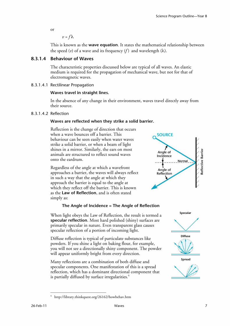
Reflection is the change of direction that occurs when a wave bounces off a barrier. This behaviour can be seen easily when water waves strike a solid barrier, or when a beam of light shines in a mirror. Similarly, the ears on most animals are structured to reflect sound waves onto the eardrum.
Regardless of the angle at which a wavefront approaches a barrier, the waves will always reflect in such a way that the angle at which they approach the barrier is equal to the angle at which they reflect off the barrier. This is known as the Law of Reflection, and is often stated simply as:
The Angle of Incidence = The Angle of Reflection
When light obeys the Law of Reflection, the result is termed a specular reflection. Most hard polished (shiny) surfaces are primarily specular in nature. Even transparent glass causes specular reflection of a portion of incoming light. Diffuse reflection is typical of particulate substances like powders. If you shine a light on baking flour, for example, you will not see a directionally shiny component. The powder will appear uniformly bright from every direction. Many reflections are a combination of both diffuse and specular components. One manifestation of this is a spread reflection, which has a dominant directional component that is partially diffused by surface irregularities.4
4 http://library.thinkquest.org/26162/howbehav.htm

Science Program Outline—Year 8
8 Waves 26-Feb-11
The discussion above pertains largely to the reflection of waves off of straight surfaces. But what if the surface is curved, perhaps in the shape of a parabola? What generalisations can be made for the reflection of waves off parabolic surfaces?
A parabola is a curve with a special characteristic—wave fronts or parallel rays striking a parabolic barrier are all reflected through a single point known as the focus. Similarly, if an energy source is placed at the focus of a parabola, waves will be reflected off the barrier in such a way that they exit as a planar wavefront or a collimated beam.
This, in fact, is true of any wave that strikes a parabolic reflector, with the result that wave energy is concentrated at the focus. This has many practical applications. Satellite dishes and radio telescopes receive TV and radio signals, directing their collective energy to a receiver located at the focus of the curved dish. Parabolic mirrors are also used to harness the heat from the sun, for applications ranging from simple solar cookers to the solar collectors used in some solar power generators. The reflector in a torch, car headlight or search light works in the opposite sense—it takes the light from a globe or electric arc and focuses it into a well-defined beam.
A parabolic reflector
The shape of a parabola will dictate the location of the
focus—as the parabola flattens out, the focus moves further
away from the reflector
8.3.1.4.3 Refraction
Waves are refracted when the properties of the medium in which they are travelling change.
Reflection involves a change in direction of waves when they bounce off a barrier. Refraction of waves involves a change in the direction of waves as they pass from one medium to another. Refraction, or bending of the path of the waves, is accompanied by a change in speed and wavelength of the waves.
We noted above that the speed of a wave was dependent upon the properties of the medium through which it passes. Accordingly, if the nature of the medium is changed, the speed of waves passing through the medium will also be changed. The most significant property of water that would affect the speed of waves travelling through it is its depth. Water waves travel fastest when the medium is the deepest. Thus, if water waves are passing from deep water into shallow water, they will slow down, and this decrease in speed is also accompanied by a decrease in wavelength. Thus, as water waves are transmitted from deep water into shallow water, the speed decreases, the wavelength decreases, and the direction changes.
Light behaves in a similar way. If we shine a beam of light into a glass prism, we notice that the beam is bent as it enters the prism. Not surprisingly, we will also note that the beam bends in the opposite sense as it leaves the prism. This latter fact may not be immediately obvious if the sides of the prism are not parallel, as in the case of a triangular prism.

Science Program Outline—Year 8
26-Feb-11 Waves 9
The degree to which light is refracted by a given medium is known as its Refractive Index. If θ1 is the Angle of Incidence in air and θ2 is the Angle of Refraction in a given medium, then the Refractive Index (RI) of the medium is defined by the equation:
RI = sinθ1 sinθ2
The more general form of this equation is known as Snell's Law, after the Dutch astronomer and mathematician Willebrord Snellius (1580–1626). Snell's Law states that the ratio of the sines of the angles of incidence and refraction is equal to the ration of velocities in the two media, or equivalently to the inverse ratio of the indices of refraction:
sinθ1 = v1 = n2
sinθ2 v2 n1
or
n1sin θ1 = n2sin θ2
When a wave travels from a medium of higher refractive index to one of lower refractive index, we can create a situation where the angle of refraction exceeds 90°—i.e. the wave cannot escape the medium of higher refractive index. This gives rise to a condition known as Total Internal Reflection, where a wave is reflected back into the 'incident' medium as illustrated below.
The Angle of Incidence, beyond which total internal reflection occurs, is known as the Critical Angle. The actual value of the Critical Angle is dependent on the media

Science Program Outline—Year 8
10 Waves 26-Feb-11
involved. For the water–air boundary, the Critical Angle is 48.6°, and for the crown glass5–water boundary, the critical angle is 61.0°.
Fibre optic technology is entirely dependent on the Total Internal Reflection phenomenon. When light of a particular frequency is directed into the glass core of an optical fibre, the light reflects off the walls of the glass and is thus transmitted along the length of the fibre. Lasers and light emitting diodes (LEDs) are used to generate light at the specific frequencies required for individual fibre optic applications.
Total Internal Reflection of light
in a glass (optical) fibre
8.3.1.4.4 Dispersion6
In a dispersive medium, the speed of a wave varies with its wavelength.
In optics, dispersion is a phenomenon that causes the separation of a wave into spectral components with different wavelengths, due to a dependence of the wave's speed on its wavelength. It is most often described in light waves, but it may happen to any kind of wave that interacts with a medium or can be confined to a waveguide (e.g. sound waves). Dispersion is sometimes called chromatic dispersion to emphasise its wavelength-dependent nature.
Chromatic dispersion
in a glass prism7
There are generally two sources of dispersion: material dispersion and waveguide dispersion. Material dispersion comes from a frequency-dependent response of a material to waves. For example, material dispersion leads to undesired chromatic aberration in a lens or the separation of colours in a prism. Waveguide dispersion occurs when the speed of a wave in a waveguide (such as an optical fibre) depends on its frequency for geometric reasons, independent of any frequency dependence of the materials from which it is constructed. This type of dispersion leads to signal degradation in telecommunications because the varying delay in arrival time between different components of a signal 'smears out' the signal in time.
8.3.1.4.5 Diffraction
Waves undergo diffraction when they pass through an opening or around a barrier.
There is a third, common mechanism by which waves change direction—they undergo diffraction as they pass through an opening or around a barrier in their path.
Diffraction of water waves can be observed in a harbour as waves bend around small boats and are found to disturb the water behind them. The same waves however are not affected by larger boats, because in this case their wavelength is smaller than the boat.
5 Note that there are many different kinds of glass, each with its own characteristic refractive index. 6 http://en.wikipedia.org/wiki/Dispersion_(optics) 7 http://en.wikipedia.org/wiki/image:Prism_rainbow_schema.png

Science Program Outline—Year 8
26-Feb-11 Waves 11
Diffraction can be demonstrated by placing small barriers and obstacles in a ripple tank and observing the path of the water waves as they encounter the obstacles. The waves are seen to pass around the barrier into the regions behind it; so that the water behind the barrier is disturbed. The degree of diffraction (the sharpness of the bending) increases with increasing wavelength. In fact, when the wavelength of the waves is smaller than the obstacle, no noticeable diffraction occurs.
Diffraction through a
narrow opening
8.3.1.4.6 Boundary Behaviour
When one medium ends, and another medium begins, the interface between the two media is referred to as a boundary and the behaviour of a wave (or pulse) when it strikes that boundary is referred to as boundary behaviour.
As we have already noted, a wave doesn't just stop when it reaches a boundary. Rather, the wave will exhibit certain behavioural characteristics when it encounters the end of a particular medium—specifically, there will usually be some reflection off the boundary and some transmission into the new medium. Indeed, reflection, refraction and diffraction are all boundary behaviours of waves associated with the bending of the path of the wave. We have also seen that refraction is accompanied by a change of both speed and wavelength. But what other effects does reflection, for example, have upon a wave? Does reflection of a wave effect the speed of the wave? Does reflection of a wave effect the wavelength and frequency of the wave? Does reflection of a wave effect the amplitude of the wave? Or does reflection affect other properties and characteristics of a wave's motion?
First consider a rope stretched from end to end, with one end securely attached to a pole and the other held in hand in order to introduce pulses into the medium. Because one end of the rope is attached to a pole, the last particle of the rope will be unable to move when a disturbance reaches it. This end of the rope is referred to as a fixed end. If a pulse is introduced at the other end of the rope, it will travel through the rope towards the other end of the medium. This pulse is called the incident pulse since it is incident towards (i.e. approaching) the boundary with the pole. When the incident pulse reaches the boundary, two things occur:
• A portion of the energy carried by the pulse is reflected and returns towards the left end of the rope. The disturbance that returns to the left after bouncing off the pole is known as the reflected pulse;
• A portion of the energy carried by the pulse is transmitted to the pole, causing the pole to vibrate.
Because the vibrations of the pole are not particularly obvious, the energy transmitted to it is not typically discussed. The focus of discussion is the reflected pulse. What characteristics and properties could describe its motion?
First the reflected pulse is inverted. That is, if a crest is incident towards a fixed end boundary, it will reflect and return as a trough. Similarly, if a trough is incident towards a fixed end boundary, it will reflect and return as a crest.

Science Program Outline—Year 8
12 Waves 26-Feb-11
Other notable characteristics of the reflected pulse include: • the speed of the reflected pulse is the same as the speed of the incident pulse • the wavelength of the reflected pulse is the same as the wavelength of the
incident pulse • the amplitude of the reflected pulse is less than the amplitude of the incident
pulse
Now consider what would happen if the end of the rope were free to move. Instead of being securely attached to a pole, suppose it is attached to a ring that is loosely fits around the pole. Because this end of the rope is no longer secured to the pole, the last particle of the rope will be able to move when a disturbance reaches it. This end of the rope is referred to as a free end.
Once more if a pulse is introduced at one end of the rope, it will travel through the rope towards the other. When the incident pulse reaches the end of the medium, the last particle of the rope can no longer interact with the first particle of the pole. Since the rope and pole are no longer attached and interconnected, they will slide past each other. The result is that the reflected pulse is not inverted. When a crest is incident upon a free end, it returns as a crest after reflection; and when a trough is incident upon a free end, it returns as a trough after reflection.
The above discussion of free end and fixed end reflection focuses upon the reflected pulse. As was mentioned, the transmitted portion of the pulse is difficult to observe when it is transmitted into a pole. But what if the original medium is attached to another rope with different properties? How could the reflected pulse and transmitted pulse be described in situations in which an incident pulse reflects off and transmits into a second medium?
Let's consider a thin rope attached to a thick rope, with each rope held at their respective opposite ends. Suppose then that a pulse is introduced into the end of the thin rope. In this case, there will be an incident pulse travelling in the less dense medium (thin rope) towards the boundary with a more dense medium (thick rope).
Upon reaching the boundary, the usual two behaviours will occur. • A portion of the energy carried by the incident pulse is reflected and returns
along the thin rope. The disturbance that returns after bouncing off the boundary is known as the reflected pulse;
• A portion of the energy carried by the incident pulse is transmitted into the thick rope. The disturbance that continues moving to the right is known as the transmitted pulse.
The reflected pulse is inverted in situations such as this. During the interaction between the two media at the boundary, the first particle of the more dense medium overpowers the smaller mass of the last particle of the less dense medium. This causes the crest to become a trough. The more dense medium on the other hand was at

Science Program Outline—Year 8
26-Feb-11 Waves 13
rest prior to the interaction. The first particle of this medium receives an upward pull (in the present example) when the incident pulse reaches the boundary. Since the more dense medium was originally at rest, an upward pull can do nothing but cause an upward displacement. For this reason, the transmitted pulse is not inverted. In fact transmitted pulses can never be inverted—since the particles in this medium are originally at rest, any change in their state of motion would be in the same direction as the displacement of the particles of the incident pulse.
Finally, let's consider a thick rope attached to a thin rope, with the incident pulse originating in the thick rope. If this is the case, there will be an incident pulse travelling in the more dense medium (thick rope) towards the boundary with a less dense medium (thin rope). Once more, there will be partial reflection and partial transmission at the boundary. The reflected pulse in this situation will not be inverted. Similarly, the transmitted pulse is not inverted (as is always the case). Since the incident pulse is in a heavier medium, when it reaches the boundary, the first particle of the less dense medium does not have sufficient mass to overpower the last particle of the more dense medium. The result is that a crest incident towards the boundary will reflect as a crest; and for the same reasons, a trough incident towards the boundary will reflect as a trough.
The boundary behaviour of waves can be summarised by the following principles: • The wave speed is always greatest in the least dense medium; • The wavelength is always greatest in the least dense medium; • The frequency of a wave is not altered by crossing a boundary; • The reflected pulse becomes inverted when a wave in a less dense medium is
heading towards a boundary with a more dense medium; • The amplitude of the incident pulse is always greater than the amplitude of the
reflected pulse.
Comparisons between the characteristics of the transmitted pulse and the reflected pulse lead to the following observations.
• The transmitted pulse (in the less dense medium) is travelling faster than the reflected pulse (in the more dense medium);
• The transmitted pulse (in the less dense medium) has a larger wavelength than the reflected pulse (in the more dense medium);
• The speed and the wavelength of the reflected pulse are the same as the speed and the wavelength of the incident pulse.
8.3.1.4.7 Interference
Interference patterns are formed when two sets of waves meet.
Wave interference is a phenomenon that occurs when two waves meet while travelling along or within the same medium.
Constructive interference is a type of interference that occurs at any location along or within the medium where the two interfering waves have a displacement in the same

Science Program Outline—Year 8
14 Waves 26-Feb-11
direction. In this case the resulting crests or troughs will be greater than those of either of the individual interfering waves.
Constructive interference Resultant wave
Destructive interference is a type of interference that occurs at any location along or within the medium where the two interfering waves have a displacement in the opposite direction. In this case the resulting crests or troughs will be smaller than those of either of the individual interfering waves.
Destructive interference Resultant wave
The task of determining the shape of the resultant wave demands that the Principle of Superposition be applied.
The Principle of Superposition can be stated as follows: When two waves interfere, the resulting displacement of the medium at any location is the algebraic sum of the displacements of the individual waves at that same location.
Superposition Constructive/Destructive Interference
Resultant wave

Science Program Outline—Year 8
26-Feb-11 Waves 15
Interestingly, the meeting of two waves within a medium does not alter the individual waves or even cause them to deviate from their individual paths. This only becomes an astounding behaviour when it is compared to what happens when two billiard balls meet or two football players meet. Billiard balls might crash and bounce off each other and football players might crash and come to a stop. Yet waves meet, produce a net resulting shape of the medium, and then continue on doing what they were doing before the interference.
The interaction of sets of waves can generate very complex interference patterns.
Typical interference pattern generated by two interacting point source wave sequences
8.3.1.5 The Doppler Effect
Suppose that there is a happy bug, in the centre of a circular water puddle, who is periodically shaking its legs, producing disturbances that travel through the water. If these disturbances originate at a point, they would travel outward from that point in all directions. Since each disturbance is travelling in the same medium, they would all travel in every direction at the same speed. The pattern produced by the bug's shaking would be a series of concentric circles as illustrated on the left below. These circles would strike the edges of the water puddle at the same rate. An observer at point A (the left edge of the puddle) would observe the disturbances to strike the puddle's edge at the same frequency that would be observed by an observer at point B (at the right edge of the puddle). In fact, the frequency at which disturbances reach the edge of the puddle would be the same as the frequency at which the bug produces the disturbances. If the bug produces disturbances at a frequency of 2 per second, then each observer would observe them approaching at a frequency of 2 per second.
Stationary bug Bug moving toward B
Now suppose that our bug is moving to the right across the puddle of water and producing disturbances at the same frequency of 2 disturbances per second. Since the bug is moving towards the right, each consecutive disturbance originates from a position that is closer to observer B and farther from observer A, as illustrated on the right above. As a result, each consecutive disturbance has a shorter distance to travel before reaching observer B and thus takes less time to reach observer B. Thus, observer B notes that the frequency of arrival of the disturbances is higher than the frequency at which disturbances are produced. On the other hand, each disturbance has a further distance to travel before reaching observer A. For this reason, observer B observes a frequency of arrival which is less than the frequency at which the disturbances are

Science Program Outline—Year 8
16 Waves 26-Feb-11
produced. The net effect of the motion of the bug (the source of waves) is that the observer towards whom the bug is moving observes a frequency which is higher than 2 disturbances/second; and the observer away from whom the bug is moving observes a frequency which is less than 2 disturbances/second. This effect is known as the Doppler Effect, after the Austrian mathematician and physicist Christian Doppler (1803–1853) who first explained the phenomenon.
The Doppler Effect is observed whenever the source of waves is moving with respect to an observer. The Doppler Effect can be described as the effect produced by a moving source of waves in which there is an apparent upward shift in frequency for observers towards whom the source is approaching and an apparent downward shift in frequency for observers from whom the source is receding. It is important to note that the effect is not the result of an actual change in the frequency of the source. Using the example above, the bug is still producing disturbances at a rate of 2 per second; it just appears to the observer whom the bug is approaching that the disturbances are being produced at a frequency greater than 2 disturbances/second. The effect is only observed because the distance between observer B and the bug is decreasing and the distance between observer A and the bug is increasing.
The Doppler effect can be observed for any type of wave—water wave, sound wave, light wave, etc. We are most familiar with the Doppler effect because of our experiences with sound waves. Perhaps you recall an instance in which a police car or emergency vehicle was travelling towards you on the highway. As the car approached with its siren blasting, the pitch of the siren sound (a measure of the siren's frequency) was high; and then suddenly after the car passed by, the pitch of the siren sound was low. That was the Doppler effect—an apparent shift in frequency for a sound wave produced by a moving source.
Illustration of the Doppler Effect—The changing pitch of a passing siren8
The Doppler effect is of particular interest to astronomers who use the information about the shift in frequency of electromagnetic waves produced by moving stars in our galaxy and beyond in order to derive information about those stars and galaxies. The belief that the universe is expanding is based in part upon observations of electromagnetic waves emitted by stars in distant galaxies. Furthermore, specific information about stars within galaxies can be determined by application of the Doppler effect. Galaxies are clusters of stars that typically rotate about some centre of mass point. Electromagnetic radiation emitted by such stars in a distant galaxy would
8 Illustration by Jeremy Kemp
http://en.wikipedia.org/wiki/Image:Doppler-effect-two-police-cars-diagram.png

Science Program Outline—Year 8
26-Feb-11 Waves 17
appear to be shifted downward in frequency (a red shift) if the star is rotating in its cluster in a direction which is away from the Earth. On the other hand, there is an upward shift in frequency (a blue shift) of such observed radiation if the star is rotating in a direction that is towards the Earth.
8.3.1.5.1 Shock Waves9
The Doppler effect is observed whenever the speed of the source is moving slower than the speed of the waves. But if the source actually moves at the same speed as or faster than the wave itself can move, a different phenomenon is observed. If a source of sound moves at the same speed as the sound waves it produces, then the source will always be at the leading edge of the waves. If a source of sound moves faster than sound, the source will always be ahead of the waves that it produces. A sonic boom occurs as a result of the piling up of compressional wavefronts along the conical edge of the resulting wave pattern. These compressional wavefronts interfere with each other constructively to produce a very high pressure zone. Since every compression is followed by a rarefaction, the high pressure zone will be immediately followed by a low pressure zone, creating a very loud noise.
Compression waves generated by aircraft in flight.
Note that the circular wave fronts are simply 2D representations of the actual spherical wave front and that the 3D shock wave envelope is actually conical.
The term sonic boom is commonly used to refer to the shocks caused by the supersonic flight of military aircraft or passenger transports such as Concorde (Mach 2.03, no longer in service) and the Space Shuttle (up to Mach 27). As an object passes through the air, it creates a series of pressure waves in front of it and behind it, similar to the bow and stern waves created by a boat. These waves travel at the speed of sound, and as the speed of the aircraft increases the waves are forced together, or compressed, because they cannot 'get out of the way' of each other, eventually merging into a single shock wave at the speed of sound. This critical speed is known as Mach 1, approximately 1,225 kilometres per hour (761 mph) at sea level.
9 http://en.wikipedia.org/wiki/Shock_wave
http://en.wikipedia.org/wiki/Sonic_boom

Science Program Outline—Year 8
18 Waves 26-Feb-11
In smooth flight, the shock wave starts at the nose of the aircraft and ends at the tail. There is a sudden rise in pressure at the nose, decreasing steadily to a negative pressure at the tail, where it suddenly returns to normal. This leads to a distinctive 'double boom' from supersonic aircraft. Since the boom is being generated continually as long as the aircraft is supersonic, it traces out a path on the ground following the aircraft's flight path, known as the boom carpet.
The sonic shock wave is usually invisible. In this case, however, the effects of a
shock wave extending behind a low-flying jet over the ocean are clearly visible. As water vapour in the air was compressed by the shock wave, it condensed into
droplets and formed a conical cloud behind the tail of the jet.10
Sonic booms generate enormous amounts of sound energy, sounding much like an explosion. Thunder is a type of natural sonic boom, created by the rapid heating and expansion of air associated with an electrical discharge (lightning).
A similar tunnel boom can result when a high-speed train, such as the Japanese Shinkansen or the French TGV, passes through a tunnel. In order to reduce the sonic boom effect, a special shape of the train and a widened opening of the tunnel entrance are necessary. When a high-speed train enters a tunnel, the sonic boom effect occurs at the tunnel exit. In contrast to the (super)sonic boom of an aircraft, this 'tunnel boom' is caused by a rapid change of subsonic flow (from the sudden narrowing of the surrounding space) rather than by a shock wave. Close to the tunnel exit this phenomenon can cause disturbances to residents.
8.3.1.6 Standing Waves
8.3.1.6.1 Travelling Waves vs. Standing Waves
A mechanical wave is a disturbance, created by a vibrating object, which travels through a medium from one location to another, transporting energy. This type of wave pattern, which moves through a medium, is sometimes referred to as a travelling wave. Travelling waves are observed when a wave is not confined within a medium. The most commonly observed travelling wave is an ocean wave.
If, however, a wave is introduced into an elastic chord whose far end is fixed, it will be confined to the length of the chord. The wave will quickly reach the end of the chord, be reflected and travel back in the opposite direction. The reflected portion of the wave 10 Photograph by Ensign John Gray, USS Constellation, US Navy
http://apod.nasa.gov/apod/image/0102/sonicboomplane_navy_big.jpg
Science Program Outline—Year 8
26-Feb-11 Waves 19
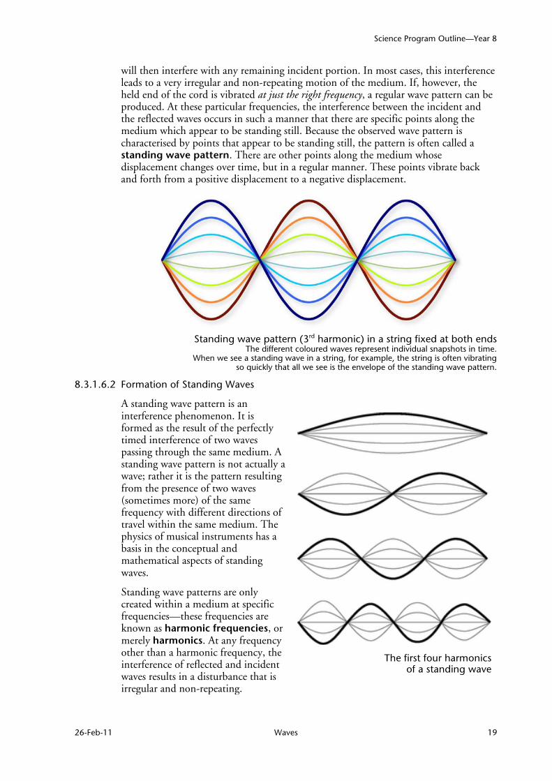
will then interfere with any remaining incident portion. In most cases, this interference leads to a very irregular and non-repeating motion of the medium. If, however, the held end of the cord is vibrated at just the right frequency, a regular wave pattern can be produced. At these particular frequencies, the interference between the incident and the reflected waves occurs in such a manner that there are specific points along the medium which appear to be standing still. Because the observed wave pattern is characterised by points that appear to be standing still, the pattern is often called a standing wave pattern. There are other points along the medium whose displacement changes over time, but in a regular manner. These points vibrate back and forth from a positive displacement to a negative displacement.
Standing wave pattern (3rd harmonic) in a string fixed at both ends
The different coloured waves represent individual snapshots in time. When we see a standing wave in a string, for example, the string is often vibrating
so quickly that all we see is the envelope of the standing wave pattern.
8.3.1.6.2 Formation of Standing Waves
A standing wave pattern is an interference phenomenon. It is formed as the result of the perfectly timed interference of two waves passing through the same medium. A standing wave pattern is not actually a wave; rather it is the pattern resulting from the presence of two waves (sometimes more) of the same frequency with different directions of travel within the same medium. The physics of musical instruments has a basis in the conceptual and mathematical aspects of standing waves.
Standing wave patterns are only created within a medium at specific frequencies—these frequencies are known as harmonic frequencies, or merely harmonics. At any frequency other than a harmonic frequency, the interference of reflected and incident waves results in a disturbance that is irregular and non-repeating.
The first four harmonics
of a standing wave
Science Program Outline—Year 8
20 Waves 26-Feb-11
The harmonics of any particular medium are simply integral multiples of the fundamental frequency of that medium. In a vibrating string, the fundamental frequency is that frequency which corresponds to a wavelength that is twice the length of the medium. The first four harmonics of a vibrating string are illustrated below.
If L is the length of a vibrating string, then the wavelength corresponding to the fundamental frequency is given simply by the equation:
λ = 2L
Using the Wave Equation from Section 8.3.1.3.2, the fundamental frequency (f ) is given by the equation:
f = v = v λ 2L
where v is the speed of waves on the string.
The harmonic frequencies, also known as the harmonic series, for standing waves on a vibrating string are then given by the equation:
fn = n v n = 1, 2, 3, 4,... 2L
This same equation can be used to determine the harmonic series for standing waves in an open column of air, as exists in the brass and woodwind instruments, and the open pipes of an organ. The situation is slightly different if one end of the pipe is closed, as is the case with some organ pipes, where only the odd harmonics are present.
8.3.1.6.3 Nodes and Anti-nodes
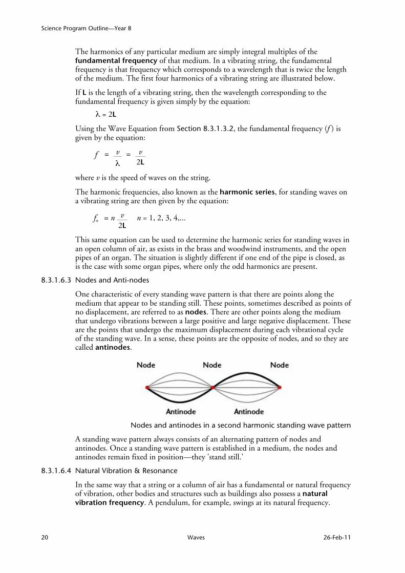
One characteristic of every standing wave pattern is that there are points along the medium that appear to be standing still. These points, sometimes described as points of no displacement, are referred to as nodes. There are other points along the medium that undergo vibrations between a large positive and large negative displacement. These are the points that undergo the maximum displacement during each vibrational cycle of the standing wave. In a sense, these points are the opposite of nodes, and so they are called antinodes.
Nodes and antinodes in a second harmonic standing wave pattern
A standing wave pattern always consists of an alternating pattern of nodes and antinodes. Once a standing wave pattern is established in a medium, the nodes and antinodes remain fixed in position—they 'stand still.'
8.3.1.6.4 Natural Vibration & Resonance
In the same way that a string or a column of air has a fundamental or natural frequency of vibration, other bodies and structures such as buildings also possess a natural vibration frequency. A pendulum, for example, swings at its natural frequency.

Science Program Outline—Year 8
26-Feb-11 Waves 21
When a body is vibrating at its natural frequency, energy can be transferred to another body that has the same natural frequency, giving rise to sympathetic vibrations in the second body. This phenomenon is called resonance.
Consider a child on a swing. It is an easy task to increase the amplitude of oscillation of the swing if energy is applied in time with the natural frequency of the swing. If we try to push the swing in a manner that does not coincide with the natural 'vibration' of the swing—when the swing was coming towards us, for example, or just pushing at a speed other than that of the swing—our efforts will not be nearly so effective.
Natural resonance is best known for its role in the creation of music. Great care is taken in the crafting of fine instruments, to identify the characteristics of the materials used in, and structural details of, the various components. The resulting interactions between natural resonances in an instrument contribute greatly to its unique qualities.
The best known destructive examples of natural resonance occur during earthquakes, when the frequency of earthquake waves matches the natural or one of the resonant frequencies of a building. When this happens, the energy of the earthquake can be transferred to the building with disastrous consequences.
The failure of the Tacoma Narrows bridge on November 7, 1940, is often presented as a classic case of structural failure due to natural resonance. More recent engineering analysis11, however, suggests that the failure was actually the result of an aerodynamically induced condition (the shape of the bridge was much like that of an aircraft wing) known as self-excitation, or negative damping.
11 "Resonance, Tacoma Narrows bridge failure, and undergraduate physics textbooks", Billah, Y. and
Scanlan, B., Am. J. Phys. 59 (2), February 1991

Science Program Outline—Year 8
22 Waves 26-Feb-11
References
The Physics Classroom (http://www.physicsclassroom.com/Default2.html)
How Light Behaves (http://library.thinkquest.org/26162/howbehav.htm)
A brief history of the Tacoma Narrows bridge, and a URL for a video clip of the final stages of the collapse of the original bridge on November 7, 1940 can be found at http://en.wikipedia.org/wiki/Tacoma_Narrows_Bridge