850 725 600 500 400 300 250 - milacron specifications reflect average values based on typical...
TRANSCRIPT

S P E C I F I C A T I O N S
H Y D R AU L I C
I N J E C T I O N
M O L D I N G
M AC H I N E S
250300400500600725850
All specifications reflect average values based on typical machine layouts. Actual figures will vary depending on final machine configuration. If yourequire more specific data, consult a certified installation print for your particular machine. Performance specifications are based on theoretical data.Due to continual improvements, specifications are subject to change without notice.
Mi lacron Inc. , Plast ics Technologies Group4165 Halfacre Road, Batavia, OH 45103 Phone 513/536-2352 / Fax 513/536-2624 / www.milacron.com
CINCINNATI MILACRON, MAGNA and the Globe Graphic are trademarks of Mi lacron Inc.
© 1999 Mi lacron Inc. Pr inted in U.S.A. 3/99 PM783 10M
We’re your single-source productivity supplier
n All-Electric Injection Molding Machines
n High-Technology Injection Molding Machines
n Vertical Insert Injection Molding Machines
n Multi-Color/Material Injection Molding Machines
n Consumer and Industrial Blow Molding Machines
n D-M-E Mold Bases and Supplies
n Independent Service Provider Network
n Rebuilt and Retrofitted Machines
n Peripheral Auxiliary Equipment
n Service Parts Distribution Center
n Conical Twin Screw Extrusion Systems
n Parallel Twin Screw Extrusion Systems
n New and Rebuilt Extrusion Screws
n Single Screw Extrusion Systems
n Sheet Extrusion Systems

H Y D R A U L I C S
• Full time 5 micron oil filtration with indicator• Advanced proportional hydraulics for increased energy
efficiency, quieter operation, rapid response• Ergonomic hydraulic layout for easier, quicker access
to all components• Increased use of flexible hose for quieter operation
and less leakage• Seal-Lock fittings for dependability,
reduced leakage• Access cover to prefill cylinder for ease
of maintenance• Manifold placement for greatest control
C O N T R O L
• Closed-loop injection velocity and pressure control• Multi-microprocessors with diagnostics and audible
alarms• 9.5” backlit LCD screen• Internal data storage for 40 molds• Process monitoring displays and alarms• Complete digital set-up and display• Non-contact type position transducers• Closed-loop oil temperature control
with alarm• Feed throat temperature readout• Barrel high/low temperature readout• Alarms logged with time/date• Clogged filter alarm• Control cabinet temperature monitor
with alarm• Low lube alarm• S.P.C. X-bar and R-charts• Host computer interface• Production monitor• Digital valve driver• Oil pre-heat sequence• Overall cycle time• Resettable cycle counter• Parallel printer interface
• Split screens• Configurable quickset screens
I N J E C T I O N
• 5-stage injection pressure; (1) injection high, (5) pack, (5) hold
• 5-stage profiled injection velocities• 5-stage back pressure control• 5-stage screw rpm• Dual torque/rpm piston type extruder motor• PID temperature control of nozzle
and barrel• Extruder start time delay• Slide shutoff on hopper• Cold screw start protection• Injection transfer on position, hydraulic pressure,
or time• A-B-C screw and barrel combinations• 27,500 psi injection pressure on
“A” barrels• Injection unit swivel• Hopper discharge chute• Ball check or slider screw tip
A V A I L A B L E O P T I O N S
• Sprue break• Hopper magnet• 16 sequence hydraulic core pull• Leveling pads• 230 volt connecting electrics• Hardened injection screws/bimetalic barrels• Mixing screws• Robot interface• Peripheral equipment interface• Increased injection rate• Power factor capacitors• Water manifolds• Air eject• Cavity pressure transfer
2
H Y D R A U L I C I N J E C T I O N M O L D I N G M A C H I N E S
Next generation hydraulic injection molding per formance machine from Cincinnati Milacron.
D E S I G N A D V A N T A G E S
• Fully metricized, a truly global machine• Energy efficient variable volume pump with
proportional hydraulics• Integrated hydraulics for quieter operation• Interchangeable screw/barrel combinations for full
process versatility• Efficient, precise twin cylinder injection units• Easy-to-use nozzle alignment devices• Twin guide rod injection unit carriage to maintain
nozzle alignment• Controlled-stress tie rods• Modular low profile I-beam base design• Generous mold space for production versatility• Rapid traverse cylinders• Twin pull-in cylinders• Integrated machine operator panel with direct menu
access keys
S T A N D A R D F E A T U R E S
C L A M P
• 2-stage clamp close velocity (1) selectable• 3-stage clamp open velocity (2) selectable• Rigid cast platens• Adjustable moving platen supports• Pulsating hydraulic eject• Ejector forward dwell timer• Self adjusting, ratchet type, die safety jam bar• Ejector retract override for faster cycles• SPI knockout pattern with drilled ejector plate• Low pressure mold protect with
try-again circuit• Automatic tie rod and skate lubrication with
independent frequency adjustment• Prefill designed for fast trouble-free operation
1
4
Magna 400
INJECTION SPECIFICATIONS A B C A B C A B C A B CG.P. Polystyrene (Theoretical) oz. 21 29 34 41 54 68 41 54 68 85 105 127Displacement in3 37.7 52.6 61.1 75.2 98.2 124.2 75.2 98.2 124.2 155.3 191.7 232.0Injection Pressure, Max. kpsi 27.5 19.7 16.9 27.5 21.0 16.6 27.5 21.0 16.6 27.5 22.2 18.4Injection Rate in3/sec 20 28 32 21 28 36 29 38 4 28 34 41Injection Screw Stroke in 10.24 10.24 10.24 12.60 12.60 12.60 12.60 12.60 12.60 15.75 15.75 15.75Screw Diameter in 2.17 2.56 2.76 2.76 3.15 3.54 2.76 3.15 3.54 3.54 3.94 4.33Screw L/D Ratio 23.6:1 20:1 18.6:1 22.9:1 20:1 17.8:1 22.9:1 20:1 17.8:1 22.2:1 20:1 18.2:1Nozzle Holding Force tons 3 3 3 3 3 3 4.09 4.09 4.09 4.09 4.09 4.09
Screw PerformanceLow Torque Screw Speed, Max rpm 329 rpm @ 2500 psi 165 rpm @ 2500 psi 222 rpm @ 2500 psi 119 rpm @ 2500 psi Low Torque at Screw in-lb 15,900 in-lb @ 2500 psi 31,800 in-lb @ 2500 psi 31,800 in-lb @ 2500 psi 59,700 in-lb @ 2500 psiHi Torque Screw Speed, Max rpm 219 rpm @ 2500 psi 110 rpm @ 2500 psi 148 rpm @ 2500 psi 77 rpm @ 2500 psi
Hi Torque at Screw in-lb 23,900 in-lb @ 2500 psi 47,700 in-lb @ 2500 psi 47,700 in-lb @ 2500 psi 91,500 in-lb @ 2500 psi
Barrel Heat ControlNumber of Pyrometers (Barrel/Nozzle) 3/1 3/1 3/1 3/1Total Heat Capacity kw 31 31 31 57CLAMP SPECIFICATIONS
Clamp Force tons 400 500Clamp Opening Force tons 22.8 34.7Clamp Stroke in 37.0 40.2Clamp Speed in/sec 21.28 closed / 30.0 open 19.34 closed / 30.0 open Dry cycle time (typical) ** sec 4.0 5.0Maximum Daylight in 51.2 55.1
With Spacer in 44.7 47.7Minimum Mold Thickness in 14.2 15.0
With Spacer in 7.7 7.5Platen Size (HxV) in 40.9 x 40.9 48.0 x 48.0Distance between Tie Rods (HxV) in 29.1 x 29.1 34.3 x 34.3Tie Rod Diameter in 4.92 5.51Ejector Stroke (Max) in 5.83 5.83 Ejector Force tons 8.3 12.5
INJECTION CAPACITY A B C A B C A B C A B CDimensions, OverallLength (11,13,16 oz) in 283.6 283.6 333.8 366.1 Top of Hopper (11,13,16 oz) in 90.5 105.6 102.7 105.6 Top of Feedthroat (11,13,16 oz) in 65.3 69.8 66.9 70.0Centerline Height in 57.2 57.2Width in 83.7 100.4Height (No leveling pads) in 101 106.5Shipping Weight (Est.) lbs 45,950 75,300
Electric and HydraulicMachine Hyd. System
Pressure Max psi 2,784 2,813Hyd. Pump Cap. @100 psi (Total) gpm 75 96Electric Motor hp 60 75
Total Oil Reservoir Capacity gal 222 344
Water RequirementsHeat Exchanger * gpm 20 18
Magna 500EnglishMagna 250
3
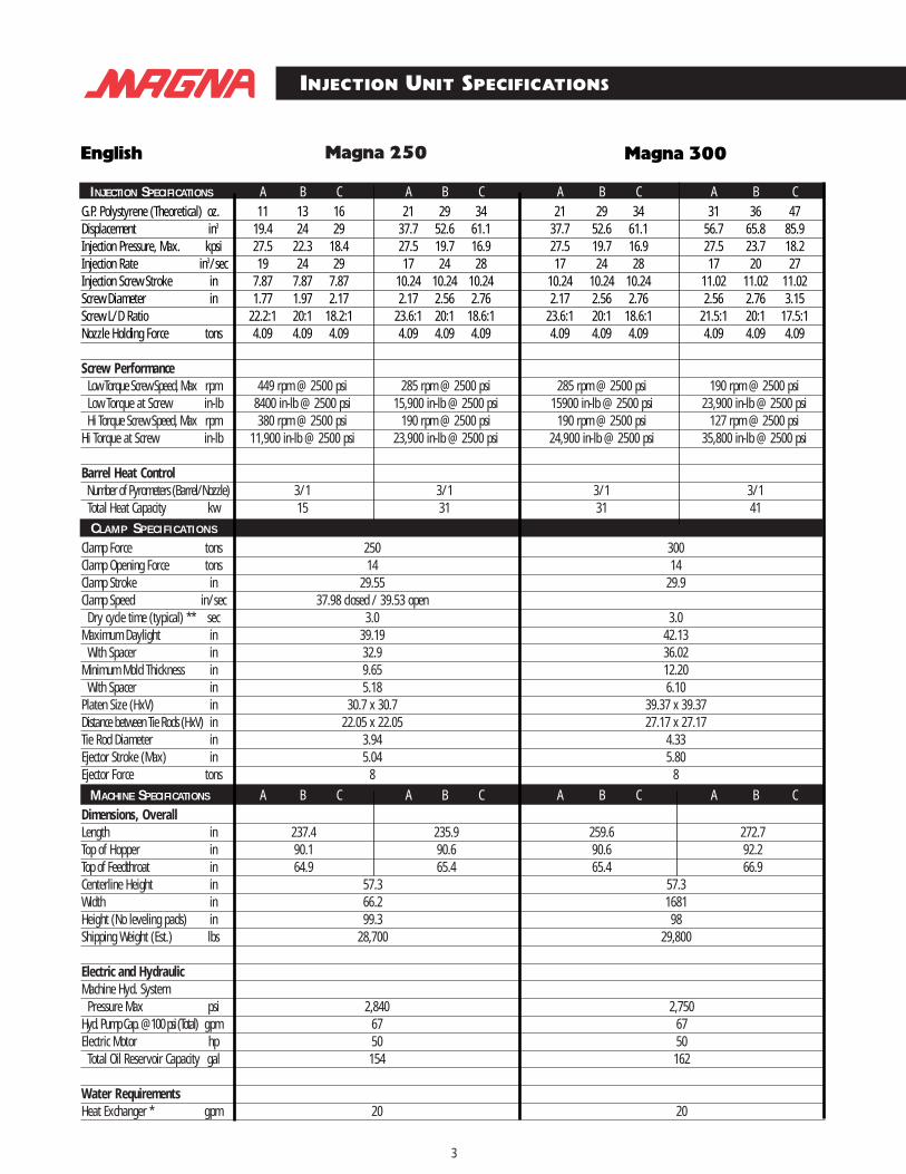
INJECTION SPECIFICATIONS A B C A B C A B C A B CG.P. Polystyrene (Theoretical) oz. 11 13 16 21 29 34 21 29 34 31 36 47Displacement in3 19.4 24 29 37.7 52.6 61.1 37.7 52.6 61.1 56.7 65.8 85.9Injection Pressure, Max. kpsi 27.5 22.3 18.4 27.5 19.7 16.9 27.5 19.7 16.9 27.5 23.7 18.2Injection Rate in3/sec 19 24 29 17 24 28 17 24 28 17 20 27Injection Screw Stroke in 7.87 7.87 7.87 10.24 10.24 10.24 10.24 10.24 10.24 11.02 11.02 11.02Screw Diameter in 1.77 1.97 2.17 2.17 2.56 2.76 2.17 2.56 2.76 2.56 2.76 3.15Screw L/D Ratio 22.2:1 20:1 18.2:1 23.6:1 20:1 18.6:1 23.6:1 20:1 18.6:1 21.5:1 20:1 17.5:1Nozzle Holding Force tons 4.09 4.09 4.09 4.09 4.09 4.09 4.09 4.09 4.09 4.09 4.09 4.09
Screw PerformanceLow Torque Screw Speed, Max rpm 449 rpm @ 2500 psi 285 rpm @ 2500 psi 285 rpm @ 2500 psi 190 rpm @ 2500 psiLow Torque at Screw in-lb 8400 in-lb @ 2500 psi 15,900 in-lb @ 2500 psi 15900 in-lb @ 2500 psi 23,900 in-lb @ 2500 psiHi Torque Screw Speed, Max rpm 380 rpm @ 2500 psi 190 rpm @ 2500 psi 190 rpm @ 2500 psi 127 rpm @ 2500 psi
Hi Torque at Screw in-lb 11,900 in-lb @ 2500 psi 23,900 in-lb @ 2500 psi 24,900 in-lb @ 2500 psi 35,800 in-lb @ 2500 psi
Barrel Heat ControlNumber of Pyrometers (Barrel/Nozzle) 3/1 3/1 3/1 3/1Total Heat Capacity kw 15 31 31 41CLAMP SPECIFICATIONS
Clamp Force tons 250 300Clamp Opening Force tons 14 14Clamp Stroke in 29.55 29.9Clamp Speed in/sec 37.98 closed / 39.53 open
Dry cycle time (typical) ** sec 3.0 3.0Maximum Daylight in 39.19 42.13
With Spacer in 32.9 36.02Minimum Mold Thickness in 9.65 12.20
With Spacer in 5.18 6.10Platen Size (HxV) in 30.7 x 30.7 39.37 x 39.37Distance between Tie Rods (HxV) in 22.05 x 22.05 27.17 x 27.17Tie Rod Diameter in 3.94 4.33Ejector Stroke (Max) in 5.04 5.80Ejector Force tons 8 8
MACHINE SPECIFICATIONS A B C A B C A B C A B CDimensions, OverallLength in 237.4 235.9 259.6 272.7 Top of Hopper in 90.1 90.6 90.6 92.2 Top of Feedthroat in 64.9 65.4 65.4 66.9Centerline Height in 57.3 57.3Width in 66.2 1681Height (No leveling pads) in 99.3 98Shipping Weight (Est.) lbs 28,700 29,800
Electric and HydraulicMachine Hyd. System
Pressure Max psi 2,840 2,750Hyd. Pump Cap. @100 psi (Total) gpm 67 67Electric Motor hp 50 50
Total Oil Reservoir Capacity gal 154 162
Water RequirementsHeat Exchanger * gpm 20 20
INJECTION UNIT SPECIFICATIONS
Magna 300English

4
Magna 400
INJECTION SPECIFICATIONS A B C A B C A B C A B CG.P. Polystyrene (Theoretical) oz. 21 29 34 41 54 68 41 54 68 85 105 127Displacement in3 37.7 52.6 61.1 75.2 98.2 124.2 75.2 98.2 124.2 155.3 191.7 232.0Injection Pressure, Max. kpsi 27.5 19.7 16.9 27.5 21.0 16.6 27.5 21.0 16.6 27.5 22.2 18.4Injection Rate in3/sec 20 28 32 21 28 36 29 38 4 28 34 41Injection Screw Stroke in 10.24 10.24 10.24 12.60 12.60 12.60 12.60 12.60 12.60 15.75 15.75 15.75Screw Diameter in 2.17 2.56 2.76 2.76 3.15 3.54 2.76 3.15 3.54 3.54 3.94 4.33Screw L/D Ratio 23.6:1 20:1 18.6:1 22.9:1 20:1 17.8:1 22.9:1 20:1 17.8:1 22.2:1 20:1 18.2:1Nozzle Holding Force tons 3 3 3 3 3 3 4.09 4.09 4.09 4.09 4.09 4.09
Screw PerformanceLow Torque Screw Speed, Max rpm 329 rpm @ 2500 psi 165 rpm @ 2500 psi 222 rpm @ 2500 psi 119 rpm @ 2500 psi Low Torque at Screw in-lb 15,900 in-lb @ 2500 psi 31,800 in-lb @ 2500 psi 31,800 in-lb @ 2500 psi 59,700 in-lb @ 2500 psiHi Torque Screw Speed, Max rpm 219 rpm @ 2500 psi 110 rpm @ 2500 psi 148 rpm @ 2500 psi 77 rpm @ 2500 psi
Hi Torque at Screw in-lb 23,900 in-lb @ 2500 psi 47,700 in-lb @ 2500 psi 47,700 in-lb @ 2500 psi 91,500 in-lb @ 2500 psi
Barrel Heat ControlNumber of Pyrometers (Barrel/Nozzle) 3/1 3/1 3/1 3/1Total Heat Capacity kw 31 31 31 57CLAMP SPECIFICATIONS
Clamp Force tons 400 500Clamp Opening Force tons 22.8 34.7Clamp Stroke in 37.0 40.2Clamp Speed in/sec 21.28 closed / 30.0 open 19.34 closed / 30.0 open Dry cycle time (typical) ** sec 4.0 5.0Maximum Daylight in 51.2 55.1
With Spacer in 44.7 47.7Minimum Mold Thickness in 14.2 15.0
With Spacer in 7.7 7.5Platen Size (HxV) in 40.9 x 40.9 48.0 x 48.0Distance between Tie Rods (HxV) in 29.1 x 29.1 34.3 x 34.3Tie Rod Diameter in 4.92 5.51Ejector Stroke (Max) in 5.83 5.83 Ejector Force tons 8.3 12.5
INJECTION CAPACITY A B C A B C A B C A B CDimensions, OverallLength (11,13,16 oz) in 283.6 283.6 333.8 366.1 Top of Hopper (11,13,16 oz) in 90.5 105.6 102.7 105.6 Top of Feedthroat (11,13,16 oz) in 65.3 69.8 66.9 70.0Centerline Height in 57.2 57.2Width in 83.7 100.4Height (No leveling pads) in 101 106.5Shipping Weight (Est.) lbs 45,950 75,300
Electric and HydraulicMachine Hyd. System
Pressure Max psi 2,784 2,813Hyd. Pump Cap. @100 psi (Total) gpm 75 96Electric Motor hp 60 75
Total Oil Reservoir Capacity gal 222 344
Water RequirementsHeat Exchanger * gpm 20 18
Magna 500EnglishMagna 250
3
INJECTION SPECIFICATIONS A B C A B C A B C A B CG.P. Polystyrene (Theoretical) oz. 11 13 16 21 29 34 21 29 34 31 36 47Displacement in3 19.4 24 29 37.7 52.6 61.1 37.7 52.6 61.1 56.7 65.8 85.9Injection Pressure, Max. kpsi 27.5 22.3 18.4 27.5 19.7 16.9 27.5 19.7 16.9 27.5 23.7 18.2Injection Rate in3/sec 19 24 29 17 24 28 17 24 28 17 20 27Injection Screw Stroke in 7.87 7.87 7.87 10.24 10.24 10.24 10.24 10.24 10.24 11.02 11.02 11.02Screw Diameter in 1.77 1.97 2.17 2.17 2.56 2.76 2.17 2.56 2.76 2.56 2.76 3.15Screw L/D Ratio 22.2:1 20:1 18.2:1 23.6:1 20:1 18.6:1 23.6:1 20:1 18.6:1 21.5:1 20:1 17.5:1Nozzle Holding Force tons 4.09 4.09 4.09 4.09 4.09 4.09 4.09 4.09 4.09 4.09 4.09 4.09
Screw PerformanceLow Torque Screw Speed, Max rpm 449 rpm @ 2500 psi 285 rpm @ 2500 psi 285 rpm @ 2500 psi 190 rpm @ 2500 psiLow Torque at Screw in-lb 8400 in-lb @ 2500 psi 15,900 in-lb @ 2500 psi 15900 in-lb @ 2500 psi 23,900 in-lb @ 2500 psiHi Torque Screw Speed, Max rpm 380 rpm @ 2500 psi 190 rpm @ 2500 psi 190 rpm @ 2500 psi 127 rpm @ 2500 psi
Hi Torque at Screw in-lb 11,900 in-lb @ 2500 psi 23,900 in-lb @ 2500 psi 24,900 in-lb @ 2500 psi 35,800 in-lb @ 2500 psi
Barrel Heat ControlNumber of Pyrometers (Barrel/Nozzle) 3/1 3/1 3/1 3/1Total Heat Capacity kw 15 31 31 41CLAMP SPECIFICATIONS
Clamp Force tons 250 300Clamp Opening Force tons 14 14Clamp Stroke in 29.55 29.9Clamp Speed in/sec 37.98 closed / 39.53 open
Dry cycle time (typical) ** sec 3.0 3.0Maximum Daylight in 39.19 42.13
With Spacer in 32.9 36.02Minimum Mold Thickness in 9.65 12.20
With Spacer in 5.18 6.10Platen Size (HxV) in 30.7 x 30.7 39.37 x 39.37Distance between Tie Rods (HxV) in 22.05 x 22.05 27.17 x 27.17Tie Rod Diameter in 3.94 4.33Ejector Stroke (Max) in 5.04 5.80Ejector Force tons 8 8
MACHINE SPECIFICATIONS A B C A B C A B C A B CDimensions, OverallLength in 237.4 235.9 259.6 272.7 Top of Hopper in 90.1 90.6 90.6 92.2 Top of Feedthroat in 64.9 65.4 65.4 66.9Centerline Height in 57.3 57.3Width in 66.2 1681Height (No leveling pads) in 99.3 98Shipping Weight (Est.) lbs 28,700 29,800
Electric and HydraulicMachine Hyd. System
Pressure Max psi 2,840 2,750Hyd. Pump Cap. @100 psi (Total) gpm 67 67Electric Motor hp 50 50
Total Oil Reservoir Capacity gal 154 162
Water RequirementsHeat Exchanger * gpm 20 20
INJECTION UNIT SPECIFICATIONS
Magna 300English

6
Magna 850
INJECTION SPECIFICATIONS A B C A B CG.P. Polystyrene (Theoretical)oz. 60 77 95 116 140 181Displacement in3 110.4 139.8 172.5 210.9 255.2 329.5Injection Pressure, Max. kpsi 27.5 21.7 17.6 27.5 22.7 17.6Injection Rate in3/sec 40 51 63 41 50 64Injection Screw Stroke in 14.17 14.17 14.17 17.32 17.32 17.32Screw Diameter in 3.15 3.54 3.94 3.94 4.33 4.92Screw L/D Ratio 22.5:1 20:1 18:1 22:1 20:1 17.6:1Nozzle Holding Force tons 4.09 4.09 4.09 4.09 4.09 4.09
Screw PerformanceLow Torque Screw Speed, Max rpm 221 rpm @ 2500 psi 122 rpm @ 2500 psiLow Torque at Screw in-lb 43,800 in-lb @ 2500 psi 79,600 in-lb @ 2500 psiHi Torque Screw Speed, Max rpm 143 rpm @ 2500 psi 79 rpm @ 2500 psi
Hi Torque at Screw in-lb 67,600 in-lb @ 2500 psi 123,300 in-lb @ 2500 psi
Barrel Heat ControlNumber of Pyrometers (Barrel/Nozzle) 3/1 3/1
Total Heat Capacity kw 44 62CLAMP SPECIFICATIONS
Clamp Force tons 850Clamp Opening Force tons 54.3Clamp Stroke in 52.0Clamp Speed in/sec 20.27 closed/21.09 open
Dry cycle time (typical) ** sec 7.0 Maximum Daylight in 75.6
With Spacer in 63.8Minimum Mold Thickness in 23.6
With Spacer in 11.8Platen Size (HxV) in 66.1 x 58.1Distance between Tie Rods (HxV) in 45.3 x 37.4Tie Rod Diameter in 7.48 Ejector Stroke (Max) in 7.87 Ejector Force tons 20.6
MACHINE SPECIFICATIONS A B C A B CDimensions, OverallLength in 397.4 422.3Top of Hopper in 103.1 105.7Top of Feedthroat in 67.3 70.1Centerline Height in 57.2Width in 116.8Height (No leveling pads) in 111.2Shipping Weight (Est.) lbs 11,290
Electric and HydraulicMachine Hyd. System
Pressure Max psi 2950Hyd. Pump Cap. @100 psi (Total) gpm 132
Electric Motor hp 100 Total Oil Reservoir Capacity gal 498
Water RequirementsHeat Exchanger * gpm 18
English
5
INJECTION SPECIFICATIONS A B C A B C A B C A B CG.P. Polystyrene (Theoretical) oz. 41 54 68 85 105 127 60 77 95 116 140 181Displacement in3 75.2 98.2 124.2 155.3 191.7 232.0 110.4 139.8 172.5 210.9 255.2 329.5Injection Pressure, Max. kpsi 27.5 21.0 16.6 27.5 22.3 18.4 27.5 21.7 17.6 27.5 22.7 17.6Injection Rate in3/sec 29 38 48 28 34 41 29 37 46 30 36 47Injection Screw Stroke in 12.60 12.60 12.60 15.75 15.75 15.75 14.17 14.17 14.17 17.32 17.32 17.32Screw Diameter in 2.76 3.15 3.54 3.54 3.94 4.33 3.15 3.54 3.94 3.94 4.33 4.921Screw L/D Ratio 22.9:1 20:1 17.8:1 22.2:1 20:1 18.2:1 22.5:1 20:1 18:1 22:1 20:1 17.6:1Nozzle Holding Force tons 4.09 4.09 4.09 4.09 4.09 4.09 4.09 4.09 4.09 4.09 4.09 4.09
Screw PerformanceLow Torque Screw Speed, Max rpm 222 rpm @ 2500 psi 119 rpm @ 2500 psi 162 rpm @ 2500 psi 89 rpm @ 2500 psiLow Torque at Screw in-lb 31,800 in-lb @ 2500 psi 59,700 in-lb @ 2500 psi 43,800 in-lb @ 2500 psi 79,600 in-lb @ 2500 psiHi Torque Screw Speed, Max rpm 148 rpm @ 2500 psi 77 rpm @ 2500 psi 105 rpm @ 2500 psi 57 rpm @ 2500 psi
Hi Torque at Screw in-lb 47,700 in-lb @ 2500 psi 91,500 in-lb @ 2500 psi 7,600 in-lb @ 2500 psi 123,300 in-lb @ 2500 psi
Barrel Heat ControlNumber of Pyrometers (Barrel/Nozzle) 3/1 3/1 3/1 3/1
Total Heat Capacity kw 31 31 44 62CLAMP SPECIFICATIONS
Clamp Force tons 600 725Clamp Opening Force tons 34.7 34.3Clamp Stroke in 44.9 52.0Clamp Speed in/sec 19.34 closed/30.0 open 19.34 closed/30.0 open
Dry cycle time (typical) ** sec 5.5 6.0 Maximum Daylight in 66 70.1
With Spacer in 55.4 61.0Minimum Mold Thickness in 21.1 18.1
With Spacer in 10.6 9.1Platen Size (HxV) in 49 x 49 55.1 x 55.1Distance between Tie Rods (HxV) in 34.3 x 34.3 37.4 x 37.4Tie Rod Diameter in 6.30 6.69 Ejector Stroke (Max) in 7.87 7.87 Ejector Force tons 13.2 13.2
MACHINE SPECIFICATIONS A B C A B C A B C A B CDimensions, OverallLength mm 355.2 383.9 390.5 416 Top of Hopper mm 102.7 105.6 103.1 105.7Top of Feedthroat mm 66.9 70.0 67.3 70.1 Centerline Height mm 57.2 57.2Width mm 101.4 106Height (No leveling pads) mm 106.5 111.2Shipping Weight (Est.) Kg 89,700 98,100
Electric and HydraulicMachine Hyd. System
Pressure Max bar 2,741 2,734Hyd. Pump Cap. @100 psi (Total) L/min 96 96Electric Motor kw 75 75
Total Oil Reservoir Capacity l 344 498
Water RequirementsHeat Exchanger * L/min 18 18
INJECTION UNIT SPECIFICATIONS
Magna 725English Magna 600

8
Magna 400
INJECTION SPECIFICATIONS A B C A B C A B C A B CG.P. Polystyrene (Theoretical) g. 588 821 952 1172 1531 1937 1172 1531 1937 2421 2989 3600Displacement cm3 618 863 1001 1232 1608 2036 1232 1608 2036 2545 3142 3801Injection Pressure, Max. bar 1897 1357 1170 1897 1452 1147 1897 1452 1147 1897 1536 1269Injection Rate cm3/sec 328 459 524 344 459 590 475 623 787 459 557 672Injection Screw Stroke mm 260 260 260 320 320 320 320 320 320 400 400 400Screw Diameter mm 55 65 70 70 80 90 70 80 90 90 100 110Screw L/D Ratio 23.6:1 20:1 18.6:1 22.9:1 20:1 17.8:1 22.9:1 20:1 17.8:1 21.5:1 20:1 17.5:1Nozzle Holding Force kN 26.690 26.690 26.690 26.690 26.690 26.690 36.388 36.388 36.388 36.388 36.388 36.388
Screw PerformanceLow Torque Screw Speed, Max rpm 329 rpm @ 172 Bar 165 rpm @ 172 Bar 222 rpm @ 172 Bar 119 rpm @ 172 Bar Low Torque at Screw Nm 1793 Nm @ 172 Bar 3593 Nm @ 172 Bar 3593 Nm @ 172 Bar 6746 Nm @ 172 BarHi Torque Screw Speed, Max rpm 219 rpm @ 172 Bar 110 rpm @ 172 Bar 148 rpm @ 172 Bar 77 pm @ 172 Bar
Hi Torque at Screw Nm 2701 Nm @ 172 Bar 5390 Nm @ 172 Bar 5390 Nm @ 172 Bar 10,340 Nm @ 172 Bar
Barrel Heat ControlNumber of Pyrometers (Barrel/Nozzle) 3/1 3/1 3/1 3/1
Total Heat Capacity kw 31 31 31 57CLAMP SPECIFICATIONS
Clamp Force tons 360 450Clamp Opening Force tons 20.7 31.5Clamp Stroke mm 940 1020Clamp Speed mm/sec 540.5 closed/762.0 open 491.2 closed/762.0 open
Dry cycle time (typical) ** sec 4.0 5.0Maximum Daylight mm 1300 1400
With Spacer mm 1136 1211Minimum Mold Thickness mm 360 380
With Spacer mm 180 191Platen Size (HxV) mm 1040 x 1040 1200 x 1200Distance between Tie Rods (HxV) mm 740 x 740 870 x 870Tie Rod Diameter mm 125 140Ejector Stroke (Max) mm 48 148Ejector Force tons 7.5 11.4
MACHINE SPECIFICATIONS A B C A B C A B C A B CDimensions, OverallLength mm 7204 7204 8477 9299 Top of Hopper mm 2298 2683 2608 2682 Top of Feedthroat mm 1659 1773 1699 1777Centerline Height mm 1453 1454Width mm 2126 2551Height (No leveling pads) mm 2566 2706Shipping Weight (Est.) Kg 20,843 34,156
Electric and HydraulicMachine Hyd. System
Pressure Max bar 192 194Hyd. Pump Cap. @100 psi (Total) L/min 283 364Electric Motor kw 45 56
Total Oil Reservoir Capacity l 840 1302
Water RequirementsHeat Exchanger * L/min 76 69
Magna 500MetricMagna 250
7
INJECTION SPECIFICATIONS A B C A B C A B C A B CG.P. Polystyrene (Theoretical) g. 303 374 452 588 812 952 588 821 952 884 1025 1339Displacement cm3 318 393 475 618 862 1001 618 862 1001 929 1078 1407Injection Pressure, Max. bar 1897 1536 1269 1897 1357 1170 1897 1357 1170 1897 1635 1252Injection Rate cm3/sec 311 393 475 279 393 459 279 393 459 279 328 442Injection Screw Stroke mm 200 200 200 260 260 260 260 260 260 280 280 280Screw Diameter mm 45 50 55 55 65 70 55 65 70 65 70 80Screw L/D Ratio 22.2:1 20:1 18.2:1 23.6:1 20:1 18.6:1 23.6:1 20:1 18.6:1 21.5:1 20:1 17.5:1Nozzle Holding Force kN 36.388 36.388 36.388 36.388 36.388 36.388 36.388 36.388 36.388 36.388 36.388 36.388
Screw PerformanceLow Torque Screw Speed, Max rpm 449 rpm @ 172 Bar 285 rpm @ 172 Bar 285 rpm @ 172 Bar 190 rpm @ 172 Bar Low Torque at Screw Nm 949 Nm @ 172 Bar 1797 Nm @ 172 Bar 1797 Nm @ 172 Bar 2701 Nm @ 172 BarHi Torque Screw Speed, Max rpm 380 rpm @ 172 Bar 190 rpm @ 172 Bar 190 rpm @ 172 Bar 127 rpm @ 172 Bar
Hi Torque at Screw Nm 1345 Nm @ 172 Bar 2700 Nm @ 172 Bar 2700 Nm @ 172 Bar 4045 Nm @ 172 Bar
Barrel Heat ControlNumber of Pyrometers (Barrel/Nozzle) 3/1 3/1 3/1 3/1
Total Heat Capacity kw 15.05 31 31 31CLAMP SPECIFICATIONS
Clamp Force tons 225 275Clamp Opening Force tons 12.6 12.6Clamp Stroke mm 750.6 760Clamp Speed mm/sec 964.6 closed/1004.0 open
Dry cycle time (typical) ** sec 3.0 3.0Maximum Daylight mm 995.49 1070
With Spacer mm 835.6 915Minimum Mold Thickness mm 245.1 310
With Spacer mm 132 155Platen Size (HxV) mm 780 x 780 1000 x 1000Distance between Tie Rods (HxV) mm 560 x 560 690 x 690Tie Rod Diameter mm 100 110Ejector Stroke (Max) mm 128 148Ejector Force tons 7.2 7.2
MACHINE SPECIFICATIONS A B C A B C A B C A B CDimensions, OverallLength mm 6029 5991 6593 6927 Top of Hopper mm 2288 2302 2302 2342 Top of Feedthroat mm 1647 1661 1661 1698Centerline Height mm 1454 1454Width mm 1681 1958Height (No leveling pads) mm 2522 2487Shipping Weight (Est.) Kg 13,018 13,517
Electric and HydraulicMachine Hyd. System
Pressure Max bar 196 190Hyd. Pump Cap. @100 psi (Total) L/min 254 254Electric Motor kw 58 38
Total Oil Reservoir Capacity l 583 613
Water RequirementsHeat Exchanger * L/min 76 76
INJECTION UNIT SPECIFICATIONS
Magna 300Metric

10
Magna 850
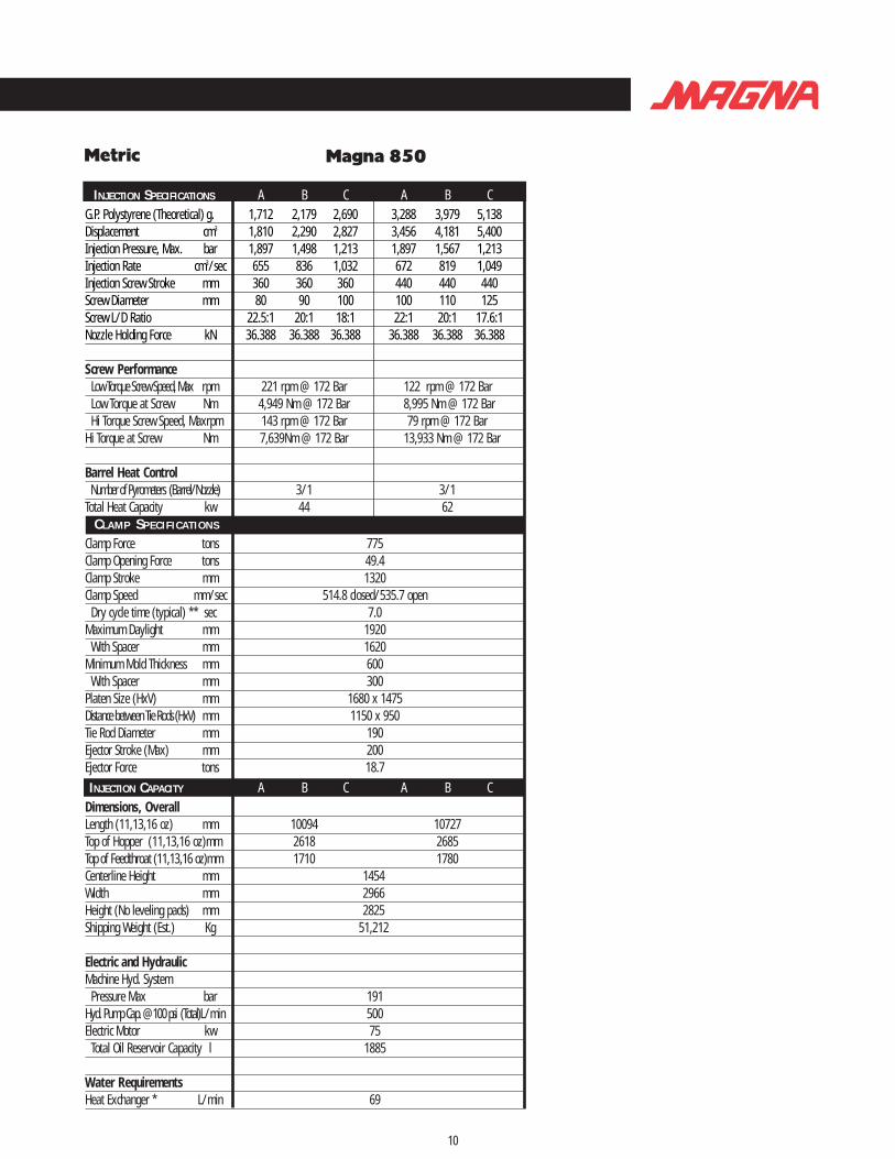
INJECTION SPECIFICATIONS A B C A B CG.P. Polystyrene (Theoretical) g. 1,712 2,179 2,690 3,288 3,979 5,138Displacement cm3 1,810 2,290 2,827 3,456 4,181 5,400Injection Pressure, Max. bar 1,897 1,498 1,213 1,897 1,567 1,213Injection Rate cm3/sec 655 836 1,032 672 819 1,049Injection Screw Stroke mm 360 360 360 440 440 440Screw Diameter mm 80 90 100 100 110 125Screw L/D Ratio 22.5:1 20:1 18:1 22:1 20:1 17.6:1Nozzle Holding Force kN 36.388 36.388 36.388 36.388 36.388 36.388
Screw PerformanceLow Torque Screw Speed, Max rpm 221 rpm @ 172 Bar 122 rpm @ 172 BarLow Torque at Screw Nm 4,949 Nm @ 172 Bar 8,995 Nm @ 172 BarHi Torque Screw Speed, Maxrpm 143 rpm @ 172 Bar 79 rpm @ 172 Bar
Hi Torque at Screw Nm 7,639Nm @ 172 Bar 13,933 Nm @ 172 Bar
Barrel Heat ControlNumber of Pyrometers (Barrel/Nozzle) 3/1 3/1
Total Heat Capacity kw 44 62CLAMP SPECIFICATIONS
Clamp Force tons 775Clamp Opening Force tons 49.4Clamp Stroke mm 1320Clamp Speed mm/sec 514.8 closed/535.7 open
Dry cycle time (typical) ** sec 7.0Maximum Daylight mm 1920
With Spacer mm 1620Minimum Mold Thickness mm 600
With Spacer mm 300Platen Size (HxV) mm 1680 x 1475Distance between Tie Rods (HxV) mm 1150 x 950Tie Rod Diameter mm 190Ejector Stroke (Max) mm 200Ejector Force tons 18.7INJECTION CAPACITY A B C A B C
Dimensions, OverallLength (11,13,16 oz) mm 10094 10727Top of Hopper (11,13,16 oz)mm 2618 2685Top of Feedthroat (11,13,16 oz)mm 1710 1780Centerline Height mm 1454Width mm 2966Height (No leveling pads) mm 2825Shipping Weight (Est.) Kg 51,212
Electric and HydraulicMachine Hyd. System
Pressure Max bar 191Hyd. Pump Cap. @100 psi (Total)L/min 500Electric Motor kw 75
Total Oil Reservoir Capacity l 1885
Water RequirementsHeat Exchanger * L/min 69
MetricMagna 600
9
INJECTION SPECIFICATIONS A B C A B C A B C A B CG.P. Polystyrene (Theoretical) g. 1,172 1,531 1,937 2,421 2,989 3,600 1,712 2,179 2,690 3,288 3,979 5,138Displacement cm3 1,242 1,232 2,036 2,545 3,142 3,801 1,810 2,290 2,8271 3,456 4,181 5,400Injection Pressure, Max. bar 1,897 1,452 1,147 1,897 1,536 1,269 1,897 1,498 1,213 1,897 1,567 1,213Injection Rate cm3/sec 475 623 787 459 557 672 475 606 7549 492 590 770Injection Screw Stroke mm 320 320 320 400 400 400 360 360 360 440 440 440Screw Diameter mm 70 80 90 90 100 110 80 90 100 100 110 1250Screw L/D Ratio 22.2:1 20:1 18.2:1 22.2:1 20:1 18.2:1 22.5:1 20:1 18:1 22.0:1 20.0:1 17.6:1Nozzle Holding Force kN 36.388 36.388 36.388 36.388 36.388 36.388 36.388 36.388 36.388 36.388 36.388 36.388
Screw PerformanceLow Torque Screw Speed, Max rpm 222 rpm @ 172 Bar 119 rpm @ 172 Bar 162 rpm @ 172 Bar 89 rpm @ 172 BarLow Torque at Screw Nm 3,593 Nm @ 172 Bar 6,746 Nm @ 172 Bar 1797 Nm @ 172 Bar 8,995 Nm @ 172 BarHi Torque Screw Speed, Max rpm 148 rpm @ 172 Bar 77 rpm @ 172 Bar 105 rpm @ 172 Bar 57 rpm @ 172 Bar
Hi Torque at Screw Nm 5,390 Nm@ 172 Bar 10,340 Nm@ 172 Bar 7,639 Nm@ 172 Bar 13,829 Nm@ 172 Bar
Barrel Heat ControlNumber of Pyrometers (Barrel/Nozzle) 3/1 3/1 3/1 3/1Total Heat Capacity kw 31 57 44.375 62CLAMP SPECIFICATIONS
Clamp Force tons 550 660Clamp Opening Force tons 31.5 31.2Clamp Stroke mm 1140 1320Clamp Speed mm/sec 491.2 closed/762.0 open 491.2 closed/762.0 open
Dry cycle time (typical) ** sec 5.5 6.0Maximum Daylight mm 1676 1780
With Spacer mm 1408 1550Minimum Mold Thickness mm 536 460
With Spacer mm 268 230Platen Size (HxV) mm 1245 x 1245 1400 x 1400Distance between Tie Rods (HxV) mm 870 x 870 950 x 950Tie Rod Diameter mm 160 170Ejector Stroke (Max) mm 200 200Ejector Force tons 12 12
MACHINE SPECIFICATIONS A B C A B C A B C A B CDimensions, OverallLength mm 9022 9750 9919 10556 Top of Hopper mm 2608 2682 2618 2685 Top of Feedthroat mm 1699 1777 1710 1780Centerline Height mm 1454 1454Width mm 2576 2693Height (No leveling pads) mm 2706 2825Shipping Weight (Est.) Kg 40,688 44,498
Electric and HydraulicMachine Hyd. System
Pressure Max bar 189 189Hyd. Pump Cap. @100 psi (Total) L/min 364 364Electric Motor kw 56 56
Total Oil Reservoir Capacity l 1302 1885
Water RequirementsHeat Exchanger * L/min 69 68
INJECTION UNIT SPECIFICATIONS
Magna 725Metric
10
Magna 850
INJECTION SPECIFICATIONS A B C A B CG.P. Polystyrene (Theoretical) g. 1,712 2,179 2,690 3,288 3,979 5,138Displacement cm3 1,810 2,290 2,827 3,456 4,181 5,400Injection Pressure, Max. bar 1,897 1,498 1,213 1,897 1,567 1,213Injection Rate cm3/sec 655 836 1,032 672 819 1,049Injection Screw Stroke mm 360 360 360 440 440 440Screw Diameter mm 80 90 100 100 110 125Screw L/D Ratio 22.5:1 20:1 18:1 22:1 20:1 17.6:1Nozzle Holding Force kN 36.388 36.388 36.388 36.388 36.388 36.388
Screw PerformanceLow Torque Screw Speed, Max rpm 221 rpm @ 172 Bar 122 rpm @ 172 BarLow Torque at Screw Nm 4,949 Nm @ 172 Bar 8,995 Nm @ 172 BarHi Torque Screw Speed, Maxrpm 143 rpm @ 172 Bar 79 rpm @ 172 Bar
Hi Torque at Screw Nm 7,639Nm @ 172 Bar 13,933 Nm @ 172 Bar
Barrel Heat ControlNumber of Pyrometers (Barrel/Nozzle) 3/1 3/1
Total Heat Capacity kw 44 62CLAMP SPECIFICATIONS
Clamp Force tons 775Clamp Opening Force tons 49.4Clamp Stroke mm 1320Clamp Speed mm/sec 514.8 closed/535.7 open
Dry cycle time (typical) ** sec 7.0Maximum Daylight mm 1920
With Spacer mm 1620Minimum Mold Thickness mm 600
With Spacer mm 300Platen Size (HxV) mm 1680 x 1475Distance between Tie Rods (HxV) mm 1150 x 950Tie Rod Diameter mm 190Ejector Stroke (Max) mm 200Ejector Force tons 18.7INJECTION CAPACITY A B C A B C
Dimensions, OverallLength (11,13,16 oz) mm 10094 10727Top of Hopper (11,13,16 oz)mm 2618 2685Top of Feedthroat (11,13,16 oz)mm 1710 1780Centerline Height mm 1454Width mm 2966Height (No leveling pads) mm 2825Shipping Weight (Est.) Kg 51,212
Electric and HydraulicMachine Hyd. System
Pressure Max bar 191Hyd. Pump Cap. @100 psi (Total)L/min 500Electric Motor kw 75
Total Oil Reservoir Capacity l 1885
Water RequirementsHeat Exchanger * L/min 69
MetricMagna 600
9
INJECTION SPECIFICATIONS A B C A B C A B C A B CG.P. Polystyrene (Theoretical) g. 1,172 1,531 1,937 2,421 2,989 3,600 1,712 2,179 2,690 3,288 3,979 5,138Displacement cm3 1,242 1,232 2,036 2,545 3,142 3,801 1,810 2,290 2,8271 3,456 4,181 5,400Injection Pressure, Max. bar 1,897 1,452 1,147 1,897 1,536 1,269 1,897 1,498 1,213 1,897 1,567 1,213Injection Rate cm3/sec 475 623 787 459 557 672 475 606 7549 492 590 770Injection Screw Stroke mm 320 320 320 400 400 400 360 360 360 440 440 440Screw Diameter mm 70 80 90 90 100 110 80 90 100 100 110 1250Screw L/D Ratio 22.2:1 20:1 18.2:1 22.2:1 20:1 18.2:1 22.5:1 20:1 18:1 22.0:1 20.0:1 17.6:1Nozzle Holding Force kN 36.388 36.388 36.388 36.388 36.388 36.388 36.388 36.388 36.388 36.388 36.388 36.388
Screw PerformanceLow Torque Screw Speed, Max rpm 222 rpm @ 172 Bar 119 rpm @ 172 Bar 162 rpm @ 172 Bar 89 rpm @ 172 BarLow Torque at Screw Nm 3,593 Nm @ 172 Bar 6,746 Nm @ 172 Bar 1797 Nm @ 172 Bar 8,995 Nm @ 172 BarHi Torque Screw Speed, Max rpm 148 rpm @ 172 Bar 77 rpm @ 172 Bar 105 rpm @ 172 Bar 57 rpm @ 172 Bar
Hi Torque at Screw Nm 5,390 Nm@ 172 Bar 10,340 Nm@ 172 Bar 7,639 Nm@ 172 Bar 13,829 Nm@ 172 Bar
Barrel Heat ControlNumber of Pyrometers (Barrel/Nozzle) 3/1 3/1 3/1 3/1Total Heat Capacity kw 31 57 44.375 62CLAMP SPECIFICATIONS
Clamp Force tons 550 660Clamp Opening Force tons 31.5 31.2Clamp Stroke mm 1140 1320Clamp Speed mm/sec 491.2 closed/762.0 open 491.2 closed/762.0 open
Dry cycle time (typical) ** sec 5.5 6.0Maximum Daylight mm 1676 1780
With Spacer mm 1408 1550Minimum Mold Thickness mm 536 460
With Spacer mm 268 230Platen Size (HxV) mm 1245 x 1245 1400 x 1400Distance between Tie Rods (HxV) mm 870 x 870 950 x 950Tie Rod Diameter mm 160 170Ejector Stroke (Max) mm 200 200Ejector Force tons 12 12
MACHINE SPECIFICATIONS A B C A B C A B C A B CDimensions, OverallLength mm 9022 9750 9919 10556 Top of Hopper mm 2608 2682 2618 2685 Top of Feedthroat mm 1699 1777 1710 1780Centerline Height mm 1454 1454Width mm 2576 2693Height (No leveling pads) mm 2706 2825Shipping Weight (Est.) Kg 40,688 44,498
Electric and HydraulicMachine Hyd. System
Pressure Max bar 189 189Hyd. Pump Cap. @100 psi (Total) L/min 364 364Electric Motor kw 56 56
Total Oil Reservoir Capacity l 1302 1885
Water RequirementsHeat Exchanger * L/min 69 68
INJECTION UNIT SPECIFICATIONS
Magna 725Metric

Standard NozzleProtrusion(.5" Max)
128.0 mm5.04 Ejector Stroke
242.0 mm9.53 K/O Bar Retracted
MovingPlaten
75.0 mm2.95
Knockout Bar
A
101.60/101.65 mm4.000/4.002
Stationary Platen
25.4 mm1.00
Optional RobotMtg Plate
420.0 mm16.54
To Robot MtgPads (2)
100.0 mm3.94
4.8 mm.19
MachineCL
160.0 mm6.30 Ram Spacer 703.5 mm
27.70 w/ StrokeRam Spacer
A
835.5 mm32.89 w/
Max DaylightRam Spacer
750.5 mm29.55 Stroke 995.5 mm
39.19 Max Daylight
132.0 mm5.20
Min Moldw/ Ram Spacer
245.0 mm9.65 Min Mold
12
R O B O T M O U N T I N G P L AT E
D I E S P A C E
8.5 mm, 30.0 mm (1.18) DPM10-6H (Pitch=1.5 mm REF )(4) Places
Optional RobotMtg Plate
(2) Machined PadsFor Robot
250.0 mm9.84
125.0 mm4.92
140.0 mm5.5
25.0 mm1.0
A-A
M O V I N G P L AT E N
11
203.2 mm8.00
177.8 mm7.00
254.0 mm10.00
304.8 mm12.00
76.2 mm TYP3.00 (4) Places
76.2 mm3.00
127.0 mm5.00
203.2 mm8.00
88.9 mm3.50
50.8 mm2.00
76.2 mm TYP3.00 (4) Places
“A”
“C”
“B”
850.0 mm33.46
VIEW A-A
NOTE: Stationary platen mounting holes same as moving platen.
HOLE DESCRIPTION:“A” - .625-11 UNC-2B 1.22" DP (68 Holes)
“B“ - 27 mm (1.063) Thru, (12 Holes)“B“ - Corresponding Hole in K/O. 14.29 mm (.562) Dr Thru
“C“ - 36.5 mm (1.44) Thru“C“ - Corresponding Hole in K/O. 1.250-7UNC-2B
76.2 mm3.00
127.0 mm5.00
177.8 mm7.00
88.9 mm3.50
304.8 mm12.00
254.0 mm10.00
50.8 mm2.00
(Distance BetweenStrain Rods. Square)
560.0 mm22.05
MAGNA 250

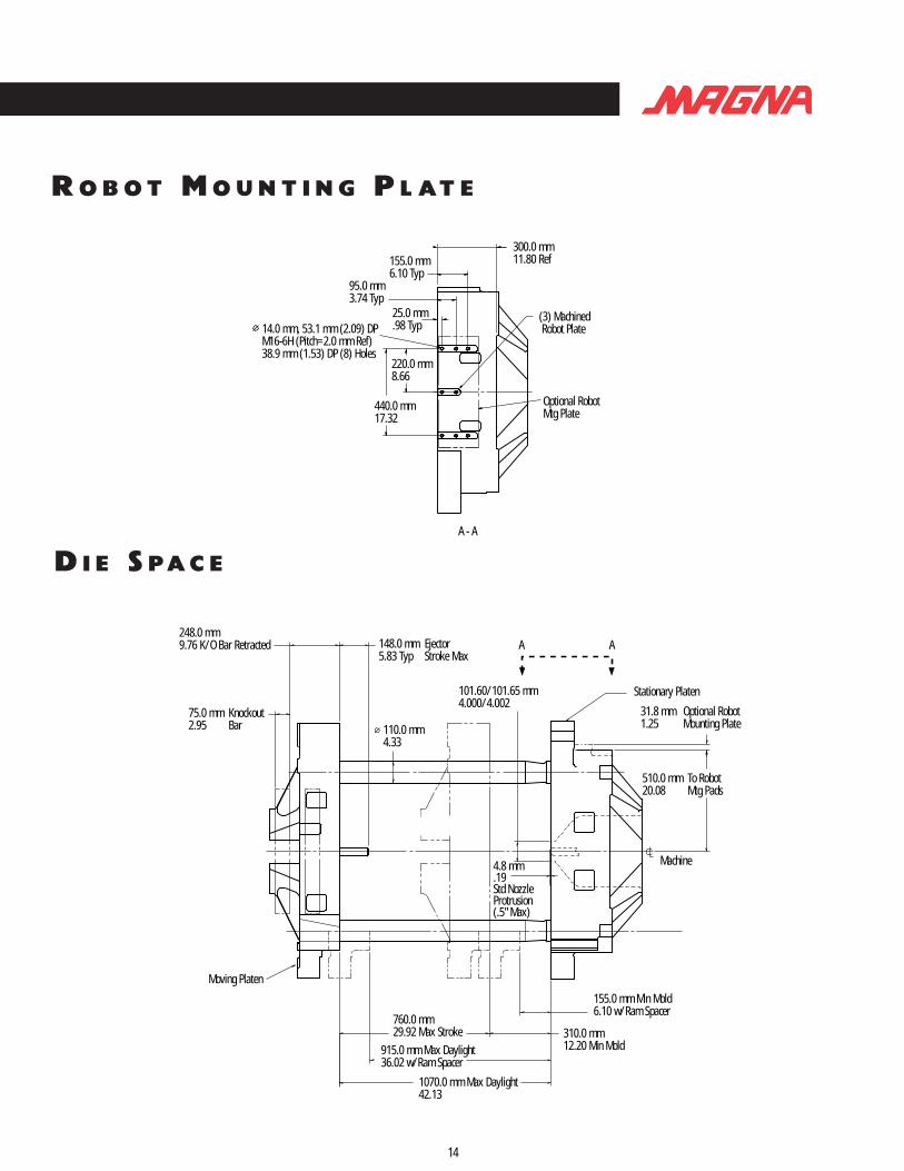
Stationary Platen
148.0 mm5.83 Typ
248.0 mm9.76 K/O Bar Retracted
75.0 mm2.95
KnockoutBar
Moving Platen
760.0 mm29.92 Max Stroke
915.0 mm Max Daylight36.02 w/Ram Spacer
1070.0 mm Max Daylight42.13
155.0 mm Min Mold6.10 w/Ram Spacer
310.0 mm12.20 Min Mold
4.8 mm.19Std NozzleProtrusion(.5" Max)
110.0 mm4.33
101.60/101.65 mm4.000/4.002
EjectorStroke Max
31.8 mm1.25
Optional RobotMounting Plate
510.0 mm20.08
To RobotMtg Pads
Machine
A A
14
R O B O T M O U N T I N G P L AT E
14.0 mm, 53.1 mm (2.09) DPM16-6H (Pitch=2.0 mm Ref)38.9 mm (1.53) DP (8) Holes
(3) Machined Robot Plate
300.0 mm11.80 Ref155.0 mm
6.10 Typ
25.0 mm.98 Typ
220.0 mm8.66
440.0 mm17.32
95.0 mm3.74 Typ
Optional RobotMtg Plate
A - A
D I E S P A C E
M O V I N G P L AT E N
13
203.2 mm8.00
Eject Mech. Stop (Ref)
Guide Rod (Ref)
127.0 mm5.0
76.2 mm3.00
177.8 mm7.00
330.2 mm13.00
381.0 mm15.00
1030.0 mm40.55
381.0 mm15.00
330.2 mm13.00
254.0 mm10.0
177.8 mm7.00
127 mm5.00
76.2 mm3.00
254.0 mm10.00
88.9 mm3.5050.8 mm2.00
Ejector Bar(Ref)
203.2 mm8.00
88.9 mm3.50
50.8 mm2.00
690.2 mm27.17
(Distance betweenstrain rods-square)
“A”
“B”“C”
NOTE: Stationary platen mounting holes same as moving platen.
HOLE DESCRIPTION:“A” - .625-11 UNC-2B 1.22" DP (92 Holes)
“B“ - 27 mm (1.063) Thru (12 Holes)“B“ - Corresponding Hole in K/O. 14.27 mm (.562) Thru
“C“ - 27.0 mm (1.063") Thru“C“ - Corresponding Hole in K/O. 1.25"-7UNC-28 Thru
MAGNA 300

31.8 mm1.25
Optional RobotMtg Plate
148.0 mm5.83
Machine
101.60/101.65 mm4.000/4.002
4.8 mm.19Standard NozzleProtrusion (.5" Max)125.0 mm
4.92
940.0 mm37.01 Max Stroke
196.0 mm Min Mold7.70 w/Ram Spacer
360.0 mm14.17 Min Mold1136.0 mm
44.72 Max Daylight w/Ram Spacer1300.0 mm51.18 Max Daylight
Moving Platen
EjectorStroke Max
253.0 mm9.96K/O Bar Retracted
85.0 mm3.35Knockout Bar
Stationary Platen
530.0 mm20.87To Robot MtgPads (3)
A A
16
R O B O T M O U N T I N G P L AT E
D I E S P A C E
14.0 mm, 42.0 mm (1.65) DPM16-6H (Pitch=2.0 mm Ref)28.0 mm (1.1) DP (14) Places
(3) Machined Robot Pads
220.0 mm8.66
440.0 mm17.32
300.0 mm11.81265.0 mm
10.43 205.0 mm8.07
155.0 mm6.10 95.0 mm
3.7425.0 mm.98
Optional RobotMtg Plate
A - A
M O V I N G P L AT E N
15
1096.0 mm43.15
203.2 mm8.00
355.6 mm14.00
88.9 mm3.50
50.8 mm2.00
Guide Rod (Ref)
Ejector Bar (Ref)
Eject Mech. Stop (Ref)
406.4 mm16.00
254.0 mm10.00
127.0 mm5.00
76.2 mm3.00
177.8 mm7.00
127.0 mm5.00
740.2 mm29.14Distance BetweenStrain Rods (Square)
355.6 mm14.00 76.2 mm
3.00
203.2 mm8.00
88.9 mm3.50
50.8 mm2.00
177.8 mm7.00254.0 mm10.00330.2 mm
13.00406.4 mm16.00
330.2 mm13.00
76.2 mm3.00
“A”
“B”
“D”
“C”
NOTE: Stationary platen mounting holes same as moving platen.
HOLE DESCRIPTION:“A” - .625-11 UNC-2B. 31.0 mm (1.22) DP. 84 Holes
“B“ - 27.0 mm (1.063) Thru. 12 Holes“B“ - Corresponding Hole in K/O. 14.29 mm (.562) Thru
“C“ - 52.4 mm (2.00) Thru, 8 Holes“C“ - Corresponding Hole in K/O. 14.29 mm (.562) Thru
“D“ - 27.0 mm (1.06) Thru, 1 Hole“D“ - Corresponding Hole in K/O. .500-13 UNC-2B, 9.9 mm (.36) DP
MAGNA 400

25.4 mm1.00
Optional RobotMtg Plate
StationaryPlaten
620.0 mm24.41
To Robot MtgPads (3)
87034.
101.60/101.65 mm4.000/4.002
148.0 mm5.83
268.0 mm10.55K/O Bar Retracted
125.0 mm4.95Knockout Bar
140.0 mm5.50
Machine4.8 mm.19Std Nozzle Protrusion(.5" Max)
191.0 mm7.52
Min Moldw/ Ram Spacer
380.0 mm14.96
1020.0 mm40.16 Max Stroke
1211.0 mm47.68
Max Daylightw/Ram Spacer
1400.0 mm55.12 Max Daylight
MinMold
Moving Platen
EjectorStroke Max
A A
18
R O B O T M O U N T I N G P L AT E
D I E S P A C E
14.0 mm, 42.0 mm (1.6) DPM16-6H (Pitch=2.0 mm Ref)28.0 mm (1.1) DP (14) Holes
380.0 mm14.96 Ref265.0 mm
10.43205.0 mm8.07
85.0 mm3.35
25.0 mm.98
145.0 mm5.71
(3) Machined Robot Pads
Optional RobotMtg Plate
600.0 mm23.622
300.0 mm11.81
A - A
M O V I N G P L AT E N
17
1254.0 mm49.37
203.3 mm8.00
88.9 mm3.50
Robot50.8 mm2.00
355.6 mm14.00
76.2 mm3.00 Guide Rod (Ref)
Eject Mech. Stop (Ref)
Ejector Bar (Ref)
127.0 mm5.00
254.0 mm10.00
330.2 mm13.00
431.8 mm17.00
533.4 mm21.00
127.0 mm5.00
50.8 mm2.00
76.2 mm3.00
355.6 mm14.0088.9 mm
3.5
870.0 mm34.3
203.2 mm8.00
Distance BetweenStrain Rods Square
177.8 mm7.00254.0 mm10.00
330.2 mm13.00431.8 mm
17.00 533.4 mm21.00
177.8 mm7.00
“A”
“B”
“D”
“C”
NOTE: Stationary platen mounting holes same as moving platen.
HOLE DESCRIPTION:“A” - .750"-10 UNC-2B 36.6 (1.44) DP, 116 Holes
“B“ - 27.0 mm (1.063) Thru, 12 Holes“B“ - Corresponding Hole in K/O. 14.29 mm (.562) Thru
“C“ - 52.4 mm (2.063) Thru, 8 Holes “C“ - Corresponding Hole in K/O. 14.29 mm (.562) Thru
“D“ - 27.0 mm (1.06) Thru, 1 Hole“D“ - Corresponding Hole in K/O. .500-13 UNC-2B. 15.4 mm (.61) DP
MAGNA 500
268.0 mm10.55
Min Moldw/Ram Spacer
633.0 mm24.92To RobotMtg Pads (3)
25.4 mm1.00
Stationary Platen200.0 mm7.87 Ejector Stroke320.0 mm
12.60K/O BarRetracted
125.0 mm4.92KnockoutBar
Moving Platen1140.0 mm44.88 Max Stroke
1408.0 mm55.43
536.0 mm21.10 Min Mold
4.8 mm.19Std NozzleProtrusion (.5" Max)
Machine
Max Daylightw/Ram Spacer
1676.0 mm65.98
MaxDaylight
160.0 mm6.3
101.60/101.65 mm4.000/4.002
Optional RobotMtg Plate
A A
20
R O B O T M O U N T I N G P L AT E
D I E S P A C E
14.0 mm, 49.0 mm (1.9) DPM16-6H (Pitch=2.0 mm Ref)35.0 mm (1.4) DP (14) Holes (3) Machined
Robot Pads
395.0 mm15.55 Ref
265.0 mm10.43 Typ205.0 mm
8.07 Typ
85.0 mm3.35 Typ
25.0 mm.98 Typ
145.0 mm5.71 Typ
Optional RobotMtg Plate
600.0 mm23.622
300.0 mm11.811
A - A
M O V I N G P L AT E N
19
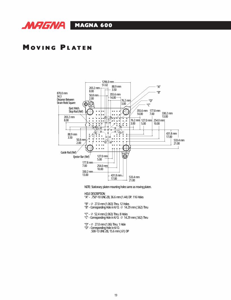
1296.0 mm51.02
203.2 mm8.0050.8 mm2.00
88.9 mm3.50
355.6 mm14.00
76.2 mm3.00
355.6 mm14.00
76.2 mm3.00
177.8 mm7.00 330.2 mm
13.00
431.8 mm17.00
533.4 mm21.00
431.8 mm17.00
330.2 mm13.00
177.8 mm7.00
Ejector Bar (Ref)Guide Rod (Ref)
870.0 mm34.3Distance BetweenStrain Rods Square
Eject Mech.Stop Rod (Ref)
203.2 mm8.00
88.9 mm3.50
50.8 mm2.00
254.0 mm10.00
127.0 mm5.00
533.4 mm21.00
127.0 mm5.00
254.0 mm10.00
“A”
“B”
“D”“C”
NOTE: Stationary platen mounting holes same as moving platen.
HOLE DESCRIPTION:“A” - .750"-10 UNC-2B, 36.6 mm (1.44) DP. 116 Holes
“B“ - 27.0 mm (1.063) Thru. 12 Holes“B“ - Corresponding Hole in K/O. 14.29 mm (.562) Thru
“C“ - 52.4 mm (2.063) Thru. 8 Holes“C“ - Corresponding Hole in K/O. 14.29 mm (.562) Thru
“D“ - 27.0 mm (1.06) Thru. 1 Hole“D“ - Corresponding Hole in K/O. .500-13 UNC-2B, 15.6 mm (.61) DP
MAGNA 600

268.0 mm10.55
Min Moldw/Ram Spacer
633.0 mm24.92To RobotMtg Pads (3)
25.4 mm1.00
Stationary Platen200.0 mm7.87 Ejector Stroke320.0 mm
12.60K/O BarRetracted
125.0 mm4.92KnockoutBar
Moving Platen1140.0 mm44.88 Max Stroke
1408.0 mm55.43
536.0 mm21.10 Min Mold
4.8 mm.19Std NozzleProtrusion (.5" Max)
Machine
Max Daylightw/Ram Spacer
1676.0 mm65.98
MaxDaylight
160.0 mm6.3
101.60/101.65 mm4.000/4.002
Optional RobotMtg Plate
A A
20
R O B O T M O U N T I N G P L AT E
D I E S P A C E
14.0 mm, 49.0 mm (1.9) DPM16-6H (Pitch=2.0 mm Ref)35.0 mm (1.4) DP (14) Holes (3) Machined
Robot Pads
395.0 mm15.55 Ref
265.0 mm10.43 Typ205.0 mm
8.07 Typ
85.0 mm3.35 Typ
25.0 mm.98 Typ
145.0 mm5.71 Typ
Optional RobotMtg Plate
600.0 mm23.622
300.0 mm11.811
A - A
M O V I N G P L AT E N
19
1296.0 mm51.02
203.2 mm8.0050.8 mm2.00
88.9 mm3.50
355.6 mm14.00
76.2 mm3.00
355.6 mm14.00
76.2 mm3.00
177.8 mm7.00 330.2 mm
13.00
431.8 mm17.00
533.4 mm21.00
431.8 mm17.00
330.2 mm13.00
177.8 mm7.00
Ejector Bar (Ref)Guide Rod (Ref)
870.0 mm34.3Distance BetweenStrain Rods Square
Eject Mech.Stop Rod (Ref)
203.2 mm8.00
88.9 mm3.50
50.8 mm2.00
254.0 mm10.00
127.0 mm5.00
533.4 mm21.00
127.0 mm5.00
254.0 mm10.00
“A”
“B”
“D”“C”
NOTE: Stationary platen mounting holes same as moving platen.
HOLE DESCRIPTION:“A” - .750"-10 UNC-2B, 36.6 mm (1.44) DP. 116 Holes
“B“ - 27.0 mm (1.063) Thru. 12 Holes“B“ - Corresponding Hole in K/O. 14.29 mm (.562) Thru
“C“ - 52.4 mm (2.063) Thru. 8 Holes“C“ - Corresponding Hole in K/O. 14.29 mm (.562) Thru
“D“ - 27.0 mm (1.06) Thru. 1 Hole“D“ - Corresponding Hole in K/O. .500-13 UNC-2B, 15.6 mm (.61) DP
MAGNA 600

710.0 mm To Robot28.00 Mtg Pads (3)
Stationary Platen101.6/101.65 mm4.000/4.002
200.0 mm Ejector7.87 Stroke Max
335.0 mm K/O Bar13.189 Retracted
125.0 mm4.921 K/O Bar
Moving Platen
170.0 mm6.7
Machine
1320.0 mm Max51.97 Stroke
460.0 mm Min18.11 Mold
230.0 mm Min Mold9.06 w/Ram Spacer
1550.0 mm Max Daylight61.02 w/Ram Spacer
1780.0 mm Max70.08 Daylight
4.8 mm - .19Std NozzleProtrusion(.5" Max)
25.4 mm Optional Robot1.00 Mtg Plate
A A
22
R O B O T M O U N T I N G P L AT E
D I E S P A C E
14.0 mm, 42.0 mm (1.7) DPM16-6H (Pitch=2.0 mm Ref)28.0 mm (1.1) DP (14) Holes
600.0 mm23.62
300.0 mm11.81
430.0 mm16.90 Ref
270.0 mm10.63210.0 mm
8.26150.0 mm5.906 90.0 mm
3.54 30.0 mm1.18
(3) Machined Robot Pads
Optional RobotMtg Plate
A - A
M O V I N G P L AT E N
21
1400.0 mm Mold55.1 Surface (Sq)
508.0 mm20.00203.2 mm
8.0088.9 mm3.5076.2 mm3.0050.8 mm2.00
355.6 mm14.00
508.0 mm20.00
203.2 mm8.00
88.9 mm3.50
76.2 mm3.00
50.8 mm2.00
Eject GuideRod (Ref)
76.0 mm3.00 Typ
76.0 mm3.00 Typ
127.0 mm5.00177.8 mm7.00254.0 mm10.00330.2 mm
13.00431.8 mm17.00533.4 mm
21.00
355.6 mm14.00
950.0 mm37.4
K/O Bar (Ref)
Eject Mech.Stop (Ref)
177.8 mm7.00
254.0 mm10.00
431.8 mm17.00
533.4 mm21.00
330.2 mm13.00
127.0 mm5.00
950.0 mm Between37.40 Strain Rods (Sq)
“A”
“B”
“C”
“D”
NOTE: Stationary platen mounting holes same as moving platen.
HOLE DESCRIPTION:“A” - .750"-10 UNC-2B, 37 (1.5) DP. 96 Holes in Moving Platen 104 Holes in Stat. Platen
“B“ - 26.99 mm (1.063) Thru. 12 Holes in Moving Platen“B“ - Corresponding Hole in K/O. 14.3 mm (.56) Thru
“C“ - 52.39 mm (2.063) Thru. 16 Holes in Moving Platen“C“ - Corresponding Hole in K/O. 14.3 mm (.56) Thru
“D“ - 26.99 mm (1.063) Thru. 1 Hole in Moving Platen“D“ - Corresponding Hole in K/O. .500-13 UNC-2B, 20.6 mm (.81) DP
MAGNA 725

Stationary Platen
200.0 mm Ejector7.87 Stroke Max
Moving Platen
350.0 mm K/O Bar13.78 Retracted
125.0 mm4.921 K/O Bar
Machine
1320.0 mm51.97 Max Stroke
600.0 mm Min23.62 Mold
300.0 mm Min Mold11.81 w/Ram Spacer
1620.0 mm Max Daylight63.78 w/Ram Spacer
1920.0 mm Max Daylight75.59
127.00/127.05 mm5.000/5.002
4.8 mm.19Std NozzleProtrusion(.5" Max)
25.4 mm Optional Robot1.00 Mtg Plate
748.0 mm To Robot29.40 Mtg Pads (3)
190.0mm7.50
A A
24
R O B O T M O U N T I N G P L AT E
480.0 mm18.90 Ref
270.0 mm10.63210.0 mm
8.26150.0 mm5.90
30.0 mm1.18
300.0 mm11.81
600.0 mm23.62
(3) Machined Robot Pads
Optional RobotMtg Plate
14.0 mm, 42.0 mm (1.70) DPM16-6H (Pitch=2.0 mm Ref)28.0 mm (1.1) DP (14) Holes
90.0 mm3.54
A - A
D I E S P A C E
23
1704.0 mm67.10
1150.0 mm45.30
660.4 mm26.00508.0 mm
20.00 355.6 mm14.00
203.2 mm8.00
50.8 mm2.00
508.0 mm20.00
440.0 mm17.32
355.6 mm14.00
203.2 mm8.00
127.0 mm5.00
76.2 mm3.00
50.8 mm2.00
Eject Guide Rod (Ref)76.0 mm3.00 Typ
76.0 mm3.00 Typ
127.0 mm5.00177.0 mm7.00
254.0 mm10.00
431.8 mm17.00
635 mm25.00736.6 mm
29.00
533.4 mm21.00
330.2 mm13.00
635.0 mm25.00
533.4 mm21.00
950.0 mm37.40
K/O Bar (Ref)Eject Mech.Stop (Ref)
177.8 mm7.00
254.0 mm10.00
127.0 mm5.00
431.8 mm17.00
330.2 mm13.00
76.2 mm3.00
127.0 mm5.00
70.0 mm2.76
88.9 mm3.50
“A”
“C”
“B”
“D”
NOTE: Stationary platen mounting holes same as moving platen.
HOLE DESCRIPTION:“A” - 1.000"-8 UNC-2B. 48 (1.9) DP, 148 Holes in Moving Platen, 160 Holes in Stationary Platen
“B“ - 26.99 mm (1.063) Thru 12 Holes“B“ - Corresponding Hole in K/O. 20.64 mm (.812) Thru
“C“ - 52.39 mm (2.063) Thru, 20 Holes “C“ - Corresponding Hole in K/O. 20.64 mm (.812) Thru
“D“ - 52.40 mm (2.063) Thru, 1 Hole“D“ - Corresponding Hole in K/O. .500-13 UNC-2B. 20.9 mm (.82) DP
MAGNA 850
M O V I N G P L AT E N

T O P V I E W
26
944.2(37.17)
Machine Length *
Max. Daylight *Clamp Stroke * Min. Mold *
30° Unit Swivel
Piping Area
Traverse ManifoldDistance Between Strain Rods *
Water In/Out ConnectionFor Feed Throat Cooling Piping Area
Extruder ManifoldInjection Manifold
PQ ManifoldHeat Exchanger
Eject And Optional Core Pull Manifold
Reservoir
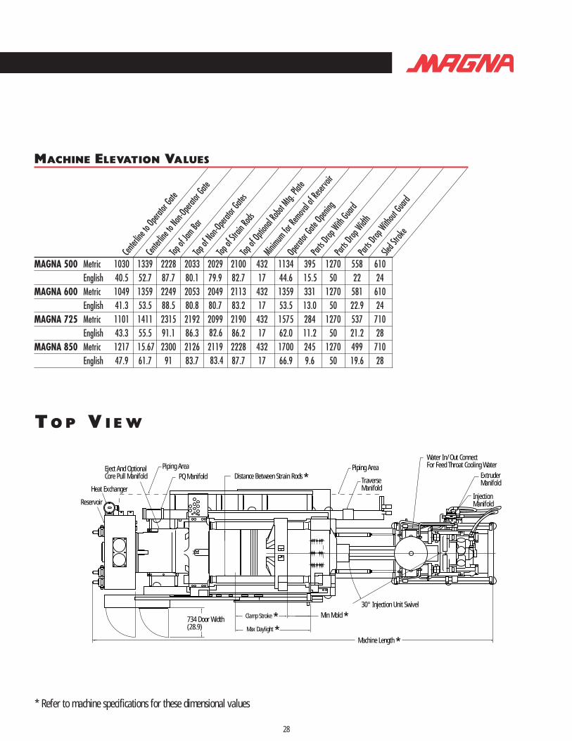
MACHINE ELEVATION VALUES
* Refer to machine specifications for these dimensional values
E N D V I E W
M AG N A 2 5 0 • 3 0 0 • 4 0 0T Y P I C A L M A C H I N E E L E VAT I O N
25
Top of Feed Throat *
OperatorPush Button Station
Gate Opening
70 Optional Leveling Pads(2.8)
Part Drop Width
Part Drop
Part DropW/O Guard
Min. Req. For Reservoir Removal
Inj. Stroke Unit
Guard
Electrical Cabinet
Sled Stroke
Topof Hopper *
65# Hopper Optional
Top OfJam Bar
Top ofNon-op Gate
Top OfStrain Rods
MachineCenterline
HeightTop Of Robot
Mtg. Plate
MachineHeight *
Machine Width *C to Non-op GateL C to Operator GateL
Electrical Connection
Heat Exchanger WaterConnect. .75" NPTF
Lubricator Fill (Zerk Fitting)Air Connect (.5 NPT)
F R O N T V I E W
* Refer to machine specifications for these dimensional values

T O P V I E W
26
944.2(37.17)
Machine Length *
Max. Daylight *Clamp Stroke * Min. Mold *
30° Unit Swivel
Piping Area
Traverse ManifoldDistance Between Strain Rods *
Water In/Out ConnectionFor Feed Throat Cooling Piping Area
Extruder ManifoldInjection Manifold
PQ ManifoldHeat Exchanger
Eject And Optional Core Pull Manifold
Reservoir
MACHINE ELEVATION VALUES
* Refer to machine specifications for these dimensional values
E N D V I E W
M AG N A 2 5 0 • 3 0 0 • 4 0 0T Y P I C A L M A C H I N E E L E VAT I O N
25
Top of Feed Throat *
OperatorPush Button Station
Gate Opening
70 Optional Leveling Pads(2.8)
Part Drop Width
Part Drop
Part DropW/O Guard
Min. Req. For Reservoir Removal
Inj. Stroke Unit
Guard
Electrical Cabinet
Sled Stroke
Topof Hopper *
65# Hopper Optional
Top OfJam Bar
Top ofNon-op Gate
Top OfStrain Rods
MachineCenterline
HeightTop Of Robot
Mtg. Plate
MachineHeight *
Machine Width *C to Non-op GateL C to Operator GateL
Electrical Connection
Heat Exchanger WaterConnect. .75" NPTF
Lubricator Fill (Zerk Fitting)Air Connect (.5 NPT)
F R O N T V I E W
* Refer to machine specifications for these dimensional values

T O P V I E W
28
Piping Area
30° Injection Unit Swivel
Machine Length *
734 Door Width(28.9)
Min Mold *Clamp Stroke *Max Daylight *
Water In/Out ConnectFor Feed Throat Cooling WaterPiping Area
PQ Manifold Distance Between Strain Rods *Eject And Optional Core Pull Manifold
Reservoir
TraverseManifold
ExtruderManifold
InjectionManifold
Heat Exchanger
MACHINE ELEVATION VALUES
* Refer to machine specifications for these dimensional values
E N D V I E W
F R O N T V I E W
M AG N A 5 0 0 • 6 0 0 • 7 2 5 • 8 5 0T Y P I C A L M A C H I N E E L E VAT I O N
27
ElectricalCabinet
Top OfInj Hopper *
OperatorPush Button Station
OptionalLeveling Pads
70(2.8)
Top ofFeed Throat *
SledStroke
InjectionUnit Stroke
Minimum Required ForRemoval Of Reservoir 315 # Hopper Optional
Gate Opening
Part DropWidth
Part Drop
Part DropW/O Guard
Machine Height * Top of
Non-opGate
Machine Width *
Top OfJam Bar
Top Of Platen
Top Of Resvr Breather
Heat ExchangerConnect .75" NPT
Air Connect
Top ofRobot Mtg Plate
MachineCenterline Height
Top OfStrain Rod
C to Non-op GateL C to Operator GateL
Electrical Connection
* Refer to machine specifications for these dimensional values
30
N O T E S
Shot Size Hopper Mounting Machine HopperOunces Capacity Pattern Bolt size Feedthroat Feedthroat
.73,1.08,1.29,1.76 65 lb. 85mm x 105mm M10 x 18mm 75mm (2.95”) 51.6mm (2.03”)
2.27,2.97,3.76 65 lb. 85mm x 105mm M10 x 18mm 75mm (2.95”) 51.6mm (2.03”)
3.51,4.44,6.04 65 lb. 85mm x 105mm M10 x 18mm 75mm (2.95”) 51.6mm (2.03”)
7.59,9.61,11.86 65 lb. 85mm x 105mm M10 x 18mm 85mm (3.35”) 51.6mm (2.03”)
2.4 65 lb. 85mm x 105mm M10 x 18mm 75mm (2.95”) 51.6mm (2.03”)
5,7,9 65 lb. 85mm x 105mm M10 x 18mm 75mm (2.95”) 51.6mm (2.03”)
8,10,12 65 lb. 85mm x 105mm M10 x 18mm 85mm (3.35”) 51.6mm (2.03”)
11,13,16 65 lb. 85mm x 105mm M10 x 18mm 95mm (3.74”) 51.6mm (2.03”)
17,20,28 115 lb. 130mm sq. M10 x 18mm 108mm (4.25”) 76mm (3.03”)
21,29,34 115 lb. 130mm sq. M10 x 18mm 108mm (4.25”) 76mm (3.03”)
31,36,47 115 lb. 130mm sq. M10 x 18mm 108mm (4.25”) 76mm (3.03”)
41,54,68 315 lb. 170mm sq. M10 x 18mm 114.3mm (4.50”) 114.3mm (4.50”)
60,76,95 315 lb. 170mm sq. M10 x 18mm 114.3mm (4.50”) 114.3mm (4.50”)
85,105,127 315 lb. 170mm sq. M10 x 18mm 114.3mm (4.50”) 114.3mm (4.50”)
116,140,181 315 lb. 170mm sq. M10 x 18mm 114.3mm (4.50”) 114.3mm (4.50”)
179,231 415 lb. 210mm sq. M12 x 30mm 140mm (5.50”) 140mm (5.50”)
288,362 415 lb. 210mm sq. M12 x 30mm 140mm (5.50”) 140mm (5.50”)
413,540 415 lb. 210mm sq. M12 x 30mm 140mm (5.50”) 140mm (5.50”)
607,769 415 lb. 210mm sq. M12 x 30mm 140mm (5.50”) 140mm (5.50”)
856,1055 415 lb. 210mm sq. M12 x 30mm 140mm (5.50”) 140mm (5.50”)
* When the mounting pattern is configured in a rectangular pattern the first dimension is parallel to the machine centerline and the second dimension isperpendicular to the centerline.
29
H O P P E R D AT A

32
N O T E SN O T E S
31

32
N O T E SN O T E S
31