8600 series vector vibrating sample magnetometer (vvsm)
TRANSCRIPT

application note
8600 Series Vector Vibrating Sample Magnetometer (VVSM)B. C. DodrillVice President, Senior Scientist
In this application note, a vibrating sample magnetometer with the vector option (VVSM) — or biaxial VSM — is described, which, in addition to standard hysteresis loop measurements, provides for measurement of the angular dependence of the vector components of the total magnetization. The VVSM also provides for indirect measurement of torque curves for anisotropy constant determinations. Two sets of sensing coils are employed to measure the components of M, from which MII — the component parallel to the applied field H, and M⫠ — the component perpendicular to H are deduced. The torque density exerted on the sample by the applied field is
τ = µo M × H = -µo M⫠Hk.
In this note, we will discuss the theory of operation and measurement methodology and present results for samples exhibiting both in-plane (IP) and out-of-plane (OOP) anisotropy.
Lake Shore Cryotronics, Inc. | t. 614.891.2243 | f. 614.818.1600 | [email protected] | www.lakeshore.comp. 2
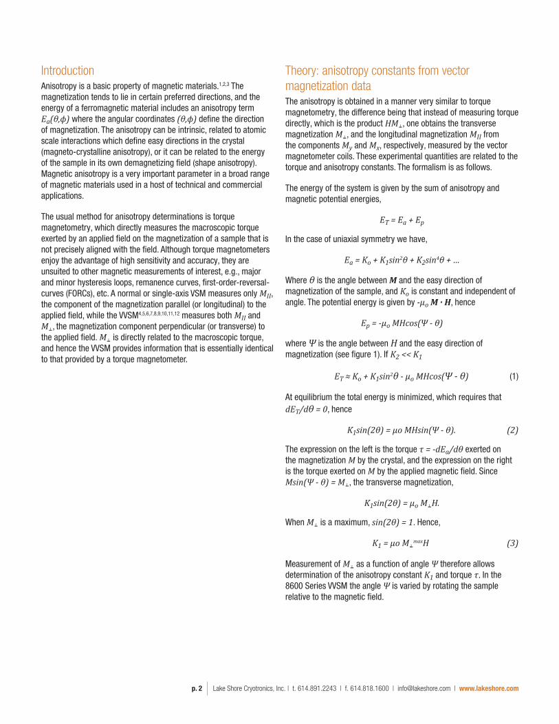
Theory: anisotropy constants from vector magnetization dataThe anisotropy is obtained in a manner very similar to torque magnetometry, the difference being that instead of measuring torque directly, which is the product HM⫠, one obtains the transverse magnetization M⫠, and the longitudinal magnetization MII from the components My and Mx, respectively, measured by the vector magnetometer coils. These experimental quantities are related to the torque and anisotropy constants. The formalism is as follows.
The energy of the system is given by the sum of anisotropy and magnetic potential energies,
ET = Ea + Ep
In the case of uniaxial symmetry we have,
Ea = Ko + K1sin2θ + K2sin4θ + …
Where θ is the angle between M and the easy direction of magnetization of the sample, and Ko is constant and independent of angle. The potential energy is given by -µo M · H, hence
Ep = -µo MHcos(Ψ - θ)
where Ψ is the angle between H and the easy direction of magnetization (see figure 1). If K2 << K1
ET ≈ Ko + K1sin2θ - µo MHcos(Ψ - θ) (1)
At equilibrium the total energy is minimized, which requires that dET/dθ = 0, hence
K1sin(2θ) = µo MHsin(Ψ - θ). (2)
The expression on the left is the torque τ = -dEa/dθ exerted on the magnetization M by the crystal, and the expression on the right is the torque exerted on M by the applied magnetic field. Since Msin(Ψ - θ) = M⫠, the transverse magnetization,
K1sin(2θ) = µo M⫠H.
When M⫠ is a maximum, sin(2θ) = 1. Hence,
K1 = µo M⫠maxH (3)
Measurement of M⫠ as a function of angle Ψ therefore allows determination of the anisotropy constant K1 and torque τ. In the 8600 Series VVSM the angle Ψ is varied by rotating the sample relative to the magnetic field.
IntroductionAnisotropy is a basic property of magnetic materials.1,2,3 The magnetization tends to lie in certain preferred directions, and the energy of a ferromagnetic material includes an anisotropy term Ea(θ,ϕ) where the angular coordinates (θ,ϕ) define the direction of magnetization. The anisotropy can be intrinsic, related to atomic scale interactions which define easy directions in the crystal (magneto-crystalline anisotropy), or it can be related to the energy of the sample in its own demagnetizing field (shape anisotropy). Magnetic anisotropy is a very important parameter in a broad range of magnetic materials used in a host of technical and commercial applications.
The usual method for anisotropy determinations is torque magnetometry, which directly measures the macroscopic torque exerted by an applied field on the magnetization of a sample that is not precisely aligned with the field. Although torque magnetometers enjoy the advantage of high sensitivity and accuracy, they are unsuited to other magnetic measurements of interest, e.g., major and minor hysteresis loops, remanence curves, first-order-reversal-curves (FORCs), etc. A normal or single-axis VSM measures only MII, the component of the magnetization parallel (or longitudinal) to the applied field, while the VVSM4,5,6,7,8,9,10,11,12 measures both MII and M⫠, the magnetization component perpendicular (or transverse) to the applied field. M⫠ is directly related to the macroscopic torque, and hence the VVSM provides information that is essentially identical to that provided by a torque magnetometer.

Lake Shore Cryotronics, Inc. | t. 614.891.2243 | f. 614.818.1600 | [email protected] | www.lakeshore.comp. 3
An alternative method of extracting a value for K1 and also a value for K2 is by fitting the torque curve to a Fourier series. All data in the torque curve is then used to calculate the anisotropy, not just the peak value.
Keeping terms in the energy to order sin4θ, the torque is:
τ(θ) ≈ (K1 + K2)sin(2θ) - 2K2sin(4θ) (4)
K1 and K2 can both be extracted by least-squares fitting the torque curve to this function. If the magnitude of the Fourier components for 2θ and 4θ are τ2θ and τ4θ respectively, then K2 = -τ4θ/2, K1 = τ2θ - K2. If we only keep terms to order sin2θ in the energy, then K1 = τ2θ.
Easy axisMY
MX
M
HX
X-axis coils
Y-axis coils
Y
X
Figure 1: Schematic top view of the vector VSM.

Lake Shore Cryotronics, Inc. | t. 614.891.2243 | f. 614.818.1600 | [email protected] | www.lakeshore.comp. 4
Examples1. Out-of-plane (OOP) anisotropy
Figures 3 and 4 show the major hysteresis loops, Mx(H) and My(H), respectively, as a function of OOP angle for a magnetic tape. The loops were measured to applied fields of ±6 kOe (0.6 T) as a function of OOP angle (Ψ) from 0° (H || tape plane) to 90° (H ⫠ tape plane) in 15° increments.
-0.02
-0.015
-0.01
-0.005
0
0.005
0.01
0.015
0.02
-6000 -4000 -2000 0 2000 4000 6000M
omen
t (em
u)Field (Oe)
Magnetic tape: Mx(H) versus OOP angle
0°
15°
30°
45°
60°
75°
90°
Figure 3: Mx(H) versus OOP angle for a magnetic tape.
-0.015
-0.01
-0.005
0
0.005
0.01
0.015
-6000 -4000 -2000 0 2000 4000 6000
Mom
ent (
emu)
Field (Oe)
Magnetic tape: My(H) versus OOP angle
0°
15°
30°
45°
60°
75°
90°
Figure 4: My(H) versus OOP angle for a magnetic tape.
Measurement methodologyA schematic top view illustration of the VVSM is shown in figure 1 with the different angles defining the directions of magnetization and applied field. One pair of sensing coils are parallel to the applied field and sense the magnetization component longitudinal to the field MII = Mx. A second set of coils is mounted at right angles to the applied field and senses the magnetization component transverse to the field M⫠ = My. Hence the VVSM may be used to measure anisotropy in the xy-plane. Sample rotation, Ψ, in the xy-plane is achieved by rotating the sample about the z axis via a computer-controlled motor attached to the VSM head. For measuring IP anisotropy, a sample is mounted to a bottom mount sample holder so that the applied field is parallel to the sample plane. For measuring OOP anisotropy, a sample is mounted to a side mount sample holder so that the orientation of the applied field can be varied from parallel (IP) to perpendicular (OOP) with respect to the sample plane. The easy and hard axis of magnetization of either IP or OOP samples may be determined by measuring Mx and My as a function of angle at remanence (H = 0). Figure 2 shows Mx and My as a function of IP angle from 0° to 360° for a magnetic tape with IP anisotropy. At remanence, My = 0 and Mx = maximum when the easy axis is aligned with the x-axis coils (i.e., parallel to the applied field direction). Alternatively, My = maximum and Mx = 0 when the easy axis is aligned with the y-coils (i.e., perpendicular to the applied field direction).
-0.01
-0.005
0
0.005
0.01
0 90 180 270 360
Mom
ent (
emu)
IP angle (y)
Magnetic tape: remanent Mx, My versus IP angle
X-moment
Y-moment
Figure 2: Mx and My as a function of IP angle from 0° to 360° for a magnetic tape at H = 0.

Lake Shore Cryotronics, Inc. | t. 614.891.2243 | f. 614.818.1600 | [email protected] | www.lakeshore.comp. 5
To derive the torque curve and anisotropy constants from the vector data, My(Ψ) was measured as a function of OOP angle from 0° ≤ Ψ ≤ 360° in 2.5° increments at an applied field of 10 kOe (1 T). The torque curve in dyne-cm derived from the Fourier analysis of the My(Ψ) results is shown in figure 5. As discussed in the Theory section, the anisotropy constants K1 and K2 are extracted by least-squares fitting the torque curve to equation (4): K1 = 12.8 × 10⁻³ dyne-cm, K2 = -1.0 × 10⁻³ dyne-cm.
-0.0025-0.002
-0.0015-0.001
-0.00050
0.00050.001
0.00150.002
0.0025
0 90 180 270 360
Torq
ue d
ensi
ty (d
yne-
cm)
Angle (θ)
Magnetic tape: torque density at 10 kOe
Figure 5: Torque curve (dyne-cm) as a function of OOP angle for a magnetic tape at H = 10 kOe (1T).
2. In-plane (IP) anisotropy
a) Uniaxially anisotropic magnetic tape
Figures 6 and 7 show the major hysteresis loops, Mx(H) and My(H), respectively, as a function of IP angle for a uniaxially anisotropic magnetic tape. The loops were measured to applied fields of ±16 kOe (1.6 T) as a function of IP angle (Ψ) from 0° (H || easy axis) to 90° (H || hard axis) in 15° increments.
-0.015
-0.01
-0.005
0
0.005
0.01
0.015
-16000 -12000 -8000 -4000 0 4000 8000 12000 16000
Mom
ent (
emu)
Field (Oe)
Magnetic tape: Mx(H) versus θ
0°
15°
30°
45°
60°
75°
90°
Figure 6: Mx(H) versus IP angle for a uniaxially anisotropic magnetic tape.
-0.008
-0.006
-0.004
-0.002
0
0.002
0.004
0.006
0.008
-16000 -12000 -8000 -4000 0 4000 8000 12000 16000
Mom
ent (
emu)
Field (Oe)
Magnetic tape: My(H) versus θ
0°
15°
30°
45°
60°
75°
90°
Figure 7: My(H) versus IP angle for a uniaxially anisotropic magnetic tape.
My(Ψ) for IP angles ranging from 0° ≤ Ψ ≤ 360° in 2.5° increments at an applied field of 25 kOe (2.5 T) was measured, and the torque curve in dyne-cm derived from the Fourier analysis of the My(Ψ) results is shown in figure 8. Least-squares fitting the torque curve to equation (4) yields anisotropy constants of: K1 = 5.1 × 10⁻² dyne-cm, K2 = -6.53 × 10⁻⁴ dyne-cm.
-0.003
-0.002
-0.001
0
0.001
0.002
0.003
0 90 180 270 360
Torq
ue d
ensi
ty (d
yne-
cm)
Angle (θ)
Magnetic tape: torque density at 25 kOe
Figure 8: Torque curve (dyne-cm) as a function of IP angle for a uniaxially anisotropic magnetic tape at H = 25 kOe (2.5 T).

Lake Shore Cryotronics, Inc. | t. 614.891.2243 | f. 614.818.1600 | [email protected] | www.lakeshore.comp. 6
My(Ψ) for IP angles ranging from 0° ≤ Ψ ≤ 360° in 1° increments at an applied field of 20 Oe (2 mT) was measured, and the torque curve in dyne-cm derived from the Fourier analysis of the My(Ψ) results is shown in figure 11. Least-squares fitting the torque curve to equation (4) yields anisotropy constants of: K1 = 3.29 × 10⁻⁴ dyne-cm, K2 = -6.17 × 10⁻⁵ dyne-cm.
-5.0E-05-4.0E-05-3.0E-05-2.0E-05-1.0E-050.0E+001.0E-052.0E-053.0E-054.0E-055.0E-05
0 90 180 270 360
Torq
ue d
ensi
ty (d
yne-
cm)
IP angle (θ)
NiFe thin �ilm: torque density at 20 Oe
Figure 11: Torque curve (dyne-cm) as a function of IP angle for NiFe thin film at H = 20 Oe (2 mT).
b) Permalloy (NiFe) multilayer thin film
The final example is for a magnetically soft (low coercivity) multilayer NiFe thin film13 with saturation moment of <60 µemu. Each successive layer in the film was deposited with an applied field at a different angle than the previous layer. Figures 9 and 10 show the major hysteresis loops, Mx(H) and My(H), respectively, for applied fields of ±40 Oe (4 mT) as a function of IP angle (Ψ) from 0° (H || easy axis) to 90° (H || hard axis) in 15° increments. These results demonstrate that the 8600 Series VVSM is well suited to measuring both low coercivity, and low moment samples.
-6.0E-05
-4.0E-05
-2.0E-05
0.0E+00
2.0E-05
4.0E-05
6.0E-05
-40 -20 0 20 40
Mx (
emu)
Field (Oe)
NiFe thin �ilm: Mx(H) versus θ
0°
15°
30°
45°
60°
75°
90°
Figure 9: Mx(H) versus IP angle for a low moment, low coercivity multilayer NiFe thin film.
-6.0E-05
-4.0E-05
-2.0E-05
0.0E+00
2.0E-05
4.0E-05
6.0E-05
-40 -20 0 20 40
My (
emu)
Field (Oe)
NiFe thin �ilm: My(H) vs θ
0°
15°
30°
45°
60°
75°
90°
Figure 10: My(H) versus IP angle for a low moment, low coercivity multilayer NiFe thin film.

Lake Shore Cryotronics, Inc. | t. 614.891.2243 | f. 614.818.1600 | [email protected] | www.lakeshore.comp. 7
SummaryIn this application note, we have presented the 8600 Series vector VSM, which in addition to major and minor hysteresis loop measurements, remanence curves, first-order-reversal-curves (FORCs), etc., also provides for measurement of the angular dependence of the vector components of the total magnetization for magnetically anisotropic materials. We have discussed the measurement methodology and the theory of operation as it relates to using the vector VSM to derive torque curves and anisotropy constants. We have presented typical measurement results for magnetic tapes exhibiting both in-plane and out-of-plane anisotropy, and a multilayer magnetic thin film with in-plane anisotropy.
References1. Experimental Magnetism, R. F. Pearson, Vol. 1 (G. M. Kalvius and R. S.
Tebble, editors) Wiley, Chichester, 1979, Ch. 3.
2. Ferromagnetism, Richard M. Bozorth, IEEE Press, NY, 1951.
3. Introduction To Magnetic Materials, B.D. Cullity, Addison-Wesley, MA, 1972.
4. Magnetometer For Anisotropy Measurement Using Perpendicular Magnetization, E. Joven, A. Del Moral, and J. I. Arnaudas, J. Mag. Mag. Mat., 83, 548, 1990.
5. Analysis of Perpendicular Recording Media Using Biaxial VSM, K. Ouchi and S. Iwasaki, IEEE Trans. Mag., 24 (6), 3009, 1988.
6. Measurement of Magnetization on an Obliquely Deposited Film by Using 3-dimensional Vector VSM, N. Matasubara, and F. Sai, IEEE Trans. Mag., 27 (6), 4748, 1991.
7. Fourfold Anisotropy of An Electrodeposited Co/Cu Compositionally Modulated Alloy, R. D. McMichael, U. Atzmony, C. Beauchamp, L. H. Bennett, L. J. Swartzendruber, D. S. Lashmore, and L. T. Romankiu, J. Mag. Mag. Mat., 113, 149, 1992.
8. An Improved Detection Coil System for a Biaxial Vibrating Sample Magnetometer, J. P. C. Bernards, G. J. P. van Engelen, and H. A. J. Cramer, J. Mag. Mag. Mat., 123, 141, 1993.
9. An Alternative Approach to Vector Vibrating Sample Magnetometer Detection Coil Setup, E. O. Samel, T. Bolhuis, and J. C. Lodder, Rev. Sci. Inst, 69, 9, 1998.
10. Method of Easy Axis Determination of Uniaxial Magnetic Films by Vector Vibrating Sample Magnetometer, S. U. Jen and J. Y. Lee, J. Mag. Mag. Mat., 271, 237, 2004.
11. Vector Vibrating Sample Magnetometer with a Permanent Magnet Flux Source, P. Stamenov and J. M. D. Coey, J. Appl. Phys., 99, 08D912, 2006.
12. Versatile and Sensitive Vibrating Sample Magnetometer, S. Foner, Rev. Sci. Inst., 30, 548, 1959.
13. Sample courtesy D. Adams, Univ. of New Orleans.

Copyright © Lake Shore Cryotronics, Inc. All rights reserved. Specifications are subject to change.
Lake Shore Cryotronics, the Lake Shore logo, the square graph logomark, and Cernox are registered trademarks of Lake Shore Cryotronics, Inc.
All other trade names referenced are the service marks, trademarks, or registered trademarks of their respective companies.
060920
Questions? Answers?
Visit http://forums.lakeshore.com/ and become part of the conversation!