860e owner's manual
TRANSCRIPT

8/8/2019 860E Owner's Manual
http://slidepdf.com/reader/full/860e-owners-manual 1/34
Print Vendor
Instructions
How to use this file
Operator’s Manuals
Paper Size: • 11x17• Body - 50 lbs brilliant white offset or equivalent
• Cover - on pre-printed two tone “Swash” stock.
Press: • Body - 1 color, 2-sided
• Cover - 1 color, 1 sided
Bindery: • Saddle stitch, face trim *if too thick for saddle stitch, tape bind
Covers: • FRONT COVER is present at the beginning of the file.
• BACK COVER is the page immediately after the front cover.
• The part number for this manual (typically a 172_____ number) islocated on the front cover.
• This file may contain several manual which differ only by their covers.See the part number at the bottom of the cover page. .
Body: • The body for all manuals is identical regardless of the cover.
• Odd number pages are always right hand pages, even number pagesare always left hand pages.
General: • This instruction sheet is NOT part of the manual and must not beprinted.
• Pages labeled “THIS PAGE INTENSIONALLY BLANK” are placementpages and should NOT be printed.

8/8/2019 860E Owner's Manual
http://slidepdf.com/reader/full/860e-owners-manual 2/34
THIS PAGE INTENTIONALLY BLANK
(FOR PLACEMENT ONLY - DO NOT PRINT)

8/8/2019 860E Owner's Manual
http://slidepdf.com/reader/full/860e-owners-manual 3/34
OPERATOR’S
MANUAL
IntermediateSnowthrower Models
555 Models
Mfg. No. Description1694587 555M, 5HP Snowthrower, Manual Start
1694595 555M, 5HP Snowthrower, Manual Start (Export)
85665 I5225, 5HP Snowthrower, Manual Start80494 EI5225, 5HP Snowthrower, Manual Start (Export)
860 ModelsMfg. No. Description
85666 I8245E, 8HP OHV Snowthrower, Electric Start80495 EI8245, 8HP OHV Snowthrower, Manual Start (Export)
1694588 860E, 8HP OHV Snowthrower, Electric Start1694596 860M, 8HP OHV Snowthrower, Manual Start (Export)
1727034
Revision 00
Rev. Date 5/2004
TP 100-4058-00-IW-SN

8/8/2019 860E Owner's Manual
http://slidepdf.com/reader/full/860e-owners-manual 4/34

8/8/2019 860E Owner's Manual
http://slidepdf.com/reader/full/860e-owners-manual 5/34
1
Table of Contents
Safety Rules & InformationTraining ...................................................................2
Preparation .............................................................2
Operation ................................................................2
Children...................................................................3
Clearing a Clogged Discharge Chute .....................3
Service, Maintenance and Storage.........................3
Emissions................................................................3
Identifications Numbers ..........................................5
Decals .....................................................................6
Safety Icons ............................................................7Features, Controls, & Operation
Control Locations ....................................................8
Starting Controls ...................................................10
Ground Speed Controls ........................................11
Auger Control........................................................11
Deflector Controls .................................................11
Scraper Height ......................................................11
Traction Lock Control............................................11General Operation
Checks Before Each Start-Up...............................12
Starting The Engine ..............................................13
Operating The Snowthrower .................................14
Clearing a Clogged Discharge Chute ...................14
Ground Speed Selector ........................................14Engine Speed .......................................................14
Deflector................................................................15
Scraper Bar & Skid Shoes ....................................15
Free Wheeling and Traction Drive Lock ................16
After Each Use......................................................16
Regular MaintenanceSchedule ...............................................................17
Checking Tire Pressure ........................................17
Checking Auger Gear Case Lubrication ...............17
Lubrication ............................................................18
Check / Lubricate Free-hand Linkage ...................19
Lubricate Auger Shaft & Assembly .......................19
Storage .................................................................19Troubleshooting, Adjustment, & Service
Troubleshooting ....................................................20
Speed Selector Pivot Adjustment .........................22
Traction Drive Clutch Cable Adjustment ...............22
Discharge Chute Worm Assy. Adjustment ............23
Discharge Chute Control Rod Gear Adjustment ...23
Auger Drive Clutch Cable Adjustment ..................24
Drive Belt Adjustment ...........................................24
Drive Belt Replacement ........................................26
Roller Chain Replacement ....................................28
Shear Pin Replacement ........................................28Specifications....................................................29Replacement Parts & Accessories ................. 30
Technical Manual availability ...........................30
WARNINGYou must read, understand and comply with all
safety and operating instructions in this manualbefore attempting to set-up and operate yoursnowthrower.
Failure to comply with all safety and operatinginstructions can result in loss of machine control,
serious personal injury to you and /orbystanders, and risk of equipment and propertydamage. The triangle in the text signifies
important cautions or warnings which must befollowed.
WARNINGEngine exhaust from this product contains
chemicals known, in certain quantities, to causecancer, birth defects, or other reproductive harm.

8/8/2019 860E Owner's Manual
http://slidepdf.com/reader/full/860e-owners-manual 6/34
2
This machine is capable of amputating hands and feet. Read these safety rules and follow them closely.
Failure to obey these rules could result in loss of control of unit, severe personal injury or death to you, orbystanders, or damage to property or equipment. The triangle in text signifies important cautions orwarnings which must be followed.
Safety Rules & Information
TP-600-3606-02-LW-UV
TRAINING
1. Read, understand, and follow all instructions on themachine and in the manuals before operating thisunit. Be thoroughly familiar with the controls and theproper use of the equipment. Know how to stop theunit and disengage the controls quickly.
2. Never allow children to operate the equipment.Never allow adults to operate the equipment withoutproper instruction.
3. Keep the area of operation clear of all persons, partic-ularly small children and pets.
4. Exercise caution to avoid slipping or falling especiallywhen operating in reverse.
PREPARATION1. Thoroughly inspect the area where the equipment is
to be used and remove all doormat, sleds, boards,wires, and other foreign objects.2. Disengage all clutches and shift into neutral before
starting engine (motor).3. Do not operate the equipment without wearing ade-
quate winter outer garments. Wear footwear that willimprove footing on slippery surfaces.
4. Handle fuel with care; it is highly flammable.(a) Use an approved fuel container.(b) Never add fuel to a running engine or hot engine.(c) Fill fuel tank outdoors with extreme care. Never fillfuel tank indoors. Replace fuel cap securely andwipe up spilled fuel.(d) Never fill containers inside a vehicle or on a truckor trailer bed with a plastic liner. Always place con-
tainers on the ground, away from your vehicle, beforefilling.(e) When practical, remove gas-powered equipmentfrom the truck or trailer and refuel it on the ground. Ifthis is not possible, then refuel such on a trailer with aportable container, rather than from a gasoline dis-penser nozzle.(f) Keep nozzle in contact with the rim of the fuel tankor container opening at all times, until refueling iscomplete. Do not use a nozzle lock-open device.(g) Replace gasoline cap securely and wipe up spilledfuel.(h) If fuel is spilled on clothing, change clothing imme-diately.
5. Use extension cords and receptacles as specified bythe manufacturer for all units with electric drive
motors or electric starting motors.6. Adjust the collector housing height to clear gravel or
crushed rock surfaces.7. Never attempt to make any adjustments while the
engine (motor) is running (except when specificallyrecommended by the manufacturer).
8. Let engine (motor) and machine adjust to outdoortemperatures before starting to clear snow.
9. Always wear safety glasses or eye shields duringoperation or while performing an adjustment or repairto protect eye from foreign objects that may bethrown from the machine.
OPERATION
1. Do not put hands or feet near or under rotating parts.Keep clear of the discharge opening at all times.2. Exercise extreme caution when operating on or
crossing gravel drives, walks, or roads. Stay alert forhidden hazards or traffic.
3. After striking a foreign object, stop the engine (motor),remove the wire from the spark plug, disconnect thecord on electric motors, thoroughly inspect thesnowthrower for any damage, and repair the damagebefore restarting and operating the snowthrower.
4. If the unit should start to vibrate abnormally, stop theengine (motor) and check immediately for the cause.Vibration is generally a warning of trouble.
5. Stop the engine (motor) whenever you leave theoperating position, before unclogging thecollector/impeller housing or discharge guide, andwhen making any repairs, adjustments, or inspec-tions.
6. When cleaning, repairing, or inspecting make certainthe collector/impeller and all moving parts havestopped. Disconnect the spark plug wire and keepthe wire away from the plug to prevent accidentalstarting.
7. Do not run the engine indoors except for starting theengine or for transporting the snowthrower in or out ofthe building. Open the outside doors; exhaust fumesare dangerous.
8. Exercise extreme caution when operating on slopes.Do not attempt to clear steep slopes.
9. Never operate the snowthrower without properguards, plates, or other safety protective devices in
place and working.10. Never direct the discharge toward people or areas
where property damage can occur. Keep childrenand others away.
11. Do not overload the machine capacity by attemptingto clear snow at too fast a rate.
12. Never operate the machine at high transport speedson slippery surfaces. Look behind and use carewhen operating in reverse.
13. Disengage power to the collector/impeller whensnowthrower is transported or not in use.
14. Use only attachments and accessories approved bythe manufacturer of the snowthrower (such as wheelweights, counterweights, or cabs).
15. Never operate the snowthrower without good visibility
or light. Always be sure of your footing, and keep afirm hold on the handles. Walk, never run.16. Never touch a hot engine or muffler.17. Never operate the snowthrower near glass enclo-
sures, automobiles, window wells, drop-offs, and thelike without proper adjustment of the discharge angle.
18. Never direct discharge at bystanders or allow anyonein front of the unit.
19. Never leave a running unit unattended. Always disen-gage the auger and traction controls, stop engine,and remove keys.
20. Do not operate the unit while under the influence ofalcohol or drugs.

8/8/2019 860E Owner's Manual
http://slidepdf.com/reader/full/860e-owners-manual 7/34
3
8. Always follow the engine manual instructions for stor-age preparations before storing the unit for both shortand long term periods.
9. Always follow the engine manual instructions forproper start-up procedures when returning the unit toservice.
10. Maintain or replace safety and instruction labels asnecessary.
11. Keep nuts and bolts tight and keep equipment ingood condition.
12. Never tamper with safety devices. Check their properoperation regularly and make necessary repairs ifthey are not functioning properly.
13. Components are subject to wear, damage, and dete-rioration. Frequently check components and replacewith manufacturer’s recommended parts, when nec-essary.
14. Check control operation frequently. Adjust and ser-vice as required.
15. Use only factory authorized replacement parts whenmaking repairs.
16. Always comply with factory specifications on all set-tings and adjustments.
17. Only authorized service locations should be utilizedfor major service and repair requirements.
18. Never attempt to make major repairs on this unitunless you have been properly trained. Improper ser-vice procedures can result in hazardous operation,equipment damage and voiding of manufacturer’swarranty.
19. Check shear bolts and other bolts at frequent inter-vals for proper tightness to be sure the equipment isin safe working condition.
EMISSIONS1. Engine exhaust from this product contains chemicals
known, in certain quantities, to cause cancer, birthdefects, or other reproductive harm.
2. If available, look for the relevant Emissions DurabilityPeriod and Air Index information on the engine emis-sions label.
Safety Rules
21. Keep in mind the operator is responsible for acci-dents occurring to other people or property.
22. Data indicates that operators, age 60 years andabove, are involved in a large percentage of powerequipment-related injuries. These operators shouldevaluate their ability to operate the unit safely enoughto protect themselves and others from injury.
23.DO NOT wear long scarves or loose clothing thatcould become entangled in moving parts.
24. Snow can hide obstacles. Make sure to remove allobstacles from the area to be cleared.
CHILDREN
Tragic accidents can occur if the operator is not alert to the
presence of children. Children are often attracted to theunit and the operating activity. Never assume that childrenwill remain where you last saw them.
1. Keep children out of the area and under the watchfulcare of another responsible adult.
2. Be alert and turn unit off if children enter the area.3. Never allow children to operate the unit.
4. Use extra care when approaching blind corners,shrubs, trees, or other objects that may obscurevision.
CLEARING A CLOGGED DISCHARGECHUTEHand contact with the rotating impeller inside the dis-charge chute is the most common cause of injury associ-ated with snowthrowers. Never use your hand to cleanout the discharge chute.To clear the chute:1. SHUT OFF THE ENGINE.2. Wait 10 seconds to be sure the impeller blades have
stopped rotating.3. Always use a clean-out tool, not your hands.
SERVICE, MAINTENANCE, AND STORAGE1. Check shear bolts and other bolts at frequent inter-
vals for proper tightness to be sure the equipment isin safe working condition.
2. Never store the machine with fuel in the fuel tankinside a building where ignition sources are presentsuch as hot water and spacer heaters, or clothes dry-ers. Allow the engine to cool before storing in anyenclosure.
3. Always refer to the operator’s manual for importantdetails if the snowthrower is to be stored for anextended period.
4. Maintain or replace safety and instruction labels as
necessary.5. Run the machine a few minutes after throwing snow
to prevent freeze-up of the collector/impeller.6. If fuel is spilled, do not attempt to start the engine but
move the machine away from the area of spillage andavoid creating any source of ignition until fuel vaporshave dissipated.
7. Always observe safe refueling and fuel handling prac-tices when refueling the unit after transportation orstorage.

8/8/2019 860E Owner's Manual
http://slidepdf.com/reader/full/860e-owners-manual 8/34
4
8/8/2019 860E Owner's Manual
http://slidepdf.com/reader/full/860e-owners-manual 9/34
5
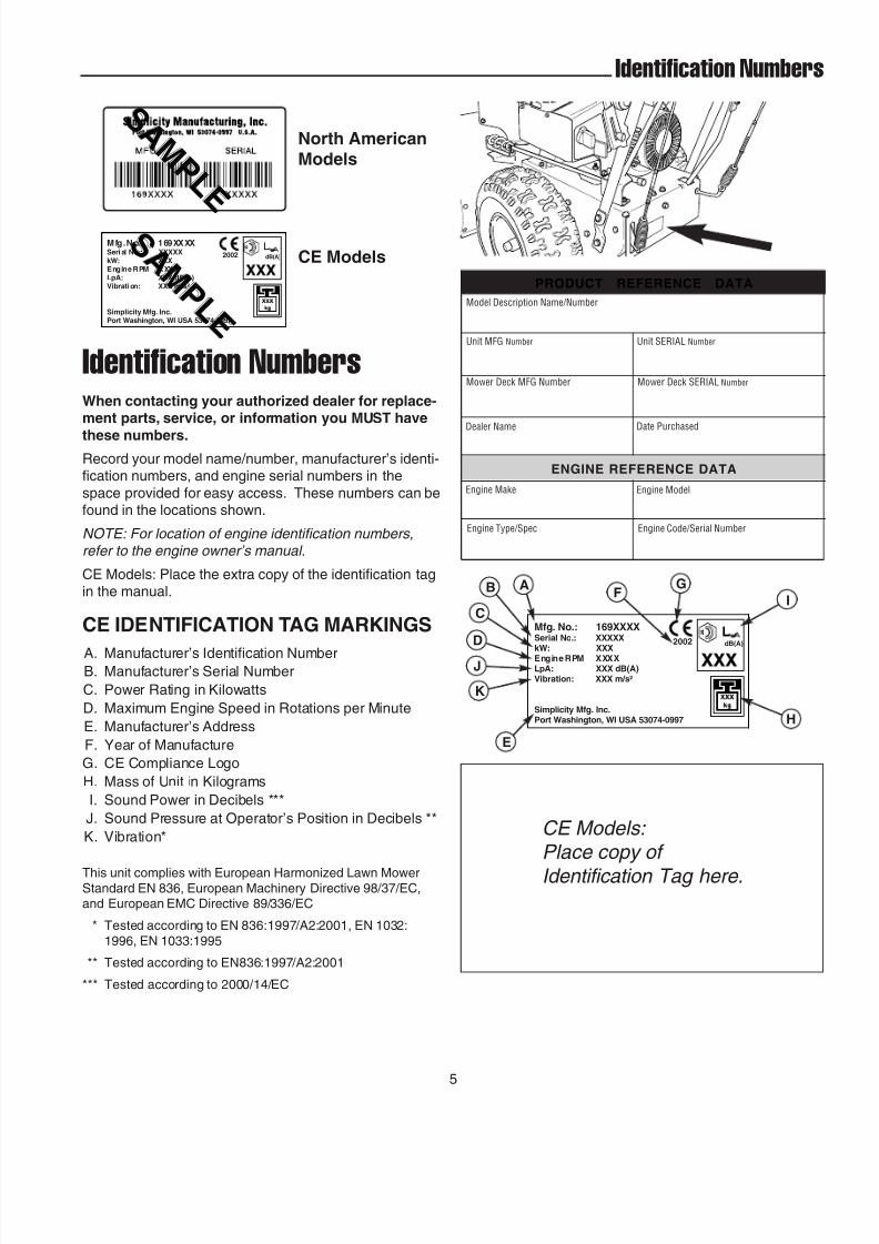
Identification Numbers
When contacting your authorized dealer for replace-ment parts, service, or information you MUST have
these numbers.Record your model name/number, manufacturer’s identi-fication numbers, and engine serial numbers in the
space provided for easy access. These numbers can befound in the locations shown.
NOTE: For location of engine identification numbers,refer to the engine owner’s manual.
CE Models: Place the extra copy of the identification tagin the manual.
Mfg. No. : 169XXXXSeri al No.: XXXXXkW: XXXEngine RPM XXXXLpA: XXX dB(A)Vibrati on: XXX m /s²
2002 dB(A)
Port Washington, WI USA 53074-0997Simplicity Mfg. Inc.
S A M P L E
S A M P L E
North AmericanModels
CE Models
ENGINE REFERENCE DATA
Model Description Name/Number
Unit MFG Number
PRODUCT REFERENCE DATA
Unit SERIAL Number
Dealer Name Date Purchased
Engine Make
Engine Type/Spec
Engine Model
Engine Code/Serial Number
Mower Deck MFG Number Mower Deck SERIAL Number
Mfg. No.: 169XXXXSerial No.: XXXXXkW: XXXEngine RPM XXXXLpA: XXX dB(A)Vibration: XXX m/s²
2002 dB(A)
Port Washington, WI USA 53074-0997Simplicity Mfg. Inc.
CE IDENTIFICATION TAG MARKINGS
A. Manufacturer’s Identification NumberB. Manufacturer’s Serial Number
C. Power Rating in Kilowatts
D. Maximum Engine Speed in Rotations per Minute
E. Manufacturer’s Address
F. Year of Manufacture
G. CE Compliance Logo
H. Mass of Unit in Kilograms
I. Sound Power in Decibels ***
J. Sound Pressure at Operator’s Position in Decibels **
K. Vibration*
This unit complies with European Harmonized Lawn MowerStandard EN 836, European Machinery Directive 98/37/EC,and European EMC Directive 89/336/EC
* Tested according to EN 836:1997/A2:2001, EN 1032:
1996, EN 1033:1995
** Tested according to EN836:1997/A2:2001
*** Tested according to 2000/14/EC
AB
C
D
J
K
E
FG
H
I
CE Models: Place copy of
Identification Tag here.
Identification Numbers

8/8/2019 860E Owner's Manual
http://slidepdf.com/reader/full/860e-owners-manual 10/34
6
Safety Decals
TractionDisengage
TractionEngage
Free HandUnlocked
Free HandLocked
AVOID SERIOUS INJURY OR DEATH
• Read the operator's manual for operating and safetyinstructions.
• Do not defeat the safety features of control. They arefor your protection.
• Keep machine properly maintained and serviced withall shields, guards, and protective devices in place.• Never allow children to operate snowthrower.• Keep area of operation clear of all persons,
especially children.
• Always direct discharge chute so as to avoidinjury to persons or damage to property.
• Stop engine and disconnect spark plug wirebefore servicing the unit.
• When traction and auger controls are depressed,the Free Hand™ control is activated. This allowsthe auger control to be released, yet augerrotation will continue until the Free Hand controlis released.
WARNING
1727020
Part No. 7071880Discharge Chute Danger Decal
Part No. 1727207Discharge Chute Danger Decal
Part No. 1727208Auger Danger Decal
Part No. 1727020WARNING / Main Dash Decal, North American Models
Part No. 1727021WARNING / Main Dash Decal, CE Models
1726946
AugerDisengage
AugerEngage
Part No. 1726946Auger Control Decal
1727023
Part No. 1727023Auger Control Decal
Part No. 1716532
Auger Danger Decal
Part No. 1722867
Lubrication Decal
Part No. 1722867Lubrication Decal
GENERAL
This unit has been designed and manufactured to pro-vide you with the safety and reliability you would expect
from an industry leader in outdoor power equipmentmanufacturing.
Although reading this manual and safety instructions itcontains will provide you with the necessary basic knowl-edge to operate this equipment safely and effectively, we
have placed several safety labels on the unit to remindyou of this important information while you are operating
your unit.
All WARNING, CAUTION, and instructional messageson your unit should be carefully read and obeyed.
Personal bodily injury can result when these instructionsare not followed. The information is for your safety and it
is important. The safety decals below are on your unit.
If any of these decals are lost or damaged, replace them
at once. See your local dealer for replacements.
These labels are easily applied and will act as a constantvisual reminder to you, and others who may use the
equipment, to follow the safety instructions necessary forsafe, effective, operation.
NORTH AMERICAN MODEL DECALS
CE MODEL DECALS
1727021

8/8/2019 860E Owner's Manual
http://slidepdf.com/reader/full/860e-owners-manual 11/34
Warning: Read Operator’s Manual.
Read and understand the Operator’sManual before using this machine.
7
CE Safety Icons & Compliance Specs
Danger: Thrown Objects.
This machine is capable of throwingobjects and debris. Keep bystanders
away.
Warning: Remove Key BeforeServicing.
Remove the key, disconnect sparkplug wire, and consult technical litera-
ture before performing repairs ormaintenance.
Warning: Dismemberment.
This machine can amputate limbs.Keep bystanders and children awaywhen engine is running.
Danger: Dismemberment.
The auger can amputate limbs. Keephands and feet away from auger androtating parts.
Danger: Dismemberment.
The impeller can amputate limbs.Stop the engine, remove the key, anddisconnect spark plug wire before
clearing the discharge chute or per-forming service work. Keep hands
and feet away from impeller and rotat-ing parts.

8/8/2019 860E Owner's Manual
http://slidepdf.com/reader/full/860e-owners-manual 12/34
8
Features, Controls, &
Operation
TECUMSEH MODELS BRIGGS & STRATTON MODELS
Please take a moment and familiarize
yourself with the name, location, and
function of these controls so that you will better understand the
safety and operating instructions provided in
this manual.
1,2..
ALL MODELS

8/8/2019 860E Owner's Manual
http://slidepdf.com/reader/full/860e-owners-manual 13/34
9
Features & Controls
Fuel
Fuel tank filler cap (see illustration). Note: The fuel shutoff valve is located under the fuel tank. Close the valve
when the snowthrower is not in use. Open the valvebefore starting.
Starter Handle
Used to pull-start the engine.
Primer Button
Primes carburetor for faster cold starting.
Throttle Lever
Controls engine speed. Move toward the hare icon forfaster engine speed, move toward the turtle icon for
slower engine speed. Move the throttle all the way toSTOP to stop the engine.
Engine Key
Prevents starting of engine without key. Stops enginewhen removed.
Choke Knob
Adjusts air/fuel mix for easier cold weather starting.
Speed Selector
Selects forward speeds 1-5 and reverse speeds 1-2.
Traction Control / Free Hand™ Lock
Engages traction drive to wheels when depressed. Alsolocks auger control when depressed simultaneously.Releasing the traction control lever releases the Free
Hand™ auger control lock and stops the drive wheels.
Auger Control
Engages the auger/impeller when depressed. Releasingthe control stops the auger/impeller.
Chute Direction Control
Rotates the discharge chute to desired position.
Chute Deflector Knob
Locks chute deflector in desired position.
Traction Lock Pins
The traction drive to each wheel can be locked andunlocked with the Traction Lock Pins (H, Figure 4) to per-
mit the unit to “free-wheel,” allowing easier manual han-dling and transport of the snowthrower.
Electric Start Button (Optional)
Activates electric starter.
CONTROL LOCATIONS
The information below briefly describes the function of individual controls. Starting, stopping, and driving require the combined use of several controls applied in specific sequences. To learn what combination and sequence of controls
to use for various tasks see the OPERATION section.
1,2..

8/8/2019 860E Owner's Manual
http://slidepdf.com/reader/full/860e-owners-manual 14/34
10
Engine Controls
STARTING CONTROLS
See Figures 1 & 2 for the following instructions.
Units with Optional Electric Start
A. Electric Start Button - The electric start button
(A) activates an electric starter mounted to theengine, eliminating the need to pull the starter han-dle. The electric start button operates on 120 Volts
AC, which is provided by connection to the extensioncord provided with units equipped with this feature.
Connect this extension cord ONLY to a properly grounded 3 prong electrical outlet.
Manual Start
B. Fuel Valve - The fuel valve (B) is located under the
fuel tank. It is used to turn the fuel supply off for out-of-season storage.
C. Starter Handle - The starter handle (C) connects to a
starter cord to manually start the engine. Pullingstarter handle rapidly spins the engine crankshaft,
cycles the engine, and generates the spark neces-sary for starting the engine.
D. Primer Button - When pressed, the primer button(D) provides initial fuel to help start a cold engine.
Normally, pressing the primer button twice will pro-vide enough fuel to start a cold engine.
E. Throttle Lever - The throttle lever (E) controls the
engine speed. For best overall performance, thethrottle lever should be set to the FAST position. Use
the SLOW position only for warming the engine, or to
help prevent snow/ice freeze-up when shutting theunit down for the day.
F. Engine Key - The engine key (F) prevents theengine from being started by unauthorized individu-
als. The key must be fully inserted into the key slotfor the unit to start. The key is also used to stop the
engine by pulling the key out of the key slot.
G. Choke Knob - The choke knob (G) adjusts theair/fuel mixture, and is used to help start a cold
engine by providing a richer mixture. Once the engineis warm and running smoothly, the choke knob
should be set to the off position to provide a normal
air/fuel mix.
Figures 2. Engine ControlsA. Electric Start Button E. Throttle LeverB. Fuel Valve F. Engine KeyC. Starter Handle G. Choke KnobD. Primer Button
B A
C
D
E
F
G
C
D
EF BG
A
TecumsehL-HeadModels
Briggs &Stratton OHVModels
Figures 1. Engine ControlsA. Electric Start Button E. Throttle LeverB. Fuel Valve F. Engine Key
C. Starter Handle G. Choke KnobD. Primer Button
8/8/2019 860E Owner's Manual
http://slidepdf.com/reader/full/860e-owners-manual 15/34
11
Controls
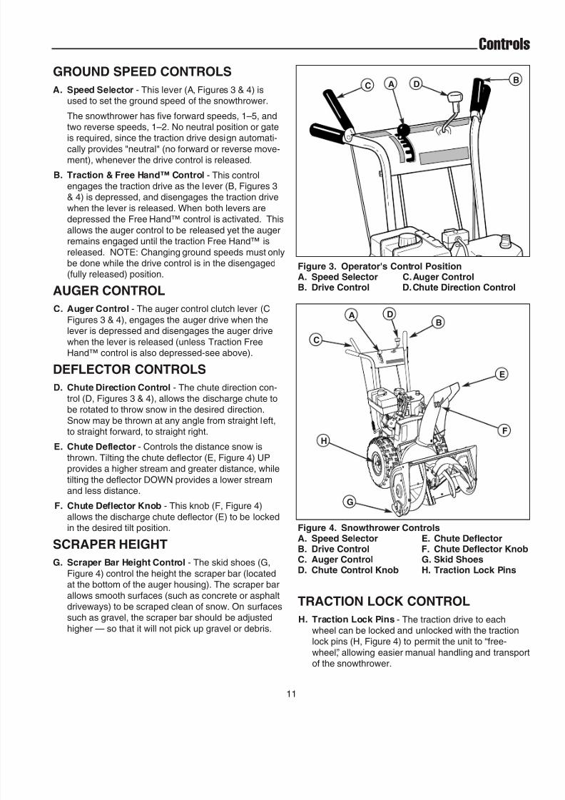
Figure 3. Operator's Control Position
A. Speed Selector C.Auger ControlB. Drive Control D.Chute Direction Control
Figure 4. Snowthrower ControlsA. Speed Selector E. Chute DeflectorB. Drive Control F. Chute Deflector Knob
C. Auger Control G. Skid ShoesD. Chute Control Knob H. Traction Lock Pins
A BC D
A DB
E
F
G
H
C
GROUND SPEED CONTROLS
A. Speed Selector - This lever (A, Figures 3 & 4) isused to set the ground speed of the snowthrower.
The snowthrower has five forward speeds, 1–5, andtwo reverse speeds, 1–2. No neutral position or gate
is required, since the traction drive design automati-cally provides "neutral" (no forward or reverse move-ment), whenever the drive control is released.
B. Traction & Free Hand™ Control - This controlengages the traction drive as the lever (B, Figures 3& 4) is depressed, and disengages the traction drive
when the lever is released. When both levers aredepressed the Free Hand™ control is activated. This
allows the auger control to be released yet the augerremains engaged until the traction Free Hand™ is
released. NOTE: Changing ground speeds must onlybe done while the drive control is in the disengaged(fully released) position.
AUGER CONTROL
C. Auger Control - The auger control clutch lever (C
Figures 3 & 4), engages the auger drive when thelever is depressed and disengages the auger drive
when the lever is released (unless Traction FreeHand™ control is also depressed-see above).
DEFLECTOR CONTROLS
D. Chute Direction Control - The chute direction con-
trol (D, Figures 3 & 4), allows the discharge chute tobe rotated to throw snow in the desired direction.
Snow may be thrown at any angle from straight left,to straight forward, to straight right.
E. Chute Deflector - Controls the distance snow is
thrown. Tilting the chute deflector (E, Figure 4) UPprovides a higher stream and greater distance, while
tilting the deflector DOWN provides a lower streamand less distance.
F. Chute Deflector Knob - This knob (F, Figure 4)
allows the discharge chute deflector (E) to be lockedin the desired tilt position.
SCRAPER HEIGHT
G. Scraper Bar Height Control - The skid shoes (G,Figure 4) control the height the scraper bar (locatedat the bottom of the auger housing). The scraper bar
allows smooth surfaces (such as concrete or asphaltdriveways) to be scraped clean of snow. On surfacessuch as gravel, the scraper bar should be adjusted
higher — so that it will not pick up gravel or debris.
TRACTION LOCK CONTROL
H. Traction Lock Pins - The traction drive to eachwheel can be locked and unlocked with the tractionlock pins (H, Figure 4) to permit the unit to “free-
wheel,” allowing easier manual handling and transportof the snowthrower.

8/8/2019 860E Owner's Manual
http://slidepdf.com/reader/full/860e-owners-manual 16/34
12
Operation
GENERAL OPERATION
CHECKS BEFORE EACH START-UP
1. Make sure all safety guards are in place and all nuts,bolts and clips are secure.
2. Check to make sure that the clean-out tool isattached to the handle on the machine. Do not oper-
ate the machine without the clean-out tool properlystored on the handle.
3. Check the engine oil level. See your engine owner’smanual for procedure and specifications.
4. Check to make sure spark plug wire is attached andspark plug is tightened securely. If necessary, torque
spark plug to 15 ft. lbs.
5. Check the fuel supply. Fill the tank no closer than 1/4
to 1/2 inch of top of tank to provide space for expan-
sion. See your engine owner’s manual for fuel recom-mendations.
6. Check the scraper bar to make sure it is set at the
desired height. Adjust the skid shoes if necessary.(See page 15.)
7. Check the drive control (B, Figure 3), and AugerControl (C) for proper operation. If adjustment is
required, see the Service Section for procedures.
8. Check the chute direction control (D, Figure 3) for
proper operation. The discharge chute should rotatefreely in both directions. See the Service Section foradjustment procedures and troubleshooting.
9. Check the chute deflector (E, Figure 3) for properoperation. The deflector should pivot freely up and
down when the chute deflector knob is loosened. Ifadjustment is required, see the Service Section for
procedures.
10. Position the chute at the desired starting direction
and set the deflector at the desired angle.
11. Check the speed selector (A, Figure 3) for smooth
operation. The control must move freely into eachspeed position gate and remain in position when
released. If the speed selector does not move freelyinto all forward and reverse speed positions, contactyour local authorized dealer for assistance.
WARNINGFor your safety, operation on slopes should be in
an up and down direction only. If it becomesnecessary to move across the face of a slope, use
caution and do not blow snow. Be very carefulwhen changing direction on a slope.
Proper winter footwear is recommended for the
operator to help prevent slipping. Never attemptto clean snow from excessively steep slopes. The
maximum slope for any operation is 17.7% (10º).
WARNINGGasoline is highly flammable and must behandled with care. Never fill the tank when the
engine is hot or running. Always move outdoorsto fill the tank. Keep snowthrower and gasolineaway from open flame or spark.
WARNINGThis unit is a “two-stage” snowthrower.
The first stage is the auger, which feeds the snowback into the impeller housing. The second stageis the impeller, which throws the snow out the
discharge chute. If bodily contact is made withthe auger or impeller when they are rotating,
severe personal injury will occur.
To avoid injury, keep others and yourself awayfrom the auger and the discharge chute whenever
the engine is running. Read and follow all of thesafety rules and warnings in this manual.
DANGERDo not clean out discharge chute with hands.
Contact with moving parts inside chute will causeserious injury. Use clean-out tool provided withmachine. Use the following procedure to remove
objects or clear the chute:
1. Stop the engine. Remove the key2. Wait 10 seconds to be sure the auger/impeller
blades have stopped rotating.3. Always use the clean-out tool. DO NOT use your
hands.

8/8/2019 860E Owner's Manual
http://slidepdf.com/reader/full/860e-owners-manual 17/34
13
Operation
STARTING THE ENGINE
1. Turn the fuel valve (B, Figure 5 & 6) to the ON posi-tion.
2. Insert the engine key (F) into the engine key slot andpush fully in to the RUN position.
3. Move the throttle lever (E) fully up to the FAST posi-tion.
4. Fully close the choke (G) if engine is cold. (Do notchoke a warm engine.)
5. Push the primerbutton (D) two times if engine is cold.(Do not prime a warm engine.)
6. Pull starter handle (C) rapidly, or push starter buttonif equipped with the electric start. Do not allow the
starter handle to snap back—let the starter roperewind slowly—while keeping a firm grip on the
starter handle.
7. As the engine starts and begins to operate evenly,open the choke (G) slowly and set the throttle lever toSLOW. If the engine falters, turn the choke knob
clockwise until the engine runs smoothly, and let itrun briefly before returning the choke to the OPENposition.
NOTE: Allow the engine to warm up at SLOW throttle for a few minutes before operating the snowthrower at full
speed. The engine will not develop full power until it reaches operating temperature.
Figures 6. Engine ControlsA. Electric Start Button E. Throttle LeverB. Fuel Valve F. Engine KeyC. Starter Handle G. Choke KnobD. Primer Button
B A
C
D
E
F
G
C
D
EF BG
A
TecumsehModels
Briggs &StrattonModels
Figures 5. Engine ControlsA. Electric Start Button E. Throttle LeverB. Fuel Valve F. Engine Key
C. Starter Handle G. Choke KnobD. Primer Button
8/8/2019 860E Owner's Manual
http://slidepdf.com/reader/full/860e-owners-manual 18/34
14
Operation
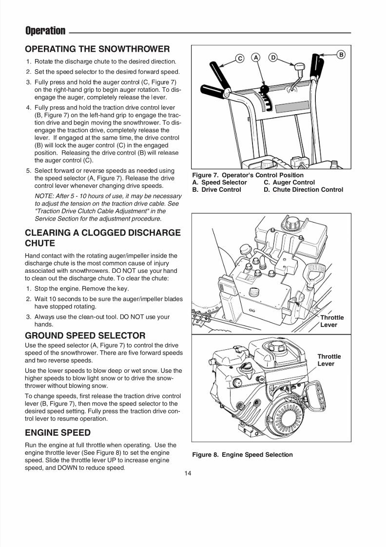
OPERATING THE SNOWTHROWER
1. Rotate the discharge chute to the desired direction.
2. Set the speed selector to the desired forward speed.
3. Fully press and hold the auger control (C, Figure 7)on the right-hand grip to begin auger rotation. To dis-
engage the auger, completely release the lever.
4. Fully press and hold the traction drive control lever
(B, Figure 7) on the left-hand grip to engage the trac-tion drive and begin moving the snowthrower. To dis-
engage the traction drive, completely release thelever. If engaged at the same time, the drive control
(B) will lock the auger control (C) in the engagedposition. Releasing the drive control (B) will releasethe auger control (C).
5. Select forward or reverse speeds as needed usingthe speed selector (A, Figure 7). Release the drive
control lever whenever changing drive speeds.
NOTE: After 5 - 10 hours of use, it may be necessary
to adjust the tension on the traction drive cable. See "Traction Drive Clutch Cable Adjustment" in the
Service Section for the adjustment procedure.
CLEARING A CLOGGED DISCHARGECHUTE
Hand contact with the rotating auger/impeller inside thedischarge chute is the most common cause of injury
associated with snowthrowers. DO NOT use your handto clean out the discharge chute. To clear the chute:
1. Stop the engine. Remove the key.
2. Wait 10 seconds to be sure the auger/impeller bladeshave stopped rotating.
3. Always use the clean-out tool. DO NOT use yourhands.
GROUND SPEED SELECTORUse the speed selector (A, Figure 7) to control the drivespeed of the snowthrower. There are five forward speeds
and two reverse speeds.
Use the lower speeds to blow deep or wet snow. Use thehigher speeds to blow light snow or to drive the snow-
thrower without blowing snow.
To change speeds, first release the traction drive control
lever (B, Figure 7), then move the speed selector to thedesired speed setting. Fully press the traction drive con-trol lever to resume operation.
ENGINE SPEED
Run the engine at full throttle when operating. Use the
engine throttle lever (See Figure 8) to set the enginespeed. Slide the throttle lever UP to increase engine
speed, and DOWN to reduce speed.
Figure 7. Operator's Control PositionA. Speed Selector C. Auger Control
B. Drive Control D. Chute Direction Control
A BC D
Figure 8. Engine Speed Selection
ThrottleLever
ThrottleLever

8/8/2019 860E Owner's Manual
http://slidepdf.com/reader/full/860e-owners-manual 19/34
15
Operation
DEFLECTOR
The distance of the discharged snow is mainly controlledby the position of the deflector (Figure 9). (Engine speed
also affects distance of discharge. Always operate atFULL throttle.)
The more the deflector is tilted UP, the farther snow willbe thrown. Loosen the deflector knob, tilt the deflectorUP or DOWN, and then retighten the knob when the
desired angle has been chosen.
Figure 10. Skid Shoe Adjustment
ScraperBar
Skid Shoe
Figure 9. Chute Deflector Adjustment
ChuteDeflector Knob
ChuteDeflector
Skid ShoeNuts
SCRAPER BAR & SKID SHOES
On smooth surfaces such as concrete or asphalt, thescraper bar should scrape the surface. On surfaces such
as gravel, the scraper bar should be high enough so thatit will not pick up gravel or debris.
The height of the scraper bar is controlled by raising orlowering the skid shoes (See Figure 10).
1. To raise the scraper bar height, rest the scraper bar
on a strip of wood equal in thickness to the desiredheight.
2. Make sure the scraper bar is parallel to the groundsurface.
3. Loosen the skid shoe nuts and let the skid shoesdrop to the surface.
4. Tighten the nuts, making sure the skid shoes areadjusted equally and are parallel to the surface.
5. To lower the height of the scraper bar, raise the skidshoes.
6. If the scraper bar becomes worn, it can be replacedby removing the hardware attaching it to the
snowthrower.

8/8/2019 860E Owner's Manual
http://slidepdf.com/reader/full/860e-owners-manual 20/34
16
Operation
Figure 11. Traction Drive Lock - Disengaged
FREE-WHEELING AND
TRACTION DRIVE LOCK
For easy turning when pushing the snowthrower, youcan disengage the traction drive at one or both wheelsby using the traction lock pins (See Figures 11 & 12).
1. Turn the unit off, remove the engine key, and discon-nect the spark plug wire.
2. To DISENGAGE the traction drive lock, insert thetraction lock pin through the outer hole in the axle.
(See Figure 11).
3. To ENGAGE the traction drive lock, insert the pin
through the hub and axle (See Figure 12). If the holein the hub is not aligned with the inner hole in the
axle, push the snowthrower until the holes align andinstall the traction lock pin.
NOTE: When snowthrowing with the full width of the
auger, for best drive performance engage both wheels.For easier turning when not using the full width of the
auger, engage one wheel and use the engaged side as the snow contact side for the auger.
Figure 12. Traction Drive Lock - Engaged
AFTER EACH USENormal use of the snowthrower may result in a build-up of packed snow in and around the starter cord housing and around engine controls. Heat from the engine willusually prevent the snow from freezing solid while theunit is running, but after the engine is shut down, somesnow may continue melting from engine heat, and laterfreeze around some moving parts as the unit cools.
After each period of use, follow these steps to prevent freeze-up caused by ice formation in and around theengine controls and external parts.
1. Before shutting off the engine, pull the starter ropeout 2 - 3 times, and allow it to rewind slowly. This willhelp clear packed snow from the starter cord area.Allow the engine to run for several minutes.
2. Stop the engine by moving the throttle lever (SeeFigure 8) down, or by pulling out the engine key.
3. Disconnect the spark plug wire, and position it awayfrom the spark plug.
4. Brush snow and ice from the snowthrower. Be sure toclear engine and snowthrower controls, dischargechute, worm and chute rod gears, clutch cable areas,and anywhere else snow has accumulated.
5. Always remove the engine key and store in a safeplace to prevent unauthorized use.
6. If the snowthrower is kept in a cold shelter, fill the fueltank to prevent condensation. Do not store nearsparks or flame.
Note: The engine owner’s manual contains further infor- mation on preventing ice formation and freeze-up.
Klik-Pin InOUTER Hole
Klik-Pin InINNER Hole
WARNINGNever store snowthrower, with gasoline in engine
or fuel tank, in a heated shelter or in enclosed,poorly ventilated enclosures. Gasoline fumes may
reach an open flame, spark or pilot light (such asa furnace, water heater, clothes dryer, etc.) and
cause an explosion.
Handle gasoline carefully. It is highly flammableand careless use can result in serious fire
damage to people and property.
Drain fuel into an approved container outdoorsaway from open flame or sparks.
8/8/2019 860E Owner's Manual
http://slidepdf.com/reader/full/860e-owners-manual 21/34
17
Regular
Maintenance
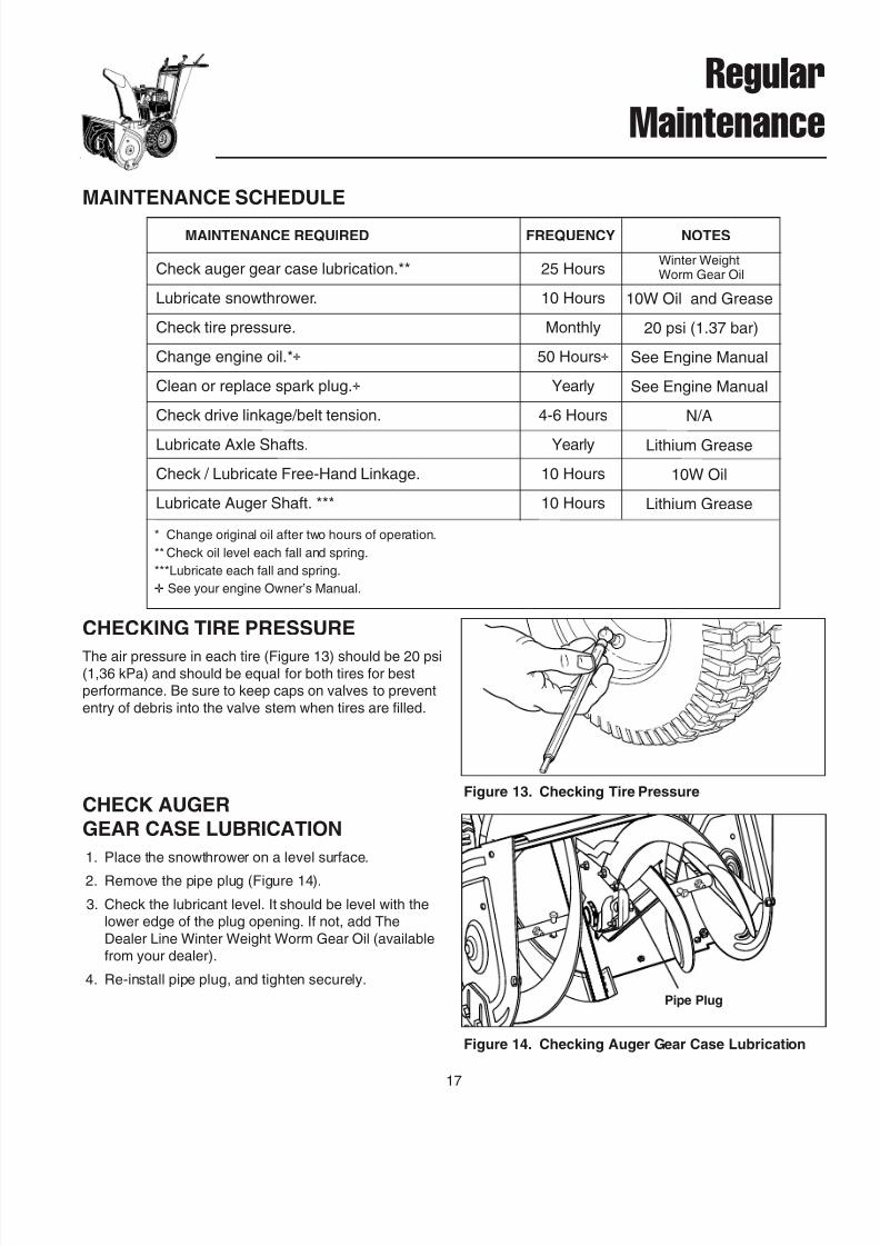
CHECK AUGER
GEAR CASE LUBRICATION
1. Place the snowthrower on a level surface.
2. Remove the pipe plug (Figure 14).
3. Check the lubricant level. It should be level with thelower edge of the plug opening. If not, add The
Dealer Line Winter Weight Worm Gear Oil (availablefrom your dealer).
4. Re-install pipe plug, and tighten securely.
Figure 14. Checking Auger Gear Case Lubrication
Pipe Plug
CHECKING TIRE PRESSURE
The air pressure in each tire (Figure 13) should be 20 psi(1,36 kPa) and should be equal for both tires for bestperformance. Be sure to keep caps on valves to prevent
entry of debris into the valve stem when tires are filled.
Figure 13. Checking Tire Pressure
MAINTENANCE SCHEDULE
Check auger gear case lubrication.**
Lubricate snowthrower.
Check tire pressure.
Change engine oil.*✛
Clean or replace spark plug.✛
Check drive linkage/belt tension.
Lubricate Axle Shafts.
Check / Lubricate Free-Hand Linkage.
Lubricate Auger Shaft. ***
25 Hours
10 Hours
Monthly
50 Hours✛
Yearly
4-6 Hours
Yearly
10 Hours
10 Hours
Winter WeightWorm Gear Oil
10W Oil and Grease
20 psi (1.37 bar)
See Engine Manual
See Engine Manual
N/A
Lithium Grease
10W Oil
Lithium Grease
MAINTENANCE REQUIRED FREQUENCY NOTES
* Change original oil after two hours of operation.
** Check oil level each fall and spring.
***Lubricate each fall and spring.
✛ See your engine Owner’s Manual.

8/8/2019 860E Owner's Manual
http://slidepdf.com/reader/full/860e-owners-manual 22/34

8/8/2019 860E Owner's Manual
http://slidepdf.com/reader/full/860e-owners-manual 23/34
19
Storage
LUBRICATION CHECK / LUBRICATE
FREE-HAND LINKAGE
Check the function of the Free-Hand controls: the con-trols should function as described in the CONTROLSsection. It is critical for the safe operation of the unit
that the controls disengage when released.
If the controls do not function properly, lubricate them. If
lubrication does not rectify the problem, see your dealer.Under no circumstances should the unit be used if thecontrols are not functioning properly.
Figure 17. Lubricate Free Hand Control
STORAGE
Before you store your unit for the off-season, read theMaintenance and Storage instructions in the SafetyRules section, then perform the following steps:
• Disengage the PTO, set the parking brake, andremove the key.
• Perform engine maintenance and storage measureslisted in the engine owner’s manual. This includesdraining the fuel system, or adding stabilizer to the
fuel (do not store a fueled unit in an enclosed struc-ture - see warning).
WARNINGNever store the unit (with fuel) in an enclosed,poorly ventilated structure. Fuel vapors can
travel to an ignition source (such as a furnace,water heater, etc.) and cause an explosion.
Fuel vapor is also toxic to humans and animals.
Figure 18. Checking Auger Gear Case LubricationA. Grease Fittings C. Cotter PinsB. Shear Pins D. Auger Assembly
A
B
D
C
LUBRICATING THE AUGER SHAFT &
ASSEMBLY
1. Remove cotter pin (C, Figure 18) and shear pin (B).
2. Use a grease gun and squirt several shots of grease
into grease fitting (A).
3. Rotate auger assembly (D) several times to distribute
the grease evenly. Repeat step 2.
4. Reinstall shear pin (B) and cotter pin (C).
5. Repeat procedure for other side.
A
B
D
C
IMPORTANT NOTE
It is very important that grease fittings on the auger shaftare lubricated regularly. If auger rusts to shaft, damage to
worm gear may occur if shear pins do not break.
Before starting the unit after it has been stored:
• Check all fluid levels. Check all maintenance items.
• Perform all recommended checks and proceduresfound in the engine owner’s manual.
• Allow the engine to warm up for several minutesbefore use.

8/8/2019 860E Owner's Manual
http://slidepdf.com/reader/full/860e-owners-manual 24/34
Troubleshooting,Adjustment, & Service
20
PROBLEM POSSIBLE CAUSE REMEDYEngine fails to start. 1. Key is OFF.
2. Failure to prime cold engine
3. Fuel valve is in CLOSED position.
4. Out of fuel.
5. Choke OFF - cold engine.
6. Engine flooded.
7. Spark plug not sparking.
8. Water in fuel, or old fuel.
1. Push key in to the ON position.
2. Press Primer Button twice and restart.
3. Turn valve to OPEN position.
4. Fill fuel tank.
5. Turn choke to ON, set throttle to
FAST.
6. Turn choke to OFF; try starting.
7. Check gap. Gap plug, clean elec-
trode, or replace plug as necessary.
8. Drain tank (Dispose of fuel at an
authorized hazardous waste facility).Fill with fresh fuel.
Engine starts hard or runs poorly. 1. Fuel mixture too rich.
2. Carburetor adjusted incorrectly.
3. Spark plug faulty, fouled, or gappedimproperly.
4. Fuel cap vent is blocked.
1. Move choke to OFF position.
2. See your dealer for adjustments.
3. Clean and gap, or replace.
4. Clear vent.
Auger does not rotate. 1. Auger control not engaged.
2. Foreign matter blocking auger.
3. Auger drive clutch cable slack.
4. Auger drive belt slipping.
5. Broken belt.
6. Shear pin broken.
1. Engage auger control.
2. STOP engine and REMOVE the key.
DISCONNECT the spark plug wire.
Clear auger using clean-out tool. See
warning in SAFETY RULES.
3. Tighten to remove slack. See auger
clutch cable adjustment.
4. Check auger drive belt adjustment.
5. Replace belt.
6. Replace shear pin.
TROUBLESHOOTING
This section provides troubleshooting and service
instructions. Locate the problem and check the possiblecause/remedy in the order listed.
Also, refer to the engine manufacturer’s Owner’s Manual
for additional information.
For problems not covered here, contact your local deal-
er.
WARNINGBefore performing any adjustment or service tosnowthrower, stop the engine and wait for
moving parts to stop. Remove the key. To preventaccidental starting, disconnect the spark plugwire and fasten away from the plug.

8/8/2019 860E Owner's Manual
http://slidepdf.com/reader/full/860e-owners-manual 25/34
21
Troubleshooting
PROBLEM POSSIBLE CAUSE REMEDY
Auger rotates, but snow is not
thrown far enough
1. Chute deflector too low.
2. Engine speed too slow.
3. Ground speed too fast.
4. Snowthrower discharge chute clogged.
5. Auger belt loose or worn.
1. Adjust deflector as necessary.
2. Set speed to full throttle.
3. Use slower speed selector setting.
4. STOP engine and REMOVE the key.
DISCONNECT the spark plug wire.Clear auger using clean-out tool. See
warning in SAFETY RULES.
5. Check auger drive belt adjustment
Scraper bar does not clean hardsurface.
1. Skid shoes improperly adjusted. 1. RAISE skid shoes (this lowers the
scraper bar).
Auger does not stop when augerlever is released
1. Auger clutch cable too tight or bent.2. Auger drive belt out of adjustment.
3. Auger belt guide out of adjustment.
4. Free hand control not releasing.
1. Loosen or straighten clutch cable.2. Adjust auger belt.
3. Adjust auger belt guide.
4. Lubricate free hand linkage.
Scraper bar picks up and throwsstones on gravel drive.
1. Skid shoes improperly adjusted. 1. LOWER skid shoes (this raises the
scraper bar.)
Poor traction 1. Tires slipping. 1. Check tire pressure and tread.
Snowthrower does not stop whendrive lever is released
1. Traction drive clutch cable bent or too
tight.
1. Loosen cable to remove slack or
replace. See adjustment procedure.
Snowthrower does not drive whendrive lever is engaged.
1. Traction drive clutch cable loose.
2. Drive belt loose, broken, or stretched.
3. Drive roller chain damaged.
4. Traction lock pins in free-wheeling
position (OUTER hole).
5. Friction disc worn.
1. Tighten to remove slack. See adjust-
ment procedure.
2. Replace drive belt.
3. Replace chain.
4. Change traction lock pins to INNER
hole to engage traction drive.
5. Replace disc (see your dealer).
Discharge control is difficult to
operate.
1. Gearing needs lubrication
2. Worm gear not adjusted properly.
3. Control rod gears misaligned.
4. Pin connecting control shaft broken.
1. Oil or grease as required.
2. Adjust worm gear. See adjustment
procedure.
3. Adjust gear bracket. See adjustment
procedure.
4. Replace pin.
Snowthrower veers to one side. 1. Tire pressure not equal.
2. One wheel is set in free-wheeling
mode. (Traction lock pin is in the
OUTER hole).
1. Check tire pressure.
2. Make certain BOTH traction lock pins
are in the INNER holes (to engage
traction drive).
Excessive vibration. 1. Loose parts or damaged auger. 1. STOP engine and REMOVE the key.
DISCONNECT the spark plug wire.
Tighten all hardware. Replace auger
if necessary. If vibration continues,
see your dealer.
Drive fails to move snowthrowerat slow speeds.
1. Traction drive out of adjustment. 1. Readjust drive, or shift speed selector
setting up one speed faster.

8/8/2019 860E Owner's Manual
http://slidepdf.com/reader/full/860e-owners-manual 26/34
22
Adjustments
SPEED SELECTOR PIVOT ADJUSTMENT
The speed selector is factory set for optimal performanceat each forward and reverse speed setting. However, if
drive system components have been replaced, adjust-ment may be necessary.
Adjust as follows:1. Move the ground speed control (A, Figure 19) fully
forward.
2. Loosen the hardware (B) securing the upper andlower shift rods.
3. Push the lower rod (C) down fully (into the housing).
4. Make sure the ground speed control (A) is in the full
forward (5th gear) position. Pull the two rods apartand tighten the shift rod hardware (B).
Figure 19. Speed Selector Linkage AdjustmentA. Ground Speed LeverB. Shift Rod HardwareC. Lower Shift Rod
TRACTION DRIVE CLUTCH CABLE
ADJUSTMENT
Initial Adjustment
The traction drive clutch cable should initially be adjusted
so that there is no slack in the cable when moved slightlyfrom side to side, but bellcrank arm remains in fully down
position. To adjust tension on the cable:
1. Loosen adjustment hex nut (Figure 20) by holding theadjusting flats and turning adjustment hex nut.
2. Tighten adjustment screw by turning adjustment flats
and holding screw. The adjustment screw is aphillips screw and the head can be held or turned byinserting a screwdriver through the traction drive
clutch cable spring. Tighten just until slack in cableis removed.
3. Tighten hex nut securely. The unit should able to bepushed forward and back freely.
Figure 20. Traction Drive Clutch Cable Adjustment
Traction DriveClutch Cable
Traction DriveClutch Cable Spring
AdjustmentScrew
Traction DriveBellcrank Arm
Run-In Adjustment
1. After 5 hours of use, check for proper adjustment.
Readjust clutch cable if necessary by increasing ten-sion on cable. A small amount of bellcrank arm
movement is permissible if unit passes operatingchecks described in the Caution at left. Optimaladjustment provides 3/16" clearance between
traction drive disc and rubber ring on friction discwhen drive lever is released (see Figure 15 for fric-
tion disk location).
WARNING
Do not over-tighten, as this may cause tractiondrive to engage without depressing the traction
drive control (bellcrank arm must remain in downposition).
Verify that the cables are not over-tightened: With
speed selector in position 1 and traction drivecontrol fully released, push snowthrower forward.
The unit should move forward freely.
If unit does not move forward freely, the cable hasbeen over-tightened. To remedy, loosen tension
on clutch cable slightly, and recheck.
A
B
C
AdjustmentFlats
AdjustmentHex Nut

8/8/2019 860E Owner's Manual
http://slidepdf.com/reader/full/860e-owners-manual 27/34
23
Adjustments
MANUAL DISCHARGE CHUTE
CONTROL LINKAGE ADJUSTMENT
Pinion Gear Adjustment
If the discharge chute is difficult to operate, first lubricatethe pinion gear (A, Figure 21) and ring gear (F). If it isstill difficult to operate, adjust as follows:
NOTE: If the discharge chute will not stay in position,adjust the pinion gear (A) closer to the ring gear (F).
1. Loosen the nut (G, Figure 23) which holds the pinion
gear bracket in the slotted hole.
2. If the pinion gear is too tight against the ring gear,
move it away slightly and then retighten the nut.
3. Check the operation again.
Figure 22. Chute Direction Gear Adjustments
CHUTE DIRECTION CONTROL
ROD GEAR ADJUSTMENTIf the discharge chute becomes difficult to rotate orbegins to operate erratically, the chute direction controlrod gears may require adjustment:
1. Loosen the gear bracket mounting nuts (Figure 22).2. Slide the gear bracket into the position that provides
the best engagement between the gears.
3. Tighten the bracket mounting nuts, and check forsmooth operation.
4. Readjust if necessary.
5. Lubricate the chute direction control rod gears with amedium weight (10W) oil.
Mounting Nuts
Figure 21. Discharge ControlA. Pinion GearB. Control RodC. Carriage Bolt
D. Slotted BracketE. U-shaped BracketF. Ring GearG. Nut
B
C
G
A
E
F
D

8/8/2019 860E Owner's Manual
http://slidepdf.com/reader/full/860e-owners-manual 28/34

8/8/2019 860E Owner's Manual
http://slidepdf.com/reader/full/860e-owners-manual 29/34
25
Adjustments
DRIVE BELT ADJUSTMENT (Continued)
If the auger drive slips (auger slows or doesn't rotate nor-mally while blowing snow), or stays engaged when thecontrol is disengaged — and the auger clutch cable has
been properly adjusted — the auger drive belt may beout of adjustment.
Checking Auger Belt & Belt GuideAdjustments
1. Insert the engine key and start the snowthrower.
2. Engage and disengage the auger control a series often times, checking that the auger comes to a com-
plete stop within 5 seconds after the control is disen-gaged each time.
3. If the auger comes to a complete stop each time with-in 5 seconds, the adjustment is correct. If the auger
does NOT come to a complete stop within the neces-sary 5 seconds, the adjustment is incorrect: readjust-
ing the auger belt & belt guide according to the pro-cedures below.
Adjusting Auger Drive Belt
1. Make certain that the snowthrower is off, the engine
key has been removed, and the spark plug discon-nected.
2. Check that there is no slack in the auger drive clutch
cable (see Figure 26). If there is, follow the augerdrive clutch cable Adjustment procedure on page 24.
3. Measure the length of the auger drive clutch spring(Figure 26).
4. Fully depress the auger control and measure theexpanded length of the spring.
The spring should expand 19/64”-5/16”. If the springdeflection is less than 19/64”-5/16” the auger idler
pulley must be adjusted. Proceed to step 5.5. Loosen the belt cover screws and remove the belt
cover (Figure 25)
6. Loosen the adjustment bolt (see Figure 27) and movethe auger idler pulley.
7. Tighten the adjustment bolt and repeat steps 3-4.
8. Test run the unit. The auger must NOT rotate unlessthe auger control lever has been depressed. Properauger drive belt adjustments stop the auger within 5seconds after the auger control is disengaged. If theauger drive fails either of these tests, repeat theadjustment procedures.
Figure 25. Auger Control and Belt Cover Location
Belt Cover
Auger Control
Figure 27. Auger Drive Belt, Guide and Pulley
Auger Idler
Pulley
Auger IdlerArm
Adjustment
BoltAuger
Drive Belt
Figure 26. Auger Drive Clutch Cable
Auger DriveClutch Cable
AdjustmentHex Nut
Idler Rod Right Handle
Measure SpringLength, SpringShould Expand5/16” When Augeris Engaged
9. After adjusting the auger drive belt, the auger beltguide MUST BE adjusted according to the Adjusting
Auger Belt Guide procedure which follows.
WARNINGAuger must NOT rotate unless the Auger Control
lever has been depressed. Proper Auger Drive Belt adjustments stop the auger within 5 seconds
after the Auger Control is disengaged.
8/8/2019 860E Owner's Manual
http://slidepdf.com/reader/full/860e-owners-manual 30/34
26
Adjustments & Service
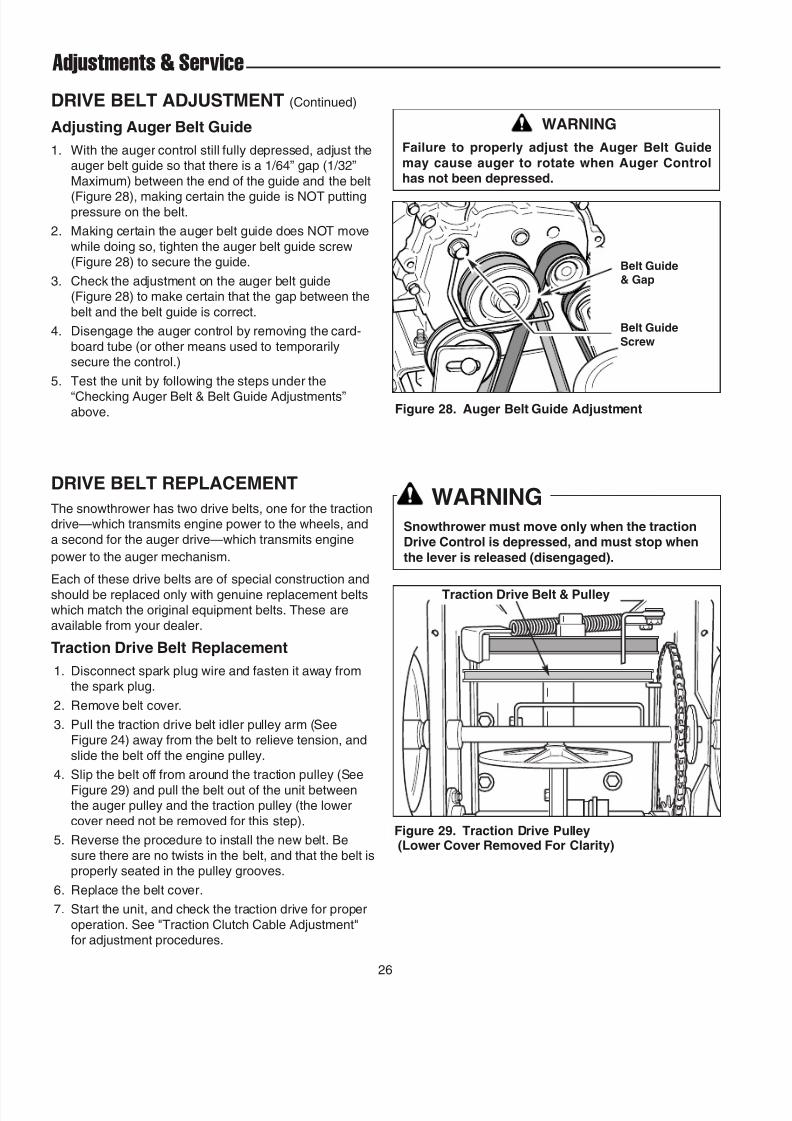
DRIVE BELT ADJUSTMENT (Continued)
Adjusting Auger Belt Guide
1. With the auger control still fully depressed, adjust theauger belt guide so that there is a 1/64” gap (1/32”
Maximum) between the end of the guide and the belt
(Figure 28), making certain the guide is NOT puttingpressure on the belt.
2. Making certain the auger belt guide does NOT move
while doing so, tighten the auger belt guide screw(Figure 28) to secure the guide.
3. Check the adjustment on the auger belt guide(Figure 28) to make certain that the gap between the
belt and the belt guide is correct.
4. Disengage the auger control by removing the card-
board tube (or other means used to temporarilysecure the control.)
5. Test the unit by following the steps under the
“Checking Auger Belt & Belt Guide Adjustments”above. Figure 28. Auger Belt Guide Adjustment
WARNING
Failure to properly adjust the Auger Belt Guide
may cause auger to rotate when Auger Controlhas not been depressed.
Belt Guide& Gap
Belt Guide
Screw
Figure 29. Traction Drive Pulley(Lower Cover Removed For Clarity)
Traction Drive Belt & Pulley
DRIVE BELT REPLACEMENT
The snowthrower has two drive belts, one for the tractiondrive—which transmits engine power to the wheels, and
a second for the auger drive—which transmits engine
power to the auger mechanism.
Each of these drive belts are of special construction and
should be replaced only with genuine replacement beltswhich match the original equipment belts. These are
available from your dealer.
Traction Drive Belt Replacement
1. Disconnect spark plug wire and fasten it away fromthe spark plug.
2. Remove belt cover.
3. Pull the traction drive belt idler pulley arm (SeeFigure 24) away from the belt to relieve tension, and
slide the belt off the engine pulley.
4. Slip the belt off from around the traction pulley (See
Figure 29) and pull the belt out of the unit betweenthe auger pulley and the traction pulley (the lower
cover need not be removed for this step).
5. Reverse the procedure to install the new belt. Be
sure there are no twists in the belt, and that the belt isproperly seated in the pulley grooves.
6. Replace the belt cover.
7. Start the unit, and check the traction drive for proper
operation. See "Traction Clutch Cable Adjustment"for adjustment procedures.
WARNINGSnowthrower must move only when the tractionDrive Control is depressed, and must stop when
the lever is released (disengaged).
8/8/2019 860E Owner's Manual
http://slidepdf.com/reader/full/860e-owners-manual 31/34
27
Service
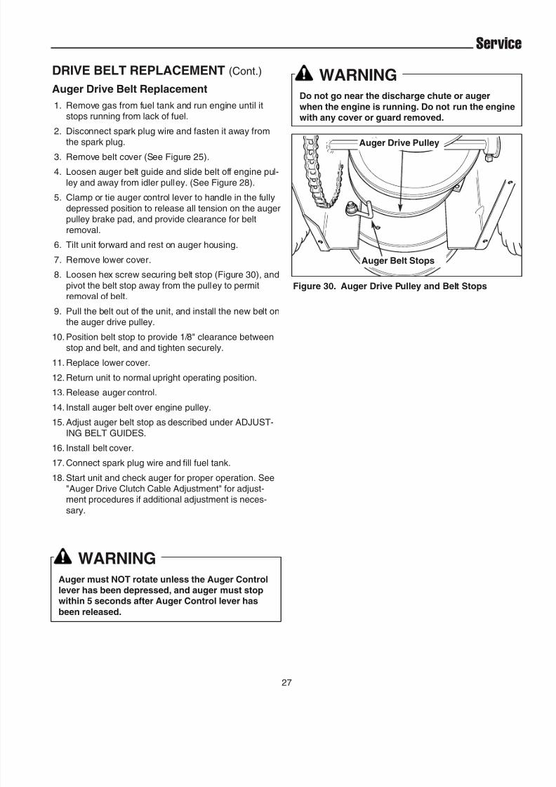
DRIVE BELT REPLACEMENT (Cont.)
Auger Drive Belt Replacement
1. Remove gas from fuel tank and run engine until itstops running from lack of fuel.
2. Disconnect spark plug wire and fasten it away fromthe spark plug.
3. Remove belt cover (See Figure 25).
4. Loosen auger belt guide and slide belt off engine pul-
ley and away from idler pulley. (See Figure 28).
5. Clamp or tie auger control lever to handle in the fully
depressed position to release all tension on the augerpulley brake pad, and provide clearance for belt
removal.
6. Tilt unit forward and rest on auger housing.
7. Remove lower cover.
8. Loosen hex screw securing belt stop (Figure 30), andpivot the belt stop away from the pulley to permitremoval of belt.
9. Pull the belt out of the unit, and install the new belt onthe auger drive pulley.
10. Position belt stop to provide 1/8" clearance betweenstop and belt, and and tighten securely.
11. Replace lower cover.
12. Return unit to normal upright operating position.
13. Release auger control.
14. Install auger belt over engine pulley.
15. Adjust auger belt stop as described under ADJUST-
ING BELT GUIDES.
16. Install belt cover.
17. Connect spark plug wire and fill fuel tank.
18. Start unit and check auger for proper operation. See"Auger Drive Clutch Cable Adjustment" for adjust-ment procedures if additional adjustment is neces-
sary.
Figure 30. Auger Drive Pulley and Belt Stops
Auger Belt Stops
Auger Drive Pulley
WARNINGDo not go near the discharge chute or auger
when the engine is running. Do not run the enginewith any cover or guard removed.
WARNINGAuger must NOT rotate unless the Auger Controllever has been depressed, and auger must stopwithin 5 seconds after Auger Control lever has
been released.

8/8/2019 860E Owner's Manual
http://slidepdf.com/reader/full/860e-owners-manual 32/34
28
Service
SHEAR PIN REPLACEMENT
Under most circumstances, if the auger strikes an object
which could cause damage to the unit, the shear pin willbreak. (This protects the gear box and other parts from
damage.)
The shear pins are located on the auger shaft as shown
in Figure 32. To replace the shear pins, tap out brokenpin with a pin punch, and install a new shear pin and cot-ter pin. Spread the legs of the new cotter pin fully. Do
NOT replace shear pins with anything other than thecorrect grade replacement shear pin. See the
REPLACEMENT PARTS section at the back of this man-ual for the correct part numbers. (Use of bolts, screws or
a harder shear pin will lead to damaged equipment.)
Figure 31. Roller Chain Master Link
Keeper link (Must install towards wheel side
with open end trailing.)
Master link
Direction of travel
ROLLER CHAIN REPLACEMENT
NOTE: This procedure does not apply to models that use an “endless” chain.
1. Remove gas from fuel tank and run engine until itstops running from lack of fuel.
2. Disconnect spark plug wire and fasten it away fromthe spark plug.
3. Tilt the snowthrower forward and carefully rest uniton the auger end.
4. Rotate the wheel to locate the roller chain master link.
5. Remove the keeper link, master link and chain.6. Install new chain and master link as shown in Figure
31.7. Return snowthrower to upright operating position.
8. Connect spark plug wire and fill fuel tank.
WARNINGDo not go near the discharge chute or augerwhen the engine is running. Do not run the engine
with any cover or guard removed.
Figure 32. Shear Pin ReplacementA. Shear Pin B. Cotter Pin
A
B
A
B

8/8/2019 860E Owner's Manual
http://slidepdf.com/reader/full/860e-owners-manual 33/34
29
Specifications
ENGINE:
5 HP* TecumsehMake TecumsehModel Snow KingHorsepower 5 HP @ 3600 rpmDisplacement 11.88 Cu. in (195 cc)Oil Capacity See Engine Owner’s Manual
8 HP* Briggs & StrattonMake Briggs & StrattonModel Intek Snow
Horsepower 8 HP @ 3600 rpmDisplacement 18.6 Cu. in (305 cc)Oil Capacity 28 oz. (,84 L)
CHASSIS:Wheels Inflation Pressure: 20 psi (1,37 bar)Spout Rotation 190 DegreesImpeller 10” (25.4 cm) 4 Blade Ribbon Flighted SteelDrive System Friction Disc, 5 Forward Speeds, 2 Reverse
DIMENSIONSEffective Clearing Width-555 22” (61 cm)-860 24” (65 cm)
Length-555, 860 51” (132 cm)
Height-555, 860 43” (109cm)
Weight-555 158 lbs. (72 kg)-860 178 lbs. (80 kg)
NOTE: Specifications are correct at time of printing and are subject to change without notice.
* Actual sustained equipment horsepower will likely be lower due to operating limitations and environmental factors.

8/8/2019 860E Owner's Manual
http://slidepdf.com/reader/full/860e-owners-manual 34/34
Replacement Parts & Accessories
REPLACEMENT PARTS
Replacement parts are available from your authorized
dealer. Always use genuine Simplicity / Snapper ServiceParts.
TECHNICAL MANUALS
Additional copies of this manual are available, as well asfully illustrated parts lists. These manuals show all of the
product’s components in exploded views (3D illustrationswhich show the relationship of parts and how they gotogether) as well as part numbers and quantities used.
Important assembly notes and and torque values arealso included.
For applicable manuals currently available for yourmodel, contact our Customer Publications Department at
262-284-8519 (Smiplicity Manufacturing Inc.) or 1-866-313-6682 (Snapper). Have the information listed in thebox below available when phoning in your request.
Technical manuals can be downloaded fromwww.simplicitymfg.com or www.snapper.com
Engine Oil
Touch-Up Paint
Grease Gun Kit
8 oz. Grease Tube
Tire Sealant
Degrimer/Degreaser
Gas Stabilizer
MAINTENANCE ITEMSMany convenient and helpful service and maintenanceitems are available from you authorized dealer. Some of
these items include:
Model:
Mfg. No.:
Your Name:
Address:
City, State, Zip:
Visa/Mastercard No.:
Card Expiration Date: