86301854 hvac commisioning checklist
TRANSCRIPT
DYLAN MECHANICAL CONSTRUCTION
SERVICES, INC
May 24, 2010
HVAC COMMISSIONING
CHECKLISTS BT COLLINS HIGH TECH RTS, SACRAMENTO, CA
Harold Cullick PE
Dylan Mechanical Construction Services, Inc
Commission Agent: Harold Cullick, PE
May 24, 2010
BT Collins High Tech RTS, Sacramento, CA
Pa
ge2
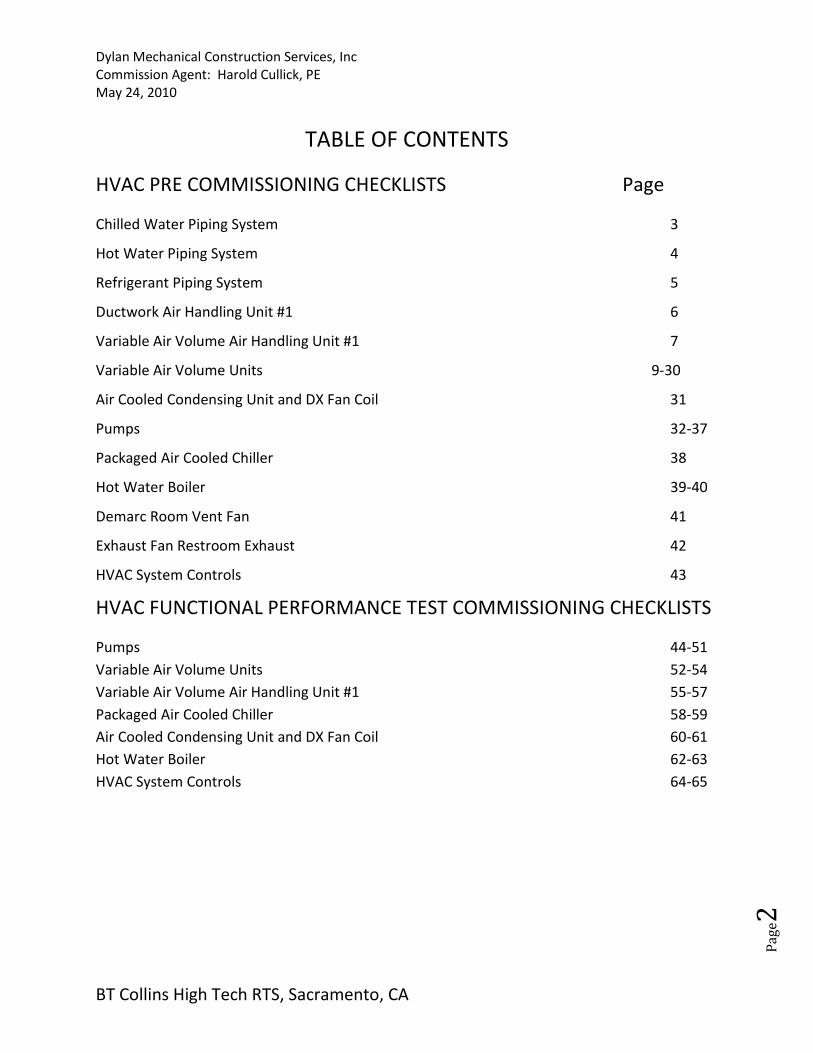
TABLE OF CONTENTS
HVAC PRE COMMISSIONING CHECKLISTS Page
Chilled Water Piping System 3
Hot Water Piping System 4
Refrigerant Piping System 5
Ductwork Air Handling Unit #1 6
Variable Air Volume Air Handling Unit #1 7
Variable Air Volume Units 9-30
Air Cooled Condensing Unit and DX Fan Coil 31
Pumps 32-37
Packaged Air Cooled Chiller 38
Hot Water Boiler 39-40
Demarc Room Vent Fan 41
Exhaust Fan Restroom Exhaust 42
HVAC System Controls 43
HVAC FUNCTIONAL PERFORMANCE TEST COMMISSIONING CHECKLISTS
Pumps 44-51
Variable Air Volume Units 52-54
Variable Air Volume Air Handling Unit #1 55-57
Packaged Air Cooled Chiller 58-59
Air Cooled Condensing Unit and DX Fan Coil 60-61
Hot Water Boiler 62-63
HVAC System Controls 64-65
Dylan Mechanical Construction Services, Inc
Commission Agent: Harold Cullick, PE
May 24, 2010
BT Collins High Tech RTS, Sacramento, CA
Pa
ge3
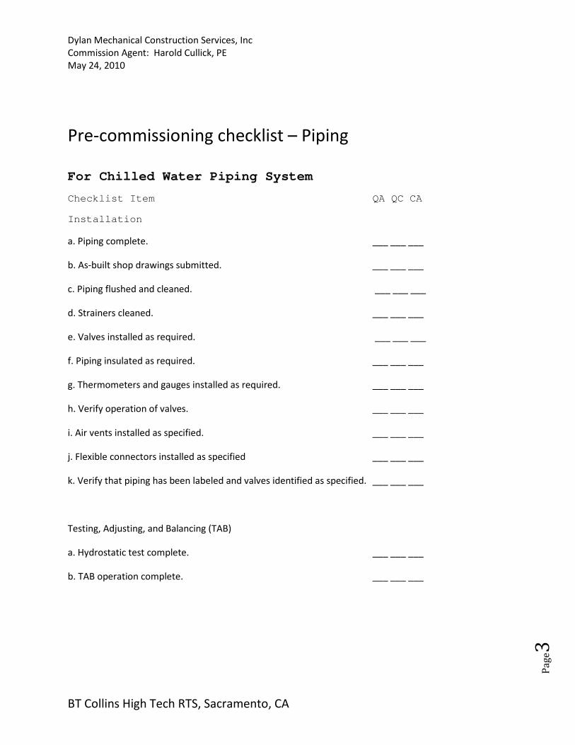
Pre-commissioning checklist – Piping
For Chilled Water Piping System Checklist Item QA QC CA Installation
a. Piping complete. ___ ___ ___
b. As-built shop drawings submitted. ___ ___ ___
c. Piping flushed and cleaned. ___ ___ ___
d. Strainers cleaned. ___ ___ ___
e. Valves installed as required. ___ ___ ___
f. Piping insulated as required. ___ ___ ___
g. Thermometers and gauges installed as required. ___ ___ ___
h. Verify operation of valves. ___ ___ ___
i. Air vents installed as specified. ___ ___ ___
j. Flexible connectors installed as specified ___ ___ ___
k. Verify that piping has been labeled and valves identified as specified. ___ ___ ___
Testing, Adjusting, and Balancing (TAB)
a. Hydrostatic test complete. ___ ___ ___
b. TAB operation complete. ___ ___ ___

Dylan Mechanical Construction Services, Inc
Commission Agent: Harold Cullick, PE
May 24, 2010
BT Collins High Tech RTS, Sacramento, CA
Pa
ge4
Pre-commissioning checklist – Piping
For Hot Water Piping System Checklist Item QA QC CA Installation
a. Piping complete. ___ ___ ___
b. As-built shop drawings submitted. ___ ___ ___
c. Piping flushed and cleaned. ___ ___ ___
d. Strainers cleaned. ___ ___ ___
e. Valves installed as required. ___ ___ ___
f. Piping insulated as required. ___ ___ ___
g. Thermometers and gauges installed as required. ___ ___ ___
h. Verify operation of valves. ___ ___ ___
i. Air vents installed as specified. ___ ___ ___
j. Flexible connectors installed as specified ___ ___ ___
k. Verify that piping has been labeled and valves identified as specified. ___ ___ ___
Testing, Adjusting, and Balancing (TAB)
a. Hydrostatic test complete. ___ ___ ___
b. TAB operation complete. ___ ___ ___
Dylan Mechanical Construction Services, Inc
Commission Agent: Harold Cullick, PE
May 24, 2010
BT Collins High Tech RTS, Sacramento, CA
Pa
ge5
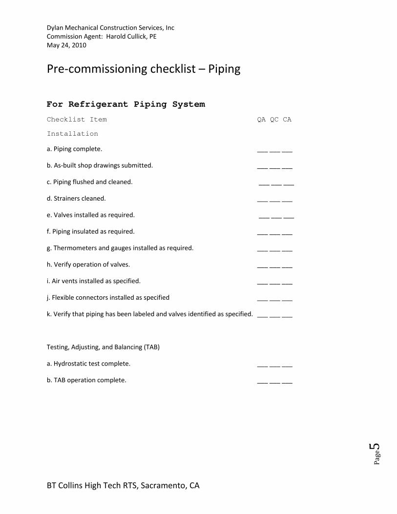
Pre-commissioning checklist – Piping
For Refrigerant Piping System Checklist Item QA QC CA Installation
a. Piping complete. ___ ___ ___
b. As-built shop drawings submitted. ___ ___ ___
c. Piping flushed and cleaned. ___ ___ ___
d. Strainers cleaned. ___ ___ ___
e. Valves installed as required. ___ ___ ___
f. Piping insulated as required. ___ ___ ___
g. Thermometers and gauges installed as required. ___ ___ ___
h. Verify operation of valves. ___ ___ ___
i. Air vents installed as specified. ___ ___ ___
j. Flexible connectors installed as specified ___ ___ ___
k. Verify that piping has been labeled and valves identified as specified. ___ ___ ___
Testing, Adjusting, and Balancing (TAB)
a. Hydrostatic test complete. ___ ___ ___
b. TAB operation complete. ___ ___ ___
Dylan Mechanical Construction Services, Inc
Commission Agent: Harold Cullick, PE
May 24, 2010
BT Collins High Tech RTS, Sacramento, CA
Pa
ge6
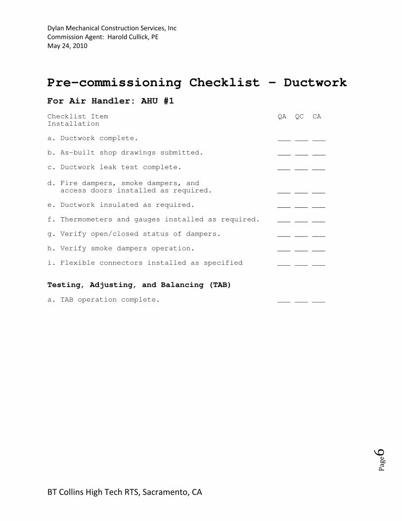
Pre-commissioning Checklist – Ductwork
For Air Handler: AHU #1 Checklist Item QA QC CA Installation a. Ductwork complete. ___ ___ ___ b. As-built shop drawings submitted. ___ ___ ___ c. Ductwork leak test complete. ___ ___ ___
d. Fire dampers, smoke dampers, and access doors installed as required. ___ ___ ___ e. Ductwork insulated as required. ___ ___ ___ f. Thermometers and gauges installed as required. ___ ___ ___ g. Verify open/closed status of dampers. ___ ___ ___ h. Verify smoke dampers operation. ___ ___ ___ i. Flexible connectors installed as specified ___ ___ ___
Testing, Adjusting, and Balancing (TAB) a. TAB operation complete. ___ ___ ___
Dylan Mechanical Construction Services, Inc
Commission Agent: Harold Cullick, PE
May 24, 2010
BT Collins High Tech RTS, Sacramento, CA
Pa
ge7
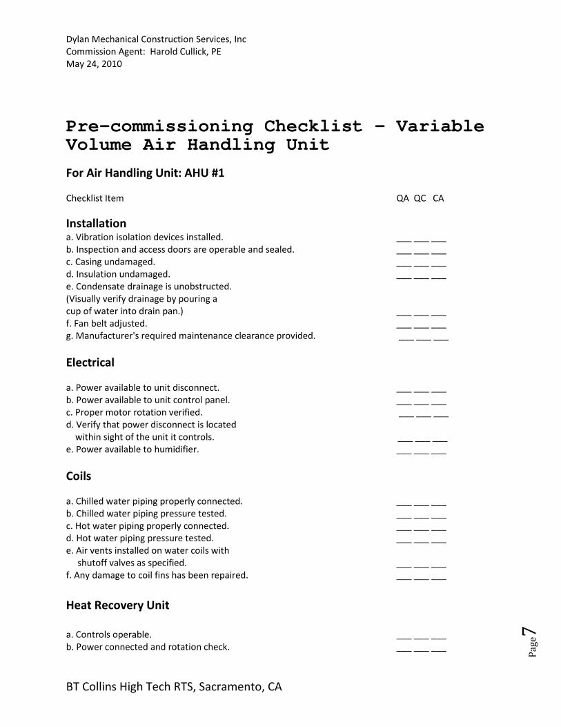
Pre-commissioning Checklist - Variable Volume Air Handling Unit
For Air Handling Unit: AHU #1
Checklist Item QA QC CA
Installation a. Vibration isolation devices installed. ___ ___ ___
b. Inspection and access doors are operable and sealed. ___ ___ ___
c. Casing undamaged. ___ ___ ___
d. Insulation undamaged. ___ ___ ___
e. Condensate drainage is unobstructed.
(Visually verify drainage by pouring a
cup of water into drain pan.) ___ ___ ___
f. Fan belt adjusted. ___ ___ ___
g. Manufacturer's required maintenance clearance provided. ___ ___ ___
Electrical
a. Power available to unit disconnect. ___ ___ ___
b. Power available to unit control panel. ___ ___ ___
c. Proper motor rotation verified. ___ ___ ___
d. Verify that power disconnect is located
within sight of the unit it controls. ___ ___ ___
e. Power available to humidifier. ___ ___ ___
Coils
a. Chilled water piping properly connected. ___ ___ ___
b. Chilled water piping pressure tested. ___ ___ ___
c. Hot water piping properly connected. ___ ___ ___
d. Hot water piping pressure tested. ___ ___ ___
e. Air vents installed on water coils with
shutoff valves as specified. ___ ___ ___
f. Any damage to coil fins has been repaired. ___ ___ ___
Heat Recovery Unit
a. Controls operable. ___ ___ ___
b. Power connected and rotation check. ___ ___ ___
Dylan Mechanical Construction Services, Inc
Commission Agent: Harold Cullick, PE
May 24, 2010
BT Collins High Tech RTS, Sacramento, CA
Pa
ge8
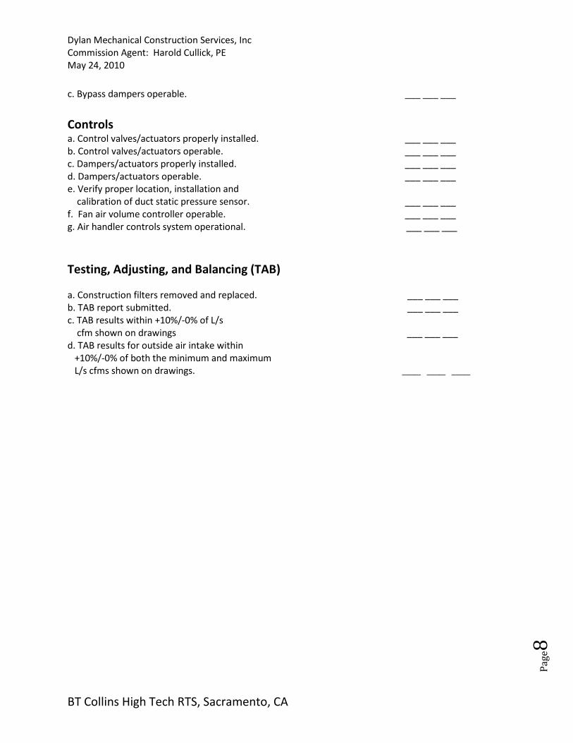
c. Bypass dampers operable. ___ ___ ___
Controls
a. Control valves/actuators properly installed. ___ ___ ___
b. Control valves/actuators operable. ___ ___ ___
c. Dampers/actuators properly installed. ___ ___ ___
d. Dampers/actuators operable. ___ ___ ___
e. Verify proper location, installation and
calibration of duct static pressure sensor. ___ ___ ___
f. Fan air volume controller operable. ___ ___ ___
g. Air handler controls system operational. ___ ___ ___
Testing, Adjusting, and Balancing (TAB)
a. Construction filters removed and replaced. ___ ___ ___
b. TAB report submitted. ___ ___ ___
c. TAB results within +10%/-0% of L/s
cfm shown on drawings ___ ___ ___
d. TAB results for outside air intake within
+10%/-0% of both the minimum and maximum
L/s cfms shown on drawings. ___ ___ ___
Dylan Mechanical Construction Services, Inc
Commission Agent: Harold Cullick, PE
May 24, 2010
BT Collins High Tech RTS, Sacramento, CA
Pa
ge9
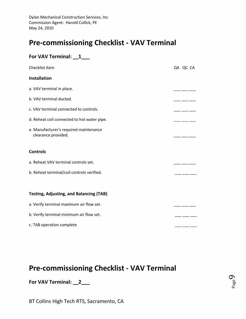
Pre-commissioning Checklist - VAV Terminal
For VAV Terminal: __1___
Checklist Item QA QC CA
Installation
a. VAV terminal in place. ___ ___ ___
b. VAV terminal ducted. ___ ___ ___
c. VAV terminal connected to controls. ___ ___ ___
d. Reheat coil connected to hot water pipe. ___ ___ ___
e. Manufacturer's required maintenance
clearance provided. ___ ___ ___
Controls
a. Reheat VAV terminal controls set. ___ ___ ___
b. Reheat terminal/coil controls verified. ___ ___ ___
Testing, Adjusting, and Balancing (TAB)
a. Verify terminal maximum air flow set. ___ ___ ___
b. Verify terminal minimum air flow set. ___ ___ ___
c. TAB operation complete ___ ___ ___
Pre-commissioning Checklist - VAV Terminal
For VAV Terminal: __2___

Dylan Mechanical Construction Services, Inc
Commission Agent: Harold Cullick, PE
May 24, 2010
BT Collins High Tech RTS, Sacramento, CA
Pa
ge1
0
Checklist Item QA QC CA
Installation
a. VAV terminal in place. ___ ___ ___
b. VAV terminal ducted. ___ ___ ___
c. VAV terminal connected to controls. ___ ___ ___
d. Reheat coil connected to hot water pipe. ___ ___ ___
e. Manufacturer's required maintenance
clearance provided. ___ ___ ___
Controls
a. Reheat VAV terminal controls set. ___ ___ ___
b. Reheat terminal/coil controls verified. ___ ___ ___
Testing, Adjusting, and Balancing (TAB)
a. Verify terminal maximum air flow set. ___ ___ ___
b. Verify terminal minimum air flow set. ___ ___ ___
c. TAB operation complete. ___ ___ ___

Dylan Mechanical Construction Services, Inc
Commission Agent: Harold Cullick, PE
May 24, 2010
BT Collins High Tech RTS, Sacramento, CA
Pa
ge1
1
Pre-commissioning Checklist - VAV Terminal
For VAV Terminal: __3___
Checklist Item QA QC CA
Installation
a. VAV terminal in place. ___ ___ ___
b. VAV terminal ducted. ___ ___ ___
c. VAV terminal connected to controls. ___ ___ ___
d. Reheat coil connected to hot water pipe. ___ ___ ___
e. Manufacturer's required maintenance
clearance provided. ___ ___ ___
Controls
a. Reheat VAV terminal controls set. ___ ___ ___
b. Reheat terminal/coil controls verified. ___ ___ ___
Testing, Adjusting, and Balancing (TAB)
a. Verify terminal maximum air flow set. ___ ___ ___
b. Verify terminal minimum air flow set. ___ ___ ___
c. TAB operation complete. ___ ___ ___

Dylan Mechanical Construction Services, Inc
Commission Agent: Harold Cullick, PE
May 24, 2010
BT Collins High Tech RTS, Sacramento, CA
Pa
ge1
2
Pre-commissioning Checklist - VAV Terminal
For VAV Terminal: __4___
Checklist Item QA QC CA
Installation
a. VAV terminal in place. ___ ___ ___
b. VAV terminal ducted. ___ ___ ___
c. VAV terminal connected to controls. ___ ___ ___
d. Reheat coil connected to hot water pipe. ___ ___ ___
e. Manufacturer's required maintenance
clearance provided. ___ ___ ___
Controls
a. Reheat VAV terminal controls set. ___ ___ ___
b. Reheat terminal/coil controls verified. ___ ___ ___
Testing, Adjusting, and Balancing (TAB)
a. Verify terminal maximum air flow set. ___ ___ ___
b. Verify terminal minimum air flow set. ___ ___ ___
c. TAB operation complete. ___ ___ ___

Dylan Mechanical Construction Services, Inc
Commission Agent: Harold Cullick, PE
May 24, 2010
BT Collins High Tech RTS, Sacramento, CA
Pa
ge1
3
Pre-commissioning Checklist - VAV Terminal
For VAV Terminal: __5___
Checklist Item QA QC CA
Installation
a. VAV terminal in place. ___ ___ ___
b. VAV terminal ducted. ___ ___ ___
c. VAV terminal connected to controls. ___ ___ ___
d. Reheat coil connected to hot water pipe. ___ ___ ___
e. Manufacturer's required maintenance
clearance provided. ___ ___ ___
Controls
a. Reheat VAV terminal controls set. ___ ___ ___
b. Reheat terminal/coil controls verified. ___ ___ ___
Testing, Adjusting, and Balancing (TAB)
a. Verify terminal maximum air flow set. ___ ___ ___
b. Verify terminal minimum air flow set. ___ ___ ___
c. TAB operation complete. ___ ___ ___

Dylan Mechanical Construction Services, Inc
Commission Agent: Harold Cullick, PE
May 24, 2010
BT Collins High Tech RTS, Sacramento, CA
Pa
ge1
4
Pre-commissioning Checklist - VAV Terminal
For VAV Terminal: __6___
Checklist Item QA QC CA
Installation
a. VAV terminal in place. ___ ___ ___
b. VAV terminal ducted. ___ ___ ___
c. VAV terminal connected to controls. ___ ___ ___
d. Reheat coil connected to hot water pipe. ___ ___ ___
e. Manufacturer's required maintenance
clearance provided. ___ ___ ___
Controls
a. Reheat VAV terminal controls set. ___ ___ ___
b. Reheat terminal/coil controls verified. ___ ___ ___
Testing, Adjusting, and Balancing (TAB)
a. Verify terminal maximum air flow set. ___ ___ ___
b. Verify terminal minimum air flow set. ___ ___ ___
c. TAB operation complete. ___ ___ ___

Dylan Mechanical Construction Services, Inc
Commission Agent: Harold Cullick, PE
May 24, 2010
BT Collins High Tech RTS, Sacramento, CA
Pa
ge1
5
Pre-commissioning Checklist - VAV Terminal
For VAV Terminal: __7___
Checklist Item QA QC CA
Installation
a. VAV terminal in place. ___ ___ ___
b. VAV terminal ducted. ___ ___ ___
c. VAV terminal connected to controls. ___ ___ ___
d. Reheat coil connected to hot water pipe. ___ ___ ___
e. Manufacturer's required maintenance
clearance provided. ___ ___ ___
Controls
a. Reheat VAV terminal controls set. ___ ___ ___
b. Reheat terminal/coil controls verified. ___ ___ ___
Testing, Adjusting, and Balancing (TAB)
a. Verify terminal maximum air flow set. ___ ___ ___
b. Verify terminal minimum air flow set. ___ ___ ___
c. TAB operation complete. ___ ___ ___

Dylan Mechanical Construction Services, Inc
Commission Agent: Harold Cullick, PE
May 24, 2010
BT Collins High Tech RTS, Sacramento, CA
Pa
ge1
6
Pre-commissioning Checklist - VAV Terminal
For VAV Terminal: __8___
Checklist Item QA QC CA
Installation
a. VAV terminal in place. ___ ___ ___
b. VAV terminal ducted. ___ ___ ___
c. VAV terminal connected to controls. ___ ___ ___
d. Reheat coil connected to hot water pipe. ___ ___ ___
e. Manufacturer's required maintenance
clearance provided. ___ ___ ___
Controls
a. Reheat VAV terminal controls set. ___ ___ ___
b. Reheat terminal/coil controls verified. ___ ___ ___
Testing, Adjusting, and Balancing (TAB)
a. Verify terminal maximum air flow set. ___ ___ ___
b. Verify terminal minimum air flow set. ___ ___ ___
c. TAB operation complete. ___ ___ ___

Dylan Mechanical Construction Services, Inc
Commission Agent: Harold Cullick, PE
May 24, 2010
BT Collins High Tech RTS, Sacramento, CA
Pa
ge1
7
Pre-commissioning Checklist - VAV Terminal
For VAV Terminal: __9___
Checklist Item QA QC CA
Installation
a. VAV terminal in place. ___ ___ ___
b. VAV terminal ducted. ___ ___ ___
c. VAV terminal connected to controls. ___ ___ ___
d. Reheat coil connected to hot water pipe. ___ ___ ___
e. Manufacturer's required maintenance
clearance provided. ___ ___ ___
Controls
a. Reheat VAV terminal controls set. ___ ___ ___
b. Reheat terminal/coil controls verified. ___ ___ ___
Testing, Adjusting, and Balancing (TAB)
a. Verify terminal maximum air flow set. ___ ___ ___
b. Verify terminal minimum air flow set. ___ ___ ___
c. TAB operation complete. ___ ___ ___
Dylan Mechanical Construction Services, Inc
Commission Agent: Harold Cullick, PE
May 24, 2010
BT Collins High Tech RTS, Sacramento, CA
Pa
ge1
8
Pre-commissioning Checklist - VAV Terminal
For VAV Terminal: __10___
Checklist Item QA QC CA
Installation
a. VAV terminal in place. ___ ___ ___
b. VAV terminal ducted. ___ ___ ___
c. VAV terminal connected to controls. ___ ___ ___
d. Reheat coil connected to hot water pipe. ___ ___ ___
e. Manufacturer's required maintenance
clearance provided. ___ ___ ___
Controls
a. Reheat VAV terminal controls set. ___ ___ ___
b. Reheat terminal/coil controls verified. ___ ___ ___
Testing, Adjusting, and Balancing (TAB)
a. Verify terminal maximum air flow set. ___ ___ ___
b. Verify terminal minimum air flow set. ___ ___ ___
c. TAB operation complete. ___ ___ ___

Dylan Mechanical Construction Services, Inc
Commission Agent: Harold Cullick, PE
May 24, 2010
BT Collins High Tech RTS, Sacramento, CA
Pa
ge1
9
Pre-commissioning Checklist - VAV Terminal
For VAV Terminal: __11___
Checklist Item QA QC CA
Installation
a. VAV terminal in place. ___ ___ ___
b. VAV terminal ducted. ___ ___ ___
c. VAV terminal connected to controls. ___ ___ ___
d. Reheat coil connected to hot water pipe. ___ ___ ___
e. Manufacturer's required maintenance
clearance provided. ___ ___ ___
Controls
a. Reheat VAV terminal controls set. ___ ___ ___
b. Reheat terminal/coil controls verified. ___ ___ ___
Testing, Adjusting, and Balancing (TAB)
a. Verify terminal maximum air flow set. ___ ___ ___
b. Verify terminal minimum air flow set. ___ ___ ___
c. TAB operation complete. ___ ___ ___

Dylan Mechanical Construction Services, Inc
Commission Agent: Harold Cullick, PE
May 24, 2010
BT Collins High Tech RTS, Sacramento, CA
Pa
ge2
0
Pre-commissioning Checklist - VAV Terminal
For VAV Terminal: __12___
Checklist Item QA QC CA
Installation
a. VAV terminal in place. ___ ___ ___
b. VAV terminal ducted. ___ ___ ___
c. VAV terminal connected to controls. ___ ___ ___
d. Reheat coil connected to hot water pipe. ___ ___ ___
e. Manufacturer's required maintenance
clearance provided. ___ ___ ___
Controls
a. Reheat VAV terminal controls set. ___ ___ ___
b. Reheat terminal/coil controls verified. ___ ___ ___
Testing, Adjusting, and Balancing (TAB)
a. Verify terminal maximum air flow set. ___ ___ ___
b. Verify terminal minimum air flow set. ___ ___ ___
c. TAB operation complete. ___ ___ ___

Dylan Mechanical Construction Services, Inc
Commission Agent: Harold Cullick, PE
May 24, 2010
BT Collins High Tech RTS, Sacramento, CA
Pa
ge2
1
Pre-commissioning Checklist - VAV Terminal
For VAV Terminal: __13___
Checklist Item QA QC CA
Installation
a. VAV terminal in place. ___ ___ ___
b. VAV terminal ducted. ___ ___ ___
c. VAV terminal connected to controls. ___ ___ ___
d. Reheat coil connected to hot water pipe. ___ ___ ___
e. Manufacturer's required maintenance
clearance provided. ___ ___ ___
Controls
a. Reheat VAV terminal controls set. ___ ___ ___
b. Reheat terminal/coil controls verified. ___ ___ ___
Testing, Adjusting, and Balancing (TAB)
a. Verify terminal maximum air flow set. ___ ___ ___
b. Verify terminal minimum air flow set. ___ ___ ___
c. TAB operation complete. ___ ___ ___

Dylan Mechanical Construction Services, Inc
Commission Agent: Harold Cullick, PE
May 24, 2010
BT Collins High Tech RTS, Sacramento, CA
Pa
ge2
2
Pre-commissioning Checklist - VAV Terminal
For VAV Terminal: __14___
Checklist Item QA QC CA
Installation
a. VAV terminal in place. ___ ___ ___
b. VAV terminal ducted. ___ ___ ___
c. VAV terminal connected to controls. ___ ___ ___
d. Reheat coil connected to hot water pipe. ___ ___ ___
e. Manufacturer's required maintenance
clearance provided. ___ ___ ___
Controls
a. Reheat VAV terminal controls set. ___ ___ ___
b. Reheat terminal/coil controls verified. ___ ___ ___
Testing, Adjusting, and Balancing (TAB)
a. Verify terminal maximum air flow set. ___ ___ ___
b. Verify terminal minimum air flow set. ___ ___ ___
c. TAB operation complete. ___ ___ ___

Dylan Mechanical Construction Services, Inc
Commission Agent: Harold Cullick, PE
May 24, 2010
BT Collins High Tech RTS, Sacramento, CA
Pa
ge2
3
Pre-commissioning Checklist - VAV Terminal
For VAV Terminal: __15___
Checklist Item QA QC CA
Installation
a. VAV terminal in place. ___ ___ ___
b. VAV terminal ducted. ___ ___ ___
c. VAV terminal connected to controls. ___ ___ ___
d. Reheat coil connected to hot water pipe. ___ ___ ___
e. Manufacturer's required maintenance
clearance provided. ___ ___ ___
Controls
a. Reheat VAV terminal controls set. ___ ___ ___
b. Reheat terminal/coil controls verified. ___ ___ ___
Testing, Adjusting, and Balancing (TAB)
a. Verify terminal maximum air flow set. ___ ___ ___
b. Verify terminal minimum air flow set. ___ ___ ___
c. TAB operation complete. ___ ___ ___

Dylan Mechanical Construction Services, Inc
Commission Agent: Harold Cullick, PE
May 24, 2010
BT Collins High Tech RTS, Sacramento, CA
Pa
ge2
4
Pre-commissioning Checklist - VAV Terminal
For VAV Terminal: __16___
Checklist Item QA QC CA
Installation
a. VAV terminal in place. ___ ___ ___
b. VAV terminal ducted. ___ ___ ___
c. VAV terminal connected to controls. ___ ___ ___
d. Reheat coil connected to hot water pipe. ___ ___ ___
e. Manufacturer's required maintenance
clearance provided. ___ ___ ___
Controls
a. Reheat VAV terminal controls set. ___ ___ ___
b. Reheat terminal/coil controls verified. ___ ___ ___
Testing, Adjusting, and Balancing (TAB)
a. Verify terminal maximum air flow set. ___ ___ ___
b. Verify terminal minimum air flow set. ___ ___ ___
c. TAB operation complete. ___ ___ ___

Dylan Mechanical Construction Services, Inc
Commission Agent: Harold Cullick, PE
May 24, 2010
BT Collins High Tech RTS, Sacramento, CA
Pa
ge2
5
Pre-commissioning Checklist - VAV Terminal
For VAV Terminal: __17___
Checklist Item QA QC CA
Installation
a. VAV terminal in place. ___ ___ ___
b. VAV terminal ducted. ___ ___ ___
c. VAV terminal connected to controls. ___ ___ ___
d. Reheat coil connected to hot water pipe. ___ ___ ___
e. Manufacturer's required maintenance
clearance provided. ___ ___ ___
Controls
a. Reheat VAV terminal controls set. ___ ___ ___
b. Reheat terminal/coil controls verified. ___ ___ ___
Testing, Adjusting, and Balancing (TAB)
a. Verify terminal maximum air flow set. ___ ___ ___
b. Verify terminal minimum air flow set. ___ ___ ___
c. TAB operation complete. ___ ___ ___

Dylan Mechanical Construction Services, Inc
Commission Agent: Harold Cullick, PE
May 24, 2010
BT Collins High Tech RTS, Sacramento, CA
Pa
ge2
6
Pre-commissioning Checklist - VAV Terminal
For VAV Terminal: __18__
Checklist Item QA QC CA
Installation
a. VAV terminal in place. ___ ___ ___
b. VAV terminal ducted. ___ ___ ___
c. VAV terminal connected to controls. ___ ___ ___
d. Reheat coil connected to hot water pipe. ___ ___ ___
e. Manufacturer's required maintenance
clearance provided. ___ ___ ___
Controls
a. Reheat VAV terminal controls set. ___ ___ ___
b. Reheat terminal/coil controls verified. ___ ___ ___
Testing, Adjusting, and Balancing (TAB)
a. Verify terminal maximum air flow set. ___ ___ ___
b. Verify terminal minimum air flow set. ___ ___ ___
c. TAB operation complete. ___ ___ ___

Dylan Mechanical Construction Services, Inc
Commission Agent: Harold Cullick, PE
May 24, 2010
BT Collins High Tech RTS, Sacramento, CA
Pa
ge2
7
Pre-commissioning Checklist - VAV Terminal
For VAV Terminal: __19__
Checklist Item QA QC CA
Installation
a. VAV terminal in place. ___ ___ ___
b. VAV terminal ducted. ___ ___ ___
c. VAV terminal connected to controls. ___ ___ ___
d. Reheat coil connected to hot water pipe. ___ ___ ___
e. Manufacturer's required maintenance
clearance provided. ___ ___ ___
Controls
a. Reheat VAV terminal controls set. ___ ___ ___
b. Reheat terminal/coil controls verified. ___ ___ ___
Testing, Adjusting, and Balancing (TAB)
a. Verify terminal maximum air flow set. ___ ___ ___
b. Verify terminal minimum air flow set. ___ ___ ___
c. TAB operation complete. ___ ___ ___

Dylan Mechanical Construction Services, Inc
Commission Agent: Harold Cullick, PE
May 24, 2010
BT Collins High Tech RTS, Sacramento, CA
Pa
ge2
8
Pre-commissioning Checklist - VAV Terminal
For VAV Terminal: __20___
Checklist Item QA QC CA
Installation
a. VAV terminal in place. ___ ___ ___
b. VAV terminal ducted. ___ ___ ___
c. VAV terminal connected to controls. ___ ___ ___
d. Reheat coil connected to hot water pipe. ___ ___ ___
e. Manufacturer's required maintenance
clearance provided. ___ ___ ___
Controls
a. Reheat VAV terminal controls set. ___ ___ ___
b. Reheat terminal/coil controls verified. ___ ___ ___
Testing, Adjusting, and Balancing (TAB)
a. Verify terminal maximum air flow set. ___ ___ ___
b. Verify terminal minimum air flow set. ___ ___ ___
c. TAB operation complete. ___ ___ ___

Dylan Mechanical Construction Services, Inc
Commission Agent: Harold Cullick, PE
May 24, 2010
BT Collins High Tech RTS, Sacramento, CA
Pa
ge2
9
Pre-commissioning Checklist - VAV Terminal
For VAV Terminal: __21___
Checklist Item QA QC CA
Installation
a. VAV terminal in place. ___ ___ ___
b. VAV terminal ducted. ___ ___ ___
c. VAV terminal connected to controls. ___ ___ ___
d. Reheat coil connected to hot water pipe. ___ ___ ___
e. Manufacturer's required maintenance
clearance provided. ___ ___ ___
Controls
a. Reheat VAV terminal controls set. ___ ___ ___
b. Reheat terminal/coil controls verified. ___ ___ ___
Testing, Adjusting, and Balancing (TAB)
a. Verify terminal maximum air flow set. ___ ___ ___
b. Verify terminal minimum air flow set. ___ ___ ___
c. TAB operation complete. ___ ___ ___

Dylan Mechanical Construction Services, Inc
Commission Agent: Harold Cullick, PE
May 24, 2010
BT Collins High Tech RTS, Sacramento, CA
Pa
ge3
0
Pre-commissioning Checklist - VAV Terminal
For VAV Terminal: __22___
Checklist Item QA QC CA
Installation
a. VAV terminal in place. ___ ___ ___
b. VAV terminal ducted. ___ ___ ___
c. VAV terminal connected to controls. ___ ___ ___
d. Reheat coil connected to hot water pipe. ___ ___ ___
e. Manufacturer's required maintenance
clearance provided. ___ ___ ___
Controls
a. Reheat VAV terminal controls set. ___ ___ ___
b. Reheat terminal/coil controls verified. ___ ___ ___
Testing, Adjusting, and Balancing (TAB)
a. Verify terminal maximum air flow set. ___ ___ ___
b. Verify terminal minimum air flow set. ___ ___ ___
c. TAB operation complete. ___ ___ ___
Dylan Mechanical Construction Services, Inc
Commission Agent: Harold Cullick, PE
May 24, 2010
BT Collins High Tech RTS, Sacramento, CA
Pa
ge3
1
Pre-commissioning Checklist - DX Air Cooled Condensing
Unit
For Condensing Unit: CU-1 and AC-1 for the Demarcation Room
Checklist Item QA QC CA
Installation ___ ___ ___
b. Refrigerant pipe leak tested. ___ ___ ___
c. Refrigerant pipe evacuated and charged ___ ___ ___
in accordance with manufacturer's instructions.
d. Check condenser fans for proper rotation. ___ ___ ___
e. Any damage to coil fins has been repaired. ___ ___ ___
f. Manufacturer's required maintenance/ ___ ___ ___
operational clearance provided.
Electrical
a. Power available to unit disconnect. ___ ___ ___
b. Power available to unit control panel. ___ ___ ___
c. Verify that power disconnect is located
within sight of the unit it controls ___ ___ ___
Controls
a. Unit safety/protection devices tested. ___ ___ ___
b. Control system and interlocks installed. ___ ___ ___
c. Control system and interlocks operational. ___ ___ ___
Dylan Mechanical Construction Services, Inc
Commission Agent: Harold Cullick, PE
May 24, 2010
BT Collins High Tech RTS, Sacramento, CA
Pa
ge3
2
Pre-commissioning Checklist – Pumps
For Pump: P-1A Hot Water Pump
Checklist Item QA QC CA
Installation
a. Pumps grouted in place. ___ ___ ___
b. Pump vibration isolation devices functional. ___ ___ ___
c. Pump/motor coupling alignment verified. ___ ___ ___
d. Piping system installed. ___ ___ ___
e. Piping system pressure tested. ___ ___ ___
f. Pump not leaking. ___ ___ ___
g. Field assembled couplings aligned to
meet manufacturer's prescribed tolerances. ___ ___ ___
Electrical
a. Power available to pump disconnect. ___ ___ ___
b. Pump rotation verified. ___ ___ ___
c. Control system interlocks functional. ___ ___ ___
d. Verify that power disconnect is located
within sight of the unit it controls. ___ ___ ___
Testing, Adjusting, and Balancing (TAB)
a. Pressure/temperature gauges installed. ___ ___ ___
b. Piping system cleaned. ___ ___ ___
c. Chemical water treatment complete. ___ ___ ___
d. Water balance complete. ___ ___ ___
e. Water balance with design maximum flow. ___ ___ ___
f. TAB Report submitted. ___ ___ ___
Dylan Mechanical Construction Services, Inc
Commission Agent: Harold Cullick, PE
May 24, 2010
BT Collins High Tech RTS, Sacramento, CA
Pa
ge3
3
Pre-commissioning Checklist – Pumps
For Pump: P-1B Hot Water Pump
Checklist Item QA QC CA
Installation
a. Pumps grouted in place. ___ ___ ___
b. Pump vibration isolation devices functional. ___ ___ ___
c. Pump/motor coupling alignment verified. ___ ___ ___
d. Piping system installed. ___ ___ ___
e. Piping system pressure tested. ___ ___ ___
f. Pump not leaking. ___ ___ ___
g. Field assembled couplings aligned to
meet manufacturer's prescribed tolerances. ___ ___ ___
Electrical
a. Power available to pump disconnect. ___ ___ ___
b. Pump rotation verified. ___ ___ ___
c. Control system interlocks functional. ___ ___ ___
d. Verify that power disconnect is located
within sight of the unit it controls. ___ ___ ___
Testing, Adjusting, and Balancing (TAB)
a. Pressure/temperature gauges installed. ___ ___ ___
b. Piping system cleaned. ___ ___ ___
c. Chemical water treatment complete. ___ ___ ___
d. Water balance complete. ___ ___ ___
e. Water balance with design maximum flow. ___ ___ ___
f. TAB Report submitted. ___ ___ ___

Dylan Mechanical Construction Services, Inc
Commission Agent: Harold Cullick, PE
May 24, 2010
BT Collins High Tech RTS, Sacramento, CA
Pa
ge3
4
Pre-commissioning Checklist – Pumps
For Pump: P-2A Chilled Water Pump
Checklist Item QA QC CA
Installation
a. Pumps grouted in place. ___ ___ ___
b. Pump vibration isolation devices functional. ___ ___ ___
c. Pump/motor coupling alignment verified. ___ ___ ___
d. Piping system installed. ___ ___ ___
e. Piping system pressure tested. ___ ___ ___
f. Pump not leaking. ___ ___ ___
g. Field assembled couplings aligned to
meet manufacturer's prescribed tolerances. ___ ___ ___
Electrical
a. Power available to pump disconnect. ___ ___ ___
b. Pump rotation verified. ___ ___ ___
c. Control system interlocks functional. ___ ___ ___
d. Verify that power disconnect is located
within sight of the unit it controls. ___ ___ ___
Testing, Adjusting, and Balancing (TAB)
a. Pressure/temperature gauges installed. ___ ___ ___
b. Piping system cleaned. ___ ___ ___
c. Chemical water treatment complete. ___ ___ ___
d. Water balance complete. ___ ___ ___
e. Water balance with design maximum flow. ___ ___ ___
f. TAB Report submitted. ___ ___ ___

Dylan Mechanical Construction Services, Inc
Commission Agent: Harold Cullick, PE
May 24, 2010
BT Collins High Tech RTS, Sacramento, CA
Pa
ge3
5
Pre-commissioning Checklist – Pumps
For Pump: P-2B Chilled Water Pump
Checklist Item QA QC CA
Installation
a. Pumps grouted in place. ___ ___ ___
b. Pump vibration isolation devices functional. ___ ___ ___
c. Pump/motor coupling alignment verified. ___ ___ ___
d. Piping system installed. ___ ___ ___
e. Piping system pressure tested. ___ ___ ___
f. Pump not leaking. ___ ___ ___
g. Field assembled couplings aligned to
meet manufacturer's prescribed tolerances. ___ ___ ___
Electrical
a. Power available to pump disconnect. ___ ___ ___
b. Pump rotation verified. ___ ___ ___
c. Control system interlocks functional. ___ ___ ___
d. Verify that power disconnect is located
within sight of the unit it controls. ___ ___ ___
Testing, Adjusting, and Balancing (TAB)
a. Pressure/temperature gauges installed. ___ ___ ___
b. Piping system cleaned. ___ ___ ___
c. Chemical water treatment complete. ___ ___ ___
d. Water balance complete. ___ ___ ___
e. Water balance with design maximum flow. ___ ___ ___
f. TAB Report submitted. ___ ___ ___

Dylan Mechanical Construction Services, Inc
Commission Agent: Harold Cullick, PE
May 24, 2010
BT Collins High Tech RTS, Sacramento, CA
Pa
ge3
6
Pre-commissioning Checklist – Pumps
For Pump: P-3A Hot Water Coil Recirc Pump
Checklist Item QA QC CA
Installation
a. Pumps grouted in place. ___ ___ ___
b. Pump vibration isolation devices functional. ___ ___ ___
c. Pump/motor coupling alignment verified. ___ ___ ___
d. Piping system installed. ___ ___ ___
e. Piping system pressure tested. ___ ___ ___
f. Pump not leaking. ___ ___ ___
g. Field assembled couplings aligned to
meet manufacturer's prescribed tolerances. ___ ___ ___
Electrical
a. Power available to pump disconnect. ___ ___ ___
b. Pump rotation verified. ___ ___ ___
c. Control system interlocks functional. ___ ___ ___
d. Verify that power disconnect is located
within sight of the unit it controls. ___ ___ ___
Testing, Adjusting, and Balancing (TAB)
a. Pressure/temperature gauges installed. ___ ___ ___
b. Piping system cleaned. ___ ___ ___
c. Chemical water treatment complete. ___ ___ ___
d. Water balance complete. ___ ___ ___
e. Water balance with design maximum flow. ___ ___ ___
f. TAB Report submitted. ___ ___ ___
Dylan Mechanical Construction Services, Inc
Commission Agent: Harold Cullick, PE
May 24, 2010
BT Collins High Tech RTS, Sacramento, CA
Pa
ge3
7
Pre-commissioning Checklist – Pumps
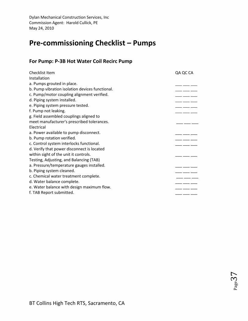
For Pump: P-3B Hot Water Coil Recirc Pump
Checklist Item QA QC CA
Installation
a. Pumps grouted in place. ___ ___ ___
b. Pump vibration isolation devices functional. ___ ___ ___
c. Pump/motor coupling alignment verified. ___ ___ ___
d. Piping system installed. ___ ___ ___
e. Piping system pressure tested. ___ ___ ___
f. Pump not leaking. ___ ___ ___
g. Field assembled couplings aligned to
meet manufacturer's prescribed tolerances. ___ ___ ___
Electrical
a. Power available to pump disconnect. ___ ___ ___
b. Pump rotation verified. ___ ___ ___
c. Control system interlocks functional. ___ ___ ___
d. Verify that power disconnect is located
within sight of the unit it controls. ___ ___ ___
Testing, Adjusting, and Balancing (TAB)
a. Pressure/temperature gauges installed. ___ ___ ___
b. Piping system cleaned. ___ ___ ___
c. Chemical water treatment complete. ___ ___ ___
d. Water balance complete. ___ ___ ___
e. Water balance with design maximum flow. ___ ___ ___
f. TAB Report submitted. ___ ___ ___
Dylan Mechanical Construction Services, Inc
Commission Agent: Harold Cullick, PE
May 24, 2010
BT Collins High Tech RTS, Sacramento, CA
Pa
ge3
8
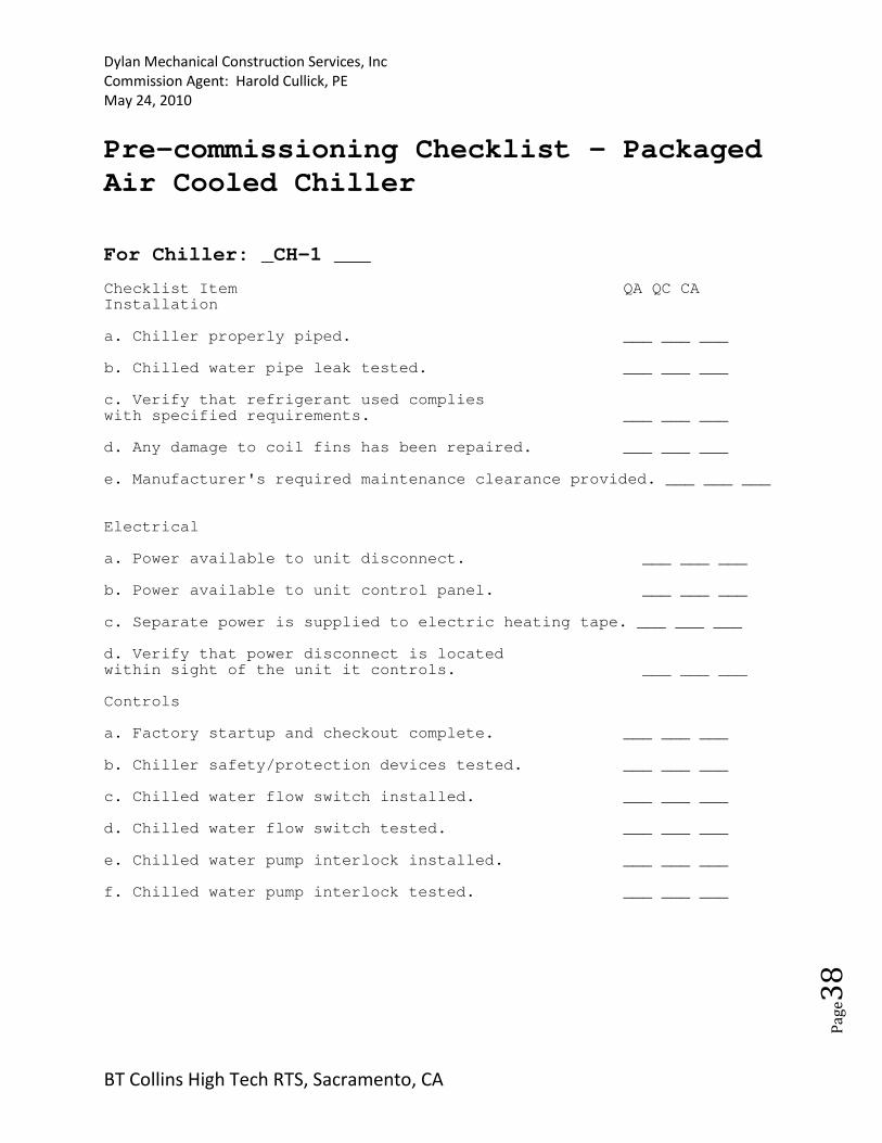
Pre-commissioning Checklist - Packaged
Air Cooled Chiller
For Chiller: _CH-1 ___ Checklist Item QA QC CA Installation a. Chiller properly piped. ___ ___ ___ b. Chilled water pipe leak tested. ___ ___ ___ c. Verify that refrigerant used complies with specified requirements. ___ ___ ___ d. Any damage to coil fins has been repaired. ___ ___ ___ e. Manufacturer's required maintenance clearance provided. ___ ___ ___ Electrical a. Power available to unit disconnect. ___ ___ ___ b. Power available to unit control panel. ___ ___ ___ c. Separate power is supplied to electric heating tape. ___ ___ ___ d. Verify that power disconnect is located within sight of the unit it controls. ___ ___ ___ Controls a. Factory startup and checkout complete. ___ ___ ___ b. Chiller safety/protection devices tested. ___ ___ ___ c. Chilled water flow switch installed. ___ ___ ___ d. Chilled water flow switch tested. ___ ___ ___ e. Chilled water pump interlock installed. ___ ___ ___ f. Chilled water pump interlock tested. ___ ___ ___
Dylan Mechanical Construction Services, Inc
Commission Agent: Harold Cullick, PE
May 24, 2010
BT Collins High Tech RTS, Sacramento, CA
Pa
ge3
9
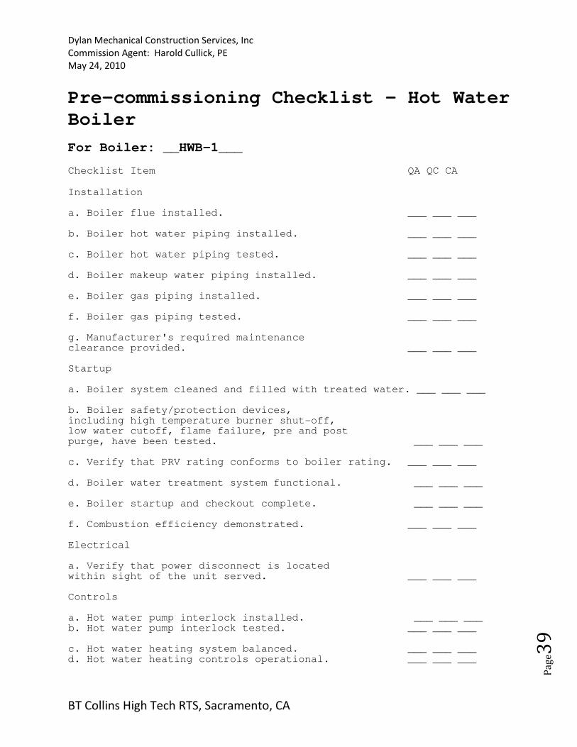
Pre-commissioning Checklist - Hot Water
Boiler
For Boiler: __HWB-1___
Checklist Item QA QC CA
Installation a. Boiler flue installed. ___ ___ ___ b. Boiler hot water piping installed. ___ ___ ___ c. Boiler hot water piping tested. ___ ___ ___ d. Boiler makeup water piping installed. ___ ___ ___ e. Boiler gas piping installed. ___ ___ ___ f. Boiler gas piping tested. ___ ___ ___ g. Manufacturer's required maintenance clearance provided. ___ ___ ___ Startup a. Boiler system cleaned and filled with treated water. ___ ___ ___ b. Boiler safety/protection devices, including high temperature burner shut-off, low water cutoff, flame failure, pre and post purge, have been tested. ___ ___ ___ c. Verify that PRV rating conforms to boiler rating. ___ ___ ___ d. Boiler water treatment system functional. ___ ___ ___ e. Boiler startup and checkout complete. ___ ___ ___ f. Combustion efficiency demonstrated. ___ ___ ___ Electrical a. Verify that power disconnect is located within sight of the unit served. ___ ___ ___ Controls a. Hot water pump interlock installed. ___ ___ ___ b. Hot water pump interlock tested. ___ ___ ___ c. Hot water heating system balanced. ___ ___ ___ d. Hot water heating controls operational. ___ ___ ___

Dylan Mechanical Construction Services, Inc
Commission Agent: Harold Cullick, PE
May 24, 2010
BT Collins High Tech RTS, Sacramento, CA
Pa
ge4
0

Dylan Mechanical Construction Services, Inc
Commission Agent: Harold Cullick, PE
May 24, 2010
BT Collins High Tech RTS, Sacramento, CA
Pa
ge4
1
Pre-commissioning Checklist – Demarc Room Vent Fan For Vent Fan: _____ Checklist Item QA QC CA
Installation
a. Ductwork connected properly. ___ ___ ___
b. Fan hung or supported properly and with vibration isolation. ___ ___ ___
Electrical
a. Power available to unit disconnect. ___ ___ ___
b. Proper motor rotation verified. ___ ___ ___
c. Verify that power disconnect is located
within sight of the unit it controls. ___ ___ ___
d. Power available to electric heating coil. ___ ___ ___
Controls
a. Control valves properly installed. ___ ___ ___
b. Control valves operable. ___ ___ ___
c. Verify proper location and installation of thermostat. ___ ___ ___
Testing, Adjusting, and Balancing (TAB)
a. TAB Report submitted. ___ ___ ___
Pre-commissioning Checklist - Exhaust Fan
Dylan Mechanical Construction Services, Inc
Commission Agent: Harold Cullick, PE
May 24, 2010
BT Collins High Tech RTS, Sacramento, CA
Pa
ge4
2
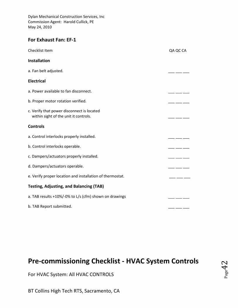
For Exhaust Fan: EF-1
Checklist Item QA QC CA
Installation
a. Fan belt adjusted. ___ ___ ___
Electrical
a. Power available to fan disconnect. ___ ___ ___
b. Proper motor rotation verified. ___ ___ ___
c. Verify that power disconnect is located
within sight of the unit it controls. ___ ___ ___
Controls
a. Control interlocks properly installed. ___ ___ ___
b. Control interlocks operable. ___ ___ ___
c. Dampers/actuators properly installed. ___ ___ ___
d. Dampers/actuators operable. ___ ___ ___
e. Verify proper location and installation of thermostat. ___ ___ ___
Testing, Adjusting, and Balancing (TAB)
a. TAB results +10%/-0% to L/s (cfm) shown on drawings ___ ___ ___
b. TAB Report submitted. ___ ___ ___
Pre-commissioning Checklist - HVAC System Controls
For HVAC System: All HVAC CONTROLS
Dylan Mechanical Construction Services, Inc
Commission Agent: Harold Cullick, PE
May 24, 2010
BT Collins High Tech RTS, Sacramento, CA
Pa
ge4
3
Checklist Item QA QC CA
Installation
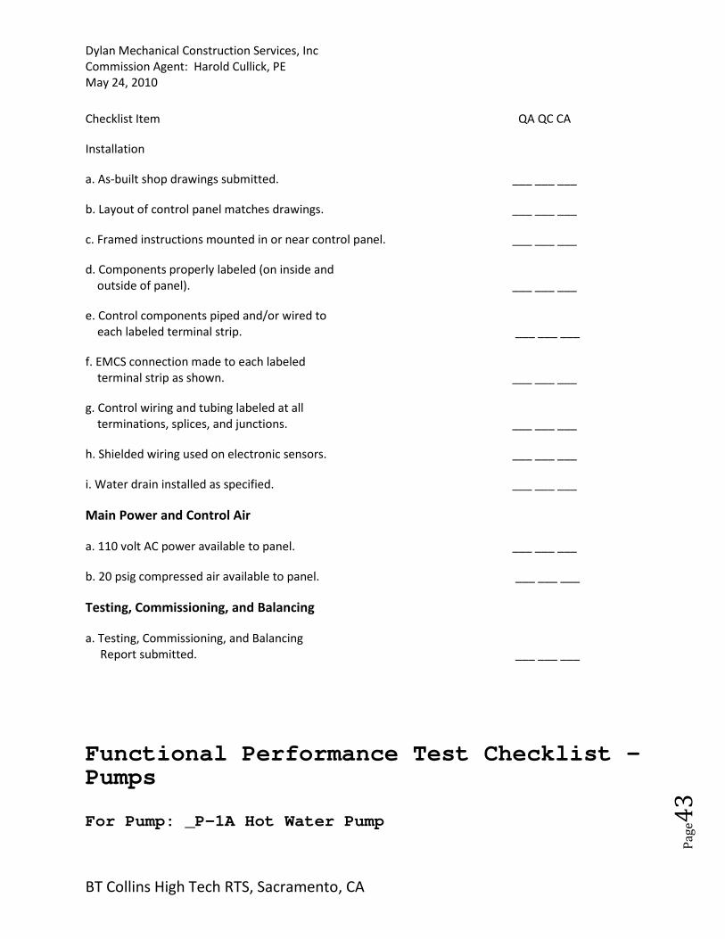
a. As-built shop drawings submitted. ___ ___ ___
b. Layout of control panel matches drawings. ___ ___ ___
c. Framed instructions mounted in or near control panel. ___ ___ ___
d. Components properly labeled (on inside and
outside of panel). ___ ___ ___
e. Control components piped and/or wired to
each labeled terminal strip. ___ ___ ___
f. EMCS connection made to each labeled
terminal strip as shown. ___ ___ ___
g. Control wiring and tubing labeled at all
terminations, splices, and junctions. ___ ___ ___
h. Shielded wiring used on electronic sensors. ___ ___ ___
i. Water drain installed as specified. ___ ___ ___
Main Power and Control Air
a. 110 volt AC power available to panel. ___ ___ ___
b. 20 psig compressed air available to panel. ___ ___ ___
Testing, Commissioning, and Balancing
a. Testing, Commissioning, and Balancing
Report submitted. ___ ___ ___
Functional Performance Test Checklist – Pumps For Pump: _P-1A Hot Water Pump
Dylan Mechanical Construction Services, Inc
Commission Agent: Harold Cullick, PE
May 24, 2010
BT Collins High Tech RTS, Sacramento, CA
Pa
ge4
4
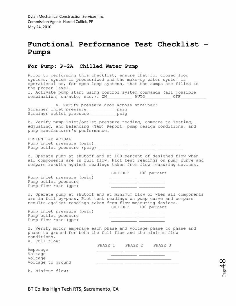
Prior to performing this checklist, ensure that for closed loop systems, system is pressurized and the make-up water system is operational or, for open loop systems, that the sumps are filled to the proper level. 1. Activate pump start using control system commands (all possible combination, on/auto, etc.). ON__________ AUTO__________ OFF__________
a. Verify pressure drop across strainer: Strainer inlet pressure __________ psig Strainer outlet pressure _________ psig b. Verify pump inlet/outlet pressure reading, compare to Testing, Adjusting, and Balancing (TAB) Report, pump design conditions, and pump manufacturer's performance. DESIGN TAB ACTUAL Pump inlet pressure (psig) ___________ __________ __________ Pump outlet pressure (psig) ___________ __________ __________ c. Operate pump at shutoff and at 100 percent of designed flow when all components are in full flow. Plot test readings on pump curve and compare results against readings taken from flow measuring devices.
SHUTOFF 100 percent Pump inlet pressure (psig) __________ __________ Pump outlet pressure __________ __________ Pump flow rate (gpm) __________ __________ d. Operate pump at shutoff and at minimum flow or when all components are in full by-pass. Plot test readings on pump curve and compare results against readings taken from flow measuring devices.
SHUTOFF 100 percent Pump inlet pressure (psig) __________ __________ Pump outlet pressure __________ __________ Pump flow rate (gpm) __________ __________ 2. Verify motor amperage each phase and voltage phase to phase and phase to ground for both the full flow and the minimum flow conditions. a. Full flow:
PHASE 1 PHASE 2 PHASE 3 Amperage __________ __________ __________ Voltage __________ __________ Voltage _________________________ Voltage to ground __________ __________ __________ b. Minimum flow:
PHASE 1 PHASE 2 PHASE 3
Amperage __________ __________ __________
Voltage __________ __________
Voltage _________________________
Dylan Mechanical Construction Services, Inc
Commission Agent: Harold Cullick, PE
May 24, 2010
BT Collins High Tech RTS, Sacramento, CA
Pa
ge4
5
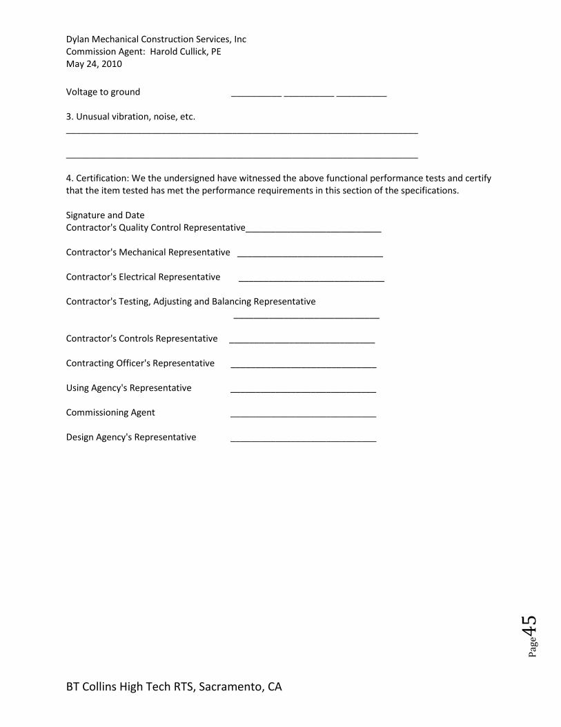
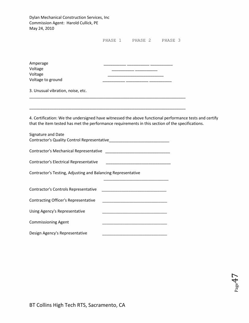
Voltage to ground __________ __________ __________
3. Unusual vibration, noise, etc.
______________________________________________________________________
______________________________________________________________________
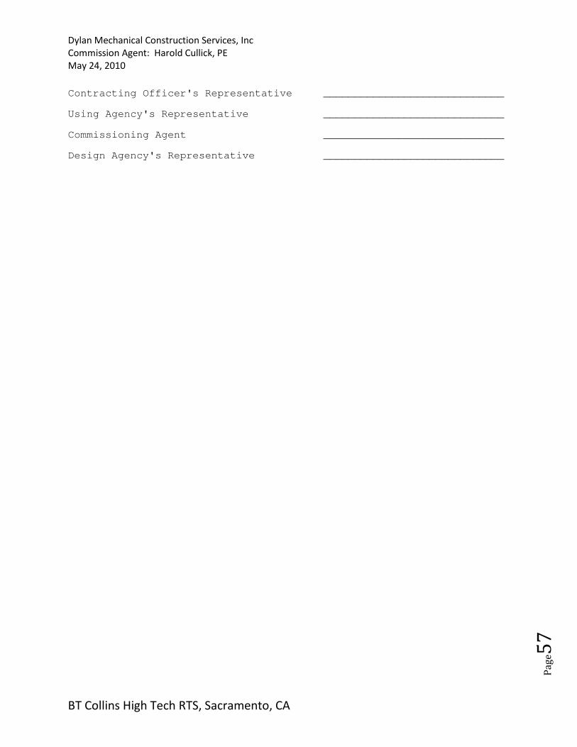
4. Certification: We the undersigned have witnessed the above functional performance tests and certify
that the item tested has met the performance requirements in this section of the specifications.
Signature and Date
Contractor's Quality Control Representative___________________________
Contractor's Mechanical Representative _____________________________
Contractor's Electrical Representative _____________________________
Contractor's Testing, Adjusting and Balancing Representative
_____________________________
Contractor's Controls Representative _____________________________
Contracting Officer's Representative _____________________________
Using Agency's Representative _____________________________
Commissioning Agent _____________________________
Design Agency's Representative _____________________________

Dylan Mechanical Construction Services, Inc
Commission Agent: Harold Cullick, PE
May 24, 2010
BT Collins High Tech RTS, Sacramento, CA
Pa
ge4
6
Functional Performance Test Checklist – Pumps For Pump: P-1B Hot Water Pump Prior to performing this checklist, ensure that for closed loop systems, system is pressurized and the make-up water system is operational or, for open loop systems, that the sumps are filled to the proper level. 1. Activate pump start using control system commands (all possible combination, on/auto, etc.). ON__________ AUTO__________ OFF__________
a. Verify pressure drop across strainer: Strainer inlet pressure __________ psig Strainer outlet pressure _________ psig b. Verify pump inlet/outlet pressure reading, compare to Testing, Adjusting, and Balancing (TAB) Report, pump design conditions, and pump manufacturer's performance. DESIGN TAB ACTUAL Pump inlet pressure (psig) ___________ __________ __________ Pump outlet pressure (psig) ___________ __________ __________ c. Operate pump at shutoff and at 100 percent of designed flow when all components are in full flow. Plot test readings on pump curve and compare results against readings taken from flow measuring devices.
SHUTOFF 100 percent Pump inlet pressure (psig) __________ __________ Pump outlet pressure __________ __________ Pump flow rate (gpm) __________ __________ d. Operate pump at shutoff and at minimum flow or when all components are in full by-pass. Plot test readings on pump curve and compare results against readings taken from flow measuring devices.
SHUTOFF 100 percent Pump inlet pressure (psig) __________ __________ Pump outlet pressure __________ __________ Pump flow rate (gpm) __________ __________ 2. Verify motor amperage each phase and voltage phase to phase and phase to ground for both the full flow and the minimum flow conditions. a. Full flow:
PHASE 1 PHASE 2 PHASE 3 Amperage __________ __________ __________ Voltage __________ __________ Voltage _________________________ Voltage to ground __________ __________ __________ b. Minimum flow:
Dylan Mechanical Construction Services, Inc
Commission Agent: Harold Cullick, PE
May 24, 2010
BT Collins High Tech RTS, Sacramento, CA
Pa
ge4
7
PHASE 1 PHASE 2 PHASE 3
Amperage __________ __________ __________
Voltage __________ __________
Voltage _________________________
Voltage to ground __________ __________ __________
3. Unusual vibration, noise, etc.
______________________________________________________________________
______________________________________________________________________
4. Certification: We the undersigned have witnessed the above functional performance tests and certify
that the item tested has met the performance requirements in this section of the specifications.
Signature and Date
Contractor's Quality Control Representative___________________________
Contractor's Mechanical Representative _____________________________
Contractor's Electrical Representative _____________________________
Contractor's Testing, Adjusting and Balancing Representative
_____________________________
Contractor's Controls Representative _____________________________
Contracting Officer's Representative _____________________________
Using Agency's Representative _____________________________
Commissioning Agent _____________________________
Design Agency's Representative _____________________________
Dylan Mechanical Construction Services, Inc
Commission Agent: Harold Cullick, PE
May 24, 2010
BT Collins High Tech RTS, Sacramento, CA
Pa
ge4
8
Functional Performance Test Checklist – Pumps For Pump: P-2A Chilled Water Pump Prior to performing this checklist, ensure that for closed loop systems, system is pressurized and the make-up water system is operational or, for open loop systems, that the sumps are filled to the proper level. 1. Activate pump start using control system commands (all possible combination, on/auto, etc.). ON__________ AUTO__________ OFF__________
a. Verify pressure drop across strainer: Strainer inlet pressure __________ psig Strainer outlet pressure _________ psig b. Verify pump inlet/outlet pressure reading, compare to Testing, Adjusting, and Balancing (TAB) Report, pump design conditions, and pump manufacturer's performance. DESIGN TAB ACTUAL Pump inlet pressure (psig) ___________ __________ __________ Pump outlet pressure (psig) ___________ __________ __________ c. Operate pump at shutoff and at 100 percent of designed flow when all components are in full flow. Plot test readings on pump curve and compare results against readings taken from flow measuring devices.
SHUTOFF 100 percent Pump inlet pressure (psig) __________ __________ Pump outlet pressure __________ __________ Pump flow rate (gpm) __________ __________ d. Operate pump at shutoff and at minimum flow or when all components are in full by-pass. Plot test readings on pump curve and compare results against readings taken from flow measuring devices.
SHUTOFF 100 percent Pump inlet pressure (psig) __________ __________ Pump outlet pressure __________ __________ Pump flow rate (gpm) __________ __________ 2. Verify motor amperage each phase and voltage phase to phase and phase to ground for both the full flow and the minimum flow conditions. a. Full flow:
PHASE 1 PHASE 2 PHASE 3 Amperage __________ __________ __________ Voltage __________ __________ Voltage _________________________ Voltage to ground __________ __________ __________ b. Minimum flow:
Dylan Mechanical Construction Services, Inc
Commission Agent: Harold Cullick, PE
May 24, 2010
BT Collins High Tech RTS, Sacramento, CA
Pa
ge4
9
PHASE 1 PHASE 2 PHASE 3
Amperage __________ __________ __________
Voltage __________ __________
Voltage _________________________
Voltage to ground __________ __________ __________
3. Unusual vibration, noise, etc.
______________________________________________________________________
______________________________________________________________________
4. Certification: We the undersigned have witnessed the above functional performance tests and certify
that the item tested has met the performance requirements in this section of the specifications.
Signature and Date
Contractor's Quality Control Representative___________________________
Contractor's Mechanical Representative _____________________________
Contractor's Electrical Representative _____________________________
Contractor's Testing, Adjusting and Balancing Representative
_____________________________
Contractor's Controls Representative _____________________________
Contracting Officer's Representative _____________________________
Using Agency's Representative _____________________________
Commissioning Agent _____________________________
Design Agency's Representative _____________________________
Functional Performance Test Checklist – Pumps For Pump: P-2B Chilled Water Pump Prior to performing this checklist, ensure that for closed loop systems, system is pressurized and the make-up water system is

Dylan Mechanical Construction Services, Inc
Commission Agent: Harold Cullick, PE
May 24, 2010
BT Collins High Tech RTS, Sacramento, CA
Pa
ge5
0
operational or, for open loop systems, that the sumps are filled to the proper level. 1. Activate pump start using control system commands (all possible combination, on/auto, etc.). ON__________ AUTO__________ OFF__________
a. Verify pressure drop across strainer: Strainer inlet pressure __________ psig Strainer outlet pressure _________ psig b. Verify pump inlet/outlet pressure reading, compare to Testing, Adjusting, and Balancing (TAB) Report, pump design conditions, and pump manufacturer's performance. DESIGN TAB ACTUAL Pump inlet pressure (psig) ___________ __________ __________ Pump outlet pressure (psig) ___________ __________ __________ c. Operate pump at shutoff and at 100 percent of designed flow when all components are in full flow. Plot test readings on pump curve and compare results against readings taken from flow measuring devices.
SHUTOFF 100 percent Pump inlet pressure (psig) __________ __________ Pump outlet pressure __________ __________ Pump flow rate (gpm) __________ __________ d. Operate pump at shutoff and at minimum flow or when all components are in full by-pass. Plot test readings on pump curve and compare results against readings taken from flow measuring devices.
SHUTOFF 100 percent Pump inlet pressure (psig) __________ __________ Pump outlet pressure __________ __________ Pump flow rate (gpm) __________ __________ 2. Verify motor amperage each phase and voltage phase to phase and phase to ground for both the full flow and the minimum flow conditions. a. Full flow:
PHASE 1 PHASE 2 PHASE 3 Amperage __________ __________ __________ Voltage __________ __________ Voltage _________________________ Voltage to ground __________ __________ __________ b. Minimum flow:
PHASE 1 PHASE 2 PHASE 3
Amperage __________ __________ __________
Voltage __________ __________
Voltage _________________________
Voltage to ground __________ __________ __________
Dylan Mechanical Construction Services, Inc
Commission Agent: Harold Cullick, PE
May 24, 2010
BT Collins High Tech RTS, Sacramento, CA
Pa
ge5
1
3. Unusual vibration, noise, etc.
______________________________________________________________________
______________________________________________________________________
4. Certification: We the undersigned have witnessed the above functional performance tests and certify
that the item tested has met the performance requirements in this section of the specifications.
Signature and Date
Contractor's Quality Control Representative___________________________
Contractor's Mechanical Representative _____________________________
Contractor's Electrical Representative _____________________________
Contractor's Testing, Adjusting and Balancing Representative
_____________________________
Contractor's Controls Representative _____________________________
Contracting Officer's Representative _____________________________
Using Agency's Representative _____________________________
Commissioning Agent _____________________________
Design Agency's Representative _____________________________
Dylan Mechanical Construction Services, Inc
Commission Agent: Harold Cullick, PE
May 24, 2010
BT Collins High Tech RTS, Sacramento, CA
Pa
ge5
2
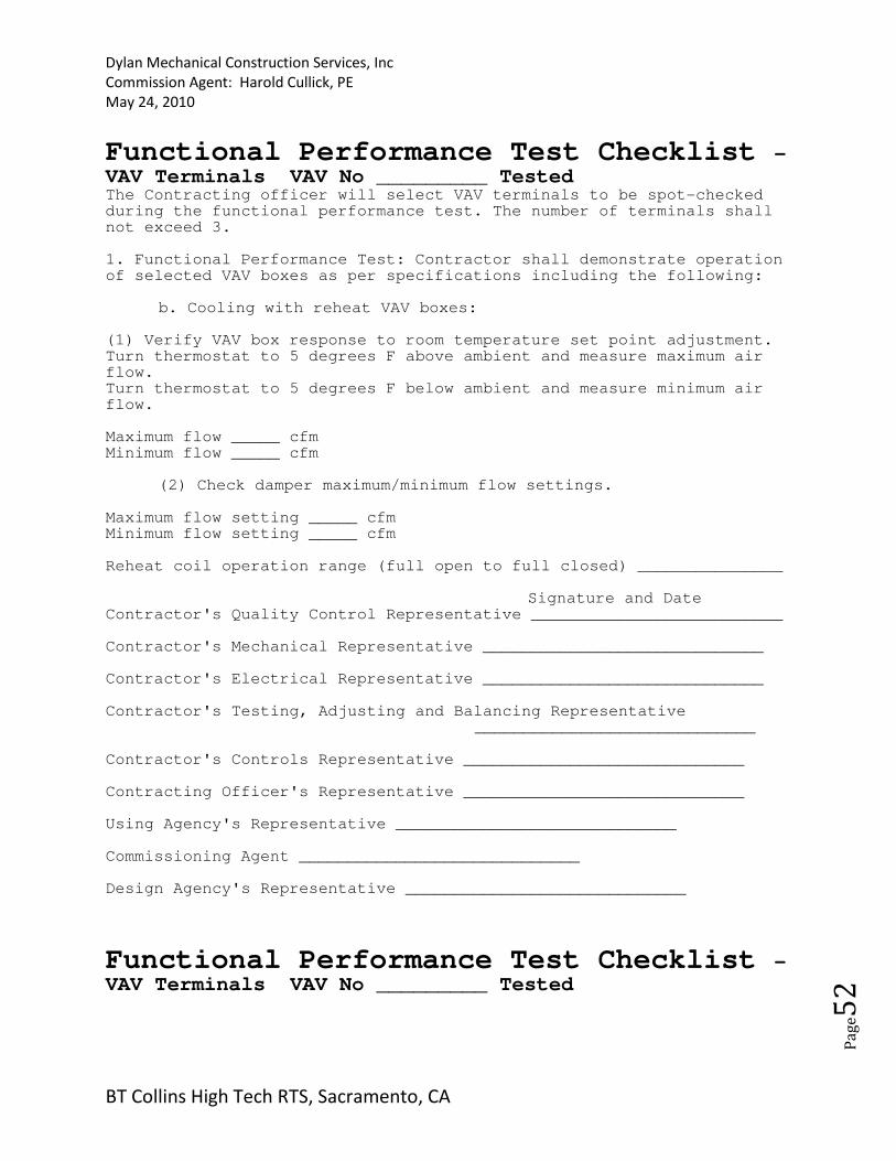
Functional Performance Test Checklist - VAV Terminals VAV No _________ Tested The Contracting officer will select VAV terminals to be spot-checked during the functional performance test. The number of terminals shall not exceed 3. 1. Functional Performance Test: Contractor shall demonstrate operation of selected VAV boxes as per specifications including the following:
b. Cooling with reheat VAV boxes: (1) Verify VAV box response to room temperature set point adjustment. Turn thermostat to 5 degrees F above ambient and measure maximum air flow. Turn thermostat to 5 degrees F below ambient and measure minimum air flow. Maximum flow _____ cfm Minimum flow _____ cfm
(2) Check damper maximum/minimum flow settings. Maximum flow setting _____ cfm Minimum flow setting _____ cfm Reheat coil operation range (full open to full closed) _______________
Signature and Date Contractor's Quality Control Representative __________________________ Contractor's Mechanical Representative _____________________________ Contractor's Electrical Representative _____________________________ Contractor's Testing, Adjusting and Balancing Representative
_____________________________ Contractor's Controls Representative _____________________________ Contracting Officer's Representative _____________________________ Using Agency's Representative _____________________________ Commissioning Agent _____________________________ Design Agency's Representative _____________________________
Functional Performance Test Checklist - VAV Terminals VAV No _________ Tested
Dylan Mechanical Construction Services, Inc
Commission Agent: Harold Cullick, PE
May 24, 2010
BT Collins High Tech RTS, Sacramento, CA
Pa
ge5
3
The Contracting officer will select VAV terminals to be spot-checked during the functional performance test. The number of terminals shall not exceed 3. 1. Functional Performance Test: Contractor shall demonstrate operation of selected VAV boxes as per specifications including the following:
b. Cooling with reheat VAV boxes: (1) Verify VAV box response to room temperature set point adjustment. Turn thermostat to 5 degrees F above ambient and measure maximum air flow. Turn thermostat to 5 degrees F below ambient and measure minimum air flow. Maximum flow _____ cfm Minimum flow _____ cfm
(2) Check damper maximum/minimum flow settings. Maximum flow setting _____ cfm Minimum flow setting _____ cfm Reheat coil operation range (full open to full closed) _______________
Signature and Date Contractor's Quality Control Representative __________________________ Contractor's Mechanical Representative _____________________________ Contractor's Electrical Representative _____________________________ Contractor's Testing, Adjusting and Balancing Representative
_____________________________ Contractor's Controls Representative _____________________________ Contracting Officer's Representative _____________________________ Using Agency's Representative _____________________________ Commissioning Agent _____________________________ Design Agency's Representative _____________________________
Functional Performance Test Checklist - VAV Terminals VAV No _________ Tested The Contracting officer will select VAV terminals to be spot-checked during the functional performance test. The number of terminals shall not exceed 3. 1. Functional Performance Test: Contractor shall demonstrate operation of selected VAV boxes as per specifications including the following:
Dylan Mechanical Construction Services, Inc
Commission Agent: Harold Cullick, PE
May 24, 2010
BT Collins High Tech RTS, Sacramento, CA
Pa
ge5
4
b. Cooling with reheat VAV boxes: (1) Verify VAV box response to room temperature set point adjustment. Turn thermostat to 5 degrees F above ambient and measure maximum air flow. Turn thermostat to 5 degrees F below ambient and measure minimum air flow. Maximum flow _____ cfm Minimum flow _____ cfm
(2) Check damper maximum/minimum flow settings. Maximum flow setting _____ cfm Minimum flow setting _____ cfm Reheat coil operation range (full open to full closed) _______________
Signature and Date Contractor's Quality Control Representative __________________________ Contractor's Mechanical Representative _____________________________ Contractor's Electrical Representative _____________________________ Contractor's Testing, Adjusting and Balancing Representative
_____________________________ Contractor's Controls Representative _____________________________ Contracting Officer's Representative _____________________________ Using Agency's Representative _____________________________ Commissioning Agent _____________________________ Design Agency's Representative _____________________________
Dylan Mechanical Construction Services, Inc
Commission Agent: Harold Cullick, PE
May 24, 2010
BT Collins High Tech RTS, Sacramento, CA
Pa
ge5
5
Functional Performance Test Checklist -
Variable Volume Air Handling Unit
For Air Handling Unit: AHU#1 Ensure that a slight negative pressure exists on inboard side of the outside air dampers throughout the operation of the dampers. Modulate OA,RA, and EA dampers from fully open to fully closed positions. 1. Functional Performance Test: Contractor shall verify operation of air handling unit as per specification including the following:
a. The following shall be verified when the supply and return fans operating mode is initiated: (1) All dampers in normal position and fan inlet vanes modulate to maintain the required static pressure.________________________ (2) All valves in normal position. ______________________________ (3) System safeties allow start if safety conditions are met. _____ (4) VAV fan controller shall "soft-start" fan. __________________ (5) Modulate all VAV boxes to minimum air flow and verify that the static pressure does not exceed the design static pressure Class shown. ______________________________________________________________________ b. Occupied mode of operation - economizer de-energized. (1) Outside air damper at minimum position. _____________________ (2) Return air damper open. _____________________________________ (3) Relief air damper at minimum position. ______________________ (4) Chilled water control valve modulating to maintain leaving air temperature set point. ___________________________________________ (5) Fan VAV controller receiving signal from duct static pressure sensor and modulating fan to maintain supply duct static pressure set point. _________________________________________________________________ c. Occupied mode of operation - economizer energized. (1) Outside air damper modulated to maintain mixed air temperature set point. _______________________________________________________ (2) Relief air damper modulates with outside air damper according to sequence of operation. __________________________________________________ (3) Chilled water control valve modulating to maintain leaving air
Dylan Mechanical Construction Services, Inc
Commission Agent: Harold Cullick, PE
May 24, 2010
BT Collins High Tech RTS, Sacramento, CA
Pa
ge5
6
temperature set point. _____________________________________________________ (4) Hot water control valve modulating to maintain leaving air temperature set point. _____________________________________________________ (5) Fan VAV controller receiving signal from duct static pressure sensor and modulating fan to maintain supply duct static pressure set point. _____________________________________________________________ d. Unoccupied mode of operation
(1) All dampers in normal position. _____________________________ (2) Verify low limit space temperature is maintained as specified in sequence of operation. _____________________________
e. The following shall be verified when the supply and exhaust fans off mode is initiated: (1) All dampers in normal position. _____________________________ (2) All valves in normal position. ______________________________ (3) Fan de-energizes. ___________________________________________ f. Verify the chilled water coil control valve operation by setting all VAV's to maximum and minimum cooling.
Max cooling Min cooling Supply air volume _____ cfm) __________ ___________ Supply air temp. (_____ degrees F) __________ ___________ g. Verify safety shut down initiated by smoke detectors. ____________ h. Verify safety shut down initiated by low temperature protection thermostat. ____________________________________________________ 2. Certification: We the undersigned have witnessed the above functional performance tests and certify that the item tested has met the performance requirements in this section of the specifications.
Signature and Date Contractor's Quality Control Representative ___________________________ Contractor's Mechanical Representative _____________________________ Contractor's Electrical Representative _____________________________ Contractor's Testing, Adjusting and Balancing Representative _____________________________ Contractor's Controls Representative _____________________________
Dylan Mechanical Construction Services, Inc
Commission Agent: Harold Cullick, PE
May 24, 2010
BT Collins High Tech RTS, Sacramento, CA
Pa
ge5
7
Contracting Officer's Representative _____________________________ Using Agency's Representative _____________________________ Commissioning Agent _____________________________ Design Agency's Representative _____________________________
Dylan Mechanical Construction Services, Inc
Commission Agent: Harold Cullick, PE
May 24, 2010
BT Collins High Tech RTS, Sacramento, CA
Pa
ge5
8
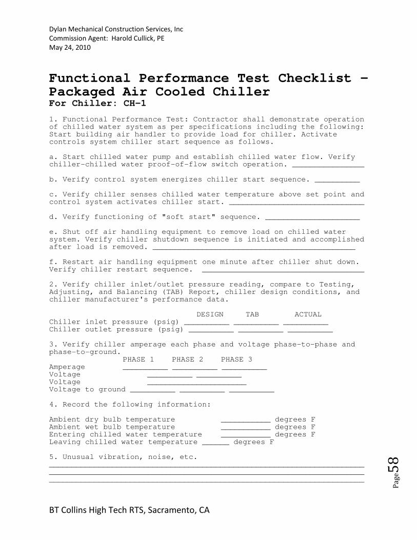
Functional Performance Test Checklist - Packaged Air Cooled Chiller For Chiller: CH-1 1. Functional Performance Test: Contractor shall demonstrate operation of chilled water system as per specifications including the following: Start building air handler to provide load for chiller. Activate controls system chiller start sequence as follows. a. Start chilled water pump and establish chilled water flow. Verify chiller-chilled water proof-of-flow switch operation. ________________ b. Verify control system energizes chiller start sequence. __________ c. Verify chiller senses chilled water temperature above set point and control system activates chiller start. ______________________________ d. Verify functioning of "soft start" sequence. _____________________ e. Shut off air handling equipment to remove load on chilled water system. Verify chiller shutdown sequence is initiated and accomplished after load is removed. _____________________________________________ f. Restart air handling equipment one minute after chiller shut down. Verify chiller restart sequence. ____________________________________ 2. Verify chiller inlet/outlet pressure reading, compare to Testing, Adjusting, and Balancing (TAB) Report, chiller design conditions, and chiller manufacturer's performance data.
DESIGN TAB ACTUAL Chiller inlet pressure (psig) __________ __________ __________ Chiller outlet pressure (psig) __________ __________ __________ 3. Verify chiller amperage each phase and voltage phase-to-phase and phase-to-ground.
PHASE 1 PHASE 2 PHASE 3 Amperage __________ __________ __________ Voltage __________ __________ Voltage ______________________ Voltage to ground __________ __________ __________ 4. Record the following information: Ambient dry bulb temperature ___________ degrees F Ambient wet bulb temperature ___________ degrees F Entering chilled water temperature ___________ degrees F Leaving chilled water temperature ______ degrees F 5. Unusual vibration, noise, etc. __________________________________________________________________________________________________________________________________________________________________________________________________________________
Dylan Mechanical Construction Services, Inc
Commission Agent: Harold Cullick, PE
May 24, 2010
BT Collins High Tech RTS, Sacramento, CA
Pa
ge5
9
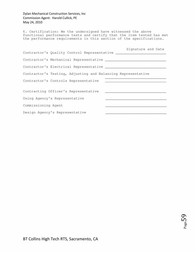
6. Certification: We the undersigned have witnessed the above functional performance tests and certify that the item tested has met the performance requirements in this section of the specifications.
Signature and Date Contractor's Quality Control Representative ________________________ Contractor's Mechanical Representative _____________________________ Contractor's Electrical Representative _____________________________ Contractor's Testing, Adjusting and Balancing Representative _____________________________ Contractor's Controls Representative _____________________________ Contracting Officer's Representative _____________________________ Using Agency's Representative _____________________________ Commissioning Agent _____________________________ Design Agency's Representative _____________________________
Dylan Mechanical Construction Services, Inc
Commission Agent: Harold Cullick, PE
May 24, 2010
BT Collins High Tech RTS, Sacramento, CA
Pa
ge6
0
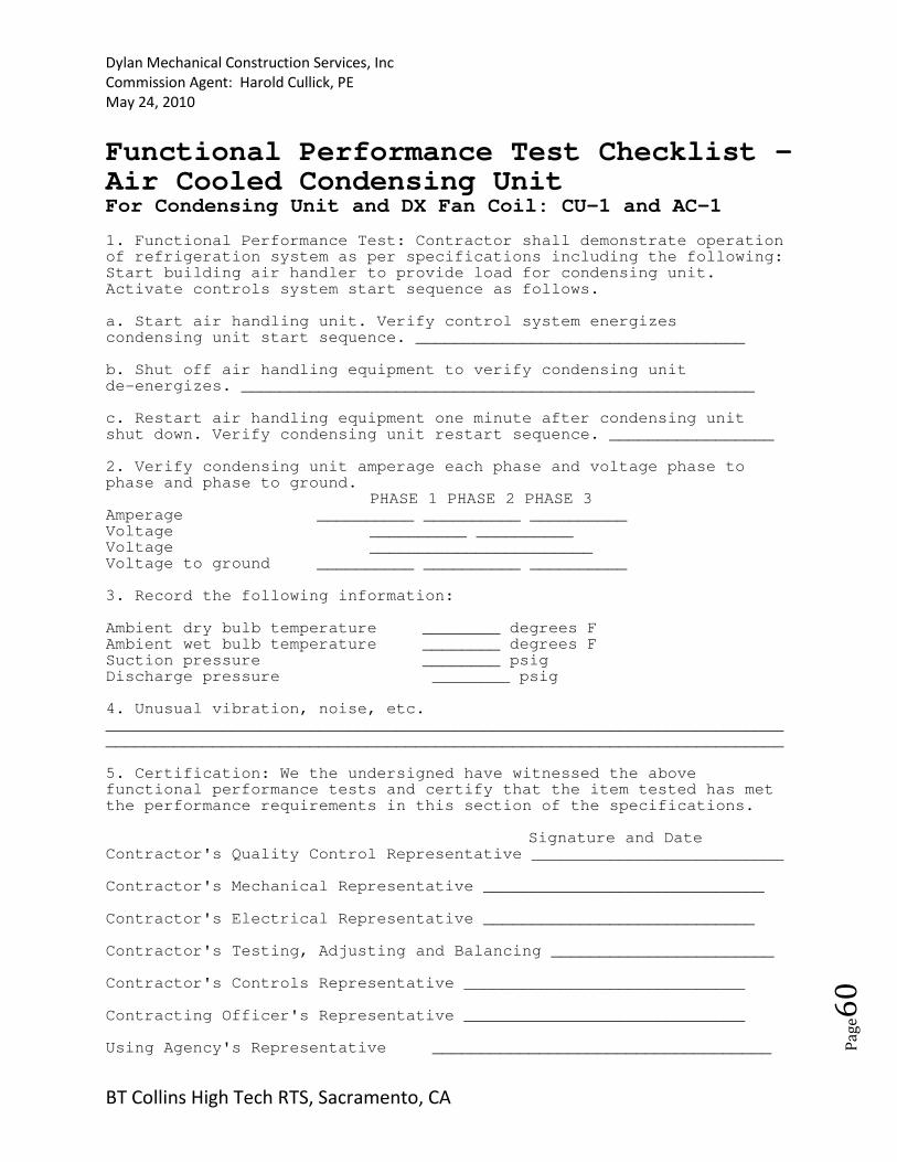
Functional Performance Test Checklist - Air Cooled Condensing Unit For Condensing Unit and DX Fan Coil: CU-1 and AC-1 1. Functional Performance Test: Contractor shall demonstrate operation of refrigeration system as per specifications including the following: Start building air handler to provide load for condensing unit. Activate controls system start sequence as follows. a. Start air handling unit. Verify control system energizes condensing unit start sequence. __________________________________ b. Shut off air handling equipment to verify condensing unit de-energizes. _____________________________________________________ c. Restart air handling equipment one minute after condensing unit shut down. Verify condensing unit restart sequence. _________________ 2. Verify condensing unit amperage each phase and voltage phase to phase and phase to ground.
PHASE 1 PHASE 2 PHASE 3 Amperage __________ __________ __________ Voltage __________ __________ Voltage _______________________ Voltage to ground __________ __________ __________ 3. Record the following information: Ambient dry bulb temperature ________ degrees F Ambient wet bulb temperature ________ degrees F Suction pressure ________ psig Discharge pressure ________ psig 4. Unusual vibration, noise, etc. ______________________________________________________________________ ______________________________________________________________________ 5. Certification: We the undersigned have witnessed the above functional performance tests and certify that the item tested has met the performance requirements in this section of the specifications.
Signature and Date Contractor's Quality Control Representative __________________________ Contractor's Mechanical Representative _____________________________ Contractor's Electrical Representative ____________________________ Contractor's Testing, Adjusting and Balancing _______________________ Contractor's Controls Representative _____________________________ Contracting Officer's Representative _____________________________ Using Agency's Representative ___________________________________
Dylan Mechanical Construction Services, Inc
Commission Agent: Harold Cullick, PE
May 24, 2010
BT Collins High Tech RTS, Sacramento, CA
Pa
ge6
1
Commissioning Agent _____________________________ Design Agency's Representative _____________________________

Dylan Mechanical Construction Services, Inc
Commission Agent: Harold Cullick, PE
May 24, 2010
BT Collins High Tech RTS, Sacramento, CA
Pa
ge6
2
Functional Performance Test Checklist - Hot Water Boiler For Boiler: HWB-1 1. Functional Performance Test: Contractor shall demonstrate operation of hot water system as per specifications including the following: Start building heating equipment to provide load for boiler. Activate controls system boiler start sequence as follows. a. Start hot water pump and establish hot water flow. Verify boiler hot water proof-of-flow switch operation. ___________________________ b. Verify control system energizes boiler start sequence. ___________ c. Verify boiler senses hot water temperature below set point and control system activates boiler start. ______________________________ d. Shut off building heating equipment to remove load on hot water system. Verify boiler shutdown sequence is initiated and accomplished after load is removed. ______________________________________________ 2. Verify boiler inlet/outlet pressure reading, compare to Test and Balance (TAB) Report, boiler design conditions, and boiler manufacturer's performance data. DESIGN TAB ACTUAL Boiler inlet pressure (psig) __________ _________ __________ Boiler outlet pressure (psig) __________ _________ __________ Boiler flow rate (gpm) __________ _________ __________ Flue-gas temperature at boiler outlet _________ __________ Percent carbon dioxide in flue-gas _________ __________ Draft at boiler flue-gas exit _________ __________ Draft or pressure in furnace _________ __________ Stack emission pollutants __________ _________ __________ Concentration Fuel type __________ _________ __________ Combustion efficiency __________ _________ __________ 3. Record the following information: Ambient temperature __________ degrees F Entering hot water temperature __________ degrees F Leaving hot water temperature __________ degrees F 4. Verify temperatures in item 3 are in accordance with the reset schedule. ________________________________________________________ 5. Verify proper operation of boiler safeties. _____________________ 6. Unusual vibration, noise, etc. __________________________________________________________________ ______________________________________________________________________ 7. Visually check refractory for cracks or spalling and refractory and
Dylan Mechanical Construction Services, Inc
Commission Agent: Harold Cullick, PE
May 24, 2010
BT Collins High Tech RTS, Sacramento, CA
Pa
ge6
3
tubes for flame impingement. ________________________________________ 8. Certification: We the undersigned have witnessed the above functional performance tests and certify that the item tested has met the performance requirements in this section of the specifications.
Signature and Date Contractor's Quality Control Representative _________________________ Contractor's Mechanical Representative ____________________________ Contractor's Electrical Representative ____________________________ Contractor's Testing, Adjusting and Balancing Representative
___________________________ Contractor's Controls Representative _____________________________ Contracting Officer's Representative _____________________________ Using Agency's Representative _____________________________ Commissioning Agent _____________________________ Design Agency's Representative _____________________________
Dylan Mechanical Construction Services, Inc
Commission Agent: Harold Cullick, PE
May 24, 2010
BT Collins High Tech RTS, Sacramento, CA
Pa
ge6
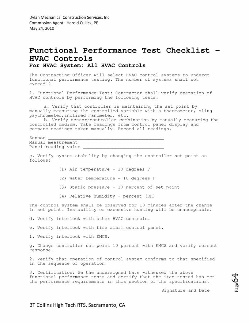
4
Functional Performance Test Checklist - HVAC Controls For HVAC System: All HVAC Controls The Contracting Officer will select HVAC control systems to undergo functional performance testing. The number of systems shall not exceed 2. 1. Functional Performance Test: Contractor shall verify operation of HVAC controls by performing the following tests:
a. Verify that controller is maintaining the set point by manually measuring the controlled variable with a thermometer, sling psychrometer,inclined manometer, etc.
b. Verify sensor/controller combination by manually measuring the controlled medium. Take readings from control panel display and compare readings taken manually. Record all readings. Sensor ___________________________________________ Manual measurement _______________________________ Panel reading value ______________________________ c. Verify system stability by changing the controller set point as follows:
(1) Air temperature - 10 degrees F (2) Water temperature - 10 degrees F (3) Static pressure - 10 percent of set point (4) Relative humidity - percent (RH)
The control system shall be observed for 10 minutes after the change in set point. Instability or excessive hunting will be unacceptable. d. Verify interlock with other HVAC controls. e. Verify interlock with fire alarm control panel. f. Verify interlock with EMCS. g. Change controller set point 10 percent with EMCS and verify correct response. 2. Verify that operation of control system conforms to that specified in the sequence of operation. 3. Certification: We the undersigned have witnessed the above functional performance tests and certify that the item tested has met the performance requirements in this section of the specifications.
Signature and Date
Dylan Mechanical Construction Services, Inc
Commission Agent: Harold Cullick, PE
May 24, 2010
BT Collins High Tech RTS, Sacramento, CA
Pa
ge6
5
Contractor's Quality Control Representative _________________________ Contractor's Mechanical Representative _____________________________ Contractor's Electrical Representative _____________________________ Contractor's Testing, Adjusting and Balancing Representative _____________________________ Contractor's Controls Representative _____________________________ Contractor's Officer's Representative _____________________________ Using Agency's Representative _______________________________ Commissioning Agent _____________________________ Design Agency's Representative _____________________________