875-0125-002 csi programming manual 050706programming manual iii csi wireless inc. limited warranty...
TRANSCRIPT

Programming Manual
Part Number: 875-0125-002 Date: June 2005

Programming Manual ii
Copyright Notice
Copyright 2005 by CSI Wireless Inc. All rights reserved.
No part of this manual may be stored in a retrieval system, transmitted, or reproduced by any means, including, but not limited to photocopy, photograph, digitizing, or otherwise, without the prior written permission from CSI Wireless Inc.
CSI Wireless Inc. 4110 – 9th Street SE Calgary, Alberta, Canada T2G 3C4
Telephone number: +1-403-259-3311 Fax number: +1-403-259-8866 E-mail address: [email protected] Web Site: www.csi-wireless.com
Programming Manual iii
CSI Wireless Inc. Limited Warranty
CSI Wireless Inc. (hereinafter referred to as "CSI Wireless") products are warranted, subject to the conditions set forth herein below, against defects in material and workmanship for a period of 12 months. Warranty services will be provided through your CSI Wireless distribution center, please contact them for shipping information. You must retain your proof of purchase for warranty purposes.
Limitation of Liability
The Limited Warranty contained herein replaces all other warranties, express or implied, including warranties of merchantability or fitness for a particular purpose. CSI Wireless hereby disclaims and excludes all other warranties. In no event shall CSI Wireless be liable for direct, indirect, incidental, collateral or consequential damages of any kind, including but not limited to damages resulting from installation or use, quality, performance, or accuracy of CSI Wireless products. This warranty provides you with your exclusive remedies for any breach in warranty.
Purchaser’s Exclusive Remedy
The purchaser’s exclusive remedy under this warranty shall be limited to the repair or replacement, at the option of CSI Wireless, of any defective part(s) of CSI Wireless receivers or accessories. Repairs shall be made through a CSI Wireless approved service center only. Unauthorized repairs to CSI Wireless products shall render this warranty null and void.

Programming Manual iv
Governing Legislation
This warranty shall be governed by the laws of the Province of Alberta, Canada. This warranty gives you specific legal rights which may vary with Province/State and Country, and accordingly, some limitations may not apply to you.
Conditions
CSI Wireless does not warrant damage due to misuse, abuse, improper installation, neglect, lightning (or other electrical discharge) or fresh/salt water immersion of CSI Wireless products. Repair, modification or service of CSI Wireless products by unauthorized person(s) or party(s) shall render this warranty null and void. CSI Wireless does not warrant or guarantee the precision or accuracy of positions obtained when using CSI Wireless products. Product accuracy as stated in CSI Wireless literature and/or product specifications serves to provide only an estimate of achievable accuracy based on:
• Specifications provided by the US Department of Defense (US DoD) for GPS Positioning,
• GPS OEM Receiver specifications of the appropriate manufacturer (if applicable),
• DGPS service provider performance specifications
CSI Wireless reserves the right to modify CSI Wireless products without any obligation to notify, supply or install any improvements or alterations to existing products.

Programming Manual v
Table of Contents List of Figures ..................................................................................................................................xi List of Tables....................................................................................................................................xi Preface xiii
Organization ........................................................................................................................xiii Customer Service................................................................................................................xv World Wide Web Site......................................................................................................xvi Document Conventions ...................................................................................................xvi Notes, Cautions, and Warnings......................................................................................xvi
1. Introduction............................................................................................................................1 1.1 Summary of Protocols...............................................................................................1
1.1.1 NMEA 0183...................................................................................................1 1.1.2 Binary ..............................................................................................................3 1.1.3 RTCM..............................................................................................................4
1.2 Communications.........................................................................................................5 1.2.1 Terminal Programs ......................................................................................5 1.2.2 PocketMAX and PocketMAX PC ............................................................6
2. Data Messages ........................................................................................................................8 2.1 GGA Data Message....................................................................................................8 2.2 GLL Data Message......................................................................................................9 2.3 GSA Data Message .................................................................................................. 10 2.4 GST Data Message .................................................................................................. 11 2.5 GSV Data Message .................................................................................................. 11 2.6 RMC Data Message ................................................................................................. 12
Programming Manual vi
2.7 RRE Data Message................................................................................................... 13 2.8 VTG Data Message.................................................................................................. 13 2.9 ZDA Data Message ................................................................................................. 14 2.10 RD1 Data Message .................................................................................................. 15 2.11 $PCSI,1 Beacon Status Message........................................................................... 15 2.12 HDT Data Message ................................................................................................. 16 2.13 ROT Data Message ................................................................................................. 16 2.14 HPR Data Message .................................................................................................. 17 2.15 $PSAT,GBS Data Message..................................................................................... 17
3. General Commands........................................................................................................... 19 3.1 $JASC,D1................................................................................................................... 21 3.2 $JAIR ........................................................................................................................... 21 3.3 $JASC,VIRTUAL ...................................................................................................... 22 3.4 $JALT.......................................................................................................................... 23 3.5 $JLIMIT ....................................................................................................................... 24 3.6 $JAPP .......................................................................................................................... 24 3.7 $JBAUD...................................................................................................................... 25 3.8 $JCONN.................................................................................................................... 26 3.9 $JDIFF ......................................................................................................................... 27 3.10 $JK 27 3.11 $JPOS.......................................................................................................................... 28 3.12 $JQUERY,GUIDE .................................................................................................... 29 3.13 $JRESET...................................................................................................................... 29 3.14 $JSAVE........................................................................................................................ 29 3.15 $JSHOW.................................................................................................................... 30 3.16 $JT 32 3.17 $JI 33

Programming Manual vii
3.18 $JBIN........................................................................................................................... 34 4. GPS Commands .................................................................................................................. 35
4.1 $JASC.......................................................................................................................... 35 4.2 $JPOS,M ..................................................................................................................... 37 4.3 $JAGE ......................................................................................................................... 37 4.4 $JOFF.......................................................................................................................... 38 4.5 $JMASK ...................................................................................................................... 38 4.6 $JNP............................................................................................................................ 39
This command allows the user to specify the number of decimal places output in the GGA and GLL messages. ................................................................ 39
This command has the following definition......................................................... 39
$JNP,x<CR><LF>........................................................................................................... 39
Where 'x' specifies the number of decimal places from 1 to 5. This command will affect both the GGA and the GLL messages. ....................... 39 4.7 $J4STRING................................................................................................................ 39 4.8 $JRAIM ....................................................................................................................... 40 4.9 $JSMOOTH............................................................................................................... 41
5. WAAS Commands............................................................................................................. 43 5.1 $JWAASPRN ............................................................................................................ 43 5.2 $JGEO......................................................................................................................... 44 5.3 $JASC,RTCM............................................................................................................ 45
6. OmniSTAR Commands (for DGPS MAX only).......................................................... 47 6.1 $JLBEAM .................................................................................................................... 47 6.2 $JLXBEAM................................................................................................................. 49 6.3 $JOMS......................................................................................................................... 50 6.4 $JOMR........................................................................................................................ 51 6.5 $JFREQ....................................................................................................................... 52

Programming Manual viii
6.6 $JGEO......................................................................................................................... 53 7. Beacon Commands (for all receivers excluding Vector and Vector Sensor)...... 55
7.1 RTCM Output ($JASC,BEAC,r)........................................................................... 56 7.2 Tune Command ($GPMSK) .................................................................................. 56
7.2.1 Full Manual Tune Command ($GPMSK) ............................................. 56 7.3 $PCSI,0 ....................................................................................................................... 58 7.4 Status Line A, Channel 0 ($PCSI,1)..................................................................... 59 7.5 Status Line B, Channel 1 ($PCSI,2) ..................................................................... 60 7.6 Search Dump ($PCSI,3) ......................................................................................... 61 7.7 $PCSI,4 ....................................................................................................................... 63 7.8 $GPCRQ.................................................................................................................... 63
7.8.1 Operating Status Query ($GPCRQ).................................................... 63 7.8.2 Performance Status Query ($GPCRQ)............................................... 64
7.9 $CRMSS ..................................................................................................................... 64 7.10 $CRMSK .................................................................................................................... 65
8. Heading Commands (for Vector products only)........................................................ 66 8.1 $JATT,TILTAID........................................................................................................ 67 8.2 $JATT,TILTCAL....................................................................................................... 68 8.3 $JATT,MAGAID....................................................................................................... 68 8.4 $JATT,MAGCLR and MAGCAL .......................................................................... 69 8.5 $JATT,GYROAID.................................................................................................... 70 8.6 $JATT,LEVEL ............................................................................................................ 71 8.7 $JATT,CSEP .............................................................................................................. 71 8.8 $JATT,MSEP (for Vector Sensor/Sensor PRO and OEM only).................... 72 8.9 $JATT,HTAU............................................................................................................ 72 8.10 $JATT,PTAU............................................................................................................. 73 8.11 $JATT,HRTAU ......................................................................................................... 74
Programming Manual ix
8.12 $JATT,COGTAU..................................................................................................... 75 8.13 $JATT,SPDTAU ....................................................................................................... 76 8.14 $JATT,HBIAS ............................................................................................................ 77 8.15 $JATT,PBIAS ............................................................................................................. 78 8.16 $JATT,NEGTILT ...................................................................................................... 78 8.17 $JATT,ROLL ............................................................................................................. 79 8.18 $JATT,SEARCH ....................................................................................................... 79 8.19 $JATT,FLIPBRD........................................................................................................ 80 8.20 $JATT,SUMMARY ................................................................................................... 80 8.21 $JATT,HELP .............................................................................................................. 82
9. e-Dif Commands (for Mini MAX, PowerMAX and DGPS MAX only) ................. 84 9.1 $JRAD,1 ..................................................................................................................... 84 9.2 $JRAD,1,P .................................................................................................................. 85 9.3 $JRAD,1,lat,lon,height............................................................................................. 85 9.4 $JRAD,2 ..................................................................................................................... 86 9.5 $JRAD,3 ..................................................................................................................... 86
10. Binary Data ...................................................................................................................... 88 10.1 Binary Message Structure ...................................................................................... 88 10.2 Bin 1 ............................................................................................................................ 89 10.3 Bin 2 ............................................................................................................................ 90 10.4 Bin 80.......................................................................................................................... 91 10.5 Bin 93.......................................................................................................................... 92 10.6 Bin 94.......................................................................................................................... 93 10.7 Bin 95.......................................................................................................................... 94 10.8 Bin 96.......................................................................................................................... 95 10.9 Bin 97.......................................................................................................................... 96 10.10 Bin 98.......................................................................................................................... 96

Programming Manual x
10.11 Bin 99.......................................................................................................................... 98 11. Menu System Commands (for DGPS MAX only)................................................101
11.1 Virtual Circuit ($JCONN,AB) ............................................................................102 11.2 $PCSI,HELP.............................................................................................................102 11.3 $PCSI,BAUD...........................................................................................................102 11.4 $PCSI,STATUS .......................................................................................................103 11.5 $PCSI,SETUP,SET ..................................................................................................103 11.6 $PCSI,SETUP,SHOW ...........................................................................................104 11.7 $PCSI,SETUP,SAVE ...............................................................................................105 11.8 $PCSI,SETUP,READ..............................................................................................106 11.9 $PCSI,SETUP,RESET .............................................................................................106 11.10 $PCSI,SETUP,INTRO ...........................................................................................107 11.11 $PCSI,SETUP,MUX, ..............................................................................................107
12. Configuration Wizard (for DGPS MAX only) ......................................................108 12.1 Virtual Circuit ($JCONN,AB) ............................................................................109 12.2 $PCSI,WIZARD,SET.............................................................................................109 12.3 $PCSI,WIZARD,RATES.......................................................................................110 12.4 $PCSI,WIZARD,SHOW......................................................................................111
13. Frequently Asked Questions ....................................................................................112
Appendix A - Resources...........................................................................................................115 Further Reading ..........................................................................................................................116 Index ..........................................................................................................................................117

Programming Manual xi
List of Tables
Table 1-1 NMEA Message Elements...........................................................................................2 Table 1-2 Binary Message Structure...........................................................................................4 Table 2-1 GPS NMEA Messages ..................................................................................................8 Table 2-2 GGA Data Message Defined......................................................................................9 Table 2-3 GLL Data Message Defined..................................................................................... 10 Table 2-4 GSA Data Message Defined.................................................................................... 10 Table 2-5 GST Data Message Defined .................................................................................... 11 Table 2-6 GSV Data Message Defined .................................................................................... 12 Table 2-7 RMC Data Message Defined................................................................................... 12 Table 2-8 RRE Data Message Defined..................................................................................... 13 Table 2-9 VTG Data Message Defined.................................................................................... 14 Table 2-10 ZDA Data Message Defined................................................................................. 14 Table 2-11 RD1 Data Message Defined.................................................................................. 15 Table 2-12 $PCSI,1 Beacon Status Message Defined .......................................................... 16 Table 2-13 HPR Data Message Defined.................................................................................. 17 Table 2-14 $PSAT,GBS Data Message Defined .................................................................... 18 Table 3-1 General Commands.................................................................................................. 20 Table 4-1 GPS Commands ......................................................................................................... 35 Table 5-1 WAAS Commands.................................................................................................... 43 Table 6-1 OmniSTAR Commands............................................................................................ 47 Table 7-1 Beacon Commands ................................................................................................... 55 Table 8-1 GPS Heading Commands......................................................................................... 67 Table 9-1 e-Dif Commands........................................................................................................ 84 Table 10-1 Binary Message Structure...................................................................................... 89
Programming Manual xii
Table 10-2 Bin 1 Message........................................................................................................... 90 Table 10-3 Bin 2 Message........................................................................................................... 91 Table 10-4 Bin 80 Message......................................................................................................... 92 Table 10-5 Bin 93 Message......................................................................................................... 93 Table 10-6 Bin 94 Message......................................................................................................... 94 Table 10-7 Bin 95 Message......................................................................................................... 94 Table 10-8 Bin 96 Message......................................................................................................... 95 Table 10-9 Bin 97 Message......................................................................................................... 96 Table 10-10 Bin 98 Message ...................................................................................................... 97 Table 10-11 Bin 99 Message ...................................................................................................... 98 Table 11-1 Menu System Commands....................................................................................101 Table 12-1 Configuration Wizard Commands....................................................................109

Programming Manual xiii
Preface Welcome to the Programming Manual. This document augments receiver specific reference manuals by providing detailed information relating to the command interface of a large range of products. This manual supports the following products: the DGPS MAX receiver, the Mini MAX receiver, the PowerMAX receiver, the Vector heading system, the Vector PRO heading system, the Vector Sensor heading system, the Vector Sensor PRO heading system and the Vector OEM board heading system.
Covered in this document are discussions of the various data messages supported by each receiver, and messages and applications specific to only certain receivers.
Organization
This manual contains the following chapters:
Chapter 1: Introduction - provides a general overview of this document and the programming ability of the various receivers.
Chapter 2: Data Messages - describes the various NMEA data messages output by the various receivers.
Chapter 3: General Commands - defines the commands supported by all receivers that provide control over their general operation.
Chapter 4: GPS Commands - details the various commands supported by the internal GPS engine of all receivers.
Chapter 5: WAAS Commands - provides a discussion of the commands supported by the WAAS demodulator of all receivers.
Programming Manual xiv
Chapter 6: OmniSTAR Commands - describes the commands accepted by the internal OmniSTAR receiver. Only the DGPS MAX supports OmniSTAR.
Chapter 7: Beacon Commands - defines the commands supported by the internal beacon sensor. The receivers that support beacon are: DGPS MAX, Mini MAX, PowerMAX, Vector PRO, Vector Sensor PRO and Vector OEM PRO.
Chapter 8: Heading Commands – defines the commands supported by the heading systems. The heading systems are: the Vector, the Vector PRO, the Vector Sensor, Vector Sensor PRO and the Vector OEM.
Chapter 9: e-Dif Commands - defines the commands supported by the internal e-Dif software. Only the Mini MAX (including the SX-1), the PowerMAX, and the DGPS MAX support e-Dif.
Chapter 10: Binary Data – defines the commands that can be sent in binary format which can help to improve efficiency or provide information that cannot be accessed through other formats.
Chapter 11: Menu System Commands - describes the commands used to configure the setup of the DGPS MAX’s menu system.
Chapter 12: Configuration Wizard - provides a discussion of the commands used to define configurations for DGPS MAX operation.
Chapter 13: Frequently Asked Questions - This chapter provides answers to frequently asked questions about programming the DGPS MAX, the Mini MAX, the PowerMAX and the Vector products.
Appendix A - Resources: This appendix lists resources that may be useful for the advanced user.
The Further Reading section provides a listing of GPS/DGPS sources for further information.

Programming Manual xv
The Index provides a listing of the locations of various subjects within this manual.
Customer Service
If you encounter problems during the installation or operation of this product, or cannot find the information you need, please contact your dealer, or CSI Wireless Customer Service. The contact numbers and e-mail address for CSI Wireless Customer Service are:
Telephone number: +1-403-259-3311 Fax number: +1-403-259-8866 E-mail address: [email protected]
Technical Support is available from 8:00 AM to 5:00 PM Mountain Time, Monday to Friday.
To expedite the support process, please have the product model and serial number available when contacting CSI Wireless Customer Service.
In the event that your equipment requires service, we recommend that you contact your dealer directly. However, if this is not possible, you must contact CSI Wireless Customer Service to obtain a Return Merchandise Authorization (RMA) number before returning any product to CSI Wireless. If you are returning a product for repair, you must also provide a fault description before CSI Wireless will issue an RMA number.
When providing the RMA number, CSI Wireless will provide you with shipping instructions to assist you in returning the equipment.

Programming Manual xvi
World Wide Web Site
CSI Wireless maintains a World Wide Web home page at the following address:
www.csi-wireless.com
A corporate profile, product information, application news, GPS and DGPS literature, beacon coverage information, and software are available at this site.
Document Conventions
Bold is used to emphasize certain points.
This font indicates information presented on the display of the DGPS MAX receiver.
This icon indicates that you should press the up arrow button of the DGPS MAX receiver keypad.
This icon indicates that you should press the Enter button of the DGPS MAX receiver keypad.
This icon indicates that you should press the down arrow button of the DGPS MAX receiver keypad.
Notes, Cautions, and Warnings Notes, Cautions, and Warnings stress important information regarding the installation, configuration, and operation of the receivers.
Note - Notes outline important information of a general nature.
Programming Manual xvii
Cautions - Cautions inform of possible sources of difficulty or situations that may cause damage to the product. Warning - Warnings inform of situations that may cause you harm.


Programming Manual 1
1. Introduction This document provides detailed information relating to the programming of the DGPS MAX receiver, the Mini MAX receiver, the PowerMAX receiver, the Vector, the Vector PRO, the Vector Sensor, the Vector Sensor PRO and the Vector OEM board. Discussion of the programming includes data message output and commands recognized by the internal GPS engine, WAAS demodulator, OmniSTAR receiver, beacon sensor, e-Dif software, menu system, Configuration Wizard, heading commands, binary commands and other general commands.
This chapter summarizes three communication protocols and discusses the different ways of communicating with your receiver.
1.1 Summary of Protocols
There are three main protocols that are used to communicate with all of the receivers. They are: NMEA, Binary and RTCM. NMEA is in ascii format and can be easily viewed using any terminal program on a PC. It is therefore very user friendly. Binary data is inherently more efficient than NMEA, but it is not possible to read it without special software. RTCM is the format used to transmit and receive corrections to GPS data.
1.1.1 NMEA 0183 NMEA 0183 is a communications standard established by the marine industry. It has found use in a variety of electronic devices, including GPS and beacon receivers.
The National Marine Electronics Association publishes updates to the NMEA 0183 message standard. The latest NMEA 0183 standard is available through:
Programming Manual 2
National Marine Electronics Association NMEA Executive Director
P. O. Box 50040, Mobile, Alabama 36605, USA Tel (205) 473-1793 Fax (205) 473-1669
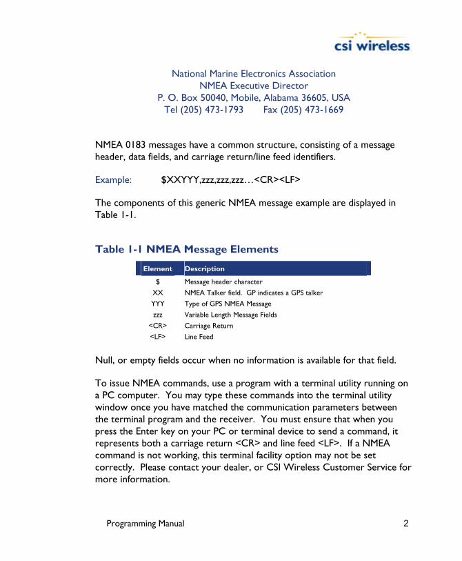
NMEA 0183 messages have a common structure, consisting of a message header, data fields, and carriage return/line feed identifiers.
Example: $XXYYY,zzz,zzz,zzz…<CR><LF>
The components of this generic NMEA message example are displayed in Table 1-1.
Table 1-1 NMEA Message Elements
Element Description
$ Message header character
XX NMEA Talker field. GP indicates a GPS talker
YYY Type of GPS NMEA Message
zzz Variable Length Message Fields
<CR> Carriage Return
<LF> Line Feed
Null, or empty fields occur when no information is available for that field.
To issue NMEA commands, use a program with a terminal utility running on a PC computer. You may type these commands into the terminal utility window once you have matched the communication parameters between the terminal program and the receiver. You must ensure that when you press the Enter key on your PC or terminal device to send a command, it represents both a carriage return <CR> and line feed <LF>. If a NMEA command is not working, this terminal facility option may not be set correctly. Please contact your dealer, or CSI Wireless Customer Service for more information.
Programming Manual 3
1.1.2 Binary Binary messages may be output from the DGPS MAX receiver, the Mini MAX receiver, the PowerMAX receiver, the Vector, the Vector PRO, the Vector Sensor, the Vector Sensor PRO and the Vector OEM along with NMEA 0183 data. Binary messages have a proprietary definition that likely will require custom software support if you wish to use it. Binary messages inherently are more efficient than NMEA 0183 and would be used when you require maximum communication efficiency. Use of binary messages for most users is not recommended as the NMEA interface allows you to control the operation of the receivers and also receive all necessary data regarding status and positioning information.
The receivers support a selection of binary data messages that provide improved communication port efficiency. Additionally, certain data is available only in binary format, such as raw measurement information.
Note - The binary messages described in this chapter are turned on or off using the $JBIN and $JOFF commands discussed in Chapters 3 and 4.
1.1.2.1 Binary Message Structure The Binary messages supported by the receivers are in an Intel Little Endian format for direct read in a PC environment. You can find more information on this format at the following Web site.
www.cs.umass.edu/~verts/cs32/endian.html
Each binary message begins with an 8-byte header and ends with a carriage-return line-feed pair (0x0D, 0x0A). The first four characters of the header is the ASCII sequence $BIN.
The following table provides the general binary message structure.

Programming Manual 4
Table 1-2 Binary Message Structure
Group Components Type Bytes Value
Synchronization String 4 byte string 4 $BIN
BlockID - a number which tells the type of binary message
Unsigned short
2 1, 2, 80, 93, 94, 95, 96, 97, 98, or 99
Header
DataLength - the length of the binary messages
Unsigned short
2 52, 16, 40, 56, 96, 128, 300, 28, 68, or 304
Data Binary Data - varying fields of data with a total length of DataLength bytes
Mixed fields 52, 16, 40, 56, 96, 128, 300, 28, 68, or 304
Varies - see message tables
Checksum - sum of all bytes of the data (all DataLength bytes). The sum is placed in a 2-byte integer
Unsigned short
2 Sum of data bytes
CR - Carriage return Byte 1 0D hex
Epilogue
LF - Line feed Byte 1 0A hex
The total length of the binary message packet is DataLength plus 12 (8 byte header, 2 byte checksum, and 2 bytes for CR, LF).
1.1.3 RTCM RTCM is a communications standard established by the marine industry. It has found use in the transmission of GPS corrections.
The Radio Technical Commission for Maritime Services publishes updates to the RTCM message standard. The latest RTCM standard is available through:
Programming Manual 5
Radio Technical Commission for Maritime Services 1800 Diagonal Road, Suite 600
Alexandria, Virginia 22314-2840, USA Tel: (703)684-4481 Fax: (703)836-4229
Website: www.rtcm.org
1.2 Communications
1.2.1 Terminal Programs A variety of terminal utility programs may be used for serial communication with the receivers, however, it’s important that the communication parameters between the program and the receiver be matched (match baud rate of terminal program to receiver with an 8 data bit, no parity, and 1 stop bit setting).
You must also ensure that when you press the PC computer’s Enter key to terminate a NMEA message, that the carriage return is appended with a line feed, as is required by NMEA.

Programming Manual 6
1.2.2 PocketMAX and PocketMAX PC CSI Wireless offers configuration utilities designed for use with CSI Wireless GPS products, including all of the products mentioned in this manual. As these utilities were not designed specifically for any one product alone, they support features not offered by every product, such as tracking of the OmniSTAR differential service and display of our Vector product’s true heading, however, the interface may be used for all I/O operations.
PocketMAX is a configuration program designed for PDAs with Windows PocketPC software that runs on PocketPC 2000, 2002 and 2003 platforms. PocketMAX PC runs on laptop and PC computers running the Microsoft Windows 95 or higher operating system.
This software offers you the following flexibility:
• Tune your beacon and WAAS receivers • Monitor beacon and WAAS reception • Configure GPS message output and port settings • Configure and monitor heading, time constants, etc. • Record various types of data
Programming Manual 7
The current versions of PocketMAX and PocketMAX PC, as well as their associated user manuals are available for download from our website at:
www.csi-wireless.com/products/software.shtml
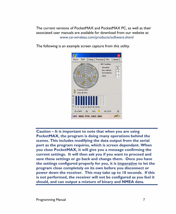
The following is an example screen capture from this utility.
Caution – It is important to note that when you are using PocketMAX, the program is doing many operations behind the scenes. This includes modifying the data output from the serial port as the program requires, which is screen dependant. When you close PocketMAX, it will give you a message confirming the current settings. It will then ask you if you want to proceed and save these settings or go back and change them. Once you have the settings configured properly for you, it is imperative to let the program close completely on its own before you disconnect or power down the receiver. This may take up to 10 seconds. If this is not performed, the receiver will not be configured as you feel it should, and can output a mixture of binary and NMEA data.

Programming Manual 8
2. Data Messages This chapter describes in detail, the GPS data messages supported by the DGPS MAX, the Mini MAX, the PowerMAX and the Vector receivers. The following table summarizes the data messages supported by these receivers.
Table 2-1 GPS NMEA Messages
Message Max Rate Description
GPGGA 5 Hz Global Positioning System Fix Data
GPGLL 5 Hz Geographic Position - Latitude/Longitude
GPGSA 1 Hz GNSS (Global Navigation Satellite System) DOP and Active Satellites
GPGST 1 Hz GNSS Pseudorange Error Statistics
GPGSV 1 Hz GNSS Satellites in View
GPRMC 5 Hz Recommended Minimum Specific GNSS Data
GPRRE 1 Hz Range residual message
GPVTG 5Hz Course Over Ground and Ground Speed
GPZDA 5 Hz Time and Date
RD1 1 Hz SBAS diagnostic information (proprietary NMEA message)
$PCSI,1 1 Hz This is a proprietary beacon status message
HDT 10 Hz This message provides the true heading
ROT 10 Hz This message provides rate of turn information
HPR 10 Hz This is a proprietary message with time, true heading, and pitch or roll
GBS 1 Hz This message is used to support Receiver Autonomous Integrity Monitoring
The following subsections provide detailed information relating to the use of each command.
2.1 GGA Data Message The GGA message contains detailed GPS position information, and is the most frequently used NMEA data message. In Table 2-2, the GGA data message is broken down into its components. This message takes the following form:
Programming Manual 9
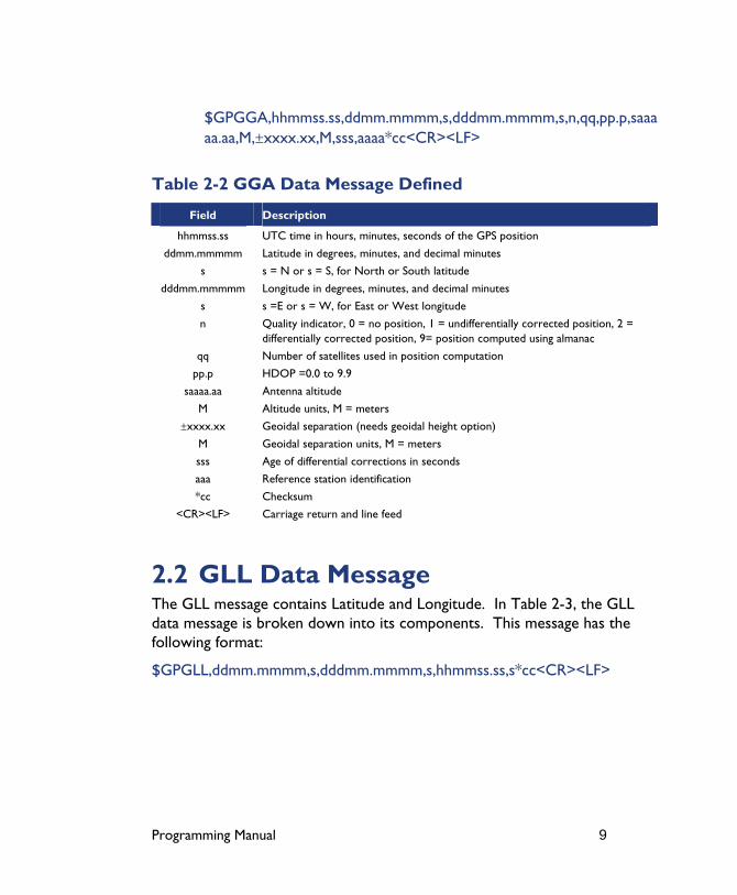
$GPGGA,hhmmss.ss,ddmm.mmmm,s,dddmm.mmmm,s,n,qq,pp.p,saaaaa.aa,M,±xxxx.xx,M,sss,aaaa*cc<CR><LF>
Table 2-2 GGA Data Message Defined
Field Description
hhmmss.ss UTC time in hours, minutes, seconds of the GPS position
ddmm.mmmmm Latitude in degrees, minutes, and decimal minutes
s s = N or s = S, for North or South latitude
dddmm.mmmmm Longitude in degrees, minutes, and decimal minutes
s s =E or s = W, for East or West longitude
n Quality indicator, 0 = no position, 1 = undifferentially corrected position, 2 = differentially corrected position, 9= position computed using almanac
qq Number of satellites used in position computation
pp.p HDOP =0.0 to 9.9
saaaa.aa Antenna altitude
M Altitude units, M = meters
±xxxx.xx Geoidal separation (needs geoidal height option)
M Geoidal separation units, M = meters
sss Age of differential corrections in seconds
aaa Reference station identification
*cc Checksum
<CR><LF> Carriage return and line feed
2.2 GLL Data Message The GLL message contains Latitude and Longitude. In Table 2-3, the GLL data message is broken down into its components. This message has the following format:
$GPGLL,ddmm.mmmm,s,dddmm.mmmm,s,hhmmss.ss,s*cc<CR><LF>
Programming Manual 10
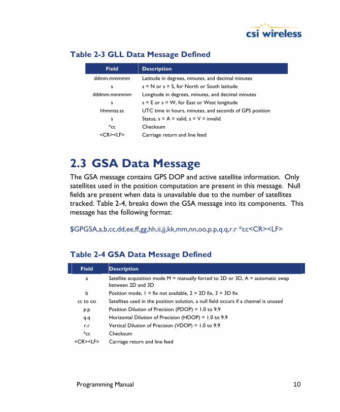
Table 2-3 GLL Data Message Defined
Field Description
ddmm.mmmmm Latitude in degrees, minutes, and decimal minutes
s s = N or s = S, for North or South latitude
dddmm.mmmmm Longitude in degrees, minutes, and decimal minutes
s s = E or s = W, for East or West longitude
hhmmss.ss UTC time in hours, minutes, and seconds of GPS position
s Status, s = A = valid, s = V = invalid
*cc Checksum
<CR><LF> Carriage return and line feed
2.3 GSA Data Message The GSA message contains GPS DOP and active satellite information. Only satellites used in the position computation are present in this message. Null fields are present when data is unavailable due to the number of satellites tracked. Table 2-4, breaks down the GSA message into its components. This message has the following format:
$GPGSA,a,b,cc,dd,ee,ff,gg,hh,ii,jj,kk,mm,nn,oo,p.p,q.q,r.r *cc<CR><LF>
Table 2-4 GSA Data Message Defined
Field Description
a Satellite acquisition mode M = manually forced to 2D or 3D, A = automatic swap between 2D and 3D
b Position mode, 1 = fix not available, 2 = 2D fix, 3 = 3D fix
cc to oo Satellites used in the position solution, a null field occurs if a channel is unused
p.p Position Dilution of Precision (PDOP) = 1.0 to 9.9
q.q Horizontal Dilution of Precision (HDOP) = 1.0 to 9.9
r.r Vertical Dilution of Precision (VDOP) = 1.0 to 9.9
*cc Checksum
<CR><LF> Carriage return and line feed

Programming Manual 11
2.4 GST Data Message The GST message contains Global Navigation Satellite System (GNSS) psuedorange error statistics. Table 2-5, breaks down the GST message into its components. This message has the following format:
$GPGST,hhmmss.ss,a.a,b.b,c.c,d.d,e.e,f.f,g.g *cc<CR><LF>
Table 2-5 GST Data Message Defined
Field Description
hhmmss.ss UTC time in hours, minutes, seconds of the GPS position
a.a Root mean square (rms) value of the standard deviation of the range inputs to the navigation process. Range inputs include pseudoranges and differential GNSS (DGNSS) corrections
b.b Standard deviation of semi-major axis of error ellipse (meters)
c.c Standard deviation of semi-minor axis of error ellipse (meters)
d.d Orientation of semi-major axis of error ellipse (meters)
e.e Standard deviation of latitude error (meters)
f.f Standard deviation of longitude error (meters)
g.g Standard deviation of altitude error (meters)
*cc Checksum
<CR><LF> Carriage return and line feed
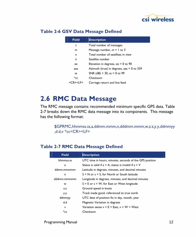
2.5 GSV Data Message The GSV message contains GPS satellite information. Null fields occur where data is not available due to the number of satellites tracked. Table 2-6 breaks down the GSV data message into its components. This message has the following format:
$GPGSV,t,m,n,ii,ee,aaa,ss,…ii,ee,aaa,ss,*cc<CR><LF>
Programming Manual 12
Table 2-6 GSV Data Message Defined
Field Description
t Total number of messages
m Message number, m = 1 to 3
n Total number of satellites in view
ii Satellite number
ee Elevation in degrees, ee = 0 to 90
aaa Azimuth (true) in degrees, aaa = 0 to 359
ss SNR (dB) + 30, ss = 0 to 99
*cc Checksum
<CR><LF> Carriage return and line feed
2.6 RMC Data Message The RMC message contains recommended minimum specific GPS data. Table 2-7 breaks down the RMC data message into its components. This message has the following format:
$GPRMC,hhmmss.ss,a,ddmm.mmm,n,dddmm.mmm,w,z.z,y.y,ddmmyy,d.d,v *cc<CR><LF>
Table 2-7 RMC Data Message Defined
Field Description
hhmmss.ss UTC time in hours, minutes, seconds of the GPS position
a Status is valid if a = A, status is invalid if a = V
ddmm.mmmmm Latitude in degrees, minutes, and decimal minutes
n S = N or s = S, for North or South latitude
dddmm.mmmmm Longitude in degrees, minutes, and decimal minutes
w S = E or s = W, for East or West longitude
z.z Ground speed in knots
y.y Track made good, referenced to true north
ddmmyy UTC date of position fix in day, month, year
d.d Magnetic Variation in degrees
v Variation sense v = E = East, v = W = West
*cc Checksum

Programming Manual 13
<CR><LF> Carriage return and line feed
2.7 RRE Data Message The RRE message contains the satellite range residuals and estimated position error. Table 2-8 breaks down the RRE data message into its components. This message has the following format:
$GPRRE,n,ii,rr…ii,rr,hhh.h,vvv.v *cc<CR><LF>
Table 2-8 RRE Data Message Defined
Field Description
n Number of satellites used in position computation
ii Satellite number
rr Range residual in meters
hhh.h Horizontal position error estimate in meters
vvv.v Vertical position error estimate in meters
*cc Checksum
<CR><LF> Carriage return and line feed
2.8 VTG Data Message The VTG message contains velocity and course information. Table 2-9 breaks down the VTG data message into its components. This message has the following format:
$GPVTG,ttt,c,ttt,c,ggg.gg,u,ggg,gg,u*cc<CR><LF>

Programming Manual 14
Table 2-9 VTG Data Message Defined
Field Description
ttt True course over ground, ttt = 000 to 359, in degrees
c True course over ground indicator, c = T always
ttt Magnetic course over ground, ttt = 000 to 359, in degrees
c Magnetic course over ground Indicator, always c = M
ggg.gg Speed over ground, 000 to 999 knots
u Speed over ground units, u = N = Nautical mile/h
ggg.gg Speed over ground, 000 to 999 km/h
u Speed over ground units, u = K = kilometer/h
*cc Checksum
<CR><LF> Carriage return and line feed
2.9 ZDA Data Message The ZDA message contains Universal Time information. Table 2-10 breaks down the ZDA data message into its components. This message has the following format:
$GPZDA,hhmmss.ss,dd,mm,yyyy,xx,yy*cc<CR><LF>
Table 2-10 ZDA Data Message Defined
Field Description
hhmmss.ss UTC time in hours, minutes, seconds of the GPS position
dd Day, dd = 0 to 31
mm Month, mm = 1 to 12
yyyy Year
xx Local zone description in hours, xx = -13 to 13
yy Local zone description in minutes, yy = 0 to 59
*cc Checksum
<CR><LF> Carriage return and line feed
Programming Manual 15
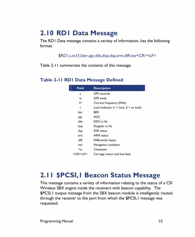
2.10 RD1 Data Message The RD1 Data message contains a variety of information, has the following format:
$RD1,s,w,f.f,l,ber,agc,dds,dop,dsp,arm,diff,nav<CR><LF>
Table 2-11 summarizes the contents of this message.
Table 2-11 RD1 Data Message Defined
Field Description
s GPS seconds
w GPS week
f.f Current frequency (MHz)
l Lock Indicator (1 = lock, 0 = no lock)
ber BER
agc AGC
dds DDS in Hz
dop Doppler in Hz
dsp DSP status
arm ARM status
diff Differential status
nav Navigation condition
*cc Checksum
<CR><LF> Carriage return and line feed
2.11 $PCSI,1 Beacon Status Message This message contains a variety of information relating to the status of a CSI Wireless SBX engine inside the receivers with beacon capability. The $PCSI,1 output message from the SBX beacon module is intelligently routed through the receiver to the port from which the $PCSI,1 message was requested.

Programming Manual 16
$PCSI,CS0,PXXX-Y.YYY,SN,fff.f,M,ddd,R,SS,SNR,MTP,Q,ID,H,T
Table 2-12 $PCSI,1 Beacon Status Message Defined
Field Description
CS0 Channel 0
PXXX-Y.YYY Resident SBX-3 firmware version
S/N SBX-3 receiver serial number
fff.f Channel 0 current frequency
M Frequency Mode (‘A’ - Auto or ‘M’ - Manual)
ddd MSK bit rate
R RTCM rate
SS Signal strength
SNR Signal to noise ratio
MTP Message throughput
Q Quality number {0-25} - number of successive good 30 bit RTCM words received
ID Beacon ID to which the receiver’s primary channel is tuned
H Health of the tuned beacon [0-7]
T $PCSI,1 status output period {0-99}
2.12 HDT Data Message This message provides true heading of the vessel. This is the direction that the vessel (Vector Antenna Array) is pointing and is not necessarily the direction of vessel motion (the course over ground). The HDT data message has the following format.
$HEHDT,x.x,T*cc<CR><LF>
Where ‘x.x’ is the current heading in degrees and ‘T’ indicates true heading.
2.13 ROT Data Message The ROT data message contains the vessel’s rate of turn information. It has the following format.

Programming Manual 17
$HEROT,x.x,A*cc<CR><LF>
Where ‘x.x’ is the rate of turn in degrees per minute and ‘A’ is a flag indicating that the data is valid. The ‘x.x’ field is negative when the vessel bow turns to port.
2.14 HPR Data Message The $PSAT,HPR message is a proprietary NMEA sentence that provides the heading, pitch / roll information, and time in a single data message. This message has the following format.
$PSAT,HPR,time,heading,pitch,roll,x*7B<CR><LF>
Table 2-13 HPR Data Message Defined
Field Description
time GPS time (HHMMSS.SS)
heading Heading (degrees)
pitch Pitch (degrees)
roll Roll (degrees)
x N when GPS is used to compute heading and G when gyro is being used to compute heading.
2.15 $PSAT,GBS Data Message The GBS message is used to support Receiver Autonomous Integrity Monitoring (RAIM). In Table 2-14, the GBS data message is broken down into its components. This message takes the following form:
$PSAT,GBS,hhmmss.ss,ll.l,LL.L,aa.a,ID,p.ppppp,b.b,s.s,flag*cc

Programming Manual 18
Table 2-14 $PSAT,GBS Data Message Defined
Field Description
hhmmss.ss UTC time in hours, minutes, seconds of the GGA or GNS fix associated with this sentence.
ll.l Expected error in latitude.
LL.L Expected error in longitude.
aa.a Expected error in altitude.
ID ID number of most likely failed satellite.
p.ppppp Probability of HPR fault.
b.b Estimate of range bias, in meters, on most likely failed satellite.
s.s Standard deviation of range bias estimate.
flag Good (0) / Warning (1) / Bad (2) Flag (based on horizontal protection radius)
*cc Checksum
Programming Manual 19
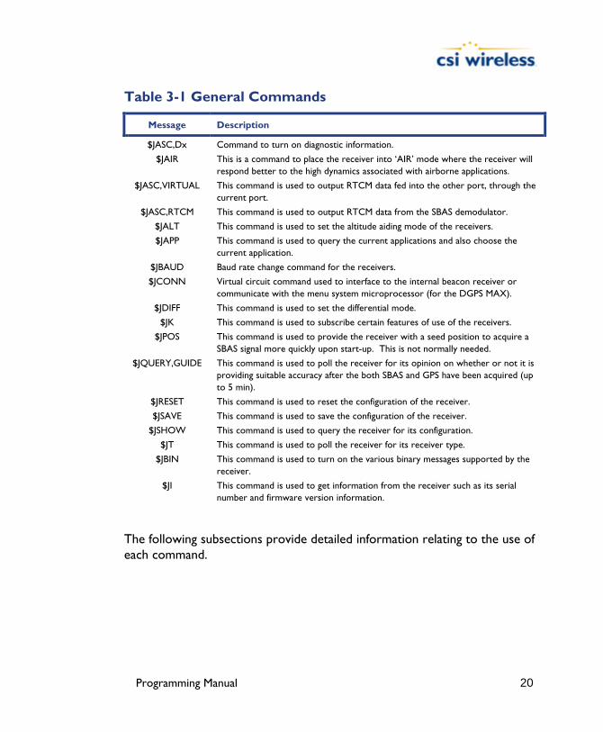
3. General Commands This section presents various commands relating to the general operation and configuration of the DGPS MAX, Mini MAX, PowerMAX, Vector, Vector PRO, Vector Sensor, Vector Sensor PRO and Vector OEM.
The following table provides a brief description of the general commands supported by these receivers.
Programming Manual 20
Table 3-1 General Commands
Message Description
$JASC,Dx Command to turn on diagnostic information.
$JAIR This is a command to place the receiver into ‘AIR’ mode where the receiver will respond better to the high dynamics associated with airborne applications.
$JASC,VIRTUAL This command is used to output RTCM data fed into the other port, through the current port.
$JASC,RTCM This command is used to output RTCM data from the SBAS demodulator.
$JALT This command is used to set the altitude aiding mode of the receivers.
$JAPP This command is used to query the current applications and also choose the current application.
$JBAUD Baud rate change command for the receivers.
$JCONN Virtual circuit command used to interface to the internal beacon receiver or communicate with the menu system microprocessor (for the DGPS MAX).
$JDIFF This command is used to set the differential mode.
$JK This command is used to subscribe certain features of use of the receivers.
$JPOS This command is used to provide the receiver with a seed position to acquire a SBAS signal more quickly upon start-up. This is not normally needed.
$JQUERY,GUIDE This command is used to poll the receiver for its opinion on whether or not it is providing suitable accuracy after the both SBAS and GPS have been acquired (up to 5 min).
$JRESET This command is used to reset the configuration of the receiver.
$JSAVE This command is used to save the configuration of the receiver.
$JSHOW This command is used to query the receiver for its configuration.
$JT This command is used to poll the receiver for its receiver type.
$JBIN This command is used to turn on the various binary messages supported by the receiver.
$JI This command is used to get information from the receiver such as its serial number and firmware version information.
The following subsections provide detailed information relating to the use of each command.

Programming Manual 21
Note - Please ensure that you save any changes that you wish to maintain beyond the current power-up by using the $JSAVE command and wait for the ‘$> Save Complete’ response.
3.1 $JASC,D1 This command allows you to adjust the output of the RD1 diagnostic information message from the receiver. The diagnostic information is specific to whichever differential source you are currently using.
This command has the following structure.
$JASC,Dx,r[,OTHER]<CR><LF>
Currently, only the RD1 message is currently defined with x = 1. The message status variable ‘r’ may be one of the following values.
r Description
0 OFF
1 ON
When the ‘,OTHER’ data field is specified (without the square brackets), this command will enact a change in the RD1 message on the other port.
3.2 $JAIR This command allows you to place the primary GPS engine within the receiver into AIR mode HIGH, where the receiver is optimized for the high dynamic environment associated with airborne platforms. JAIR defaults to normal (NORM) and this setting is recommended for most applications. Turning AIR mode on to HIGH is not recommended for Vector operation. The format of this command follows.
$JAIR,r<CR><LF>
Programming Manual 22
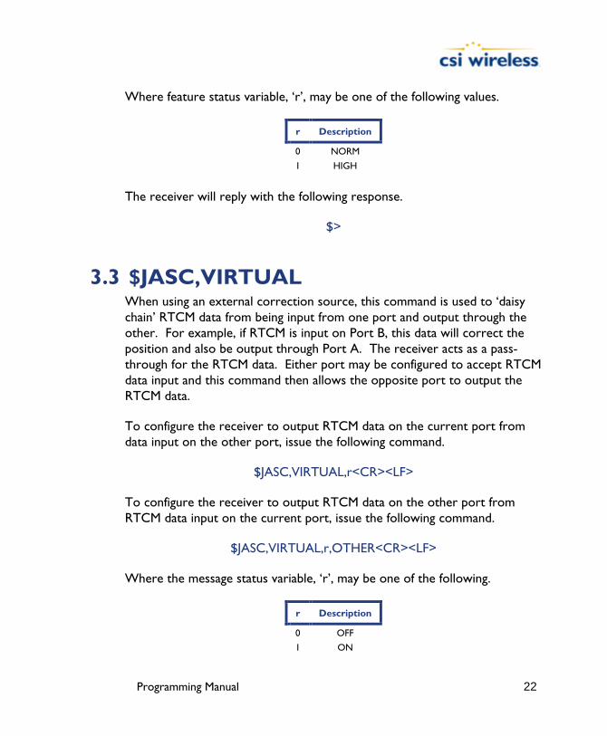
Where feature status variable, ‘r’, may be one of the following values.
r Description
0 NORM
1 HIGH
The receiver will reply with the following response.
$>
3.3 $JASC,VIRTUAL When using an external correction source, this command is used to ‘daisy chain’ RTCM data from being input from one port and output through the other. For example, if RTCM is input on Port B, this data will correct the position and also be output through Port A. The receiver acts as a pass-through for the RTCM data. Either port may be configured to accept RTCM data input and this command then allows the opposite port to output the RTCM data.
To configure the receiver to output RTCM data on the current port from data input on the other port, issue the following command.
$JASC,VIRTUAL,r<CR><LF>
To configure the receiver to output RTCM data on the other port from RTCM data input on the current port, issue the following command.
$JASC,VIRTUAL,r,OTHER<CR><LF>
Where the message status variable, ‘r’, may be one of the following.
r Description
0 OFF
1 ON
Programming Manual 23
The receiver will reply with the following response.
$>
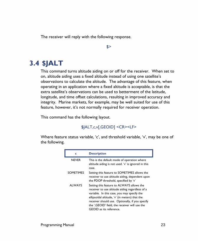
3.4 $JALT This command turns altitude aiding on or off for the receiver. When set to on, altitude aiding uses a fixed altitude instead of using one satellite’s observations to calculate the altitude. The advantage of this feature, when operating in an application where a fixed altitude is acceptable, is that the extra satellite’s observations can be used to betterment of the latitude, longitude, and time offset calculations, resulting in improved accuracy and integrity. Marine markets, for example, may be well suited for use of this feature, however, it’s not normally required for receiver operation.
This command has the following layout.
$JALT,c,v[,GEOID] <CR><LF>
Where feature status variable, ‘c’, and threshold variable, ‘v’, may be one of the following.
c Description
NEVER This is the default mode of operation where altitude aiding is not used. ‘v’ is ignored in this case.
SOMETIMES Setting this feature to SOMETIMES allows the receiver to use altitude aiding, dependent upon the PDOP threshold, specified by ‘v’
ALWAYS Setting this feature to ALWAYS allows the receiver to use altitude aiding regardless of a variable. In this case, you may specify the ellipsoidal altitude, ‘v’ (in meters) that the receiver should use. Optionally, if you specify the ‘,GEOID’ field, the receiver will use the GEOID as its reference.
Programming Manual 24
The receiver will reply with the following response.
$>
3.5 $JLIMIT This command is used to change the threshold of estimated horizontal performance for which the DGPS position LED is illuminated (only on the Mini MAX and PowerMAX). The default value for this parameter is a conservative 10.0 meters. This command has the following format.
$JLIMIT,limit<CR><LF>
Where ‘limit’ is the new limit in meters.
The receiver will respond with the following message.
$>
If you wish to verify the current $JLIMIT threshold, the response to the $JSHOW command provides this information.
3.6 $JAPP This command allows you to request the receiver for the currently installed applications and to choose which application to use. Both internal GPS engines each have two copies of their firmware in both application slots. This ensures that the application is not accidentally changed such that the receiver fails to function correctly.
To poll the receiver for the current applications, send the following message.
$JAPP<CR><LF>
There are no data fields to specify in this message. The receiver will respond with the following message.
Programming Manual 25
$>JAPP,current,other
Where ‘current’ indicates the current application in use and ‘other’ indicates the secondary application that is not in use currently. To change from the current application to the other application (when a two applications are present), issue the following command.
$JAPP,OTHER<CR><LF>
Note - Other derivatives of the $JAPP command are the $JAPP,1<CR><LF> and $JAPP,2<CR><LF> commands that can be used to set the receiver to use the first and second application. It’s best to follow up the sending of these commands with a $JAPP query to see which application is 1 or 2. These two commands are best used when upgrading the firmware inside the receiver, as the firmware upgrading utility uses the application number to designate which application to overwrite.
Note - When running an application, you can issue a $JI command to determine the version of that application.
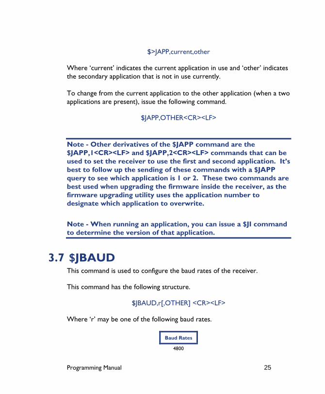
3.7 $JBAUD This command is used to configure the baud rates of the receiver.
This command has the following structure.
$JBAUD,r[,OTHER] <CR><LF>
Where ‘r’ may be one of the following baud rates.
Baud Rates
4800
Programming Manual 26
9600
19200
38400
When this command has been issued without the ‘,OTHER’ data field, the baud rate of the current port will be changed accordingly. When the ‘,OTHER’ data field is specified (without the square brackets), a baud rate change will occur for the other port.
The receiver will reply with the following response.
$>
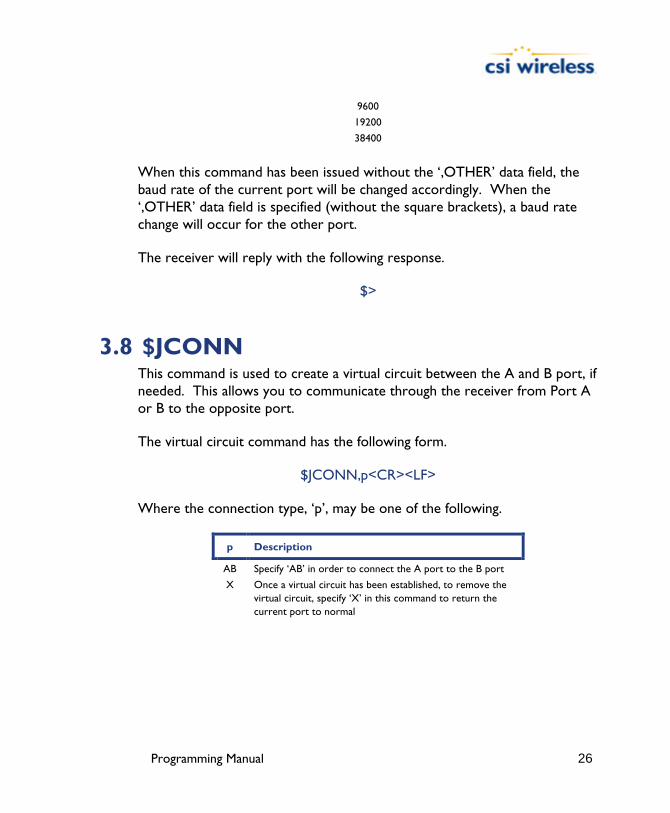
3.8 $JCONN This command is used to create a virtual circuit between the A and B port, if needed. This allows you to communicate through the receiver from Port A or B to the opposite port.
The virtual circuit command has the following form.
$JCONN,p<CR><LF>
Where the connection type, ‘p’, may be one of the following.
p Description
AB Specify ‘AB’ in order to connect the A port to the B port
X Once a virtual circuit has been established, to remove the virtual circuit, specify ‘X’ in this command to return the current port to normal

Programming Manual 27
3.9 $JDIFF This command is used to change the differential mode of the receiver. The default differential mode is SBAS (WAAS).
The structure of this command follows.
$JDIFF,diff<CR><LF>
Where the differential mode variable, ‘diff’, has one of the following values.
diff Description
OTHER Specifying OTHER instructs the receiver to use external corrections input through the opposite port from which you are communicating
BEACON Specifying BEACON instructs the receiver to use corrections from the internal SBX beacon engine
WAAS Specifying WAAS instructs the receiver to use SBAS corrections
LBAND Specifying LBAND instructs the receiver to use OmniSTAR corrections.
X Specifying X instructs the receiver to use e-Dif mode (the receiver will respond back with $JDIFF,AUTO to a $JDIFF query.)
NONE In order for the receiver to operate in autonomous mode, the NONE argument may be specified in this command.
3.10 $JK This command is used by the receiver to enable subscriptions for various features.
This command will have the following format.
$JK,x…<CR><LF>
Where ‘x…’ is the subscription key provided by CSI Wireless and is 10 characters in length.

Programming Manual 28
If you send the $JK command without a subscription key as follows, it will return the expiry date of the subscription.
$JK<CR><LF>
Reply.
$>JK,12/31/2003,1
3.11 $JPOS This command is used to speed up the initial acquisition when changing continents with the receiver (for example, powering it for the first time in Europe after it has been tested in Canada). This will allow it to begin the acquisition process for the closest SBAS spot beams. This will save some time with acquisition of the SBAS service; however, use of this message is typically not required due to the quick overall startup time of CSI receivers.
This command has the following layout.
$JPOS,lat,lon<CR><LF>
Where ‘lat’ and ‘lon’ have the following requirements.
Position Component Description
lat Latitude component must be entered in decimal degrees. This component does not have to be more accurate than half a degree.
lon Longitude component must be entered in decimal degrees. This component does not have to be more accurate than approximately half a degree.
Note - this command is not normally required for operation of CSI receivers.
Programming Manual 29
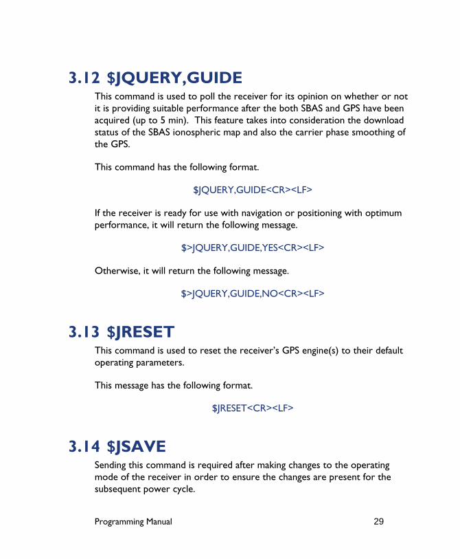
3.12 $JQUERY,GUIDE This command is used to poll the receiver for its opinion on whether or not it is providing suitable performance after the both SBAS and GPS have been acquired (up to 5 min). This feature takes into consideration the download status of the SBAS ionospheric map and also the carrier phase smoothing of the GPS.
This command has the following format.
$JQUERY,GUIDE<CR><LF>
If the receiver is ready for use with navigation or positioning with optimum performance, it will return the following message.
$>JQUERY,GUIDE,YES<CR><LF>
Otherwise, it will return the following message.
$>JQUERY,GUIDE,NO<CR><LF>
3.13 $JRESET This command is used to reset the receiver’s GPS engine(s) to their default operating parameters.
This message has the following format.
$JRESET<CR><LF>
3.14 $JSAVE Sending this command is required after making changes to the operating mode of the receiver in order to ensure the changes are present for the subsequent power cycle.
Programming Manual 30
$JATT commands do not require a $JSAVE command to be issued subsequently as their changes are automatically saved.
This command has the following structure.
$JSAVE<CR><LF>
The receiver will reply with the following two messages. Ensure that the receiver indicates that the save process is complete before turning the receiver off or changing the configuration further.
$> Saving Configuration. Please Wait...
$> Save Complete
No data fields are required. The receiver will indicate that the configuration is being saved and will notify you when the save is complete.
3.15 $JSHOW This command is used to poll the receiver for its current configuration.
This command has the following structure.
$JSHOW[,subset] <CR><LF>
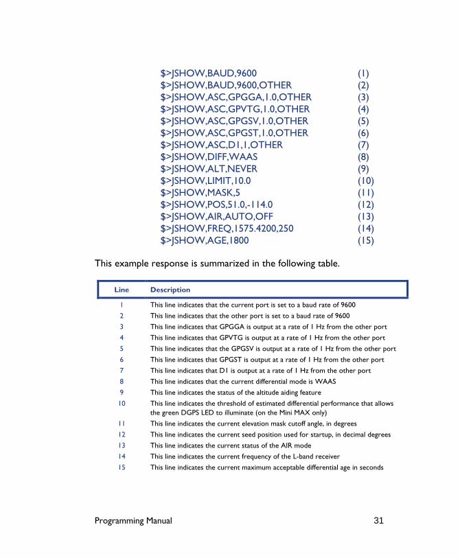
Using the $JSHOW command without the optional ‘,subset’ field will provide a complete response from the receiver. An example of this response follows.
Programming Manual 31
$>JSHOW,BAUD,9600 (1) $>JSHOW,BAUD,9600,OTHER (2) $>JSHOW,ASC,GPGGA,1.0,OTHER (3) $>JSHOW,ASC,GPVTG,1.0,OTHER (4) $>JSHOW,ASC,GPGSV,1.0,OTHER (5) $>JSHOW,ASC,GPGST,1.0,OTHER (6) $>JSHOW,ASC,D1,1,OTHER (7) $>JSHOW,DIFF,WAAS (8) $>JSHOW,ALT,NEVER (9) $>JSHOW,LIMIT,10.0 (10) $>JSHOW,MASK,5 (11) $>JSHOW,POS,51.0,-114.0 (12) $>JSHOW,AIR,AUTO,OFF (13) $>JSHOW,FREQ,1575.4200,250 (14) $>JSHOW,AGE,1800 (15)
This example response is summarized in the following table.
Line Description
1 This line indicates that the current port is set to a baud rate of 9600
2 This line indicates that the other port is set to a baud rate of 9600
3 This line indicates that GPGGA is output at a rate of 1 Hz from the other port
4 This line indicates that GPVTG is output at a rate of 1 Hz from the other port
5 This line indicates that the GPGSV is output at a rate of 1 Hz from the other port
6 This line indicates that GPGST is output at a rate of 1 Hz from the other port
7 This line indicates that D1 is output at a rate of 1 Hz from the other port
8 This line indicates that the current differential mode is WAAS
9 This line indicates the status of the altitude aiding feature
10 This line indicates the threshold of estimated differential performance that allows the green DGPS LED to illuminate (on the Mini MAX only)
11 This line indicates the current elevation mask cutoff angle, in degrees
12 This line indicates the current seed position used for startup, in decimal degrees
13 This line indicates the current status of the AIR mode
14 This line indicates the current frequency of the L-band receiver
15 This line indicates the current maximum acceptable differential age in seconds
Programming Manual 32
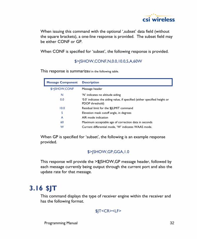
When issuing this command with the optional ‘,subset’ data field (without the square brackets), a one-line response is provided. The subset field may be either CONF or GP.
When CONF is specified for ‘subset’, the following response is provided.
$>JSHOW,CONF,N,0.0,10.0,5,A,60W
This response is summarized in the following table.
Message Component Description
$>JSHOW,CONF Message header
N ‘N’ indicates no altitude aiding
0.0 ‘0.0’ indicates the aiding value, if specified (either specified height or PDOP threshold)
10.0 Residual limit for the $JLIMIT command
5 Elevation mask cutoff angle, in degrees
A AIR mode indication
60 Maximum acceptable age of correction data in seconds
W Current differential mode, ‘W’ indicates WAAS mode.
When GP is specified for ‘subset’, the following is an example response provided.
$>JSHOW,GP,GGA,1.0
This response will provide the >$JSHOW,GP message header, followed by each message currently being output through the current port and also the update rate for that message.
3.16 $JT This command displays the type of receiver engine within the receiver and has the following format.
$JT<CR><LF>
Programming Manual 33
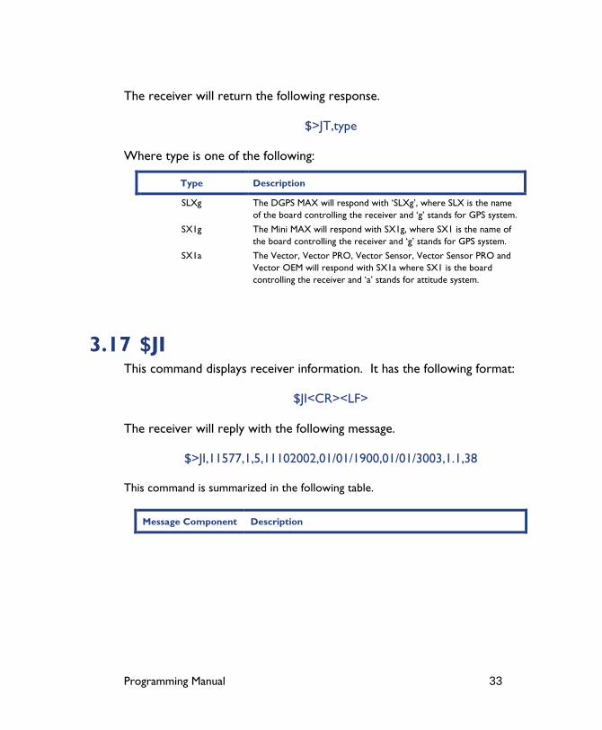
The receiver will return the following response.
$>JT,type
Where type is one of the following:
Type Description
SLXg The DGPS MAX will respond with ‘SLXg’, where SLX is the name of the board controlling the receiver and ‘g’ stands for GPS system.
SX1g The Mini MAX will respond with SX1g, where SX1 is the name of the board controlling the receiver and ‘g’ stands for GPS system.
SX1a The Vector, Vector PRO, Vector Sensor, Vector Sensor PRO and Vector OEM will respond with SX1a where SX1 is the board controlling the receiver and ‘a’ stands for attitude system.
3.17 $JI This command displays receiver information. It has the following format:
$JI<CR><LF>
The receiver will reply with the following message.
$>JI,11577,1,5,11102002,01/01/1900,01/01/3003,1.1,38
This command is summarized in the following table.
Message Component Description

Programming Manual 34
11577 This field provides the serial number of the GPS engine
1 This field is the fleet number
5 This is the hardware version
11102002 This field is the production date code
01/01/1900 This field is the subscription begin date
1/01/3003 This field is the Subscription expiration date
1.1 This field is the ARM version
38 This field is the DSP version
3.18 $JBIN This command allows you to request the output of the various binary messages. Binary messages 95 and 96 contain all information required for post processing.
This message has the following structure.
$JBIN,msg,r
Where ‘msg’ is the message name and ‘r’ is the message rate as shown in the table below.
msg r (Hz) Description
Bin1 5, 1, 0, or .2 Binary GPS position message.
Bin2 5, 1, 0, or .2 Binary message containing GPS DOP’s.
Bin80 1 or 0 Binary message containing SBAS information.
Bin95 1 or 0 Binary message containing ephemeris information.
Bin96 1 or 0 Binary message containing code and carrier phase information.
Bin97 5, 1, 0, or .2 Binary message containing process statistics
Bin98 1 or 0 Binary message containing satellite and almanac information.
Bin99 5, 1, 0, or .2 Binary message containing GPS diagnostic information.
The receiver will reply with the following response.
$>

Programming Manual 35
4. GPS Commands This section describes the selection of commands specific to the configuration and operation of the DGPS MAX, Mini MAX, PowerMAX, Vector, Vector PRO, Vector Sensor, Vector Sensor PRO and Vector OEM receivers.
The following table provides a brief description of the commands supported by the GPS engine for its configuration and operation.
Table 4-1 GPS Commands
Message Description
$JASC,GP This command is used to configure the NMEA message output of the GPS engine
$JAGE A command used to configure the maximum age of DGPS corrections
$JOFF This command is used to turn off all data output by the GPS engine
$JMASK This command allows you to modify the cut-off angle for tracking of GPS satellites
$J4STRING This command allows you to configure the GPS for output of the GPGGA, GPGSA, GPVTG, and GPZDA messages at a specific baud rate
$JRAIM This command is used to set and view the RAIM parameters
$JSMOOTH This command is used to change the carrier smoothing interval
The following subsections provide detailed information relating to the use of each command.
Note - Please ensure that you save any changes that you wish to maintain beyond the current power-up by using the $JSAVE command and wait for the ‘$> Save Complete’ response.
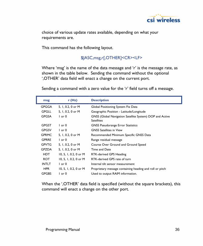
4.1 $JASC Using this command, you may turn GPS data messages on at a particular update rate or turn them off. When turning messages on, you have the
Programming Manual 36
choice of various update rates available, depending on what your requirements are.
This command has the following layout.
$JASC,msg,r[,OTHER]<CR><LF>
Where ‘msg’ is the name of the data message and ‘r’ is the message rate, as shown in the table below. Sending the command without the optional ‘,OTHER’ data field will enact a change on the current port.
Sending a command with a zero value for the ‘r’ field turns off a message.
msg r (Hz) Description
GPGGA 5, 1, 0.2, 0 or M Global Positioning System Fix Data
GPGLL 5, 1, 0.2, 0 or M Geographic Position - Latitude/Longitude
GPGSA 1 or 0 GNSS (Global Navigation Satellite System) DOP and Active Satellites
GPGST 1 or 0 GNSS Pseudorange Error Statistics
GPGSV 1 or 0 GNSS Satellites in View
GPRMC 5, 1, 0.2, 0 or M Recommended Minimum Specific GNSS Data
GPRRE 1 or 0 Range residual message
GPVTG 5, 1, 0.2, 0 or M Course Over Ground and Ground Speed
GPZDA 5, 1, 0.2, 0 or M Time and Date
HDT 10, 5, 1, 0.2, 0 or M RTK-derived GPS Heading
ROT 10, 5, 1, 0.2, 0 or M RTK-derived GPS rate of turn
INTLT 1 or 0 Internal tilt sensor measurement
HPR 10, 5, 1, 0.2, 0 or M Proprietary message containing heading and roll or pitch
GPGBS 1 or 0 Used to output RAIM information.
When the ‘,OTHER’ data field is specified (without the square brackets), this command will enact a change on the other port.
Programming Manual 37
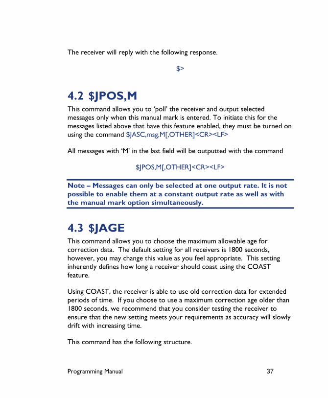
The receiver will reply with the following response.
$>
4.2 $JPOS,M This command allows you to ‘poll’ the receiver and output selected messages only when this manual mark is entered. To initiate this for the messages listed above that have this feature enabled, they must be turned on using the command $JASC,msg,M[,OTHER]<CR><LF>
All messages with ‘M’ in the last field will be outputted with the command
$JPOS,M[,OTHER]<CR><LF>
Note – Messages can only be selected at one output rate. It is not possible to enable them at a constant output rate as well as with the manual mark option simultaneously.
4.3 $JAGE This command allows you to choose the maximum allowable age for correction data. The default setting for all receivers is 1800 seconds, however, you may change this value as you feel appropriate. This setting inherently defines how long a receiver should coast using the COAST feature.
Using COAST, the receiver is able to use old correction data for extended periods of time. If you choose to use a maximum correction age older than 1800 seconds, we recommend that you consider testing the receiver to ensure that the new setting meets your requirements as accuracy will slowly drift with increasing time.
This command has the following structure.
Programming Manual 38
$JAGE,age<CR><LF>
Where maximum differential age timeout variable, ‘age’, may be a value from 6 to 8100 seconds.
The receiver will reply with the following response.
$>
4.4 $JOFF This command allows you to turn off all data messages being output through the current or other port, including any binary messages.
This command has the following definition.
$JOFF[,OTHER]<CR><LF>
When the ‘,OTHER’ data field is specified (without the square brackets), this command will turn on the four NMEA messages on the other port.
There are no variable data fields for this message. The receiver will reply with the following response.
$>
4.5 $JMASK This command allows you to change the elevation cutoff mask angle for the GPS engine. Any satellites below this mask angle will be ignored, even if available. The default angle is 5 degrees, as satellites available below this angle will have significant tropospheric refraction errors.
This message has the following format.
Programming Manual 39
$JMASK,e<CR><LF>
Where the elevation mask cutoff angle, ‘e’, may be a value from 0 to 60 degrees.
The receiver will reply with the following response.
$>
4.6 $JNP
This command allows the user to specify the number of decimal places output in the GGA and GLL messages.
This command has the following definition.
$JNP,x<CR><LF>
Where 'x' specifies the number of decimal places from 1 to 5. This command will affect both the GGA and the GLL messages.
4.7 $J4STRING This command allows the GPGGA, GPVTG, GPGSA, and GPZDA messages to all be output with the issue of a single command. The output rate of each message is limited to 1 Hz, however, you may choose to set the baud rate of the current or other port at the same time.
This command has the following definition.
$J4STRING[,r][,OTHER] <CR><LF>
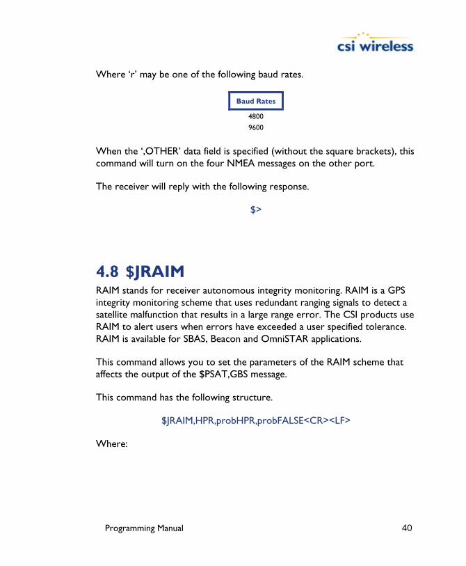
Programming Manual 40
Where ‘r’ may be one of the following baud rates.
Baud Rates
4800
9600
When the ‘,OTHER’ data field is specified (without the square brackets), this command will turn on the four NMEA messages on the other port.
The receiver will reply with the following response.
$>
4.8 $JRAIM RAIM stands for receiver autonomous integrity monitoring. RAIM is a GPS integrity monitoring scheme that uses redundant ranging signals to detect a satellite malfunction that results in a large range error. The CSI products use RAIM to alert users when errors have exceeded a user specified tolerance. RAIM is available for SBAS, Beacon and OmniSTAR applications.
This command allows you to set the parameters of the RAIM scheme that affects the output of the $PSAT,GBS message.
This command has the following structure.
$JRAIM,HPR,probHPR,probFALSE<CR><LF>
Where:

Programming Manual 41
Variable Description
HPR Horizontal Protection Radius (HPR). You will receive notification in the $PSAT,GBS message that the horizontal error has exceeded this amount. The acceptable range for this value is
from 1 to 10000 meters. The default is 10m.
probHPR Maximum allowed probability that the position computed lies outside the HPR. The acceptable range for this value is from 0.001% to 50%. The default is 5%.
probFALSE Maximum allowed probability that there is a false alarm (that is, that the position error is reported outside of the HPR, but it is really within the HPR. The acceptable range for this
value is from 0.001% to 50%. The default is 1%.
When the $JRAIM message is sent without any arguments, the response will show the current settings.
4.9 $JSMOOTH There is a new command, $JSMOOTH that enables the user to change the carrier smoothing interval between 15 minutes and 5 minutes. This command was designed to offer the user flexibility for tuning in different environments. You may find a slight improvement in positioning performance using either the short or long smoothing interval depending on your multipath environment. The default for this command is 15 minutes or LONG. To change the smoothing interval to 5 minutes or SHORT, use the following command.
$JSMOOTH,SHORT<CR><LF>
If you wish to change the smoothing interval to 15 minutes or LONG, use the following command.
$JSMOOTH,LONG<CR><LF>
If you wish to request the status of this message, send the following command. The status of this command is also output in the $JSHOW message.
$JSMOOTH<CR><LF>
Programming Manual 42
Note - If you are unsure of the best value for this setting, it’s best to be conservative and leave it at the default setting of LONG (15 minutes).

Programming Manual 43
5. WAAS Commands This section details the NMEA messages accepted by the internal WAAS engine of the DGPS MAX, Mini MAX, PowerMAX, Vector, Vector PRO, Vector Sensor, Vector Sensor PRO and Vector OEM receivers.
The following table provides a brief description of the commands supported by the WAAS demodulator for its control and operation.
Table 5-1 WAAS Commands
Message Description
$JWAASPRN This message is used to reconfigure the WAAS PRN numbers for use with other Space Based Augmentation Systems (SBAS)
$JGEO This command is used to poll the WAAS demodulator for information relating to your current location and WAAS satellites.
$JASC,RTCM This feature allows you to configure the receiver to output RTCM data from the WAAS demodulator.
$JASC,D1 This command is used to poll the receiver for WAAS diagnostic information
The following subsections provide detailed information relating to the use of each command.
Note - Please ensure that you save any changes that you wish to maintain beyond the current power-up by using the $JSAVE command
5.1 $JWAASPRN This command allows you to both poll the receiver for the WAAS PRNs in memory, and change them, if desired.
To poll the receiver for the current applications, send the following message:
$JWAASPRN<CR><LF>

Programming Manual 44
There are no data fields to specify in this message. The receiver will respond with the following message:
$>JWAASPRN,prn1,prn2
Where ‘prn1’ indicates the first PRN number and ‘prn2’ indicates the second PRN number. The PRN numbers for WAAS are 122 and 134. EGNOS is currently using PRN 120.
To change from the current PRN numbers, the following message should be used:
$JWAASPRN[,sv1[,sv2]] <CR><LF>
Where ‘sv1’ is the PRN number of the first SBAS satellite and ‘sv2’ is the PRN number of the second SBAS satellite. Either ‘sv1’ or both ‘sv1’ and ‘sv2’ may be specified.
The receiver will reply with the following response:
$>
5.2 $JGEO This message is used to display information related to the current frequency of WAAS, and its location in relation to the receiver’s antenna.
To query the receiver for the currently used WAAS satellite information, use the following query:
$JGEO<CR><LF>
The receiver will respond with the following data message:
$>JGEO,Sent=1575.4200,Used=1575.4200,PRN=prn,Lon=lon,El=ele,Az=az

Programming Manual 45
This message response is summarized in the following table:
Data Field Description
$>JGEO Message header.
Sent=1575.4200 Frequency sent to the digital signal processor
Used=1575.4200 Frequency currently used by the digital signal processor
PRN=prn WAAS satellite PRN number
Lon=-lon Longitude of the satellite
El=ele Elevation angle from the receiver’s antenna to the WAAS satellite, referenced to the horizon.
Az=az Azimuth from the receiver’s antenna to the WAAS satellite, referenced to the horizon.
To monitor this information for both WAAS satellites, add the ‘,ALL’ variable to the $JGEO message as follows:
$JGEO[,ALL] <CR><LF>
This will result in the following output messages:
$>JGEO,Sent=1575.4200,Used=1575.4200,PRN=122,Lon=-54,El=9.7,Az=114.0
$>JGEO,Sent=1575.4200,Used=1575.4200,PRN=134,Lon=178,El=5.0,Az=252.6
As can be seen from this output, the first message is identical to the output from the $JGEO query, however, the second message provides information on the WAAS satellite not being currently used. Both outputs follow the format in the previous table for the $JGEO query.
5.3 $JASC,RTCM This command allows you to configure the receiver to output, through the MAIN (for DGPS MAX, Mini MAX or PowerMAX) or Primary Master (for Vector products) port, correction data currently being used by one of the three internal sensors. The correction data output is RTCM SC-104 even though WAAS uses a different over-the-air protocol (RTCA)
Programming Manual 46
This message has the following layout:
$JASC,RTCM,r<CR><LF>
Note - Turning RTCM on or off using this command provides the same functionality as setting the RTCM menu item to on or off in the NMEA On/Off menu of the DGPS MAX.
The receiver will reply with the following response:
$>

Programming Manual 47
6. OmniSTAR Commands (for DGPS MAX only) This section presents the commands supported by the internal OmniSTAR sensor within the DGPS MAX.
The following table provides a brief description of the commands supported by the OmniSTAR sensor for its configuration and control.
Table 6-1 OmniSTAR Commands
Message Description
$JLBEAM This command requests the current spot beam tables in use by the OmniSTAR receiver
$JLXBEAM This command requests debug information for the current spot beam tables
$JOMS This command requests the OmniSTAR engine to provide the current subscription information for the OmniSTAR service.
$JOMR This command requests the OmniSTAR receiver to provide raw OmniSTAR region information.
$JFREQ This command allows you to tune the OmniSTAR receiver either in automatic mode or manually.
$JGEO This command requests information relating to the current frequency and location of the OmniSTAR satellite in relation the antenna of the DGPS MAX system.
The following subsections provide detailed information relating to the use of each command.
Note - Please ensure that you save any changes that you wish to maintain beyond the current power-up by using the $JSAVE command
6.1 $JLBEAM This command displays the current spot beams used by the OmniSTAR receiver inside the DGPS MAX.

Programming Manual 48
This command has the following layout:
$JLBEAM<CR><LF>
The receiver will output the following data:
$>JLBEAM,Sent frequency1,Used frequency2,Baud xxx,Geo xxx (1) $>JLBEAM,frequency1,longitude1,latitude1,symbol1,satlongitude1 (2)
.
.
. $>JLBEAM,frequencyn,longituden,latituden,baud,satlongituden
The first line of this output is described in the following table:
Data Field Description
$JLBEAM Message header.
Sent frequency This field provides the frequency sent to the digital signal processor.
Used frequency This field provides the frequency currently being used by the digital signal processor.
Baud xxxx This data field provides the currently used baud rate of the acquired signal.
Geo xxx This field provides the currently used satellite’s longitude, in degrees.
The second line, and those that follow, are described in the following table:
Data Field Description
$>JLBEAM Message Header.
frequency This data field provides the frequency of the spot beam
longitude This data field indicates the longitude of the center of the spot beam, in degrees.
latitude This data field indicates the latitude of the center of the spot beam, in degrees.
baud This field indicates the baud rate at which this spot beam is modulated.
satlongitude This data field provides the satellite’s longitude, in degrees.
An example of this response follows:
$>JLBEAM,Sent 1551.4890,Used 1551.4890,Baud 1200,Geo -101 $>JLBEAM,1556.8250,-88,45,1200,(-101)
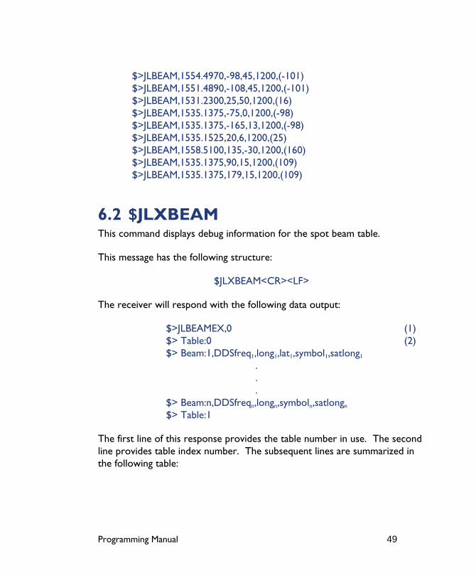
Programming Manual 49
$>JLBEAM,1554.4970,-98,45,1200,(-101) $>JLBEAM,1551.4890,-108,45,1200,(-101) $>JLBEAM,1531.2300,25,50,1200,(16) $>JLBEAM,1535.1375,-75,0,1200,(-98) $>JLBEAM,1535.1375,-165,13,1200,(-98) $>JLBEAM,1535.1525,20,6,1200,(25) $>JLBEAM,1558.5100,135,-30,1200,(160) $>JLBEAM,1535.1375,90,15,1200,(109) $>JLBEAM,1535.1375,179,15,1200,(109)
6.2 $JLXBEAM This command displays debug information for the spot beam table.
This message has the following structure:
$JLXBEAM<CR><LF>
The receiver will respond with the following data output:
$>JLBEAMEX,0 (1) $> Table:0 (2) $> Beam:1,DDSfreq1,long1,lat1,symbol1,satlong1
.
.
. $> Beam:n,DDSfreqn,longn,symboln,satlongn $> Table:1
The first line of this response provides the table number in use. The second line provides table index number. The subsequent lines are summarized in the following table:

Programming Manual 50
Data Field Description
DDSfreq This field provides the DDS frequency
long This variable is the longitude of the spot beam centroid
lat This field provides the latitude of the spot beam centroid
symbol This data field indicates the symbol rate used for that particular spot beam
satlong This field provides the longitude of the L-band satellite
An example of this response follows:
$>JLBEAMEX,0 $> Table:0 $> Beam:0,1753247034,-88,45,1200,-101 $> Beam:1,1750643210,-98,45,1200,-101 $> Beam:2,1747278819,-108,45,1200,-101 $> Beam:3,1724619511,25,50,1200,16 $> Beam:4,1728989976,-75,0,1200,-98 $> Beam:5,1728989976,-165,13,1200,-98 $> Beam:6,1729006753,20,6,1200,25 $> Beam:7,1755131675,135,-30,1200,160 $> Beam:8,1728989976,90,15,1200,109 $> Beam:9,1728989976,179,15,1200,109 $> Table:1
6.3 $JOMS This command requests the raw OmniSTAR subscription information and has the following form:
$JOMS
The receiver will respond with the following message:
$>JOMS,Opt,Source,Type,AccrReduction,StartDate,EndDate,HourGlass,ExtentionTime,LinkVector,SoftwareVersion

Programming Manual 51
This message is summarized in the following table
Data field Description
Opt This field indicates a WET or DRY subscription
Source RTCM source ID or ALL if VBS
AccrReduction 0 is most accurate
StartDate Subscription start date
EndDate Subscription end date
HourGlass Seconds of metered time
Extention Time Seconds of extension
LinkVector hexadecimal mask of links
SoftwareVersion This item shows the OmniSTAR library version
An example of this response follows:
$>JOMS,DRY,ALL,VBS,0,01/06/2000,01/06/2001,0,0,1E00,1.43
6.4 $JOMR This command displays raw OmniSTAR region information and has the following structure:
$JOMR
The receiver will respond with the following messages:
$JOMR,1,latitude1,longitude1,radius1<CR><LF> $JOMR,2,latitude2,longitude2,radius2<CR><LF> $JOMR,3,latitude3,longitude3,radius3<CR><LF> $JOMR,4,latitude4,longitude4,radius4<CR><LF> $JOMR,5,latitude5,longitude5,radius5<CR><LF>
Where latitude and longitude are expressed in radians and the radius is in meters.

Programming Manual 52
If your receiver has an active subscription, the first line should show the inclusion area. The subsequent lines will show additional inclusion and/or exclusion areas. A negative radius indicates that the region is an exclusion zone. An example follows:
$>JOMR,1,.994787,-1.605694,4500000.000 $>JOMR,2,0.000000,0.000000,0.000000 $>JOMR,3,0.000000,0.000000,0.000000 $>JOMR,4,0.000000,0.000000,0.000000 $>JOMR,5,0.000000,0.000000,0.000000
6.5 $JFREQ This message allows you to either manually or automatically tune the OmniSTAR receiver inside the DGPS MAX.
This command has the following structure:
$JFREQ,freq,symb<CR><LF>
Where ‘freq’ is the frequency in kHz and ‘symb’ is the symbol rate (1200 or 2400 baud).
The DGPS MAX will reply with the following response:
$>
Entering a frequency of zero with no associated symbol rate will place the OmniSTAR engine into automatic mode. Entering a valid frequency and symbol rate will manually tune the receiver.
The following table provides frequency information for the OmniSTAR satellites.
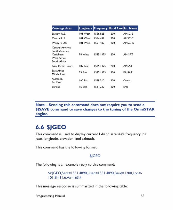
Programming Manual 53
Coverage Area Longitude Frequency Baud Rate Sat. Name
Eastern U.S. 101 West 1556.825 1200 AMSC-E
Central U.S 101 West 1554.497 1200 AMSC-C
Western U.S. 101 West 1551.489 1200 AMSC-W
Central America, South America, Caribbean, West Africa, South Africa
98 West 1535.1375 1200 AM-SAT
Asia, Pacific Islands 109 East 1535.1375 1200 AP-SAT
East Africa Middle East
25 East 1535.1525 1200 EA-SAT
Australia, Far East
160 East 1558.510 1200 Optus
Europe 16 East 1531.230 1200 EMS
Note – Sending this command does not require you to send a $JSAVE command to save changes to the tuning of the OmniSTAR engine.
6.6 $JGEO This command is used to display current L-band satellite’s frequency, bit rate, longitude, elevation, and azimuth.
This command has the following format:
$JGEO
The following is an example reply to this command:
$>JGEO,Sent=1551.4890,Used=1551.4890,Baud=1200,Lon=-101,El=31.6,Az=163.4
This message response is summarized in the following table:

Programming Manual 54
Data Field Description
$>JGEO Message header.
Sent=1551.4890 Frequency sent to the digital signal processor
Used=1551.4890 Frequency currently used by the digital signal processor
Baud=1200 WAAS satellite PRN number
Lon=-101 Longitude of the satellite
El=31 Elevation angle from the DGPS MAX’s antenna to the WAAS satellite, referenced to the horizon.
Az=163.4 Azimuth from the DGPS MAX’s antenna to the WAAS satellite, referenced to the horizon.

Programming Manual 55
7. Beacon Commands (for all receivers excluding Vector and Vector Sensor) This section details the commands supported by the DGPS MAX, Mini MAX, PowerMAX, Vector PRO, Vector Sensor PRO and Vector OEM PRO’s internal SBX beacon engine.
The following table provides a brief description of the commands supported by this engine for control of its configuration and operation.
Table 7-1 Beacon Commands
Message Description
$JASC,BEAC This command instructs the receiver to output beacon RTCM data when in beacon mode
$GPMSK You may use this message to manually or automatically tune the beacon receiver
$PCSI,0 This command allows you to request a listing of available beacon commands
$PCSI,1 Issuing this query will cause the beacon receiver to return a channel 0 status message
$PCSI,2 Issuing this query will cause the beacon receiver to return a channel 1 status message
$PCSI,3 This command polls the beacon receiver for its search data
$PCSI,4 This command is used to erase automatic search data, forcing a new search to begin
$GPCRQ This query allows you to request either signal status or frequency status data
$CRMSS This message provides signal status data
$CRMSK This message provides frequency status data
The following subsections provide detailed information relating to the use of each command.
Note - The beacon receiver does not require a save command in order to maintain its settings. Changes to its configuration are automatically saved to memory.
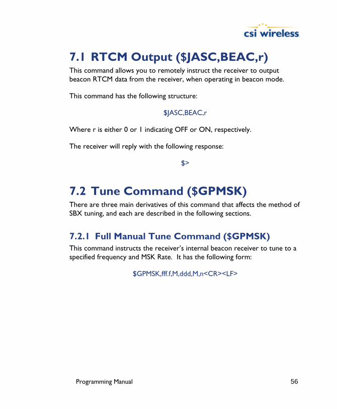
Programming Manual 56
7.1 RTCM Output ($JASC,BEAC,r) This command allows you to remotely instruct the receiver to output beacon RTCM data from the receiver, when operating in beacon mode.
This command has the following structure:
$JASC,BEAC,r
Where r is either 0 or 1 indicating OFF or ON, respectively.
The receiver will reply with the following response:
$>
7.2 Tune Command ($GPMSK) There are three main derivatives of this command that affects the method of SBX tuning, and each are described in the following sections.
7.2.1 Full Manual Tune Command ($GPMSK) This command instructs the receiver’s internal beacon receiver to tune to a specified frequency and MSK Rate. It has the following form:
$GPMSK,fff.f,M,ddd,M,n<CR><LF>
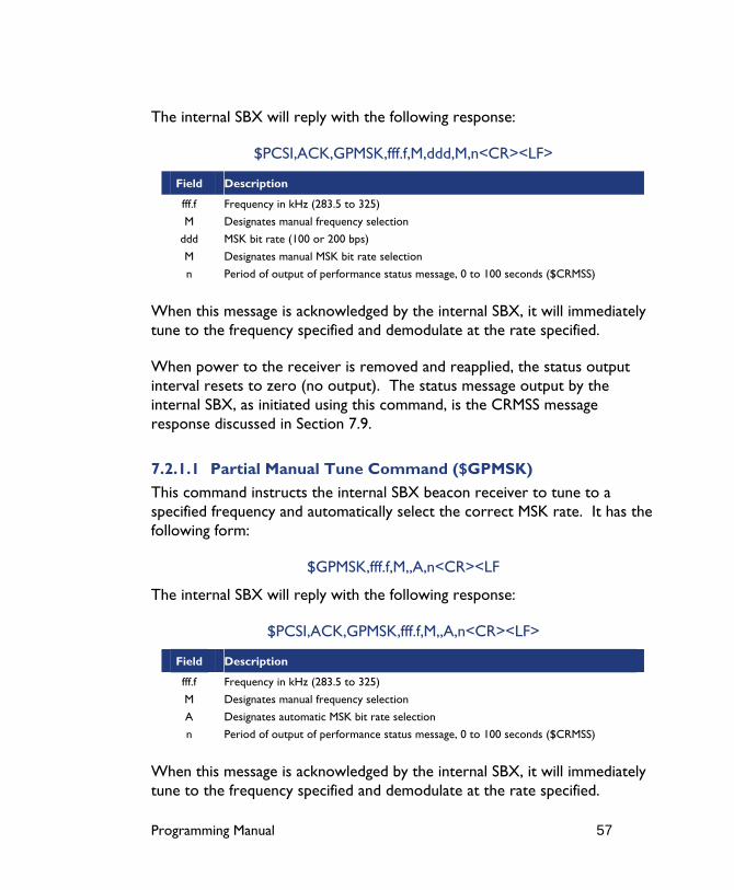
Programming Manual 57
The internal SBX will reply with the following response:
$PCSI,ACK,GPMSK,fff.f,M,ddd,M,n<CR><LF>
Field Description
fff.f Frequency in kHz (283.5 to 325)
M Designates manual frequency selection
ddd MSK bit rate (100 or 200 bps)
M Designates manual MSK bit rate selection
n Period of output of performance status message, 0 to 100 seconds ($CRMSS)
When this message is acknowledged by the internal SBX, it will immediately tune to the frequency specified and demodulate at the rate specified.
When power to the receiver is removed and reapplied, the status output interval resets to zero (no output). The status message output by the internal SBX, as initiated using this command, is the CRMSS message response discussed in Section 7.9.
7.2.1.1 Partial Manual Tune Command ($GPMSK) This command instructs the internal SBX beacon receiver to tune to a specified frequency and automatically select the correct MSK rate. It has the following form:
$GPMSK,fff.f,M,,A,n<CR><LF
The internal SBX will reply with the following response:
$PCSI,ACK,GPMSK,fff.f,M,,A,n<CR><LF>
Field Description
fff.f Frequency in kHz (283.5 to 325)
M Designates manual frequency selection
A Designates automatic MSK bit rate selection
n Period of output of performance status message, 0 to 100 seconds ($CRMSS)
When this message is acknowledged by the internal SBX, it will immediately tune to the frequency specified and demodulate at the rate specified.
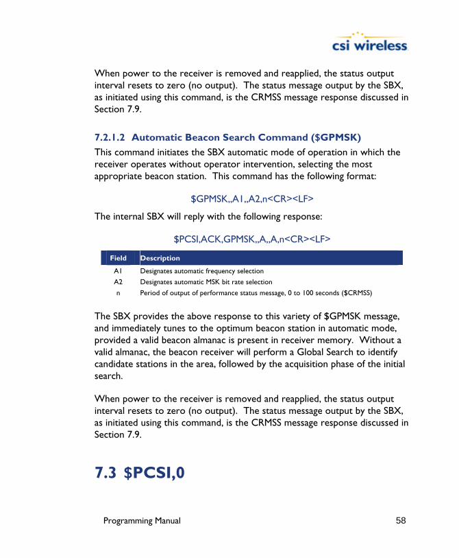
Programming Manual 58
When power to the receiver is removed and reapplied, the status output interval resets to zero (no output). The status message output by the SBX, as initiated using this command, is the CRMSS message response discussed in Section 7.9.
7.2.1.2 Automatic Beacon Search Command ($GPMSK) This command initiates the SBX automatic mode of operation in which the receiver operates without operator intervention, selecting the most appropriate beacon station. This command has the following format:
$GPMSK,,A1,,A2,n<CR><LF>
The internal SBX will reply with the following response:
$PCSI,ACK,GPMSK,,A,,A,n<CR><LF>
Field Description
A1 Designates automatic frequency selection
A2 Designates automatic MSK bit rate selection
n Period of output of performance status message, 0 to 100 seconds ($CRMSS)
The SBX provides the above response to this variety of $GPMSK message, and immediately tunes to the optimum beacon station in automatic mode, provided a valid beacon almanac is present in receiver memory. Without a valid almanac, the beacon receiver will perform a Global Search to identify candidate stations in the area, followed by the acquisition phase of the initial search.
When power to the receiver is removed and reapplied, the status output interval resets to zero (no output). The status message output by the SBX, as initiated using this command, is the CRMSS message response discussed in Section 7.9.
7.3 $PCSI,0

Programming Manual 59
This command queries the receiver for the list of available proprietary $PCSI commands. It has the following form:
$PCSI,0<CR><LF>
The internal SBX will reply with the following response:
$PCSI,0 $PCSI,ACK,0 $PCSI,P021-0,001 $PCSI,0 ->HELP Msg $PCSI,1 ->Status line A,<T>,<S> $PCSI,2 ->Status line B,<T> $PCSI,3 ->Dump Search $PCSI,4 ->Wipe Search $PCSI,5 ->Port Rate,<P0>,<P1> $PCSI,6 ->Reserved $PCSI,7 ->RTCM Mode
7.4 Status Line A, Channel 0 ($PCSI,1) This query requests the SBX to output a selection of parameters related to the operational status of its primary channel. It has the following format:
$PCSI,1<CR><LF>
The internal SBX will reply with the following response:
$PCSI,ACK,1 $PCSI,CS0,PXXX-Y.YYY,SN,fff.f,M,ddd,R,SS,SNR,MTP,Q,ID,H,T
The SBX will return the above response message when queried for its full channel status.
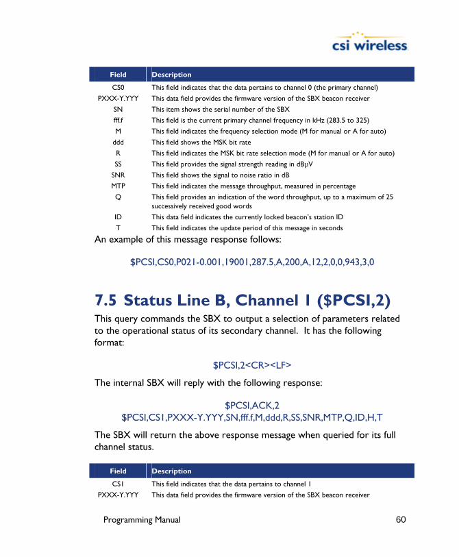
Programming Manual 60
Field Description
CS0 This field indicates that the data pertains to channel 0 (the primary channel)
PXXX-Y.YYY This data field provides the firmware version of the SBX beacon receiver
SN This item shows the serial number of the SBX
fff.f This field is the current primary channel frequency in kHz (283.5 to 325)
M This field indicates the frequency selection mode (M for manual or A for auto)
ddd This field shows the MSK bit rate
R This field indicates the MSK bit rate selection mode (M for manual or A for auto)
SS This field provides the signal strength reading in dBµV
SNR This field shows the signal to noise ratio in dB
MTP This field indicates the message throughput, measured in percentage
Q This field provides an indication of the word throughput, up to a maximum of 25 successively received good words
ID This data field indicates the currently locked beacon’s station ID
T This field indicates the update period of this message in seconds
An example of this message response follows:
$PCSI,CS0,P021-0.001,19001,287.5,A,200,A,12,2,0,0,943,3,0
7.5 Status Line B, Channel 1 ($PCSI,2) This query commands the SBX to output a selection of parameters related to the operational status of its secondary channel. It has the following format:
$PCSI,2<CR><LF>
The internal SBX will reply with the following response:
$PCSI,ACK,2 $PCSI,CS1,PXXX-Y.YYY,SN,fff.f,M,ddd,R,SS,SNR,MTP,Q,ID,H,T
The SBX will return the above response message when queried for its full channel status.
Field Description
CS1 This field indicates that the data pertains to channel 1
PXXX-Y.YYY This data field provides the firmware version of the SBX beacon receiver

Programming Manual 61
SN This item shows the serial number of the SBX
fff.f This field is the current secondary channel frequency in kHz (283.5 to 325)
M This field indicates the frequency selection mode (M for manual or A for auto)
ddd This field shows the MSK bit rate
R This field indicates the MSK bit rate selection mode (M for manual or A for auto)
SS This field provides the signal strength reading in dBµV
SNR This field shows the signal to noise ratio in dB
MTP This field indicates the message throughput, measured in percentage
Q This field provides an indication of the word throughput, up to a maximum of 25 successively received good words
ID This data field indicates the currently locked beacon’s station ID
T This field indicates the update period of this message in seconds
An example of this message response follows:
$PCSI,CS1,P021-0.001,19001,287.5,A,200,A,12,2,0,0,943,3,0
7.6 Search Dump ($PCSI,3) This query instructs the SBX to display the search information used for beacon selection in Automatic Beacon Search mode. The output has three frequencies per line.
$PCSI,3<CR><LF>
The SBX will reply with the following output:
$PCSI,ACK,3 $PCSI,index1,freq1,ID1,ch1,snr1,ss1,index2,freq2,ID2,ch2,snr2,ss2,index3,freq3,ID3,ch3,snr3,ss3
.
.
. $PCSI,index82,freq82,ID82,ch83,snr83,ss83,index83,freq83,ID83,ch83,snr83,ss83,index84,freq84,ID84,ch84,snr84,ss84
This message is summarized in the following table:

Programming Manual 62
Field Description
index1 to index84 This field indicates the channel number from 1 to 84 channels
freq This field indicates the frequency corresponding to the index number
ID This field shows the latest station ID of a beacon corresponding to the frequency
ch This field is an internal status flag
snr This field indicates the signal to noise ration in dB that was last measured for that beacon
ss This field indicates the signal strength last measured for that beacon in dBµV
An example of this message response follows:
$PCSI,ACK,3 $PCSI,01,2835,000,0E,03,0007,02,2840,000,0E,02,0008,03,2845,000,0E,03,0008 $PCSI,04,2850,000,0E,02,0008,05,2855,000,0E,03,0009,06,2860,000,0E,05,0014 $PCSI,07,2865,000,0E,02,0008,08,2870,060,0F,17,0023,09,2875,000,0E,01,0011 $PCSI,10,2880,000,0E,02,0012,11,2885,000,0E,02,0009,12,2890,000,0E,02,0009 $PCSI,13,2895,000,0E,01,0008,14,2900,000,0E,02,0012,15,2905,000,0E,03,0013 $PCSI,16,2910,000,0E,02,0017,17,2915,000,0E,02,0012,18,2920,000,0E,03,0014 $PCSI,19,2925,000,0E,-100,0012,20,2930,000,0E,-100,0018,21,2935,000,0E,-100,0009 $PCSI,22,2940,000,0E,-100,0014,23,2945,000,0E,-100,0011,24,2950,000,0E,-100,0011 $PCSI,25,2955,000,0E,-100,0008,26,2960,000,0E,-100,0009,27,2965,000,0E,-100,0011 $PCSI,28,2970,000,0E,-100,0012,29,2975,000,0E,-100,0012,30,2980,429,0E,-100,0009 $PCSI,31,2985,000,0E,-100,0013,32,2990,000,0F,06,0044,33,2995,000,0F,00,0013 $PCSI,34,3000,000,0F,03,0013,35,3005,733,0E,-100,0011,36,3010,000,0E,-100,0009 $PCSI,37,3015,000,0E,-100,0009,38,3020,000,0E,-100,0015,39,3025,000,0E,-100,0011 $PCSI,40,3030,000,0E,-100,0013,41,3035,000,0E,-100,0009,42,3040,282,0E,-100,0011 $PCSI,43,3045,000,0E,-100,0013,44,3050,000,0F,05,0023,45,3055,000,0E,-100,0012 $PCSI,46,3060,000,0E,-100,0012,47,3065,000,0E,-100,0013,48,3070,000,0E,-100,0008 $PCSI,49,3075,000,0E,-100,0012,50,3080,000,0E,-100,0017,51,3085,000,0E,-100,0013 $PCSI,52,3090,000,0E,-100,0009,53,3095,000,0E,-100,0009,54,3100,000,0E,-100,0017 $PCSI,55,3105,000,0E,-100,0014,56,3110,023,0E,-100,0017,57,3115,000,0E,-100,0011 $PCSI,58,3120,620,0E,-100,0012,59,3125,000,0E,-100,0012,60,3130,062,0E,-100,0022 $PCSI,61,3135,000,02,-100,0013,62,3140,345,0A,-100,0012,63,3145,000,02,-100,0011 $PCSI,64,3150,000,02,-100,0011,65,3155,000,0A,-100,0011,66,3160,000,0A,-100,0016 $PCSI,67,3165,000,0A,-100,0011,68,3170,000,0A,-100,0013,69,3175,000,0A,-100,0012 $PCSI,70,3180,000,0A,-100,0011,71,3185,000,0A,-100,0013,72,3190,000,0A,-100,0013 $PCSI,73,3195,000,0A,-100,0013,74,3200,000,0B,05,0032,75,3205,000,0B,00,0024 $PCSI,76,3210,000,02,-100,0017,77,3215,000,02,-100,0014,78,3220,000,02,-100,0014 $PCSI,79,3225,000,02,-100,0011,80,3230,000,0A,-100,0019,81,3235,684,0A,-100,0011
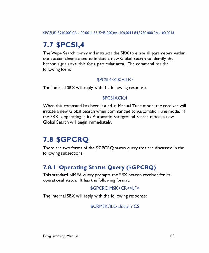
Programming Manual 63
$PCSI,82,3240,000,0A,-100,0011,83,3245,000,0A,-100,0011,84,3250,000,0A,-100,0018
7.7 $PCSI,4 The Wipe Search command instructs the SBX to erase all parameters within the beacon almanac and to initiate a new Global Search to identify the beacon signals available for a particular area. The command has the following form:
$PCSI,4<CR><LF>
The internal SBX will reply with the following response:
$PCSI,ACK,4
When this command has been issued in Manual Tune mode, the receiver will initiate a new Global Search when commanded to Automatic Tune mode. If the SBX is operating in its Automatic Background Search mode, a new Global Search will begin immediately.
7.8 $GPCRQ There are two forms of the $GPCRQ status query that are discussed in the following subsections.
7.8.1 Operating Status Query ($GPCRQ) This standard NMEA query prompts the SBX beacon receiver for its operational status. It has the following format:
$GPCRQ,MSK<CR><LF>
The internal SBX will reply with the following response:
$CRMSK,fff.f,x,ddd,y,n*CS
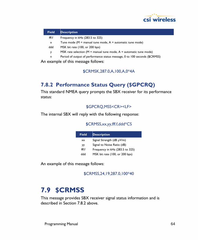
Programming Manual 64
Field Description
fff.f Frequency in kHz (283.5 to 325)
x Tune mode (M = manual tune mode, A = automatic tune mode)
ddd MSK bit rate (100, or 200 bps)
y MSK rate selection (M = manual tune mode, A = automatic tune mode)
n Period of output of performance status message, 0 to 100 seconds ($CRMSS)
An example of this message follows:
$CRMSK,287.0,A,100,A,0*4A
7.8.2 Performance Status Query ($GPCRQ) This standard NMEA query prompts the SBX receiver for its performance status:
$GPCRQ,MSS<CR><LF>
The internal SBX will reply with the following response:
$CRMSS,xx,yy,fff.f,ddd*CS
Field Description
xx Signal Strength (dB µV/m)
yy Signal to Noise Ratio (dB)
fff.f Frequency in kHz (283.5 to 325)
ddd MSK bit rate (100, or 200 bps)
An example of this message follows:
$CRMSS,24,19,287.0,100*40
7.9 $CRMSS This message provides SBX receiver signal status information and is described in Section 7.8.2 above.
Programming Manual 65
7.10 $CRMSK This message provides SBX receiver frequency status information and is described in Section 7.8.1 above.

Programming Manual 66
8. Heading Commands (for Vector products only) This section details the various settings that relate to the GPS heading aspect of the Vector, Vector PRO, Vector Sensor, Vector Sensor PRO and Vector OEM heading systems.
The following table summarizes the commands detailed in this section.
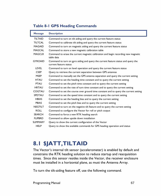
Programming Manual 67
Table 8-1 GPS Heading Commands
Message Description
TILTAID Command to turn on tilt aiding and query the current feature status
TILTCAL Command to calibrate tilt aiding and query the current feature status
MAGAID Command to turn on magnetic aiding and query the current feature status
MAGCAL Command to store a new magnetic calibration table
MAGCLR Command to erase the current magnetic calibration and begin recording new magnetic table data
GYROAID Command to turn on gyro aiding and query the current feature status and query the current feature status
LEVEL Command to turn on level operation and query the current feature status
CSEP Query to retrieve the current separation between GPS antennas
MSEP Command to manually set the GPS antenna separation and query the current setting
HTAU Command to set the heading time constant and to query the current setting
PTAU Command to set the pitch time constant and to query the current setting
HRTAU Command to set the rate of turn time constant and to query the current setting
COGTAU Command to set the course over ground time constant and to query the current setting
SPDTAU Command to set the speed time constant and to query the current setting
HBIAS Command to set the heading bias and to query the current setting
PBIAS Command to set the pitch bias and to query the current setting
NEGTILT Command to turn on the negative tilt feature and to query the current setting
ROLL Command to configure the Vector for roll or pitch output
SEARCH Command to force a new RTK heading search
FLIPBRD Command to allow upside down installation
SUMMARY Query to show the current configuration of the Vector
HELP Query to show the available commands for GPS heading operation and status
8.1 $JATT,TILTAID The Vector’s internal tilt sensor (accelerometer) is enabled by default and constrains the RTK heading solution to reduce startup and reacquisition times. Since this sensor resides inside the Vector, the receiver enclosure must be installed in a horizontal plane, as must the Antenna Array.
To turn the tilt-aiding feature off, use the following command.

Programming Manual 68
$JATT,TILTAID,NO<CR><LF>
You may turn this feature back on with the following command.
$JATT,TILTAID,YES,<CR><LF>
To query the Vector for the current status of this feature, issue the following command.
$JATT,TILTAID<CR><LF>
Note - If you choose to increase the antenna separation of your Vector Sensor or Vector OEM beyond the default 0.5 m length, use of tilt aiding is required.
8.2 $JATT,TILTCAL The tilt sensor of the Vector can be calibrated in the field; however the Vector enclosure must be horizontal when performing the calibration. To calibrate the Vector’s internal tilt sensor, issue the following command.
$JATT,TILTCAL<CR><LF>
The calibration process takes about two seconds to complete. The calibration is automatically saved to memory for subsequent power cycles.
8.3 $JATT,MAGAID Use of the magnetic aiding feature is disabled for shipping purposes. In addition to reducing the time required to compute a heading solution, it can also provide a secondary source of heading when a GPS heading is not available. When you are ready to turn the magnetic aiding feature on, there are two different ways of calibrating. The magnetic sensor must be calibrated after the completion of the installation process.

Programming Manual 69
To turn the magnetic-aiding feature on, use the following command.
$JATT,MAGAID,YES<CR><LF>
You may turn this feature back off with the following command.
$JATT,MAGAID,NO<CR><LF>
To query the Vector for the current status of this feature, issue the following command.
$JATT,MAGAID<CR><LF>
8.4 $JATT,MAGCLR and MAGCAL Metallic structures on the vessel affect a compass’ reading, so this effect must be ‘removed’ through the calibration process. Once the Vector system is installed in its final location(s), to use this feature, magnetic aiding must first be turned on, followed by its calibration. A valid GPS heading is mandatory for the calibration process. There are two different ways to calibrate the magnetometer.
The first way is to send a command to clear the current magnetic information to begin the initialization process. Then, if you leave the Vector powered continuously, it will automatically save the magnetic calibration tables when it is ready. This may take up to several days or even weeks depending on the dynamics of your vessel. There is no further calibration required. If you wish to check if the magnetic information has been saved, you can issue the following command.
The second way to calibrate the magnetic sensor is to send a command to clear the current magnetic information to begin the initialization process, followed by slowly rotating the vessel a full 360° approximately three to four times. Calibration should be performed in a clear environment without any potential satellite blockages to minimize any possible errors during the process. The command to initialize the magnetic calibration process follows.
Programming Manual 70
$JATT,MAGCLR<CR><LF>
Once the command has been issued, the vessel needs to rotate 360° three to four times. The following command can be sent during the calibration procedure to ‘ask’ the Vector if the calibration is complete and if so, to automatically save it to memory for subsequent power cycles.
$JATT,MAGCAL<CR><LF>
If the Vector system is reinstalled in a different location, even on the same vessel, you will need to clear the calibration table with the $JATT,MAGCLR command and complete the new calibration.
Note - It is very important to perform the calibration only after the installation of the Vector has been confirmed to be complete. If the Vector’s location is changed, you will need to clear the calibration and recalibrate. A valid GPS heading is required during the calibration process.
8.5 $JATT,GYROAID The Vector’s internal gyro is not used by default, however it can offer two benefits. It will shorten reacquisition times when a GPS heading is lost, due to obstruction of satellite signals, by reducing the search volume required for solution of the RTK. It will also provide an accurate substitute heading for a short period (depending on the roll and pitch of the vessel) ideally seeing the system through to reacquisition.
Should you wish to use gyro-aiding, you will need to turn it on using the following command.
$JATT,GYROAID,YES<CR><LF>
If you wish to turn this feature off, the use the following command.
$JATT,GYROAID,NO<CR><LF>

Programming Manual 71
If you wish to request the status of this message, send the following command.
$JATT,GYROAID<CR><LF>
Note - If you choose to increase the antenna separation of your Vector Sensor or Vector OEM beyond the default 0.5 m length, use of gyro aiding is required.
8.6 $JATT,LEVEL This command is used to invoke the level operation mode of the Vector. If your application will not involve the system tilting more than ±10° maximum, then you may choose to use this mode of operation. The benefit of using level operation is increased robustness and faster acquisition times of the RTK heading solution. By default, this feature is turned off. The command to turn this feature on follows.
$JATT,LEVEL,YES<CR><LF>
To turn this feature off, issue the following command.
$JATT,LEVEL,NO<CR><LF>
To determine the current status of this message, issue the following command.
$JATT,LEVEL<CR><LF>
8.7 $JATT,CSEP This command polls the Vector for the current separation between antennas, as solved for by the attitude algorithms. It has the following format.

Programming Manual 72
$JATT,CSEP<CR><LF>
The Vector will reply with the following.
$JATT,x,CSEP,
Where ‘x‘ is the antenna separation in m.
8.8 $JATT,MSEP (for Vector Sensor/Sensor PRO and OEM only) This command is used to manually enter a custom separation between antennas (must be accurate to within one to two centimeters). The Vector Sensor, Vector Sensor PRO and Vector OEM are the only Vector products that has an adjustable antenna separation. Using the new center-to-center measurement, send the following command to the Vector.
$JATT,MSEP,sep<CR><LF>
Where ‘sep’ is the measured antenna separation entered in meters.
To show the current antenna separation, issue the following command.
$JATT,MSEP<CR><LF>
8.9 $JATT,HTAU The heading time constant allows you to adjust the level of responsiveness of the true heading measurement provided in the $HEHDT message. The default value of this constant is 0.5 seconds of smoothing. Increasing the time constant will increase the level of heading smoothing.
Programming Manual 73
The following command is used to adjust the heading time constant.
$JATT,HTAU,htau<CR><LF>
Where ‘htau’ is the new time constant that falls within the range of 0.0 to 3600.0 seconds.
Depending on the expected dynamics of the vessel, you may wish to adjust this parameter. For instance, if the vessel is very large and is not able to turn quickly, increasing this time is reasonable. The resulting heading would have reduced ‘noise’, resulting in consistent values with time. However, artificially increasing this value such that it does not agree with a more dynamic vessel could create a lag in the heading measurement with higher rates of turn. A convenient formula for determining what the level of smoothing follows. If you are unsure on how to set this value, it’s best to be conservative and leave it at the default setting.
htau (in seconds) = 10 / maximum rate of turn (in °/s)
You may query the Vector for the current heading time constant by issuing the same command without an argument.
$JATT,HTAU<CR><LF>
Note - If you are unsure of the best value for this setting, it’s best to be conservative and leave it at the default setting of 0.5 seconds.
8.10 $JATT,PTAU The pitch time constant allows you to adjust the level of responsiveness of the pitch measurement provided in the $PSAT,HPR message. The default value of this constant is 0.5 seconds of smoothing. Increasing the time constant will increase the level of pitch smoothing.
The following command is used to adjust the pitch time constant.
Programming Manual 74
$JATT,PTAU,ptau<CR><LF>
Where ‘ptau’ is the new time constant that falls within the range of 0.0 to 3600.0 seconds.
Depending on the expected dynamics of the vessel, you may wish to adjust this parameter. For instance, if the vessel is very large and is not able to pitch quickly, increasing this time is reasonable. The resulting pitch would have reduced ‘noise’, resulting in consistent values with time. However, artificially increasing this value such that it does not agree with a more dynamic vessel could create a lag in the pitch measurement. A convenient formula for determining what the level of smoothing follows. If you are unsure on how to set this value, it’s best to be conservative and leave it at the default setting.
ptau (in seconds) = 10 / maximum rate of pitch (in °/s)
You may query the Vector for the current pitch time constant by issuing the same command without an argument.
$JATT,PTAU<CR><LF>
Note - If you are unsure of the best value for this setting, it’s best to be conservative and leave it at the default setting of 0.5 seconds.
8.11 $JATT,HRTAU The heading rate time constant allows you to adjust the level of responsiveness of the rate of heading change measurement provided in the $HEROT message. The default value of this constant is 2.0 seconds of smoothing. Increasing the time constant will increase the level of heading smoothing.
The following command is used to adjust the heading time constant.
$JATT,HRTAU,hrtau<CR><LF>
Programming Manual 75
Where ‘hrtau’ is the new time constant that falls within the range of 0.0 to 3600.0 seconds.
Depending on the expected dynamics of the vessel, you may wish to adjust this parameter. For instance, if the vessel is very large and is not able to turn quickly, increasing this time is reasonable. The resulting heading would have reduced ‘noise’, resulting in consistent values with time. However, artificially increasing this value such that it does not agree with a more dynamic vessel could create a lag in the rate of heading change measurement with higher rates of turn. A convenient formula for determining what the level of smoothing follows. If you are unsure on how to set this value, it’s best to be conservative and leave it at the default setting.
hrtau (in seconds) = 10 / maximum rate of the rate of turn (in °/s2)
You may query the Vector for the current heading rate time constant by issuing the same command without an argument.
$JATT,HRTAU<CR><LF>
Note - If you are unsure of the best value for this setting, it’s best to be conservative and leave it at the default setting of 2.0 seconds.
8.12 $JATT,COGTAU The course over ground (COG) time constant allows you to adjust the level of responsiveness of the COG measurement provided in the $GPVTG message. The default value of this constant is 0.0 seconds of smoothing. Increasing the time constant will increase the level of COG smoothing.
The following command is used to adjust the COG time constant.
$JATT,COGTAU,cogtau<CR><LF>
Where ‘cogtau’ is the new time constant that falls within the range of 0.0 to 3600.0 seconds.
Programming Manual 76
As with the heading time constant, the setting of this value depends upon the expected dynamics of the vessel. If a boat is highly dynamic, this value should be set to a lower value since the filtering window needs be shorter in time, resulting in a more responsive measurement. However, if a vessel is very large and has much more resistance to change in its motion, this value can be increased to reduce measurement noise. The following formula provides some guidance on how to set this value. If you are unsure what the best value for this setting is, it’s best to be conservative and leave it at the default setting.
cogtau (in seconds) = 10 / maximum rate of change of course (in °/s)
You may query the Vector for the current heading time constant by issuing the same command without an argument.
$JATT,COGTAU<CR><LF>
Note - If you are unsure of the best value for this setting, it’s best to be conservative and leave it at the default setting of 0.0 seconds.
8.13 $JATT,SPDTAU The speed time constant allows you to adjust the level of responsiveness of the speed measurement provided in the $GPVTG message. The default value of this parameter is 0.0 seconds of smoothing. Increasing the time constant will increase the level of speed measurement smoothing.
The following command is used to adjust the speed time constant.
$JATT,SPDTAU,spdtau<CR><LF>
Where ‘spdtau’ is the new time constant that falls within the range of 0.0 to 3600.0 seconds.
As with the heading time constant, the setting of this value depends upon the expected dynamics of the vessel. If a boat is highly dynamic, this value should

Programming Manual 77
be set to a lower value since the filtering window would be shorter, resulting in a more responsive measurement. However, if a vessel is very large and has much more resistance to change in its motion, this value can be increased to reduce measurement noise. The following formula provides some guidance on how to set this value initially; however, we recommend that you test how the revised value works in practice. If you are unsure what the best value for this setting is, it’s best to be conservative and leave it at the default setting.
spdtau (in seconds) = 10 / maximum acceleration (in m/s2)
You may query the Vector for the current heading time constant by issuing the same command without an argument.
$JATT,SPDTAU<CR><LF>
Note - If you are unsure of the best value for this setting, it’s best to be conservative and leave it at the default setting of 0.0 seconds.
8.14 $JATT,HBIAS You may adjust the heading output from the Vector in order to calibrate the true heading of the Antenna Array to reflect the true heading of the vessel using the following command.
$JATT,HBIAS,x<CR><LF>
Where x is a bias that will be added to the Vector’s heading, in degrees. The acceptable range for the heading bias is -180.0° to 180.0°. The default value of this feature is 0.0°.
To determine what the current heading compensation angle is, send the following message to the Vector.
$JATT,HBIAS<CR><LF>

Programming Manual 78
8.15 $JATT,PBIAS You may adjust the pitch / roll output from the Vector in order to calibrate the measurement if the Antenna Array is not installed in a horizontal plane. The following NMEA message allows to you to calibrate the pitch / roll reading from the Vector.
$JATT,PBIAS,x<CR><LF>
Where x is a bias that will be added to the Vector’s pitch / roll measure, in degrees. The acceptable range for the heading bias is -15.0° to 15.0°. The default value of this feature is 0.0°.
To determine what the current pitch compensation angle is, send the following message to the Vector.
$JATT,PBIAS<CR><LF>
Note - The pitch / roll bias is added after the negation of the pitch / roll measurement (if so invoked with the $JATT,NEGTILT command).
8.16 $JATT,NEGTILT When the secondary GPS antenna is below the primary GPS antenna, the angle from the horizon at the primary GPS antenna to the secondary GPS antenna is considered negative.
Depending on your convention for positive and negative pitch / roll, you may wish to change the sign (either positive or negative) of the pitch / roll. To do this, issue the following command.
$JATT,NEGTILT,YES<CR><LF>
To return the sign of the pitch / roll measurement to its original value, issue the following command.
Programming Manual 79
$JATT,NEGTILT,NO<CR><LF>
To query the Vector for the current state of this feature, issue the following command.
$JATT,NEGTILT<CR><LF>
8.17 $JATT,ROLL If you wish to get the roll measurement, you will need to install the Antenna Array perpendicular to the vessel’s axis, and send the following command to the Vector.
$JATT,ROLL,YES<CR><LF>
If you wish to return the Vector to its default mode of producing the pitch measurement, issue the following command.
$JATT,ROLL,NO<CR><LF>
You may query the Vector for the current roll / pitch status with the following command.
$JATT,ROLL<CR><LF>
8.18 $JATT,SEARCH You may force the Vector to reject the current RTK heading solution, and have it begin a new search with the following command.
$JATT,SEARCH<CR><LF>
If the Vector has a lock before this command is sent, you will see the heading LED go out once the command has been sent (Vector Sensor and Vector Sensor PRO only). The heading LED will turn back on when a new heading solution has been achieved.

Programming Manual 80
8.19 $JATT,FLIPBRD This new command was added to allow for the Vector board to be installed upside down. This command should only be used with the Vector Sensor, Vector Sensor PRO and the Vector OEM board, since flipping the board (or Vector Sensor enclosure) doesn’t affect the antenna array, which needs to remain facing upwards. When using this command, the board needs to be flipped about roll, so that the front still faces the front of the vessel. To turn this ‘upside down’ feature on, use the following command.
$JATT,FLIPBRD,YES<CR><LF>
If you wish to return the Vector to its default mode of being right side up, issue the following command.
$JATT,FLIPBRD,NO<CR><LF>
You may query the Vector for the current flip status with the following command.
$JATT,FLIPBRD<CR><LF>
8.20 $JATT,SUMMARY This command is used to receive a summary of the current Vector settings. This command has the following format.
$JATT,SUMMARY<CR><LF>
The response has the following format.
$>JATT,SUMMARY,htau,hrtau,ptau,ctau,spdtau,hbias,pbias,hexflag<CR><LF>
An example of the response to this message follows.

Programming Manual 81
$>JATT,SUMMARY,TAU:H=0.50,HR=2.00,P=0.50,COG=0.00,SPD=0.00,BIAS:H=0.00,P=0.00,FLAG_HEX:GN-RMTL=01
Field Description
htau This data field provides the current heading time constant in seconds
hrtau This data field provides the current heading rate time constant in seconds
ptau This data field provides the current pitch time constant in seconds
cogtau This data field provides the current course over ground time constant in seconds
spdtau This data field provides the current speed time constant in seconds
hbias This data field gives the current heading bias in degrees
pbias This data field gives the current pitch / roll bias in degrees
hexflag This field is a hex code that summarizes the heading feature status and is described in the following table
Value Flag
Feature On Feature Off
Gyro aiding 02 0
Negative tilt 01 0
Roll 08 0
Magnetic aiding 04 0
Tilt aiding 02 0
Level 01 0
The ‘GN-RMTL’ field is two separate hex flags, ‘GN’ and ‘RMTL’. The ‘GN’ value is determined by computing the sum of the gyro aiding and negative tilt values, depending if they are on or off. If the feature is on, their value is included in the sum. If the feature is off, it has a value of zero when computing the sum. The value of RMTL is computed in the same fashion but by adding the values of roll, magnetic aiding, tilt aiding, and level operation.
For example, if gyro aiding, roll, and magnetic aiding features were each on, the values of ‘GN’ and ‘RMTL’ would be the following:
GN = hex ( 02 + 0 ) = hex ( 02 ) = 2
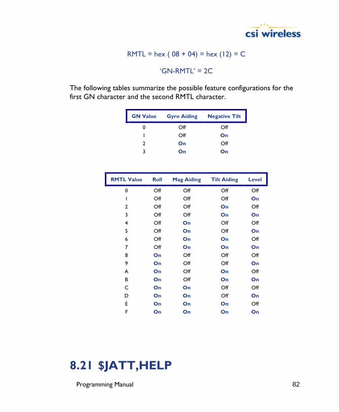
Programming Manual 82
RMTL = hex ( 08 + 04) = hex (12) = C
‘GN-RMTL’ = 2C
The following tables summarize the possible feature configurations for the first GN character and the second RMTL character.
GN Value Gyro Aiding Negative Tilt
0 Off Off
1 Off On
2 On Off
3 On On
RMTL Value Roll Mag Aiding Tilt Aiding Level
0 Off Off Off Off
1 Off Off Off On
2 Off Off On Off
3 Off Off On On
4 Off On Off Off
5 Off On Off On
6 Off On On Off
7 Off On On On
8 On Off Off Off
9 On Off Off On
A On Off On Off
B On Off On On
C On On Off Off
D On On Off On
E On On On Off
F On On On On
8.21 $JATT,HELP

Programming Manual 83
The Vector supports a command that you can use to get a short list of the supported commands if you find yourself in the field without documentation.
This command has the following format.
$JATT,HELP<CR><LF>
The response to this command will be the following.
$>JATT,HELP,CSEP,MSEP,EXACT,LEVEL,HTAU,HRTAU,HBIASPBIAS,NEGTILT,ROLL,TILTAID,TILTCAL,MAGAID,MAGCAL,MAGCLR,
GYROAID,COGTAU,SPDTAU,SEARCH,SUMMARY

Programming Manual 84
9. e-Dif Commands (for Mini MAX, PowerMAX and DGPS MAX only) This section provides information related to the NMEA messages accepted by the Mini MAX, PowerMAX and DGPS MAX’s e-Dif application.
The following table provides a brief description of the commands supported by the e-Dif application for its control and operation.
Table 9-1 e-Dif Commands
Message Description
$JRAD,1 This command is used to display the current reference position
$JRAD,1,P Store present position as reference
$JRAD,1,lat,lon,height Store entered position as reference
$JRAD,2 Use reference position as base
$JRAD,3 Use current position as base
The following subsections provide detailed information relating to the use of each command.
9.1 $JRAD,1 This command is used to display the current reference position. This command has the following format:
$JRAD,1<CR><LF>
The receiver will reply with a response similar to the following:
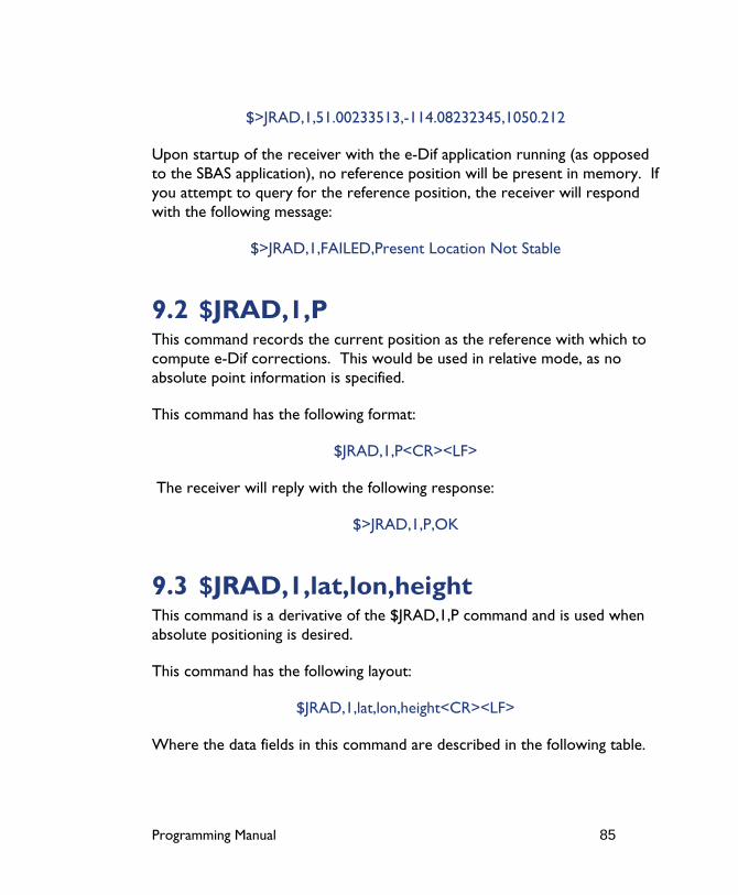
Programming Manual 85
$>JRAD,1,51.00233513,-114.08232345,1050.212
Upon startup of the receiver with the e-Dif application running (as opposed to the SBAS application), no reference position will be present in memory. If you attempt to query for the reference position, the receiver will respond with the following message:
$>JRAD,1,FAILED,Present Location Not Stable
9.2 $JRAD,1,P This command records the current position as the reference with which to compute e-Dif corrections. This would be used in relative mode, as no absolute point information is specified.
This command has the following format:
$JRAD,1,P<CR><LF>
The receiver will reply with the following response:
$>JRAD,1,P,OK
9.3 $JRAD,1,lat,lon,height This command is a derivative of the $JRAD,1,P command and is used when absolute positioning is desired.
This command has the following layout:
$JRAD,1,lat,lon,height<CR><LF>
Where the data fields in this command are described in the following table.
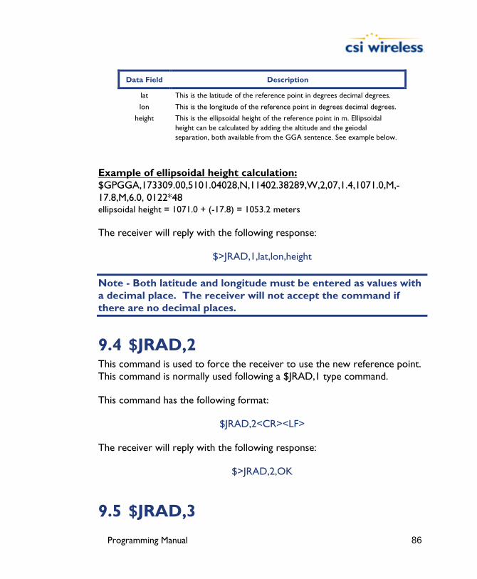
Programming Manual 86
Data Field Description
lat This is the latitude of the reference point in degrees decimal degrees.
lon This is the longitude of the reference point in degrees decimal degrees.
height This is the ellipsoidal height of the reference point in m. Ellipsoidal height can be calculated by adding the altitude and the geiodal separation, both available from the GGA sentence. See example below.
Example of ellipsoidal height calculation: $GPGGA,173309.00,5101.04028,N,11402.38289,W,2,07,1.4,1071.0,M,-17.8,M,6.0, 0122*48 ellipsoidal height = 1071.0 + (-17.8) = 1053.2 meters
The receiver will reply with the following response:
$>JRAD,1,lat,lon,height
Note - Both latitude and longitude must be entered as values with a decimal place. The receiver will not accept the command if there are no decimal places.
9.4 $JRAD,2 This command is used to force the receiver to use the new reference point. This command is normally used following a $JRAD,1 type command.
This command has the following format:
$JRAD,2<CR><LF>
The receiver will reply with the following response:
$>JRAD,2,OK
9.5 $JRAD,3

Programming Manual 87
This command is used for two primary purposes. The first is to invoke the e-Dif function once the unit has started up (with the e-Dif application active). The second purpose is to update the e-Dif solution (calibration) using the current position as opposed to the reference position used by the $JRAD,2 command.
This command has the following format:
$JRAD,3<CR><LF>
The receiver will respond with the following command if it has tracked enough satellites for a long enough period before you sent the command. This period of time can be from 3 to 10 minutes long and is used for modeling errors going forward.
$>JRAD,3,OK<CR><LF>
If the e-Dif algorithms do not find that there has been sufficient data collected, the receiver will send the following response:
$>JRAD,3,FAILED,Not Enough Stable Satellite Tracks
If you receive the failure message after a few minutes of operation, try again shortly until the ‘OK’ acknowledgement message is sent. The e-Dif application will begin operating as soon as the $JRAD,3,OK message has been sent, however, you will still need to define a reference position for e-Dif, unless relative positioning is sufficient for your needs.

Programming Manual 88
10. Binary Data The DGPS MAX, Mini MAX, PowerMAX Vector, Vector PRO, Vector Sensor, Vector Sensor PRO and Vector OEM all support a selection of binary data messages that provide improved communication port efficiency. Additionally, certain data is available only in binary format, such as raw measurement information.
Note - The binary messages described in this chapter are turned on or off using the $JBIN and $JOFF commands discussed in Chapter 3 and 4.
10.1 Binary Message Structure The Binary messages supported by the receivers are in an Intel Little Endian format for direct read in a PC environment. You can find more information on this format at the following Web site.
www.cs.umass.edu/~verts/cs32/endian.html
Each binary message begins with an 8-byte header and ends with a carriage-return line-feed pair (0x0D, 0x0A). The first four characters of the header is the ASCII sequence $BIN.
The following table provides the general binary message structure.

Programming Manual 89
Table 10-1 Binary Message Structure
Group Components Type Bytes Value
Synchronization String 4 byte string 4 $BIN
BlockID - a number which tells the type of binary message
Unsigned short
2 1, 2, 80, 93, 94, 95, 96, 97, 98, or 99
Header
DataLength - the length of the binary messages
Unsigned short
2 52, 16, 40, 56, 96, 128, 300, 28, 68, or 304
Data Binary Data - varying fields of data with a total length of DataLength bytes
Mixed fields 52, 16, 40, 56, 96, 128, 300, 28, 68, or 304
Varies - see message tables
Checksum - sum of all bytes of the data (all DataLength bytes). The sum is placed in a 2-byte integer
Unsigned short
2 Sum of data bytes
CR - Carriage return Byte 1 0D hex
Epilogue
LF - Line feed Byte 1 0A hex
The total length of the binary message packet is DataLength plus 12 (8 byte header, 2 byte checksum, and 2 bytes for CR, LF).
10.2 Bin 1 This message has a BlockID of 1 and is 52 bytes excluding the header and epilogue. It consists of GPS position and velocity data. It is the only binary message that can be output at a rate of 5 Hz. The following table describes the content of this message.
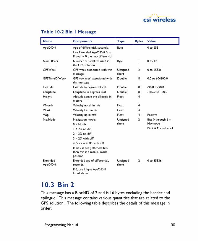
Programming Manual 90
Table 10-2 Bin 1 Message
Name Components Type Bytes Value
AgeOfDiff Age of differential, seconds.
Use Extended AgeOfDiff first. If both = 0 then no differential
Byte 1 0 to 255
NumOfSats Number of satellites used in the GPS solution
Byte 1 0 to 12
GPSWeek GPS week associated with this message
Unsigned short
2 0 to 65536
GPSTimeOfWeek GPS tow (sec) associated with this message
Double 8 0.0 to 604800.0
Latitude Latitude in degrees North Double 8 -90.0 to 90.0
Longitude Longitude in degrees East Double 8 -180.0 to 180.0
Height Altitude above the ellipsoid in meters
Float 4
VNorth Velocity north in m/s Float 4
VEast Velocity East in n/s Float 4
VUp Velocity up in m/s Float 4 Positive
NavMode Navigation mode:
0 = No fix
1 = 2D no diff
2 = 3D no diff
3 = 2D with diff
4, 5, or 6 = 3D with diff
If bit 7 is set (left-most bit), then this is a manual mark position
Unsigned short
2 Bits 0 through 6 = Navmode
Bit 7 = Manual mark
Extended AgeOfDiff
Extended age of differential, seconds.
If 0, use 1 byte AgeOfDiff listed above
Unsigned short
2 0 to 65536
10.3 Bin 2 This message has a BlockID of 2 and is 16 bytes excluding the header and epilogue. This message contains various quantities that are related to the GPS solution. The following table describes the details of this message in order.

Programming Manual 91
Table 10-3 Bin 2 Message
Name Components Type Bytes Value
MaskSatsTracked A mask of satellites tracked by the GPS. Bit 0 corresponds to the GPS satellite with PRN 1.
Unsigned long
4 Individual bits represent satellites
MaskSatsUsed A mask of satellites used in the GPS solution. Bit 0 corresponds to the GPS satellite with PRN 1.
Unsigned long
4 Individual bits represent satellites
GPSUtcDiff Whole seconds between UTC and GPS time (GPS minus UTC)
Unsigned short
2 Positive
HDOPTimes10 Horizontal dilution of precision scaled by 10 (0.1 units)
Unsigned short
2 Positive
VDOPTimes10 Vertical Dilution of precision scaled by 10 (0.1 units)
Unsigned short
2 Positive
WAAS PRN bitmask
PRN and tracked or used status masks
Unsigned short
2 See below
WAAS PRN bit mask.
Bit 00 Mask of satellites tracked by first WAAS satellite Bit 01 Mask of satellites tracked by second WAAS satellite Bit 02 Mask of satellites used by first WAAS satellite Bit 03 Mask of satellites used by second WAAS satellite Bit 04 Unused Bit 05-09 Value used to find PRN of first WAAS satellite (This value + 120 = PRN) Bit 10-14 Value used to find PRN of second WAAS satellite (This value + 120 = PRN) Bit 15 Unused
10.4 Bin 80

Programming Manual 92
This message has a BlockID of 80 and is 40 bytes excluding the header and epilogue. This message contains the WAAS message. The following table describes the constituents of this message in order.
Table 10-4 Bin 80 Message
Name Components Type Bytes Value
PRN Broadcast PRN Unsigned short 2
Spare Not used at this time Unsigned short 2 Future use
MsgSecOfWeek Seconds of week for message Unsigned long 4
WaasMsg[8] 250 bit WAAS message (RTCA DO-229). 8 unsigned longs with most significant bit received first
Unsigned long 4 x 8 = 32
10.5 Bin 93 This message has a BlockID of 93 and is 45 bytes excluding the header and epilogue. This message contains information relating to the WAAS ephemeris. The following table describes the contents of this message in order.

Programming Manual 93
Table 10-5 Bin 93 Message
Name Components Type Bytes Value
SV Satellite to which this data belongs Unsigned short 2
Spare Not used at this time Unsigned short 2 Future use
TOWSecOfWeek
Time at which this arrived
(LSB = 1 sec)
Unsigned long 4
IODE Unsigned short 2
URA Consult the ICD-GPS-200 for definition in Appendix A - Resources
Unsigned short 2
T0 Bit 0 = 1 sec Long 4
XG Bit 0 = 0.08 m Long 4
YG Bit 0 = 0.08 m Long 4
ZG Bit 0 = 0.4 m Long 4
XGDot Bit 0 = 0.000625 m/s Long 4
YXDot Bit 0 = 0.000625 m/s Long 4
ZGDot Bit 0 = 0.004 m/s Long 4
XGDotDot Bit 0 = 0.0000125 m/s2 Long 4
YGDotDot Bit 0 = 0.0000125 m/s2 Long 4
ZGDotDot Bit 0 = 0.0000625 m/s2 Long 4
Gf0 Bit 0 = 2**-31 s Unsigned short 2
Gf0Dot Bit0 = 2**-40 s/s Unsigned short 2
10.6 Bin 94 This message has a BlockID of 94 and is 96 bytes excluding the header and epilogue. This message contains ionospheric and UTC conversion parameters. The following table describes the details of this message in order.

Programming Manual 94
Table 10-6 Bin 94 Message
Name Components Type Bytes Value
a0,a1, a2,a3 AFCRL alpha parameters Double 8 x 4 = 32
b0,b1,b2,b3 AFCRL beta parameters Double 8 x 4 = 32
A0,A1 Coefficients for determining UTC time Double 8 x 2 = 16
tot Reference time for A0 and A1, second of GPS week
Unsigned long 4
wnt Current UTC reference week Unsigned short 2
wnlsf Week number when dtlsf becomes effective
Unsigned short 2
dn Day of week (1-7) when dtlsf becomes effective
Unsigned short 2
dtls Cumulative past leap Short 2
dtlsf Scheduled future leap Short 2
Spare Not used at this time Unsigned short 2 Future use
10.7 Bin 95 This message has a BlockID of 95 and is 128 bits excluding the header and epilogue. This message contains ephemeris data of all 12 channels. The following table describes the contents of this message in order.
Table 10-7 Bin 95 Message
Name Components Type Bytes Value
SV The satellite to which this data belongs Unsigned short
2
Spare1 Not used at this time Unsigned short
2 Future use
SecOfWeek Time at which this arrived (LSB = 6) Unsigned long 4
SF1words[10] Unparsed SF 1 message Unsigned long 4 x 10 = 40
SF2words[10] Unparsed SF 2 message Unsigned long 4 x 10 = 40
SF3words[10] Unparsed SF 3 message Unsigned long 4 x 10 = 40

Programming Manual 95
10.8 Bin 96 This message has a BlockID of 96 and is 300 bytes excluding the header and epilogue. This message contains phase and code data. The following table describes the constituents of this message in order.
Table 10-8 Bin 96 Message
Name Components Type Bytes Value
Spare1 Not used at this time Unsigned short 2 Future use
Week GPS week number Unsigned short 2
TOW Predicted GPS time in seconds
Double 8
UICS_TT_SNR_PRN[12] See below Unsigned long 4 x 12 = 48
UIDoppler_FL[12] See below Unsigned long 4 x 12 = 48
PseudoRange[12] Pseudoranges Double 8 x 12 = 96
Phase[12] Phase (m) L1 wave = 0.190293672798365 m
Double 8 x 12 = 96
Where.
UlCS_TT_SNR_PRN
Bits 0-7: PRN (PRN is 0 if no data) Bits 8-15: SNR value (SNR= 10.0 * log10 * (0.8192 * SNR value)) Bits 16-23: Phase Track Time in units of 1/10 second, range = 0 to 25.5 seconds
(see next word) Bits 24-31: Cycle Slip Counter (Increments by 1 every cycle slip with natural
rollover after 255)
UlDoppler_FL
Bit 0: 1 if Valid Phase, 0 otherwise Bit 1: 1 if Track Time > 25.5 seconds, 0 otherwise Bits 2-3: Unused Bits 4-31: Signed (two’s compliment) Doppler in units of m/sec x 4096. (i.e.,
LSB=1/4096), range = +/- 32768 m/sec. Computed as phase change over 1/10 sec.

Programming Manual 96
10.9 Bin 97 This message has a BlockID of 97 and is 28 bytes excluding the header and epilogue. This message contains statistics for processor utilization. The following table describes the details of this message in order.
Table 10-9 Bin 97 Message
Name Components Type Bytes Value
CPUFactor CPU utilization factor. Multiply by 450e-06 to get percentage of spare CPU that is available
Unsigned long 4 Positive
MissedSubFrame The total number of missed sub frames in the navigation message since power on
Unsigned short 2 Positive
MaxSubFramePnd Max sub frames queued Unsigned short 2 Positive
MissedAccum The total number of missed code accumulation measurements in the channel-tracking loop
Unsigned short 2 Positive
MissedMeas The total number of missed psuedorange measurements
Unsigned short 2 Positive
Spare 1 Not used at this time Unsigned long 4 Future use
Spare 2 Not used at this time Unsigned long 4 Future use
Spare 3 Not used at this time Unsigned long 4 Future use
Spare 4 Not used at this time Unsigned short 2 Future use
Spare 5 Not used at this time Unsigned short 2 Future use
10.10 Bin 98 This message has a BlockID of 98 and is 68 bytes excluding the header and epilogue. This message contains data derived from the satellite almanacs. The following table describes the contents of this message in order.
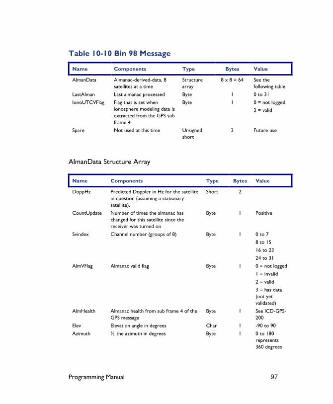
Programming Manual 97
Table 10-10 Bin 98 Message
Name Components Type Bytes Value
AlmanData Almanac-derived-data, 8 satellites at a time
Structure array
8 x 8 = 64 See the following table
LastAlman Last almanac processed Byte 1 0 to 31
IonoUTCVFlag Flag that is set when ionosphere modeling data is extracted from the GPS sub frame 4
Byte 1 0 = not logged
2 = valid
Spare Not used at this time Unsigned short
2 Future use
AlmanData Structure Array
Name Components Type Bytes Value
DoppHz Predicted Doppler in Hz for the satellite in question (assuming a stationary satellite).
Short 2
CountUpdate Number of times the almanac has changed for this satellite since the receiver was turned on
Byte 1 Positive
Svindex Channel number (groups of 8) Byte 1 0 to 7
8 to 15
16 to 23
24 to 31
AlmVFlag Almanac valid flag Byte 1 0 = not logged
1 = invalid
2 = valid
3 = has data (not yet validated)
AlmHealth Almanac health from sub frame 4 of the GPS message
Byte 1 See ICD-GPS-200
Elev Elevation angle in degrees Char 1 -90 to 90
Azimuth ½ the azimuth in degrees Byte 1 0 to 180 represents 360 degrees
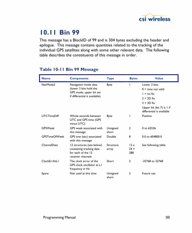
Programming Manual 98
10.11 Bin 99 This message has a BlockID of 99 and is 304 bytes excluding the header and epilogue. This message contains quantities related to the tracking of the individual GPS satellites along with some other relevant data. The following table describes the constituents of this message in order.
Table 10-11 Bin 99 Message
Name Components Type Bytes Value
NavMode2 Navigation mode data (lower 3 bits hold the GPS mode, upper bit set if differential is available).
Byte 1 Lower 3 bits:
0 = time not valid
1 = no fix
2 = 2D fix
3 = 3D fix
Upper bit (bit 7) is 1 if differential is available
UTCTimeDiff Whole seconds between UTC and GPS time (GPS minus UTC)
Byte 1 Positive
GPSWeek GPS week associated with this message
Unsigned short
2 0 to 65536
GPSTimeOfWeek GPS tow (sec) associated with this message
Double 8 0.0 to 604800.0
ChannelData 12 structures (see below) containing tracking data for each of the 12 receiver channels
Structure array
12 x 24 = 288
See following table
ClockErrAtL1 The clock error of the GPS clock oscillator at L1 frequency in Hz
Short 2 -32768 to 32768
Spare Not used at this time Unsigned short
2 Future use
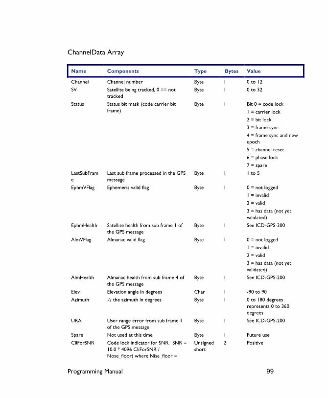
Programming Manual 99
ChannelData Array
Name Components Type Bytes Value
Channel Channel number Byte 1 0 to 12
SV Satellite being tracked, 0 == not tracked
Byte 1 0 to 32
Status Status bit mask (code carrier bit frame)
Byte 1 Bit 0 = code lock
1 = carrier lock
2 = bit lock
3 = frame sync
4 = frame sync and new epoch
5 = channel reset
6 = phase lock
7 = spare
LastSubFrame
Last sub frame processed in the GPS message
Byte 1 1 to 5
EphmVFlag Ephemeris valid flag Byte 1 0 = not logged
1 = invalid
2 = valid
3 = has data (not yet validated)
EphmHealth Satellite health from sub frame 1 of the GPS message
Byte 1 See ICD-GPS-200
AlmVFlag Almanac valid flag Byte 1 0 = not logged
1 = invalid
2 = valid
3 = has data (not yet validated)
AlmHealth Almanac health from sub frame 4 of the GPS message
Byte 1 See ICD-GPS-200
Elev Elevation angle in degrees Char 1 -90 to 90
Azimuth ½ the azimuth in degrees Byte 1 0 to 180 degrees represents 0 to 360 degrees
URA User range error from sub frame 1 of the GPS message
Byte 1 See ICD-GPS-200
Spare Not used at this time Byte 1 Future use
CliForSNR Code lock indicator for SNR. SNR = 10.0 * 4096 CliForSNR / Nose_floor) where Nise_floor =
Unsigned short
2 Positive

Programming Manual 100
80000.0
DiffCorr 100 times the differential correction for this channel’s psuedorange
Short 2
PosResid 10 times the position residual from the GPS solution for this chanel
Short 2
VelResid 10 times the velocity residual from the GPS solution for this channel
Short 2
DoppHZ Expected Doppler for this channel in Hz
Short 2
NCOHz Carrier track offset for this channel in Hz
Short 2

Programming Manual 101
11. Menu System Commands (for DGPS MAX only) The menu system is operated by a processor on-board the SLX within the DGPS MAX. The menu system responds to a selection of specific NMEA messages. In order to communicate with the processor running the menu system, a virtual connection must first be established using the $JCONN,AB command, issued through the MAIN port of the DGPS MAX.
The following table provides a brief description of the commands supported by this processor for control of the menu system setup and operation.
Table 11-1 Menu System Commands
Message Description
$PCSI,HELP Sending this command returns the available commands and queries for menu operations
$PCSI,BAUD This command allows you to change the baud rates
$PCSI,STATUS This command is not supported and is present for debugging purposes only
$PCSI,SETUP,SET You may use this command to change the menu system setup of the DGPS MAX
$PCSI,SETUP,SHOW This command is used to display the current menu system setup of the DGPS MAX
$PCSI,SETUP,SAVE Sending this command will save the current menu system setup
$PCSI,SETUP,READ This command is used to verify the integrity of the menu system setup saved in memory
$PCSI,SETUP,RESET Use this command to reset the menu system configuration
$PCSI,SETUP,INTRO This command allows you to modify the introduction screen displayed upon power-up
$PCSI,SETUP,MUX This command is not supported
The following subsections provide detailed information relating to the use of each command.

Programming Manual 102
11.1 Virtual Circuit ($JCONN,AB) The commands described in this section require the issue of the virtual circuit command, $JCONN,AB discussed in Chapter 3. This command establishes a direct connection to the microprocessor that operates the menu system of the DGPS MAX receiver.
11.2 $PCSI,HELP This command provides a listing of the available commands for use and has the following definition:
$PCSI,HELP<CR><LF>
The DGPS MAX will respond with the following data output:
$>PCSI,Version,P022-x.xxx $>PCSI,HELP -Help message $>PCSI,BAUD, -Baud Rate $>PCSI,SETUP,SET, -LL,HGT,SPD,UTC,SRC,RT $>PCSI,SETUP,SHOW -Shows Setup $>PCSI,SETUP,MUX -Enable/Disable Communication Mux $>PCSI,STATUS,CS -Checksum Error Report
Where ‘x.xxx’ is the current menu system version number.
11.3 $PCSI,BAUD The $PCSI,BAUD command is used to change the DGPS MAX’s baud rate and has the following structure:
$PCSI,BAUD,baud<CR><LF>
Where ‘baud’ is the following valid baud rates.
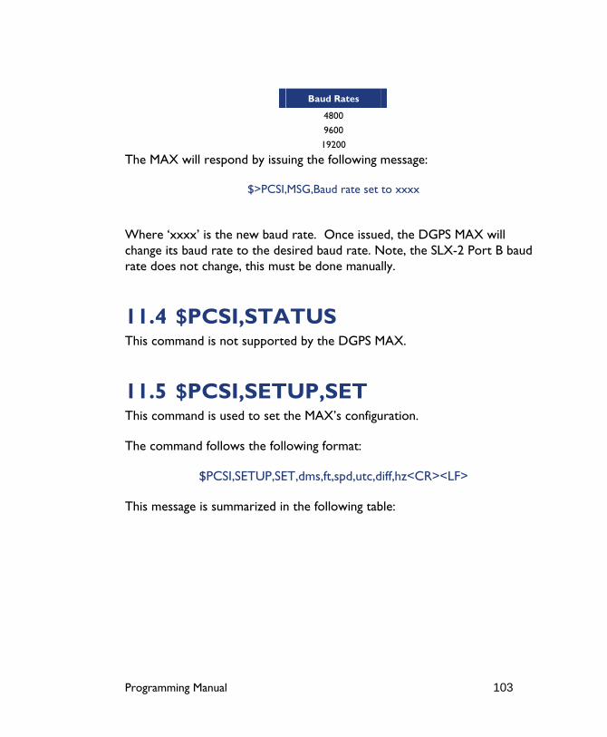
Programming Manual 103
Baud Rates
4800
9600
19200
The MAX will respond by issuing the following message:
$>PCSI,MSG,Baud rate set to xxxx
Where ‘xxxx’ is the new baud rate. Once issued, the DGPS MAX will change its baud rate to the desired baud rate. Note, the SLX-2 Port B baud rate does not change, this must be done manually.
11.4 $PCSI,STATUS This command is not supported by the DGPS MAX.
11.5 $PCSI,SETUP,SET This command is used to set the MAX’s configuration.
The command follows the following format:
$PCSI,SETUP,SET,dms,ft,spd,utc,diff,hz<CR><LF>
This message is summarized in the following table:
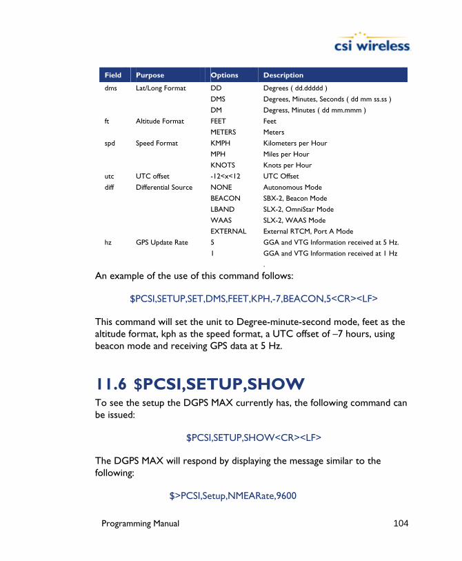
Programming Manual 104
Field Purpose Options Description
dms Lat/Long Format DD Degrees ( dd.ddddd )
DMS Degrees, Minutes, Seconds ( dd mm ss.ss )
DM Degress, Minutes ( dd mm.mmm )
ft Altitude Format FEET Feet
METERS Meters
spd Speed Format KMPH Kilometers per Hour
MPH Miles per Hour
KNOTS Knots per Hour
utc UTC offset -12<x<12 UTC Offset
diff Differential Source NONE Autonomous Mode
BEACON SBX-2, Beacon Mode
LBAND SLX-2, OmniStar Mode
WAAS SLX-2, WAAS Mode
EXTERNAL External RTCM, Port A Mode
hz GPS Update Rate 5 GGA and VTG Information received at 5 Hz.
1 GGA and VTG Information received at 1 Hz
.
An example of the use of this command follows:
$PCSI,SETUP,SET,DMS,FEET,KPH,-7,BEACON,5<CR><LF>
This command will set the unit to Degree-minute-second mode, feet as the altitude format, kph as the speed format, a UTC offset of –7 hours, using beacon mode and receiving GPS data at 5 Hz.
11.6 $PCSI,SETUP,SHOW To see the setup the DGPS MAX currently has, the following command can be issued:
$PCSI,SETUP,SHOW<CR><LF>
The DGPS MAX will respond by displaying the message similar to the following:
$>PCSI,Setup,NMEARate,9600
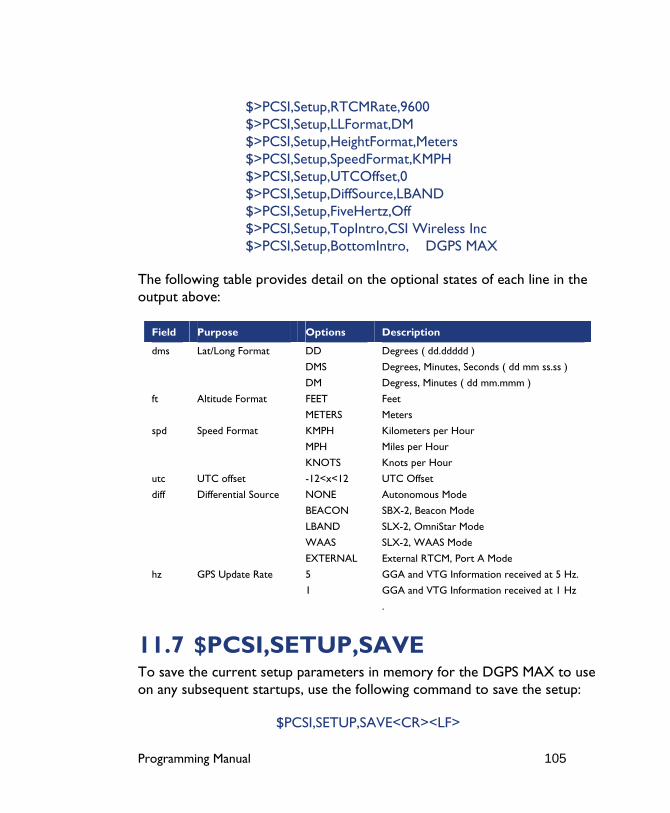
Programming Manual 105
$>PCSI,Setup,RTCMRate,9600 $>PCSI,Setup,LLFormat,DM $>PCSI,Setup,HeightFormat,Meters $>PCSI,Setup,SpeedFormat,KMPH $>PCSI,Setup,UTCOffset,0 $>PCSI,Setup,DiffSource,LBAND $>PCSI,Setup,FiveHertz,Off $>PCSI,Setup,TopIntro,CSI Wireless Inc $>PCSI,Setup,BottomIntro, DGPS MAX
The following table provides detail on the optional states of each line in the output above:
Field Purpose Options Description
dms Lat/Long Format DD Degrees ( dd.ddddd )
DMS Degrees, Minutes, Seconds ( dd mm ss.ss )
DM Degress, Minutes ( dd mm.mmm )
ft Altitude Format FEET Feet
METERS Meters
spd Speed Format KMPH Kilometers per Hour
MPH Miles per Hour
KNOTS Knots per Hour
utc UTC offset -12<x<12 UTC Offset
diff Differential Source NONE Autonomous Mode
BEACON SBX-2, Beacon Mode
LBAND SLX-2, OmniStar Mode
WAAS SLX-2, WAAS Mode
EXTERNAL External RTCM, Port A Mode
hz GPS Update Rate 5 GGA and VTG Information received at 5 Hz.
1 GGA and VTG Information received at 1 Hz
.
11.7 $PCSI,SETUP,SAVE To save the current setup parameters in memory for the DGPS MAX to use on any subsequent startups, use the following command to save the setup:
$PCSI,SETUP,SAVE<CR><LF>
Programming Manual 106
The MAX will respond by displaying the following message:
$>PCSI,SETUP,Setup Saved
11.8 $PCSI,SETUP,READ To verify the current setup parameters saved in memory, use the following command to read the setup:
$PCSI,SETUP,READ<CR><LF>
The DGPS MAX will respond by displaying the following messages. If the CRC check on the memory passed, the response would be:
$>PCSI,MSG,CRC Passed $>PCSI,SETUP,Setup Read
If the CRC check of the memory failed, the response would be:
$>PCSI,MSG,CRC Failed $>PCSI,SETUP,Setup Read
If you find that the verification fails, please contact CSI Wireless technical support for assistance.
11.9 $PCSI,SETUP,RESET To reset the current setup parameters in RAM, use the following command to reset the setup:
$PCSI,SETUP,RESET<CR><LF>
The DGPS MAX will clear the configuration in RAM, but not in FLASH and set all values to their default state.
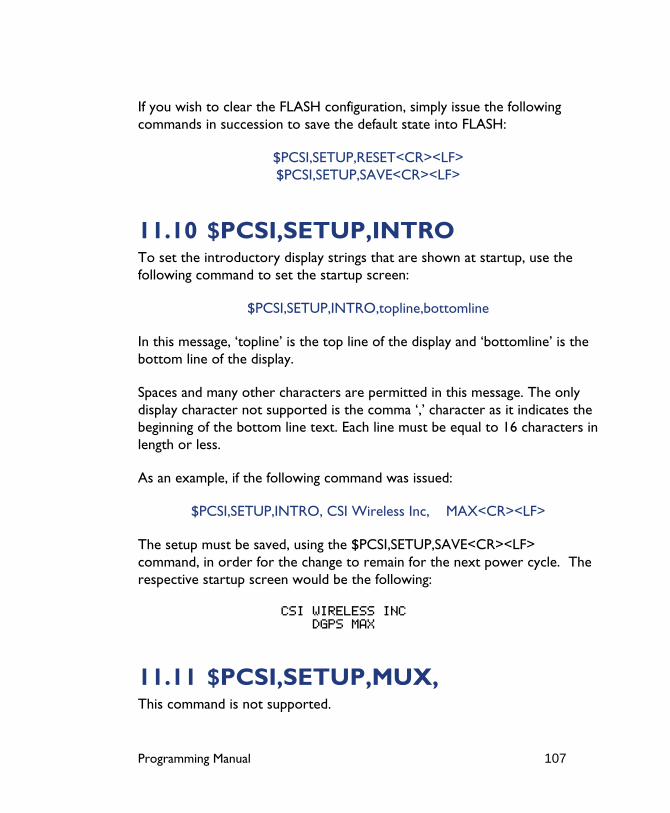
Programming Manual 107
If you wish to clear the FLASH configuration, simply issue the following commands in succession to save the default state into FLASH:
$PCSI,SETUP,RESET<CR><LF> $PCSI,SETUP,SAVE<CR><LF>
11.10 $PCSI,SETUP,INTRO To set the introductory display strings that are shown at startup, use the following command to set the startup screen:
$PCSI,SETUP,INTRO,topline,bottomline
In this message, ‘topline’ is the top line of the display and ‘bottomline’ is the bottom line of the display.
Spaces and many other characters are permitted in this message. The only display character not supported is the comma ‘,’ character as it indicates the beginning of the bottom line text. Each line must be equal to 16 characters in length or less.
As an example, if the following command was issued:
$PCSI,SETUP,INTRO, CSI Wireless Inc, MAX<CR><LF>
The setup must be saved, using the $PCSI,SETUP,SAVE<CR><LF> command, in order for the change to remain for the next power cycle. The respective startup screen would be the following:
CSI WIRELESS INC DGPS MAX
11.11 $PCSI,SETUP,MUX, This command is not supported.
Programming Manual 108
12. Configuration Wizard (for DGPS MAX only) The Configuration Wizard is a useful feature that allows you to choose pre-defined configurations for DGPS MAX operation. You may choose a user-defined profile upon start-up or may choose to enter the Configuration Wizard at any time during receiver operation. The Configuration Wizard is described in detail in Chapter 6 of the DGPS MAX Reference Manual.
There are two main parts to the Configuration Wizard: you may choose to configure the DGPS MAX easily, step-by-step, or you may choose a pre-defined profile from one of the five saved in memory. Since the DGPS MAX is shipped with no pre-defined profiles, it’s advantageous to define the configurations as you feel necessary.
Using pre-defined configurations in the field is especially advantageous when more than one DGPS MAX receiver is being used in the field by different people for different purposes. A configuration may be easily selected in the field with just a few keystrokes, customizing the DGPS MAX for the task at hand.
You may define the configurations either by using the menu system or you may use a NMEA command. Using the menu system is a convenient method of defining the profiles, however, it may be more efficient to define the profiles once in a terminal program, and then configure the Wizard through the serial port for the DGPS MAX. This is the preferred method if many DGPS MAX receivers need to be configured with the same profiles for consistency throughout a pool of receivers.
This section presents various commands relating to setup of the Configuration Wizard through the serial port. This allows you to pre-configure the Wizard configurations before the receiver goes into the field, according to your specific needs.
Programming Manual 109
For consistency from unit to unit and from time to time, we recommend that you use a terminal program that allows you to program the desired NMEA commands into soft-keys. Using soft-keys, you may send a command easily by simply pressing a button. These soft-keys and the terminal configuration may be saved so that the same profile could be used in the future without having to re-enter the NMEA commands. Contact CSI Wireless technical support if you have questions relating to a suitable terminal program.
The following table provides a brief description of the general commands supported by DGPS MAX.
Table 12-1 Configuration Wizard Commands
Message Description
$PCSI,WIZARD,SET This command is the first half of defining one of the five configurations.
$PCSI,WIZARD,RATES This command is the second half of defining one of the five configurations.
$PCSI,WIZARD,SHOW This command allows you to display the contents of the Configuration Wizard’s entries.
12.1 Virtual Circuit ($JCONN,AB) The commands described in this section require the issue of the virtual circuit command, $JCONN,AB discussed in Chapter 3. This command establishes a direct connection to the microprocessor that operates the menu system of the DGPS MAX receiver.
12.2 $PCSI,WIZARD,SET This command is used to set the Wizard parameters.
The command follows the following format:
$PCSI,WIZARD,SETUP,n,Nm,rt1,rt2,diff,el,age,lfreq,lsym,bfreq,br
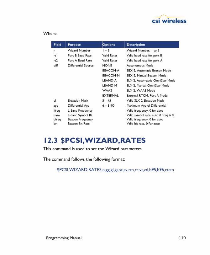
Programming Manual 110
Where:
Field Purpose Options Description
n Wizard Number 1 – 5 Wizard Number, 1 to 5
rt1 Port B Baud Rate Valid Rates Valid baud rate for port B
rt2 Port A Baud Rate Valid Rates Valid baud rate for port A
diff Differential Source NONE Autonomous Mode
BEACON-A SBX-2, Automatic Beacon Mode
BEACON-M SBX-2, Manual Beacon Mode
LBAND-A SLX-2, Automatric OmniStar Mode
LBAND-M SLX-2, Manual OmniStar Mode
WAAS SLX-2, WAAS Mode
EXTERNAL External RTCM, Port A Mode
el Elevation Mask 5 – 45 Valid SLX-2 Elevation Mask
age Differential Age 6 – 8100 Maximum Age of Differential
lfreq L-Band Frequency Valid frequency, 0 for auto lsym L-Band Symbol Rt. Valid symbol rate, auto if lfreq is 0 bfreq Beacon Frequency Valid frequency, 0 for auto br Beacon Bit Rate Valid bit rate, 0 for auto
12.3 $PCSI,WIZARD,RATES This command is used to set the Wizard parameters.
The command follows the following format:
$PCSI,WIZARD,RATES,n,gg,gl,gs,st,sv,rm,rr,vt,zd,b95,b96,rtcm
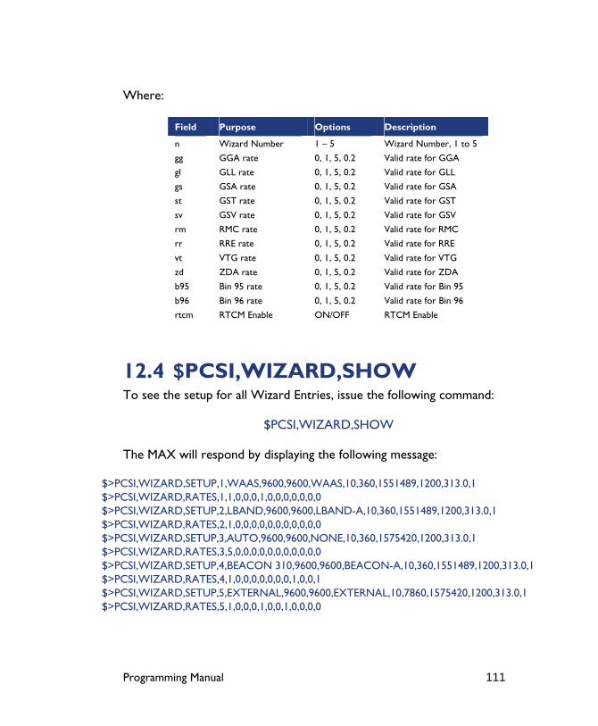
Programming Manual 111
Where:
Field Purpose Options Description
n Wizard Number 1 – 5 Wizard Number, 1 to 5
gg GGA rate 0, 1, 5, 0.2 Valid rate for GGA
gl GLL rate 0, 1, 5, 0.2 Valid rate for GLL
gs GSA rate 0, 1, 5, 0.2 Valid rate for GSA
st GST rate 0, 1, 5, 0.2 Valid rate for GST
sv GSV rate 0, 1, 5, 0.2 Valid rate for GSV
rm RMC rate 0, 1, 5, 0.2 Valid rate for RMC
rr RRE rate 0, 1, 5, 0.2 Valid rate for RRE
vt VTG rate 0, 1, 5, 0.2 Valid rate for VTG
zd ZDA rate 0, 1, 5, 0.2 Valid rate for ZDA
b95 Bin 95 rate 0, 1, 5, 0.2 Valid rate for Bin 95
b96 Bin 96 rate 0, 1, 5, 0.2 Valid rate for Bin 96
rtcm RTCM Enable ON/OFF RTCM Enable
12.4 $PCSI,WIZARD,SHOW To see the setup for all Wizard Entries, issue the following command:
$PCSI,WIZARD,SHOW
The MAX will respond by displaying the following message:
$>PCSI,WIZARD,SETUP,1,WAAS,9600,9600,WAAS,10,360,1551489,1200,313.0,1 $>PCSI,WIZARD,RATES,1,1,0,0,0,1,0,0,0,0,0,0,0 $>PCSI,WIZARD,SETUP,2,LBAND,9600,9600,LBAND-A,10,360,1551489,1200,313.0,1 $>PCSI,WIZARD,RATES,2,1,0,0,0,0,0,0,0,0,0,0,0 $>PCSI,WIZARD,SETUP,3,AUTO,9600,9600,NONE,10,360,1575420,1200,313.0,1 $>PCSI,WIZARD,RATES,3,5,0,0,0,0,0,0,0,0,0,0,0 $>PCSI,WIZARD,SETUP,4,BEACON 310,9600,9600,BEACON-A,10,360,1551489,1200,313.0,1 $>PCSI,WIZARD,RATES,4,1,0,0,0,0,0,0,0,1,0,0,1 $>PCSI,WIZARD,SETUP,5,EXTERNAL,9600,9600,EXTERNAL,10,7860,1575420,1200,313.0,1 $>PCSI,WIZARD,RATES,5,1,0,0,0,1,0,0,1,0,0,0,0

Programming Manual 112
13. Frequently Asked Questions Q - My receiver doesn’t appear to be communicating, what do I do?
A - This could be one of a few issues:
1. Examine the cables and connectors for signs of damage.
2. Ensure that you are properly powering the system with the correct voltage.
3. Since you’re required to terminate the power input with your choice of connector, ensure that you have made a good connection to the power supply.
4. Check the documentation of the receiving device, if not a PC computer to ensure that the transmit line from the receiver is connected to the receive line of the other device. Also ensure that the signal grounds are connected.
5. If the receiver is connected to a custom or special device, ensure that the serial connection to it does not have any incompatible signal lines present that may not allow either to communicate properly.
6. Make sure that the baud rate of the receiver matches the other device. The other device must also support an 8 data bit, 1 stop bit, and no parity port configuration (8-N-1). Some devices support different settings that may be user-configurable. Ensure that the settings match.
7. Consult the troubleshooting section of the other devices reference manual to determine if there may be a problem with that equipment.
Q - How can I determine the current configuration of the receiver?
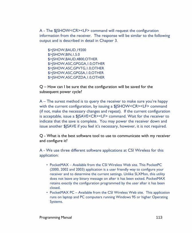
Programming Manual 113
A - The $JSHOW<CR><LF> command will request the configuration information from the receiver. The response will be similar to the following output and is described in detail in Chapter 3.
$>JSHOW,BAUD,19200 $>JSHOW,BIN,1,5.0 $>JSHOW,BAUD,4800,OTHER $>JSHOW,ASC,GPGGA,1.0,OTHER $>JSHOW,ASC,GPVTG,1.0,OTHER $>JSHOW,ASC,GPGSA,1.0,OTHER $>JSHOW,ASC,GPZDA,1.0,OTHER
Q – How can I be sure that the configuration will be saved for the subsequent power cycle?
A – The surest method is to query the receiver to make sure you’re happy with the current configuration, by issuing a $JSHOW<CR><LF> command (if not, make the necessary changes and repeat). If the current configuration is acceptable, issue a $JSAVE<CR><LF> command. Wait for the receiver to indicate that the save is complete. You may power the receiver down and issue another $JSAVE if you feel it’s necessary, however, it is not required.
Q - What is the best software tool to use to communicate with my receiver and configure it?
A - We use three different software applications at CSI Wireless for this application:
• PocketMAX – Available from the CSI Wireless Web site. This PocketPC (2000, 2002 and 2003) application is a user friendly way to configure your receiver and to determine the current settings. Unlike SLXMon, this utility does not leave any binary message on after it has been exited. PocketMAX retains exactly the configuration programmed by the user after it has been closed.
• PocketMAX PC – Available from the CSI Wireless Web site. This application runs on laptop and PC computers running Windows 95 or higher Operating Systems.
Programming Manual 114
• HyperTerminal – Available on all Windows 95, 98, ME, 2000 and XP. This tool is useful as it allows you to easily configure the receiver by directly typing commands into the terminal window. The output from the receiver is shown simultaneously. Ensure that when using HyperTerminal that it is configured to use the correct PC communication port, baud rate, and that the local echo feature is on (to see what you are typing).

Programming Manual 115
Appendix A - Resources ICD-GPS-200 Specification is available for download from the following website:
https://gpstest.46tg.af.mil/webpub/general/bbs.nsf/($All)/cb09775cdcb7eb6e8825662d0056ee92?OpenDocument
Programming Manual 116
Further Reading National Marine Electronics Association, National Marine Electronics Association (NMEA 0183) Standard for Interfacing Marine Electronic Devices, Version 2.1, October 15, NMEA 1995, PO Box 50040, Mobile Alabama, 36605 USA
CSI Wireless Inc., DGPS MAX Reference Manual, rev 00, March 2001, 4110 9th Street SE, Calgary Alberta, T2G 3C4 Canada
Programming Manual 117
Index
$ $GPCRQ,MSK, 80 $GPCRQ,MSS, 81 $GPGBS, 36 $GPGGA, 27 $GPGLL, 27 $GPGSA, 28 $GPGST, 29 $GPGSV, 29 $GPMSK, 73, 74, 75 $GPRMC, 30 $GPRRE, 31 $GPVTG, 31 $GPZDA, 32 $J4STRING, 56 $JAGE, 55 $JAIR, 39 $JALT, 41 $JAPP, 42 $JASC,D1, 39 $JASC,GP, 53 $JASC,VIRTUAL, 40 $JBAUD, 43 $JBIN, 52 $JCONN, 44 $JDIFF, 45 $JK, 45 $JOFF, 55 $JPOS, 46 $JQUERY,GUIDE, 47 $JRAD,1, 102, 103 $JRAD,1,P, 103 $JRAD,2, 104 $JRAD,3, 105 $JRAIM, 57, 59 $JRESET, 47 $JSAVE, 47 $JSHOW, 48 $JT, 50 $PCSI,0, 76
$PCSI,1, 76 $PCSI,2, 77 $PCSI,3, 78 $PCSI,4, 80
A Automatic Beacon Search (ABS), 75
C Customer Service, xv
G Global Search, 75
N NMEA 0183, 18, 19, 22 NMEA 0183 Beacon Command
Automatic Beacon Search, 75 Full Manual Tune, 73 Partial Manual Tune, 74 Wipe Search, 80
NMEA 0183 Messages, 19 NMEA 0183 Query
GBX Help, 76 Operating Status, 80 Performance Status, 81 Reserved, 76, 77
NMEA 0183 Response Performance Status, 74, 75
NMEA Data Message $GPGBS, 36 $GPGGA, 27 $GPGLL, 27 $GPGSA, 28 $GPGST, 29 $GPGSV, 29
Programming Manual 118
$GPRMC, 30 $GPRRE, 31 $GPVTG, 31 $GPZDA, 32
W www.csi-wireless.com, xvi