88-pol-002 88-inch cyclotron configuration management policy · 1 88-pol-002 88-inch cyclotron...
TRANSCRIPT

1
88-POL-002
88-INCH CYCLOTRON
CONFIGURATION MANAGEMENT POLICY
Nuclear Science Division Lawrence Berkeley National Laboratory
Revision 0 xx/xx/2016
Electronic Signature Approvals* Position Electronic Signature Date
Operations Supervisor
Research Coordinator / Building Manager
RPG Health Physicist
NSD Safety Coordinator
Program Head
*88-Inch Cyclotron policies use an electronic signature process that requires a unique login and password for each individual through the Berkeley Lab LDAP system. This unique information, along with a date/time stamp, is recorded in the Google document containing the procedure.
1.0 Configuration Management
1.1 Graded Approach for Configuration Management (CM)
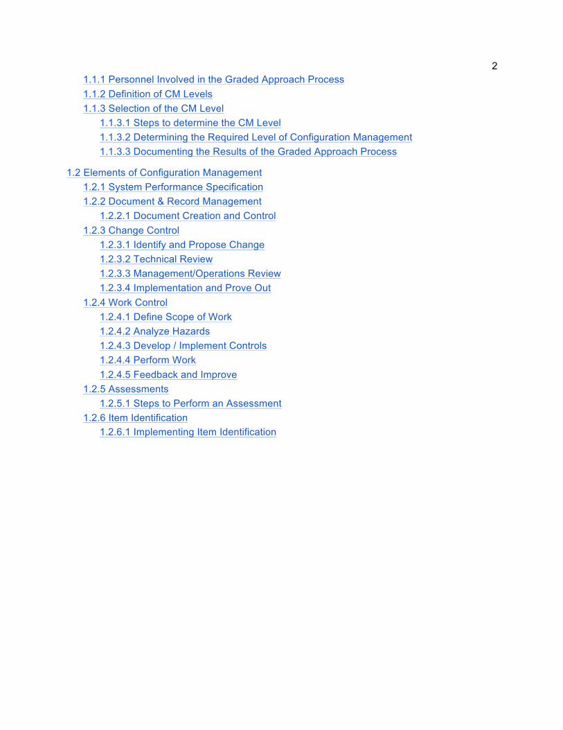
2 1.1.1 Personnel Involved in the Graded Approach Process 1.1.2 Definition of CM Levels 1.1.3 Selection of the CM Level
1.1.3.1 Steps to determine the CM Level 1.1.3.2 Determining the Required Level of Configuration Management 1.1.3.3 Documenting the Results of the Graded Approach Process
1.2 Elements of Configuration Management 1.2.1 System Performance Specification 1.2.2 Document & Record Management
1.2.2.1 Document Creation and Control 1.2.3 Change Control
1.2.3.1 Identify and Propose Change 1.2.3.2 Technical Review 1.2.3.3 Management/Operations Review 1.2.3.4 Implementation and Prove Out
1.2.4 Work Control 1.2.4.1 Define Scope of Work 1.2.4.2 Analyze Hazards 1.2.4.3 Develop / Implement Controls 1.2.4.4 Perform Work 1.2.4.5 Feedback and Improve
1.2.5 Assessments 1.2.5.1 Steps to Perform an Assessment
1.2.6 Item Identification 1.2.6.1 Implementing Item Identification
3
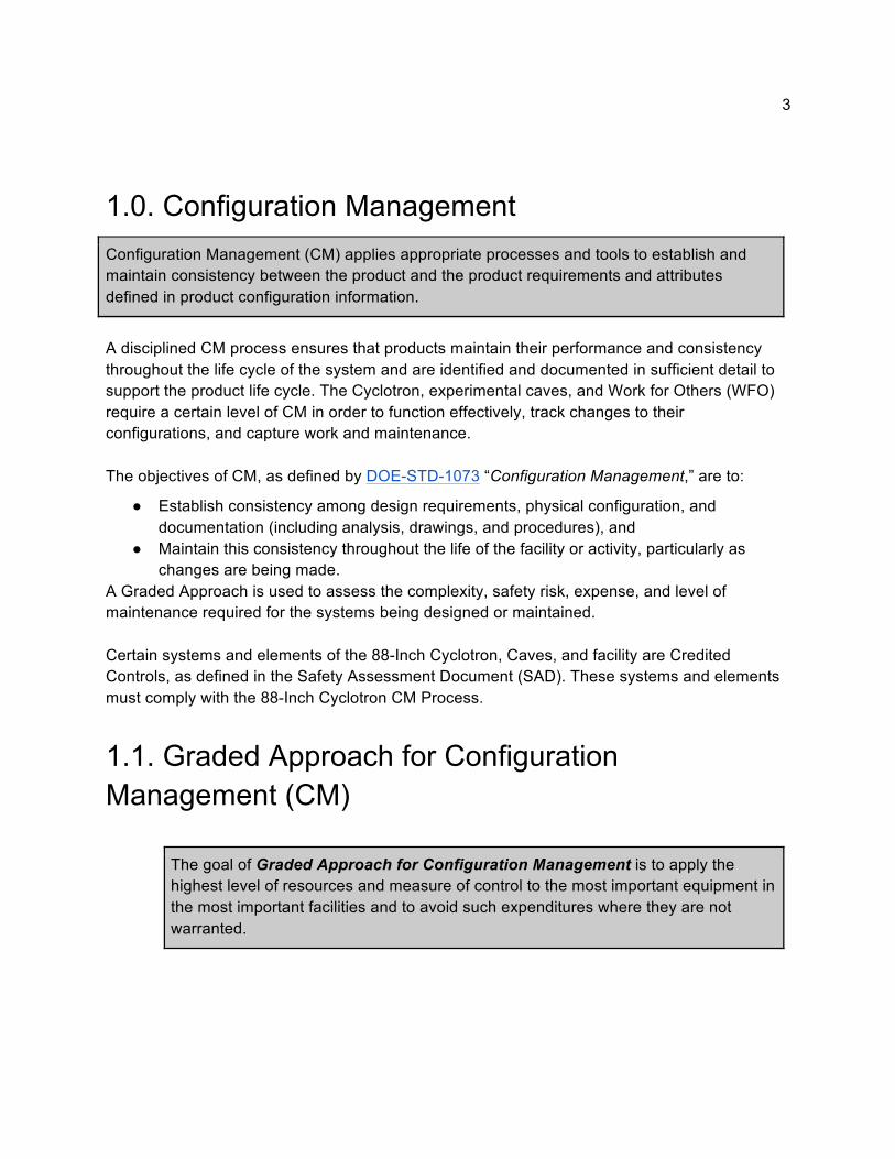
1.0. Configuration Management Configuration Management (CM) applies appropriate processes and tools to establish and maintain consistency between the product and the product requirements and attributes defined in product configuration information.
A disciplined CM process ensures that products maintain their performance and consistency throughout the life cycle of the system and are identified and documented in sufficient detail to support the product life cycle. The Cyclotron, experimental caves, and Work for Others (WFO) require a certain level of CM in order to function effectively, track changes to their configurations, and capture work and maintenance. The objectives of CM, as defined by DOE-STD-1073 “Configuration Management,” are to:
● Establish consistency among design requirements, physical configuration, and documentation (including analysis, drawings, and procedures), and
● Maintain this consistency throughout the life of the facility or activity, particularly as changes are being made.
A Graded Approach is used to assess the complexity, safety risk, expense, and level of maintenance required for the systems being designed or maintained. Certain systems and elements of the 88-Inch Cyclotron, Caves, and facility are Credited Controls, as defined in the Safety Assessment Document (SAD). These systems and elements must comply with the 88-Inch Cyclotron CM Process.
1.1. Graded Approach for Configuration Management (CM)
The goal of Graded Approach for Configuration Management is to apply the highest level of resources and measure of control to the most important equipment in the most important facilities and to avoid such expenditures where they are not warranted.

4 The purpose of utilizing a Graded Approach as part of the CM Program is to determine the appropriate level of analysis, management controls, documentation, and necessary actions commensurate for a Structure’s, System’s, or Component’s potential to:
● Create an environmental, safety, or health hazard; ● Incur a monetary loss due to damage, or to repair/rework; ● Reduce the availability of a facility or equipment; ● Adversely affect the program objective or degrade data quality; ● Unfavorably impact the public's perception of the LBNL/DOE mission.
The Graded Approach procedure is part of the lab’s CM Program and guides the user in determining the quality controls and documentation suitable for managing a Structure, System, or Component (SSC). All SSCs need to be assessed to determine the appropriate level of CM to be applied.
1.1.1. Personnel Involved in the Graded Approach Process System Owner – is responsible for ensuring that their SSC is assessed, using the prescribed graded approach to determine the appropriate level of CM to be applied. Once the CM level is defined, the System Owner must ensure that required documentation is available and that necessary actions for performing work and controlling changes are followed. The Design Authority may also be the System Owner.
Design Authority – is responsible for presenting the risks and system impacts of the SSC in performing its function. The System Owner may also be the Design Authority.
Participant – Cyclotron Operations, Engineering, Division Safety Coordinator (DSC), EHS, RPG, and Facilities should be involved in the assessment of each SSC in determining the appropriate level of CM.
1.1.2. Definition of CM Levels Table 2 “System Performance Specification” contains detail of the types of documentation and change control requirements for the different CM Levels. It is recommended that this information be collected in a single document, the System Performance Specification, with references to all the source documents (document number, title, location).
The five CM Levels are:
● Level 4 CM System - Credited control from the ASE ● Level 3 CM System - Critical to mission/operation, high safety impact,
operational and maintenance information at hand. ● Level 2 CM System - Highly impactful to mission/operation, not a critical
safety component, operational and maintenance information available.
5 ● Level 1 CM System - Contributes to mission/operation, not tied to safety,
operational and maintenance information is in basic drawings/schematics (may have to rely on availability of system expert).
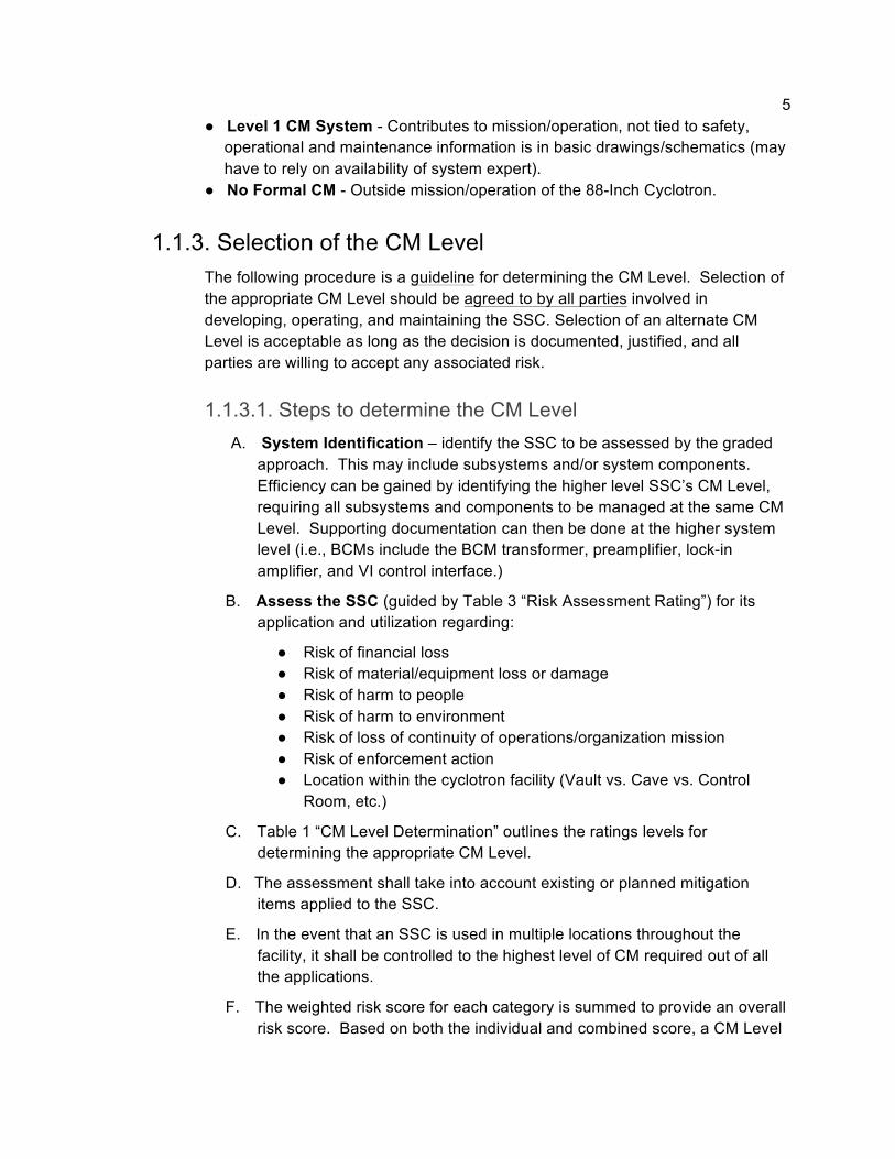
● No Formal CM - Outside mission/operation of the 88-Inch Cyclotron.
1.1.3. Selection of the CM Level The following procedure is a guideline for determining the CM Level. Selection of the appropriate CM Level should be agreed to by all parties involved in developing, operating, and maintaining the SSC. Selection of an alternate CM Level is acceptable as long as the decision is documented, justified, and all parties are willing to accept any associated risk.
1.1.3.1. Steps to determine the CM Level A. System Identification – identify the SSC to be assessed by the graded
approach. This may include subsystems and/or system components. Efficiency can be gained by identifying the higher level SSC’s CM Level, requiring all subsystems and components to be managed at the same CM Level. Supporting documentation can then be done at the higher system level (i.e., BCMs include the BCM transformer, preamplifier, lock-in amplifier, and VI control interface.)
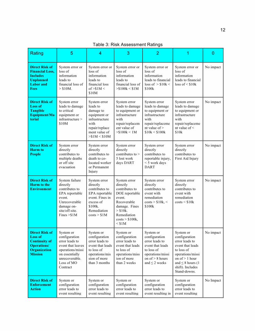
B. Assess the SSC (guided by Table 3 “Risk Assessment Rating”) for its application and utilization regarding:
● Risk of financial loss ● Risk of material/equipment loss or damage ● Risk of harm to people ● Risk of harm to environment ● Risk of loss of continuity of operations/organization mission ● Risk of enforcement action ● Location within the cyclotron facility (Vault vs. Cave vs. Control
Room, etc.)
C. Table 1 “CM Level Determination” outlines the ratings levels for determining the appropriate CM Level.
D. The assessment shall take into account existing or planned mitigation items applied to the SSC.
E. In the event that an SSC is used in multiple locations throughout the facility, it shall be controlled to the highest level of CM required out of all the applications.
F. The weighted risk score for each category is summed to provide an overall risk score. Based on both the individual and combined score, a CM Level
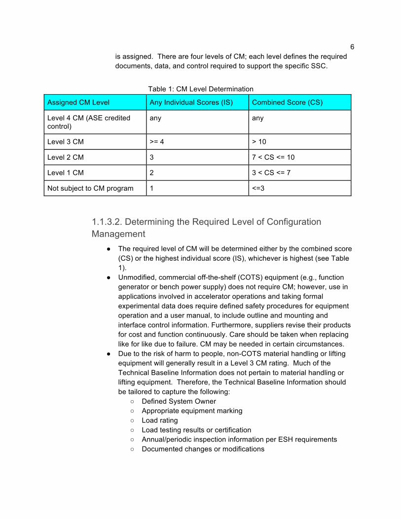
6 is assigned. There are four levels of CM; each level defines the required documents, data, and control required to support the specific SSC.
Table 1: CM Level Determination
Assigned CM Level Any Individual Scores (IS) Combined Score (CS)
Level 4 CM (ASE credited control)
any any
Level 3 CM >= 4 > 10
Level 2 CM 3 7 < CS <= 10
Level 1 CM 2 3 < CS <= 7
Not subject to CM program 1 <=3
1.1.3.2. Determining the Required Level of Configuration Management
● The required level of CM will be determined either by the combined score (CS) or the highest individual score (IS), whichever is highest (see Table 1).
● Unmodified, commercial off-the-shelf (COTS) equipment (e.g., function generator or bench power supply) does not require CM; however, use in applications involved in accelerator operations and taking formal experimental data does require defined safety procedures for equipment operation and a user manual, to include outline and mounting and interface control information. Furthermore, suppliers revise their products for cost and function continuously. Care should be taken when replacing like for like due to failure. CM may be needed in certain circumstances.
● Due to the risk of harm to people, non-COTS material handling or lifting equipment will generally result in a Level 3 CM rating. Much of the Technical Baseline Information does not pertain to material handling or lifting equipment. Therefore, the Technical Baseline Information should be tailored to capture the following:
○ Defined System Owner ○ Appropriate equipment marking ○ Load rating ○ Load testing results or certification ○ Annual/periodic inspection information per ESH requirements ○ Documented changes or modifications
7 ○ If the equipment is a custom below-the-hook device,
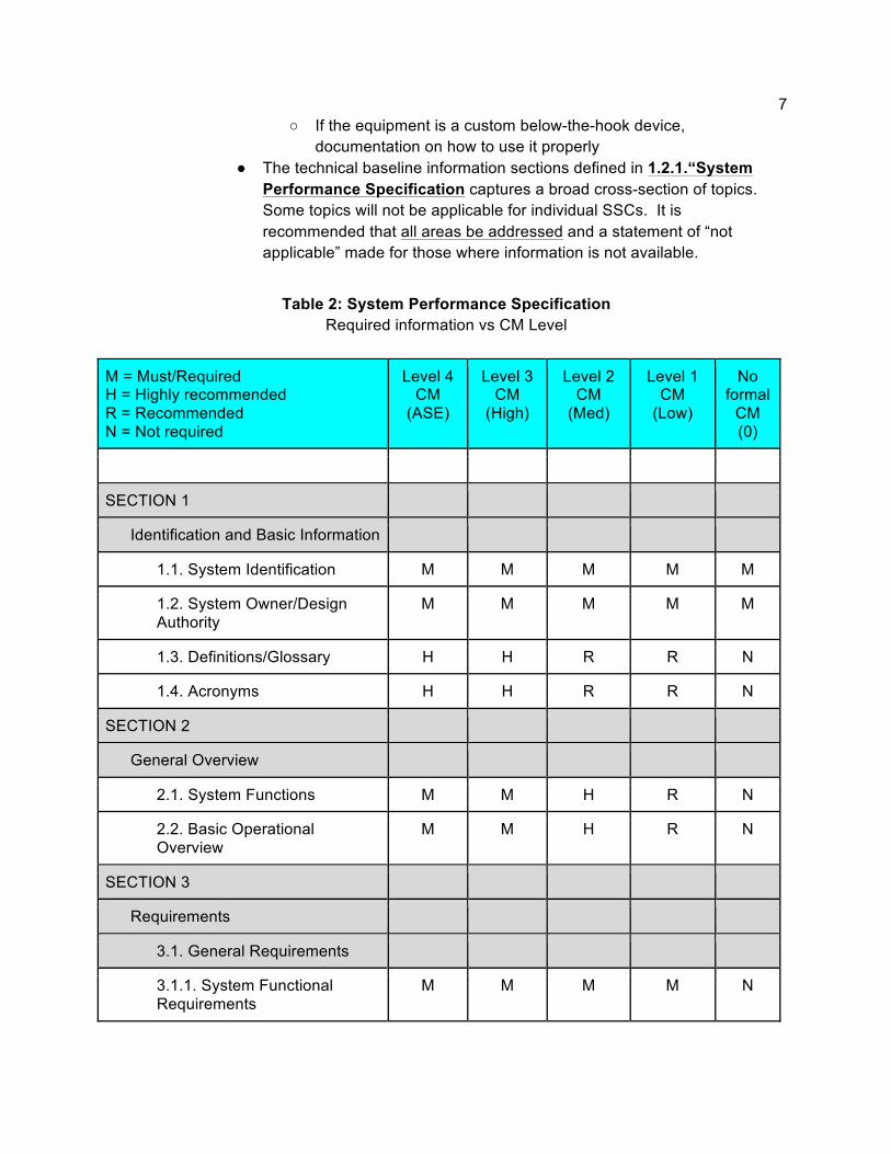
documentation on how to use it properly ● The technical baseline information sections defined in 1.2.1.“System
Performance Specification captures a broad cross-section of topics. Some topics will not be applicable for individual SSCs. It is recommended that all areas be addressed and a statement of “not applicable” made for those where information is not available.
Table 2: System Performance Specification Required information vs CM Level
M = Must/Required H = Highly recommended R = Recommended N = Not required
Level 4 CM
(ASE)
Level 3 CM
(High)
Level 2 CM
(Med)
Level 1 CM
(Low)
No formal
CM (0)
SECTION 1
Identification and Basic Information
1.1. System Identification M M M M M
1.2. System Owner/Design Authority
M M M M M
1.3. Definitions/Glossary H H R R N
1.4. Acronyms H H R R N
SECTION 2
General Overview
2.1. System Functions M M H R N
2.2. Basic Operational Overview
M M H R N
SECTION 3
Requirements
3.1. General Requirements
3.1.1. System Functional Requirements
M M M M N

8
3.1.2. Subsystems and Major Components
M M M H N
3.1.3. Boundaries and Interfaces
M M M R N
3.1.4. Codes, Standards and Regulations
M M H N N
3.1.5. Operability M M H R N
3.2. Special Requirements
3.2.1. Radiation and Other Hazards
M M M H N
3.2.2. ALARA M M M H N
3.2.3. Industrial Hazards M M M H N
3.2.4. Operating Environment and Natural Phenomenon
M M M R N
3.2.5. Human Interface Requirements
M M M R N
3.3. Engineering Disciplinary Requirements
3.3.1. Civil and Structural M M M R N
3.3.2. Mechanical and Materials
M M M M N
3.3.3. Chemical and Process M M M H N
3.3.4. Electrical Power M M M M N
3.3.5. Instrumentation and Control
M M M M N
3.3.6. Computer Hardware and Software
M M M M N
3.3.7. Fire Protection M M M R N
3.4. Testing and Maintenance Requirements
3.4.1. Inspections M M H R N
3.4.2. Testing (Plans and M M H R N

9
Records)
3.4.3. Maintenance M M H R N
3.5. Other Requirements
3.5.1. Special Installation Requirements
M M H R N
3.5.2. Reliability, Availability, and Preferred Failure Modes
M M H R N
3.5.3. Quality Assurance M M H R N
3.5.4. Miscellaneous M M R R N
SECTION 4
System Description and Additional Functionality
4.1. Configuration Information
4.1.1. Description of System, Subsystems, and Major Components
M M H R N
4.1.2. Boundaries and Interfaces
M M H H N
4.1.3. Physical Location and Layout
M M H H N
4.1.4. Principles of Operation M M H R N
4.1.5. System Reliability Features
M M H R N
4.1.6. System Control Features M M M R N
4.2. Operations
4.2.1. Initial Configuration (Pre-startup)
M M M R N
4.2.2. System Startup M M M R N
4.2.3. Normal Operations M M M R N
4.2.4. Off-Normal Operations M M M R N
4.2.5. System Shutdown M M M R N
10
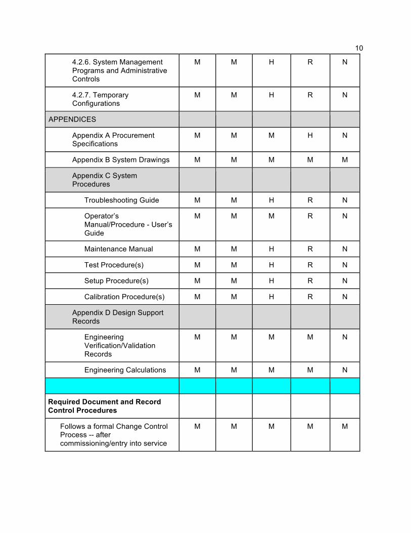
4.2.6. System Management Programs and Administrative Controls
M M H R N
4.2.7. Temporary Configurations
M M H R N
APPENDICES
Appendix A Procurement Specifications
M M M H N
Appendix B System Drawings M M M M M
Appendix C System Procedures
Troubleshooting Guide M M H R N
Operator’s Manual/Procedure - User’s Guide
M M M R N
Maintenance Manual M M H R N
Test Procedure(s) M M H R N
Setup Procedure(s) M M H R N
Calibration Procedure(s) M M H R N
Appendix D Design Support Records
Engineering Verification/Validation Records
M M M M N
Engineering Calculations M M M M N
Required Document and Record Control Procedures
Follows a formal Change Control Process -- after commissioning/entry into service
M M M M M

11 1.1.3.3. Documenting the Results of the Graded Approach Process A log shall be maintained of all SSCs, existing and new, with a record of the System Name, assembly number, CM Level, System Owner (and an Alternate), and Design Authority. The owner of the System Log is the CM Manager, the Cyclotron Operations Supervisor.
12
Table 3: Risk Assessment Ratings
Rating 5 4 3 2 1 0
Direct Risk of Financial Loss, Includes Unplanned Labor and Fees
System error or loss of information leads to financial loss of > $10M.
System error or loss of information leads to financial loss of >$1M < $10M
System error or loss of information leads to financial loss of >$100k < $1M
System error or loss of information leads to financial loss of > $10k < $100k
System error or loss of information leads to financial loss of < $10k
No impact
Direct Risk of Loss of Tangible Equipment/Material
System error leads to damage to critical equipment or infrastructure > $10M
System error leads to damage to equipment or infrastructure with repair/replacement value of >$1M < $10M
System error leads to damage to equipment or infrastructure with repair/replacement value of >$100k < 1M
System error leads to damage to equipment or infrastructure with repair/replacement value of > $10k < $100k
System error leads to damage to equipment or infrastructure with repair/replacement value of < $10k
No impact
Direct Risk of Harm to People
System error directly contributes to multiple deaths or off site evacuation
System error directly contributes to death to co-located worker or Permanent Injury
System error directly contributes to > 5 lost work days DART
System error directly contributes to reportable injury, < 5 work days DART
System error directly contributes to First Aid Injury
No impact
Direct Risk of Harm to the Environment
System failure directly contributes to EPA reportable event. Unrecoverable damage on-site/off-site. Fines >$1M
System error directly contributes to EPA reportable event. Fines in excess of $100k. Remediation costs > $1M
System error directly contributes to DOE reportable event. Recoverable damage. Fines > $10k. Remediation costs > $100k, < $1M
System error directly contributes to event with remediation costs > $10k, < $100k
System error directly contributes to event with remediation costs < $10k
No impact
Direct Risk of Loss of Continuity of Operations/ Organization Mission
System or configuration error leads to event that leaves operations/mission essentially unrecoverable. Loss of MO Contract
System or configuration error leads to event that leads to loss of operations/mission of more than 3 months
System or configuration error leads to event that leads to loss of operations/mission of more than 2 weeks
System or configuration error leads to event that leads to loss of operations/mission of > 8 hours and ≤ 2 weeks
System or configuration error leads to event that leads to loss of operations/mission of > 1 hour and ≤ 8 hours (1 shift). Includes Stand-downs.
No impact
Direct Risk of Enforcement Action
System or configuration error leads to event resulting
System or configuration error leads to event resulting
System or configuration error leads to event resulting
System or configuration error leads to event resulting in
System or configuration error leads to event resulting
No Impact
13
in Type A investigation. Lead to fines > $1M
in Type B Investigation. Operations shut down. Operations requires DOE HQ approval. Fines in excess of $100k
in OS Investigation. Fines > $1k, < $ 100k.
DOE Reportable Event. Internal Investigation
in Notable Event report
Location Accelerator - including beamline components up to exit of the Vault.
Caves Locations or systems not mentioned above.
1.2. Elements of Configuration Management Configuration Management is accomplished through the key elements of:
● System Performance Specification (SPS) ● Document Control ● Change Control ● Work Control ● Assessments ● Item Identification
1.2.1. System Performance Specification
The purpose of the System Performance Specification (SPS) is to document the design performance for a given system. Not only will it capture the Design Requirements, but the actual tested performance limits, installation, operation, interface, and maintenance of the system as well.
The SPS is one of the key building blocks of a sound Configuration Management Program. It consists of a conglomeration of documents that are the result of a complete and thorough Product Realization Process, and the requirements and specifications to which the system is to perform. The SPS shall document the physical attributes, performance measures, environmental conditions, and methods for validation and verification.
14 An SPS template that can be tailored for the specific system is available that identifies all appropriate sections. It is recommended that the document reference the documents that include the applicable information (rather than duplicating information). The form should include the following:
● Document Number, Revision, Title, Author, Reviewer and Approver ● System Identification ● System Owner / Design Authority ● System Functions ● Basic Operational Overview ● General Requirements ● Special Requirements ● Engineering Disciplinary Requirements ● Testing and Maintenance Requirements ● Other Requirements ● Additional Functionality Beyond the Requirements ● Configuration Information ● Operations Information ● Procurement Specifications ● System Drawings ● System Procedures ● Engineering Verification/Validation Records ● Engineering Calculations
1.2.2. Document & Record Management Document and Record Management serves to capture the pertinent information and data associated with the Product Realization Process. This information and data serves many purposes throughout the cyclotron facility, from capturing performance needs from the scientists, to fabrication and construction of equipment, to verification and validation to Configuration Management. Documents and records perform two specifically different functions within the lifecycle of products and systems.
Documents are living things. The information contained within them is subject to change and can be revised. They instruct their readers on what must be done and/or how to do it.
Records are a statement of history. The information contained in them is not subject to change and they should not be revised. They tell their readers what has been done.
15 Proper creation, maintenance, change control, and archiving of documents and records significantly affect the efficiency of all aspects of The 88-Inch Cyclotron Facility. Accuracy and quality are of utmost importance and should be at the forefront of consideration when dealing with documents and records. The documents and records that define the design of the system and demonstrate compliance to the Design Requirements and shall be controlled and maintained in such a manner so as to be unique in their identification, accessible at the point of use, protected from unauthorized modification, and be clearly legible.
1.2.2.1. Document Creation and Control
All official 88-Inch Cyclotron documents are governed by the procedure 88-ADM-PRO-001, Document Control.
While there is flexibility in several areas of 88-Inch Cyclotron documents and procedures, certain aspects (listed below) must be consistently followed. Fundamental Elements of Documents and Change Control
● Uniquely identify documents ● Approve their correctness and adequacy for use ● Request and approve changes ● Communicate changes ● Ensure the latest version is being used ● Provide ready access to all who need it ● Create documents which stand alone without supporting explanation ● Are prepared in accordance with LBNL and industry standards ● Are maintained in a manner which retains their legibility and ability to be retrieved. ● Document source data integrity is maintained

16
1.2.3. Change Control
Change Control for Configuration Management (CM) shall focus solely on items which are under configuration control and are already installed and commissioned in the Cyclotron, Ion Sources, or Experimental Areas.
Change Control is another of the key building blocks of a sound CM Program. The purpose of Change Control at the 88-Inch Cyclotron is to ensure that a thorough method of proposing, reviewing, and implementing changes to systems is followed. The result will be changes which have been assessed for their impact on safety and do not interfere with the successful and reliable operation of the Cyclotron, Ion Sources, or Experimental Areas. Historically, change to Cyclotron systems has been at the discretion of the system’s System Owner. The CM Process spells out different categories and their required level of Change Control and approval prior to implementation. Each System Owner shall understand the required level of Change Control applicable to their system. The Change Control process is defined in Figure 2 “Change Control Process” below. It is broken down into four sections:
● Identification and Proposal ● Technical Review ● Management/Operations Review (including USI [Unreviewed Safety Issue] review) ● Implementation and Prove Out
EXCEPTION: Items which are still under development, prototypes, or being fabricated shall not be governed by this section.
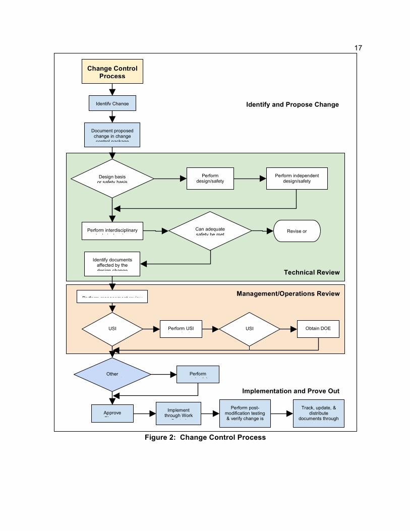
17
Figure 2: Change Control Process
Management/Operations Review
Technical Review
Change Control Process
Identify Change
Document proposed change in change control package
Design basis or safety basis
Perform
design/safety analysis
Perform independent design/safety
verification for change
Perform interdisciplinary technical review
Can adequate safety be met
Revise or cancel change
Identify documents affected by the design change
Perform management review
USI review
Perform USI determination
USI review
Obtain DOE
approval
Other reviews to be
Perform review(s)
Approve Change
Implement through Work
Control
Perform post- modification testing & verify change is
acceptable
Track, update, & distribute
documents through document control
yes
yes
yes yes
yes
no
no
no no
no Implementation and Prove Out
Identify and Propose Change
18 1.2.3.1. Identify and Propose Change
A Cyclotron Change Order (CCO) shall be used to initiate requests for changes to existing Configuration Items. The CCO process is described in 88-POL-001 88-Inch Cyclotron Configuration Control Policy for the six credited controls of the ASE.
Change Control is owned by the system’s System Owner but requires approval from those responsible for the operation of the Configuration Item. If a change is proposed for a commissioned system, follow the procedure defined below. A change control package shall be assembled which captures all pertinent documents associated with the requested change. Examples are Design Requirements Documents, Engineering Drawings, Manuals, Test Plans, Updated Engineering Calculations, etc.
1.2.3.2. Technical Review
The System Owner for the system or component is responsible for ensuring that an adequate technical review is performed.
A graded approach shall be used, based upon the magnitude and potential impact of the proposed change. Appropriate subject matter experts shall participate in the review.
● Consideration shall be given to the potential impacts on Personnel Safety and Machine Protection Systems, Credited Controls, and Defense in Depth Controls (per the SAD). Changes affecting these items require a Technical Safety review and EHS concurrence.
1.2.3.3. Management/Operations Review
A Management Review shall be performed to determine the value of implementing the change, the impact to the existing system configuration, effectivity, and timing of implementing the change, and overall approval.
An appropriate USI may be performed as part of the approval process.
19
1.2.3.4. Implementation and Prove Out
If not yet done, initiate Work Control per Section 1.2.4. Complete updates of all documentation in accordance with 88-ADM-PRO-001.
Additional reviews may be required, dependent upon results of the Management / Operations and USI reviews.
1.2.4. Work Control
The purpose of Work Control at the 88-Inch Cyclotron is to ensure that work done on configured systems is approved, does not introduce any safety risks, maintains current levels of safety for credited controls, ensures the work has been performed correctly, and verifies post-work performance to established levels.
LBNL takes a comprehensive institutional approach to its Integrated Safety Management System (ISMS), and Laboratory policy requires all work be performed safely with full regard to the well-being of workers, affiliates, the public, and the environment. Work, in the sense of Configuration Management, is an activity that physically changes or impacts the existing configuration of the system or assembly to which it is applied. Work is to be performed in accordance with PUB-3140, Integrated Environment, Safety, & Health Management Plan, and EH&S PUB-3000, Chapter 6 - Work Planning and Control, and shall meet the requirements outlined in this section. All work performed at the 88-Inch Cyclotron must be identified and captured within one of the work initiation sources: the Lab’s Work Planning & Control (WPC), A Facilities Division Work Request, an 88 Shop Request (at cyclotron.lbl.gov), or through regular planned operations maintenance. The configuration of the accelerator, Total Exclusion Areas (TEAs), and site are critical to their performance. Therefore, work done on these systems must be evaluated, scheduled, implemented, and validated in a controlled fashion. The Integrated Safety Management (ISM) process steps for Work Control at The 88-Inch Cyclotron are as follows.
20
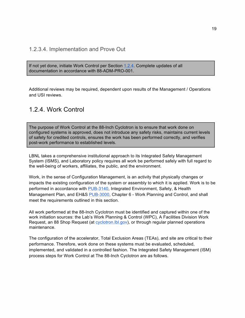
Figure 3: ISM Work Control Process
1.2.4.1. Define Scope of Work To determine the scope of work, the technical objectives are stated, the work elements to be performed are defined, the location of the work is identified, and responsible individuals overseeing the work are listed. The management chain that results from these determinations is responsible for ensuring the work activity is properly analyzed, controlled, performed, and monitored.
1.2.4.2. Analyze Hazards The authorizing organization is responsible for ensuring that the associated hazards and environmental impacts are identified. EH&S professionals are to be used in the hazard- and environmental-impact-identification process, as appropriate. Workers are to be provided an opportunity to participate in the process of identifying hazards and environmental impacts. Hazards and environmental impacts are to be identified and analyzed consistent with EH&S standards and procedures. Each individual is responsible for making conscious considerations of the implications of their actions, whether or not formal hazards analysis, identification of environmental impacts, and documentation are required.
21
1.2.4.3. Develop / Implement Controls The individual supervising the work activity is responsible for ensuring that tailored controls are developed for each hazard associated with the work activity and to reduce the impacts of significant environmental aspects. As appropriate, Subject Matter Experts (SME) are to be used in the development of work and environmental controls. Workers are strongly encouraged to be actively involved in the development of operating procedures specific to their work activities. The authorizing organization is responsible for approving the work and environmental controls and ensuring that appropriate and graded use of quality assurance principles and processes as described in the Operating and Quality Management Plan (OQMP, PUB- 3111) are incorporated and used. The designated controls are to be clearly communicated to all associated with the activity, and whose work proximity makes it prudent that they are aware of the controls. The authorizing organization and the individual supervising the work are responsible for periodically reviewing and ensuring the adequacy of the controls associated with the work activity and the effectiveness of the engineered and administrative controls incorporated.
1.2.4.4. Perform Work Work must be negotiated with the Operations Supervisor, Building Manager, Research Coordinator, etc. to establish the date and time that the work will be performed. Many areas within the facility have limited access for work performance, especially when the beam is present. Each individual is responsible for adhering to the controls established for the work activity and informing the supervisors when controls are believed to be inadequate. The line manager is responsible for ensuring that workers understand the controls and understand that work is to be performed according to the defined work controls. The individual supervising the work is responsible for ensuring that each worker has immediate access to the work activity’s governing procedures and documents. Steps shall be taken by the individual supervising the work to ensure that each worker on the activity is knowledgeable concerning the governing procedures and work and environmental controls. All work is to be performed in conformance with work instructions, including signs, work authorizations, workers’ aids, and other governing documents. If the work instructions cannot be followed safely as presented, or if they present a new hazard, the employee is responsible for notifying the appropriate individuals and assisting, as appropriate, in modifying the work instructions.
22 Each worker is empowered to stop work if there is an unsafe or unapproved condition. Prompt notification of the immediate supervisor is required. Resumption of work will not proceed until after the condition has been evaluated and the appropriate remedial actions have been taken.
1.2.4.5. Feedback and Improve Documenting and communication of work progress, issues encountered, etc. shall follow the guidelines of the organization or group for which the work is being performed. Discrepancies may be captured via redline markups of the existing documentation. The System Owner shall ensure that affected documents are updated. Once the assigned work has been performed, the system (and peripheral systems, if applicable) must be validated and verified that it works as designed. This part of the process may be performed by different members of the operations staff, but the System Owner is responsible for making certain that it is completed. Validate – ensure that the resulting product or system is capable of fulfilling the requirements for the specified or known intended use or application. Verify – ensure that the design and development outputs have satisfied the design and development input requirements.
1.2.5. Assessments
The purpose of Assessments is to ensure that the “as-built” and “as-functioning” conditions meet the design and requirements documents.
Assessments are performed at various points in the lifecycle of each system. Common types of assessments are:
Construction assessments: Performed to ensure configuration is managed throughout the construction process for new construction or major modifications.
Physical configuration assessments: Conducted to evaluate the consistency between the physical configuration and the facility documentation.
Design assessments: Ensure that design documents have been updated to reflect changes and accurately reflect the physical configuration of the system or facility. In general, these are performed as walkdowns prior to performing work on a system. They are also used as a means to verify existing conditions prior to creation of a new design.
23 Post-construction, -modification, or -installation inspections and tests: Performed either after construction, modification, or installation to verify operation is as expected.
Periodic performance assessments: Conducted to verify that systems and components continue to meet design and performance requirements in their current configurations.
1.2.5.1. Steps to Perform an Assessment Step 1: Determine the system to be assessed and understand the system boundaries. Step 2: Retrieve the latest documentation (drawings, requirements, test plans, test procedures,
manuals, etc.) for the system. Step 3: Compare the physical and performance attributes of the system against the latest
documentation. Step 4: Redline any document which does not match the as-built/as-functioning system. Step 5: Review the discrepancies with the System Owner. Step 6: The System Owner shall ensure that any discrepancies between the as-built/as-
functioning system and the documented requirements and drawings are corrected. The System Owner shall ensure that affected documents are updated per Section 1.2.3 "Change Control." Alternatively, the System Owner may correct the physical system to agree with the documentation.
1.2.6. Item Identification
It is the responsibility of each System Owner to define the required level of unique identification for the products and/or systems they develop or procure. This determination is based upon several factors which will be defined under ”Implementing Item Identification.”
Item identification is an important component of Engineering and has strong ties to Configuration Management. This topic pertains not only to internally created products and systems but to externally procured products and systems as well. Item identification provides a means for traceability of a product or system through its life cycle, relating to the specific applicable requirements and/or verification data, calibration, and performance measures.
24 Unique item identification is required so that:
● One product or system can be distinguished from other products or systems.
● One configuration of a product or system can be distinguished from another.
● Units of the product or system can be distinguished from other units of the product or system.
● The source of a product or system can be determined. When defining the identification of items for use at the 88-Inch Cyclotron, you must be able to answer the following:
● What level of unique identification is required? ○ Part/Assembly Number ○ Revision ○ Manufacturer’s Part/Assembly Number ○ Date Code ○ Firmware Version ○ Serial Number
● Is the item’s manufacturer and country of origin clearly identified?
● If serialization is required, is the supporting data clearly documented and available at the
point of use?
1.2.6.1. Implementing Item Identification Each product or system shall have a unique Part/Assembly number. If internally developed at LBNL, the unique Part/Assembly Number shall have an LBNL Document Number. If externally developed or procured, the unique Part/Assembly Number may be that of the manufacturer. It is acceptable to use Supplier Part Numbers on LBNL Bills of Material (BOMs). If the item is externally developed but will be maintained and modified by LBNL, the item shall have an LBNL Document Number. If the supporting drawings for these items are of external origin as well, they may be given an LBNL Document Number and archived and tracked using the standard Document Control procedures.
25 Each item with a common part number assigned shall perform the identical Form, Fit, and Function, regardless of revision. If any of these three attributes is different, then a new Part Number shall be used for each unique occurrence. The Part/Assembly Revision shall be marked on the product or system, along with the part number. If there is no revision, the product or system shall match the latest, released revision documentation available via Engineering’s Document Control system. In cases where quantities of a product or system require tracking for quality purposes, a lot or date code shall be used. The specific makeup and marking of the lot/date code will be dependent upon the type of product or system and the manufacturer. An example of this is the marking of electrical components. In cases where the specific location and performance data or calibration must have traceability, a serial number shall be assigned to each unit of the product or system.
● The supporting data and documentation for each unit shall be traceable based upon the unique part number and serial number.
● The supporting data and documentation shall be made available to those that require
access.
● A log shall be maintained that cross references each unit, based on part number and serial number, to its respective location within the system it is used in. For example, a log shall be kept for each quadrupole magnet which is used within the Accelerator, identifying the location and nomenclature where it is used.
● The serial number shall be clearly marked on each unit along with the part/assembly
number. For items with software or firmware included as part of its functionality, the software/firmware revision/version number for the assembly shall be clearly marked on the device or be readable via the user interface. Items used in the electrical systems, rigging, and lifting (including fasteners), must be clearly marked to ensure they are not considered Suspect of Counterfeit items, in accordance with LBNL PUB-3111, Quality Assurance Program Description.