8910ada-m/st/sr v1.0.0 instruction manual - grass valley
TRANSCRIPT

8910ADA-M/ST/SRANALOG AUDIO DISTRIBUTION AMPLIFIER
Instruction Manual
SOFTWARE VERSION 1.0.0
071815605NOVEMBER 2008

Affiliate with the N.V. KEMA in The Netherlands
CERTIFICATECertificate Number: 510040.001
The Quality System of:
Grass Valley, Inc. 400 Providence Mine Road Nevada City, CA 95945 United States
15655 SW Greystone Ct. Beaverton, OR 97006 United States
10 Presidential Way 3rd Floor, Suite 300 Woburn, MA 01801 United States
Nederland B.V. 4800 RP BREDA The Netherlands
Weiterstadt, Germany Brunnenweg 9 D-64331 Weiterstadt Germany
Rennes, France Rue du Clos Courtel Cesson-Sevigne, Cedex France
Technopole Brest Iroise CS 73808 29238 Brest Cedex 3 France
17 rue du Petit Albi-BP 8244 95801 Cergy Pontoise Cergy, France
2300 South Decker Lake Blvd. Salt Lake City, UT 84119 United States
7140 Baymeadows Way Suite 101 Jacksonville, FL 32256 United States
Including its implementation, meets the requirements of the standard:
ISO 9001:2000 Scope:The design, manufacture and support of video hardware and software products and related systems.
This Certificate is valid until: June 14, 2009 This Certificate is valid as of: August 30, 2006 Certified for the first time: June 14, 2000
H. Pierre Sallé President KEMA-Registered Quality
The method of operation for quality certification is defined in the KEMA General Terms And Conditions For Quality And Environmental Management Systems Certifications. Integral publication of this certificate is allowed.
KEMA-Registered Quality, Inc.4377 County Line Road Chalfont, PA 18914 Ph: (215)997-4519 Fax: (215)997-3809 CRT 001 073004
Accredited By:ANAB
8910ADA-M/ST/SRANALOG AUDIO DISTRIBUTION AMPLIFIER
Instruction Manual
SOFTWARE VERSION 1.0.0
071815605NOVEMBER 2008

4 8910ADA-M/ST/SR — Instruction Manual
Contacting Grass Valley
Copyright © Thomson. All rights reserved.This product may be covered by one or more U.S. and foreign patents.
Grass Valley Web Site The www.thomsongrassvalley.com web site offers the following:
Online User Documentation — Current versions of product catalogs, brochures, data sheets, ordering guides, planning guides, manuals, and release notes in .pdf format can be downloaded.
FAQ Database — Solutions to problems and troubleshooting efforts can be found by searching our Frequently Asked Questions (FAQ) database.
Software Downloads — Download software updates, drivers, and patches.
InternationalSupport Centers
France24 x 7
+800 8080 2020 or +33 1 48 25 20 20+800 8080 2020 or +33 1 48 25 20 20
United States/Canada24 x 7 +1 800 547 8949 or +1 530 478 4148
Local Support Centers
(available during normal
business hours)
AsiaHong Kong, Taiwan, Korea, Macau: +852 2531 3058 Indian Subcontinent: +91 22 24933476Southeast Asia/Malaysia: +603 7805 3884 Southeast Asia/Singapore: +65 6379 1313China: +861 0660 159 450 Japan: +81 3 5484 6868
Australia and New Zealand: +61 1300 721 495 Central/South America: +55 11 5509 3443
Middle East: +971 4 299 64 40 Near East and Africa: +800 8080 2020 or +33 1 48 25 20 20
Europe
Belarus, Russia, Tadzikistan, Ukraine, Uzbekistan: +7 095 2580924 225 Switzerland: +41 1 487 80 02S. Europe/Italy-Roma: +39 06 87 20 35 28 -Milan: +39 02 48 41 46 58 S. Europe/Spain: +34 91 512 03 50Benelux/Belgium: +32 (0) 2 334 90 30 Benelux/Netherlands: +31 (0) 35 62 38 42 1 N. Europe: +45 45 96 88 70Germany, Austria, Eastern Europe: +49 6150 104 444 UK, Ireland, Israel: +44 118 923 0499

ContentsPreface. . . . . . . . . . . . . . . . . . . . . . . . . . . . . . . . . . . . . . . . . . . . . . . . . . . . . . . . . . . . . . . . . . . . . 7
About This Manual . . . . . . . . . . . . . . . . . . . . . . . . . . . . . . . . . . . . . . . . . . . . . . . . . . . . . 7
8910ADA-M, -ST, -SR Analog Audio Distribution Amplifier . . . . . . . . . . . 9Introduction . . . . . . . . . . . . . . . . . . . . . . . . . . . . . . . . . . . . . . . . . . . . . . . . . . . . . . . . . . . 9Installation . . . . . . . . . . . . . . . . . . . . . . . . . . . . . . . . . . . . . . . . . . . . . . . . . . . . . . . . . . . 10
Gecko 8900 Frame . . . . . . . . . . . . . . . . . . . . . . . . . . . . . . . . . . . . . . . . . . . . . . . . . . . 10Frame Capacity. . . . . . . . . . . . . . . . . . . . . . . . . . . . . . . . . . . . . . . . . . . . . . . . . . . . 10Module Placement in the 8900 Frame. . . . . . . . . . . . . . . . . . . . . . . . . . . . . . . . . 11
GeckoFlex Frame . . . . . . . . . . . . . . . . . . . . . . . . . . . . . . . . . . . . . . . . . . . . . . . . . . . . 13Module Installation Precautions . . . . . . . . . . . . . . . . . . . . . . . . . . . . . . . . . . . . . 13Rear Module Installation . . . . . . . . . . . . . . . . . . . . . . . . . . . . . . . . . . . . . . . . . . . 14Front Module Installation . . . . . . . . . . . . . . . . . . . . . . . . . . . . . . . . . . . . . . . . . . . 15
Cabling . . . . . . . . . . . . . . . . . . . . . . . . . . . . . . . . . . . . . . . . . . . . . . . . . . . . . . . . . . . . 16Inputs . . . . . . . . . . . . . . . . . . . . . . . . . . . . . . . . . . . . . . . . . . . . . . . . . . . . . . . . . . . . 16Outputs . . . . . . . . . . . . . . . . . . . . . . . . . . . . . . . . . . . . . . . . . . . . . . . . . . . . . . . . . . 16Hard-wired Potentiometers (8910ADA-SR Only). . . . . . . . . . . . . . . . . . . . . . . 16Hard-wired Fine Gain/Balance Potentiometer Control . . . . . . . . . . . . . . . . . 18
Power Up . . . . . . . . . . . . . . . . . . . . . . . . . . . . . . . . . . . . . . . . . . . . . . . . . . . . . . . . . . . . 19Operation Indicator LEDs . . . . . . . . . . . . . . . . . . . . . . . . . . . . . . . . . . . . . . . . . . . . 19
Module Configuration . . . . . . . . . . . . . . . . . . . . . . . . . . . . . . . . . . . . . . . . . . . . . . . . . 21Onboard 8910ADA-M and -ST Configuration . . . . . . . . . . . . . . . . . . . . . . . . . . . 22
Monaural or Stereo Mode (-ST Module Only). . . . . . . . . . . . . . . . . . . . . . . . . . 22Output Gain Select. . . . . . . . . . . . . . . . . . . . . . . . . . . . . . . . . . . . . . . . . . . . . . . . . 23Fine Gain Potentiometers . . . . . . . . . . . . . . . . . . . . . . . . . . . . . . . . . . . . . . . . . . . 23
Onboard 8910ADA-SR Configuration . . . . . . . . . . . . . . . . . . . . . . . . . . . . . . . . . . 24Local or Remote Control . . . . . . . . . . . . . . . . . . . . . . . . . . . . . . . . . . . . . . . . . . . . 25Output Mode Select . . . . . . . . . . . . . . . . . . . . . . . . . . . . . . . . . . . . . . . . . . . . . . . . 25Phase Inversion . . . . . . . . . . . . . . . . . . . . . . . . . . . . . . . . . . . . . . . . . . . . . . . . . . . 25Gain and Balance Settings . . . . . . . . . . . . . . . . . . . . . . . . . . . . . . . . . . . . . . . . . . 26Power Cycle and Control Settings. . . . . . . . . . . . . . . . . . . . . . . . . . . . . . . . . . . . 26
Remote Configuration and Monitoring . . . . . . . . . . . . . . . . . . . . . . . . . . . . . . . . . 278910ADA-M/ST Remote Configuration and Monitoring . . . . . . . . . . . . . . . . 278910ADA-SR Remote Configuration and Monitoring . . . . . . . . . . . . . . . . . . . 278900NET Module Information . . . . . . . . . . . . . . . . . . . . . . . . . . . . . . . . . . . . . . . 27Newton Control Panel Configuration. . . . . . . . . . . . . . . . . . . . . . . . . . . . . . . . . 27Web Browser Interface . . . . . . . . . . . . . . . . . . . . . . . . . . . . . . . . . . . . . . . . . . . . . 288910ADA-SR Links and Web Pages . . . . . . . . . . . . . . . . . . . . . . . . . . . . . . . . . . 30Status Web Page . . . . . . . . . . . . . . . . . . . . . . . . . . . . . . . . . . . . . . . . . . . . . . . . . . . 31Audio Status/Controls Web Page. . . . . . . . . . . . . . . . . . . . . . . . . . . . . . . . . . . . 32Recall/Save User Settings Web Page . . . . . . . . . . . . . . . . . . . . . . . . . . . . . . . . . 37Slot Config Web Page . . . . . . . . . . . . . . . . . . . . . . . . . . . . . . . . . . . . . . . . . . . . . . 38
Software Updating . . . . . . . . . . . . . . . . . . . . . . . . . . . . . . . . . . . . . . . . . . . . . . . . . . . . 41Equipment Required . . . . . . . . . . . . . . . . . . . . . . . . . . . . . . . . . . . . . . . . . . . . . . . . . 41
8910ADA-M/ST/SR — Instruction Manual 5
Contents
Acquiring Software Updates. . . . . . . . . . . . . . . . . . . . . . . . . . . . . . . . . . . . . . . . . . 41Specifications. . . . . . . . . . . . . . . . . . . . . . . . . . . . . . . . . . . . . . . . . . . . . . . . . . . . . . . . . 42Status Monitoring. . . . . . . . . . . . . . . . . . . . . . . . . . . . . . . . . . . . . . . . . . . . . . . . . . . . . 43
LEDs . . . . . . . . . . . . . . . . . . . . . . . . . . . . . . . . . . . . . . . . . . . . . . . . . . . . . . . . . . . . . . 43Frame Alarm . . . . . . . . . . . . . . . . . . . . . . . . . . . . . . . . . . . . . . . . . . . . . . . . . . . . . . . 44Web Browser Interface. . . . . . . . . . . . . . . . . . . . . . . . . . . . . . . . . . . . . . . . . . . . . . . 44
SNMP Reporting . . . . . . . . . . . . . . . . . . . . . . . . . . . . . . . . . . . . . . . . . . . . . . . . . . 45Service . . . . . . . . . . . . . . . . . . . . . . . . . . . . . . . . . . . . . . . . . . . . . . . . . . . . . . . . . . . . . . 46Functional Description . . . . . . . . . . . . . . . . . . . . . . . . . . . . . . . . . . . . . . . . . . . . . . . . 48
8910ADA-M/-ST. . . . . . . . . . . . . . . . . . . . . . . . . . . . . . . . . . . . . . . . . . . . . . . . . . . . 48Analog Circuitry . . . . . . . . . . . . . . . . . . . . . . . . . . . . . . . . . . . . . . . . . . . . . . . . . . 49Microprocessor . . . . . . . . . . . . . . . . . . . . . . . . . . . . . . . . . . . . . . . . . . . . . . . . . . . 50Power Supply. . . . . . . . . . . . . . . . . . . . . . . . . . . . . . . . . . . . . . . . . . . . . . . . . . . . . 50
8910ADA-SR . . . . . . . . . . . . . . . . . . . . . . . . . . . . . . . . . . . . . . . . . . . . . . . . . . . . . . . 51Inputs and Outputs. . . . . . . . . . . . . . . . . . . . . . . . . . . . . . . . . . . . . . . . . . . . . . . . 52Processor Section. . . . . . . . . . . . . . . . . . . . . . . . . . . . . . . . . . . . . . . . . . . . . . . . . . 52Analog Audio Path . . . . . . . . . . . . . . . . . . . . . . . . . . . . . . . . . . . . . . . . . . . . . . . . 52Power Supplies . . . . . . . . . . . . . . . . . . . . . . . . . . . . . . . . . . . . . . . . . . . . . . . . . . . 53Input Level Detectors . . . . . . . . . . . . . . . . . . . . . . . . . . . . . . . . . . . . . . . . . . . . . . 53Hard-wired Fine Gain and Balance Potentiometers . . . . . . . . . . . . . . . . . . . . 53
Index . . . . . . . . . . . . . . . . . . . . . . . . . . . . . . . . . . . . . . . . . . . . . . . . . . . . . . . . . . . . . . . . . . . . . . 55
6 8910ADA-M/ST/SR — Instruction Manual
Preface
About This ManualThis manual describes the features of a specific 8900 module in the Gecko and GeckoFlex Signal Processing System families. As part of this module family, it is subject to Safety and Regulatory Compliance described in the Gecko 8900 and GeckoFlex Series frame and power supply documentation.
See the Gecko 8900 Frame Instruction Manual and the GeckoFlex Frames 8900FX/FF/FFN Instruction Manual that can be found on-line in PDF format at this link:
www.thomsongrassvalley.com/docs/modular
8910ADA-M/ST/SR — Instruction Manual 7

Preface
8 8910ADA-M/ST/SR — Instruction Manual

8910ADA-M, -ST, -SR Analog Audio Distribution Amplifier
IntroductionThe 8910ADA modules are low cost, high-density analog audio distribu-tion amplifiers (DAs) available in eight output monaural (-M) or four output stereo (-ST) versions, and four stereo remote (-SR). All versions are designed for use in the 8900 Audio frames that provide input and output miniature screw-down audio connectors or in the GeckoFlex frame using an 8900A-R rear module. Each channel of the stereo has its own gain and threshold controls.
The monaural DA has eight balanced outputs and the stereo DA has four balanced outputs for each channel. Onboard jumpers on the -M and -ST modules provide stepped gain control in 6 dB increments while a front edge onboard potentiometer provides fine adjustment.
The -SR version is stereo with remote control ability using the web browser or Newton Control Panel or it can be used in Local control mode using front edge paddle switches for setting overall gain and balance and two hard-wired gain and balance potentiometers for fine adjustment.
The 8910ADA features:
• Hot swappable modules,
• Overall gain adjustment using the front edge paddle switches (plus fine gain and balance adjustment ± 6 dB with hard-wired pots on the -SR)
• Jumper selectable 6 dB gain steps from -12 dB to +30 dB on -M and -ST modules,
• AC coupled audio path reducing DC offsets at output,
• Balanced low impedance outputs to drive bridging inputs,
• Maximum differential output level +24 dBu (12.28 V RMS) for -M and -ST modules, and
• Maximum differential output level +28 dBu (19.47 V RMS) for -SR modules.
8910ADA-M/ST/SR — Instruction Manual 9
Installation
InstallationThe 8910ADA can be installed in either an 8900 Gecko or GeckoFlex frame. An 8900A-R rear module is required for use in the GeckoFlex frame.
Gecko 8900 FrameInstallation of the 8910ADA module in an 8900 Gecko frame is a process of:
1. Setting local onboard jumper settings if using Local controls,
2. Placing the module in the proper frame slot, and
3. Cabling signal ports.
The 8910ADA module can be plugged in and removed from an 8900 Series Audio frame with power on. When power is applied to the module, LED indicators reflect the initialization process (see Power Up on page 19).
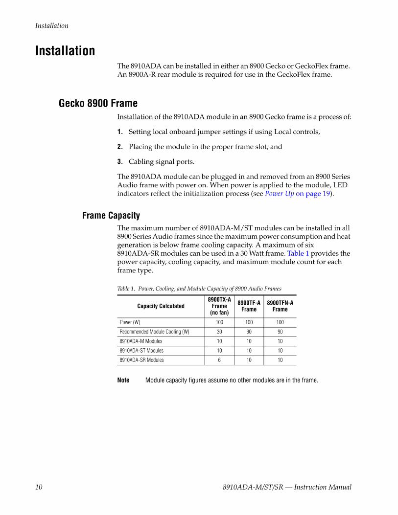
Frame CapacityThe maximum number of 8910ADA-M/ST modules can be installed in all 8900 Series Audio frames since the maximum power consumption and heat generation is below frame cooling capacity. A maximum of six 8910ADA-SR modules can be used in a 30 Watt frame. Table 1 provides the power capacity, cooling capacity, and maximum module count for each frame type.
Note Module capacity figures assume no other modules are in the frame.
Table 1. Power, Cooling, and Module Capacity of 8900 Audio Frames
Capacity Calculated8900TX-A
Frame(no fan)
8900TF-A Frame
8900TFN-A Frame
Power (W) 100 100 100
Recommended Module Cooling (W) 30 90 90
8910ADA-M Modules 10 10 10
8910ADA-ST Modules 10 10 10
8910ADA-SR Modules 6 10 10
10 8910ADA-M/ST/SR — Instruction Manual

Installation
Module Placement in the 8900 FrameThere are ten slot locations in the frame to accommodate either analog or digital modules. These are the left ten locations. Refer to Figure 1.
The two slots on the right are allocated for the power supplies. For addi-tional information concerning the Power Supply module, refer to the Gecko 8900 Frames Instruction Manual.
The third slot from the right is allocated for the controller module—either a Frame Monitor Module or a 8900NET Network Interface Module. For additional information concerning the controller module options, refer to the 8900NET Network Interface Module Instruction Manual.
Figure 1. 8900 Series Audio Frame Slots
Frame Controller or8900NET Module (only)
Power Supplies
(only)
8156_04r1
8900 Audio Media Module
8910ADA-M/ST/SR — Instruction Manual 11

Installation
8900 module slots are interchangeable within the frame. There are 10 three-terminal connectors and 4 BNC connectors in each slot’s I/O group. The functional assignment of each connector in a group is determined by the module that is placed in that slot. The maximum number of modules an 8900 frame can accept is ten. Figure 2 illustrates the rear connector plate for an 8900 Series Audio frame.
Figure 2. 8900 Series Audio Frame Rear Connectors
To install a module in Gecko frame:
1. If using local onboard controls, set jumpers on the module circuit board. Refer to Onboard 8910ADA-M and -ST Configuration on page 22 or Onboard 8910ADA-SR Configuration on page 24 before installing the front module.
2. Insert the module, connector end first, with the component side of the module facing to the right and the ejector tab to the top.
3. Verify that the module connector seats properly against the backplane.
4. Press in the ejector tab to seat the module.
8156_02
J1
J3
J5
J7
J9
J2
J4
J6
J8
J10
J11
J13
J12
J14
IN
1
J1
J3
J5
J7
J9
J2
J4
J6
J8
J10
J11
J13
J12
J14
IN
2
J1
J3
J5
J7
J9
J2
J4
J6
J8
J10
J11
J13
J12
J14
IN
3
J1
J3
J5
J7
J9
J2
J4
J6
J8
J10
J11
J13
J12
J14
IN
4
J1
J3
J5
J7
J9
J2
J4
J6
J8
J10
J11
J13
J12
J14
IN
5
J1
J3
J5
J7
J9
J2
J4
J6
J8
J10
J11
J13
J12
J14
IN
6
J1
J3
J5
J7
J9
J2
J4
J6
J8
J10
J11
J13
J12
J14
IN
7
J1
J3
J5
J7
J9
J2
J4
J6
J8
J10
J11
J13
J12
J14
IN
8
J1
J3
J5
J7
J9
J2
J4
J6
J8
J10
J11
J13
J12
J14
IN
9
J1
J3
J5
J7
J9
J2
J4
J6
J8
J10
J11
J13
J12
J14
IN
10
12 8910ADA-M/ST/SR — Instruction Manual

Installation
GeckoFlex FrameInstallation of the 8910ADA module in a GeckoFlex frame is a process of:
1. Installing the 8900A-R rear module into the rear of the frame,
1. Setting jumpers on the module circuit board if using local onboard controls,
2. Placing the 8910ADA module in the corresponding front frame slot, and
3. Cabling and terminating signal ports.
Module Installation PrecautionsPlease read and follow the precautions listed below before installing the front and rear modules:
• Use standard anti-static procedures during installation. As modules can be installed or removed when the GeckoFlex frame is powered up, before removing the cover, please use an anti-static bracelet tied to a metal part of the frame.
• Install the rear module first, then the front module, then the optical sub-module option (if used).
• When installing or removing a rear module, loosen or tighten the screws holding the retainer clips to the frame manually with the retainer clip tool provided inside the front cover of the frame (751- version frames only). For 650- version frames without the tool, use a 2 mm (5/64”) hex screwdriver. Please do not use an electric screw-driver.
• Make every effort to leave the screws holding the retainer clips in place (do not remove them completely). They are very small and can easily drop into other equipment causing a shorting hazard. (Two turns of the screw should be enough to loosen the screws, 3 turns or more will remove it.)
• When installing a rear module, tighten the screws on the retainer clips just until snug. Do not apply more force than is necessary to seat the rear module. Refer to the Mechanical specification for the 8900A-R rear retainer clip screw torque in Table 6 on page 42.
8910ADA-M/ST/SR — Instruction Manual 13

Installation
Rear Module InstallationTo install a rear module into GeckoFlex frame, follow these steps:
Note Please read Module Installation Precautions on page 13 before installing the rear module.
1. Each 8900A-R rear module or blank rear adapter cover is held in place by two retainer clips as shown in Figure 3. Loosen (but do not remove completely) the two screws holding each retainer clip to the frame with a 2 mm (5/64”) hex screwdriver. Pull up on the retainer to remove it, leaving the screws in place.
CAUTION Be careful to leave the screws in place as they can be easily lost or fall into equipment below the frame creating a shorting hazard.
2. Remove the blank rear adapter cover by inserting needlenose pliers into the slots in the top and bottom of the blank and pulling it off.
Note To remove a rear module already installed, follow the same steps. It is helpful to first remove the front module so the rear can be pulled out more easily.
3. Insert the rear module into the empty slot.
4. Replace each retainer clip over the two screws on both sides of the module and push down to seat the retainer.
5. Tighten the screws for each retainer clip just until they are snug. Do not force or torque the screws too tightly. The rear retainer clip screw torque specification is 4-5-inch-lb./0.45-0.60Nm.
Figure 3. Installing Rear Module
Use needlenose pliersto pull out blank afterremoving retainers.
14 8910ADA-M/ST/SR — Instruction Manual
Installation
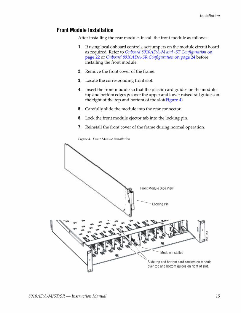
Front Module InstallationAfter installing the rear module, install the front module as follows:
1. If using local onboard controls, set jumpers on the module circuit board as required. Refer to Onboard 8910ADA-M and -ST Configuration on page 22 or Onboard 8910ADA-SR Configuration on page 24 before installing the front module.
2. Remove the front cover of the frame.
3. Locate the corresponding front slot.
4. Insert the front module so that the plastic card guides on the module top and bottom edges go over the upper and lower raised rail guides on the right of the top and bottom of the slot(Figure 4).
5. Carefully slide the module into the rear connector.
6. Lock the front module ejector tab into the locking pin.
7. Reinstall the front cover of the frame during normal operation.
Figure 4. Front Module Installation
Slide top and bottom card carriers on module over top and bottom guides on right of slot.
Module installed
Locking Pin
Front Module Side View
0642
_10r
0
8910ADA-M/ST/SR — Instruction Manual 15

Installation
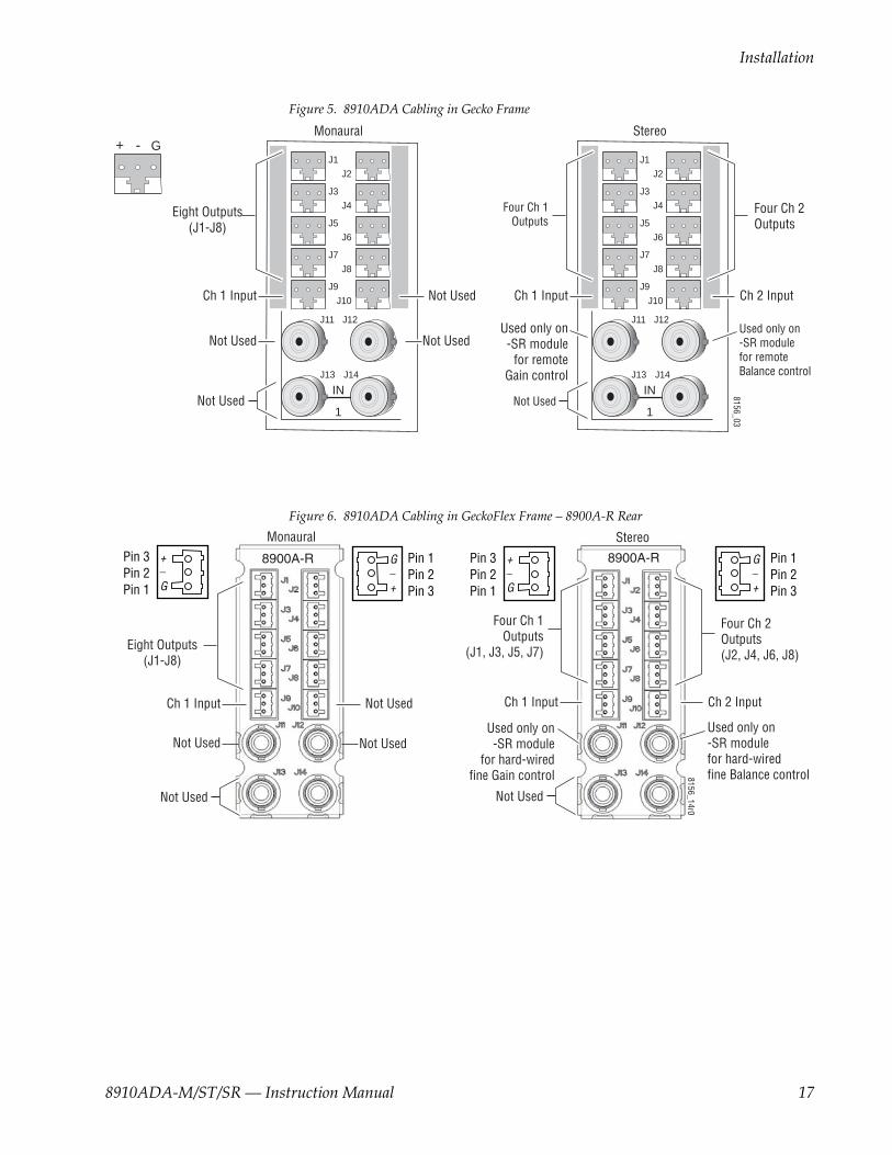
CablingCabling for the module in the Gecko frame is shown in Figure 5 on page 17. For the GeckoFlex frame, refer to the 8900A-R rear module illustration in Figure 6 on page 17.
InputsUnbalanced input loop-through input connectors, J13 or J14 are not used for 8910ADA modules. A balanced input connects to connector J9 for the 8910ADA-M. The stereo 8910 ADA-ST accepts inputs from connectors J9 (Channel 1) and J10 (Channel 2).
OutputsThe 8910ADA-M has eight balanced outputs using connectors J1 through J8. The 8910ADA-ST and SR have four balanced outputs per channel using connectors J1, J3, J5, and J7 for Channel 1 and J2, J4, J6, and J8 for Channel 2.
Note The input mode to the Ch 1 and Ch 2 outputs can be chosen from Ch 1, Ch 2, or the sum of both channels with local or remote controls.
8900-A-CBL OptionAn audio breakout cable assembly consisting of four three-terminal to dual BNCs can be purchased as an option for unbalanced outputs.
Hard-wired Potentiometers (8910ADA-SR Only)For hard-wiring the fine Gain and Balance potentiometers to BNC J11 and J12, refer to Hard-wired Fine Gain/Balance Potentiometer Control on page 18.
16 8910ADA-M/ST/SR — Instruction Manual
Installation
Figure 5. 8910ADA Cabling in Gecko Frame
Figure 6. 8910ADA Cabling in GeckoFlex Frame – 8900A-R Rear
J2
J1
J3
J5
J7
J9
J2
J4
J6
J8
J10
J11
J13
J12
J14
IN
1
J2
J1
J3
J5
J7
J9
J2
J4
J6
J8
J10
J11
J13
J12
J14
IN
1
+ - G8156_03
Eight Outputs(J1-J8)
Stereo
Four Ch 1 Outputs
Four Ch 2Outputs
Not Used
Used only on -SR module
for remoteGain control
Ch 1 Input
Used only on-SR modulefor remote Balance control
Ch 2 Input
Monaural
Not Used
Not Used
Ch 1 Input
Not Used
Not Used
8900A-R 8900A-R
Eight Outputs(J1-J8)
Monaural
Not Used
Not Used
Ch 1 Input
Not Used
Not Used
Pin 3Pin 2Pin 1
Pin 1Pin 2Pin 3
+_
G
Pin 3Pin 2Pin 1
+_
G
G_
+
Pin 1Pin 2Pin 3
G_
+
8156_14r0
Stereo
Four Ch 1 Outputs
(J1, J3, J5, J7)
Four Ch 2Outputs(J2, J4, J6, J8)
Not Used
Used only on -SR module
for hard-wired fine Gain control
Ch 1 Input
Used only on-SR modulefor hard-wiredfine Balance control
Ch 2 Input
8910ADA-M/ST/SR — Instruction Manual 17

Installation
Hard-wired Fine Gain/Balance Potentiometer ControlOn the 8910ADA-SR module only, BNCs J11 and J12 can be connected to external hard-wired customer-supplied potentiometers for fine (± 6 dB) gain and balance adjustment respectively. Overall gain and balance (-12 dB to +30 dB) are set with the front edge paddle switches as explained below.
Note The hardwired potentiometer controls are active only when the module is jumpered for LOC/POT control. The Local/Remote position disables these ports. Refer to Figure 11 on page 24.
When both local paddle switch adjustments and hard-wired potentiometer adjustments are made, the following input gain relationships exist:
• Input 1 gain = hard-wired potentiometer gain + paddle switch gain - paddle switch balance - hard-wired potentiometer balance
• Input 2 gain = hard-wired potentiometer gain + paddle switch gain + paddle switch balance + hard-wired potentiometer balance
These relationships will be reported on the Audio Status/Control web page in read-only mode similar to the one shown in Figure 16 on page 33. When the gain or balance is changed using a paddle switch or one of the potenti-ometers, the web page will update when the user manually refreshes it.
Figure 7 provides a schematic diagram for constructing a user-supplied hard-wired control circuit to connect to these BNCs.
Figure 7. User-supplied Hard-wired Fine Gain and Balance Control Circuits
Connect to J11 for potentiometer fine gain adjust
Connect to J12 for potentiometer fine balance adjust
10 kCW*
* Clockwise rotation increases gain for gain pot and increases gain for channel 2 while decreasing gain for channel 1 for balance pot.
8156
_10r
1
18 8910ADA-M/ST/SR — Instruction Manual
Power Up
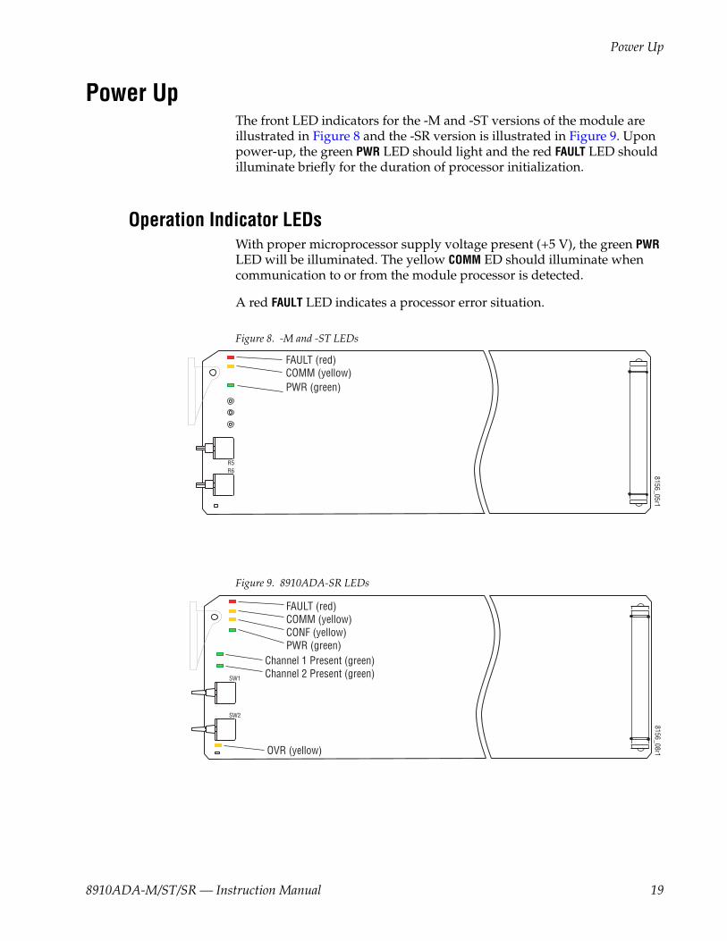
Power UpThe front LED indicators for the -M and -ST versions of the module are illustrated in Figure 8 and the -SR version is illustrated in Figure 9. Upon power-up, the green PWR LED should light and the red FAULT LED should illuminate briefly for the duration of processor initialization.
Operation Indicator LEDsWith proper microprocessor supply voltage present (+5 V), the green PWR LED will be illuminated. The yellow COMM ED should illuminate when communication to or from the module processor is detected.
A red FAULT LED indicates a processor error situation.
Figure 8. -M and -ST LEDs
Figure 9. 8910ADA-SR LEDs
8156_05r1
R5R6
FAULT (red)COMM (yellow)PWR (green)
OVR (yellow)
8156_08r1
FAULT (red)COMM (yellow)CONF (yellow)PWR (green)
SW2
SW1
Channel 1 Present (green)Channel 2 Present (green)
8910ADA-M/ST/SR — Instruction Manual 19

Power Up
Note The yellow COMM and CONF LEDs are used for the module location function that is enabled using the GUI. The module location function causes these LEDs to flash concurrently three times followed by an off state of 900 ms duration. The locate mode can be turned off by toggling the paddle switch on the module.
Table 2 (-M and -ST modules) and Table 3 (-SR module) show the possible LED indications and conditions they indicate.
Table 2. 8910ADA-M/ST Indicator LEDs and Conditions Indicated
Version LED Indication Condition
-M & ST
FAULT(red)
Off Normal operation.
On continuously Module has detected an internal fault.
Long flash Configuration problems. Check inputs and settings.
COMM (yellow)
Off No activity on frame communication bus.
Short flash Activity present on the frame communication bus.
PWR (green)
Off No power to module or module’s DC/DC converter failed.
On continuously Normal operation, module is powered.
Table 3. 8910ADA-SR Indicator LEDs and Conditions Indicated
Version LED Indication Condition
-SR
FAULT(red)
Off Normal operation.
On continuously Module has detected an internal fault.
Long flash Configuration problems. Check inputs and settings.
COMM (yellow)
Off No activity on frame communication bus.
3 short on, 1 long off in sync with CONF LED Location Command received by the module from a remote control system.
Short flash Activity present on the frame communication bus.
CONF (yellow)
Off Module is in normal operating mode.
3 short on, 1 long off in sync with COMM LED Location Command received by the module from a remote control system.
On continuously Module is initializing, changing operating modes or updating firmware.
PWR (green)
Off No power to module or module’s DC/DC converter failed.
On continuously Normal operation, module is powered.
PRESENT 1(green)
Off Input 1 signal is less than selected threshold setting (-20, -40 or -60 dBu).
On continuously Input 1 signal is greater than selected threshold setting (-20, -40 or -60 dBu).
PRESENT 2(green)
Off Input 2 signal is less than selected threshold setting (-20, -40 or -60 dBu).
On continuously Input 2 signal is greater than selected threshold setting (-20, -40 or -60 dBu).
OVR(yellow)
Off In Local/Remote mode, remote settings match local jumper settings on module.
On continuously In Local/Remote mode, remote settings are overriding local jumper settings.
20 8910ADA-M/ST/SR — Instruction Manual

Module Configuration
Module ConfigurationThe 8910ADA-M, -ST is configurable with local onboard controls only. Refer to Onboard 8910ADA-M and -ST Configuration on page 22.
8910ADA-SR configuration and monitoring can be performed with local onboard controls (paddle switches and hard-wired potentiometers) or using a web browser GUI interface or a networked Newton Control Panel.
Table 4 provides a complete summary of the 8910ADA-SR processing func-tions and a comparison of the functionality available with each control type along with the ranges and default values for each parameter.
Table 4. Summary of 8910ADA-SR Configuration Functions
FunctionType Default Range/Choices
ResolutionWeb Page/
Function NameOnboard
Jumpers/Paddles
NewtonControl Panel
Gain adjustment mode Independent Gain
Gain/Bal or Independent Gain
Audio Status/ControlStereo/Dual Mode pulldown See SW2 – GAIN on page 26 St/D Mode
Independent Gain mode 0 dB – 20 to + 30 dB
Audio Status/ControlInput 1 Gain
See SW2 – GAIN on page 26Ip1_Gain
Audio Status/ControlInput 2 Gain Ip2_Gain
Gain (Gain/Bal mode)0 dB – 20 to + 30 dB Audio Status/Control
Gain controlSee SW1 – BAL on page 26, SW2 – GAIN on page 26, and Fine Gain/Balance Hard-wired
Potentiometers on page 26
Gain
0 dB ± 6 dB Audio Status/ControlBalance control Balance
Input 1 Invert Normal Normal or Invert Audio Status/ControlInput 1 Invert
Jumper J2, CHAN 1: Invert – Pins 1-2
Normal – Pins 2-3In1 Invt
Input 2 Invert Normal Normal or Invert Audio Status/ControlInput 2 Invert
Jumper J3, CHAN 2: Invert – Pins 1-2
Normal – Pins 2-3In2 Invt
Output 1 mode Input 1
Input 1 Input 2
Sum 1 + 2
Audio Status/ControlOutput 1 Mode
Jumper P1:Output 1 Mode Select:
Input 1 – pins 1-2Input 2 – pins 3-4
Sum 1 + 2 – pins 5-6Output 2 Mode Select:
Input 1 – pins 7-8Input 2 – pins 9-10
Sum 1 + 2 – pins 11-12
Out1Mode
Output 2 mode Input 2 Audio Status/ControlOutput 2 Mode Out2Mode
Save User Settings – – Recall/Save User Settings/Save User Settings button N/A N/A
Recall User Settings – – Recall/Save User Settings/Recall User Settings button N/A N/A
Recall Factory Defaults See above – Recall/Save User Settings/Recall Fact.Defaults button N/A N/A
8910ADA-M/ST/SR — Instruction Manual 21

Module Configuration
Onboard 8910ADA-M and -ST ConfigurationThe 8910ADA-M and -ST modules can be configured using the jumpers and potentiometers shown in Figure 10.
These components perform the following:
• Jumper blocks JP1 and JP2 (8910ADA-ST only) select the output gain adjustment in increments of 6 dB.
• Card edge potentiometers R5 and R6 (8910ADA-ST only) provide greater than 6 dB gain adjustment within the jumper selected range.
• Jumper JP3 (8910ADA-ST only) can be set to operate an 8910ADA-ST module in Monaural or Stereo mode.
Note Change jumper settings only when module is removed from the frame.
Figure 10. 8910ADA-M and -ST Module Configuration Switches and Jumpers
Monaural or Stereo Mode (-ST Module Only)Set the module output to Monaural or Stereo with the following:
• Jumper, JP3
STEREO – pins 1-2
MONAURAL – pins 2-3
8156_06r1
F1
F2
Gain Ch. 1potentiometer
Gain Ch. 2potentiometer
R5
R6*
*R6, JP2, and JP3 are present on stereo (ST) model only.
+30 db+24 db+18 db+12 db
+6 db0 db
-6 db-12 db
JP1
JP2*
JP3*
Stepped Gain
Monaural/Stereo Select
JP3*
2
1
15
16
STEREO
MONAURAL
(pins 1-2)
(pins 2-3)
STEPPED GAIN 1STEPPED GAIN 2
22 8910ADA-M/ST/SR — Instruction Manual

Module Configuration
Output Gain SelectUse jumpers JP1 and JP2 to set the output gain for Channel 1 and Channel 2 (-ST module only) as follows:
• Stepped Gain 1 (-M and ST modules)
• – 12 dB – pins 1-2
• – 6 dB – pins 3-4
• 0 dB – pins 5-6
• + 6 dB – pins 7-8
• + 12 dB – pins 9-10
• + 18 dB – pins 11-12
• + 24 dB – pins 13-14
• + 30 dB – pins 15-16
• Stepped Gain 1 (-ST module only)
• Identical to Stepped Gain 1 above
Fine Gain PotentiometersAfter selecting the Stepped Gain jumper selection for the channel, adjust potentiometers R5 (Channel 1) and R6 (Channel 2 on the -ST module only) for finer gain adjustment.
8910ADA-M/ST/SR — Instruction Manual 23
Module Configuration
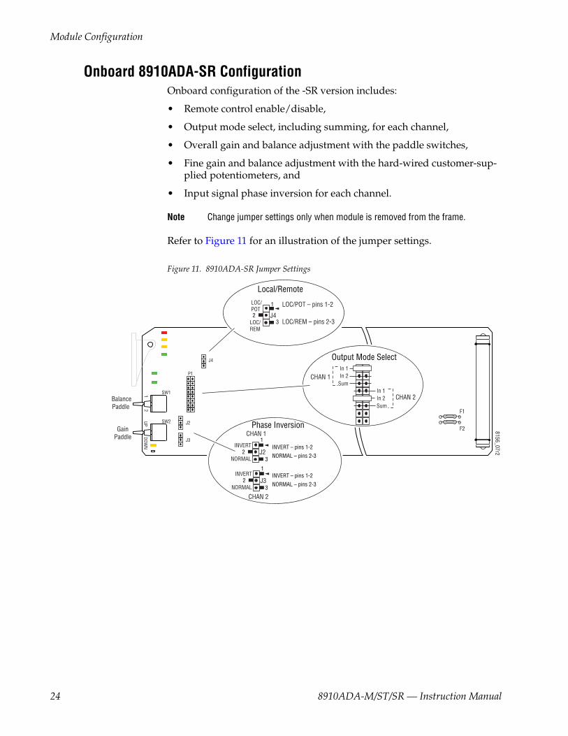
Onboard 8910ADA-SR ConfigurationOnboard configuration of the -SR version includes:
• Remote control enable/disable,
• Output mode select, including summing, for each channel,
• Overall gain and balance adjustment with the paddle switches,
• Fine gain and balance adjustment with the hard-wired customer-sup-plied potentiometers, and
• Input signal phase inversion for each channel.
Note Change jumper settings only when module is removed from the frame.
Refer to Figure 11 for an illustration of the jumper settings.
Figure 11. 8910ADA-SR Jumper Settings
8156_07r2
SW2
SW1BalancePaddle
GainPaddle
F1
F2
In 1In 2
SumIn 1In 2Sum
CHAN 1
CHAN 2
J4
J21
UPDOW
N2
J3
P1
Output Mode Select
J2
Phase Inversion
Local/Remote
CHAN 1
INVERT
NORMAL
CHAN 2
LOC/POT – pins 1-2
LOC/REM – pins 2-3
1
23
J3INVERT
NORMAL
1
23
J4
LOC/POT
LOC/REM
1
23
INVERT – pins 1-2
NORMAL – pins 2-3
INVERT – pins 1-2
NORMAL – pins 2-3
24 8910ADA-M/ST/SR — Instruction Manual

Module Configuration
Local or Remote ControlSet the module for Local or Remote control with jumper J4. When set to LOC/POT (pins 1-2) the module settings are made locally with onboard jumpers and switches and the hard-wired customer-supplied potentiome-ters can be used. In LOC/POTmode, configuration from remote control is locked out.
When LOC/REM (local and remote) is enabled (pins 2-3), configuration can be performed using the onboard switches, jumpers, and/or the web browser or Newton Control Panel. When local settings are changed by the remote control, the yellow OVR LED will illuminate if the remote settings are different than the local ones.
Note The hard-wired potentiometers only work in LOC/POT mode.
Output Mode SelectUse jumper P1 to select the output mode for Channel 1 and Channel 2 as follows:
• CHAN 1 Output
• Input 1 – pins 1-2
• Input 2 – pins 3-4
• Sum 1 + 2 – pins 5-6
• CHAN 2 Output
• Input 1 – pins 7-8
• Input 2 – pins 9-10
• Sum 1 + 2 – pins 11-12
Phase InversionUse jumpers J2 and J3 to set Normal or Inverted input phase as follows for each channel:
• CHAN 1 Phase, Jumper J2
• Invert – pins 1-2
• Normal – pins 2-3
• CHAN 2 Phase, Jumper J3
• Invert – pins 1-2
• Normal – pins 2-3
8910ADA-M/ST/SR — Instruction Manual 25

Module Configuration
Gain and Balance SettingsThe overall gain of each channel can be controlled separately or together by the operation of the two paddle switches, SW1 (BAL) and SW2 (GAIN), on the front edge of the module. The fine gain and balance can be adjusted ±6 dB by using hard-wired potentiometers connected to BNCs J11 and J12.
• SW1 (BAL) – this paddle switch controls the balance between Channel 1 and Channel 2. When SW1 is pushed up (Position 1), the Channel 1 (left) gain is increased in increments of 0.1 dB while the Channel 2 gain (right) is reduced in increments of 0.1 dB. The gain will continue until a maximum increase in gain of + 6 dB has been reached.
Pushing the SW1 paddle switch down (Position 2) will cause the gain of Channel 2 (right) to increase while Channel 1 (left) will decrease in 0.1 dB steps until a maximum increase in gain of + 6 dB is reached.
Holding the paddle in Position 1 or Position 2 for more than 1 second will cause the gain to increase or decrease by 0.1 dB at a faster rate. The total difference in gain between both channels is 12 dB.
• SW2 (Gain) – when SW1 is in the middle position, adjusting SW2 will affect the gain of both channels equally. The gain will be changed in increments of approximately 0.1 dB for each click of the paddle. Any gain differences between channels will be maintained as the gain is changed.
• Fine Gain Hard-wired Potentiometer (BNC J11) – fine gain can be adjusted ±6 dB when a customer-supplied potentiometer is hard-wired to BNC J11 and the module is jumpered for LOC/POT mode. Refer to Hard-wired Fine Gain/Balance Potentiometer Control on page 18.
• Fine Balance Hard-wired Potentiometer (BNC J12) – fine balance can be adjusted ± 6 dB when a customer-supplied potentiometer is hard-wired to BNC J12 and the module is jumpered for LOC/POT mode. Refer to Hard-wired Fine Gain/Balance Potentiometer Control on page 18.
Power Cycle and Control SettingsWhen remote overrides have been set using the remote controls, the OVR LED illuminates. If power is cycled and no local jumper settings are changed, the existing settings will be retained. The module will resume operation as set remotely by the GUI and the OVR LED is again illuminated.
If any local jumper change is made during the power cycle with the module removed from the frame, the module will boot up with the locally set parameters and the OVR LED will be extinguished.
26 8910ADA-M/ST/SR — Instruction Manual

Module Configuration
Remote Configuration and Monitoring
8910ADA-M/ST Remote Configuration and Monitoring8910ADA-M and -ST have limited reporting ability and no remote config-uration functionality.
They will report:
• Module presence,
• Model number,
• Slot ID, and
• Revision and serial numbers.
8910ADA-SR Remote Configuration and Monitoring8910ADA-SR configuration and monitoring can be performed using a web browser GUI interface or a networked Newton Control Panel when the 8900NET (Net Card) Network Interface module is present in the video frame (Gecko 8900TFN-A or GeckoFlex 8900FFN frame). Each of these interfaces is described below.
Note For remote access, make sure the jumper block on the module is set for both Local and Remote access (Figure 11 on page 24).
8900NET Module InformationRefer to the 8900NET Network Interface Module Instruction Manual for infor-mation on the 8900NET Network Interface module and setting up and operating the Gecko 8900 frame network.
Newton Control Panel ConfigurationA Newton Control Panel (hard and/or soft version) can be interfaced to any 8900 Series frame with an 8900NET module over the local network. Refer to the documentation that accompanies the Newton Modular Control System for installation, configuration, and operation information.
Control panel access offers the following considerations for module config-uration and monitoring:
• Ability to separate system level tasks from operation ones, minimizing the potential for on-air mistakes.
• Ability to group modular products—regardless of their physical loca-tions—into logical groups (channels) that you can easily manipulate with user-configured knobs.
• Update software for applicable modules and assign frame and panel IP addresses with the NetConfig Networking application.
8910ADA-M/ST/SR — Instruction Manual 27

Module Configuration
• Recommended for real-time control of module configuration parame-ters, providing the fastest response time.
Note Not all module functions are available with the control panel, such as E-MEM and factory default recalls. The available control panel controls for the module are listed in Table 4 on page 21.
An example of the Newton Configurator is shown in Figure 12.
Figure 12. Newton Configurator Example
Web Browser InterfaceThe web browser interface provides a graphical representation of module configuration and monitoring.
Use of the web interface offers the following considerations:
• Provides complete access to all module status and configuration func-tions, including naming of inputs and outputs, factory parameter and name default recalls, E-MEM functions, slot configuration, and SNMP monitoring controls.
• Web access will require some normal network time delays for pro-cessing of information.
• Configuration parameter changes may require pressing Apply button or Enter, upload processing time, and a manual screen refresh to become effective.
• Web interface recommended for setting up module signal and slot names, E-MEMS, and reporting status for SNMP and monitoring.
28 8910ADA-M/ST/SR — Instruction Manual

Module Configuration
Refer to the Frame Status page shown in Figure 13. The 8900 modules can be addressed by clicking either on a specific module icon in the frame status display or on a module name or slot number in the link list on the left.
Note The physical appearance of the web page displays on the web pages shown in this manual represent the use of a particular platform, browser and version of 8900NET module software. They are provided for reference only. Web page displays will differ depending on the type of platform and browser you are using and the version of the 8900NET software installed in your system. This manual reflects 8900NET software version 4.2.0.
For information on status and fault monitoring and reporting shown on the Frame Status page, refer to Status Monitoring on page 43. The 8900 modules can be addressed by clicking on a specific module icon in the frame status display or on a module name or slot number in the link list on the left.
Figure 13. Frame Status Web Page
8156_11r2
The Links section lists the frame and its current modules. The selected link's Status page is first displayed and the sub-list of links for the selection is opened. The sub-list allows you to select a particular information page for the selected device.
Content display section displays the information page for the selected frame or module (frame slot icons are alsoactive links).
Refresh button for manual update of page
8910ADA-M/ST/SR — Instruction Manual 29
Module Configuration
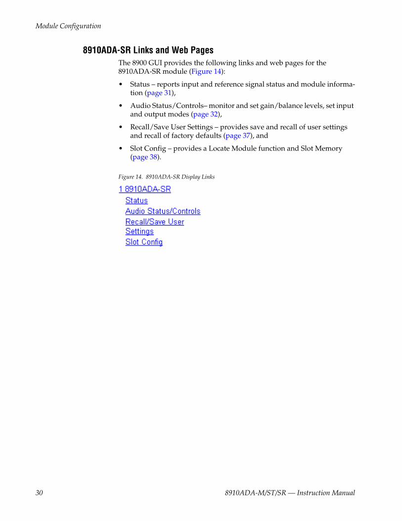
8910ADA-SR Links and Web PagesThe 8900 GUI provides the following links and web pages for the 8910ADA-SR module (Figure 14):
• Status – reports input and reference signal status and module informa-tion (page 31),
• Audio Status/Controls– monitor and set gain/balance levels, set input and output modes (page 32),
• Recall/Save User Settings – provides save and recall of user settings and recall of factory defaults (page 37), and
• Slot Config – provides a Locate Module function and Slot Memory (page 38).
Figure 14. 8910ADA-SR Display Links
30 8910ADA-M/ST/SR — Instruction Manual
Module Configuration
Status Web Page
Usethislink
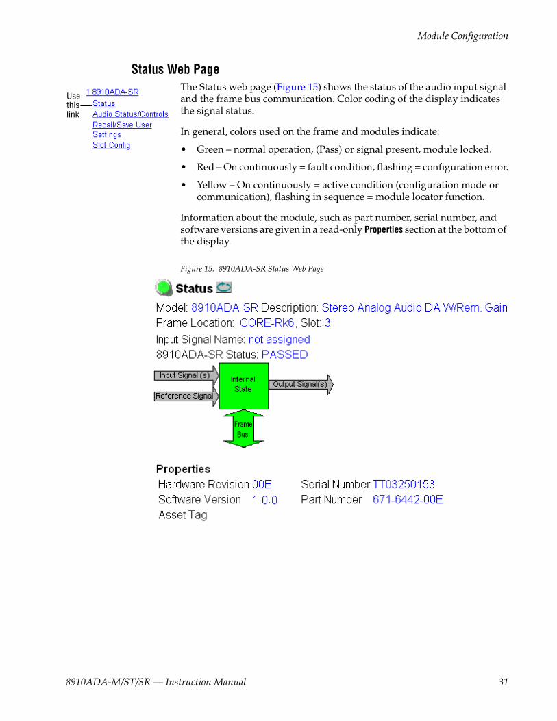
The Status web page (Figure 15) shows the status of the audio input signal and the frame bus communication. Color coding of the display indicates the signal status.
In general, colors used on the frame and modules indicate:
• Green – normal operation, (Pass) or signal present, module locked.
• Red – On continuously = fault condition, flashing = configuration error.
• Yellow – On continuously = active condition (configuration mode or communication), flashing in sequence = module locator function.
Information about the module, such as part number, serial number, and software versions are given in a read-only Properties section at the bottom of the display.
Figure 15. 8910ADA-SR Status Web Page
8910ADA-M/ST/SR — Instruction Manual 31

Module Configuration
Audio Status/Controls Web Page
Usethislink
The Audio Status/Controls web page allows you to perform the following function for the 8910ADA-SR:
• Monitor actual gain levels for each channel (a function of Gain and Bal-ance) in both local and remote modes,
• Select Gain and Balance adjustment mode – Gain/Balance or Indepen-dent Gain,
• Set Gain and Balance levels,
• Select Normal or Inverted input, and
• Select output mode – Input 1, Input 2, or - 6 dB Sum of both inputs.
Click the Apply button to activate a selection.
When YES is reported in the input monitoring information (Input 1 and Input 2 Present), a signal of greater than -40 dBu has been detected at the input. When the input detected is less than -40 dBu, NO is displayed.
If the onboard jumper for Local/Remote operation is in the LOC/POT position (see Figure 11 on page 24), the Audio Status/Controls display will be in read-only mode (see Figure 16 on page 33) and only local onboard control is enabled. When set for Local control only, setting of overall gain and balance is done using the front paddle switches on the module and for fine gain and balance adjustment, the hard-wired customer-supplied potentiometers connected to BNCs J11 and J12 can be used.
When in LOC/POT mode, the Audio Status Controls web page will con-tinue to report the changes made with the local controls. The user must manually refresh the page using the Refresh button at the top of the web page each time a change is made with a local control for the web page to update to the current local settings.
A Fault text message will appear for the Gain or Balance Potentiometer status if no potentiometer is detected. When potentiometers are detected, the status will report Present as shown in Figure 16 on page 33.
Note Fault reports for the hard-wired potentiometers are not reflected on the Frame Status web page.
32 8910ADA-M/ST/SR — Instruction Manual

Module Configuration
Figure 16. Audio Status/Controls Web Page – LOC/POT Mode Enabled
8910ADA-M/ST/SR — Instruction Manual 33
Module Configuration
When Local/Remote control is enabled (onboard jumper J4 is set to LOC/REM as shown in Figure 11 on page 24), the Audio Status/Controls web page shown in Figure 17 on page 35 will be available.
Gain adjustment mode can be set in one of two Stereo/Dual modes:
• Gain/Balance (Figure 17 on page 35), or
• Independent Gain (Figure 18 on page 36).
Gain/Balance ModeIn Gain/Balance mode, the gain median point is set in the gain window (from -20 to +30 dB). The balance window allows a balance adjustment of plus or minus 6 dB for each channel with 12 dB total difference in gain between the channels at ± 6 dB balance setting. Gain and balance adjust-ments are in 0.1 dB increments.
Note Non-zero balance value entries will preclude full range of Gain adjustment.
Note Gain value entries within 6 dB of -20 dB or +30 dB will preclude full range of balance adjustment.
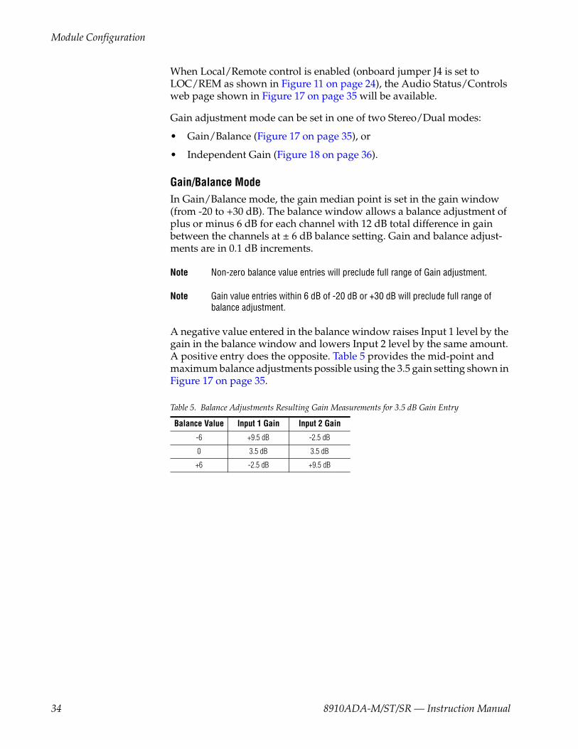
A negative value entered in the balance window raises Input 1 level by the gain in the balance window and lowers Input 2 level by the same amount. A positive entry does the opposite. Table 5 provides the mid-point and maximum balance adjustments possible using the 3.5 gain setting shown in Figure 17 on page 35.
Table 5. Balance Adjustments Resulting Gain Measurements for 3.5 dB Gain Entry
Balance Value Input 1 Gain Input 2 Gain
-6 +9.5 dB -2.5 dB
0 3.5 dB 3.5 dB
+6 -2.5 dB +9.5 dB
34 8910ADA-M/ST/SR — Instruction Manual

Module Configuration
Figure 17. Audio Status/Controls Web Page – Gain/Bal Mode
8910ADA-M/ST/SR — Instruction Manual 35
Module Configuration
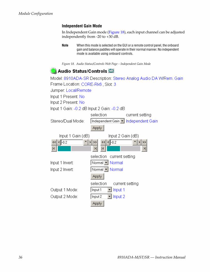
Independent Gain ModeIn Independent Gain mode (Figure 18), each input channel can be adjusted independently from -20 to +30 dB.
Note When this mode is selected on the GUI or a remote control panel, the onboard gain and balance paddles will operate in their normal manner. No independent mode is available using onboard controls.
Figure 18. Audio Status/Controls Web Page – Independent Gain Mode
36 8910ADA-M/ST/SR — Instruction Manual

Module Configuration
Recall/Save User Settings Web Page
Usethislink
The Recall/Save User Settings web page (see Figure 19) allows you to set the following parameters:
• Use the Recall User Settings button to recall previously saved User Set-tings,
• Save the currently selected settings for the entire module with the Save User Settings button, or
• Recall factory default settings with the Recall Fact. Default button.
Figure 19. Recall/Save User Settings Web Page
8910ADA-M/ST/SR — Instruction Manual 37
Module Configuration
Slot Config Web Page
Usethislink
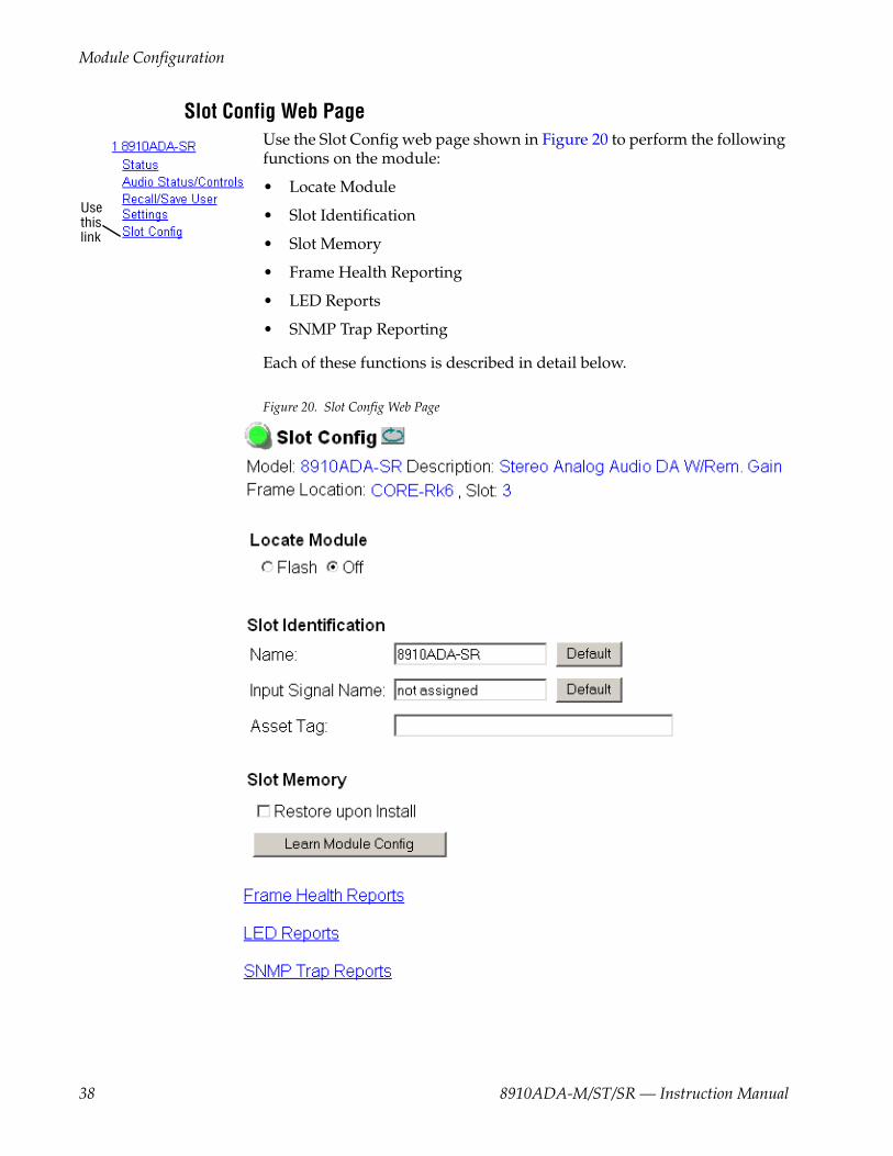
Use the Slot Config web page shown in Figure 20 to perform the following functions on the module:
• Locate Module
• Slot Identification
• Slot Memory
• Frame Health Reporting
• LED Reports
• SNMP Trap Reporting
Each of these functions is described in detail below.
Figure 20. Slot Config Web Page
38 8910ADA-M/ST/SR — Instruction Manual

Module Configuration
Locate ModuleSelecting Flash from the Locate Module pulldown flashes the yellow COMM and CONF LEDs on the front of the module so it can be located in the frame.
Slot IdentificationYou may identify the module by typing a specific name in the Name field. The assigned name is stored on the 8900NET module and travels with the 8900NET module if it is moved to another frame. Select Default to enter the factory default module name.
An asset identification of up to 16 characters may be entered in the Asset Tag field. This will appear on the module Status web page and in the NetConfig inventory report.
Slot MemoryThe slot configuration for each media module is automatically saved peri-odically (once an hour) to the 8900NET module in that frame. You may also select the Learn Module Config button at any time to save the current configu-ration for this slot. The configuration is saved on the 8900NET module. If the 8900NET module is removed or powered down, the stored configura-tions are not saved.
When the Restore upon Install box has been checked, the current configuration saved to this slot is saved as slot memory. When the current module is removed and another module of the same part number and software version is installed, the configuration saved to the 8900NET module will be downloaded to the new module. The box must be checked before the current module with the saved configuration is removed.
Note Only the same module part number, with the same version software should be installed in this slot. Inserting a similar module with a different version software can cause unexpected results.
If a different type of module is installed in this slot, a warning message will state that the original module type has been replaced with another module type. In this case, a Clear button will appear allowing you to clear the stored configuration from the previous module.
Note Uncheck the Restore Upon Install button before downloading new software.
8910ADA-M/ST/SR — Instruction Manual 39
Module Configuration
LED Reports LinkSelect the LED Reports link to open the 8900NET LED Reporting web page. Normally, every module in the frame will report to the 8900NET module any Fault, Signal Loss, Reference Loss, or Config Error conditions. These conditions will be reflected by the status LEDs on the 8900NET module. Using this web page, any of these conditions can be disabled from being reported to the 8900NET module for each individual module and other components (power supplies, fans) in the frame
SNMP Trap Reports LinkSelect the SNMP Trap Reports link to open the 8900NET SNMP Reporting web page. This link will only be present when SNMP Agent software has been installed on the 8900NET module. This web page allows configura-tion of which alarms and warnings that are reported to the SNMP manage-ment software.
Refer to the 8900NET Instruction Manual for complete details on using the 8900NET web pages.
40 8910ADA-M/ST/SR — Instruction Manual

Software Updating
Software UpdatingSoftware updating, if available, for the module is done using the 8900-FLOAD-CBL assembly available from Grass Valley Customer Service.
The 8900-FLOAD-CBL assembly consists of a circuit board and serial and ribbon cables that connect between a serial port on a PC and the ISP con-nector on an 8900 or 2000 module. The software upgrade requires down-loading files from a PC to the module through the cable assembly.
Equipment RequiredThe following items are required for this procedure:
• 8900-FLOAD-CBL assembly kit (circuit board and 2 cables),
• Software CD containing ModLoad.exe application (comes with 8900-FLOAD-CBL kit) and 8900/2000 module software files and Release Notes, and
• PC with unused Serial Com port that can be connected serially to the 8900 or 2000 frame.
Acquiring Software UpdatesFor information on acquiring the upgrade kit and available software updates, contact Grass Valley Customer Service at the location given in Contacting Grass Valley on page 4 at the front of this manual.
8910ADA-M/ST/SR — Instruction Manual 41

Specifications
SpecificationsTable 6. 8910ADA Specifications
Parameter Value
Input
Signal level +30 dBu maximum
Impedance > 18 k¾
Common mode rejection > 72 dB 20 Hz to 20 kHz
Outputs
Number of outputs Monaural, 8 balanced; Stereo, 4 balanced per channel
Signal level -M/-ST modules, +24 dBu maximum-SR module, +28 dBu maximum
Output impedance < 50 ¾ balanced
Level match between outputs Worst case ± 0.25 dB
Output to output isolation > 100 dB
Drive capability -M/-ST modules, 600 ¾ minimum load impedance-SR module will drive a maximum of 3 outputs at a time into 600¾
Performance
Frequency response ±0.05 dB, -0.1 dB wrt/1 kHz, 20 Hz to 20 kHz
THD + N -M/-ST modules, <0.01% @ 24 dBu (-80 dB)-SR module, <0.05% @ +24 dBu (-66 dB)
IM distortion -M/-ST modules, <0.005% (-86 dB)-SR module, <0.025% (-72 dB)
Noise -M/-ST modules, -86 dBu maximum (RMS, 22.4-22.4 kHz, unweighted)-SR module, -75 dBu maximum (RMS, 22.4-22.4 kHz, unweighted)
Gain range -M/-ST modules, -15 to +33 dB -SR module, -20 to +30 dB
Environmental
Frame temperature rangeSee Gecko 8900 or GeckoFlex 8900 frames manual at this link:www.thomsongrassvalley.com/doc/modularOperating humidity range
Non-operating temperature
Mechanical
Frame type 8900 Gecko Audio frame or GeckoFlex with rear module
GeckoFlex frame rear module type 8900A-R rear module
Rear module retainer clip screw torque 4-5 inch-lb./0.45-0.6Nm
Hard-wired potentiometers at J11 and J12 (8910ADA-SR only)
Customer-supplied, 10k ohm, for fine gain and balance adjustment range of ±6 dB
Power Requirements
Supply voltage +12 V, -12 V
Power consumption -M/-ST modules, 3.0 Watts-SR module, 5.0 Watts
Fusing 1.5 A, Slo-Blo (F1, F2)
42 8910ADA-M/ST/SR — Instruction Manual
Status Monitoring
Status MonitoringThis section provides a summary of status monitoring and reporting for a Gecko or GeckoFlex 8900 Series system. It also summarizes what status items are reported and how to enable/disable reporting of each item. There are a number of ways to monitor status of modules, power supplies, fans and other status items depending on the method of monitoring being used.
8900 Frame status will report the following items:
• Power supply health,
• Status of fans in the frame front cover,
• Temperature,
• Module health, and
• Frame bus status.
Module health status will report the following items:
• Internal module state (and state of submodule or options enabled) including configuration errors (warning), internal faults, and normal operation (Pass).
• Signal input states including valid/present (pass), not present or invalid (warning), not monitored, and not available (no signal inputs).
• Reference input states including locked/valid (pass), not locked/invalid (warning), and not monitored.
LEDs LEDs on modules in the frame and on the front of the 8900TF/TFN frames indicate status of the frame and the installed power supplies, fans in the front covers, and modules. (The 8900TX-V/A frames have no LED indica-tors on the front cover.)
When a red FAULT LED is lit on a frame front cover, the fault will also be reported on the 8900NET or Frame Monitor module. The LEDs on the front of these modules can then be read to determine the following fault condi-tions:
• Power Supply 1 and 2 health,
• Fan rotation status,
• Frame over-temperature condition,
• Frame Bus fault (8900NET only), and
• Module health bus.
8910ADA-M/ST/SR — Instruction Manual 43

Status Monitoring
In general, LED colors used on the frame and modules indicate:
• Green – normal operation, (Pass) or signal present, module locked.
• Red – On continuously = fault condition, flashing = configuration error.
• Yellow – On continuously = active condition (configuration mode or communication), flashing in sequence = module locator function.
Status LEDs for this module are described in 8910ADA-M/ST Indicator LEDs and Conditions Indicated on page 20. LEDs for the 8900NET module are described in the 8900NET Network Interface Instruction Manual.
Frame AlarmA Frame Alarm connection is available on pins 8 and 9 of the RS-232 con-nector on the rear of the 8900 frame (Frame Monitor or 8900NET Network Interface module required). This will report any of the status items enabled with the 8900NET or Frame Monitor module configuration DIP switch. Connection and use of the Frame Alarm is covered in detail in the 8900NET Network Interface Instruction Manual.
Web Browser Interface When the 8900NET module is installed in the frame, a web browser GUI can indicate frame and module status on the following web pages:
• Frame Status web page – reports overall frame and module status in graphical and text formats.
• Module Status web page – shows specific input and reference signal status to the module along with enabled options and module versions.
• A Status LED icon on each web page to report communication status for the frame slot and acts as a link to the Status web page where warnings and faults are displayed (8900NET version 3.0 or later).
In general, graphics and text colors used indicate the following:
• Green = Pass – signal or reference present, no problems detected.
• Red = Fault – fault condition.
• Yellow = Warning – signal is absent, has errors, or is mis-configured.
• grey = Not monitored (older 8900 module).
• White = Not present.
Status reporting for the frame is enabled or disabled with the configuration DIP switches on the 8900NET module. Some module status reporting items can also be enabled or disabled on individual configuration web pages.
44 8910ADA-M/ST/SR — Instruction Manual

Status Monitoring
SNMP Reporting The 8900 Series system uses the Simple Network Monitoring Protocol (SNMP) internet standard for reporting status information to remote mon-itoring stations. When SNMP Agent software is installed on the 8900NET module, enabled status reports are sent to an SNMP Manager such as the Grass Valley’s NetCentral application.
There are both hardware and software report enable switches for each report. Both must be enabled for the report to be sent. Software report switches are set on the 8900NET Configuration web page for the Frame, the 8900NET module, and each module slot. Refer to the 8900NET Network Interface Instruction Manual for installation instructions.
8910ADA-M/ST/SR — Instruction Manual 45
Service
ServiceThe 8910ADA modules make extensive use of surface-mount technology and programmed parts to achieve compact size and adherence to demanding technical specifications. Circuit modules should not be ser-viced in the field except to change fuses unless directed otherwise by Cus-tomer Service.
If your module is not operating correctly, proceed as follows:
• Check frame and module power and signal present LEDs.
• Verify power at the voltage testpoints (see Figure 21 on page 47) and check Fuses F1 and F2 if no voltage is detected.
• Check for presence and quality of input signals.
• Verify that source equipment is operating correctly.
• Check cable connections, especially when using the hard-wired cus-tomer-supplied potentiometers for the 8910ADA-SR.
• Check output connections for correct I/O mapping (correct input con-nector is used for the corresponding channel output).
If the module is still not operating correctly, replace it with a known good spare and return the faulty module to a designated Grass Valley repair depot. Call your Grass Valley representative for depot location.
Refer to the Contacting Grass Valley on page 4 at the front of this document for the Grass Valley Customer Service contact number in your region.
46 8910ADA-M/ST/SR — Instruction Manual

Service
Figure 21. Fuse and Voltage Testpoint Locations8156_12r2
R5R6
+12 V testpoint +5 V testpoint-12 V testpoint 1.5 amp
125 V fuses
F1
F2
8910ADA-M/-ST
8910ADA-SR
8156_08r1
SW2
SW1
1.5 amp Slo-Blo125 V fuses
F1
F2
J1
VoltageTest Points
+18V
+5V-5V
-12V
+12V
-18V
8910ADA-M/ST/SR — Instruction Manual 47

Functional Description
Functional Description
8910ADA-M/-ST Refer to the block diagram in Figure 22 while reading the following func-tional description for the 8910ADA-M and 8910ADA-ST modules.
Figure 22. 8910ADA-M/-ST Block Diagram
The 8910ADA-M Analog Audio DA module is an analog audio distribution amplifier (DA) that has one balanced bridging input. The input can be amplified over a range of -12 to +30 dB by setting an eight-position jumper that has 6 dB gain change per step. A front panel gain adjustment has an adjustment range of larger than 6 dB to allow continuous adjustment from step to step on the gain jumper. The output can drive eight balanced and
8156-01r1
Balanced Input
Balanced Input
CH 1/Monaural
Input
CH 2Input
Present on Stereo DA Only
RegulatedPower Supplies
Processor
PWR
COMMFAULT
Monaural
CH 1/MonauralOutputs
CH 2/MonauralOutputs
Stereo
SelectableGain Amp
SelectableGain Amp
Output Amps
Gainrange >6 db
Gainrange >6 db
Stepped gain6 db per step
Stepped gain6 db per step
-12
+
-
+
-
+30 CH1x4
(Jumper JP3pins 1-2)
(Jumper JP3pins 1-2)
(Jumper JP3pins 2-3) CH1x8
CH2x4
-12 +30
Stereo
48 8910ADA-M/ST/SR — Instruction Manual

Functional Description
bridging inputs to +24 dBu. Each output uses a separate monolithic ampli-fier providing very good isolation between outputs.
The 8910ADA-ST DA modules provides a second channel with another set of gain controls as described above. The stereo module provides four bal-anced outputs for each channel capable of driving bridging inputs to +24 dBu.
Analog CircuitryBecause Channel 2 (present on the stereo version) is identical, only Channel 1 will be described here.
The input amplifier is one of two differential receivers. In the monaural DA, the second differential receiver is not connected to any other stages since it is not used on that DA. The input differential receiver has a gain of -12 dB, which is set by the internal gain resistors and the inverting feedback ampli-fier.
The output of the input amplifier feeds a resistor network that includes a front edge gain potentiometer that can be adjusted over a range greater than ±3 dB. This range allows the gain to span the fixed gain setting steps (6 dB per step).
The input into the step gain stage is capacitor-coupled so that any offset in the input stage is not amplified at the output of the DA The gain of the stepped gain stage is set by selecting taps on an R-2R ladder network. Each tap provides 6 dB of attenuation of the stepped gain stage output and is fed back into the inverting input. This has the effect of causing the overall gain from the non-inverting input to increase by 6 dB.
The output of the stepped gain stage feeds the non-inverting input of one of the output stage amplifiers. This amplifier sets the output gain while the second amplifier inverts the first and produces the second differential output. Each differential output has a dual amp IC to drive the outputs. This provides high isolation between stages.
All analog audio stages are powered from the filtered ±12 V supplies to have enough head room to meet the +30 dBu maximum specification for input levels.
8910ADA-M/ST/SR — Instruction Manual 49
Functional Description
MicroprocessorThe microprocessor is an OTP (one time programmable) processor that reports to the network the module’s:
• Model number,
• Version number
• Serial number, and
• Slot ID
A serial EPROM stores the version and serial number for the board. The COMM and FAULT LEDs are controlled by the processor.
Power SupplyThere is one regulated supply on the board producing the 5 volts used by the processor and associated circuitry. When the 5 volts supply is running, the PWR LED is powered on.
50 8910ADA-M/ST/SR — Instruction Manual
Functional Description
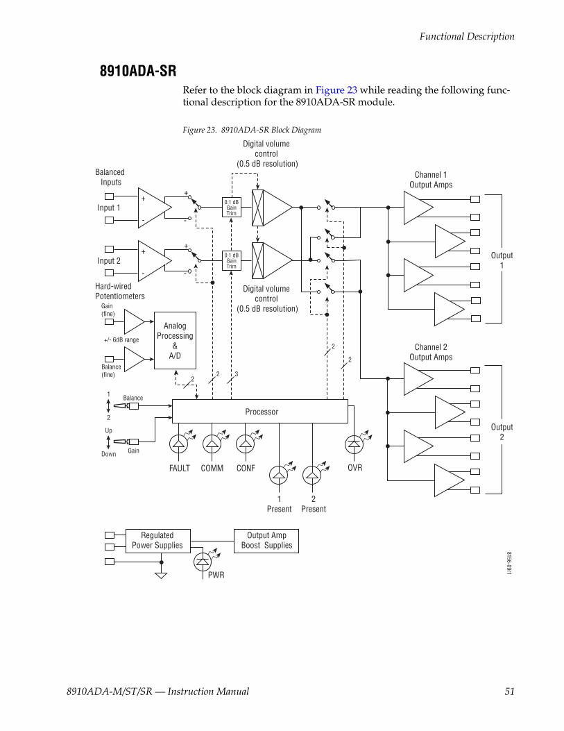
8910ADA-SRRefer to the block diagram in Figure 23 while reading the following func-tional description for the 8910ADA-SR module.
Figure 23. 8910ADA-SR Block Diagram
8156-09r1
Balanced Inputs
Hard-wired Potentiometers
RegulatedPower Supplies
Output AmpBoost Supplies
Processor
PWR
OVRFAULT
Output1
Output2
Digital volume control
(0.5 dB resolution)
Digital volume control
(0.5 dB resolution)
Channel 1Output Amps
Channel 2Output Amps
++
- -
COMM CONF
1Present
2Present
Input 2
Input 1
++
-
Gain (fine)
+/- 6dB range
Gain
Up
Down
1
2
2
-
0.1 dBGainTrim
0.1 dBGainTrim
AnalogProcessing
&A/D
Balance (fine)
Balance
2
2
2
3
8910ADA-M/ST/SR — Instruction Manual 51

Functional Description
Inputs and OutputsThere are two balanced audio inputs. Each input has a three-terminal con-nector.
There are four balanced outputs per channel making a total of eight out-puts. Each output has a three-terminal connector. The output level maximum for the 8910ADA_SR is +28dBu when working into a bridging input.
Processor SectionThe serial EEPROM is used to save the serial number of the board, model number, revision level of hardware and software, and gain calibration. It also saves the gain and jumper configuration settings that are used by the board at start up.
Analog Audio PathThe balanced inputs for inputs 1 and 2 are part of a dual balanced receiver IC. The output of the balanced receivers is routed to the front of the board where it is inverted and sent back to the non-inverting reference point of the input stage. This feedback causes the output of the receiver to have a gain of -12 dB. It also makes available both non-inverted and inverted signals which are selected by the second stage to correct for inversions at the input.
The output of the Invert Non-invert Select stage feeds the top of the dual digital potentiometers. These potentiometers are used to vary the gain in 0.1dB steps between the 0.5dB steps of the volume control that follows it. High impedance unity gain amplifiers buffer the wiper on the digital potentiometer to the inputs of the stereo volume control. The stereo volume control has a gain range of +30 dB to completely mute and is controlled through a three-wire interface to the processor. The digital potentiometer is also controlled by the same three-wire interface with both devices daisy chained together. The digital potentiometer is the first device in the chain followed by the stereo volume control. When the DA is set for unity gain (0dB), both the digital potentiometer and the stereo volume will have approximately 0dB of gain through each device.
The next stage handles channel swapping, monaural, and summing modes. The transmission switches control these modes for channel 1 and channel 2 respectively. There is a gain of 10.4 dB through this stage for all modes except sum. During sum the level of both channels are reduced by 6 dB. Each channel can separately output channel 1 or channel 2 inputs or sum channel 1 and channel 2 to its output. To do a channel swap, channel 2 input is selected for channel 1 output and channel 1 input is selected for channel 2 output. A sum of each channel can be done on each output sepa-rately or at the same time.
52 8910ADA-M/ST/SR — Instruction Manual
Functional Description
The outputs of the swapping/summing stages are sent to the output stages that buffer the signal and add another gain of 3.58 dB. This output is then inverted to give the inverting output of the differential output.
Power SuppliesThere are four regulated power supplies on this board for generating the ±5 V supplies for the processor and the digitally controlled gain stages and the ±18 V supplies. These supplies boost the ±12 V from the frame up to 18 V for the output stages. The ±12 V raw voltages coming onto the board are filtered with passive filters to be used by all audio stages except for the digital gain stage and output stages.
Input Level DetectorsThe input level is detected by taking the audio signal just after the input stage and half wave rectifying it and then filtering it with a low cut off low pass filter. This low pass voltage is then input to the four-channel A/D con-verter. The software in the processor determines the user-selected threshold for -20, -40, or -60 dBu level input.
Hard-wired Fine Gain and Balance PotentiometersThe hard-wired gain and balance controls uses a 10k ohm potentiometer to ground on the two unbalanced BNCs J11 (Gain) and J12 (Balance) at the back of the frame. These potentiometers adjust fine gain and fine balance (± 6 dB range). U15 C&D buffer and offset the current created at their inputs by the gain and balance potentiometers. The processor reads the A/D and translates the reading into a gain or balance value to the digital potentiom-eters and stereo volume control. The Local/Remote jumper on the module circuit board must be set to LOC/POT for these pots to function.
8910ADA-M/ST/SR — Instruction Manual 53

Functional Description
54 8910ADA-M/ST/SR — Instruction Manual
Index
Numerics8900 frame
frame alarm 44status reporting 43
8900A-R rear modulecabling 17installation 14
8900-FLOAD-CBL assembly 418910ADA
features 9specifications 55
Aaudio breakout cable 16Audio Status/Controls web page
Gain/Balance mode 32Independent Gain mode 36
Bbackplane 12blank rear cover 14block diagram
8910ADA-M and ST 488910ADA-SR 51
Ccabling
Gecko frame 16GeckoFlex rear 8900A-R rear module 16inputs and outputs 16
Clear button 39configuration
local8910ADA-M and ST 228910ADA-SR 24
remote8910ADA-M and ST 278910ADA-SR 27
Remote, GUI 21, 27summary table 21
connectors 12input/output 16
control interruption 26control panel
control summary table 21overview 27
controller module 11cycled power 26
Ddocumentation online 4
Eenable SNMP 45environmental 42
Ffactory defaults
recalling 37summary table 21
FAQ database 4fault 19FAULT LED
troubleshooting 43flashing LEDs 20frame 11, 42
module placement 11frame alarm 44frame capacity 10Frame Status page 44frequently asked questions 4front module
installation 15fuse 42, 46
8910ADA-M/ST/SR — Instruction Manual 55

Index
Ggain 32Gain/Balance mode
definition 34Gecko 8900 Frame
module installation 10GeckoFlex frame
module installation 13graphical user interface (GUI) 30Grass Valley web site 4
Hhard-wired potentiometers (8910ADA-SR only)
circuit description 53enabling in LOC/POT mode 18making adjustments 26specifications 55wiring diagram 18
IIndependent Gain mode 36indicators 19input
cabling 16specifications 42
input monitoring 32installation 10
8900A-R rear module 14front module 15Gecko frame 10GeckoFlex frame 13precautions 13
invert 32
Jjumpers
8910ADA-M and ST modules 228910ADA-SR module 24LOC/POT 32
LLED Reporting 41
LED Reporting web page 40LEDs
8910ADA-M and STdefinitions 20locations 19
8910ADA-SRdefinitions 20locations 19
LOC/POT 25local/remote 34locate module 20Locate Module function 39
Mmodule
controller 11installation 11power supply 11slots 12
module health status 43module installation precautions 13module locating function 20module parameters
summary table 21Module Status page 44
NNewton Control Panel
overview 27summary table 21
Oonline documentation 4output mode 32output specifications 42outputs
cabling 16level adjustments 27specifications 42
Pperformance 42
56 8910ADA-M/ST/SR — Instruction Manual

Index
potentiometersfront edge for 8910ADA-M and -STmodules 22hard-wired for 8910ADA-SR 18
power 42power cycling 26power supply 11
Rrear connectors 12rear module
installation precautions 13rear retainer clips (8900A-R)
screw torque 14, 42remote configuration
user settings 37repair depot 46report enable switches 45resuming power 26
SSlot Config web page 38slot memory 39SNMP reporting
overview 45web page for enabling 40
software download from web 4software updating 41status monitoring 43Status web page 31sum 32
Ttestpoints 46troubleshooting 46
Uuser settings
saving and recalling 37
Vvoltage 42
voltage testpoints 46
Wweb browser
overview 28web site
documentation 4FAQ database 4Grass Valley 4software download 4
8910ADA-M/ST/SR — Instruction Manual 57

Index
58 8910ADA-M/ST/SR — Instruction Manual