8vhu 0dqxdo - perfect power systemsperfectpowersystems.com/pdf/extseries_tm.pdf3huihfw 3rzhu 6\vwhpv...
TRANSCRIPT
User Manual
Harsh Environment UPS
EX-Series (3KVA ~ 20 KVA) Document No. 6005-056 Revision E
Installation and Operation
*Due to continuous product improvement this document is subject to change without prior notice.

Perfect Power Systems
6005-056 Rev E a
Perfect Power Systems, Inc
Proprietary Reproduction or Distribution forbidden
NOTICE: THIS DOCUMENT CONTAINS PROPRIETARY INFORMATION
This document contains proprietary and confidential information of Perfect Power Systems, Inc. In consideration of the receipt of this document, the recipient agrees not to copy any of its contents, nor disclose them to or allow them to be used by any person not currently a Perfect Power Systems employee or an employee of the recipient having a need to know, without the express written consent of Perfect Power Systems, and further agrees to surrender this document to Perfect Power Systems when the reason for its receipt has terminated.

Perfect Power Systems
6005-056 Rev E b
EX UPS
Congratulations on selecting one of the fine products from Perfect Power Systems, the Leader in Power Protection Technology. Our wide product offering includes Uninterruptible Power Systems (UPS), Power Conditioners, Automatic Voltage Regulators and Specialty Transformers (e.g. computer-grade, medical-grade). Since our beginning, Perfect Power Systems has shipped many of these fine products around the world, to discerning customers, for use on sensitive equipment and critical applications. Our customers, both new and long-time, continue to enjoy security and peace of mind as they realize what it means to ”When the lights go out, we turn on”.
One of our goals is to make these manuals both comprehensive and easy to use. This new-format Technical Manual is the result of ideas and inputs from customers who have taken an active interest in our continued success. We invite constructive feedback on our products and documentation via fax, mail or telephone.
SALES Phone: (800) 786-6915 FAX No: (800) 246-2346 E-mail: [email protected] Office Hours are 7:00 AM to 5:00 PM PST WARRANTY REGISTRATION AND WARRANTY CERTIFICATE REQUEST www.800pwrsrvc.com

Perfect Power Systems
6005-056 Rev E c
IMPORTANT SAFETY INSTRUCTIONS
SAVE THESE INSTRUCTIONS
SAFETY
Following safety precautions is important when operating or servicing electrical equipment. The symbols shown are used extensively throughout this manual. Always heed these precautions since they are essential to the safe operation and servicing of this product.
Boxes labeled with the “ Danger!” symbol indicate that there is a high risk of personal injury or death if instructions are not followed.
Warnings labeled with the symbol indicate that there is a high probability of equipment
failure, damage, or destruction if instructions are not followed.
If you require assistance, call toll free 800-PWR-SRVC (800-797-7782). Please have the following information from your unit’s nameplate available to speed assistance:
Serial Number:
kVA/Power Rating:
Input Voltage:
Output Voltage:
Manufacturer Date:
Danger! READ THIS MANUAL IN ITS ENTIRETY BEFORE PERFORMING THE INSTALLATION, START-UP, OPERATION, OR MAINTENANCE OF THE UNIT (Uninterruptible Power System) OR BATTERY SYSTEMS. FAILURE TO DO SO COULD RESULT IN ELECTROCUTION, FIRE, EXPLOSION, OR EQUIPMENT
Danger! ONLY FACTORY TRAINED OR AUTHORIZED PERSONNEL SHOULD ATTEMPT TO INSTALL OR REPAIR THE UNIT OR ITS BATTERY SYSTEM. IMPROPER INSTALLATION HAS PROVEN TO BE THE SINGLE MOST SIGNIFICANT CAUSE OF START-UP PROBLEMS. HIGH AC AND DC ELECTRICAL VOLTAGES ARE PRESENT THROUGHOUT THE UNIT(S) AND INCORRECT INSTALLATION OR SERVICING COULD RESULT IN ELECTROCUTION, FIRE, EXPLOSION, OR EQUIPMENT FAILURE.
Caution

Perfect Power Systems
6005-056 Rev E d
Danger! ALL POWER CONNECTIONS MUST BE COMPLETED BY A LICENSED ELECTRICIAN WHO IS EXPERIENCED IN WIRING THIS TYPE OF EQUIPMENT. WIRING MUST BE INSTALLED IN ACCORDANCE WITH ALL APPLICABLE NATIONAL AND LOCAL ELECTRICAL CODES. IMPROPER WIRING MAY CAUSE DAMAGE TO THE EQUIPMENTS, INJURY OR DEATH OF PERSONNEL. VERIFY THAT ALL HIGH AND LOW VOLTAGE INPUT POWER CIRCUITS ARE DE-ENERGIZED AND LOCKED OUT BEFORE INSTALLING CABLES OR MAKING ANY ELECTRICAL CONNECTIONS.
Danger! EXERCISE EXTREME CARE WHEN HANDLING UNIT AND BATTERY CABINETS TO AVOID EQUIPMENT DAMAGE OR INJURY TO PERSONNEL. CABINETS WEIGH SEVERAL HUNDRED POUNDS.
Danger! TEST LIFT AND BALANCE THE CABINETS BEFORE MOVING. MAINTAIN MINIMUM TILT FROM VERTICAL AT ALL TIMES. THE BOTTOM STRUCTURE WILL SUPPORT THE UNIT ONLY IF THE FORKLIFT FORKS ARE COMPLETELY UNDERNEATH THE UNIT.
Danger! OBSERVE ALL BATTERY SAFETY PRECAUTIONS DURING INSTALLATION OR SERVICE OF THE UNIT OR BATTERIES. EVEN WITH THE BATTERY CIRCUIT BREAKER IN THE OFF POSITION, THE DANGER OF ELECTROCUTION MAY STILL BE PRESENT. THE BATTERY POWER TO THE UNIT MUST BE LOCKED AND TAGGED “OFF” BEFORE PERFORMING ANY SERVICE OR WORK ON THE UNIT. THE BATTERY MANUFACTURER’S SAFETY INFORMATION AND MATERIAL SAFETY DATA SHEET IS LOCATED IN A POCKET ATTACHED TO THE INSIDE OF LEFT DOOR OF EACH UNIT. FAILURE TO FOLLOW THOSE INSTRUCTIONS AND THE INSTRUCTION LISTED ABOVE AND ELSEWHERE IN THIS MANUAL COULD RESULT IN AN EXPLOSION, FIRE, EQUIPMENT FAILURE, OR ELECTROCUTION.

Perfect Power Systems
6005-056 Rev E e
Danger! ALL POWER TO THE UNIT MUST BE LOCKED AND TAGGED “OFF” BEFORE PERFORMING ANY SERVICE OR WORK ON THE UNIT. FAILURE TO DO SO COULD RESULT IN ELECTROCUTION.
Danger! EXTREME CAUTION IS REQUIRED WHEN PERFORMING MAINTENANCE. LETHAL VOLTAGES EXIST WITHIN THE EQUIPMENT DURING OPERATION. OBSERVE ALL WARNINGS AND CAUTIONS IN THIS MANUAL. FAILURE TO COMPLY MAY RESULT IN SERIOUS INJURY OR DEATH. OBTAIN QUALIFIED SERVICE FOR THIS EQUIPMENT AS INSTRUCTED.
Danger! BE CONSTANTLY AWARE THAT THE UNIT SYSTEM CONTAINS HIGH DC AS WELL AS AC VOLTAGES. WITH INPUT POWER OFF AND THE BATTERY, DISCONNECTED, HIGH VOLTAGE AT THE FILTER CAPACITORS AND POWER CIRCUITS SHOULD DISCHARGE WITHIN 30 SECONDS. HOWEVER, POWER CIRCUIT FAILURES CAN OCCUR, SO YOU SHOULD ALWAYS ASSUME THAT HIGH VOLTAGE MIGHT STILL EXIST AFTER SHUTDOWN. VERIFY THAT POWER IS OFF USING AC AND DC VOLTMETERS BEFORE MAKING CONTACT.
Danger! IN CASE OF FIRE INVOLVING ELECTRICAL EQUIPMENT. ONLY CARBON DIOXIDE FIRE EXTINGUISHERS, OR THOSE APPROVED FOR USE ON ELECTRICAL EQUIPMENT, SHOULD BE USED. USE OF WATER ON FIRES INVOLVING LIVE HIGH VOLTAGE ELECTRICAL CIRCUITS COULD PRESENT AN ELECTROCUTION HAZARD.
Danger! SOME COMPONENTS WITHIN THE CABINETS ARE NOT CONNECTED TO CHASSIS GROUND. ANY CONTACT BETWEEN FLOATING CIRCUITS AND THE CHASSIS IS A LETHAL SHOCK HAZARD.
Perfect Power Systems
6005-056 Rev E f
Danger! LEAD-ACID BATTERIES CONTAIN HAZARDOUS MATERIALS. BATTERIES MUST BE HANDLED, TRANSPORTED, AND RECYCLED OR DISCARDED IN ACCORDANCE WITH FEDERAL, STATE, AND LOCAL REGULATIONS. BECAUSE LEAD IS A TOXIC SUBSTANCE, LEAD-ACID BATTERIES SHOULD BE RECYCLED RATHER THAN DISCARDED.
DO NOT DISPOSE OF BATTERIES IN A FIRE, THE BATTERIES MAY EXPLODE.
DO NOT OPEN OR MUTILATE THE BATTERIES. RELEASED ELECTROLYTE IS HARMFUL TO THE SKIN AND EYES AND MAY BE TOXIC.
A BATTERY CAN HAVE A HIGH SHORT CIRCUIT CURRENT AND PRESENT A RISK OF ELECTRICAL SHOCK. THE FOLLOWING PRECAUTIONS SHOULD BE OBSERVED WHEN WORKING ON BATTERIES:
1. REMOVE WATCHES, RINGS OR OTHER METAL OBJECTS. 2. USE TOOLS WITH INSULATED HANDLES. 3. WEAR RUBBER GLOVES AND BOOTS. 4. DO NOT LAY TOOLS OR METAL PARTS ON TOP OF BATTERIES. 5. DISCONNECT CHARGING SOURCE PRIOR TO CONNECTING OR
DISCONNECTING BATTERY TERMINALS. 6. DETERMINE IF BATTERY IS INADVERTENTLY GROUNDED. IF SO,
REMOVE THE SOURCE OF THE GROUND. CONTACT WITH ANY PART OF A GROUNDED BATTERY CAN RESULT IN ELECTRICAL SHOCK. THE LIKELIHOOD OF SUCH SHOCK WILL BE REDUCED IF SUCH GROUNDS ARE REMOVED DURING INSTALLATION AND MAINTENANCE.
7. LEAD-ACID BATTERIES CAN PRESENT A RISK OF FIRE BECAUSE THEY GENERATE HYDROGEN GAS. THE FOLLOWING PROCEDURES SHOULD BE FOLLOWED:
1. DO NOT SMOKE WHEN NEAR BATTERIES. 2. DO NOT CAUSE FLAME OR SPARK IN BATTERY AREA. 8. DISCHARGE STATIC ELECTRICITY FROM YOUR BODY BEFORE
TOUCHING BATTERIES BY FIRST TOUCHING A GROUNDED SURFACE.
Danger! INTERNAL BATTERY STRAPPING MUST BE VERIFIED BY THE CUSTOMER PRIOR TO MOVING THIS UNIT.
THIS UNIT CONTAINS NON-SPILLABLE BATTERIES. KEEP THE UNIT UPRIGHT. DO NOT STACK. DO NOT TIP. ALWAYS FOLLOW THE BATTERY MANUFACTURER’S SAFETY INFORMATION LOCATED IN A POCKET ATTACHED TO THE INSIDE OF THE LEFT DOOR OF YOUR UNIT TO PREVENT AN ACCIDENT THAT COULD RESULT IN INJURY OR DEATH.

Perfect Power Systems
6005-056 Rev E g
Danger! The use of a physically damaged battery can cause a catastrophic system failure and can even result in a fire or explosion that could endanger life and property. Before accepting a battery shipment from the carrier, please read and follow these instructions:
1. Thoroughly inspect each battery for any signs of damage. If there is any damage, reject the shipment and notify the manufacturer at 800-PWR-SRVC (800-797-7782). If possible, photograph the damage for future reference.
2. As you unpack the pallet or container, check each battery box for damage on all sides, the top and bottom. If there is any sign of damage, photograph the damage if possible, and contact Online Power at 800-PWR-SRVC (800-797-7782).
3. Before you install each battery in the cabinet, remove it from its carton and thoroughly inspect it again on every side, the top and bottom for any signs of physical damage including, but not limited to, cracks, chips, leaks, bulges, and so forth.
4. If battery is dropped or makes hard contact with any abject, inspect it again.
5. Batteries are heavy, so exercise care when lifting them to the shelves of a battery cabinet.
6. If at any time you have any questions regarding the condition of a battery, set it aside and notify the manufacturer at 800-PWR-SRVC (800-797-7782). Do not use a questionable battery under any circumstances, even temporarily.

Perfect Power Systems
6005-056 Rev E h
TABLE OF CONTENTS
SECTION PAGE
SECTION 1 – INTRODUCTION 1-1 1-1 INTRODUCTION 1-1 1-2 BENEFITS 1-2 1-3 PRODUCT FEATURES / OVERALL LOOKS 1-3~1-13 1-4 FUNCTIONAL DESCRIPTION 1-14~1-15 1-5 THEORY OF OPERATION 1-16 1-6 EX SERIES SIZING 1-17 1-7 OUTPUT LOADS. 1-17 1-8 MAINTENANCE BY-PASS SWITCH (MANUAL) MTS 1-18 1-9 OPTIONS 1-19~1-20 1-10 SYSTEM SCHEMATIC DIAGRAM (TYP) 1-21
SECTION 2 - INSTALLATION 2-1 2-1 SITE PLANNING AND PREPARATION 2-1 2-2 CABLE ACCESS 2-2~2-3 2-3 PRE-INSTALLATION 2-4
2-3-1 Equipment Unpacking 2-4 2-3-2 Mechanical Installation 2-4~2-6
2-4 ELECTRICAL CONNECTIONS 2-7 2-5 CUSTOMER CONNECTIONS 2-8
2-5-1 Input Wirings 2-8 2-5-2 Output Wirings 2-9~2-11 2-5-3 Remote Signaling Connection 2-12
2-6 Storage 2-12 ~ 2-13
SECTION 3 - OPERATION 3-1 3-1 START-UP PROCEDURES 3-1 ~ 3-2 3-2 OPERATION 3-2
3-2-1 Turning on the EX 3-2 3-2-2 Turning off the EX 3-2 ~ 3-3
3-3 RENEWAL PARTS 3-4 ~ 3-6 3-4 FIELD REPLACEABLE UNITS 3-7 ~ 3-9
3-4-1 Control Board 3-7 3-4-2 All Other Parts 3-7 3-4-3 Heat Sink Assembly Replacement Procedure 3-7 ~ 3-9
SECTION 4 – BATTERY MAINTENANCE 4-1
4-1 INTRODUCTION 4-1~4-2
APPENDIX “A” Specifications A-1 ~ A-4
APPENDIX “B” Troubleshooting guide and system alarm B-1 ~ B4
APPENDIX “C” Optional Main Input/Output Breakers C-1

Perfect Power Systems
6005-056 Rev E 1-9
SECTION 1 – INTRODUCTION
1-1 INTRODUCTION The EX Emergency Lighting Inverters are manufactured to provide critical power for lighting during a power outage. The EX Series meets or exceeds the life safety codes of UL924. This code was established to allow the emergency lighting inverters (during a power failure) to provide critical power to the lighting. The emergency lighting inverter will then provide power for up to 90 minutes which will allow the safe and orderly evacuation from the facility.
When input power to the EX Series is lost such as during a power outage, the EX Series automatically draws power from its internal battery supply without any interruption. The critical load receives only clean sine wave power. The optional output transformer allows multiple output voltages as well as input voltage that is different than output voltage. The internal maintenance-free batteries provide 90 minutes of backup power.
Upon restoration of input power, the EX Series automatically resumes normal operation. Also the EX Series immediately begins to recharge the batteries.
The EX Series has internal bypass circuit, which maintains the power to load in case of internal UPS failure.
The EX Series provides comprehensive monitoring capabilities. In addition to the LCD display, it provides five dry relay contacts for remote signaling capabilities. The EX Series contains, as standard features, an AS 400 interface. It also has RS232 and RS485 capabilities.
The EX Series is an on-line single phase PWM inverter available in output rating of 3, 5, 7.5, 10, 12.5, 15, and 20 KW/KVA. The EX Series is listed for compliance to UL1778, UL924, and CSA107.1 standards. The EX Series is available with an input or output voltages of 120, 208, 240, or 277 VAC, single phase. This information is provided on the nameplate located on the inside front door of the EX Series. See Appendix A for a complete listing of the EX Series specifications.
Perfect Power Systems
6005-056 Rev E 1-10
1-2 BENEFITS
The EX System is a simple, self-contained solution to providing back-up power for any fluorescent or incandescent lighting source such as overhead fixtures, exit signs, etc. It is designed specifically to maintain 90 minutes of lighting and ensure a safe building evacuation. And it offers significant advantages over other alternatives. For example, just one EX Series can replace 70 ”bugeyes” to make service and maintenance much quicker and easier.
As a connection cooled, on-line PWM inverter system, it’s virtually silent and can be installed anywhere. On-line PWM technology provides switchover from utility to battery power without any interruption. It’s compatible with power factor corrected (PFC) ballast, runs at 90% efficiency, provides true sine-wave output, and offers an extraordinary mean-time-between-failure.
The EX Series is designed to fit the needs of virtually all power conditioning and UPS applications. It has been specifically designed to power all forms of modern data processing, communication, and process control equipment. The HU/ HE Series does not require any derating as other UPS products may when powering 100% electronic loads including switch-mode power supplies.
The EX Series protects sensitive electrical equipment, such as computer systems, telecommunication networks, LANs and multi-user systems, and instrumentation systems, from electrical interference. The EX Series protects these systems from power problems associated with poor quality AC power including complete power outages.
Electrical disturbances can come from practically anywhere: from the incoming power lines and even from within a building. Outside electrical disturbances include lightning strikes, utility switching, brown-outs, and accidents. Electrical disturbances from within a building can be caused by load cycling (elevators, HVAC systems), fault conditions, welders, and other electrically noisy equipment. Whether the electrical disturbances are generated outside or from within the facility, the following power problems will occur:
Complete power outages; Brown-outs including momentary sags; Voltage surges; Transients including common-mode and transverse-mode noise; Frequency shifts and fluctuations.
Sensitive equipment needs protection from power problems. Without power protection, users of sensitive equipment may experience:
Loss of data including data corruption; Database corruption; Rebuilding of files; Equipment and component deterioration; Premature equipment failures; Unexpected equipment malfunctions; Missed deadlines, especially during batch processing; Loss of real time transaction processing; Loss of employee productivity

Perfect Power Systems
6005-056 Rev E 1-11
1-3 PRODUCT FEATURES
The following describes the major blocks within the EX Series. Please refer to Illustration 1-4 Functional Block Diagram for additional information.
Bypass Static Switch - The SCR solid state switch bypasses the complete UPS and provides utility input directly to the load in case of problem with UPS. This switch also supplies input power to the load during the start up. It is connected on the primary side of the optional output isolation Transformer, when used. This switch maintains its status opposite of that of the output SCR solid state switch.
Output Static Switch - This SCR solid state switch connects the output of the inverter (UPS) to the load. It is connected on the primary side of the optional output isolation transformer, when used. This switch shuts-off in case of a problem or failure within the UPS and transfers the load directly to the utility input via bypass static switch. It maintains its status opposite to that of bypass switch.
Power Board with IGBTs - The Power board is bolted onto the IGBT blocks that are mounted on a heat sink. The complete heat sink assembly with IGBT and power board is replaceable as one part. This assembly processes all the power, ie. input AC power converted to DC bus, battery power boosted to DC bus and finally DC bus power converted to output AC power using PWM technology for smooth AC sine wave. The complete heat sink assembly is easily replaceable using only a screwdriver, in case of a catastrophic failure, if required. This board also has the housekeeping power supplies and driver circuits for IGBTs. This board also provides the landing place for all internal input, output, and DC cables as well as it monitors the input-output current for control and metering.
Control Board - The microprocessor with programmable logic controllers and on board memory is located on this board. It is mounted on the door and communicates, controls, and monitors the power board via a ribbon cable. This board also senses the input AC and sends the command to close/open the input contactor, bypass static switch and output static switch. This board also sends all the data to the LCD display panel located on the door. It also has modem, AS400, RS232, and RS485 output capabilities.
LCD Display Panel - This front panel provides all the metering data for input, output and battery; alarm data and UPS status for customer use in a constantly changing and updating, the 3 sets of the screens.
Optional Output Isolation Transformer - This transformer is provided when the input and output voltages are different, or multiple output voltages are required or an isolation at output is required. The power to the primary of this transformer is selected either from UPS via output static switch and from utility input via bypass static switch. The two static switches toggle on/off as controlled by control board.
Battery Charger - The battery charger maintains the batteries at full charge. After a battery discharge, the charger will automatically recharge the batteries upon restoration of input power.
Battery Bank - The battery bank consists of sealed, maintenance-free batteries. The batteries provide emergency power during power outages. The battery bank includes a breaker for over current protection and DC disconnect.
Input Contactor - The input contactor serves several functions. First, the input contactor provides connections for the input power to the UPS. Secondly, the contactor disconnects the input line when an outage occurs so that there is no back-feeding of power into the power line. Thirdly, the contactor allows for automatic UPS operation upon a complete discharge of the batteries. No operator intervention is required when power to the UPS is restored after a complete battery discharge.
Control Electronics - The control electronics, utilizing a micro-processor, for monitoring provides all required logic signals within the UPS and interfaces with remote devices via the interface ports such as the AS/400 interface.

Perfect Power Systems
6005-056 Rev E 1-12
1-3 PRODUCT FEATURES TYPE: 1 CABINET
CABINET TYPE: 1 DIM: 39” W X 74.5” H X 17” D
ILLUSTRATION 1-1
UNITS WITH EYEBOLT UNITS WITH LIFTING EARS

Perfect Power Systems
6005-056 Rev E 1-13
PRODUCT FEATURES TYPE: 1 CABINET
ILLUSTRATION 1-2
To prevent moisture entering the cabinet all openings at bottom needs to be sealed after installation.
Perfect Power Systems
6005-056 Rev E 1-14
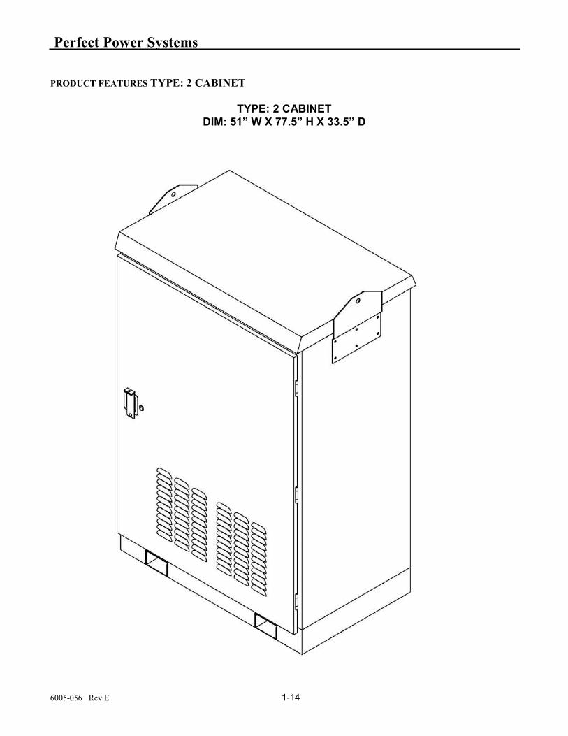
PRODUCT FEATURES TYPE: 2 CABINET
TYPE: 2 CABINET
DIM: 51” W X 77.5” H X 33.5” D

Perfect Power Systems
6005-056 Rev E 1-15
PRODUCT FEATURES TYPE: 2 CABINET

Perfect Power Systems
6005-056 Rev E 1-16
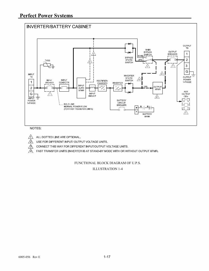
1-4 FUNCTIONAL DESCRIPTIONS
Illustration 1-4 is a simplified block diagram of the HE. This diagram provides an excellent tool in identifying the major building blocks within the HE.
1. Main input circuit breaker (CB1) - The main input circuit power provides over-current protection to the input side of the HE.
2. Input Contactor (K1) - The microprocessor based control circuitry: - verifies UPS to be normal condition and not the one “at fault”. - verifies correct input voltage and frequency to be within acceptable range and commands the closure of this contactor via control transformer T2 and fuse F1.
3. Input Chokes (L1, L3) - They act as a filter and an important circuitry of an up chopper, boosting input voltage to a higher internal DC bus voltage.
4. Battery charger - The battery charger converts AC power into regulated DC power to charge and to maintain the charge on the battery bank. The charger is fully automatic with a current limiting feature so that damage will not occur to the batteries in case of a charger malfunction. The charger is sized such that the batteries will be maintained at full charge even when the input voltage is at the low line limit for indefinite periods of time.
5. Battery - The battery bank, consisting of eight (8) 12 volt, VRLA batteries, provides the reserve energy to power the load when suitable AC input power is not present. The batteries are sealed, maintenance-free construction.
6. Inverter - When the AC input power is not available to power the load, the inverter converts the energy stored in the battery bank to AC power to supply the powers the load. The pulse width modulated (PWM) inverter utilizes high speed, high efficiency IGBTs for fast response, sinusoidal power.
7. DC Choke (L4) - If helps boosting battery voltage to an internal higher DC bus voltage.
8. Output AC Choke (L2) - This acts as a buck circuit component connecting high DC bus voltage to an appropriate AC output voltage.
9. Inverter Test Switch (SW2) - This switch is a manually operated switch which tests the HE and the batteries for proper operation. When the HE is running and Switch SW2 is pushed and held in, the HE will automatically transfer to battery operation. The HE will continue to run on batteries until the switch is released back to the ”normal” position (Switch is a momentary switch). When the switch is released, the HE returns to normal operation (provided input power is present).
10. Control Transformer (T2) - This transformer with fuse (F1), provides (internal housekeeping) power supply as well as 120 VAC for the coil of the input contactor. The primary of this transformer has various taps that needs to be matched with the various input voltages.
Perfect Power Systems
6005-056 Rev E 1-17
FUNCTIONAL BLOCK DIAGRAM OF U.P.S.
ILLUSTRATION 1-4

Perfect Power Systems
6005-056 Rev E 1-18
1-5 THEORY OF OPERATION After power is applied, the system is placed in STANDBY mode and a self-check starts. During this period, the system checks for the proper operation of the inverter and bypass SCRs. If a successful check is completed and verified, the system goes into the NORMAL mode. Refer to functional block diagram: illustration 1-4. Normal Mode: The input contactor is commanded to close and the input power is delivered to the step-down input transformer. A DC rectifier at the secondary side of the transformer converts AC voltage to a DC source which supplies the battery charger and the DC/AC inverter circuit. The battery charger is then activated allowing batteries to be continuously charged. The DC/AC inverter on the other hand converts the DC voltage to a Pulse-width-modulation (PWM) waveform. Finally this waveform is re-constructed and filtered back to a desired AC output. RESONSE TO INPUT POWER FAILURE: If the system controller senses a drop in input frequency of more than 2Hz ± 0.2Hz due to a facility outage or a voltage instability, it will consider as an input failure and immediately command the input contactor to open in order to isolate the system from the facility side. At the same time, the charger is turned off and the battery bank becomes a DC supply source to continue supplying the inverter circuit and maintain an uninterruptible supply to AC output. The LCD screen will display a “UPS PROBLEM” message. If the facility power returns, stabilizes and is in phase with the backup power, the system controller commands to close the input contactor and the system is back to NORMAL. If the battery voltage drops below 10% of its nominal value and the facility power remains off, the system will be into a FAILURE. The frequency change slow rate is limited to 0.1Hz per seconds. When frequency change is fast than above, the input contactor may be disconnected. UPS FAILURE. System controller will issue a FAILURE message on LCD screen if any of the following conditions happen:
• Internal failure • System overheats • Battery bank is under voltage
During a FAILURE, the system stops its backup operation with inverter SCRs are switched OFF and bypass SCRs are switched on. An alarm signal will be sent out to the remote signaling connection and interface. The system remains in this mode until power is cycled. UPS PROBLEM: System controller will issue a UPS PROBLEM message on the LCD screen if any of the following conditions happen:
• Input power failure • Output overloads
During a PROBLEM mode, inverter SCRs remain on and an alarm signal may be sent out to the remote signaling

Perfect Power Systems
6005-056 Rev E 1-19
connection and interface. The system will reset itself as soon as the problems disappear.

Perfect Power Systems
6005-056 Rev E 1-20
1-6 EX SERIES SIZING Each model of the EX Series is designed to supply a maximum load which is given by its kVA (1000’s of volt-amperes) and KW rating. It is very important that the load is within the rating of the EX Series to ensure that the connected loads will be properly supported.
Volt-amperes (VA) are the number of current in amps a device draws multiplied by the nominal voltage supplied to the device. The total kVA of all the loads to be connected to the EX Series is simply the sum of the kVA requirements of each device.
Each electrical device to be powered by the EX Series should have a specification sheet attached to it, which specifies the amount of power it requires. In addition, this information should also be listed in the manual supplied with each piece of equipment. The device’s nameplate should list the electrical requirements of the device in some or all of the following units: nominal voltage, current, VA or kVA, and watts or KW. If VA or kVA is not given, then multiply the nominal input voltage by the current shown on the nameplate. Add up the kVA requirements of each device to be powered by the EX Series.
The total load to be powered by the EX Series must not exceed its rating. If the total load is exceeded, the EX Series monitoring will sense an overload condition and a summary alarm will occur. The overload condition must be corrected by increasing the kVA rating of the EX Series.
1-7 OUTPUT LOADS The EX Series is designed to power any florescent or incandescent lighting. There are some types of loads, which require an excessive inrush current when first turned on or at other times during its operation.
The capacity of the EX Series may need to be greater than what would be estimated based on the nameplate requirements of loads previously discussed. Contact your Perfect Power Systems dealer or the factory directly if you have any questions about powering unusual loads from your EX Series.

Perfect Power Systems
6005-056 Rev E 1-21
1-8 Maintenance By-Pass Switch (Manual) “MTS”
This MTS is designed into UPS to Supply the Input Power directly to critical load through “By-Pass” position when UPS is out of Service. It is designed such that the UPS can be repaired while MTS is supplying the Power to Critical load without interruption.
MTS is “Make Before Break” type. The output of UPS should be no interrupted during switching from normal to By-pass. There will be an interruption from By-pass to Normal position because the UPS must be turned ON first.
“Warning” Prior to replacing the Inverter Heatsink Assembly (FRU) or other Components, Caution
must Taken since there is live voltage on Certain Components and Certain Areas
CAUTION
Perfect Power Systems
6005-056 Rev E 1-22
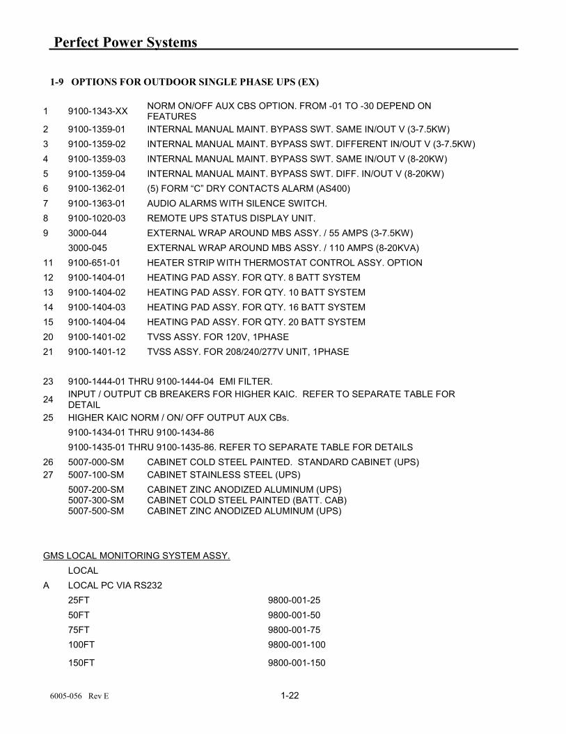
1-9 OPTIONS FOR OUTDOOR SINGLE PHASE UPS (EX)
1 9100-1343-XX NORM ON/OFF AUX CBS OPTION. FROM -01 TO -30 DEPEND ON FEATURES
2 9100-1359-01 INTERNAL MANUAL MAINT. BYPASS SWT. SAME IN/OUT V (3-7.5KW)
3 9100-1359-02 INTERNAL MANUAL MAINT. BYPASS SWT. DIFFERENT IN/OUT V (3-7.5KW)
4 9100-1359-03 INTERNAL MANUAL MAINT. BYPASS SWT. SAME IN/OUT V (8-20KW)
5 9100-1359-04 INTERNAL MANUAL MAINT. BYPASS SWT. DIFF. IN/OUT V (8-20KW)
6 9100-1362-01 (5) FORM “C” DRY CONTACTS ALARM (AS400)
7 9100-1363-01 AUDIO ALARMS WITH SILENCE SWITCH.
8 9100-1020-03 REMOTE UPS STATUS DISPLAY UNIT.
9 3000-044 EXTERNAL WRAP AROUND MBS ASSY. / 55 AMPS (3-7.5KW) 3000-045 EXTERNAL WRAP AROUND MBS ASSY. / 110 AMPS (8-20KVA)
11 9100-651-01 HEATER STRIP WITH THERMOSTAT CONTROL ASSY. OPTION
12 9100-1404-01 HEATING PAD ASSY. FOR QTY. 8 BATT SYSTEM
13 9100-1404-02 HEATING PAD ASSY. FOR QTY. 10 BATT SYSTEM
14 9100-1404-03 HEATING PAD ASSY. FOR QTY. 16 BATT SYSTEM
15 9100-1404-04 HEATING PAD ASSY. FOR QTY. 20 BATT SYSTEM
20 9100-1401-02 TVSS ASSY. FOR 120V, 1PHASE
21 9100-1401-12 TVSS ASSY. FOR 208/240/277V UNIT, 1PHASE
23 9100-1444-01 THRU 9100-1444-04 EMI FILTER.
24 INPUT / OUTPUT CB BREAKERS FOR HIGHER KAIC. REFER TO SEPARATE TABLE FOR DETAIL
25 HIGHER KAIC NORM / ON/ OFF OUTPUT AUX CBs.
9100-1434-01 THRU 9100-1434-86
9100-1435-01 THRU 9100-1435-86. REFER TO SEPARATE TABLE FOR DETAILS
26 5007-000-SM CABINET COLD STEEL PAINTED. STANDARD CABINET (UPS) 27 5007-100-SM CABINET STAINLESS STEEL (UPS)
5007-200-SM 5007-300-SM 5007-500-SM
CABINET ZINC ANODIZED ALUMINUM (UPS) CABINET COLD STEEL PAINTED (BATT. CAB) CABINET ZINC ANODIZED ALUMINUM (UPS)
GMS LOCAL MONITORING SYSTEM ASSY.
LOCAL
A LOCAL PC VIA RS232
25FT 9800-001-25
50FT 9800-001-50
75FT 9800-001-75
100FT 9800-001-100
150FT 9800-001-150

Perfect Power Systems
6005-056 Rev E 1-23
B LOCAL PC VIA RS485
150FT 9800-002-150
250FT 9800-002-250
500FT 9800-002-500
1000FT 9800-002-1000
C LOCAL EVENT LOGGING 9100-1466-01/9100-1538-XX
REMOTE
D DIAL-UP / VOICE / EVENT LOG / PAGER 9100-1467-01 (PENDING)
E DIAL-UP / DATA / FX / MAIL / EVENT LOG / PAGER
9100-1468-01 (SENSAPHONE)
F WEB / SNMP STATUS / ALARM / EVENT METERING ASSY BASIC NETAGENT SNMP ASSY ADVANCED NETAGENT SNMP ASSY ADVANCED NETAGENT SNMP W/WI-FI, HUB ASSY ADVANCED NETAGENT SNMP W/DIAL-UP MODEM ASSY ADVANCED NETAGENT SNMP W/MOBILE MODEM
9800-007-01 9800-008-01 9800-009-01 9800-010-01 9800-011-01
H AUX OUTPUT CB WITH ALARM MONITORING 1CB ASSY ANVANCED NETAGENT
9100-1453-01

Perfect Power Systems
6005-056 Rev E 1-24
1-10 SYSTEM SCHEMATIC DIAGRAM (TYP):

Perfect Power Systems
16005-056 Rev E 2-1
SECTION 2 - INSTALLATION
2-1 SITE PLANNING AND PREPARATION
The EX Series is designed for outdoor installations. These cabinets are corrosion resistant and rugged. The footprint of the EX is less than 6 square feet. Listed below are the environmental specifications for the EX Series.
Adequate clearance in the front of the equipment should be provided for service access.
OPERATING ENVIRONMENT.
AMBIENT TEMPERATURE 0° to 40° C
OPERATING ALTITUDE 1,829 M (6,000 FT) DERATE 10% FOR EACH ADDITIONAL 305 M (1,000 FT) UP TO 2,744 m (9,000 FT)
RELATIVE HUMIDITY 0% to 95% (non-condensing)
Operating the EX and batteries at either extreme of the temperature range may affect the long-term reliability of the system. This is especially true of the sealed, maintenance-free batteries. Sealed, maintenance-free batteries are designed to operate at normal room temperatures (72 to 77 °F).
STORAGE ENVIRONMENT. Provide a storage environment, which meets the following conditions:
AMBIENT TEMPERATURE -20°C to 68°C
RELATIVE HUMIDITY 0% to 95% non-condensing

Perfect Power Systems
26005-056 Rev E 2-2
2-2 CABLE ACCESS The EX Series provides cable/conduit openings in the bottom of the cabinet. Refer to Illustration 2-1 and Illustration 2-2.
TYPE: 1 CABINET (39X 74.5 X 17.0)
ILLUSTRATION 2-1

Perfect Power Systems
36005-056 Rev E 2-3
If input CB option is not included in the UPS, customer must provide I/O circuit protection.

Perfect Power Systems
46005-056 Rev E 2-4
TYPE: 2 CABINET ( 51 X 77.5 X 30.5 ) ILLUSTRATION 2-1
Note
After final installation of the unit the 2 brackets must be turned upside down by using (7/32" Tamper-Resistant Hex) tool.
Note:
To prevent moisture entering the cabinet after installation and removal of the eyebolt using 5/8-11 bolt and washer ensure the cabinet top is sealed
Perfect Power Systems
56005-056 Rev E 2-5
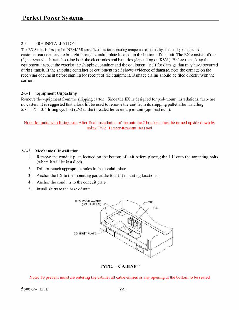
2-3 PRE-INSTALLATION The EX Series is designed to NEMA3R specifications for operating temperature, humidity, and utility voltage. All customer connections are brought through conduit plate located on the bottom of the unit. The EX consists of one (1) integrated cabinet - housing both the electronics and batteries (depending on KVA). Before unpacking the equipment, inspect the exterior the shipping container and the equipment itself for damage that may have occurred during transit. If the shipping container or equipment itself shows evidence of damage, note the damage on the receiving document before signing for receipt of the equipment. Damage claims should be filed directly with the carrier.
2-3-1 Equipment Unpacking Remove the equipment from the shipping carton. Since the EX is designed for pad-mount installations, there are no casters. It is suggested that a fork lift be used to remove the unit from its shipping pallet after installing 5/8-11 X 1-3/4 lifting eye bolt (2X) to the threaded holes on top of unit (optional item).
Note: for units with lifting ears After final installation of the unit the 2 brackets must be turned upside down by
using (7/32" Tamper-Resistant Hex) tool
2-3-2 Mechanical Installation
1. Remove the conduit plate located on the bottom of unit before placing the HU onto the mounting bolts (where it will be installed).
2. Drill or punch appropriate holes in the conduit plate.
3. Anchor the EX to the mounting pad at the four (4) mounting locations.
4. Anchor the conduits to the conduit plate.
5. Install skirts to the base of unit.
TYPE: 1 CABINET
Note: To prevent moisture entering the cabinet all cable entries or any opening at the bottom to be sealed

Perfect Power Systems
66005-056 Rev E 2-6
TYPE: 2 CABINET
Note: To prevent moisture entering the cabinet all cable entries or any opening at the bottom to be sealed.

Perfect Power Systems
76005-056 Rev E 2-7
TYPE: 2 CABINET
2-4 ELECTRICAL CONNECTIONS
CAUTION
Verify that all customer-supplied wiring is de-energized before performing any electrical work,
CAUTION
Even when the EX is off, there are potentially dangerous voltages within the EX due to the batteries. Extreme care must be taken when working within the EX enclosure.
1. Verify that the main input circuit breaker, battery circuit breaker, and output circuit breaker(s), if provided are in the ”OFF” position. See illustration 1-2 for the locations of the circuit breakers.
2. Verify BY Switch is on Normal Position. (Internal maintenance bypass option)
3. Run the power wires up through the center area of the EX. Exercise care when working around the battery area.
4. Refer to Section 1-4 for various different installation configurations.
5. Connect the input wires to the input terminal block, TB1. Three (3) wires total: ”hot”, neutral (or Hot), and ground.
6. Connect the output wires to the output terminal block, TB2. Three (3) wires total: ”hot”, neutral (or Hot), and ground.
7. This concludes the electrical connections.
Do not apply power to the EX at this time.

Perfect Power Systems
86005-056 Rev E 2-8

Perfect Power Systems
96005-056 Rev E 2-9
2-5 CUSTOMERS CONNECTIONS REFER TO PAGE 2-2 (2.2 CABLE EXCCESS AREA)
REMOVE CABLE ENTRY PLATES AND PUNCH HOLES FOR A PROPER SEZE. AND USE FOR CABLE ENTRY.
REFER TO 2-5-2 FOR PROPER OUTPUT VOLTAGE CONNECTION
2-5-1 INPUT WIRINGS FOR VARIOUS INPUT VOLTAGES ARE SAME. WHEN INPUT CIRUCIT BREAKER IS USED, INPUT CB1 IS INSTALLED IN INSIDE OF THE UPS.
1
3
2
CB1INPUT
TB1
CUSTOMERWIRESTO CB1
PROTECTOR CUSTOMER'S CONNECTION TERMINAL BLOCKILLUSTRATION 1-6
GND GND
1 2 3 1 2 31 2 3 4
HOT HOT HOT HOT GND
NNL1 L2
(+) (-)
INPUT TB1
TO CUSTOMER'S LOAD
OUTPUT TB2 BATT. CONN. TB3
FROM EXTERNAL BATT. CAB.
PROTECTOR CUSTOMER'S CONNECTION TERMINAL BLOCKILLUSTRATION 1-5

Perfect Power Systems
106005-056 Rev E 2-10
2-5-2 OUTPUT WIRING
2-5-2-1 120V IN/OUTPUT UNIT
2-5-2-2 208V IN/OUTPUT UNIT
2-5-2-3 240V IN/OUTPUT UNIT
2-5-2-4 277V IN/OUTPUT UNIT
1
2
3
4
TB2
GND
H
N
N/C
120V
1
2
3
4
TB2
GND
L2
L1
N/C
208V
1
2
3
4
TB2
GND
L2
L1
N/C
240V
1
2
3
4
TB2
GND
L1
N277V

Perfect Power Systems
116005-056 Rev E 2-11
2-5-2-5 MULTIPLE OUTPUT 240 / 120V OUTPUT UNIT
2-5-2-6 MULTIPLE OUTPUT 120 / 277V OUTPUT UNIT
2-5-2-7 MULTIPLE OUTPUT 120 / 208V OUTPUT UNIT
1
2
3
4
TB2
GND
N
L1
L2
240V
120V
120V
1
2
3
4
TB2
GND
L2
L1
277V
120V
1
2
3
4
TB2
L2
L1
L3
208V
120V
Perfect Power Systems
126005-056 Rev E 2-12
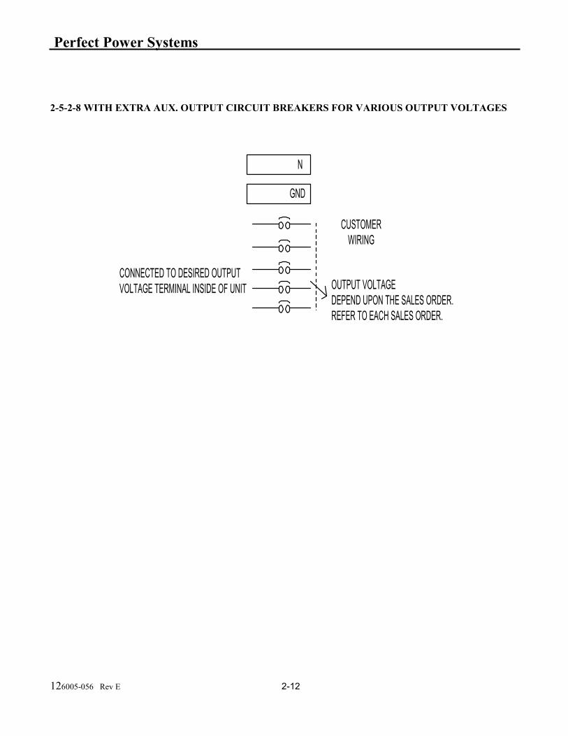
2-5-2-8 WITH EXTRA AUX. OUTPUT CIRCUIT BREAKERS FOR VARIOUS OUTPUT VOLTAGES
N
OUTPUT VOLTAGEDEPEND UPON THE SALES ORDER.REFER TO EACH SALES ORDER.
CUSTOMERWIRING
GND
CONNECTED TO DESIRED OUTPUTVOLTAGE TERMINAL INSIDE OF UNIT

Perfect Power Systems
136005-056 Rev E 2-13
2-5-3 Remote Signaling Connections
The EX includes the feature of providing dry relay contacts for remote signaling capabilities. Signals available for remote annunciation are:
”UTILITY FAILURE” - This is a normally open contact, which closes upon loss of input power to the EX.
”LOW BATTERY” - This is a normally open contact, which closes when the EX is on battery operation and the batteries are approaching complete discharge.
”ON INVERTER or ON BYPASS” - This is a normally open contact, which closes when the EX goes to battery operation.
”SUMMARY ALARM” - This is a normally open contact, which closed when the EX has any one of the alarm condition.
If there are no requirements for remote signaling, section 2-5-3 may be skipped.
1. The dry relay contacts for remote signaling are provided via connector (P2) of control board (A2) located on the right door inside of the EX. See illustration 1-2 for locations of Control Board.
2. The dry relay contacts have the following maximum ratings: 125 volts (AC or DC) maximum 1.25 amperes maximum 30 watts / 50 VA maximum It is imperative that the relay contact ratings are not exceeded. Otherwise, damage to the relays within the EX will occur.
3. Determine which signals will be used. Connect wires (customer-supplied) to the connector.
4. This concludes the remote signaling connection procedures.
5. This concludes the installation procedures. Please proceed to Section 3 - Start-Up for the steps necessary to start-up the EX.
2-6 STORAGE The EX Series can be placed in storage while not in use. Provide a protected environment, which meets the environmental parameters listed below.
AMBIENT TEMPERATURE -4° to 140°F -20° to 60°C
RELATIVE HUMIDITY 0% to 95% non-condensing
If the EX Series will be stored for several months or longer, it should be serviced by charging the batteries for 24 hours at regular, three-month intervals. While in storage, service the unit using the procedures in this section.

Perfect Power Systems
146005-056 Rev E 2-14
During long-term storage, the batteries are subject to aging and deterioration. If after visual inspection, the batteries need to be replaced contact your Perfect Power Systems dealer or the Perfect Power Systems factory directly to obtain new batteries.
If the UPS is stored in its original packaging, unpack UPS using unpacking procedures outlined in
Section 2-3-1.
If the UPS is not connected to a source of power, first connect the UPS to an appropriate source of power using the procedures in Section 2-4, Electrical Connections.
When the UPS is unpacked and first connected to an AC power source, recharge batteries as follows:
1. Unlock and open front doors.
2. Visually inspect batteries for signs of deterioration and leakage. Replace batteries if required.
3. Set AC power source to ON.
4. Close input CB, if provided (CB1)
5. Close battery CB, if provided (CB2)
6. The UPS automatically recharges batteries. The LCD panel will indicate the battery voltage and charging current.
7. Allow UPS to run for 24 hours to fully charge batteries.
When batteries have reached partial charge, the battery charging current will be under 1 Amps on LCD panel.
8. Turn OFF input power to the UPS.
9. Close and lock front door.

Perfect Power Systems
6005-056 Rev E 3-1
SECTION 3 - OPERATION
3-1 START-UP PROCEDURES 1. Verify that the main input circuit breaker, battery breaker, and output circuit breaker(s), if provided, are in
the ”OFF” or ”down” positions. Maintenance By Pass Switch is on Normal Position.
Refer to illustration 1-2 for the locations of the circuit breakers.
CAUTION
If during the start-up procedures anything unusual occurs, immediately turn off the input circuit breaker, and contact Perfect Power Systems at (800) 797-7782 for technical assistance. Also, use this number for other question or additional information.
2. Apply input power to the EX.
Verify that the voltage appearing on the input terminal block is same as on nameplate
Verify that there are no voltages appearing on the output terminal block.
3. Turn on the main input circuit breaker CB1.
4. After turning on the System, wait one (1) minute while the EX runs through its internal diagnostic routines.
Hear the sound of contactor closing.
See the fan(s) running.
See the LCD panel displaying correct messages. See Appendix A for LCD displays.
Verify that the LCD display panel indicates all correct parameters - see Appendix A for details. Verify that the output voltage is 120/the nameplate.
5. Close battery breaker (CB2) in the UPS cabinet.
6. At this point in time, the EX should be operating as Normal. If the EX is not operating in the normal mode, turn off the input circuit breaker (CB1). Request for technical assistance. Refer to LCD display in Appendix A.
3-1 START-UP PROCEDURES (continued) If LCD display shows Normal, then
7. Recheck that the output voltage is same as in the nameplate On LCD Display.

Perfect Power Systems
6005-056 Rev E 3-2
If the output voltage is approximately same as nameplate, turn on the loads, which will be powered from the EX Series.
8. The next steps verify battery operation and the inverter test switch.
To place the EX in battery operation (to simulate loss of input power), press and hold yellow Inverter Test Switch. With switch in the hold position, the EX should be running on its internal batteries.
Verify that the LCD panel displays such.
Verify that the ”Battery Charger” is OFF in LCD panel.
Note: Be sure to release the switch, after the test, so it will not deplete the batteries.
9. The EX is now fully functional - providing clean, sine wave power to the load with battery back up in case of an input power failure. This concludes the start-up procedures.
3-2 OPERATIONS
3-2-1 Turning On the EX
Make sure that all Circuit Breakers are in OFF position 1. Apply input power.
2. With input power available, turn on the main input circuit breaker, CB1 (if provided).
3. Close battery breaker (CB2), only after the LCD display is lit & displays screens per Appendix A.
4. Wait till you hear the input contactor closing and fan running.
5. Verify that all parameters on LCD display panel are proper. See Appendix A for display details.
6. Close the output circuit breaker.
3-2-2 Turning off the EX:
(A) If the Maintenance By pass switch is on Normal position and MTS is not being used, then, verify that SI switch is at OFF position. 1. Turn off the Battery Breaker.
2. Turn off the Input Breaker.

Perfect Power Systems
6005-056 Rev E 3-3
(B) If using “MTS” Switch you need to switch SI to on position first and switch “MTS” (Maintenance By-Pass Switch) to By-Pass position first, (do not turn off output CB’s)
1. Turn off the Battery Breaker.
2. Turn off the Input Breaker.
WARNING LIVE HIGH VOLTAGE WILL BE PRESENT AT VARIOUS COMPONENTS EVEN AFTER INPUT
AND BATTERY CB ARE OFF

Perfect Power Systems
6005-056 Rev E 3-4
3-3 RENEWAL PARTS
On the following pages are pictorials of the parts location in the EX. The page after the pictorials is a chart of the part numbers for each part by the size or voltage of the particular EX that requires parts.

Perfect Power Systems
6005-056 Rev E 3-5
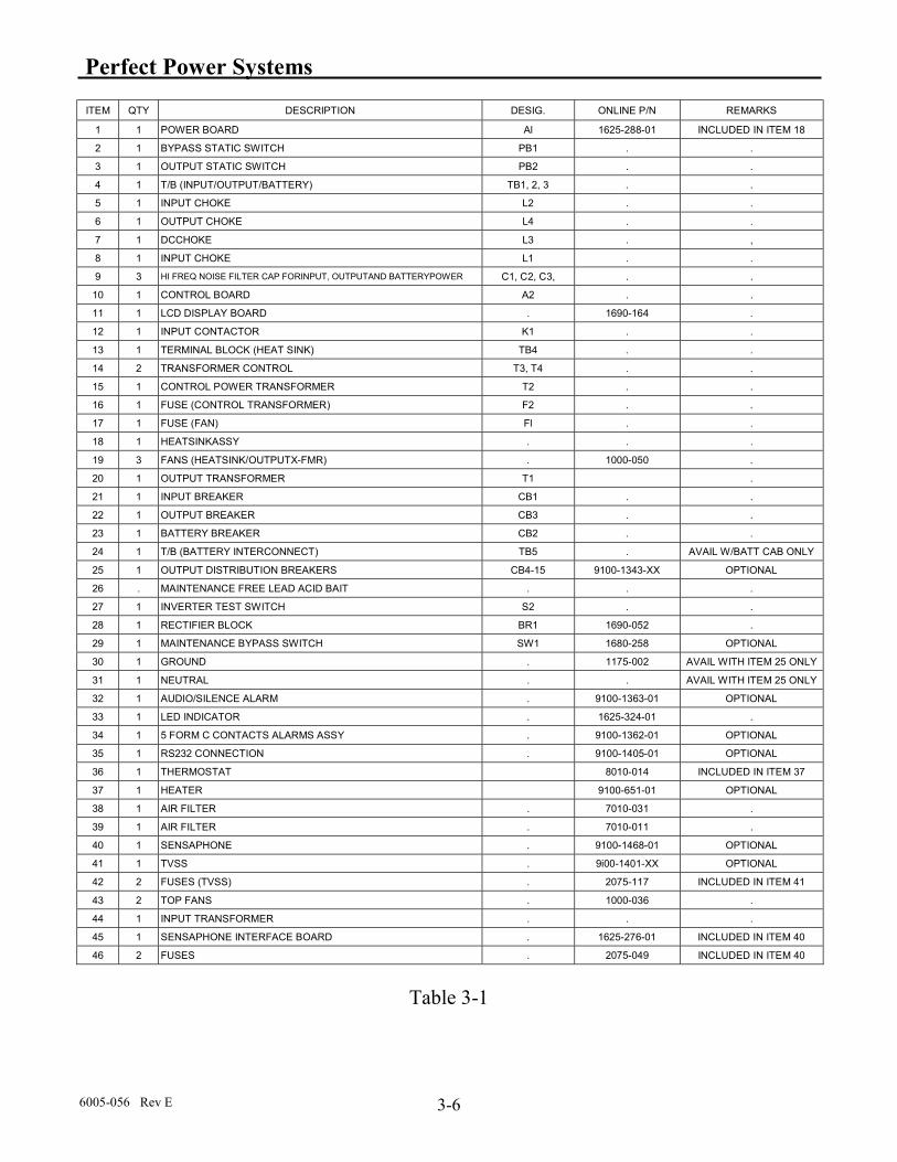
Perfect Power Systems
6005-056 Rev E 3-6
ITEM QTY DESCRIPTION DESIG. ONLINE P/N REMARKS
1 1 POWER BOARD Al 1625-288-01 INCLUDED IN ITEM 18
2 1 BYPASS STATIC SWITCH PB1 . .
3 1 OUTPUT STATIC SWITCH PB2 . .
4 1 T/B (INPUT/OUTPUT/BATTERY) TB1, 2, 3 . .
5 1 INPUT CHOKE L2 . .
6 1 OUTPUT CHOKE L4 . .
7 1 DCCHOKE L3 . ,
8 1 INPUT CHOKE L1 . .
9 3 HI FREQ NOISE FILTER CAP FORINPUT, OUTPUTAND BATTERYPOWER C1, C2, C3, . .
10 1 CONTROL BOARD A2 . .
11 1 LCD DISPLAY BOARD . 1690-164 .
12 1 INPUT CONTACTOR K1 . .
13 1 TERMINAL BLOCK (HEAT SINK) TB4 . .
14 2 TRANSFORMER CONTROL T3, T4 . .
15 1 CONTROL POWER TRANSFORMER T2 . .
16 1 FUSE (CONTROL TRANSFORMER) F2 . .
17 1 FUSE (FAN) Fl . .
18 1 HEATSINKASSY . . .
19 3 FANS (HEATSINK/OUTPUTX-FMR) . 1000-050 .
20 1 OUTPUT TRANSFORMER T1 .
21 1 INPUT BREAKER CB1 . .
22 1 OUTPUT BREAKER CB3 . .
23 1 BATTERY BREAKER CB2 . .
24 1 T/B (BATTERY INTERCONNECT) TB5 . AVAIL W/BATT CAB ONLY
25 1 OUTPUT DISTRIBUTION BREAKERS CB4-15 9100-1343-XX OPTIONAL
26 . MAINTENANCE FREE LEAD ACID BAIT . . .
27 1 INVERTER TEST SWITCH S2 . .
28 1 RECTIFIER BLOCK BR1 1690-052 .
29 1 MAINTENANCE BYPASS SWITCH SW1 1680-258 OPTIONAL
30 1 GROUND . 1175-002 AVAIL WITH ITEM 25 ONLY
31 1 NEUTRAL . . AVAIL WITH ITEM 25 ONLY
32 1 AUDIO/SILENCE ALARM . 9100-1363-01 OPTIONAL
33 1 LED INDICATOR . 1625-324-01 .
34 1 5 FORM C CONTACTS ALARMS ASSY . 9100-1362-01 OPTIONAL
35 1 RS232 CONNECTION . 9100-1405-01 OPTIONAL
36 1 THERMOSTAT 8010-014 INCLUDED IN ITEM 37
37 1 HEATER 9100-651-01 OPTIONAL
38 1 AIR FILTER . 7010-031 .
39 1 AIR FILTER . 7010-011 .
40 1 SENSAPHONE . 9100-1468-01 OPTIONAL
41 1 TVSS . 9i00-1401-XX OPTIONAL
42 2 FUSES (TVSS) . 2075-117 INCLUDED IN ITEM 41
43 2 TOP FANS . 1000-036 .
44 1 INPUT TRANSFORMER . . .
45 1 SENSAPHONE INTERFACE BOARD . 1625-276-01 INCLUDED IN ITEM 40
46 2 FUSES . 2075-049 INCLUDED IN ITEM 40
Table 3-1

Perfect Power Systems
6005-056 Rev E 3-7
3-4 FIELD REPLACEABLE UNITS (FRUs) Refer to Table 3-1 for ordering the renewed parts from the factory. Supply the information from the nameplate of the unit, such as serial number, model number, KVA, P.F., input/output battery voltages, and date of manufacture, when ordering parts from factory. Call Toll Free (800) PWR-SRVC in North America. Qualified factory trained service personnel should only replace these parts.
3-4-1 Control Board This board is located on the right door at top and mounted at 4 corners with nuts and washers. Verify that all connectors are marked with their designations and pin #1, 2, etc.... Unplug P1, P3, P4, P5, P7, P11, P12. Install new board. Reconnect all above connector into their correct designations and orientation.
3-4-2 All Other Parts Verify that the cables are marked before disconnecting. Replace the part with the new part. Reconnect wiring same way as it was disconnected.
3-4-3 Heat Sink Assembly Replacement Procedure
Note: Verify that the MTS is on By-Pass Position and SI is at ON position
1. The heat sink assembly is located on the right side of the top electronic shelf, inside the UPS cabinet. See Illustration 3-2 for details. Verify that all cables and connectors has label or identify as shown. This is important for reinstalling the assembly. Disconnect connectors P7, P6, P4, P1 from the top side of the main big PWBD, A1, (1625-287-01) which is sitting horizontally on the big black heat sink.
2. Disconnect 5 power cables at TB4-1 through TB4-5 using flat screw driver. Verify and install label id for each cable before disconnecting.
3. Disconnect power cables at PB2-2, PB2-1, PB1-1, and PB1-2 from the front side of the assembly. Watch for small copper plate coming out from front and rear of the power boards for reinstalling.
4. Disconnect 2 small connector from front at PB2 and PB1. They should be labeled A3-P1 and A4-P1 respectively.
5. Remove the jumper from PB2-1 to PB1-1, if installed.
6. Remove 3 phillips screws at front holding heat sink bracket. Pull the complete assembly forward and up. Remove it from tray gently, verifying that no cables or wires are latching up. See illustration 3-3.
7. Install new assembly in the reverse order. Note that the rear bracket attached to the heat sink slides under the bracket secured on to the back panel. Slide the assembly back and reinstall 3 phillips screws.
8. Reinstall all the cables and connectors in the reverse order. Verify with illustration 3-2.
9. Visually inspect connections prior to starting up the unit.

Perfect Power Systems
6005-056 Rev E 3-8
3-4 Field Replaceable Units (FRUs) (continued)
PB1-2 P6
P4
P7
Phase C (Q3/Q4)
TB4 Phase A (Q1/Q2)
Phase B (Q5/Q6)
E1/C2 (Q7/Q8)
E2 (Q7/Q8)
P1
A3-P1(RED)
A4-P1(RED)
A3-P1(WHITE)
A4-P1(WHITE)
PB1-1
PB2-1
PB2-2
J61 2 3 4
J41 2
BLKRED
J71 2
BLKRED
HEAT SINK ASSEMBLY ILLUSTRATION 3-2

Perfect Power Systems
6005-056 Rev E 3-9
3-4 Field Replaceable Units (FRUs) (continued)
REMOVAL OF HEAT SINK ASSEMBLY (SIMPLIFIED) ILLUSTRATION 3-3

Perfect Power Systems
6005-056 Rev E 4-1
SECTION 4: BATTERY MAINTENANCE
4.1 INTRODUCTION The battery is a component that degrades with time in service. The Cell/Unit internal resistance impedance will increase. The actual life achieved will be a function not only of the Battery design but also of the Application. To achieve the optimum life of the battery and avoid problems Battery Maintenance should be considered.
Battery Maintenance Testing & Specifications
Battery Specifications • Float Voltage - The specified float voltage “wind “is.2.25 ~ 2.30 V.P.C. @ 25°C.This Value will
help in reducing recharge times and keeping the batteries at the highest state of charge. • Recommended Procedures
These methods are designed to be used on a battery system installed for a minimum period of 6 month, in a steady state of Float condition and not under conditions of high current recharge or discharge.
• Measure Float Voltage • When the battery voltage is low over 24 hours test system, remove the Battery. • Measure and record system voltage directly across the battery circuit breaker. • If the battery system is determined to be low voltage system after 24 hours of charging the system voltage
will be only 3% low, remove and replace the Battery. • Battery Servicing • Measure and record a 10% sample of individual battery temperatures at the negative terminal post. • Identify batteries that are greater than 3° C above ambient from the calculated average. If no external causes
for higher battery temperatures are noted. • Check that the filters are clean and Fans are operational. • If no change is noted, remove and replace the Battery.
If no change is noted, remove and replace the Battery. Visual Inspections.
Perfect Power Systems
6005-056 Rev E 4-2
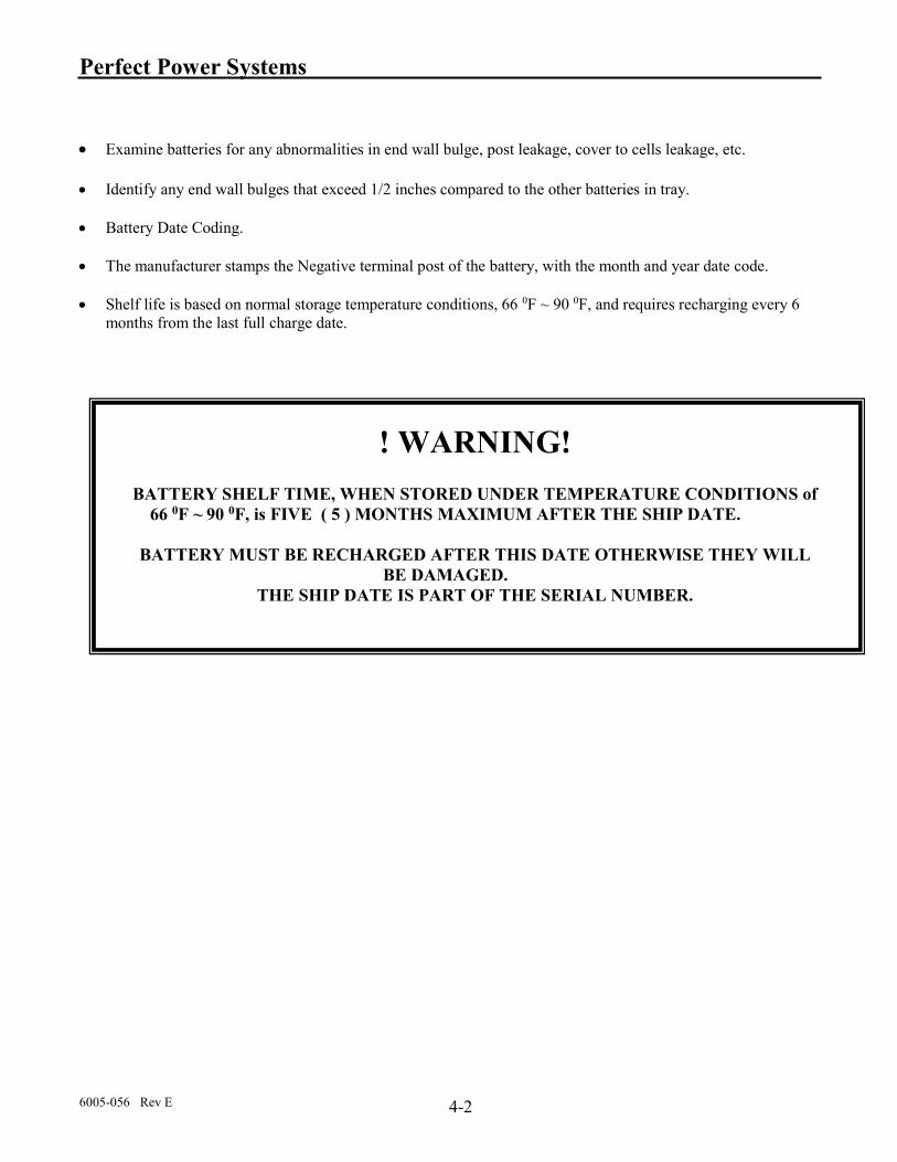
Examine batteries for any abnormalities in end wall bulge, post leakage, cover to cells leakage, etc.
Identify any end wall bulges that exceed 1/2 inches compared to the other batteries in tray. Battery Date Coding. The manufacturer stamps the Negative terminal post of the battery, with the month and year date code. Shelf life is based on normal storage temperature conditions, 66 0F ~ 90 0F, and requires recharging every 6
months from the last full charge date.
! WARNING!
BATTERY SHELF TIME, WHEN STORED UNDER TEMPERATURE CONDITIONS of 66 0F ~ 90 0F, is FIVE ( 5 ) MONTHS MAXIMUM AFTER THE SHIP DATE.
BATTERY MUST BE RECHARGED AFTER THIS DATE OTHERWISE THEY WILL
BE DAMAGED. THE SHIP DATE IS PART OF THE SERIAL NUMBER.

Perfect Power Systems
6005-056 Rev E A-1
APENDIX A - SPECIFICATIONS
SPECIFICATIONS FOR KVA, 0.7PF UNITS
POWER RATING (KVA) 3 / 2.1 5 / 3.5 7.5 / 5.25 10 / 7 12.5 / 8.75 15 / 10.5 20 / 15
INPUT VOLTAGE (VAC) Single Phase,
120/208/240/277 VAC Single Phase, 208/240/277 VAC
MAXIMUM CURRENT 29/17/15/13 44/25/22/19 36/30/26 74/40/35 57/49/43 68/59/51
TOLERANCE +15% to -15%
FREQUENCY (Hz) 60 +/- 3%
POWER FACTOR 0.98 to 1.0 (Typical)
OVERCURRENT PROTECTION Electronic / Circuit Breaker
NUMBER OF WIRES 2 Wires plus Ground
POWER CONNECTION Hard Wired (Terminal Block)
OUTPUT RATING (KVA/KW) 3 / 2.1 5 / 3.5 7.5 / 5.25 10 / 7 12.5 / 8.75 15 / 10.5 20/15
VOLTAGE (VAC) Single Phase, 120/208/240/277 VAC
VOLTAGE REGULATION +/-3% No Load to Full Load; +/-3% High Line to Low Line
FREQUENCY (Hz) 60 Hz +/-0.25 Hz (When on Inverter)
WAVESHAPE Sine Wave
HARMONIC DISTORTION <5% THD; <3% Single Harmonic
CREST FACTOR Up to 3 to 1
POWER FACTOR 0.65 Lagging or Leading to Unity
STEADY-STATE CURRENT 18/10/9/8 29/17/15/13 44/25/22/19 58/34/29/25 73/4236/32 88/50/44/38
OVERLOAD 125 % for One (1) minutes, surge 150 %
PROTECTION Electronic / Circuit Breaker
NOISE REJECTION -120 dB Common Mode; -60 dB Normal Mode
NUMBER OF WIRES 2 Wires plus Ground
POWER CONNECTION Hard Wired (Terminal Block)

Perfect Power Systems
6005-056 Rev E A-2
POWER RATING (KVA) 3 / 2.1 5 / 3.5 7.5 / 5.25 10 / 7 12.5 / 8.75 15 / 10.5 20 / 15
BATTBATTERY BATTERY RUN TIME 90 Minutes Minimum
BATTERY TYPE Sealed, Maintenance-Free, AGM, VRLA type
NOMINAL DC VOLTAGE 96 VDC 120 VDC 120 VDC 192 VDC 192 VDC 240 VDC
OVERCURRENT PROTECTION Circuit Breaker
PACKAGING Batteries Housed in Same Enclosure and/or additional battery cabinet (See Table 2-1)
MONITORING AND COMMUNICATIONS LCD SCREEN Input Voltage; Battery Charger; UPS Output; On Battery; Low Battery; Summary Alarm
INDICATORS LCD Display Panel
RELAY INTERFACE Dry Contacts for: UPS On (N.C.); On Inverter (N.O.); Loss of Input Power (N.O.); Low Battery (N.O.)
CONTACT RATING 125 Volts (AC or DC) Maximum; 1.25 Amperes Maximum; 30 Watts / 50 VA Maximum
INTERFACE CONNECTION Hard Wired (Terminal Block)
ENVIRONMENTAL USRGE WITHSTANDABILITY ANSI C62.41-1980 Categories A & B
OPERATING TEMPERATURE Meets NEMA Requirements
OPERATING RELATIVE HUMIDITY 0 to 95% Non-Condensing
ALTITUDE Up to 6,000 Feet (1,829 Meters) with No De-Rating
COOLING Air Cooled-Forced Fan
PHYSICAL SIZE H x W x D in. (cm) 70 x 39 x 20 (177.8 x 99.1 x 50.8)
WEIGHT lbs (kg) with batteries 600 (273) 900 (409) 1150 (523) 1600 (727)
1850 (841) 2250 (1023)
CONSTRUCTION Painted Steel Enclosure with 3 Point Double Locking Front Door; and Full-Length Door Hinge.
ENCLOSURE Designed for Inside Installations
COLOR Natural finish
ACCESSIBILITY Front - All Servicing is Through the Front; No Side or Rear Access is Required.
CABLE ENTRY Bottom or sides
MOUNTING Four (4) Holes Provided to Anchor Enclosure to Pedestal (Supplied by Others)

Perfect Power Systems
6005-056 Rev E A-3
SPECIFICATIONS FOR KW, 1.0PF UNITS
POWER RATING (KW) 3 / 3 5 / 5 6 / 6 7.5 / 7.5 8 / 8 10 / 10 12.5 /
12.5
15 / 15
20 / 14
INPUT VOLTAGE (VAC) Single Phase,
120/208/240/277 VAC 208/240/277
VAC 120/208/240
/277 VAC
Single Phase,
208/240/277 VAC
MAXIMUM CURRENT 40/23/20/17 60/35/30/26 69/42/36/31 51/41/36 78/45/39/40 64/56/48 79/69/59 95/83/71
TOLERANCE +15% to -15%
FREQUENCY (Hz) 60 +/- 3%
POWER FACTOR 0.98 to 1.0 (Typical)
OVERCURRENT PROTECTION Electronic / Circuit Breaker
NUMBER OF WIRES 2 Wires plus Ground
POWER CONNECTION Hard Wired (Terminal Block)
OUTPUT RATING (KVA/KW) 3 / 3 5 / 5 6 / 6 7.5 / 7.5 8 / 8 10 / 10 12.5 / 12.5 15 / 15
VOLTAGE(VAC) Single Phase, 120/208/240/277 VAC
VOLTAGE REGULATION +/-3% No Load to Full Load; +/-3% High Line to Low Line
FREQUENCY (Hz) 60 Hz +/-0.25 Hz (When on Inverter)
WAVESHAPE Sine Wave
HARMONIC DISTORTION <5% THD; <3% Single Harmonic
CREST FACTOR Up to 3 to 1
POWER FACTOR 0.65 Lagging or Leading to Unity
STEADY-STATE CURRENT (Normal Mode / Emergency Mode)
25/14/13/11 42/24/21/18 50/29/25/22 63/36/31/27 66/38/34/28 83/48/42/36 104/60/52/45 125/72/63/54
OVERLOAD 125 % for One (1) minutes, surge 150 %
PROTECTION Electronic / Circuit Breaker
NOISE REJECTION -120 dB Common Mode; -60 dB Normal Mode
NUMBER OF WIRES 2 Wires plus Ground
POWER CONNECTION Hard Wired (Terminal Block)

Perfect Power Systems
6005-056 Rev E A-4
POWER RATING (KW) 3 / 3 5 / 5 6 / 6 7.5 / 7.5 8 / 8 10 / 10 12.5 /
12.5
15 / 15
20 / 14
INPUT VOLTAGE (VAC) Single Phase, 120/208/240/277 VAC Single Phase, 208/240/277 VAC
MAXIMUM CURRENT 40/23/20/17 60/35/30/26 51/41/36 64/56/48 79/69/59 95/83/71
TOLERANCE +15% to -15%
FREQUENCY (Hz) 60 +/- 3%
POWER FACTOR 0.98 to 1.0 (Typical)
OVERCURRENT PROTECTION Electronic / Circuit Breaker
NUMBER OF WIRES 2 Wires plus Ground
POWER CONNECTION Hard Wired (Terminal Block)
OUTPUT RATING (KVA/KW) 3 / 3 5 / 5 6 / 6 7.5 / 7.5 8 / 8 10 / 10 12.5 / 12.5 15 / 15
VOLTAGE(VAC) Single Phase, 120/208/240/277 VAC
VOLTAGE REGULATION +/-3% No Load to Full Load; +/-3% High Line to Low Line
FREQUENCY (Hz) 60 Hz +/-0.25 Hz (When on Inverter)
WAVESHAPE Sine Wave
HARMONIC DISTORTION <5% THD; <3% Single Harmonic
CREST FACTOR Up to 3 to 1
POWER FACTOR 0.65 Lagging or Leading to Unity
STEADY-STATE CURRENT (Normal Mode / Emergency Mode)
25/14/13/11 42/24/21/18 63/36/31/27 83/48/42/36 104/60/52/45 125/72/63/54
OVERLOAD 125 % for One (1) minutes, surge 150 %
PROTECTION Electronic / Circuit Breaker
NOISE REJECTION -120 dB Common Mode; -60 dB Normal Mode
NUMBER OF WIRES 2 Wires plus Ground
POWER CONNECTION Hard Wired (Terminal Block)

Perfect Power Systems
6005-056 Rev E B-1
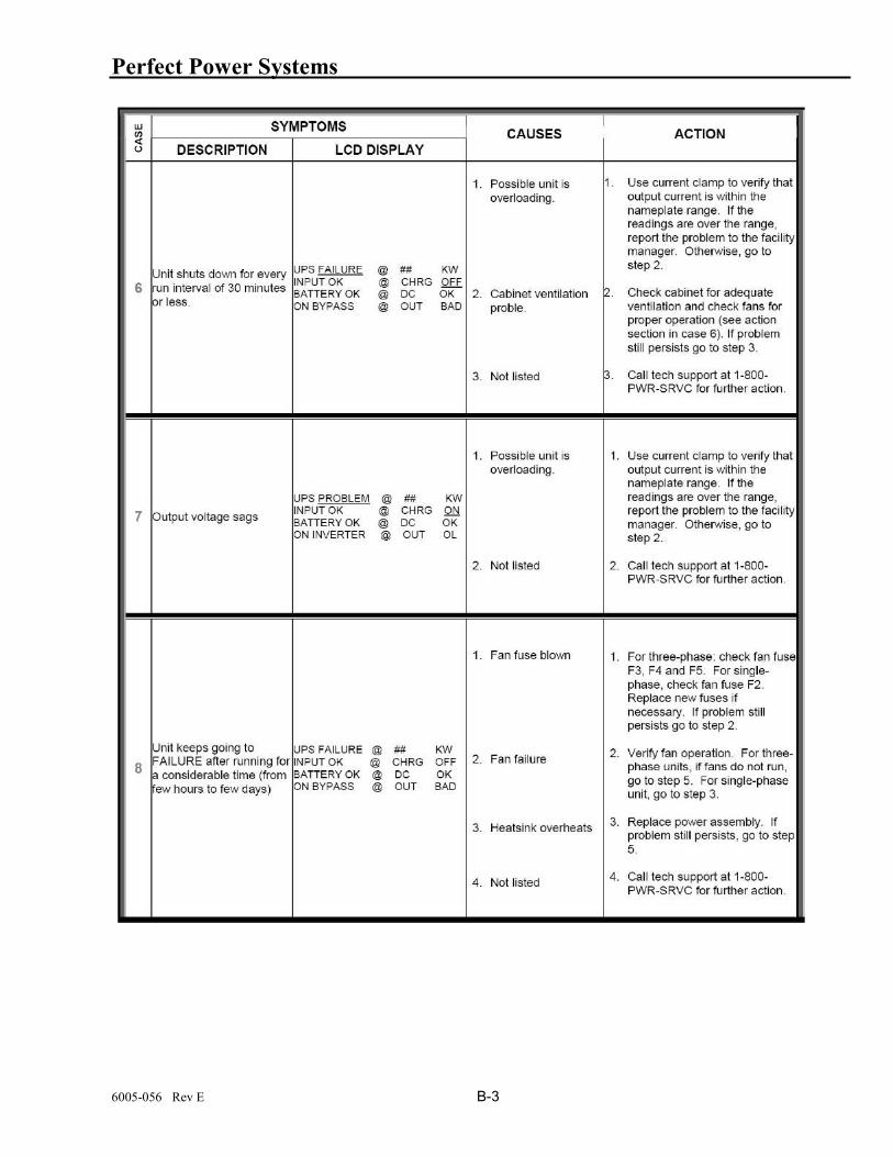
APPENDIX B – TROUBLE SHOOTING GUIDE & SYSTEM ALARMS

Perfect Power Systems
6005-056 Rev E B-2
Perfect Power Systems
6005-056 Rev E B-3

Perfect Power Systems
6005-056 Rev E B-4

Perfect Power Systems
005-056 Rev E C1
APPENDIX C – OPTIONAL MAIN INPUT & MAIN OUTPUT BREAKERS FOR VARIOUS MODELS.
(*All values are typical as reference only)