9 · 2017-06-27 · tender document - water supply system for iim udaipur. volume 2 -1- technical...
TRANSCRIPT

_______________________________________________________________________________________________
TENDER DOCUMENT - WATER SUPPLY SYSTEM FOR IIM UDAIPUR. VOLUME 2
-1-
TECHNICAL SPECIFICATIONS
TENDER DOCUMENT -
SUPPLY INSTALLATION, TESTING & COMMISSIONING OF HYDROPNEUMATIC SYSTEMS, WTP, PUMPS, VALVES & FLOW METERS WORKS
FOR PERMANENT CAMPUS (PHASE I) FOR
INDIAN INSTITUTE OF MANAGEMENT UDAIPUR, AT VILLAGE BALICHA, UDAIPUR.
Item 1.0 : Hydro-pneumatic system

_______________________________________________________________________________________________
TENDER DOCUMENT - WATER SUPPLY SYSTEM FOR IIM UDAIPUR. VOLUME 2
-2-
Supply, installation, testing & commissioning of Hydro-pneumatic system with vertical inline Multistage booster centrifugal SS - 316L pump-motor sets, suitable for operation on 415 volts, 50 Hz, 3 phase AC supply, with 500 Ltrs pneumatic balancing tank, mounting skid, foot valves, G.I. suction & discharge pipes, fittings, cast brass / virgin brass valves, C.I. Strainers ar suction head, etc. Each pump shall have TEFC 1450 / 2900 RPM three phase electric motor. The scope includes pressure switches, VFD based control panel with starters, protections, relays, cables, interlocking with level & pressure switches. Suction / Delivery Piping all connections, etc complete for domestic supply only. Panel to be compatible to MODBUS IP, with the adequate I/O. SCOPE (Item Description)
The item includes the Pumps (Vertical/Horizontal centrifugal type), Pressure vessels, pressure switches, gauges, pressure transmitter on delivery manifold, pump suction & delivery piping, manifolds & valves, flexible bellows, Fixed speed/ variable frequency drive, control panels, Microprocessor based operation) and all accessories including installation, testing & commissioning.
PUMP-MOTOR SET
DESIGN & CONSTRUCTION FEATURES
Two types of pumps i.e. inline vertical multistage or horizontal type centrifugal pump shall be provided. Variable frequency drive shall be provided with one of the installed pump – if specified in Schedule of quantity.
The pump motor set and shall be suitable for 3 Ph., 415 V, 50 Hz. AC power supply and having 1500/ 2900 RPM speed. The pump shall be installed with isolation gate/ butterfly valve, non return valve, etc. The detailed specification for pump & motor is as below :
The design and manufacture of the pump shall comply with all currently applicable statutes, regulations and safety codes in the locality where the equipment will be installed.
The pump shall be capable of developing required total head at rated capacity. Impeller shall be closed type and shall be dynamically balanced. The pump shall have non overloading characteristics.
The casing shall be of rigid construction and shall have side suction and side delivery in case of vertical multistage pump and side suction and central delivery in case of horizontal centrifugal pump.
The pump shall have very small length suction and delivery pipe connections which will result in minimum friction loss.
Impeller shall be of one piece and shall be of SS CF8 M.
The shaft shall be of S.S. and its surface shall be properly finished.
Shaft sleeves shall be provided to protect shaft from any damage.
_______________________________________________________________________________________________
TENDER DOCUMENT - WATER SUPPLY SYSTEM FOR IIM UDAIPUR. VOLUME 2
-3-
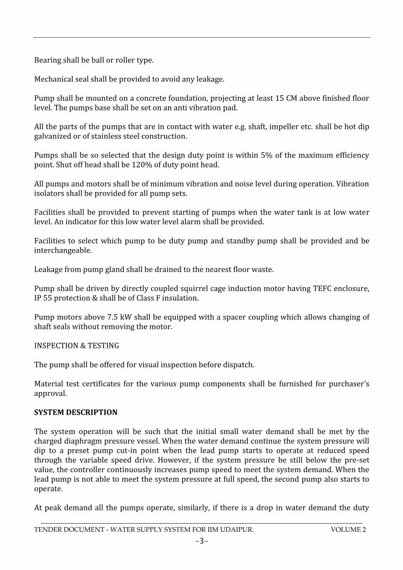
Bearing shall be ball or roller type.
Mechanical seal shall be provided to avoid any leakage.
Pump shall be mounted on a concrete foundation, projecting at least 15 CM above finished floor level. The pumps base shall be set on an anti vibration pad.
All the parts of the pumps that are in contact with water e.g. shaft, impeller etc. shall be hot dip galvanized or of stainless steel construction.
Pumps shall be so selected that the design duty point is within 5% of the maximum efficiency point. Shut off head shall be 120% of duty point head.
All pumps and motors shall be of minimum vibration and noise level during operation. Vibration isolators shall be provided for all pump sets.
Facilities shall be provided to prevent starting of pumps when the water tank is at low water level. An indicator for this low water level alarm shall be provided.
Facilities to select which pump to be duty pump and standby pump shall be provided and be interchangeable.
Leakage from pump gland shall be drained to the nearest floor waste.
Pump shall be driven by directly coupled squirrel cage induction motor having TEFC enclosure, IP 55 protection & shall be of Class F insulation.
Pump motors above 7.5 kW shall be equipped with a spacer coupling which allows changing of shaft seals without removing the motor.
INSPECTION & TESTING
The pump shall be offered for visual inspection before dispatch.
Material test certificates for the various pump components shall be furnished for purchaser’s approval.
SYSTEM DESCRIPTION
The system operation will be such that the initial small water demand shall be met by the charged diaphragm pressure vessel. When the water demand continue the system pressure will dip to a preset pump cut-in point when the lead pump starts to operate at reduced speed through the variable speed drive. However, if the system pressure be still below the pre-set value, the controller continuously increases pump speed to meet the system demand. When the lead pump is not able to meet the system pressure at full speed, the second pump also starts to operate.
At peak demand all the pumps operate, similarly, if there is a drop in water demand the duty

_______________________________________________________________________________________________
TENDER DOCUMENT - WATER SUPPLY SYSTEM FOR IIM UDAIPUR. VOLUME 2
-4-
pump speed starts to reduce, then standby pumps cuts-off, followed by stopping of the duty pump.
The closed diaphragm pressure vessel shall be of polyethylene material with a pressure gauge and isolating valve. The interior shall be of non-toxic lining suitable for use with potable water. The vessel shall be manufactured to conform to ASME pressure vessel code/ standards.
The system shall be under the control of a microprocessor based control panel.
A pressure transmitter shall detect the pressure at the delivery manifold and feedback to the microprocessor control panel via control circuit.
The system shall incorporate a frequency converter or frequency converter motors on the pumps and the pressure transmitter shall register the actual pressure on the discharge side.
The variable frequency drive pumping system shall maintain a constant pressure regardless of the system demand. If there is a drop in pressure outside the preset point, the Variable Frequency Drive (VFD) pump shall start to run until the pressure increases to the preset limit, or it will continue to increase the pump speeds to the upper limit of the frequency. If the water system demand still cannot be met, the second pump shall be called in to run, the VFD will then alter the pump speed to meet the preset pressure point. If the set point is still unable to be met, the third pump is then activated to run (in case of 3 pumps units).
This shall be achieved by continuously varying the motor speed of the duty pump according to the demand up to a maximum designed capacity.
Under decreasing hydraulic demand the reverse sequence to the above description shall apply. Alternatively pumping system shall be with fixed speed drive motor. By getting the signal from microprocessor based control panel through pressure transmitter, pumps will operate in sequence & vice a versa.
The frequency converter shall be linked to the motor of the duty pump for continuous speed adjustment and ultimately the water delivery shall be maintained at constant pressure at the pre-set value.
CONTROL PANEL
The motor control panel shall be equipped with all the necessary electrical components including a microprocessor control unit and a frequency drive. The control panel and the microprocessor shall cover the followings functions.
Flexibility and simplicity in allowing the necessary re-adjustment of the pumping system pre-set delivery pressure to operate the pumps within the specified maximum and minimum delivery ranges.
Automatic changeover of the pumps to be controlled by the microprocessor which dictates the duty and standby pumps.
When the system has not been operated for more than 24 hours, it shall automatically start the
_______________________________________________________________________________________________
TENDER DOCUMENT - WATER SUPPLY SYSTEM FOR IIM UDAIPUR. VOLUME 2
-5-
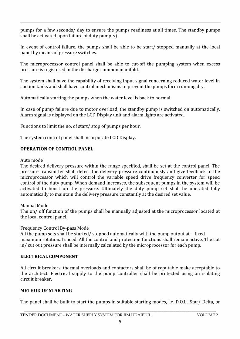
pumps for a few seconds/ day to ensure the pumps readiness at all times. The standby pumps shall be activated upon failure of duty pump(s).
In event of control failure, the pumps shall be able to be start/ stopped manually at the local panel by means of pressure switches. The microprocessor control panel shall be able to cut-off the pumping system when excess pressure is registered in the discharge common manifold.
The system shall have the capability of receiving input signal concerning reduced water level in suction tanks and shall have control mechanisms to prevent the pumps form running dry.
Automatically starting the pumps when the water level is back to normal.
In case of pump failure due to motor overload, the standby pump is switched on automatically. Alarm signal is displayed on the LCD Display unit and alarm lights are activated.
Functions to limit the no. of start/ stop of pumps per hour.
The system control panel shall incorporate LCD Display.
OPERATION OF CONTROL PANEL Auto mode The desired delivery pressure within the range specified, shall be set at the control panel. The pressure transmitter shall detect the delivery pressure continuously and give feedback to the microprocessor which will control the variable speed drive frequency converter for speed control of the duty pump. When demand increases, the subsequent pumps in the system will be activated to boost up the pressure. Ultimately the duty pump set shall be operated fully automatically to maintain the delivery pressure constantly at the desired set value.
Manual Mode The on/ off function of the pumps shall be manually adjusted at the microprocessor located at the local control panel. Frequency Control By-pass Mode All the pump sets shall be started/ stopped automatically with the pump output at fixed maximum rotational speed. All the control and protection functions shall remain active. The cut in/ cut out pressure shall be internally calculated by the microprocessor for each pump.
ELECTRICAL COMPONENT
All circuit breakers, thermal overloads and contactors shall be of reputable make acceptable to the architect. Electrical supply to the pump controller shall be protected using an isolating circuit breaker.
METHOD OF STARTING
The panel shall be built to start the pumps in suitable starting modes, i.e. D.O.L., Star/ Delta, or

_______________________________________________________________________________________________
TENDER DOCUMENT - WATER SUPPLY SYSTEM FOR IIM UDAIPUR. VOLUME 2
-6-
using Soft Starters.
PUMP PRESSURE VESSEL
Diaphragm type pressure vessels shall be provided as shown on the drawings. They shall be incorporated into the system so that during normal operation the pump shall not need to be start within 30 seconds of it switching off in order to prevent the pump hunting.
The pressure vessel shall be of adequate capacity to accommodate a considerable fluctuation in water demand by the system with minimum start/ stop cycles of the pumps. The vessel shall be constructed of steel plate built to ASME Standards for Unfired Pressure Vessel. A rubber diaphragm shall be provided in the vessel for separating the water and pre-charge nitrogen. The pre-charge pressure shall be adjustable and charging port with non-return device shall be provided. The adjustable cut-in and cut-off pressure unit for the pumps shall be built-in at the vessel to suit the system.
ACCESSORIES
The system shall be provided with all accessories such as base plate, mounting pads, foundation bolts, foot valves, pressure gauge, pressure switches, pressure transmitter, level indicator, isolation valve for pressure vessel, etc. all accessories required for proper and safe operation shall be furnished with the pumps.
SUCTION AND DELIVERY PIPE, FITTINGS, FLANGES & VLAVES
All suction, delivery and header pipe shall be GI & shall conform to IS: 1239, medium/ heavy duty. Fittings shall be as per the pipe thickness. All pipes shall have flanges connection & pipe shall conform to BS 10, Table - D. All hardware shall be zinc plated. The system shall be equipped with suction & delivery valves flanged valves. On suction side ball/gate valve shall be provided while on delivery side ball/ butterfly valves shall be provided. Also, spring operated check valves shall be provided on delivery side of each pump & on delivery header. In case of negative suction foot valve shall be provided for each pump suction or suction header as specified in data sheet. Flexible bellows shall be provided on suction & delivery side of each pump.
TESTING
Hydrostatic test shall be carried out at 1.5 times the maximum discharge pressure.
For electrical accessories, necessary tests shall be performed or factory test certificate shall be furnished.
DRAWINGS Following drawings shall be furnished by the vendor: Overall dimensional drawing. Pump performance curves.. Cross-sectional drawings. Panel GA drawing. Bill of Material and Material of Construction.

_______________________________________________________________________________________________
TENDER DOCUMENT - WATER SUPPLY SYSTEM FOR IIM UDAIPUR. VOLUME 2
-7-
TECHNICAL DATA SHEET FOR HYDRO PNEUMATIC SYSTEM
SR. PARTICULAR SPECIFICATIONS 1.0 SYSTEM : 1.1 Application Domestic / Flushing water 1.2 System capacity 50 M³/Hr 1.3 System head 105 / 65 / 80 Meters 1.4 Operating hrs. 4 hrs. 1.5 Location Pump Room 2.0 PRESSURE VESSEL 2.1 Capacity As per BOQ 2.2 No. of Unit As per BOQ 2.3 Material of Construction M.S. conforming to IS 2062 / FRP
2.4 Shell thickness 8 mm / Suitable for 8 Kg/cm2 pressure rating.
2.5 Dished end thickness 10 mm/ Suitable for 10 Kg/cm2 pressure rating.
2.6 Test Pressure 10 kg / cm2 minimum 2.7 Painting Epoxy
2.8 Type of Air Compressor Oil free, Teflon coated / Inbuilt Air cell
2.9 Tank outlet size As per Manufacture’s configuration 3.0 PUMPS
3.1 Type Vertical Multistage/ Horizontal centrifugal
3.2 Number of Units As per BOQ 3.3 Design capacity / pump As per BOQ 3.4 Total head at design capacity As per BOQ
3.5 Suction Pressure at rated capacity (NPSHa)
Positive Suction
3.6 Speed 1500 / 2900 RPM
3.7 PUMP – FEATURE OF CONSTRUCTION
3.7.1 Impeller Closed 3.7.2 Shaft Coupled 3.7.3 Drive Transmission Direct 3.7.4 Seal Gland Packing 3.7.5 Mounting Common base plate 3.7.6 No. of stage Single 3.7.7 Starter DOL / VFD
3.7.8 Flange drilling As per BS 10, Table D, flat face with off centre bolt holes
3.8 PUMP - MATERIAL OF CONSTRUCTION
3.8.1 Base plate M.S. IS 226 3.8.2 Pump Casing SS /C.I. 3.8.3 Impeller SS CF 8 M

_______________________________________________________________________________________________
TENDER DOCUMENT - WATER SUPPLY SYSTEM FOR IIM UDAIPUR. VOLUME 2
-8-
SR. PARTICULAR SPECIFICATIONS 3.8.4 Shaft S.S AISI 410 3.8.5 Wearing Ring SS 316 3.8.6 Painting Epoxy
3.8.7 Hardware in contact with water
Hot dipped galvanized
3.8.8 Companion flanges M.S., BS 10, Table D 4.0 INDUCTION MOTOR 4.1 Type Squirrel cage Induction 4.2 Mfg. Standard IS 325 4.3 Rated Voltage 415 Volts, 3 Phase, 50 Hz., AC
4.4 Voltage and frequency variation
± 10% voltage variation ± 5% frequency variation ± 10% combined voltage and frequency variation
4.5 Speed in RPM 1500/2900 RPM 4.6 Class of Insulation Class B 4.7 Degree of Protection IP 55
5.0 ACCESSORIES & SERVICES REQUIRED
5.1 Base Plate YES 5.2 Foundation bolts YES 5.3 Companion flanges YES 5.4 Spare parts required YES 5.5 Maintenance tools required YES 5.6 Mounting anti vibration pads YES
5.7 Pressure Gauges YES, on delivery of each pump & on delivery header
5.8 Pressure Switches YES, on delivery of each pump & on delivery header
5.9 Foot Valve Yes in case of negative suction 6.0 Suction & delivery piping GI Class B / C as specified in BOQ
7.0 Suction, delivery valves & header valves
Required, flanged Cast Iron valves with SS internal parts Flanged Ball / Gate valve on suction and Flanged Ball / Butterfly valve on delivery of each pump & Flanged Non slam, spring operated dual plate type check valve on delivery side of each pump & on header Flexible bellows on suction & delivery side of each pump
8.0 Control Panel
DOL/Star Delta / With VFD (if specified in BOQ) Power / control cable from starter to pump to be provided
9.0 Level Indicator Required for 0-5 mtr. Range and shall

_______________________________________________________________________________________________
TENDER DOCUMENT - WATER SUPPLY SYSTEM FOR IIM UDAIPUR. VOLUME 2
-9-
SR. PARTICULAR SPECIFICATIONS be panel mounted and interlocking with pump
10.0 Hardware Zinc coated
RATES
Pump-Motor sets. Pressure vessel with isolation valves. Base plate, foundation bolts, anti vibration pads. Pump suction – delivery pipe & suction & delivery manifolds. Foot valves in case of negative suction. Pump Suction isolation valve, Pump delivery & delivery manifold isolation valve & NRV, suction manifold isolation valve, pump suction & delivery flexible bellows. Pressure gauges, switches & panel mounted Pressure transmitter, level indicator to be interlocked with pump operation. Microprocessor based control panel with all electrical components, protections, interlocks, cable from control panel to pump. Variable frequency drive/drives if called in BOQ. All electrical accessories. All material like flanges, hardware, gaskets, etc. required for installation. Installation, testing & commissioning. Making all damage good to original condition after completion of work. All necessary labor, material and use of tools.
MODE OF MEASUREMENT
The measurement shall be for one set or one job
MODE OF PAYMENT
The contract rate shall be for one set or one job
Item NO. 2 Water Treatment Plant
_______________________________________________________________________________________________
TENDER DOCUMENT - WATER SUPPLY SYSTEM FOR IIM UDAIPUR. VOLUME 2
-10-
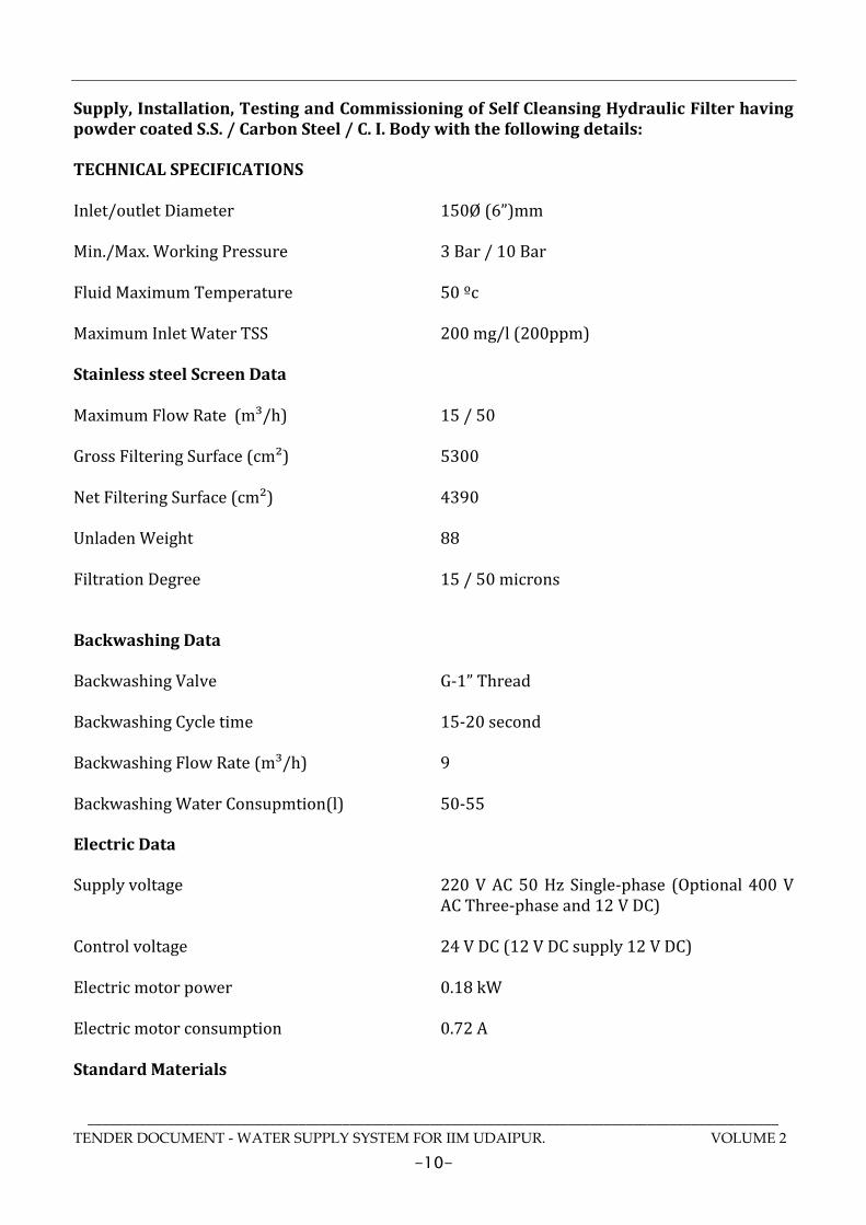
Supply, Installation, Testing and Commissioning of Self Cleansing Hydraulic Filter having powder coated S.S. / Carbon Steel / C. I. Body with the following details: TECHNICAL SPECIFICATIONS Inlet/outlet Diameter 150Ø (6”)mm Min./Max. Working Pressure 3 Bar / 10 Bar Fluid Maximum Temperature 50 ºc Maximum Inlet Water TSS 200 mg/l (200ppm) Stainless steel Screen Data Maximum Flow Rate (m³/h) 15 / 50 Gross Filtering Surface (cm²) 5300 Net Filtering Surface (cm²) 4390 Unladen Weight 88 Filtration Degree 15 / 50 microns Backwashing Data Backwashing Valve G-1” Thread Backwashing Cycle time 15-20 second Backwashing Flow Rate (m³/h) 9 Backwashing Water Consupmtion(l) 50-55 Electric Data Supply voltage 220 V AC 50 Hz Single-phase (Optional 400 V
AC Three-phase and 12 V DC) Control voltage 24 V DC (12 V DC supply 12 V DC) Electric motor power 0.18 kW Electric motor consumption 0.72 A Standard Materials

_______________________________________________________________________________________________
TENDER DOCUMENT - WATER SUPPLY SYSTEM FOR IIM UDAIPUR. VOLUME 2
-11-
Filter housing and lids S-235-JR carbon steel Finish treatment Kiln Polymerized epoxy-polyester powder
coating Suction scanner AISI-304 stainless steel Filtration screen AISI-316 stainless steel Suction nozzles PVC with AISI 316 stainless steel ring and
nylon brushes Backwashing vavles Polypropylene MODE OF MEASUREMENT
The measurement shall be for one set.
MODE OF PAYMENT
The contract rate shall be for one set.

_______________________________________________________________________________________________
TENDER DOCUMENT - WATER SUPPLY SYSTEM FOR IIM UDAIPUR. VOLUME 2
-12-
Item 3.0 : Electronic Flow Meters Providing & fixing on line turbine type flow meter with preamplifier & microprocessor based electronic flow meter mounted in plumbing plant room electrical control panel with the following features. Monitoring the total flow, Flow rate, high low arm batching and blending etc. Including electrical wiring from preamplifier to microprocessor based flow meter. Complete with all type of Plumbing & Electrical connections, accessories, wiring, conduits & supports complete with all respect. The signal from read out shall be 4-20 m.amps to be received on BAS. TECHNICAL SPECIFICATION: Principal Turbine flow meter Material: Body Stainless Steel / Carbon Steel Flange Stainless Steel / Carbon Steel Rotor Stainless Steel / ANC21 Bearing Support Stainless Steel Bearing Tungsten carbide, SS ball bearing General: Accuracy Linearity (+/- 0.5% over 10% to 100% flow range) Repeatability (+/- 0.02% to 0.05% on 95% confidence level) Temperature Rang -20°C to +150°C Pressure Drop 4 PSI Maximum Pressure 4000 PSI MODE OF MEASUREMENT
The measurement shall be for one no.
MODE OF PAYMENT
The contract rate shall be for one no. Item 4.0 : Pressure Release Valves

_______________________________________________________________________________________________
TENDER DOCUMENT - WATER SUPPLY SYSTEM FOR IIM UDAIPUR. VOLUME 2
-13-
Providing, installation, testing and commissioning of Pressure Release Valves of following sizes complete in all respect Construction The pressure reducing valve comprises: • Housing with pressure gauge connection G1/4"" • Spring bonnet with adjustment opening • Green adjustment knob • Adjustment spring • Pressure gauge not included (see accessories) Materials • Dezincification resistant brass housing • High-quality synthetic material spring bonnet • Spring steel adjustment spring • NBR seals Range of Application Medium Water Inlet pressure max. 16 bar Outlet pressure 1.5-6 bar adjustable Installation position Horizontal and vertical installation position possible In vertical installation position spring bonnet with adjustment knob facing upwards Operating temperature max. 40°C accord. to DIN EN 1567 max. 70°C (max. operating pressure 10 bar) Minimum pressure drop 1 bar Connection size 3/8", 1/2", 3/4" Method of Operation Spring loaded pressure reducing valves operate by means of a force equalising system. The force of a piston operates against the force of an adjustment spring. If the outlet pressure and therefore piston force fall because water is drawn, the greater force of the spring causes the valve to open. The outlet pressure then increases until the forces between the piston and the spring are equal again. The inlet pressure has no influence in either opening or closing of the valve. Because of this, inlet pressure fluctuation does not influence the outlet pressure, thus providing inlet pressure balancing. MODE OF MEASUREMENT
The measurement shall be for one no.
MODE OF PAYMENT
The contract rate shall be for one no. Item no. 5 Hydraulic Self cleaning Filter with UV Filter

_______________________________________________________________________________________________
TENDER DOCUMENT - WATER SUPPLY SYSTEM FOR IIM UDAIPUR. VOLUME 2
-14-
Supply, Installation, Testing and Commissioning of Self Cleansing Hydraulic Filter with electrical actuation and disinfection treatment by means of ultraviolet lamps having S.S.316 LBody with the following details GENERAL DATA Maximum flow (m3/h): 15; Inlet/Outlet diameter: 80 mm (3"); Maximum/minimum working pressure: 10 Bar / 3 Bar; Fluid maximum temperature: 40⁰ C; Filtration degrees: 25 microns; Maximum Inlet water TSS: up to 50 ppm ELECTRICAL DATA Rated operation voltage: 415 Volts AC 50 Hz three phase; Control voltage: 24V DC;