90-mm gun m3 mounted in combat vehicles · tm 9-374, 90-mm gun m3 mounted in combat vehicles, is...
TRANSCRIPT

UNCLASS1F1E
WAR DEPARTMENT TECHNICAL MANUAL
90-MM GUN M3MOUNTED IN
COMBAT VEHICLESREGRADED UNCLASSIFIED BY
DIR. 5200.1R
WAR DEPARTMENT 11 SEPTEMBER 1944
UNCLASSIFIED

WAR DEPARTMENT TECHNICAL MANUAL TM 9-374
90-MM GUN M3MOUNTED IN
COMBAT VEHICLES
WAR DEPARTMENT • 11 SEPTEMBER 1944
RESTRICTED DISSEMINATION OF RESTRICTED MATTER—The information contained in restricted documents and the essential char acteristics of restricted material may be given to any person known to be in the service of the United States and to persons of undoubted loyalty and discretion who are cooperating in Government work, but will not be com municated to the public or to the press except by authorized military public relations agencies. (See also paragraph 236, AR 380-5, 15 March 1944.)

WAR DEPARTMENT Washington 25, D. C., 11 September 1944
TM 9-374, 90-mm Gun M3 Mounted in Combat Vehicles, is pub lished for the information and guidance of all concerned.
[ A.G. 300.7 (13 Sep 44) "I O.O. 461/58719 Misc. J
BY ORDER OF THE SECRETARY OF WAR:
G. C. MARSHALL,Chief of Staff.
OFFICIAL:J. A. ULIO,
Major General,The Adjutant General.
DISTRIBUTION: Armies (10); Corps (10); SvC (10); Depts (10); D (2); IBn 9 (2); 1C 9 (3); C & H 17 & 18 (2); Tech Sv (2); Arm & Sv Boards (2); Posts, Camps & Stas (1); Gen & Sp Sv Sch (10); Ord Decentralized Sub-O (3); Ord Dist O (5); Ord Regional O (3); PE (Mark for Ord O) (5); H 8s R Points (5); Ord Dist Br O (3); Ord Estab (5).
IBn 9 T/O & E 9-65; 9-76.
1C 9 T/O & E 9-7; 9-9; 9-57; 9-67; 9-318; 9-377.
(For explanation of symbols, see FM 21-6.)

CONTENTS
PART ONE INTRODUCTIONParagraphs Pages
SECTION I. General .......................................... 1-2 1-4II. Description and data .................... 3- 6 4-12
III. Tools, parts, and accessories ....... 7- 8 13-15
PART TWO OPERATING INSTRUCTIONS SECTION IV. General .......................................... 9 16
V. Service upon receipt of materiel.... 10 12 16 17VI. Controls and instruments ......... 13-17 18-21
VII. Operation under usual conditions . 18-21 21-32VIII. Operation under unusual condi
tions .......................................... 22-26 33I.. Demolition to prevent enemy use . 27-29 34
PART THREE MAINTENANCE INSTRUCTIONSSECTION X. General .......................................... 30-31 35
XI. Lubrication .................................... 32-35 36-43XII. Preventive maintenance service.... 36-38 43-48
XIII. Malfunctions and corrections ....... 39-41 48-50XIV. Breech mechanism ........................ 42-52 50-6.2XV. Closing spring cylinder.................. 53 ' 62-64
XVI. Percussion mechanism .................. 54-59 64-71XVII. Gun recoil guard .......................... 60 71-72
XVIII. Firing mechanism ........................ 61 72-77XIX. Breech operating mechanism ...... 62 77XX. Firing switch box and firing trig
ger ............................................. 63-64 77-80XXI. Recoil cylinders ............................ 65 80-84
PART FOUR AUXILIARY EQUIPMENT SECTION XXII. General .......................................... 66 85
XXIII. Ammunition .................................. 67-75 85-96XXIV. Sighting and fire control equip
ment .......................................... 76-87 97-123
APPENDIX SECTION XXV. Shipment and storage................... 88-89 124-126
XXVI. References .................................... 90-92 127-129
INDEX .................................................................................... 130-132

MA
CH
INE
GU
N,
CA
L. .
50,
HB,
M2
9 o c u i n
O
£
o
RA
PO
76378
m
to
Fig
ure
I - 9
0-m
m
Gu
n
Mo
tor
Carr
iag
e
T7I
(M3
6) - T
hre
e-q
uart
er
Rig
ht
Fro
nt
Vie
w

TM 9-374 1-2
RESTRICTED
PART ONE - INTRODUCTION
Section I
GENERAL
1. SCOPE.*
a. This manual is published for the information of the using arms and services.
b. In addition to a description of the 90-mm Gun M3, Combina tion Gun Mounts T99, T99E1, and T99E2, and the Gun Mount T8 (M4), this manual contains technical information required for the identification, use, and care of the materiel.
c. In all cases where the nature of the repair, modification, or adjustment is beyond the scope or facilities of the unit, the responsible Ordnance service should be informed so that the trained personnel with suitable tools and equipment may be provided, or proper instruc tions issued.
2. RECORDS.
a. Artillery Gun Book.
(1) The Artillery Gun Book (O.O. Form 5825) is used for the purpose of keeping an accurate record of the materiel. It must always remain with the materiel regardless of where it may be sent. The book is divided as follows: record of assignment; battery commander's daily gun record; inspector's record of examination; forms to be filled in case of premature explosions. This book should be in the posses sion of organization at all times, and its completeness of records and its whereabouts are the responsibility of the battery commander. It must also contain date of issuance of the materiel, by whom used and the place where issued. If a new howitzer is installed on the carriage, all data recorded in the old book with reference to sights, mounts, etc., must be copied into new book before the old book is relinquished. If a gun book is lost, it should be replaced at once and all entries brought up to date. Additional copies may be obtained by requisition to Sup ply and Maintenance Department, Raritan Arsenal, Metuchen, New Jersey, on WD AGO Form No. 445. NOTE: Record of assignment data must be removed and destroyed prior to entering combat.
*To provide operating instructions with the materiel, this Technical Manual has been published in advance of complete technical review. Any errors or omis sions will be corrected by changes or, if extensive, by an early revision.
1

TM 9-3742
90-MM GUN M3 MOUNTED IN COMBAT VEHICLES
o
D
r
IQ
I
IV
IM
£ J>

TM 9-374 2
GENERAL
.*»
I
D)
o o-
-ae
I E
'•vID
3 O)

TM 9-374 2-3
90-MM GUN M3 MOUNTED IN COMBAT VEHICLES
(2) Complete instructions on how to make entries in the Artillery Gun Book are contained therein. It is absolutely essential that the gun book entries be kept complete and up to date. In order to facili tate proper maintenance of the cannon and its related materiel (that is, carriage, recoil mechanism, and associated fire control equipment), and to avoid unnecessary duplication of repairs and maintenance, the following additional entries are to be made in the gun book.
(a) A record of complete Modification Work Orders. This rec ord should show the date completed and bear the initials of the officer or mechanic responsible for completion of the modification.
(b) A record of seasonal changes of lubricants and recoil oil in sufficient detail to prevent duplication and afford proper identification by the inspector.
(3) The estimated accuracy life for cannon may be found in Changes No. 1 to Technical Manual 9-1860 for making the entry in the blank space immediately under inspector's record. The reference to Ordnance Field Service Bulletin 4-1 in instruction number 6 in the gun book should be corrected accordingly.
b. Field Report of Accidents. When an accident involving the use of ammunition occurs during training practice, the procedure pre scribed in Army Regulation 750-10 will be observed by the Ordnance officer under whose supervision the ammunition is maintained or issued. Where practicable, reports covering malfunctions of ammuni tion in combat will be made to the Chief of Ordnance, giving the type of malfunction, the type of ammunition, the lot number of the com plete rounds or separate loading components, and the condition under which fired.
c. Unsatisfactory Equipment Report. Suggestions for improve ment in design, maintenance, safety, and efficiency of operation prompted by chronic failure or malfunction of the weapon, spare parts, or equipment should be reported on AGO Form No. 468, Un satisfactory Equipment Report, with all pertinent information neces sary to initiate corrective action. The report should be forwarded to the Office, Chief of Ordnance, Field Service Division, Maintenance Branch, through command channels in accordance with instruction number 7 on the form. Such suggestions are encouraged in order that other organizations may benefit.
Section II
DESCRIPTION AND DATA
3. GENERAL.a. The 90-mm Gun M3 consists of the 90-mm Gun Ml so modi
fied as to adapt the gun for use in tanks and gun motor carriages. This gun is a flat trajectory weapon of the field gun type with an auto-

TM 9-374 3
DESCRIPTION AND DATA
e
O E
I
D>

TM 9-3743-4
90-MM GUN M3 MOUNTED IN COMBAT VEHICLES
RA PD 76379
Figure 4 — 90-mm Gun Motor Carriage T71 (M36) — Top View of Turret
matically operated vertical sliding drop block breechblock.
b. The Gun Mount T8 (M4) is designed to support and control the 90-mm Gun M3 in the turret of the Gun Motor Carriage T71 (M36). The Combination Gun Mount T99 is designed to support and control the 90-mm Gun M3 in the turret of the Tank T25E1. The Combination Gun Mounts T99E1 and T99E2 are designed to support and control the 90-mm Gun M3 in the turret of the Tank T26E1.
c. The mounts are located in the forward portion of the turret and are so constructed and attached as to permit the gun and mount to traverse as a unit with the turret. The turret can be operated either manually or hydraulically, as is designed to traverse to the left or right a full 360 degrees.
4. IDENTIFICATION INFORMATION.
a. The 90-mm Gun M3 is the 90-mm Gun Ml with the following modifications: the elimination of side rails for sliding support of the gun and carriage, and provision of a cylindrical surface on the tube for that purpose; and the addition of a handle for manual opening of the breech (fig. 3). The markings for gun are located on the top of the breech ring (fig. 5).

TM 9-374 5-6
DESCRIPTION AND DATA
PD 59Q66
Figure S — Gun Markings on Breech Ring
5. DIFFERENCE AMONG MODELS.
a. Difference Between Combination Gun Mounts T99 and T99E1. The Combination Gun Mount T99 has a SVa-inch armor basis for the gun shield and the T99E1 has a 4V2-inch armor basis for the gun shield.
b. Difference Between Combination Gun Mounts T99 and T99E1 and Gun Mount T8. The Gun Mount T8 has a 3-inch armor basis for the gun shield, and the coaxial machine gun and the peri scope linkage are omitted.
c. Difference Between the Combination Gun Mounts T99E1and T99E2. T99E1, after the first ten, has the following changes: an equilibrator has been added, the traveling lock, recoil guard, and elevating mechanism were redesigned thus changing designation from the T99E1 to the Combination Gun Mount T99E2.
6. DATA.
a. Data Pertaining to 90-mm Gun M3.(1) GENERAL.
Weight of gun .......................................................................... 2,2601bWeight of tube ........................................................................... 1,465 Ib

TM 9-374 6
90-MM GUN M3 MOUNTED IN COMBAT VEHICLES
o
e O.oo2o u
•o o
c OE
I
o>

TM 9-374 6
DESCRIPTION AND DATA
£<
I
o
c O.o"5
IS
I•o o
c OE E
IK
o>

ELE
VA
TIO
N
QU
AD
RA
NT
M9
GU
N
SH
IELD
TELE
SCO
PE
MO
UN
T T
90I O i
•"P CO
REA
R
CR
AD
LE)
SLEE
VE
LIN
ER
J
O O
I O m
RA
P
D
5907
1
Fig
ure
8 - C
ombi
natio
n G
un M
ount
799

TM 9-374 6
DESCRIPTION AND DATA
"S
Ico
3 O
eo.0
D
15Ou
1o-,
IO)
II

TM 9-374 6
90-MM GUN M3 MOUNTED IN COMBAT VEHICLES
Length of tube ........................................................................................
Length of tube (muzzle to rear face of breech ring) .......... 186.15 in.
Length of bore .............................................................................. SOcal
Length of rifling ..................................................................... 152.4in.
Type of breechblock .............................................. Sliding drop block
Weight of breechblock ............................................................................
Type of firing mechanism ................................ Percussion mechanism
Ammunition ........ For complete ammunition data see section XXIII.
( 2 ) PERFORMANCE.
* Muzzle velocity:
H.E. shell .................................................................. 2,700ftpersec
A.P.C. projectile ........................................................ 2,670ftpersec
A.P. shot .................................................................... 2,700ftpersec
* Range:
H.E. shell (at 45 deg, 37 min).......................................... 19,560yd
A.P.C. projectile (at 1 deg, 45 min). ................................. 3,500yd
A.P. shot (at 2 deg, 30 min).............. ................................. 3,500yd
b. Data Pertaining to Combination Gun Mounts T99, T99E1, and T99E2 and Gun Mount T8.
Gun Mount Combination Combination Combination T8 (M4I Gun Mount T99 Gun Mount T99EI Gun Mount T99E2
Maximum elevation ........ 30 deg 20 deg 20 deg 20 deg
Maximum depression ...... 10 deg 10 deg 10 deg 10 deg
Length of recoil(maximum) .................. 14 in. 14 in. 14 in.
Length of recoil (normal) 11^4 in. 12^4 in. 12^6 in.
Type of recoil mecha nism ................................ Hydrospring Hydrospring Hydrospring
Armor thickness, baseshield (approx) ............ 3 in. 3% in. 4 l/2 in.
Minimum time required for hydraulic traverse of 360 degrees ................ 17 sec 17 sec 17 sec 17 sec
*From FT 90-C-2 applicable to gun mounted in motor carriages.
12

TM 9-374 7-8
Section III
TOOLS, PARTS, AND ACCESSORIES
7. ORGANIZATIONAL SPARE PARTS.
a. A set of organizational spare parts is supplied to the using arm for field replacement of those parts most likely to become broken, worn, or otherwise unserviceable. The set will be kept complete by requisitioning new parts for those used. The parts comprising the set are listed below for information only; this list will not be used for requisitioning. The authority upon which requisitions are based is SNL D-39.
Spore Part Piece Mark
CHAIN ................................................................................ A7225000GASKET A168098 MECHANISM, percussion, assembly ..... ........................ A207706PIN ................................................................................PLUG ............................................................................PLUG ............................................................................SPRING ........................................................................SPRING ........................................................................SPRING
A25829A187175A245998A25833A25835A25836
8. ACCESSORIES.
a. Accessories include the tools and equipment required for such disassembling and assembling as the using arm is authorized to per form, and for the cleaning and preservation of the gun, mount, sight ing and fire control equipment, ammunition, etc. They also include chests, covers, tool rolls, and other items necessary to protect the materiel when it is not in use, or when traveling. Accessories should not be used for purposes other than as prescribed, and when not in use should be properly stored.
b. The accessories provided with each weapon are listed below. If it becomes necessary to replace a broken or missing accessory, this list should be checked with SNL D-39 which is the authority for requisitioning.
Accessory
BRUSH, bore, M19, w/staffs and wiper ring, complete
COVER, bore brush, MS 18
EYEBOLT, breechblock removing
FORM, War Dept., Arty. Gun Book (O.O. Form 5825) (blank)
Fig. No.
1
1
2
Slock No.
38-B-992-900
24-C-1059
41-E-3150
28-F-67990
*Use
Cleaning and oiling bore of gun.
To keep records.
*Where the accessory's use is not indicated, the nomenclature is self-explanatory or the accessory has general use.
13

TM 9-374 8
90-MM GUN M3 MOUNTED IN COMBAT VEHICLES
BRUSH, BORE, M29, W/STAFFS & WIPER RING, COMPLETE - 38-B-992-900
RINC-33-R-103
RA PD 57578
Figure 10 Tools and Accessories
WRENCH - 41-W-l596-50COVER - 24-C-1059
EYEBOLT -4I-E-3150
Figure 11 — Tools and Accessories
14
RA PD 57579

TM 9-374 8
TOOLS, PARTS, AND ACCESSORIES
Accessory Fig. No.
HEAD, rammer, cleaning andunloading 2
TOOL, breechblock removing 2
WRENCH, fuze, M7A1
Stock No.
41-H-1826-150
41-T-3076-815
41-W-1596-50
*Uie
Supports breech block during dis assembly.
For interchanging and tightening fuze. Also used to set fuze to "DELAY" or "SUPERQUICK."
"Where the accessory's use is not indicated, the nomenclature is self-explanatory or the accessory has general use.
15

TM 9-374 9-11
90-MM GUN M3 MOUNTED IN COMBAT VEHICLES
PART TWO - OPERATING INSTRUCTIONS
Section IV
GENERAL
9. SCOPE.
a. Part Two contains information for the guidance of the person nel responsible for the operation of this equipment. It contains in formation on the operation of the equipment with the description and location of the controls.
Section V
SERVICE UPON RECEIPT OF MATERIEL
10. GENERAL.a. Upon receipt of new or used materiel, it is the responsibility
of the officer in charge to ascertain whether it is complete and in sound operating condition. A record should be made of any missing parts and of any malfunctions, and any such conditions should be corrected as quickly as possible.
b. Attention should be given to small and minor parts, as these are the more likely to become lost and may seriously affect the proper functioning of the materiel.
c. The materiel should be cleaned and prepared for service in accordance with instructions given in section XII. The materiel should be lubricated in accordance with War Department Lubrication Order, section XI.
11. NEW EQUIPMENT.a. When a gun and mount are received by the using arm service,
the rust-preventive compound must be removed before the gun is inspected. The gun should be disassembled in detail and all parts cleaned with dry-cleaning solvent.
b. Clean bore with dry cloths to remove most of the rust-preven tive compound before using dry-cleaning solvent. The parts of the breech mechanism should 'be soaked in solvent while the bore and breech ring are being cleaned. When most of the rust preventive has been removed from the gun, soak a cloth in solvent and run it through the bore in order to remove the rest of the rust preventive. Clean the breech mechanism parts thoroughly and oil the tube and breech mechanism as prescribed in Part Three, section XI.
16

TM 9-374 11-12
SERVICE UPON RECEIPT OF MATERIEL
c. All lubricating fittings should be properly identified with red circles. Bearing, sliding surfaces, hinged joints, latches, and other movable parts should be cleaned and free from rust and other foreign matter and properly lubricated. Materiel should be kept lubricated according to Part Three, section XI.
d. Open and close breech manually. Action should be smooth. NOTE: The extfactors must be tripped to allow the closing spring to raise the breechblock to its fully closed position. CAUTION: Do not use hands to release the extractors.
e. Check the path of the recoil to make sure that it is free from all obstructions. Remove plugs on the recoil cylinder to determine if the recoil cylinders are full (par. 65).
f. Check the operation of the firing mechanism. The firing mech anism must be cocked each time it is desired to check operation (par. 61).
g. Tighten the extractor plunger plugs. Before loading, open breech and examine the bore of the gun to see that it is clear and free from foreign material. Be sure to return operating handle to its closed position.
h. Examine the gun and mount for general appearance. If the paint has deteriorated or become damaged, leaving exposed portions of bare metal, the materiel should be repainted.
i. Elevate and traverse weapon through complete range to check smoothness of operation (par. 38).
j. Check sighting equipment as given in section XXIV.
k. For bore sighting, refer to section XXIV.
1. Examine the Artillery Gun Book (O.O. Form 5825) to make sure that this record has been kept up to date and that all entries have been properly made. The gun book record will also serve to inform the inspector as to the number of rounds fired, maintenance and lubrication performed.
12. USED EQUIPMENT.a. The services required to insure proper operation of the mate
riel is identical with the information given in paragraph 11, except for the following additional points:
(1) During disassembly of the breech mechanism and the breech mechanism parts, examine all parts closely for signs of wear. If wear appears to be excessive, replace worn parts with new ones, or with parts that are declared usable by Ordnance maintenance personnel.
(2) Check Artillery Gun Book, section I, to make sure that all War Department Modification Work Orders are included.
17

TM 9-37413-16
90-MM GUN M3 MOUNTED IN COMBAT VEHICLES
Section VI
CONTROLS AND INSTRUMENTS
13. BREECH OPERATING CONTROLS.a. Breech Operating Handle (figs. 3 and 12). The purpose of
the breech operating handle is to open and close the breech. This is done by grasping the grip portion of the breech operating handle and pressing handle down.
b. Hand Cocking Lever Handle (fig. 12). The purpose of the hand cocking lever handle is to cock the percussion mechanism. This is done by rotating the handle.
14. ELEVATING CONTROLS.
a. Elevating Handwheel (fig. 21). The purpose of the elevating handwheel is to elevate and depress the gun. This is done by turning the elevating handwheel.
15. FIRING CONTROLS.
a. Manual Firing Pedal 90-mm Gun Motor Carriage T71 (M36) and Tanks T25E1 and T26E1 (fig. 22). The purpose of the manual firing pedal is to fire the 90-mm gun manually. This is done by pressing down on the firing pedal.
b. Firing Switches in Tanks T25E1 and T26E1 Only (fig. 11). The purpose of these switches is to fire the 90-mm gun solenoid and caliber .30 machine gun solenoid. This is done by pressing down on each button, respectively, on the front of switch box.
c. Firing Trigger or Finger Switch in 90-mm Gun Carriage T71 (M36) and Tanks T25E1 and T26E1 (figs. 20 and 21). The purpose of the firing trigger or finger switch is to operate the 90-mm gun electrically. This is done by depressing the trigger.
16. TRAVERSING CONTROLS.
a. Turret Lock (fig. 18). The purpose of the turret lock is to lock the turret in locked position when gun is in traveling position. This is done by pulling, and rotating handle of turret lock.
b. Manual Traverse Control Handle (fig. 10). The purpose of manual traverse control handle is to rotate the turret. This is done by rotating the handle after the turret lock has been disengaged.
c. Power Traverse Control Handle (fig. 13). The purpose of the power traverse control handle is to traverse the turret. This is done by turning the power traverse control handle either to the right
18

CONTROLS AND INSTRUMENTS
_l 00 I§ --o
TM 9-374 16
O^uj K
£ 2Z ?uj < < Ni-5i <
i u. 9-U O
<ca
I•a a
O
2
19

TELE
SCO
PE M
71C
TELE
SCOP
E SIG
HT;
HEAD
REST
ASS
EMBL
Y
ELE
VA
TIO
N
QU
AD
RA
NT
M9
(MA
NU
AL
TRAV
ERSE
IC
ON
1RO
L H
AN
DLE
o to O Z
-I
m O Z o•A
ZIM
UT
H
IND
ICA
TOR
M19
CA
L .3
0 M
AC
HIN
E G
UN
FIR
ING
SW
ITC
H
/ 90
MM
GU
N
FIR
ING
SW
ITC
H
r>\iP
OW
ER
TR
AVER
SE
(CO
NTR
OL
HA
ND
LE
w
RA
P
D
5908
0
Fig
ure
13
— T
urre
t C
on
tro
ls

TM 9-374 16-18
OPERATION UNDER USUAL CONDITIONS
or to the left, depending upon the direction of traverse after the turret lock has been disengaged.
d. Commander's Traverse Control Handle on Tanks T25E1 and T26E1 Only (fig. 15). The purpose of the commander's traverse control handle is to traverse the turret. This is done by either push ing the handle forward or pulling it backward after the turret lock has been disengaged.
17. INSTRUMENTS.
a. The only instruments required for the gun and mount are the fire control instruments listed in section XXIV.
Section VII
OPERATION UNDER USUAL CONDITIONS
18. PLACING 90-MM GUN IN FIRING POSITION,
a. Gun Covers. Remove muzzle and breech covers.
b. To Disengage Traveling Lock in Tanks T25E1 and T26E1 Only. Remove traveling lock from gun by unscrewing traveling lock
yMi l3i |4i l5i |6i
RA PD 59072
Figure 14 — Muzzle Cover — Installed
21

M
M
•2
O c z c m O O
TRA
VE
LIN
G
PO
SIT
ION
LATC
HE
D
PO
SIT
ION
Figu
re 1
5 - 9
0-m
m G
un T
rave
ling
lock

TM 9-374 18-19
OPERATION UNDER USUAL CONDITIONS
RA PD 63035
Figure ISA — 90-mm Gun Motor Carriage T7I (M36) — Traveling Lock
handle, and swing the top half of the lock over the gun tube. Screw traveling lock handle in place by means of traveling lock latch.
c. To Disengage Traveling Lock for the 90-mm Gun Motor Carriage T71 (M36). Remove traveling lock from gun by pulling out locking pin which locks the gun to the rear deck (fig. 15 a).
d. To Disengage Cradle Traveling Lock. Remove pin from lock.
e. To Disengage Turret Lock. Disengage the turret lock by turning the handle, pulling it out, and rotating one-quarter turn clock wise.
19. TO LOAD.
a. Refer to paragraph 37 for points of inspection and lubrication before and during firing.
b. To Open Breech. To open the breech manually, unlatch the operating handle from the operating handle latch catch. Push the breechblock operating handle down until the extractors lock the breech in open position or until a distinct click can be heard, and then lift the breechblock operating handle up and latch it on the operating handle latch catch. Keep hands out of gun when breech is open. Return breechblock operating handle to the closed position immedi ately after opening breech in order to avoid injury to personnel and mechanism.
23

TM 9-374 19
90-MM GUN M3 MOUNTED IN COMBAT VEHICLES
BREECH OPERATING MECHANISM EXTRACTOR
BREECHOPERATING
HANDLE
RA PD S9234
Figure 16 — Breechblock in Open Position
c. To Insert Ammunition. Place a round in the breech with the nose protruding in the bore. The loader's.hand should be moving upward as he shoves the projectile home.
d. Closing Breech.(1) Normally the action of the breech is closed by inserting the
shell into the breech recess with sufficient force to trip the extractors and allow the breech to close, due to the tension of the spring in the closing spring cylinder.
(2) After the firing period, the breech may be closed without inserting a round in the breech recess, by first unlatching the operat ing handle and pressing down. Bear sufficient weight on the handle to overcome the tension of the closing spring, and release the extractors from their locking position by pressing them forward with the base of an empty cartridge case or a block of wood. The breechblock is then free to be eased into its closed position by means of the operating handle which should be finally latched in place. CAUTION: Do not use hands to release extractors.
(3) Under ordinary conditions it will be necessary to open the breech only at the start of firing operation. A cam attached to the crank arm within the breech mechanism is operated by the recoil
24

TM 9-374 19-20
OPERATION UNDER USUAL CONDITIONS
GUN RECOIL GUARD
BREECH BREECHBLOCK RING
HAND COCKING LEVER
RA PD 59235
Figure 17 — Breechblock in Closed Position
of the gun after firing, and serves to open the breech and extract the empty cartridge case during the recoil and return of gun to battery.
20. TO FIRE.
a. Prior to firing, the gun must be placed in proper position of elevation and traverse.
(1) To ELEVATE. Rotate the elevating handwheel clockwise. To depress the gun, rotate elevating handwheel counterclockwise.
(2) To TRAVERSE TURRET.(a) Power Operation. Before traversing turret by means of the
hydraulic traversing mechanism, make sure personnel are clear of rotating parts. Move gearshift lever in front of gunner and under gear mechanism to the power position (pull lever up toward the top of turret). It may be necessary to turn slightly the manual drive handle on top of gear mechanism to engage gears. Turn traversing motor switch to the "ON" position to start electric drive motor (fig. 21). Disengage turret lock (fig. 18). It is important to have turret lock completely disengaged before traversing turret and to
25

TM 9-374 20
90-MM GUN M3 MOUNTED IN COMBAT VEHICLES
Figure 18 — Turret Lock in Disengaged Position
lock turret in position if need for traversing is completed (par. 16). (b) Manual Operation. If electric power fails or if hydraulic
traverse system will not operate, due to some other cause, the turret can be rotated by the manual traverse control handle located on top of the gear mechanism to the right of the gunner's seat. Disengage turret lock. Move gearshift lever under gear mechanism to the manual position (turn lever down toward the floor of turret). It may be necessary to turn slightly the manual traverse control handle on top of the gear mechanism to engage gears. The manually operated gears are then engaged with the turret ring gear and pinion. Grip the manual traverse control handle and its associate lever on top of gear mechanism in front of the gunner to release brake in gear box (par. 15 a and 16 b).
b. During Firing. Normally, the weapon is fired electrically.(1) To FIRE ELECTRICALLY ON TANKS T25E1 AND T26E1 ONLY.(a) There are two foot-operated firing switches mounted in a
switch box on the turret floor, convenient to the gunner. The right one operates the 90-mm gun solenoid; and the left one, the caliber .30 machine gun solenoid.
26

TM 9-374 20-21
OPERATION UNDER USUAL CONDITIONSTELESCOPIC HEADREST COMMANDER'S TRAVERSE CONTROL HANDLE
MANUAL TRAVERSE CONTROL HANDLE RA PD 59078
Figure 19 — Installation of Traverse Controls
(b) To fire the 90-mm gun electrically on 90-mm gun motor carriage and in Tanks T25E1 and T26E1, depress firing switch or finger switch on the power traverse control handle.
(2) To FIRE MANUALLY. If the solenoid does not function, the 90-mm gun may be fired manually by depressing the manual firing pedal located to the left and front of the gunner's seat on the turret floor.
c. After Firing. Push safety lever down to its safe position. This locks the firing shaft in position so that the gun can not be fired.
d. Gun Fails To Fire. If the gun fails to fire after check in steps (1) and (2), above, the position of the safety lever should be checked. The failure to fire may be due to the gun staying out of battery, failure of the firing mechanism, failure of the breech to close, or defective ammunition. If the gun is in battery, recock by means of the cocking lever on the right side of the breech, and attempt to fire; if the gun still fails to fire after three attempts, wait 30 seconds before opening the breech; then remove round, reload, and attempt to fire again.
21. PLACING THE GUN IN TRAVELING POSITION.a. Refer to paragraph 37 for points of inspection, cleaning, and
lubrication to be observed after firing.b. To Engage Traveling Lock. Place gun in traveling position
by taking traveling lock out of traveling lock latch (fig. 15). Un screw the halves of the traveling lock by means of the traveling lock handle. Place the halves of the traveling lock around gun tube, and screw tight with traveling lock handle (fig. 15).
27

TM 9-37421
90-MM GUN M3 MOUNTED IN COMBAT VEHICLES
o•s4)5
Ol
28

TM 9-374 21
OPERATION UNDER USUAL CONDITIONS
D
o35
Xo co
o u
01

TELE
SCO
PE
T93E
3
TRAV
ELIN
G
LOC
K
INST
RUM
ENT
LIG
HT—
M30
ELEV
ATIO
NQ
UAD
RAN
TM
9
S O C
2-0 w
n
O m O
m
RA
PD
7637
7
Fig
ure
22 —
90-
mm
Gun
Mot
or C
arri
age
771
fM36
>-
Vie
w o
f R
ight
Si
de o
f T
urre
t

TM 9-374 21
OPERATION UNDER USUAL CONDITIONS
9 ' MM GUN HRING V.'/ITCH
RA PD 4O026
Figure 23 — Firing Switches and Manual Firing Pedal
c. To Engage Traveling Lock for the 90-mm Gun Motor Car- riage T71 (M36). Place gun in traveling position by placing link around gun tube and inserting locking pin (fig. 15 a).
d. To Engage Cradle Traveling Lock. Install pin in cradle traveling lock.
e. To Engage Turret Lock. Lock turret in traveling position by pulling, turning, and rotating the handle of turret lock a quarter turn counterclockwise (fig. 12).
f. Gun Covers. Install muzzle and breech covers (figs. 14 and 24).
31

TM 9-374 21
90-MM GUN M3 MOUNTED IN COMBAT VEHICLES
IsHI
I
c3oEE
§
4)£ coI
3 O>
32

TM 9-374 22-26
Section VIII
OPERATION UNDER UNUSUAL CONDITIONS
22. GENERAL.
a. When operating the gun under unusual conditions, such as tropical or arctic climates, severe dust or sand conditions, and loca tions near salt water, the precautions below should be followed.
23. EXTREME COLD.
a. Do not clean the gun bore with solutions that may freeze. Bore should be inspected frequently for frosting or congealed lubricants. Care must be taken to make certain that parts are alined properly and normal clearances exist, not only in bearing but also in mecha nisms employing packings around rotating or reciprocating shafts and rods. Care must be taken not to overlook cleaning small items that may appear insignificant.
24. TROPICAL CLIMATES.
a. In hot and for tropical climates where humidity is high, or where salt air is present, inspect and clean frequently as required, and also at fixed intervals. Clean and lubricate as soon as possible after firing or if there is any reason to expect corrosion to start. .
25. EXTREME DUST AND SAND CONDITIONS.
a. When the gun is active in dusty areas, remove lubricants from exposed sliding parts and elevating racks and pinion, as they will pick up sand or dust, forming an abrasive which will cause rapid wear. Lubricate parts after action (sec. XI).
h. Clean, inspect, and lubricate the materiel more frequently when operating in sandy areas.
26. NEAR SALT WATER AREAS.
a. When the materiel is inactive, the unpainted parts should be covered with a film of light rust-preventive compound. Repaint painted surfaces where paint has been removed. The bore of the tube and the breech mechanism should be kept heavily oiled and should be inspected frequently for rust. In the event that the pre scribed lubricant offers insufficient protection against rusting, use medium preservative lubricating oil in the bore and metal surface of the breech mechanism from which it can be readily removed.
33

TM 9-374 27-29
90-MM GUN M3 MOUNTED IN COMBAT VEHICLES
Section IX
DEMOLITION TO PREVENT ENEMY USE
27. GENERAL.a. The destruction of the materiel, subject to capture or abandon
ment in combat zone, will be undertaken by the using arms only when, in the judgment of the military commander concerned, such action is deemed necessary and as a final resort to keep the materiel from reaching enemy hands.
b. Adequate destruction of artillery materiel means damaging it in such a way that the enemy cannot restore it to usable condition in the combat zone either by repair or by cannibalization. Adequate destruction requires that:
(1) Enough parts essential to the operation of the materiel must be damaged.
(2) Parts must be damaged beyond repair in the combat zone.(3) The same parts must be destroyed on all materiel, so that the
enemy cannot make up one operating unit by assembling parts from several partly destroyed units.
c. The tube and breech are the most vital parts of any piece of artillery. These are the first things to damage. After the tube and breech, in importance come the recoil mechanism, sighting and fire control equipment, mount, vehicle gun book, and firing tables.
28. ADEQUATE AND UNIFORM DESTRUCTION OF MA TERIEL.
a. To accomplish adequate and uniform destruction of materiel, it is essential that the following procedures should be performed:
(1) All echelons prepare plans for the destruction of materiel in the event of imminent capture. Such plans must be flexible as to the available time, equipment, and personnel.
(2) All echelons be trained to effect the desired destruction of materiel issued to them.
29. METHOD OF DESTRUCTION IN ORDER OF EFFEC TIVENESS.
a. Insert four Unfuzed Incendiary Grenades M14 end to end mid way in the tube at 0 degrees elevation. Ignite these four grenades, with a fifth equipped with a 15-second safety fuze. Ela'psed time: 2 to 3 minutes.
b. The metal from the grenades will fuze with the tube and fill the grooves.
34

TAA 9-374 30-31
PART THREE - MAINTENANCE INSTRUCTIONS
Section X
GENERAL30. SCOPE.
a. Part Three contains information for the guidance of the per sonnel of the using organizations responsible for the maintenance (first and second echelon) of this equipment. In contains information needed for the performances of the scheduled lubrication and preven tive maintenance services, as well as description of the major systems and units and their functions in relation to other components of the equipment.
31. CLEANING, PRESERVING, AND LUBRICATING MATERIALS.
a. .The following cleaning, preserving, and lubricating materials are required for use with this materiel. See SNL K-l and TM 9-850 for detailed information. BURLAP, jute, 8 oz., 40 in. wideBRUSH, paint, metal-bound, flat (medium grade) No. 1, 3 in. CHALK, blue/white, railroad, 1 x 4 in. CLOTH, abrasive, aluminum-oxide, 5/0-180 (fine) CLOTH, abrasive, aluminum-oxide, 3/0-120 (medium) CLOTH, crocus CLOTH, wiping, cotton, mixed COMPOUND, rust-preventive, light ENAMEL, synthetic, olive-drab GREASE, O.D., No. 0/00 NEEDLES, sacking, steel, 4Vz in. OIL, engine, SAE 10/30 OIL, lubricating, preservative, special PAPER, lens, tissue (100 sheets per book) PRIMER, synthetic, rust-inhibitive SOLVENT, dry-cleaning SPONGE, cellulose, coarse pore, type A THINNER, enamel, synthetic TWINE, jute WASTE, cotton, white
35

TM 9-374 32-33
90-MM GUN M3 MOUNTED IN COMBAT VEHICLES
Section XI
LUBRICATION
32. LUBRICATION ORDER (GUIDE).
a. War Department Lubrication Orders No. 148 and No. 156 (figs. 25 and 26) (formerly referred to as War Department Lubrica tion Guides No. 148 and No. 156) prescribe first and second echelon lubrication maintenance.
b. The lubrication fittings indicated on the orders are illustrated in figure 27, showing their location on the materiel. The fittings shown in the figures may be identified on the order by the key num bers around the border.
c. A Lubrication Order (formerly referred to as War Department Lubrication Guide) is placed on, or issued with, each item of materiel and is to be carried with it at all times. In the event the materiel is received without an order, a replacement should be immediately requisitioned from the Commanding Officer, Fort Wayne Ordnance Depot, Detroit 32, Michigan.
33. GENERAL LUBRICATION INSTRUCTIONS.a. Lubricants. These are prescribed in the "Key" on the order
in accordance with three temperature ranges, "above -j-32° F," "from +32° F to 0° F," and "below 0° F." The time to change grades of lubricants is determined by maintaining a close check on the opera tion of the materiel during the approach to prolonged periods when temperatures will be consistently in a higher or lower range. Because of the time element involved in preparing for operation at lower prevailing temperatures, a change to lubricants prescribed for the next lower range will be undertaken the moment operation becomes sluggish. Ordinarily, it will be necessary to change lubricants only when expected air temperatures will be consistently in the next higher or lower range.
b. Service Intervals. These are specified for normal operating conditions and continuous use of the materiel with frequent firing. Reduce these intervals under extreme conditions such as excessively high or low temperature, prolonged periods of traveling or firing, con tinued operation in sand or dust, immersion in water, or exposure to moisture. Any one of these conditions may quickly destroy the pro tective qualities of the lubricant, and require servicing in order to prevent malfunctioning or damage to the materiel.
c. Lubrication Equipment.(1) Each piece of materiel is supplied with equipment for lubri
cating the materiel. Be sure to clean this equipment both before36

TM 9-374 33
LUBRICATION
and after use. Operate lubricating guns carefully and in such manner as to insure a proper distribution of the lubricant. If lubrication fitting valves stick and prevent the entrance of lubricant, remove the fitting and determine the cause. Replace broken or damaged lubri cators. If lubricator cannot be replaced immediately, cover hole with tape as a temporary expedient to prevent the entrance of dirt. If oil lines become clogged, disassemble the line and remove the obstruction.
(2) Lubrication fittings, grease cups, oilers, oilholes, and plugs are circled in red for ready identification.
(3) Wipe lubricators and surrounding surfaces clean before ap plying lubricant. Where relief valves are provided, apply new lubri cant until the old lubricant is forced from the vent. Exceptions are specified in notes or on the Lubrication Order. Metal surfaces on which a film of lubricant must be maintained by manual application will always be wiped clean before the film is renewed.
d. Cleaning.
(1) Unless otherwise specified, use dry-cleaning solvent or Diesel fuel oil to clean or wash all metal parts, whenever partial or total dis assembly is undertaken, or when renewing the protective lubricant film on exposed metal surfaces. Flushing of gear cases and bearing housings will not be undertaken unless inclosed mechanism is first disassembled in order to insure complete removal of the solvent prior to application of lubricants. Use of gasoline for cleaning purposes is prohibited. Dry all parts thoroughly before lubricating.
(2) Care must be taken when cleaning oil and grease compart ments to insure the complete removal of all residue or sediment. Dirt or other foreign matter should not be allowed to drop into any of the lubricating compartments.
(3) Swab the gun bore immediately after firing, while the tube is still hot, and daily thereafter on the following three days, with a solution of one-half pound of soda ash to each gallon of warm water. Rinse thoroughly with clean water and dry thoroughly before oiling.
e. The following paragraphs present the notes on the Lubrication Order which pertain to lubrication and service of individual units and assemblies, together with supplementary instructions on the method of performing the prescribed lubrication services:
(1) BREECH AND FIRING MECHANISM. Daily and after firing, clean with dry-cleaning solvent and then oil all moving parts and unpainted surfaces with engine oil SAE 30 above +32° F, SAE 10 from +32° F to 0° F, and special preservative lubricating oil below 0° F. To clean firing mechanism, remove and operate pin in dry- cleaning solvent.
37

u 00
«D
TA
NK
, M
ED
IUM
. T2
5E1
Cle
an f
ittin
gs b
efor
e lu
bric
atin
g. L
ubric
ate
afte
rw
ashi
ng.
Redu
ce i
nter
vals
und
er s
ever
e op
erat
ing
con
tions
.Lu
bric
ate
dotte
d ar
row
s on
bot
h si
des.
To c
lean
par
ts u
se
SOLV
ENT,
dry
-cle
anin
g,
o
OIL
. fu
el,
Dies
el.
Dry
bef
ore
lubr
icat
ing.
Sw
ab
gun
bore
with
a s
olut
ion
of l
/j po
und
of S
OD
A,
ash,
to
each
gal
lon
of w
arm
wat
er,
or w
ith a
thic
k su
ds o
f iss
ue s
oap
and
war
m w
ater
. Ri
nse
with
cl
ear
wat
er a
nd
dry
thor
ough
ly
befo
re
oilin
g.
Cle
an
mac
hine
gu
n bo
re
with
C
LEA
NER
, rif
le
bore
. D
ry t
horo
ughl
y be
fore
oili
ng.
Req
uisi
tion
repl
acem
ent
Gui
de
from
th
e C
omm
andi
ng O
ffic
er,
Fo
rt W
ayne
O
rdna
nce
Dep
ot. D
etro
it *
2, M
ichi
gan.
• if
k—
r-
'*•
***•
"•
Sld
* *o
r Im
bric
atio
n *f
NU
TC
.——
D
RIV
ER
S C
OM
PA
RTM
EN
T a»
tf T
UR
RE
T••
<•*
* •*
' P
OW
ER
UN
IT
OG
E
leva
ting
Gea
r Ca
se W
dii.
ti.m
bfy
, it
. O
rdni
nc*
Ptn
onnt
l N
ot*
)
OH
H
ydra
ulic
Oil
Tank
Fill
Hyd
raul
ic O
il Ta
nk L
et-el
Ch<e
k I..
.!. t
*.P
% M
lO
G
Firin
g C
able
Con
duit
CG
Tr
ack
Sup
port
Rol
ler
Hub
sC
G
Shoc
k A
bsor
ber
Mou
ntin
gs
Elev
atin
g W
orm
Hou
sing
O
G
M(4
) C
radl
e Li
ner
OG
M
(I)
Cra
dle
Trun
nion
Bea
rings
OG
M
xSh
ock
Abs
orbe
r M
ount
ings
C
G
Va v
Com
pens
atin
g W
heel
Hub
C
G
>/j.
Com
pens
atin
g A
rm
CG
Va
Hou
sing
C
ompe
nsat
ing
Arm
Lin
k C
G• V
i C
G
Tors
ion
Bar A
ncho
r Se
ats
\ Va
CG
T
rack
Vhe
ei H
ubs
Lubr
ieal
* 6
pU
»i
Sup
port
Arm
Hou
sing
s C
G^
U
bri
c..
. 5
pL
c«
§ S O z
w
O
8?w
o
O m

TM 9-37433
LUBRICATION
S S S § S Sa a > a o
lubr/cafion Order
39

,GU
IDE
OR
DN
AN
CE
DE
PA
RT
ME
NT
CA
RR
IAG
E, M
OT
OR
, G
UN
, 90
-mm
, T
71 (
M36
)Fo
r de
taile
d in
ttrue
),
relt
r to
TM
9-7
5S.
Cle
an f
illin
gs
befo
re
was
hing
.
Red
uce
inte
rval
s un
c tio
nj.
Lubr
icat
e d
ott
ed
arr
o
ubric
atin
g. L
ubric
ate
after
er s
ever
e op
erat
ing
cond
i-
w p
oint
s on
bot
h si
des.
Requis
ition
rep
lace
me
nt
Guid
e
from
th
e C
om
ma
nd
ing
Off
ice
r. F
ort
Wayn
e
Ord
na
nce
Depot, D
etr
oit 3
2, M
ichig
an.
I1U
IL
„,
ENG
INE
CO
MPA
RTM
ENT.
FI
N
AL
DR
IVE
and
FIG
HTI
NG
CO
M.
MR
TME
NT
pain
t*
Cle
an
part
s w
ith
SO
LVE
NT,
dr
y-cl
eani
ng
or
OIL
, fu
el.
Die
sel.
Dry
be
fore
lu
bric
atin
g.
Was
h gu
n bo
re w
ith a
sol
utio
n of
I/,
po
und
of S
OD
A,
ash,
to
eac
h ga
llon
of w
arm
wat
er o
r w
ith a
thi
ck
suds
of
issu
e so
ap
and
war
m
wat
er.
Rin
se
with
Cle
an
mad
ime
gun
bore
s w
ith
CLE
AN
ER
, rif
le
bore
.
Ele
vatin
g W
orm
Hou
sing
O
G
M -
(4)
Cra
dle
Line
r O
G
(1)
Cra
dle
Trun
nion
Be
arin
g O
G
• M
O
G E
leva
ting
Gea
r Ca
se (
2)(F
or d
:»i»
n.b
ly.
S*.
O
rdni
nc*
P.r
lonn
.l N
ot.
)
' W
O
H
Hyd
raul
ic T
rave
rse
Oil
Res
ervo
ir Fi
llC
heck
l.v«
l. U
ip V
] fu
ll
• M
OG
Firi
ng C
able
Con
duit
CG
Tr
ack
Sup
port
Rolle
rs
? o z u> O Z o
O a> O m
ui
w
<n cBo
gie
Whe
els
CG
"A
--
----
LEFT
SID
E O
F C
ARR
IAG
E AN
D T
URRE
T'•V
4 C
G
Sus
pens
ion
Sys
tem
Id
ler

o- o S' 8-
Daily
and
after
firm
, cl
etn
and
Oj|
Rec
oil
Cha
mbe
r Fi
lls
RS
D
M
OG
Fi
ring
Cab
le C
ondu
it (3
)
W
OG
Br
eech
Clo
sing
Cha
in
Bree
ch
Ope
ratin
g O
E
D M
echa
nism
Bree
ch M
echa
nism
O
E
DD
aily
and
after
firin
g.
D O
E
Firin
g M
echa
nism
Dai
ly a
nd a
lter
fir
ing
.d
em
an
d o
il
GU
N.
90-m
m.
M3
MO
UN
T. G
UN
, 90
-mm
, T-
8
OIL
CA
N P
OIN
TS
—W
ee
kly,
lub
rl
Firi
ng L
ev.r
Lin
t, et
c..
with
OE
.
LUB
RIC
ATE
D
BY
OR
DN
AN
CE
P
ER
SO
NN
EL
— E
Uv.
ting
S
B
reec
h O
per
atin
g S
haft
B8a
fing
(. (R
gfe
r to
TM
.)
Cop
y of
rn
ii G
ur'd
lu
bric
atio
n in
ttroc
l
By O
rder
of
the
Sec
reta
ry o
f W
ar:
G.
C.
Mar
shal
l. C
hie
f of
Sta
ff.
•fl
1 an
[NOT
T0 BE
REPR
ODUC
ED
c IP 30 O
RA
PD
59
238
53? u

TM 9-374 33
90-MM GUN M3 MOUNTED IN COMBAT VEHICLES
LUBRICATION FITTINGS
HANDWHEEL CROSS SHAFT
ELEVATING MECHANISM/ GEAR BOXJ
CRADLE LINER; LUBRICATION FITTING}
ELEVATING SHAFT) LUBRICATION FITTINGS
CRADLE TRAVELING LOCK
RECOIL CYLINDER FILLING PLUG
PERISCOPE LINKAGE
LUBRICATION FITTING
LUBRICATION FITTING
RA PD 63034
Figure 27 — Location of Lubrication Fittings
42

TM 9-374 33-36
PREVENTIVE MAINTENANCE SERVICE
(2) OILCAN POINTS. Weekly, lubricate handwheel handles, firing button, firing lever link, etc. with engine oil SAE 30 above +32° F, SAE 10 from +32° F to 0° F, and special preservative lubricating oil below 0° F.
34. POINTS TO BE SERVICED AND/OR LUBRICATED BY ORDNANCE MAINTENANCE PERSONNEL.
a. Elevating gear case and breech operating shaft bearings.
35. REPORTS AND RECORDS.a. Report unsatisfactory performance of materiel to the Ordnance
officer responsible for maintenance.b. Record of seasonal changes of lubricants and recoil oil will be
kept in the Artillery Gun Book.
Section XII
PREVENTIVE MAINTENANCE SERVICE
36. GENERAL.a. Scope. Preventive maintenance services prescribed by Army
Regulations are a function of using organization echelons of mainte nance. This section contains preventive maintenance service allo cated to crew and scheduled preventive maintenance service allocated to (second echelon) organizational maintenance.
b. It is of vital importance to keep all parts of the materiel in proper condition for immediate service. The proper use of tools and accessories, and lubricating, cleaning, and preserving materials is to keep the materiel in proper operating condition.
c. Proper lubrication, with lubricants and intervals prescribed in section XI, is essential to the care and preservation of gun and mount. Examination should be made periodically to insure that lubricants reach the parts for which they are intended.
d. All protective covers for the gun and mount should be installed when in traveling or when gun is not in service. If the materiel is not to be used for a considerable length of time, all exposed, bright, unpainted surfaces should be cleaned with dry-cleaning solvent, thor oughly dried, and protected with a coat of rust-preventive compound.
e. Should enemy shell burst near the weapon or after the gun has been under fire, it must be determined that the weapon is not damaged to a dangerous degree before further use of the gun. Dam age of a serious nature should be reported to the Ordnance officer.
43

TM 9-374 36-37
90-MM GUN M3 MOUNTED IN COMBAT VEHICLES
f. In disassembling and assembling, thoroughly clean dirt and grit from parts that are going to be removed and installed. Clean parts thoroughly before oiling and assembling. In assembling or disassem bling, do not use a steel hammer directly on any part. If copper or lead hammer is not available, use a block of wood as a buffer.
g. Water from a high-pressure hose must never be played into any part of the gun mount. Washing should be done with sponge. Carefully dry parts which have been wet during the washing opera tion, then oil them in the manner prescribed in section XI.
h. All organizational spare parts and accessories should be kept in an orderly manner so that they can be quickly located when re quired. Organizational spare parts and accessories for the gun and mount should be maintained as complete as possible at all times. They should be checked with the "Organizational Spare Parts and Accessories" of SNL D-39, and all items which are used for replace ment, or which are missing, should be replaced.
i. When the gun and mount are used in hot or cold climates or under extreme conditions of sand, dust, and salt water areas, refer to section VIII.
37. PREVENTIVE MAINTENANCE, a. Before Firing.(1) LUBRICATION. The following points should be thoroughly
lubricated as prescribed in section XI: Cradle trunnion bearings Elevating gear case Firing cable conduit Cradle linerBreech operating mechanism Firing mechanism Breech mechanism
(2) RECOIL CYLINDERS. Examine the recoil cylinders for leak age of oil. Check to determine whether or not the gun returns to battery. Check for the proper amount of oil, paragraph 65.
(3) GUN BORE. Check bore and chamber for dirt and obstruc tions. Clean out the bore with brush if necessary.
(4) BREECH MECHANISM. Examine breech mechanism and breech recess for function, corrosion, and rust. Clean and lubricate (par. 33).
(5) BREECH OPERATING MECHANISM. Examine for function and condition (par. 62).
(6) ELEVATING MECHANISM. Examine for function; clean and lubricate (par. 38).
44
TM 9-374 37
PREVENTIVE MAINTENANCE SERVICE
(7) TRAVERSING MECHANISM. Examine for function and lubri cation (par. 38).
(8) FIRING MECHANISM. Examine for function and adjustment (pars. 38 and 61). Clean and lubricate (figs. 25 and 26).
(9) CRADLE. Examine for condition (par. 38). Clean and lubri cate (figs. 25 and 26).
(10) ACCESSORIES. Make sure that all accessories are on hand and in good condition.
(11) AMMUNITION. Check for the proper amount and type of ammunition and that the rounds are clean and dry.
b. During Firing.
(1) GUN BORE. Wash and wipe dry. Examine for erosion, scratches, and markings (par. 38).
(2) BREECH MECHANISM. Examine for condition and lubrica tion. For correction of malfunction, refer to paragraph 40.
(3) BREECH OPERATING MECHANISM. For correction of malfunc tion, refer to paragraph 41.
(4) EXTRACTORS. For correction of malfunction, refer to para graph 40.
(5) FIRING MECHANISM. For correction of malfunction, refer to paragraphs 40 and 41.
(6) RECOIL CYLINDERS. For correction of malfunction, refer to paragraph 41.
c. After Firing.
(1) GUN BORE. Examine for condition, erosion, and lubrication (par, 38). Clean and lubricate (figs. 25 and 26).
(2) BREECH OPERATING MECHANISM. Examine for operation, condition, and lubrication (par. 38). Clean and lubricate (figs. 25 and 26).
(3) BREECH MECHANISM. Examine for operation and lubrication (par. 38). Clean and lubricate to insure proper functioning.
d. Daily Service.
(1) GUN BORE. Examine for condition, erosion, and lubrication (par. 38). Clean and lubricate (par. 33).
(2) RECOIL CYLINDERS. Examine recoil cylinders for leakage of oil. Check for the proper amount of oil.
(3) BREECH OPERATING MECHANISM. Examine for condition and lubrication (figs. 25 and 27).
(4) BREECH MECHANISM. Examine for operation and lubrication (par. 38). Clean and lubricate for proper functioning.
45

TM 9-374 37-38
90-MM GUN M3 MOUNTED IN COMBAT VEHICLES
(5) FIRING MECHANISM. Examine for functioning and adjust ment (par. 38). Clean and lubricate (figs. 25 and 26).
e. Weekly Service.(1) CRADLE LINER. Should be lubricated (figs. 25 and 26). f. 30-day Service.(1) CRADLE TRUNNION BEARINGS. Should be lubricated (fig.
27).(2) ELEVATING GEAR CASE. Should be lubricated (fig. 27).(3) FIRING CABLE CONDUIT. Should be lubricated (fig. 27). •(4) CRADLE LINER. Should be lubricated (fig. 27). g. Before Traveling.(1) TRAVELING LOCK. Should be engaged (par. 21 b).(2) CRADLE TRAVELING LOCK. Should be engaged (par. 21 d).(3) TURRET LOCK. Turret lock should be locked (par. 21 e).(4) GUN COVERS. Muzzle and breech covers should be installed
on weapon (figs. 14 and 24).
38. INSPECTION OF GUN AND MOUNT.
a. General. Inspection is for the purpose of determining by critical examination the condition of the materiel, whether repairs or adjustments are required, that a.11 modifications authorized by Modification Work Orders have been made, and to insure service ability and proper functioning of materiel.
b. The Gun as a Unit (fig. 3).(1) Note the general appearance and smoothness of operation of
breech mechanism.(2) Check closing spring mechanism.(3) Note condition of bore for wear and deformation of lands,
grooves, pitting, and pastilles. Do not confuse coppering of bore with powder fouling. A clean bore is not necessarily a shiny bore and might frequently have a dull gray appearance. A shiny polished bore may indicate that abrasives may have been used in cleaning operation.
c. Breech Ring (fig. 28).(1) Remove breechblock crank group and breechblock assembly.(2) Note whether there are scores or burs on any of the bearing
surfaces.(3) Check breechblock sliding surfaces for scoring, burs, rust,
and corrosion.d. Breech Recess. Note whether there are scores or burs on bear
ing surfaces.
46

TM 9-374 38
PREVENTIVE MAINTENANCE SERVICE
e. Breechblock (figs. 29 and 30).(1) Check conditions of all springs and threads.(2) Inspect firing pin hole and front and rear of breechblock.(3) Inspect firing pin for corrosion, misalinement, pitted surface,
and wear.(4) Note condition of firing pin guide, sear, and related parts
for wear, scoring, binding, and misalinement.(5) Inspect extractors and plungers for wear, scoring, and cor
rosion.(6) Inspect operating handle, breechblock, and chain terminal
cranks for wear, scoring, pitting, corrosion, and freeness of operation.f. Cocking Lever and Sear.(1) Check freedom of action of cocking lever.(2) Remove firing pin retainer and spring.(3) Lower breechblock to point where firing pin cocking lever
moves firing pin back and the sear moves into position to hold guide in cocked positions. Lower breechblock slowly and note that the cocking lever moves firing pin guide back further than is required for the sear to hold the guide. There should be one sixty-fourth to one thirty-second inch further movement. If clearance is less, inspect the hand and automatic cocking levers and the guide for wear, repair, or replace worn parts.
g. The Mount as a Unit (fig. 9).(1) Note general appearance, color, and smoothness of operation
of all moving parts and bearings.(2) Check for cause of any oil or lubricant leakage at flange
packings and gaskets.(3) Check for ease and smoothness of operation of the elevating
mechanism.(4) Check mount shields for cracks, burs, and other damages.h. Elevating Mechanism.
(1) Elevate and depress the gun through the full extent of travel.(2) Note whether the mechanism operates without binding or
excessive backlash.(3) Check condition of all gears, shafts, and bearings for scoring,
pits, wear, and corrosion.(4) Check flanges for burs.(5) Check for correct lubrication.i. Traversing Mechanism.(1) Traverse the gun and mount throughout its complete travel.
47

TM 9-374 38-40
90-MM GUN M3 MOUNTED IN COMBAT VEHICLES
(2) Note smoothness of operation without binding or excessive backlash.
j. Firing Mechanism (fig. 44).(1) Check for smoothness of operation of the firing mechanism.(2) Make sure there is a % 2 'incn clearance between firing
plunger and contact surface of firing trigger.
k. Recoil Cylinders (figs. 51, 52, and 53).(1) Check for leakage at piston rods, cylinder plugs, and nuts.(2) Check for the proper amount of recoil oil.(3) Check recoil cylinder securing nuts and locking washers.(4) Check for green identification ring if cylinders are filled with
A x S 808 (special recoil oil).
1. Cradles.
(1) Check cradle trunnion bearings for smoothness of operation.(2) Check cradle liner for scoring, burs, and leakage at seal.
Section XIII
MALFUNCTIONS AND CORRECTIONS
39. GENERAL.
a. A malfunction is an improper action of some parts of the gun, which usually results in a stoppage; for example, failure to fire or failure to extract.
40. MALFUNCTION OF GUN.a. Fails To Fire When Sound of Firing Pin Striking Primer
Is Obtained.(1) DEFECTIVE PRIMER. After two percussions, wait 30 seconds
before opening breech, then insert another round of ammunition. If successive rounds fail to fire, follow procedure in subparagraph b, below.
b. Fails To Fire Until After Several Percussions on Primer, or Fails To Fire When Percussion Is Obtained on Successive Rounds of Ammunition.
(1) INSUFFICIENT BLOW ON PRIMER; FIRING MECHANISM PARTS NOT WORKING FREELY. Remove firing spring retainer, firing spring, and firing pin guide assembly. Wash parts with dry-cleaning solvent. Check freedom of firing pin. Check freedom of firing pin guide in bore of breechblock and of firing spring stop guide, disassembling
48

TM 9-37440-41
MALFUNCTIONS AND CORRECTIONS
firing pin and guide if necessary. Remove any burs with crocus cloth. Lubricate and replace broken or damaged parts.
(2) INSUFFICIENT BLOW ON PRIMER DUE TO BROKEN OR WEAK FIRING SPRING. Replace firing spring.
(3) BROKEN OR DEFORMED POINT ON FIRING PIN. Replace Fir ing Pin.
c. Fails To Fire; No Percussion on Primer.(1) BROKEN FIRING SPRING AND BROKEN OR DEFORMED FIRING
PIN. Replace broken parts.(2) SEAR NOT RETAINING FIRING PIN IN COCKED POSITION.(a) Disassemble sear and sear spring, wash with dry-cleaning
solvent, and lubricate. Check firing plunger for freedom of action.(b) Replace broken or damaged parts.(3) BROKEN OR DEFORMED COCKING LEVER. Replace unservice
able parts.d. Failure To Extract Cartridge.(1) BROKEN EXTRACTOR. Ram case out. Examine chamber for
deformation and irregularities which might cause difficult extraction. Disassemble breechblock and replace broken extractor.
e. Breech Fails To Close When Extractors Are Forced Forward.
(1) BROKEN CLOSING SPRING OR CHAIN. Disassemble closing spring mechanism and replace broken parts.
f. Breechblock Fails To Travel to Fully Closed Position When Extractors Are Forced Forward.
(1) IMPROPER CHAMBERING OF CARTRIDGE CASE. Manually drop the block and insert another round.
(2) LACK OF PROPER COMPRESSION OF CLOSING SPRING. Adjust tension by means of the closing spring piston rod nut.
(3) LACK OF LUBRICATION ON BREECHBLOCK BEARING SURFACES. Clean and lubricate.
41. MALFUNCTION OF MOUNTS, a. Gun Does Not Return to Battery.(1) WEAK OR BROKEN SPRING IN RECOIL MECHANISM. Notify
Ordnance maintenance personnel to replace recoil mechanism.(2) RECOIL CYLINDERS HAVE Too MUCH OIL. Establish proper
level (par. 65).b. Gun Recoils More Than Normal.(1) INSUFFICIENT OIL IN RECOIL MECHANISM. Refill to proper
level (par. 65).
49

TM 9-374 41-43
90-MM GUN M3 MOUNTED IN COMBAT VEHICLES
(2) BROKEN OR WEAK RECOIL SPRINGS. Report to Ordnance maintenance personnel.
c. Breech Operating Mechanism Does Not Operate Breech Operating Shaft.
(1) WEAK OR BROKEN BREECH OPERATING CAM SPRING. Re place spring.
d. Firing Lever Does Not Depress Plunger.(1) BINDING OF FIRING SHAFT. Free up firing shaft.(2) IMPROPER ADJUSTMENT OF FIRING LEVER Adjust. e. Firing Lever Does Not Return.(1) BROKEN OR WEAK FIRING SHAFT RETURN SPRING. Replace
spring.(2) MISSING RETURN SPRING COTTER PIN. Install cotter pin. f. Handwheel Will Not Elevate or Depress Cradle.(1) SHIFTER LEVER BROKEN. Replace shifter lever.(2) HANDWHEEL LOOSE ON SHAFT. Tighten handwheel nut.(3) ELEVATING GEARS BINDING. Remove all obstruction. g. Cradle Binds; Will Not Elevate or Depress.(1) BROKEN OR BINDING TRUNNION BEARINGS. Notify Ordnance
maintenance personnel.(2) CHIPPED ELEVATING GEAR RACK. Notify Ordnance mainte
nance personnel.
Section XIV
BREECH MECHANISM
42. GENERAL.a. Breech mechanism has a rectangular breechblock which slides
up and down in its recess in the breech ring to open and close breech. Its action is either manual or automatic. The breech mechanism is composed of the percussion mechanism, breechblock assembly, breech operating shaft, breechblock crank, extractors, breechblock operating crank, chain terminal crank, and the closing spring cylinder.
43. BREECH RING (fig. 28).a. The lugs projecting from the right and left at the front end
are threaded to receive the piston rods of 'the recoil cylinders.b. The forward end of the breech ring is bored and threaded so
that the tube may be screwed into it. The top face has a breech ring key screw which sets into the breech ring key.
50

EREECH MECHANISM
LU<
RECOIL R6D SET SCREW
TM 9-37443
RA PD 59118
.BREECH RING KEY SCREW
CAP SCREW
LEVELING PLATES
LUG
\ RECOIL ROD ')SET SCREW
HAND COCKING LEVER
OPERATING HANDLE LATCH CATCH
BUSHING
RIGHT SIDE VIEW
|R PLUNGER PLUGS RA PD 59059
Figure 28 — Breech Ring
51

TM 9-374 43-45
90-MM GUN M3 MOUNTED IN COMBAT VEHICLES
c. The rear wall of the recess has a U-shaped slot to clear the cartridge case when loading or ejecting. Inside the recess in the top and bottom walls are recesses or slots which receive the outer trunnions of the extractors. Two holes in the rear face of the breech ring, extending forward into the extractor trunnion recesses, house the extractor plungers and plunger springs. The rear ends of the holes are threaded for the extractor plunger plugs.
d. A vertical hole is drilled, counterbored, and threaded through the lower wall of the breech ring to receive the firing plunger and firing plunger retainer.
44. BREECHBLOCK (fig. 29).
a. General. The breechblock is a sliding drop block type. The breechblock has a guide rib on either side which slides in a corre sponding groove on each side of the breech recess when the block is raised and lowered. The top of the block is U-shaped to guide the cartridge into the chamber; the upper front edge is beveled to drive the cartridge into the chamber as the breechblock is raised; and the rear face and guides of the breechblock and the rear wall of the breech recess are inclined slightly so that the breechblock, in rising, moves forward to complete the seating of the cartridge as the breech is closed. In each side of the breechblock is a groove in which the inner trunnion of the extractor slides. The bottom of the breech block contains an inclined T-slot, in which the crossheads of the breechblock crank slide to raise and lower the block. The breech block houses the percussion mechanism assembly, firing spring, firing spring retainer, sear, and automatic cocking lever.
b. Removal of Breechblock. With breech closed, remove per cussion mechanism parts from central bore of breechblock as directed in paragraph 54. Remove extractor plunger plugs and springs. Screw the breechblock removing eyebolt into the top of breechblock. Insert a %-inch rod into the holes of the forward end of the closing spring cylinder. Permit the breechblock to rise slowly until the inserted rod is caught in front of the piston rod, stopping the action of the closing spring. Lift the breechblock slightly with the breechblock removing eyebolt to slacken the cable chain, remove the cotter pin, and pull out the chain terminal pin from the chain terminal crank. Remove breech operating handle, breech operating shaft, and chain terminal crank. Then pull breechblock out of breech ring with breechblock removing eyebolt.
45. INSTALLATION OF BREECHBLOCK (fig. 31).a. Using the breechblock removing eyebolt, lower the breech
block carefully into the recess, holding the hand cocking lever handle upward as far as it will go to guide the inner arm of the hand cocking
52

U
W
BREE
CH
BLO
CK
FIR
ING
SPR
ING
R
ETAI
NER
'
5I I6!
AU
TO
MA
TIC
CO
CK
ING
LEV
ER
SEAR
m
O u>
RA
PD
2614
5
Figu
re 2
9 —
Bre
echb
lock
Ass
embl
yCO

TM 9-374 45
90-MM GUN M3 MOUNTED IN COMBAT VEHICLES
SPso
f
I
3 D)
——
_u z
54

TM 9-374 45-47
BREECH MECHANISM
BREECH OPERATING
MECHANISM] \
BREECH RING
BREECHBLOCK1REMOVING
EYEBOLTjBREECH OPERATING
CAM
BREECHBLOCK' „ _ _«RA PD 59081
Figure 31 — Removing Breechblock From Breech Ring
lever to the rear of the shoulder at the right hand rear corner of the breechblock. Hold the extractors from below, guiding their inner trunnions into the extractor grooves of the breechblock. Lower the breechblock with the breechblock removing eyebolt until it is sup ported on the bottom of the U-slot of the breech ring. Replace ex tractor plunger springs and plugs. Insert the breech operating shaft from the right side, beveled end first, into the hub of the chain terminal crank and through the breechblock crank into the operating crank.
46. MAINTENANCE OF BREECHBLOCK.a. Inspect the general condition of the breechblock. Clean all
parts with dry-cleaning solvent. Check breechblock for scratches and other markings.
47. EXTRACTORS (fig. 32).a. General. The extractors fit between the sides of the breech
block and the breech ring. The outer trunnion of each extractor pro jects into a slot in the breech ring which permits only horizontal motion. As the breechblock moves downward, the inner trunnions of the extractors slide in the grooves in the side of the breechblock.
55

TM 9-37447
90-MM GUN M3 MOUNTED IN COMBAT VEHICLES
Xw•o ou O
u0)
<aI
D>
56

TM 9-374 47-48
BREECH MECHANISM
EXTRACTOR PLUNGER - A25287
PLUNGER SPRING-A12535
EXTRACTOR PLUNGER PLUG-Al96320'
RA PD 26144
Figure 33 — Removing Extractor Plungers
b. Removal of Extractors. Remove right- and left-hand ex tractors from breech ring. If extractor plungers did not come out with the extractor plunger springs, they should now be pushed out to the rear.
c. Installation of Extractors. Install the right- and left-hand extractors by placing them in the breech ring.
d. Maintenance of Extractors. Clean extractors with dry- cleaning solvent before installing them into breech ring.
48. EXTRACTOR PLUNGERS (fig. 33).a. General. The cylindrical extractor plungers are pressed for
ward against the outer trunnions of the extractors by means of the helical extractor plunger compression springs. Both plungers and springs are retained in the breech ring by threaded plugs which con tain seats for the springs in their inner ends.
b. Removal of Extractor Plungers. Unscrew the extractor plunger plugs using care to prevent the extractor plunger springs from throwing the plugs to the rear. Remove the plugs, springs, and plungers.
57

TM 9-374 48-50
90-MM GUN M3 MOUNTED IN COMBAT VEHICLES
c. Installation of Extractor Plungers. Place the small ends of the extractor plunger springs over the extractor plungers and insert both plungers and springs with the plungers forward. Screw in the extractor plunger plugs.
d. Maintenance of Extractor Plungers. Clean the extractor plunger, plunger springs, and extractor plunger plug with dry-cleaning solvent before installing in breech ring.
49. BREECH OPERATING SHAFT.
a. General. The breech operating shaft fits into the splined hubs of the operating crank, breechblock crank, and chain terminal crank, so that all three cranks will operate as a unit. There is a hole in the lower end of the shaft for attachment of the breech operating handle by means of a screw.
b. Removal of Breech Operating Shaft (fig. 35). Remove lock ing pin and operating crank detent from operating crank. Pull out breech operating handle and breech operating shaft from breechblock crank and operating crank. Then remove chain terminal crank.
c. Installation of Breech Operating Shaft. Replace chain ter minal crank. Insert breech operating shaft and breech operating handle from right-hand side, beveled end first, into hub of operating crank through breechblock crank, and insert locking pin into operat ing crank and operating crank detent into breech operating shaft.
d. Maintenance of Breech Operating Shaft. Clean breech oper ating shaft with dry-cleaning solvent. Check shaft for scratches or other markings before installing into breech ring.
50. BREECHBLOCK CRANK.
a. General. The breechblock crank is actuated and supported by the breech operating shaft which passes through it. The cylindri cal pivot pin is located at the outer end of the crank arm and pro jects on either side to carry the breechblock crossheads which slide in the T-slot of the breechblock.
b. Removal of Breechblock Crank (fig. 34). Remove locking pin from operating crank and operating crank detent. Pull out breech operating shaft and operating handle while holding breechblock crank from falling. Then remove breechblock crank from breech ring.
c. Installation of Breechblock Crank. Insert breechblock crank into T-slot of breech ring. Insert breech operating shaft and breech op erating handle through breechblock crank into hub of operating crank.
58

Ol
BREE
CH
BLO
CK
CR
OSS
HEA
D -
A20
7415
SP
RIN
G
DE
TEN
TLO
CK
ING
PIN
-A
2074
14
OP
ER
ATI
NG
H
AN
DLE
LA
TC
H -
B84
37
OP
ER
ATI
NG
HA
ND
LE
LATC
H
SP
RIN
G -
A25
20'
SET
SCR
EW
OP
ER
ATI
NG
HA
ND
LE S
CR
EW -
A25
993
BREE
CH
O
PE
RA
TIN
G
HA
ND
LE -
C70
864
CH
AIN
T
ER
MIN
AL
PIN
-/
(CR
OS
SH
EA
D
JPIV
OT
-A25
286
. P
IN -
BFD
X2C
D
CH
AIN
T
ER
MIN
AL
CR
AN
K -
C70
863
BREE
CH
O
PE
RA
TIN
G S
HA
FT -
B16
4055
s m
O > «A
BREE
CH
BLO
CK
CR
AN
K-C
7041
7
-OP
ER
ATI
NG
C
RA
NK
-C70
908
Figu
re 3
4 - B
reec
h O
pera
ting
Shaf
t G
roup
- E
xplo
ded
Vie
w
RA P
D 59
058
2
U

s
HA
ND
CO
CK
ING
LEV
ER
'OPE
RATIN
G HA
NDLE
LA
TCH
CATC
H
CLO
SIN
G S
PRIN
G C
YLI
ND
ER
FIR
ING
ME
CH
AN
ISM
BR
ACKE
T
BREE
CH O
PER
ATtN
G H
AN
DLE
N
BREE
CH
OPE
RAT
ING
SH
AFT
Figu
re 3
5 —
Rem
ovin
g Br
eech
Ope
rotin
g Sh
aft a
nd O
pera
ting
Han
dle
RA
tD S
VM
?
I z I C a 5 rt i a> m

BREECH MECHANISM
OPERATING CRANK
OPERATING CRANK DETENT
SPRING DETENT LOCKING PIN OPERATING CRANK
TM 9-374 50
IP
RA PD 59115
BA PD 59114
OPERATING CRANK
RA PD 59065
Figure 36 — Removing Operating Crank
61

TM 9-37451-53
90-MM GUN M3 MOUNTED IN COMBAT VEHICLES
51. OPERATING CRANK.a. General. The operating crank consists of a splined hub on
the interior and a cylindrical machined surface on the exterior.b. Removal of Operating Crank (fig. 36). Remove operating
crank detent from breech ring. Then remove spring detent locking pin from operating crank and remove operating crank from breech operating shaft.
c. Installation of Operating Crank. Place operating crank on beveled end of breech operating shaft and insert spring detent locking pin into operating crank. Then insert operating crank detent.
d. Maintenance of Operating Crank. Check operating crank for scratches and other markings on the splined hub part of the crank. Clean with dry-cleaning solvent before installing.
52. CHAIN TERMINAL CRANK (fig. 34).a. General. The chain terminal crank consists of a hub with a
short heavy crank arm or lever on its lower end. The end of the arm is slotted and drilled for attachment of the chain terminal. The splined interior of the hub receives the breech operating shaft while the cylindrical exterior is supported in a bushing in the vertical bore of the breech ring.
b. Removal of Chain Terminal Crank. Remove breech operat ing handle, then remove chain terminal pin and remove chain ter minal crank.
c. Installation of Chain Terminal Crank. Install chain terminal crank and insert chain terminal pin into crank on breech operating shaft.
d. Maintenance of Chain Terminal Crank. Check chain ter minal crank for damage. Clean with dry-cleaning solvent. Lubricate chain cable before installing.
Section XV
CLOSING SPRING CYLINDER
53. CLOSING SPRING CYLINDER (fig. 37).a. General. The closing spring cylinder is supported by a bracket
welded to the bottom side of the breech ring immediately forward from the chain terminal crank. The closing spring piston rod is attached to the chain terminal crank by means of the cable chain which draws the piston rearward against closing spring, when the breech is opened.
62

CLOSING SPRING CYLINDER
TM 9-374 53
8
z<5UJ
ffl
^Z<Q£u
11HZ<
u
2H IK~ £^~ -2.m~ rf
^ E
3 1O>
1 in O
CO
s
63

TM 9-37453-54
90-MM GUN M3 MOUNTED IN COMBAT VEHICLES
b. The closing spring piston rod is slotted and drilled at one end for attachment to the table chain by means of a link pin. A series of holes equally spaced is drilled along the threaded portion of the rod so that the piston rod nut can be prevented from unscrewing at various positions of adjustment by means of a cotter pin.
c. The closing spring piston fits into the closing spring cylinder bore freely. A hole in the center provides a loose fit for the piston rod. A recess at one end forms a seat for the piston rod nut, while a shoulder at the other end provides a seat for the closing spring.
d. The closing spring piston rod nut is a hexagonal nut with a special flange having a convex surface which fits into the concave re cess of the piston to provide a flexible joint.
e. Adjustment of Closing Spring Cylinder (fig. 37). Approxi mate adjustment of the closing spring is obtained by tightening the closing spring piston rod nut until four cotter pin holes are shown on piston rod. Accurate adjustment is then made by trial. Open the breech. Trip the extractors with an empty shell case or a suitable block of wood. If the breechblock does not fully close or action is sluggish, tighten the nut one cotter pin hole at a time until proper adjustment is reached. If the breechblock closes too fast, loosen the nut one cotter pin hole at a time until correct adjustment is obtained.
Section XVI
PERCUSSION MECHANISM
54. PERCUSSION MECHANISM.a. General. The firing pin guide is a cylindrical cup which slides
forward and backward in center of bore of the breechblock with its closed end forward. It carries the firing pin retracting spring, firing spring stop and the forward end of the firing spring, and firing pin. The larger of exterior lugs on the bottom side of the guide serves for engagement with the sear.
b. The firing pin is a shouldered screw with cylindrical body, slotted head, and flat point. It is screwed into the forward end of the firing pin guide and secured by means of a straight drill rod pin.
c. The firing spring stop, which has the form of a ring with two prongs protruding from its front face, fits freely in the annular space
64

PERCUSSION MECHANISM
PIN
PERCUSSION] / , iMECHANISM^ t
ASSEMBLY]
TM 9-374 54
RA PD 59075
Figure 38 — Removing Pin From Percussion Mechanism
PIN-BFDX1BK-
FIRING PIN GUIDE -A163449
FIRING SPRING STOP-A25634
FIRING PIN RETRACTING SPRING-A25835
•FIRING PIN-A25829
5 ' 6RA PD 26148
Figure 39 — Percussion Mechanism — Exploded View
65

TM 9-374 54-56
90-MM GUN M3 MOUNTED IN COMBAT VEHICLES
between the body of the firing pin and the interior surface of the guide with its prongs extending forward through the openings in the end of the guide.
d. The firing pin retracting spring is a compression spring mounted on the body of the firing pin. It bears rearward on the firing pin head and forward on the firing pin stop, pressing the stop against forward end of stop.
e. Removal of Percussion Mechanism (figs. 39 and 40). Press firing spring retainer one-eighth turn and firing spring will push the retainer out. Then remove percussion mechanism assembly from breechblock.
f. Installation of Percussion Mechanism. Insert percussion mechanism assembly in its recess on the rear face of the breechblock with the guide lug and sear lug in alinement with the grooves in the right of the recess. Replace firing spring and then the firing spring retainer. The retainer is in the locked position when the arrow coincides with the groove in the retainer.
g. Maintenance of Percussion Mechanism. After removal, all parts should be cleaned thoroughly and inspected for conditions that will affect their proper functioning. Check for scratches, burs, and rust. If any parts of the percussion mechanism assembly are worn, replace parts. Correct before installing by cleaning with dry-cleaning solvent, and wipe dry.
55. FIRING SPRING.a. General. The firing spring is a compression spring which
extends into the firing pin guide from the rear in the annular space between the retracting spring and the interior surface of the guide. Its forward end bears against the firing spring stop, and the rear end seats in the recess of the firing spring retainer.
56. FIRING SPRING RETAINER.a. General. The firing spring retainer is a cylindrical plug which
closes the rear end of the central bore in the breechblock. Its inner end, besides being recessed axially to form a seat for the firing spring, carries two segmental lugs which engage two recesses in the breech block to lock the retainer in place. The rear face of the retainer is slotted to be able to turn with fingers; and is marked with an arrow on the right horizontal center line as an aid in assembly and dis assembly.
b. Removal of Firing Spring Retainer and Firing Spring(fig, 40). See paragraph 54 e.
66

TM 9-374 56-57
PERCUSSION MECHANISM
BREECH RING
PERCUSSION MECHANISM ASSEMBLY - A207706
FIRING SPRING-A25834
FIRING SPRING RETAINER - B16345
RA PD 26143
Figure 40 — Removing Firing Spring Retainer and Firing Spring
c. Installation of Firing Spring Retainer and Firing Spring.See paragraph 54 f.
d. Maintenance of Firing Spring Retainer and Firing Spring.Check for burs and scratches on the retainer. Clean materiel with dry-cleaning solvent. Test the tension of the spring before installing into breechblock. If firing spring is worn, replace spring.
57. SEAR.a. General. The sear is a cylindrical rod which slides horizontally
into the breechblock across the sear lug of the firing pin guide. It is notched on the top for engagement and release of the sear lug of the firing pin guide. It has a reduced diameter on the front end to receive the sear spring. The upper end of the sear is grooved to receive the sear retainer. The lower end of the sear is formed into a downward projecting arm which goes into a recess in the breech block to prevent rotation, and provides a contact surface for the firing plunger.
b. Removal of Sear (fig. 41). Remove breechblock from breech ring (par. 42). Then press the firing spring retainer inward and turn 45 degrees. The force of the firing spring will push the firing spring
67

AU
TO
MA
TIC
CO
CK
ING
]LE
VER
PL
UN
GER
ISP
RIN
G S
CR
EW -
fA
2583
2J
L 'I
I 21
|
3| |
4|
| 5|
I 6
AU
TO
MA
TIC
C
OC
KIN
G L
EVER
- B
l634
50
BREE
CH
BLO
CK
SEAR
R
ET
AIN
ER
-A25
831
SEAR
SP
RIN
G-A
2583
6
SE
AR
- B
1634
52
HA
PD
5906
1
Figu
re 4
1 —
Rem
ovin
g Se
ar a
nd S
ear
Spr
ing

TM 9-374 57-59
PERCUSSION MECHANISM
retainer out. Push sear and remove sear retainer. Then pull sear and sear spring from the side of breechblock.
c. Installation of Sear. Insert sear spring on sear and place sear and sear spring into the side of breechblock. Then push sear against tension of spring and replace sear retainer. Then replace firing spring and firing spring retainer.
d. Maintenance of Sear. Check the sear for burs and other defects. Clean with dry-cleaning solvent before installing in breech block.
58. AUTOMATIC COCKING LEVER.a. General. The automatic cocking lever has a shaft which
projects into the upper right-hand side of the breechblock. The lever has an upper and lower arm. The lower arm engages the cock ing lug on the right side of the firing pin guide and returns it to firing position. The upper arm fits between the breechblock and breech ring and engages the hand cocking lever.
b. Removal of Automatic Cocking Lever (fig. 42). Unscrew automatic cocking lever plunger spring screw and spring ffom the rear face of the breechblock. Then remove automatic cocking lever and plunger from side of breechblock.
c. Installation of Automatic Cocking Lever. Insert automatic cocking lever plunger and automatic cocking lever inside of breech block. Then replace spring and automatic cocking lever plunger spring screw.
d. Maintenance of Automatic Cocking Lever. After disassem bly, clean all parts with dry-cleaning solvent. Check all parts for burs, scratches, and other defects that might hinder proper functioning.
59. FIRING PLUNGER.a. General. The firing plunger is cylindrical in form with a collar
near its middle. It is contained in a hole bored through the bottom side of the breech ring. Its long inner end is alined with the con tact surface of the sear when the breechblock is in closed position. The outer round portion of the plunger is so located to make contact with the firing mechanism on the mount. The plunger is retained in the breech ring by the firing plunger retainer which screws in around the firing plunger.
b. Removal of Firing Plunger (fig. 44). Remove firing mecha nism group assembly by unscrewing three nuts from mount. Then unscrew firing plunger retainer from breech ring with a spanner wrench. Then pull firing plunger out of breech ring.
69

TM 9-374 59
90-MM GUN M3 MOUNTED IN COMBAT VEHICLES
O)
o
iex
aO)
70

TM 9-374 59-60
GUN RECOIL GUARD
c. Installation of Firing Plunger. Place firing plunger in breech ring. Then screw firing plunger retainer in breech ring,
d. Maintenance of Firing Plunger. Clean all parts with dry- cleaning solvent and inspect plunger for nicks, burs, pitting, and other conditions that affect its proper functioning.
Section XVII
GUN RECOIL GUARD
60. GUN RECOIL GUARD (fig. 43).a. General. The gun recoil guard is attached to the mount to
serve as a protection to the occupants of the turret. The guard is made of sheet steel and welded. It has threaded rods on each end which can be inserted in the cradle .and bolted.
RA 59064
Figure 43 — Gun Recoil Guard — 90-mm Gun M3
71

TM 9-374 60-61
90-MM GUN M3 MOUNTED IN COMBAT VEHICLES
b. Removal of Gun Recoil Guard (fig. 9). Unscrew four nuts and washers that secure the gun recoil guard to the cradle with wrench, and pull guard away from cradle.
c. Installation of Gun Recoil Guard. Insert the gun recoil guard into the cradle and tighten the nuts.
Section XVIII
FIRING MECHANISM
61. FIRING MECHANISM (figs. 44 and 45).
a. General. Included in this group is the firing solenoid, conduit relay box, firing safety lock assembly, firing mechanism plunger, and firing trigger. The firing mechanism is attached to a firing mechanism bracket which is held on the cradle tube bracket by three screws. The firing solenoid is attached to the firing mechanism bracket by two cap screws. The center part of firing trigger is connected to the firing mechanism bracket by a firing trigger pin. The end of the firing trigger is attached to the clevis by the clevis pin, in such a way, that when rotated, it can contact the firing plunger in the breech ring. The firing mechanism plunger and compression spring are at tached to the clevis and are inserted through the holes in the bracket of the firing safety lock assembly. The head of the firing mechanism plunger thus makes contact with the firing solenoid.
b. Replace Firing Solenoid. Make sure the battery switch is in open position. Remove the two nuts from the conduit relay box. Disconnect electrical relay from the singular pole inside box. Installa tion is the reverse of removal. After solenoid is installed, adjust firing mechanism.
c. Manual Firing Pedal. Remove the bolts securing the firing pedal from the floor of the turret, and then remove pin out of firing lever and pull pedal off. Installation is the reverse of removal (fig. 23).
72

HA
ND
C
OC
KIN
G
LEVE
R
M
W
FIR
ING
ME
CH
AN
ISM
B
RA
CK
ET
IRIN
G
SO
LEN
OID
BREE
CH
O
PE
RA
TIN
G
HA
ND
LEFI
RIN
G
PLU
NG
ER
Figu
re 4
4 —
Fir
ing
Mec
hani
sm
'CO
ND
UIT
R
ELA
Y
BO
X
5
RA
PD
5906
7 ~
J* U

TM 9-374 61
90-MM GUN M3 MOUNTED IN COMBAT VEHICLES
74

FIR
ING
M
EC
HA
NIS
M
PLU
NG
ER
0 m n *
RA P
D 59
086
Figu
re 4
6 —
Adj
ustm
ent
of S
olen
oid
Plun
ger
CJ

TM 9-374 61
90-MM GUN M3 MOUNTED IN COMBAT VEHICLES
FIRING MECHANISM/ BRACKETS
FIRING MECHANISM;PLUNGER)
FIRING TRIGGER
FIRING PLUNGER
RA PD 59087
Figure 47 — Firing Mechanism Installed in Vehicle
FIRING SAFETY LOCK ASSEMBLY
FIRING TRIGGER
Figure 48 — Firing Mechanism Adjustment
76
RA PD 59083

TM 9-374 61-63
BREECH OPERATING MECHANISM
d. Adjustment of Firing Mechanism (fig. 48). Adjust the clevis which holds the end of firing trigger to give a % 2 -incn clearance between the end of the firing plunger and the contact surface of the firing trigger.
Section XIX
BREECH OPERATING MECHANISM
62. BREECH OPERATING JMECHANISM.a. General. This mechanism is made up of breech operating
cam, breech operating cam spring with inner and outer retainers, breech operating cam pin, two lock screws, and breech operating cambracket.
b. Removal of Breech Operating Mechanism (figs. 48 and 49). Remove gun recoil guard, paragraph 60. Remove four bolts from cradle bracket which holds breech operating mechanism. Unscrew two set screws, thus removing breech operating cam pin from breech operating cam bracket, then remove breech operating cam retainer^ and breech operating spring.
c. Installation of Breech Operating Mechanism. Install breech operating cam in breech operating cam bracket by inserting the breech operating pin and the two set screws. Replace retainers and breech operating spring between the arm of breech operating cam and the seat of the breech operating cam bracket,
d. Maintenance of Breech Operating Mechanism. Check all parts for nicks, pitting, burs, and rust. Clean all parts with dry- cleaning solvent before assembling.
Section XX
FIRING SWITCH BOX AND FIRING TRIGGER
63. FIRING SWITCH BOX.a. General. There are two foot-operated firing switches mounted
in a switch box on the turret floor convenient for the gunner. The right switch operates the 90-mm solenoid, and the left one, the caliber .30 machine gun solenoid.
77

BR
EE
CH
BLO
CK
s ; 2
BREE
CH
R
ING
O c z OBR
EEC
H
OP
ER
ATI
NG
^--
HA
ND
LE
O § S m
J n
PI f
l BR
EECH
OPE
RAT
ING
MEC
HAN
ISM
'"'
T
~ B
REEC
H O
PER
ATIN
G C
AM
Figu
re 4
9 —
Bre
ech
Op
erat
ing
Mec
hani
sm —
In
stal
led
RA P
D 59
068

J BRE
ECH
OP
ER
ATI
NG
CA
M
)PIN
- A
3969
66
BREE
CH O
PE
RA
TIN
G C
AM
B
RA
CK
ET
-Cl7
7004
CR
EW
-Al8
8000
(BR
EEC
H
OP
ER
ATI
NG
)S
PR
ING
-A18
8002
OP
ER
ATI
NG
CA
M
SPR
ING
R
ETAI
NER
. IN
NE
R -
A18
7498
OP
ER
ATI
NG
CA
M
SPR
ING
) R
ETAI
NER
, O
UTE
R -
Al 8
7497
1BR
EECH
O
PE
RA
TIN
G C
AM
2
O O
X > z O Z
O O- B
3370
08
m
RA
PD
59
074
Figu
re 5
0 —
Bre
ech
Ope
ratin
g M
echa
nism
— E
xplo
ded
Vie
w

TM 9-37463-65
90-MM GUN M3 MOUNTED IN COMBAT VEHICLES
b. Removal of Firing Switch Box (fig. 23). Remove four screws that secure the switch box to the turret floor and then remove from hinges. Installation is the reverse of removal.
64. FIRING TRIGGER (FINGER FIRING SWITCH).
a. General. The firing trigger, or finger firing switch, is located on the power traverse control handle. This firing trigger operates the 90-mm gun electrically in both the 90-mm Motor Carriage T71 (M36) and the Tanks T25E1 and T26E1.
Section XXI
RECOIL CYLINDERS
65. RECOIL CYLINDERS ON GUN MOUNT T8 (M4) AND COMBINATION GUN MOUNTS T99, T99E1, AND T99E2.
a. Filling Recoil Cylinders.
(1) TESTING FOR WATER IN RECOIL OIL. To test recoil oil for presence of water, the following procedure may be used:
(a) Fill a clean, pint glass bottle with recoil oil and allow to settle. Invert the bottle and hold it up to the light. If water is present, drops or bubbles may be seen sinking slowly in the oil. Oil that is cloudy indicates presence of moisture.
(b) A better test, if practicable, is to fill a shallow pan with oil and heat to 212°F. If water is present, tiny bubbles will appear on the surface.
(2) To fill recoil cylinders on the Gun Mount T8 and Combina tion Gun Mounts T99, T99E1, and T99E2, set gun at zero elevation and remove top filling plugs at front and rear ends of cylinders. Pour in recoil oil until level comes up to the bottom of plug holes. Tap cylinders with block of wood to drive out any air bubbles that may be in the cylinders. Replace plugs at forward end. Depress the gun 5 degrees and allow oil to run out of the holes at the rear end. Re place plugs at the rear end of cylinders.
80
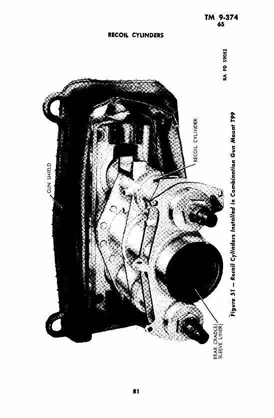
REAR
C
RAD
LE)
SLEE
VE L
INER
J
n O ft r- z
RA P
D 59
082
a?Fi
gure
51
— R
ecoi
l Cyl
inde
rs I
nsta
lled
in C
ombi
natio
n G
un M
ount
T99

.RE
CO
IL P
ISTO
N R
OD
NU
T
CAS
KET
(RE
CO
IL C
YLI
ND
ER
) P
LU
G (
fKO
NT
END)
K>
PIST
ON
R
OD
C
OU
PLI
NG
NU
T
REC
OIL
CY
LIN
DE
R
PLU
G <
«**
END;
REC
OIL
PI
STO
N
RO
D
BU
SH
ING
FO
LLO
WER
O CO
O
1 {R
ECO
IL C
YLI
ND
ER
I C
OVE
R (
«AW
LOC
KWAS
HER
REC
OIL
CY
LIN
DE
R L
OC
KIN
G N
UT
REC
OIL
CY
LIN
DE
R
CO
VER
iiu
rm E
ND/
n
O
RA P
D 59
233
Figu
re 5
2 —
Rec
oil
Cyl
inde
r A
ssem
bly

CO
UN
TER
RE
CO
IL
BUFF
ER
CA
SK
ET
t REC
OIL
CY
LIN
DE
R P
LUG
(«O
NT F
ND;
f REC
OIL
CY
LIN
DE
R O
UTE
R S
PR
ING
'RE
CO
IL C
YLI
ND
ER
IN
NE
R S
PR
ING
REC
OIL
PIS
TON
RO
D N
UTt
PIN
-BF
DX
4AP
i
CO
PPER
G
ASKE
TLO
CK
WAS
HER
PIS
TON
RO
D
CO
UN
TER
RE
CO
IL B
UFF
ER
REC
OIL
CY
LIN
DE
R S
LEEV
E
CO
PPER
GA
SK
ET
REC
OIL
CY
LIN
DE
R C
OVE
R
SAFE
TY N
UT
RE
CO
IL C
YLI
ND
ER
FIL
LIN
G
PLU
G C
AS
KE
TJR
ECO
IL C
YLI
ND
ER
LO
CK
ING
NU
TR
ECO
IL
CY
LIN
DE
R)
PLU
G
REC
OIL
S
PR
ING
SE
AT'
RE
CO
IL C
YLI
ND
ER
CO
VER
IK
A»/
CO
PPER
CA
SK
ET
'
50 §\
PIS
TON
R
OD
Q
^CO
UP
LIN
G
NU
T
P
US
CR
EW
- O
JBC
KX
1DF
S
FIBE
R W
AS
HE
R
[RE
CO
IL
PIS
TON
D B
US
HIN
G
^FO
LLO
WER
(RE
CO
IL
PIS
TON
JR
OD
B
US
HIN
G
(RE
CO
IL P
ISTO
N
( R
OD
PA
CK
ING
RA
PD
6509
4
2 85
f>fi
gu
re 5
3 —
90-
mm
Gun
Mou
nt T
8 (M
4) a
nd C
ombi
natio
n G
un M
ount
s T9
9, T
99E
I, an
d T9
9E2

TM 9-374 65
90-MM GUN M3 MOUNTED IN COMBAT VEHICLES
b. Check Oil Level in Recoil Cylinder. To check oil level, de press gun 5 degrees and remove the top plug at the rear of each cyl inder. The oil level in the cylinder should reach bottom of hole. If oil level does not reach this level, fill until level is reached. Re place plugs. Recoil mechanism uses special recoil oil. Care must be taken not to use any other recoil oil than that prescribed. Special recoil oil will be used for all temperatures.
84

TM 9-374 66-69
PART FOUR - AUXILIARY EQUIPMENT
Section XXII
GENERAL
66. SCOPE.a. Part Four contains information for the guidance of the per
sonnel responsible for the operation of this equipment. It contains only the information necessary to using personnel to properly identify, connect, and protect such auxiliary equipment while being used or transported with the main equipment. Detailed instructions per taining to auxiliary equipment are contained in Technical Manuals.
Section XXIII
AMMUNITION
67. GENERAL.a. Ammunition for the 90-mm Gun M3 is issued in the form of
complete rounds of fixed ammunition. The term "fixed" signifies that the propelling charge is not adjustable and that the round is loaded into the gun as a unit. Fixed ammunition is characterized by the rigid crimping of the cartridge case to the projectile. A com plete round consists of all the ammunition components required to fire the weapon once. As shipped, high-explosive shell for this gun are fitted with a point-detonating fuze to explode the shell on impact. Explosive-filled armor-piercing projectiles have a base-detonating fuze. All armor-piercing projectiles are fitted with a tracer for observation purposes.
68. FIRING TABLES.a. Firing data for the Gun M3 on tank and motor carriage mounts
was not available at the time of publication. An index of Firing Tables is maintained in FM 21-6.
69. CLASSIFICATION.a. The ammunition available for use in this gun consists of the
following types, classified according to the kind of projectile: high- explosive, armor-piercing-capped, armor-piercing, practice, blank, and drill (dummy).
b. The high-explosive projectile is a thin-walled shell containing a relatively large charge of high-explosive, intended for fragmentation
85

TM 9-374 69-70
90-MM GUN M3 MOUNTED IN COMBAT VEHICLES
and blast effect. For use in the 90-mm Gun M3, it is fitted with a selective action fuze (M48 series), providing superquick action for surface burst or short delay action upon ricochet, or for mining effect. When assembled to the 90-mm high-explosive shell, the fuze is classi fied boresafe (detonator-safe) since the explosive train of the fuze and booster is so interrupted that, prior to firing and while the shell is still in the bore of the gun, premature functioning of the bursting charge is prevented should any of the more sensitive elements, primer and/or detonator, malfunction.
c. The armor-piercing-capped projectile is a comparatively thick- walled shell with a small charge of high-explosive, intended primarily for perforation of armor and explosive effect behind the plate. It is fitted with a Delay-action Base-detonating Fuze (M68) which is not considered boresafe. A tracer element incorporated in the base of the fuze operates independently of the fuze mechanism to provide a luminous trace for observation purposes during the first stages of the projectile's flight.
d. The armor-piercing projectile is an uncapped solid shot of the monobloc type. It has a tracer incorporated directly in its base which functions like that in the fuze of the capped armor-piercing projectile.
e. Practice ammunition for the 90-mm gun is similar to the high- explosive service round, except that the projectile has an inert filler and is fitted with a dummy or inert service fuze for use in target practice.
f. Blank ammunition contains no projectile, and is provided for use in the 90-mm gun primarily for simulated fire.
g. The drill cartridge is a completely inert assembly of malleable iron or bronze fitted with a dummy fuze. It is provided for practice in servicing the piece.
70. IDENTIFICATION.a. General. Ammunition and ammunition components are com
pletely identified by the painting and marking (including an ammu nition lot number) which appear on all original packing containers and, when practicable, on the items themselves. For marking on the items themselves, see the paragraphs immediately below; for marking on containers, see paragraph 74 b.
I). Mark or Model. To identify a particular design, a model designation is assigned at the time the design is classified as an adopted type. This model designation becomes an essential part of the standard nomenclature of the item and is included in the marking of the item. The present system of model designation is to use the letter "M" followed by an arabic numeral. Modifications are indi-
86

TM 9-374 70
AMMUNITION
cated by adding the letter "A" and its appropriate arabic numeral. Thus, "M48A1" signifies the first modification of an item for which the original model designation was "M48."
c. Ammunition Lot Number. At the time of manufacture, every item of ammunition is assigned a lot number in accordance with per tinent specifications. When practicable, this lot number is stamped on the item itself. In addition, an ammunition lot number is assigned to the complete round. This ammunition lot number is stamped or marked on each round and on all packing containers. It is required for all purposes of record, including reports on condition, functioning, and accidents in which the ammunition is involved. To provide for the most uniform functioning, all of the rounds of any one ammuni tion lot are made up of single lots of components. To obtain the greatest accuracy in firing, successive rounds should be from the same ammunition lot.
d. Weight-zone Marking. Small variations in weights occur dur ing the manufacture of different lots of high-explosive shell. When required, such shell are grouped in weight zones so that appropriate ballistic corrections provided in Firing Tables may be applied for the variations. In the 90-mm caliber, the weight zone of the projectile is indicated thereon by squares in the same color as the marking, with a prick punch mark in each. One, two, three, or more, such squares are marked on the shell, depending on the weight of the loaded pro jectile. Two squares indicate "standard" or '"normal" weight. For shell so marked, no weight corrections are necessary. The canister and armor-piercing projectiles do not have weight-zone markings.
e. Marking. The above, and other essential information, is marked on the 90-mm rounds as follows:
(1) ON THE PROJECTILE (STENCILED). Caliber and type of cannon in which fired. Kind of explosive filler, "TNT," "EXP. D," etc., when explosive filler
is present. Model of projectile."WITH TRACER," when tracer is present. Weight-zone marking, when required. Lot number of filled projectile. Ordinarily, the projectile lot number
is not required after the complete round is assembled. Hence, it isstenciled below the rotating band, in which position it is hiddenfrom view by the neck of the cartridge case.(2) ON THE CARTRIDGE CASE:
Ammunition lot number and loader's initials (stenciled). The ammu nition lot number will have an "X" suffix when the round is assem bled with a steel cartridge case.
87

TM 9-374 70-71
90-MM GUN M3 MOUNTED IN COMBAT VEHICLES
Model of projectile (stenciled).Caliber and model of cartridge case (stamped in the metal). The
model number will have a "Bl" suffix when the case is made of steel.
Cartridge case lot number, initials or symbol of cartridge case manu facturer, and year of manufacture (stamped in the metal).(3) ON THE POINT FUZE (STAMPED IN THE METAL).
Type and model of fuze.Loader's lot number, including loader's initials. Year of manufacture. Action; that is "SQ," "DELAY." Since the Fuze M48A2 may have
0.05- or 0.15-second delay, depending on the lot, the length of delayin seconds (".05-SEC," or ".15-SEC," as applicable) is stamped onthe fuze following the model number.
f. Painting. Artillery projectiles are painted primarily to prevent rust. Secondary purposes are to provide, by the color, a ready means of identification as to type, and for camouflage. The color scheme is: High-explosive, and armor-piercing with explosive
filler .................................................. Olive drab, marking in yellow.Armor-piercing without explosive filler.......... Black, marking in white.Practice ............................................................ Blue, marking in white.Drill (dummy) .................................................... Unpainted when of
bronze; otherwise black, marking in white.
71. CARE, HANDLING, AND PRESERVATION.a. General. Ammunition is packed to withstand conditions or
dinarily encountered in the field. Care must be observed to keep packing containers from becoming broken or damaged. All broken containers must be repaired immediately, and careful attention given to the transfer of all markings to the new parts of the container. When it is necessary to leave ammunition in the open, raise it on dunnage at least 6 inches from the ground, and cover it with a double thickness of tarpaulin. Suitable trenches should be dug to prevent water from running under the pile.
b. Since explosives are adversely affected by moisture and high temperature, due consideration should be given to the following:
(1) Do not break the moisture-resistant seal until ammunition is to be used. Ammunition removed from the airtight container, par ticularly in damp climates, is apt to corrode, thereby causing the ammunition to become unserviceable.
88

TM 9-374 71-73
AMMUNITION
(2) Protect the ammunition, particularly fuzes, from sources of high temperature, including the direct rays of the sun. More uniform firing is obtained if the rounds are at the same temperature.
c. Ammunition should be protected from mud, sand, dirt, and water. If the rounds become wet or dirty, they should be wiped off at once. Verdigris or corrosion should be wiped off. Ammunition should not be polished, however, to make it look better or brighter.
<1. Explosive ammunition must be handled with appropriate care at all times. The explosive elements in primers and fuzes are par ticularly sensitive to undue shock and high temperature.
e. Blank ammunition with loose or broken closing cap will not be used or fired, but will be reported to the Ordnance officer for dis position.
f. Rounds prepared for firing, but not fired, will be returned to their original condition and packings, and appropriately marked. Such ammunition will be used first in subsequent firings in order that stocks of opened packings may be kept at a minimum.
g. Do not handle duds. Because their fuzes are armed, and hence, extremely dangerous, duds will not be moved or turned, but will be destroyed in place in accordance with TM 9-1900.
72. AUTHORIZED ROUNDS.a. The ammunition authorized for use in the 90-mm Gun M3 is
listed in table I together with essential data, and is illustrated in fig ures 54 to 58. Standard nomenclature is used in the listing of author ized rounds. Its use is mandatory for all purposes of record, except where the use of the Ammunition Identification Code (A.I.C.) symbol is prescribed to facilitate requisitioning and reporting in the field. Each complete round of fixed ammunition in a specific packing is assigned an A.I.C. symbol. These symbols are published in ORD 11 SNL's.
73. PREPARATION FOR FIRING.a. All rounds are ready for use upon removal of packing material
except high-explosive rounds, the fuzes of which must be adjusted for the desired action as described below.
b. P.D. Fuzes M48 and M48A2. For setting purposes, all fuzes of the M48 series have a slotted "setting sleeve" and two registration lines. The line parallel to the axis is marked "SQ" (superquick); the other at right angles thereto is marked "DELAY." As shipped, the fuze is "SQ." To obtain delay action it is only necessary to turn the "setting sleeve" so that the slot is alined with "DELAY." A black powder pellet incorporated in the delay action train provides for the
89

90-MM GUN M3 MOUNTED IN COMBAT VEHICLES
TM 9-37473
90-MM GUh
«/»3uUI>
COMBA1
ZOQ uiZ
ii
si 2 |
go>0!O u.
ZOpZs
^<SN5 OX5<
i i»Z u >3OWOCs< § S .
1
1 s ns ° =0
liu, i
HI ^r jHi*s
§ --i ?c8 j'=-UI1- III
i iso 5 =" S
aiOfl(
UI1- III
S8u.oUI
iUI
OZa m25HIA
1
I!IM
•H COt^
XZ
-io'SwQ
*ocs
HgH
Ol eseocs
TfTC*-»
ro Ol
,P.D.,M48A2,
WN!»>S
;It*. .SJ- u'-SX .:SJ •o ?u >«X O * 0
3*w 01X wW
fH
^ t^
X ZIII
*>o-«wQ
SC*l
HZH
Ol cs
cs
XJ- *r*^«
sH
<«•
r*
TTsd&,'
Sggl:•!s s2 >;. o«•rf*v»*§d-8SoK M W
vHCO t-C
XZ
JS*>,5^wQ
*ocs
HZH
Oi es<*lcs
?r^
S
CO1QoiWN
£ ^X Z^r i-sw X•s§ * s>ilw
eo t-;
X Zfa
*volcaQ
*0CS
HZH
Oi csfftcs
TfTft^«
CO OiT-4
f
00Tfs ciPH'
UN
1
r-*
Sw X«"sx a* adi Ss0}
«r^
XZ
>!
?o
Q^
U
fH
es
* esto
irtr^
t
(H, w/FUZE, s....... .................
Z G
fixed, A.P.C., M82, d TRACER, 90-mm gu
H Ss« Ds1*
*H COt^
Xto
&s**CI
Q*U
-es
TfesCOm
V*r*es*
Q «W N 5 toS
es" M2 cs ai\•rftf18S'S•-1 -o H C (J «
gsis0,
^4 « t-C
XguI
4J
Z
o*Mes
TI CS00
scs
w/TRACER,
X Ze*00sd(X<•8 £s§paO £a i51 !r
90

AMMUNITION
TM 9-374 73
1Meo t-:
S 2 to
V
|*5
Vco2
oTTm c*
*CMCOfO
scvTf
K U U«H\
<>f00s(jft' <•8M
1C
W „PROJECTIL 90-mm gun:
2
E2
§2
VeoZ
o*foC*I
IO r~<N«
se*i*
E\
O Ot
KS<KH ^
SZtC (N,
Sa,'<•o"uw 1C
H g 0 3BC MCO
«-t« l>
11Z
S|Z
o»fOff«
l/> t~esm
•«• oCNI*
iM
EEoOl
K UUKH ^rC f*go;<•o"s
1C
H
g W
v4« »-
Z
ti'tM
44-
t£
I-H
O^ POCH
?tx<o
*t o es»
Szj- S
t^ 3S ME•o'f! §— *-
«fu «
SHELL, fixed, practice, in w/FUZE, dummy or inert,
*«^N
sto
t0>Cw
++
tII-H
O*rt CM
*^(^fO
TfO«^i*
« N
toXS^t^s
to•0 3^aIE
E
SHELL, fixed, practice, inert dummy, or inert, M — ,f 90-
e.Sc3
<
Jt
|•
VI
1Jd S
»oe-tN.
6««O 00
—
c3ws
AMMUNITION, blank, 90-m
S£
4*>E a 2
o
tig
H4
**t-'
tO
in o!m
CN"
«tTj-
2>;EE3•o
WNSto
CARTRIDGE, drill, M12, w/ 90-mm guns ...........................
.!1is Ia |
H!1 1 s,f IfS cC w
CN
^>^-
S >,E
1'a (if8 H
S § g 1 & u|| ? S
•8 8'g 8- s "B St -2 » >;i 1 i I'S °? * |£ I 3a. 1 1 -oJi £ " W 5 £ K g
h
o&
0011
•o "8
1 1
A .P . — armor-piercing A . P . C . — armor- piercin g-ci
B.D. — base-detonating
* — 0.05-second delay
f — May be either an inert service f
£ — traded to required weight.
§ — Approximate
91

w
CA
LIB
ER
OF
CA
NN
ON
AN
D M
OD
EL
OF
CA
RTR
IDG
E C
ASE
WE
IGH
T ZO
NE
MA
RK
ING
—
AM
MU
NIT
ION
LO
T N
UM
BE
R
CA
LIB
ER
AN
D T
YPE
OF
CA
NN
ON
M
OD
EL
OF
SHEL
L K
IND
OF
FILL
ER
CA
RTR
IDG
E C
ASE
LOT
NU
MB
ER
M
OD
EL
OF
SHEL
L
MA
NU
FAC
TUR
ER
'S I
NIT
IALS
AN
D Y
EA
R O
F M
AN
UFA
CTU
RE
- 37.
44 M
AX
. -
OLI
VE
DR
AB •
(MA
RK
ING
IN
YE
LLO
W)
O u I Z rv
O OBRA
PD
6120
4
O
m
Figu
re 5
4-H
.E.
Fixe
d Sh
elf M
71,
With
P.O
. Fu
ze M
48A2
, SO
and
0.0
5-se
cond
Del
ay,
for
90-m
m G
uns

TM 9-374 73-74
AMMUNITION
delay action. The setting may be made or changed at will with the screwdriver end of Fuze Wrench M7A1, or similar instrument at any time before firing. This can be done in the dark by noting the posi tion of the slot.
74. PACKING.a. Data. Service and practice rounds have been packed in in
dividual fiber containers, in turn packed in a wooden box holding two or four rounds. In addition, a new type of packing has been developed which consists of a metal packing container holding one round. Data given below is considered representative for estimating volume and weight requirements; complete data is published in ORD 11 SNL's P-5, P-7, and P-8.
Over-all Dimensions of Packing Container(ft)
4-rd. box: 3.64 x 1.08 x 1.08 ................
2-rd. box: 3.65 x 1.08 x 0.61 ................
Metal cntr.: 3.61 x 0.51 x 0.51 ................
Weight (Ib)
236
129
Volume (eu ft)
4.24
2.40
0.94
b. Marking for Shipment.(1) Packings for shipment are marked as follows:(a) Name and address of destination or port officer, preceded by
word "To."*(b) Name and address of ultimate consignee, preceded by word
"For."*
(c) List and description of contents. "NH" will be stamped on packing boxes and sealing strips of containers containing NH pro pellent powder. Packings not so marked may be assumed to contain FNH-loaded rounds.
(d) Ammunition Identification Code (A.I.C.) symbol, as pub lished in SNL's.
(e) Gross weight in pounds, displacement in cubic feet.(f) The number of the package or shipping ticket.* (£) The letters "U.S." in several conspicuous places (not man
datory).(h) Order number or contract number. (i) Ordnance insignium and escutcheon.
*May be omitted on individual package in carload shipments of packages of standard weights and dimensions containing standard quantities.
93

TM 9-374 74
90-MM GUN M3 MOUNTED IN COMBAT VEHICLES
94
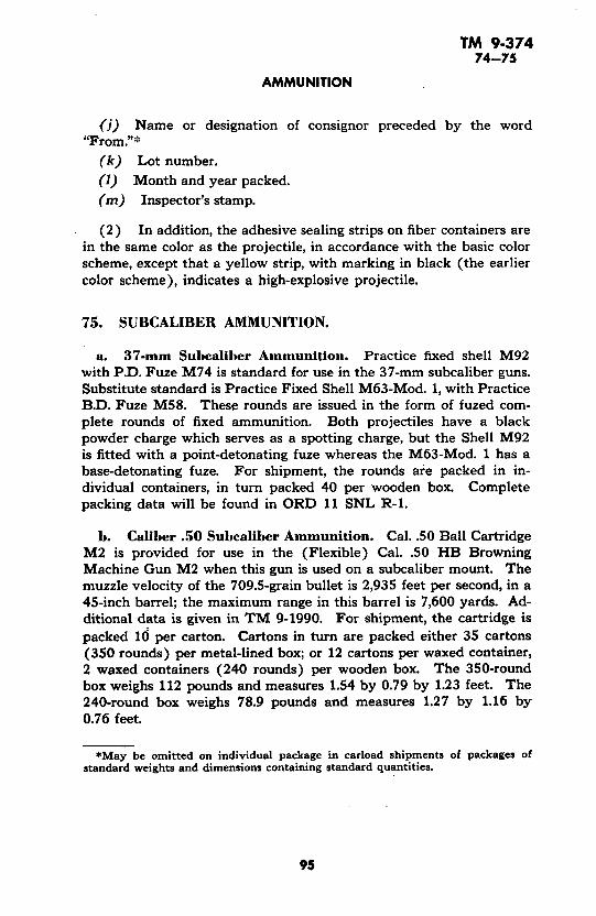
TM 9-374 74-75
AMMUNITION
(j) Name or designation of consignor preceded by the word "From."*
(k) Lot number.(1) Month and year packed. (m) Inspector's stamp.
(2) In addition, the adhesive sealing strips on fiber containers are in the same color as the projectile, in accordance with the basic color scheme, except that a yellow strip, with marking in black (the earlier color scheme), indicates a high-explosive projectile.
75. SUBCALIBER AMMUNITION.
a. 37-mm Subcaliber Ammunition. Practice fixed shell M92 with P.D. Fuze M74 is standard for use in the 37-mm subcaliber guns. Substitute standard is Practice Fixed Shell M63-Mod. 1, with Practice B.D. Fuze M58. These rounds are issued in the form of fuzed com plete rounds of fixed ammunition. Both projectiles have a black powder charge which serves as a spotting charge, but the Shell M92 is fitted with a point-detonating fuze whereas the M63-Mod. 1 has a base-detonating fuze. For shipment, the rounds are packed in in dividual containers, in turn packed 40 per wooden box. Complete packing data will be found in ORD 11 SNL R-l.
b. Caliber .50 Subcaliber Ammunition. Cal. .50 Ball Cartridge M2 is provided for use in the (Flexible) Cal. .50 HB Browning Machine Gun M2 when this gun is used on a subcaliber mount. The muzzle velocity of the 709.5-grain bullet is 2,935 feet per second, in a 45-inch barrel; the maximum range in this barrel is 7,600 yards. Ad ditional data is given in TM 9-1990. For shipment, the cartridge is packed 10 per carton. Cartons in turn are packed either 35 cartons (350 rounds) per metal-lined box; or 12 cartons per waxed container, 2 waxed containers (240 rounds) per wooden box. The 350-round box weighs 112 pounds and measures 1.54 by 0.79 by 1.23 feet. The 240-round box weighs 78.9 pounds and measures 1.27 by 1.16 by 0.76 feet.
*May be omitted on individual package in carload shipments of packages of standard weights and dimensions containing standard quantities.
95

WE
IGH
T Z
ON
E M
AR
KIN
G <
CA
LIB
ER
AN
D T
YP
E O
F C
AN
NO
Ns
-CA
LIB
ER
OF
CA
NN
ON
AN
D M
OD
EL
OF
CA
RTR
IDG
E C
ASE
^MU
NIT
ION
LO
T N
UM
BE
R
OD
EL
OF
SH
ELL
C
AR
TRID
GE
CAS
E LO
T N
UM
BE
RK
IND
Qf
F|L|
ER
MO
DE
L O
F S
HE
LL
EAR
OF
MA
NU
FAC
TUR
E- 3
7.44
MA
X.
RA
PD
2676
7
Figu
re 5
7 - In
ert-
load
ed F
ixed
Pra
ctic
e Sh
ell
M71
, W
ith D
umm
y Fu
ze M
73,
for
90-m
m G
uns
9 o o c
5 "2
DE
SIG
NA
TIO
N
OF
DR
ILL
CA
RTR
IDG
E
MA
NU
FAC
TUR
ER
'S
INIT
IALS
AN
D
YE
AR
O
F M
AN
UF
AC
TU
RE
RA
PD
2677
0
Figu
re 5
8 - D
rill
Car
trid
ge M
l2,
With
Dum
my
Fuze
M44
A2,
for
90
-mm
Gun
s
O
O OB

TM 9-374 76
Section XXIV
SIGHTING AND FIRE CONTROL EQUIPMENT
76. ARRANGEMENT OF SIGHTING AND FIRE CONTROL EQUIPMENT.
a. Medium Tanks T25E1 and T26E1.
(1) The on-carriage sighting and fire control equipment for the 90-mm Gun M3 used in these tanks includes the Telescope Mount T90 with Telescope M71C and Instrument Light M33, or Telescope M70P with Instrument Light M32 or M39C; the Periscope M10F with periscope mount and Instrument Light M30 (Periscope M8A1 with Telescope M80D (T121) and Instrument Light M30 is fur nished as a spare) for those tanks which have no bulge in their tur rets; the Periscope M10N with periscope mount and Instrument Light M30 (Periscope M4A1 with Telescope M77F is furnished as a spare) for those tanks which have a bulge in their turrets; and the Elevation Quadrant M9 with Instrument Light M30.
(2) The Periscope M6 is furnished for observation from within the tank by the driver and assistant driver.
(3) The off-carriage fire control equipment for these tanks in cludes the Binocular M13, the Gunner's Quadrant Ml, the Azimuth Indicator M18 or M20, and the Fuze Setter M14.
b. 90-mm Gun Motor Carriage T71 (M36).
(1) The on-carriage sighting and fire control equipment for the 90-mm Gun M3 and 90-mm Gun Mount T8 (M4) used on the 90-mm Gun Motor Carriage T71 (M36) includes the Telescope Mount T92 with Telescope M76F and Instrument Light M33, or Telescope M70P with Instrument Light M32 or M39C; Telescope Mount T104E1 with Panoramic Telescope M12 and Instrument Light M31; and the Elevation Quadrant M9 with Instrument Light M30.
(2) The Periscope M6 is furnished for observation by the driver and assistant driver of the vehicle.
(3) The off-carriage fire control equipment for the carriage is the same as for the medium tanks described above.
97

TM 9-374 76
90-MM GUN M3 MOUNTED IN COMBAT VEHICLES
is
N
I
ft. £3a

TM 9-374 77
SIGHTING AND FIRE CONTROL EQUIPMENT
RA PD 31454
Figure 60 — Reticle Pattern for Telescope M71C
77. TELESCOPE M71C. a. Description.(1) The Telescope M71C (fig. 59), which is a straight tube tele
scope, is mounted in the Telescope Mount T90, on the right-hand side of the gun cradle. The telescope is a 5-power erect image instrument having a field of view of 13 degrees. Windows above the reticle pro vide for illumination of the reticle pattern.
(2) The reticle pattern (fig. 60) is based upon the data from Firing Table 90-C-2, Part 2A, and is correct for the 90-mm Gun M3 with Armor-piercing-capped Projectile M82; muzzle velocity of 2,670 feet per second; minus 0.2-mil vertical jump; plus 0.7-mil side jump at zero range; and plus 2.0 mils side jump and drift at 4,000 yards range. The cross in the pattern represents zero range and zero deflection.
99

TM 9-374 77
90-MM GUN M3 MOUNTED IN COMBAT VEHICLES
U ILU LU
o o
95-
£ < Q§ ^<a:
oi
§ 1/1op
~1
§iCL
1u
o
IUSTMENT
<IDEX
Q^ <Q
5<F3
IS
c^
i'Z
iQC
o:
1
IUSTMENT AND INDEX
RA PD 31
2*;e s§feg >t
c o
<ua. o
O)
100

TM 9-374 77
SIGHTING AND FIRE CONTROL EQUIPMENT
The cross is used for bore sighting. The broken line extending down ward below the cross is at a slight angle to, and offset from the vertical center of the reticle to compensate for drift and lateral jump. Each part of the broken line represents an interval of 200 yards range, and serves as a guide when laying the gun for a range falling within a 400- yard interval. The broken horizontal lines below the cross represent 400; 800; 1,200; 2,000; 2,400; 2,800; 3,200; 3,600; 4,000; and 4,400 yards range. The bottom of the broken line extending downward be low the cross represents 4,600 yards range. The range marks are numbered 8, 16, 24, 32, 36, and 40. Each horizontal line and each horizontal space represents a deflection or lead of 5 mils. The in scription "90-M82" at the upper edge of the reticle indicates the ammunition. The number "7672267" at the lower edge of the reticle is the part number of the reticle.
b. Telescope Removal and Replacement.(1) Remove the lamp bracket, with the hand, from the top of
the telescope.(2) Loosen the wing nut and round out on the left side of the
telescope clamp (fig. 61) and slide the telescope backwards. When replacing the telescope, insert the front of the telescope through the front holder from the rear, and push the telescope forward until the locating pin on the under side of its rear collar (fig. 59) engages the locating slot in the rear holder. Moderate force is necessary to push the telescope into place, as the spring-loaded plunger in the front holder bears down on the telescope.
(3) Close the rear clamp and secure the telescope in place by tightening the round nut and wing nut. Attach the lamp bracket to the telescope.
c. Operation.(1) To operate the Telescope M71C for direct laying of the
90-mm Gun M3 against moving targets, bring the image of the target to the point on the reticle representing the required range and deflec tion by rotating the elevating handwheel and traversing the turret. The gunner's eye should be approximately 1 1A inches from the tele scope eyelens when observing.
(2) For night observing, turn the rheostat knob on the end of the instrument light until the reticle pattern is seen clearly.
d. Adjustments. The telescope and gun are bore sighted as de scribed in paragraph 87 at the time the telescope mount is assembled to the gun mount, and no further adjustments other than verification of this adjustment should be necessary by the using arm.
e. Care and Preservation.(1) The Telescope M71C is a precision optical instrument and
care should be exercised in handling to prevent damaging or disturb-
10T

TM 9-37477-78
90-MM GUN M3 MOUNTED IN COMBAT VEHICLES
ing the optical system. Be careful to avoid denting or otherwise damaging the collars and spherical bearing surfaces of the telescope when removing and replacing it in the mount.
(2) The spherical bearing surfaces and collars of the telescope should be kept coated with a light film of grease to prevent rust. Wipe all dust and grit from locating surfaces before placing the tele scope in the mount.
(3) Keep the illumination windows over the reticle '-.lean.(4) Refer to paragraph 37 for general care and preservation per
taining to sighting equipment.
78. TELESCOPE MOUNT T90. a. Description.(1) The Telescope Mount T90 (fig. 61) supports the Telescope
M71C in a front and rear holder. The front holder is fixed, but the rear holder is adjustable with lateral and vertical adjusting mech anisms for bore sighting the mount and telescope. The amount of the adjustment is registered on scales and micrometers. The lateral ad justment scale which is on the right side is graduated in reference units approximating mils, from 0 to 20 either side of 0, and marked 0, 10, 20. Arrows and the letters "L" and "R" (left and right) indi cate the direction of the adjustment. The lateral adjustment microm eter, which is on the left side, is graduated for reference only in ap proximate mils, and marked 0, 1, 2, 3, 4, in both directions. Arrows and the letters "L" and "R" indicate the direction of the adjustment. The sum of the scale and micrometer readings is the amount of the adjustment in units. The vertical adjustment scale and micrometer are graduated in the same manner as the lateral adjustment scale and micrometer with the exception that the direction of the adjustment is indicated by the letters "EL" and "DEP" (elevation and depression). No means are provided for setting off deflection or elevation angles; this is accomplished with the graduated reticle in the telescope.
(2) The headrest which is mounted on the right-hand side of the gun cradle is adjustable to suit the position of the gunner's head. The clamp for the Instrument Light M33 is secured to the left side of the telescope mount. For description of the instrument light, refer to paragraph 79.
b. Operation.(1) Adjust the headrest for the gunner's eye. To move the head
rest vertically, loosen the two bolts between the mounting and sup porting bracket, and move either up or down to suit the gunner. Tighten the bolts. To move the rest in a horizontal position, loosen the bolt holding the rest, and slide the rest either in or out, in order
102

TM 9-374 78
SIGHTING AND FIRE CONTROL EQUIPMENT
CAP-
TUBE
RHEOSTAT KNOB
LAMP BRACKET
LEAD WIRE BODY
• LEAD WIRE
RA PD 28951
Figure 62 — Instrument Light M33
to secure the fullest field of view. Tighten the bolt and check to see that neither adjustment has slipped.
(2) For operation of the lateral and vertical adjusting mech anisms, refer to paragraph 87 on procedure for bore sighting.
c. Adjustments.(1) Aside from the adjustments associated with the operation
described above, and the adjustment of the micrometers to read zero when their respective scales read zero, described below, no adjust ments are to be made by the using personnel,
(2) If a micrometer does not register zero when its scale reads zero, loosen the clamping nut in the end of the micrometer knob and, while holding the knob to prevent movement of the scale, slip the micrometer until it registers exactly zero. Tighten the clamping nut.
d. Care and Preservation.(1) Exercise care to prevent denting or otherwise damaging the
locating surfaces of the mount. See that locating surfaces are kept clean and covered with a light film of grease.
(2) Before assembling a telescope to its mount, wipe all dust and grit from the locating surfaces of both the mount and telescope.
103

TM 9-374 78-79
90-MM GUN M3 MOUNTED IN COMBAT VEHICLES
(3) Keep all oil, grease, and dirt from the forehead pad of the headrest.
(4) Keep the telescope mount covered when not in use.(5) Refer to paragraph 37 for general care and preservation in
structions pertaining to the equipment.
79. INSTRUMENT LIGHT M33.a. Description. The Instrument Light M33 consists principally
of a body tube and rheostat connected to a lamp bracket by a lead wire and lead wire body. Two ! 1/2-volt dry-cell batteries are con tained in the body tube. A 3-volt electric lamp is contained in the lamp bracket. A rheostat knob on the end of the body tube turns the light on or off and regulates the intensity of the illumination. The body tube is held in a clamp attached to the left side of the telescope mount. The lamp bracket engages a slot in the top of the telescope over the reticle.
b. To Remove Instrument Light M33 From Telescope and Mount.
(1) With the fingers, disengage the lamp bracket from the top of the telescope.
(2) Loosen the thumb nut on the clamp which secures the body tube, until the tube can be slid out of the clamp.
(3) When replacing the lamp bracket on the telescope, be sure the bracket is fully engaged in the slot and is positioned by the spring and ball detent.
c. To Replace Batteries. Turn the cap on the end of the body tube to disengage the two bayonet slots in the tube, and pull off the cap. Remove the two batteries. When replacing the batteries in the body tube be sure they go back in the same position as when removed. See that the pins in the cap engage the bayonet slots in the body to assure a tight contact with battery terminals.
d. To Replace Electric Lamp. Unscrew the lamp bracket from the lead wire body. Unscrew the 3-volt electric lamp from the socket.
e. Operation. Turn the rheostat knob on the rear end of the body tube until the reticle pattern as observed through the telescope is clearly visible.
f. Adjustments. No adjustments, other than those described above, are permitted by the using arm. If the instrument light fails to provide the required amount of illumination after checking the batteries, lamp, and windows, turn the instrument in for repairs by qualified Ordnance maintenance personnel.
104

TM 9-374 79
SIGHTING AND FIRE CONTROL EQUIPMENT
,CAP RHEOSTAT KNOB
LEAD WIRE
RA PD 31680
Figure 63 - Instrument Light M30
CLAMPGUARD
TOGGLE SWITCH
TUBE CAP
HOUSING ILLUMINATING
TUBE
EYEBOLTTHUMBNUT
HAND LIGHT CLIP
HAND LIGHT CAP
ILLUMINATING TUBE'
RA PD 31681
Figure 64 — Instrument Light M31
g. Care and Preservation.(1) Do not turn the rheostat knob so that the reticle is exces
sively illuminated. Just enough illumination to bring out clearly the reticle pattern is all that is necessary. Excessive illumination serves no purpose and will shorten the life of the batteries.
(2) . Remove the cells from the body tube whenever the instru ment light is not to be used for long periods, otherwise the chemical reaction set up in them will damage the tube.
(3) Keep the instrument light clamp tight.(4) Keep the contact surface of the lamp bracket covered with
105

TM 9-374 79
90-MM GUN M3 MOUNTED IN COMBAT VEHICLES
NOTATION LABEL
HEAD
LATCH
MOUNTING STUD
DIOPTER SCALE
PLUG RECEPTACLE (S/X.POWER;•EYE SHIELD
-INSTRUCTION PLATE
-OBSERVATION WINDOW
RA PD 31451
Figure 65— Periscope A1TOF —Right Rear View
106

TM 9-374 79
SIGHTING AND FIRE CONTROL EQUIPMENT
COVER
ONE-POWER! I ADJUSTING)-,
KNOBS
LATCH
MOUNTING STUD
(LIGHT •{SOCKET
fONE.POWf «)
[SIX-POWER -(ADJUSTING
KNOBS
PLUG RECEPTACLE(SIX-POVtER)
RA PD 31452
Figure 66 — Per/scope M10F — Left Front View
107

TM 9-374 79-82
90-MM GUN M3 MOUNTED IN COMBAT VEHICLES
a light coating of grease. Occasionally apply a drop of lubricating oil to the spring and ball in the lamp bracket.
(5) Refer to paragraph 37" for general care and preservation in structions pertaining to sighting equipment.
80. INSTRUMENT LIGHT M30.a. Description. The Instrument Light M30 (fig. 63) is identical
to the Instrument Light M33 described above, with the exception that the Instrument Light M30 is provided with a plug assembly instead of the lamp bracket assembly and lead wire body.
81. INSTRUMENT LIGHT M31.a. The Instrument Light M31 (fig. 64), which is a self-contained
instrument light, consists principally of a body upon which is mounteda tube, housing, and a clamp. The tube contains two dry-cell batterieswhich are operated by a toggle switch on the end of the tube. Thebatteries supply current to an electric lamp in the housing, and to ahand light. Light from the lamp in the housing illuminates the reticle,the scales on the panoramic telescope, and the level vials on themount. Light from the hand light is used to illuminate the scale,ndexes, and range drum on the telescope mount. The clamp secureshe instrument light to the Panoramic Telescope Ml2.
b. To Remove Instrument Light M31 From Panoramic Tele scope. Loosen the thumb nut until the clamp can be lifted from the eyebolt. Do not remove the thumb nut. Lift the clamp and remove the instrument light from the telescope.
c. To Replace Batteries. Replace batteries in the same manner as for the Instrument Light M33 which is described in paragraph 79.
d. To Replace Electric Lamps.(1) To replace the electric lamp in the housing, unscrew the lamp
socket in the side of the housing and unscrew the lamp.(2) To replace the electric lamp in the hand lamp, unscrew the
hand lamp cover, and unscrew the lamp.e. Operation. To operate the Instrument Light M31, turn the
toggle switch which is on the end of the tube to the on position.
82. PERISCOPE M10F. a. General.(1) The Periscope Ml OF (figs. 65 and 66) is used for direct
laying against moving targets. The periscope contains two built-in optical systems: a one-power system for use when the general terrain is to be observed and the target is close to the gun, and a six-power system for use when laying on distant targets. The one-power system
108

TM 9-374 82
SIGHTING AND FIRE CONTROL EQUIPMENT
na
I
iUl
O
O
3!0a.
OSI
IS>o
O)
109

TM 9-374 82
90-MM GUN M3 MOUNTED IN COMBAT VEHICLES
may also be used in an emergency to supplant the six-power system.(2) Adjusting mechanisms for bore sighting the periscope, and
electric lamps for illuminating the reticles, are contained in the lower portion of the periscope.
(3) The housing for these parts consists of the periscope head assembly, the periscope body assembly, and the cover assembly.
h. Description.(1) PERISCOPE HEAD ASSEMBLY. The head assembly is secured
to the body of the periscope by a head clamp which is engaged by latches operated by eccentric assemblies in the periscope body (figs. 65 and 66). The arrangement of these parts is such that the head can be removed readily. The head is constructed of plastic material to permit it to shatter into small fragments when struck by a projec tile. Several spare heads are furnished with each periscope. A nota tion label, which is attached to the top of the periscope head, is used for recording bore-sighting adjustments and the serial numbers of the periscope.
(2) PERISCOPE BODY ASSEMBLY. The deflection and elevation adjusting mechanisms which are in the lower portion pi the periscope body are operated by four adjusting knobs: two for the one-power optical system, and two for the six-power optical system. Instructions for their use are engraved on the plate shown in figure 65. An obser vation window for use with the one-power optical system, and an eye piece for use with the six-power system are located in the rear of the periscope body. Light wells in the periscope body provide for illumi nation of the reticles of both optical systems. A 2 8-volt lamp sup plied with current from the tank source illuminates the reticle of the one-power system whenever the system is in use, and a 3-volt lamp supplied with current from the Instrument Light M30 illuminates the reticle of the six-power system for night operation.
(3) RETICLE PATTERN FOR ONE-POWER OPTICAL SYSTEMS. The reticle pattern (fig. 67) for the one-power optical system appears in a horizontal field of view of 42 degrees 10 minutes and in a vertical field of view of 8 degrees 10 minutes. The reticle is graduated for Armor-piercing-capped Projectile M82; muzzle velocity of 2,670 feet per second; minus 0.2-mil vertical jump; plus 0.7-mil side jump at zero range;-and plus 2.0 mils side jump and drift at 4,000 yards range. The graduations are based on data contained in Firing Table 90-C-2, Part 2A. The cross represents zero range and zero deflection and is used when bore sighting. The broken line extending downward below the cross is at a slight angle to, and offset from, the vertical center of the reticle to compensate for side jump and drift. Each part of the broken line represents an interval of 200 yards range, and serves as a guide when laying the gun for a range falling within a 400-yard inter val. The broken horizontal lines below the cross represent 400; 800;
110

TM 9-374 82
SIGHTING AND FIRE CONTROL EQUIPMENTand 1,200 yards range. The bottom of the broken line extending downward below the cross represents 1,400 yards range. The range marks are numbered 8 and 12. Each horizontal line and each hori zontal space represents a deflection or lead of 5 mils. The inscription "90-M82" at the lower edge of the reticle indicates the ammunition.
(4) RETICLE PATTERN FOR SIX-POWER OPTICAL SYSTEM. The reticle pattern (fig. 67) for the six-power optical system appears in a horizontal and vertical field of view of 10 degrees 20 minutes. The reticle pattern is identical to the reticle pattern for Telescope M71C (fig. 2) with the exception that the pattern for the periscope reticle is slightly larger and has the part number "7672807" etched on the reticle at the lower edge.
(5) PERISCOPE HOLDER. The Periscope Ml OF fits in a holder which is mounted in the turret The periscope is provided with mounting studs for positioning it in the holder. The studs fit into slots in the sides of the holder and are held in the slots by two locking levers. The levers work together. They are supported in either one of two positions by spring-loaded plungers. In one position, the peri scope is retracted; in the other position, the periscope is in the viewing position. Only the head of the periscope projects through the tank armor when the periscope is ready for operation. A headrest is mounted on the holder for the convenience of the gunner. Linkage connects the periscope holder to the gun mount so that the periscope moves as the gun is elevated or depressed, thus maintaining the rela tion of the periscope to the gun as it was positioned when bore sighted.
c. Disassembly and Assembly of Periscope M10F.(1) To REMOVE THE PERISCOPE FROM THE HOLDER. When re
moving the periscope from the holder, support the bottom of the periscope with one hand to prevent a sudden drop when the locking levers are released; the levers move together. Push in the rear spring- loaded plunger on the right side of the periscope holder and swing the locking lever down against the front plunger. Slide the periscope down in its holder until its mounting studs rest against the levers. The periscope is now in the retracted position. Force in the front plunger and swing the locking levers down to clear the slot in the body. Pull the periscope straight down until it is clear of the holder. Do not attempt to push or pull the periscope away from the holder until it is entirely clear of the bottom of the holder; otherwise, the periscope head may be damaged.
(2) To REPLACE THE PERISCOPE IN THE HOLDER. To replace the periscope in the periscope holder, see that the locking levers do not block the slots into which the mounting studs must be inserted, and proceed in the reverse order for removal.
(3) To REMOVE THE HEAD ASSEMBLY FROM THE PERISCOPE. Remove the periscope from the holder as described above. With a
111

TM 9-374 82
90-MM GUN M3 MOUNTED IN COMBAT VEHICLES
screwdriver, turn the two eccentrics located on the sides and upper part of the periscope body (figs. 65 and 66) until the head clamp is completely disengaged from the latches. Lift the head from the periscope body.
(4) To REPLACE THE HEAD ASSEMBLY ON THE PERISCOPE. Po sition the head assembly on the top of the periscope body with the window facing the front Turn the eccentrics so that the latches se curely engage the head clamp.
d. Operation.(1) USE OF ONE-POWER OPTICAL SYSTEM. Use the one-power
optical system for general observation of a wide field of view, and for laying the gun on targets close to the tank. This system may also be used in an emergency to supplant the six-power system. See that the tank power source lead is plugged into the light socket (fig. 66). Observing through the observation window, bring the image of the target to the point on the reticle representing the required range and deflection by rotating the elevating handwheel and traversing the turret.
(2) USE OF SIX-POWER OPTICAL SYSTEM. Use the six-power optical system for laying the gun on distant targets. Observing through the eyepiece, focus the eyepiece and bring the image of the target to the point on the reticle representing the required range and deflection by rotating the elevating handwheel and traversing the turret. At night or at other times when the reticle pattern is not clearly visible, turn the rheostat knob of the Instrument Light M30 (fig. 63) which controls the intensity of the illumination until the reticle pattern can be seen clearly.
e. Adjustments.(1) In general, only the specified adjustments and replacements
are to be performed by the using personnel. Tools and parts are furnished for performing these operations. Other replacements and adjustments are the responsibility of the Ordnance maintenance per sonnel, but may be performed by the using personnel, when circum stances permit, within the discretion of the pertinent Ordnance officer.
(2) The connecting link between the gun trunnion and the peri scope holder is adjusted when installed and no adjustment in the field is necessary. Subsequent adjustment, if required, will be made by Ordnance personnel.
(3) The periscope is bore sighted after the periscope holder is installed in the tank. The installation of a new head on the periscope makes it necessary to bore-sight the periscope. The removal of any part of the optical systems and associated adjusting mechanisms from the periscope body is not to be performed by the using personnel.
(4) When bore sighting the periscope, check the adjustment for112

TM 9-37482
SIGHTING AND FIRE CONTROL EQUIPMENTall the spare heads. The bore-sighting adjustments for the various heads (adjusting knob readings) are to be recorded together with the periscope serial numbers in the spaces provided on the notation label of each periscope head.
(5) To replace the 28-volt lamp of the one-power optical system, first remove the tank power source lead (bayonet-type plug) from the socket on the left-hand side of the periscope, by pressing down ward on the plug and turning slightly until free. Then, with the hand, unscrew the socket assembly. Remove the lamp (bayonet-type base) from its socket in the same manner as the plug was removed. Replace with a new lamp, and assemble in reverse order of disassembly.
(6) To replace the 3-volt lamp of the six-power optical system, pull out the plug of the Instrument Light M30 from the housing of the receptacle assembly. The receptacle assembly is screwed into the window assembly in the under side of the periscope. Unscrew the receptacle assembly. The lamp can now be unscrewed from the receptacle assembly. Replace with a new one and assemble in the reverse order of disassembly.
f. Care and Preservation.(1) Keep the periscope in the retracted position with the peri
scope holder cover down, when not in use.( 2 ) Be careful to prevent bumping or denting the periscope body
or its locating surfaces when replacing the periscope in its holder. Exercise particular care in handling the periscope head, as it is made of a breakable plastic material. Never pry against the head.
(3) Always depress the adjusting knobs of the periscope before rotating them, to avoid damage to the detents. Do not force the knobs beyond their limit of motion.
(4) Exposed glass surfaces of windows and lenses should be kept clean and dry. To remove dust from windows or lenses, brush the glass lightly with a clean, camel's-hair brush, then rap the brush against a hard body to knock out dust particles clinging to the hairs. Continue until all dust is removed. For wiping glass surfaces, use only clean lens tissue. Use of cleaning cloths is not permitted. To remove oil or grease from optical surfaces, apply lens-cleaning liquid soap with a tuft of clean lens tissue and wipe dry with clean, dry lens tissue. In the absence of lens-cleaning liquid soap, breathe heavily on the glass surface and wipe it dry with lens tissue.
(5) Do not wipe or touch lenses with the fingers.(6) If excessive dust or moisture collects on the inside of the
windows or mirrors of the periscope, the periscope should be disas sembled and cleaned by Ordnance personnel.
(7) Clean the eyeshield frequently with a soft brush to remove
113

LAM
P S
OC
KET
LEVE
L V
IAL
LEVE
L V
IAL,
CO
VER
OIL
PAD
ELE
VA
TIO
N M
ICR
OM
ETER
ELE
VA
TIN
G K
NO
B
ELEV
ATIO
N M
ICR
OM
ETER
IN
DE
X
ELE
VA
TIO
N S
CAL
E IN
DE
X
ELE
VA
TIO
N S
CAL
E
(REC
EPTA
CLE
/(T
O*
INST
RU
MEN
T LI
GH
T!
LAM
P S
OC
KET
«O 9 o u O c o z r>
O 00
RA
PD
84
747
Figu
re 6
8 —
Ele
vatio
n Q
uadr
ant
M9
— R
ight
Sid
e

TM 9-374 82-83
SIGHTING AND FIRE CONTROL EQUIPMENT
dust, and wipe the eyeshield inside and outside with a damp cloth to keep it clean.
(8) Keep the external locating surfaces of the periscope covered with a light coating of lubricating oil. Moving parts of the periscope are lubricated at assembly, and should not be lubricated in the field except by trained Ordnance personnel.
(9) If moisture condenses on lenses or on the observation win dow, it may be removed by placing the instrument in a warm place. Heat from strongly concentrated sources should not be applied direct ly, as it may cause unequal expansion of parts, thereby resulting in breakage of optical parts or inaccuracies in observation.
(10) Batteries used in the instrument light should habitually be removed whenever the instrument light is not in use. Chemical re action set up on exhausted batteries will damage the battery tube. To remove batteries, remove the cap on the battery tube. The cap is secured by bayonet pins, and is easily removed by pressing the cap inward and then turning slightly until free. When replacing the bat teries in the tube, be sure they go back in the same position as when removed. See that the bayonet pins in the cap engage the slots in the tube to assure a tight contact with battery terminals.
83. ELEVATION QUADRANT M9.a. Description.(1) The Elevation Quadrant M9 (fig. 68) is used for setting off
the required vertical angle to which the 90-mm gun must be elevated or depressed for indirect fire. The angle is registered on two identical scales, one on either side of the instrument, and a micrometer with two indexes, one on either side of the micrometer (50 mils apart). With this arrangement of scales and indexes, the zero of the microm eter can be adjusted for use with either index, depending upon which side of the gun the quadrant is mounted on. The scales are graduated in 100-mil intervals from minus 200 to plus 600 mils, and are num bered from zero to minus 2 and zero to plus 6. The micrometer is graduated in 1-mil intervals from zero to 100 mils, and is numbered every 10 mils from zero to 90. One complete revolution of the eleva ting knob represents 100 mils and moves the scale indexes one com plete division on the scales.
(2) Provision is made for illuminating the two scales, the microm eter indexes, and the level vial.
b. Operation.(1) See that the Instrument Light M30 is plugged in the socket
in the quadrant, and all lamp sockets are screwed in tightly to make contact. Turn the rheostat knob on the end of the body tube until the level vial, and indexes, are clearly seen.
115

TM 9-374 83-84
90-MM GUN M3 MOUNTED IN COMBAT VEHICLES
(2) To aim the gun in elevation, first set off the elevation angle (obtained from the firing table) on the scale and micrometer.
(3) To set in plus angles (elevation), turn the elevating knob counterclockwise until the sum of the scale and micrometer readings equals the desired angle. To set in minus angles (depression), turn the elevating knob clockwise until the scale reading plus the differ ence between the micrometer reading and 100 mils equals the desired angle.
(4) Then elevate the gun with the handwheel until the bubble in the level vial is centered with respect to the graduations on its vial. The gun is now correctly elevated for the particular angle and range.
c. Adjustments.(1) The Elevation Quadrant M9 is adjusted so that the scales
and micrometer read zero, when the axis of the bore of the howitzer is level and the bubble in the level vial is centered, at the time the quadrant is assembled to the gun.
(2) If the adjustment has been disturbed, or it is desired to use the opposite micrometer index, level the bore of the gun with the gunner's quadrant placed on the breechblock. If either of the scales does not register zero when the bubble in the level vial is centered, loosen the two clamping screws at the ends of the scale and shift the scale until it registers zero. To adjust the micrometer to read zero when the scale reads zero, loosen the micrometer clamping nut on the elevating knob and, holding the knob to prevent turning the scale, slip the micrometer to register zero.
(3) To replace a burned-out lamp, loosen the small headless lock ing screw (screwdriver, 0.086-inch blade) which locks the knurled head of the lamp socket. Unscrew the lamp socket. The lamp as sembly comes out with the socket. Replace the lamp assembly.
d. Care and Preservation.(1) Keep the elevation quadrant covered when not in use to pre
vent dust and grit from collecting on the locating surfaces.(2) Keep the cover on the level vial closed when not in use.(3) Keep the felt pads at the ends of the segment pliable by
occasionally applying a few drops of oil.(4) Refer to paragraph 37 for general care and preservation in
structions pertaining to sighting equipment.
84. PANORAMIC TELESCOPE M12, 90-MM GUN MOTOR CARRIAGE T71 (M36).
a. Description.(1) The Panoramic Telescope M12 (fig. 69) has cylindrical
locating surfaces at the top and bottom for centering the telescope in116

TM 9-374 84
SIGHTING AND FIRE CONTROL EQUIPMENT
ELEVATION KNOB
ROTATING HEAD
AZIMUTH WORM] THROWOUT LEVER]
MICROMETER INDEX]
DEFLECTION SCALE
ELEVATION MICROMETER
'PEN SICH7
•AZIMUTH SCALEAZIMUTH SCALE INDEX
IMUTH WORM :NOB
EYE SHIELD-
Figure 69 - Panoramic Telescope Ml2
117
RA PD 42810

TM 9-37484
90-MM GUN M3 MOUNTED IN COMBAT VEHICLES
RA PD 57083
Figure 70— Reticle Pattern for Panoramic Telescope Ml2
its socket. The reticle pattern which is seen when looking through the telescope is shown in figure 70. The line of sight is elevated or depressed by means of the elevating knob. Coarse and micrometer index graduations show the normal (zero elevation) position of the line of sight. The rotating head is moved in azimuth by means of the azimuth worm knob, which has a throwout lever to permit disengage ment for rapid motion when required. The azimuth scale is gradu ated in 100-mil intervals, numbered progressively from zero to 32 in two consecutive semicircles. The azimuth scale reads zero when the eyepiece is offset 1,600 mils from the rotating head. Indications of the azimuth micrometer index on the azimuth micrometer, which is graduated in 1-mil intervals, supplement those on the azimuth scale. The micrometer index is assembled to a detent which causes a click at each 1-mil interval as the index is rotated. Rotation of the micrometer index is read as deflection right (R) or left (L) on the deflection scale.
(2) The Instrument Light M31 (fig. 64) is used to illuminate the reticle, scale, and micrometer indexes of the panoramic telescope, and the level vials on the mount for night operation.
(3) The Panoramic Telescope M12 is supported by the Tele-
118

TM 9-374 84
SIGHTING AND FIRE CONTROL EQUIPMENT
scope Mount T104E1. Information on the telescope mount is not available at this time.
b. Operation.(1) INDIRECT FIRE. Set off the azimuth of the target, with re
spect to the aiming point, on the azimuth scale and micrometer of the panoramic telescope. Traverse the gun carriage until the vertical line in the telescope reticle falls on the aiming point, keeping the cross level and longitudinal level bubbles centered at all times by means of their respective knobs. It may be necessary to rotate the elevating knob on the panoramic telescope in order to bring the aim ing point within the field of view.
(2) CROSS LEVELING.(a) The line of sighting through the panoramic telescope remains
fixed in elevation or depression. But, if the gun is elevated or de pressed with the carriage emplaced in such a position that the trun nions are out of level, the line of sighting will rotate in azimuth. This rotation will correct for the azimuth error introduced into the lay of the gun when the trunnions are out of level, provided that the tele scope mount is kept cross leveled.
(b) It is therefore essential that the telescope mount be kept cross leveled at all times, otherwise the telescope reticle lines will erroneously move off the target as the gun is elevated, and an incor rect azimuth setting will be applied to the gun.
(c) Matching indexes on the cross leveling mechanism show when the telescope mount is in its normal position. If the gun carriage is level, the indexes will match when the cross level bubble is centered.
c. Test and Adjustment.(1) The mechanisms of the sighting and laying equipment should
be tested periodically for lost motion. Lost motion of the panoramic telescope in its socket (tangent adjusting screws too loose) is indi cated if the telescope shifts in its socket under a light twisting pres sure. Lost motion in the azimuth compensating mechanism of the telescope mount can be felt as a freedom or shake of the telescope socket. Lost motion in the micrometer mechanisms can be detected by operating the mechanism first in one direction and then in the opposite direction, returning both times to the same micrometer set ting. If the telescope or level vial which is operated by the mech anism does not return to the same aiming point or level position, it is an indication of lost motion in the mechanism.
(2) The effect of small amounts of lost motion can be eliminated by habitually making the last movement always in the same direction. The last movement in setting and laying for deflection should be from left to right. The last movement in setting the scales should be in the direction of increasing the reading. Lost motion in the elevating
119

TM 9-374 84-85
90-MM GUN M3 MOUNTED IN COMBAT VEHICLES
mechanism of the carriage can be taken up by moving the elevating handwheel against the greatest resistance.
(3) If an appreciable degree of lost motion exists in the sighting equipment, adjustment should be made without delay by Ordnance personnel. Qualified battery personnel are authorized to correct looseness of the panoramic telescope in the socket of the mount by adjustment of the tangent adjusting screws. Care must be exercised that there is no undue pressure by the tangent screws. The pano ramic telescope should seat firmly without binding.
(4) If the azimuth scale and micrometer do not register zero simultaneously, loosen the three clamping screws in the azimuth micrometer knob and, while holding the knob to prevent turning the scale, slip the micrometer to read zero against its index.
(5) Bore sighting for verification and alinement of telescope mount and telescope is described in paragraph 86.
d. Care and Preservation.(1) Refer to paragraph 37 for general care and preservation in
structions pertaining to this equipment.(2) The lubrication fittings on the telescope mount are not to be
used by battery personnel. Do not apply lubricant through these fittings.
(3) Stops are provided to limit the longitudinal and crossleveling motions. No attempt should be made to force the mechanisms be yond the stops.
(4) Keep the level vials covered at all times when not in use.(5) Disassembling of the equipment, other than such disassem
bling as is incident to normal operating procedure, is not permitted.(6) When using the throwout lever of the panoramic telescope,
push the lever all the way against its stops. If the lever is pushed only part of the way, the gear teeth inside the telescope will scrape against each other as the head is rotated, and will wear rapidly.
85. TELESCOPE M76F.
a. Description.(1) The Telescope M76F is similar in appearance and is used in
the same manner as the Telescope M71C described in paragraph 77. The principal differences are in the magnifying power and the field of view; the Telescope M67F is a 3-power instrument with a field of view of 21 degrees 30 minutes.
(2) The reticle pattern is identical to the reticle pattern for Telescope M71C (fig. 2) with the exception that the pattern for the Telescope M76F is smaller, and has the part number "7669503" etched on the reticle at the lower edge.
120

TM 9-374 86-87
SIGHTING AND FIRE CONTROL EQUIPMENT 86. TELESCOPE MOUNT T92.
a. The Telescope Mount T92 which supports the Telescope M76F is identical to the Telescope Mount T90 described in paragraph 78, with the exception of a slight change in the mounting bracket and the positioning of the instrument light clamp on the mounting bracket. Neither of these changes affect the operation of the mount.
87. BORE SIGHTING, a. General.(1) The purpose of the bore-sighting operation is to test the aline-
ment of the sighting equipment for parallelism with the bore of the'gun, and to provide a basis for adjustment if the sighting equipment isfound to be out of alinement. The operation is sometimes referredto as "zeroing," "targeting," or "adjustment of sights."
(2) Careful adjustment of the sighting equipment before going into action will greatly reduce the number of rounds wasted and the time consumed before getting a hit.
(3) Either of two kinds of testing targets may be used in the adjustment procedure for bore sighting: a well-defined fixed object (aiming point) at least 1,500 yards distant from the gun, or a testing target 80 to 120 feet distant.
(4) Bore sights, consisting of a breech bore sight and a muzzle bore sight are furnished with the gun.
b. Equipment for Bore Sighting.(1) GUNNER'S QUADRANT Ml. The Gunner's Quadrant Ml is
provided for leveling the gun.(2) TESTING TARGET. If a testing target is not available, con
struct one on cardboard or some other suitable material. To construct a testing target, first measure the horizontal and vertical distances (to the nearest one-sixteenth inch) that the optical center of each tele scope is set off from the axis of the gun bore, and record the measure ments as right or left and up or down. Then, draw horizontal and vertical intersecting lines on the cardboard or other suitable material to represent the gun bore, and mark the intersection "BORE AIMING POINT." Now, accurately lay off the recorded measured horizontal and vertical distances for each telescope, being careful to place the aiming point on the correct side of the "BORE AIMING POINT." Mark each aiming point for identification, such as "TELESCOPE M71C" or "PERISCOPE M10F." Label the top of the testing target "TOP" to avoid inverting the testing target accidentally when bore sighting.
(3) BORE SIGHTS. The line which passes through the center of the gun bore is chosen as the reference line from which all adjust ments are made. The bore sights issued with the gun are used to
121

TM 9-374 87
90-MM GUN M3 MOUNTED IN COMBAT VEHICLES
determine this line. The model of the gun for which it is to be used is engraved on the disk. A small peephole is drilled in the center of the disk. The muzzle bore sight includes a quantity of black linen cord to be stretched tightly across the muzzle, vertically and horizon tally in the notches thereon, and a web belt to be buckled around the muzzle to hold the cord in place. If the issue bore sights are not available, the removal of the percussion mechanism from the breech block and the use of the firing pin hole as a peep sight may be sub stituted for the breech sight. In lieu of the issue muzzle sight, crossed strings may be attached across the muzzle by securing them with a rubber band, string, tape, or web belt.
c. Preliminary Settings.(1) It is important that the line through the cradle trunnions,
crosswise to the gun, be fairly level for bore sighting. The leveling can be checked with a gunner's quadrant placed on the flat top sur face of either trunnion cap. The trunnions will generally be level when the vehicle is on level ground. If the vehicle should be a tank resting on slanting ground, the turret can be traversed to bring the trunnion line into level. This leveling should not be disturbed during succeeding operations. Do not attempt to perform the bore sighting when the vehicle is resting on steeply sloping ground.
(2) Alinement of telescopes can be performed either by use of a testing target or by use of a sharply-defined distant aiming point. The use of a testing target establishes the telescope line of sighting parallel to the gun bore. The use of a distant aiming point results in a line of sighting which converges towards the line of the gun bore. The more distant the points, the more nearly parallel will be the line of sighting and the axis of the bore. If the aiming point is chosen about 1,500 yards or more distant, the line of sighting and the axis of the bore will be near enough to parallel for all practical purposes. Choice of method will depend on time and facilities available. The aiming point may be used whenever the testing target is not available, but its use is necessarily restricted to open terrain and clear weather. The testing target can be used at night, and requires only an open space of 120 feet or less.
(3) When using the testing target, line it up with the gun in the following manner:
(a) First, level the gun with the elevating handwheels, and check the leveling with the gunner's quadrant placed on the leveling plates on the breech ring.
(b) The testing target may be either hung from a support or mounted on a post. Place the testing target 80 to 120 feet in front of the gun. The more distant the target, the less will be the error pro duced by inaccuracies in constructing the target. Move the testing
122

TM 9-374 87
SIGHTING AND FIRE CONTROL EQUIPMENT
target until the bore aiming point is seen through the bore sights, cen tered in the gun bore.
(c) While centering, keep the face of the testing target square with the bore. The horizontal edge of the target should be level. However, if the gun trunnions are slightly out of level, the horizontal edge of the target should be out of level by the same amount and in the same direction. This measurement is avoided by leveling the gun trunnions at the start. Check the verticality of the target with a plumb line.
d. Verification of Telescopes M71C and M76F. The Telescopes M71C and M76F are in adjustment when the cross (zero-range and zero-deflection) in the reticle pattern lines up with its aiming point. If the cross is to the right or left of the aiming point, loosen the two gib adjusting bolts in the rear of the telescope mount (fig. 61), and turn the lateral adjusting knob until the cross lines up with the aim ing point. If the cross is above or below the aiming point, loosen the holder clamping bolt and turn the elevating knob until the cross lines up with the aiming point. Observe the lateral position of the cross with respect to the aiming point, and, if satisfactory, tighten the two gib adjusting bolts and the holder clamping bolt. After tighten ing the bolts, check to see that the adjustment has not slipped.
e. Verification of Periscope M10F or M10N.(1) For verification of the one-power optical system, look through
the observation window with the periscope in the viewing position and observe the position of the cross with respect to its aiming point (test ing target or distant object). If the cross does not coincide with its aiming point, push in the one-power adjusting knobs (fig. 65), and turn them until it does. Release the knobs and check the setting. Record the setting on the notation label which is fastened to the peri scope head.
(2) For verification of the six-power optical system, look through the eyepiece and observe the position of the cross with respect to its aiming point (testing target or distant point). If the cross does not coincide with its aiming point, push in the six-power adjusting knobs and turn them until it does. Release the knobs and check the setting. Record the setting on the notation label which is fastened to .the peri scope head.
f. Verification of Panoramic Telescope M12. Since the Pano ramic Telescope M12 is supported by the Telescope Mount T104E1, and no information on this mount is available at this time, the bore sighting adjustments will have to be described in some future revision of this manual.
123

TM 9-374 88
90-MM GUN M3 MOUNTED IN COMBAT VEHICLES
APPENDIX
Section XXV
SHIPMENT AND STORAGE
88. DOMESTIC SHIPMENT AND LIMITED STORAGE.a. General. The 90-mm Gun M3 and materiel will be shipped
and stored, mounted in their respective combat vehicles. Preparation of the gun for shipment and storage is the same.
b. Materials Required for Preparation for Shipment and/or Storage.
CLOTH, abrasive, aluminum- PAPER, flint, No. 2/0oxide PAPER, greaseproof, wrapping
CLOTH, crocus PAPER, waterproof, wrappingCOMPOUND, rust-preventive, PRIMER, synthetic, rust-inhibi-
heavy tiveCOMPOUND, rust-preventive, SOAP, castile
light SODA ASHCOMPOUND, rust-preventive, SOLVENT, dry-cleaning
thin-film TAPE, adhesive, nonhygroscopicENAMEL, synthetic, lusterless, THINNER, paint, volatile min-
O. D. eral spirits.
c. Lubrication. Lubricate the gun and mount before shipment in accordance with Lubrication Order (figs. 23 and 24).
d. Painting. Painted surfaces that have become checked, pitted, or rusted must have the rust spots removed and the surfaces re painted.
(1) REMOVING RUST SPOTS. The following may be used in re moving rust spots:
(a) Aluminum-oxide abrasive cloth is used for cleaning finished and unfinished external surfaces where wear of the parts cleaned will not affect the functioning of the mechanism.
(b) Crocus cloth is used for removing rust or stain and for polish ing parts, of the breechblock and firing mechanism and other finished surfaces of metal.
(2) APPLICATION OF RUST-INHIBITIVE SYNTHETIC PRIMER. Apply a -liberal coating of the primer over the entire area of the cleaned surfaces to be repainted as follows:
(a) Brushing or Spraying. The primer should be used on bare metal as a base coat for synthetic enamel. It may be applied either
124

TM 9-374 88
SHIPMENT AND STORAGE
by brushing or spraying. The primer will brush satisfactorily as re ceived or after the addition of not more than 5 percent by volume of volatile mineral spirits paint thinner. For spraying, the primer may be thinned with not more than 15 percent by volume of volatile min eral spirits paint thinner. Allow to dry thoroughly.
(3) SANDPAPERING SURFACES. Sandpaper the primed surfaces with grade No. 2/0 flint paper, and wipe all particles of dust from surfaces.
(4) APPLICATION OF ENAMEL. Apply coat of lusterless, olive- drab, synthetic enamel, and allow to dry thoroughly before the mate riel is used.
e. Cleaning. The materiel shall be thoroughly cleaned and made free of all foreign matter as described in step (2), below.
(1) Partial disassembly of the breech and firing mechanism shall be in accordance with procedures outlined in paragraphs 44 and 61.
(2) Clean thoroughly all bright metal parts, including breech operating handle shafts, breech operating cranks, bushings, and similar unexposed machined surfaces, as well as the interior of the breech ring and bore of gun, with dry-cleaning solvent or with a soda ash or soap solution as follows:
(a) Apply dry-cleaning solvent by scrubbing with a brush or wiping with a clean cloth and then drying thoroughly.
(b) Apply a warm soda ash or soap solution by vigorously brush ing or scrubbing the surfaces thoroughly until all traces of contami nation have been removed. The surfaces shall then be rinsed witl clean, hot water and thoroughly dried. Soda ash solution consists oi one-half pound of soda ash in 2 gallons of warm water. Prepare soap solutions by dissolving castile soap or issue soap in chip form in hot water in the proportion of 1 pound of soap to 4 gallons of water.
f. Application of Preservatives. Preservatives should be applied immediately after cleaning and drying, as a rust stain will form if materiel is handled between operations. Rust-preventive compounds, light and heavy, used herein, must be heated for proper consistency before application.
(1) BREECH MECHANISM. Partial disassembly of the breech mechanism should be accomplished where possible, and parts dipped, sprayed, or brushed with light rust-preventive compound. After assembly of the breech, apply a coating of light rust-preventive com pound to the exterior portion.
(2) GUN TUBE. Thoroughly swab the bore of the gun with light rust-preventive compound.
125

TM 9-374 88-89
90-MM GUN M3 MOUNTED IN COMBAT VEHICLES
(3) EXTERIOR UNPAINTED SURFACES.(a) Use thin-film, rust-preventive compound on exterior un-
painted surfaces that are not highly finished, machined, or operating, and from which the preservative need not be completely removed before operation. This compound may be applied by brushing or spraying without heating or solvent dilution.
(b) Use heavy rust-preventive compound on exterior unpainted operating surfaces from which preservatives must be completely re moved before materiel is placed in operation.
g. Sealing. Seal muzzle and breech with two layers of grease proof wrapping paper and overwrap with waterproof wrapping paper. Tape securely with nonhygroscopic adhesive tape, and brush or spray thin-film, rust-preventive compound over tape to act as a sealer. If greaseproof paper is not available, use canvas or burlap impregnated with thin-film, rust-preventive compound, and tie or strap in place.
h. Covers. Install covers supplied with materiel and fasten securely.
89. LIMITED STORAGE INSTRUCTIONS.a. Inspections. Inspections shall be made weekly while the
materiel is stored, to note among other things, general condition, miss ing parts, and the need for repairs. If found to be corroding at any part, remove the rust spots (par. 88 d (1) ) and treat with the pre scribed preservative.
b. Removal of Preservatives. Remove all seals, tape, and water proof and greaseproof paper. Remove preservatives using dry-clean ing solvent or a solution of soda ash or soap. Solutions of soda ash or soap should be used in lieu of dry-cleaning solvent. Dry thor oughly after application of cleaning material.
T26

TM 9-374 90-91
Section XXVI
REFERENCES
90. PUBLICATIONS INDEXES.The following publications indexes should be consulted frequently
for latest changes or revisions of references given in this section and for new publications relating to materiel covered in this manual:
a. Introduction to Ordnance Catalog (explain ing SNL system) ...................................... ASF Cat.
ORD 1 IOCb. Index (index to SNL's) ................................ ASF Cat.
ORD 2 OPSIc. Index to Ordnance Publications (listing
FM's, TM's, TC's, and TB's, of interest to Ordnance personnel, OPSR, FSMWO's, BSD, S of SR's, OSSC's, and OFSB's, and including alphabetical listing of Ordnance major items with publications pertaining thereto) ................................................ V ....OFSB 1-1
d. List of Publications for Training (listing MR's, MTP's, FM's, TM's, TR's, TB's, MWO's, SB's, WDLO's, and FT's FM 21-6
e. List of Training Films, Film Strips, and Film Bulletins (listing TF's, FS's, and FB's by serial number and subject) ......................FM 21-7
f. Military Training Aids (listing graphic training aids, models, devices, and dis plays) ........................................................FM 21-8
91. STANDARD NOMENCLATURE LISTS, a. Ammunition.
Ammunition for antiaircraft artillery ......... ORD 11 SNL P-5Ammunition instruction material for antiair
craft, harbor defense, heavy field, and rail way artillery, including complete round data ............................ ..ORD 11 SNL P-8
Fuzes, primers, blank ammunition, and mis cellaneous items for antiaircraft, harbor defense, heavy field, and railway artillery ORD 11 SNL P-7
b. Armament.Gun, 90-mm, M3; mount, gun, 90-mm, T8;
and mount, combination, gun, T99, T99E1, and T99E2 ...... ..SNL D-39
127

TM 9-374 91-92
90-MM GUN M3 MOUNTED IN COMBAT VEHICLES
c. Cleaning and Preserving.Cleaning, preserving, and lubricating mate
rials; recoil fluids, special oils, and mis cellaneous related items ............................ORD 5 SNL K-l
Soldering, brazing, and welding material,gases and related items ....................... ...SNL K-2
d. Sighting Equipment.Lights, instrument ................... SNL F-205Mount, telescope, T90 (for 90-mm gun in
medium tank T25, T26); and mount telescope, T92 (for 90-mm gun motor carriage T71) ........................................... SNL F-295
Periscopes, telescopes for periscopes, anddirect sighting telescopes for use in tanks SNL F-235
Quadrant, elevation, M9 (T10) (for gun motor carriages, tanks and combination gun mounts M34 and M34A1) .............. SNL F-281
Quadrant, gunner's, Ml (mils) ........... .....SNL F-140Setter, fuze, M14 (wrench); setter, fuze,
M15 (for 75-mm howitzer); and setter, fuze,M17 (for 105-mm howitzer) ........... SNL F-245
Telescope, panoramic, M12 ......... ........SNL F-214
92. EXPLANATORY PUBLICATIONS.a. Ammunition, general ....................................TM 9-1900b. Armament.
Tank gunnery ................................................FM 17-12
c. Army Regulations.Qualifications in arms and ammunition
training allowances ....................................AR 775-10Range regulations for firing ammunition for
training and target practice ......................AR 750-10
d. Automotive Materiel.90-mm gun motor carriage T71....................TM 9-758
e. Chemicals.Decontamination ..........................................TM 3-220Defense against chemical attack ...................FM 21-40
128

TM 9-374 92
REFERENCES
f. Cleaning and Preserving.Artillery lubrication, general ......................OFSB 6-4Cleaning, preserving, lubricating, and weld
ing materials and similar items issued by the Ordnance Department ........................TM 9-850
Cold weather lubrication and service of ar tillery materiel ..........................................OFSB 6-5
Inspection of Ordnance materiel ................. TM 9-1100Ordnance Maintenance: Star-gaging equip
ment, impression outfits and pressure gages ..........................................................TM 9-1860
g. Sighting Equipment.
Armored force field manual, tank gunnery....FM 17-12Auxiliary fire control instruments (field glasses, eyeglasses, telescopes and watches) ........................................... ........TM 9-575
Sighting and fire control equipment formedium tanks
TM 9-730C-C1 TM 9-731A-C1 TM 9-731B-C1 TM 9-732A-C1 TM 9-750-C3 TM 9-753-C1 TM 9-754-C1 TM 9-759-C1
129

TM 9-374
90-MM GUN M3 MOUNTED IN COMBAT VEHICLES
INDEXPage
Accessories, list of ............................ 13Ammunition
authorized rounds .......................... 89care, handling, and preservation.. 88 data ................................................... 90general discussion, firing tables,
and classification ...................... 85identification .................................. 87inserting .......................................... 24lot number ...................................... 87maintenance ........................................45packing data and marking for
shipment ...................................... 93preparation for firing...................... 89subcaliber ........................................ 95
Artillery gun book.............................. 1Authorized rounds
data .................................................. 90general ............................................ 89
Automatic cocking lever .................. 69
BBatteries, replacement
M31 .................................................. 108M33 .................................................. 104
Bore sightinggeneral discussion and equipment 121 preliminary settings .................... 122
Breechclosing .............................................. 24opening ............................................ 23
Breech mechanismcleaning ....................;..................... 37general discussion .......................... 50preventive maintenance .............. 44
Breech operating mechanism............ 77Breech operating shaft...................... 58Breech ring
description ...................................... 50inspection ........................................ 46
Breechblockgeneral discussion .......................... 52inspection ........................................ 47maintenance ...................................j 55removal and installation
breechblock ................................ 52crank ............................................ 58
Breechblock operating crank installation, maintenance, and
removal ................................... 62
Cartridge case, marking for identi fication ........................................ 87
Chain terminal crank ....................... 63Cleaning
all parts .......................................... 37for shipment and storage.............. 125
Cleaning, preserving, and lubricat ing materials
general ............................................ 35shipment and storage...................... 124
Closing spring cylinder...................... 62Cocking lever and seal, inspection.. 47 Controls and instruments.................. 18Cradles, inspection ............................ 48
Electric lamp, replacement in in strument lights
M31 .................................................. 108M33 .................................................. 104
Elevating ............................................ 25Elevating controls ..................................18Elevating mechanism
inspection ....................................:... 47preventive maintenance ................ 44
Elevation quadrant M9adjustments; care and preserva
tion ............................................. 116description and operation.............. 115
Equipmentgeneral discussion of auxiliary...... 85lubrication ...................................... 36report of unsatisfactory................ 4servicing
new .............................................. 16used .............................................. 17
Extractor plungers ............................ 58Extractors
general discussion ........................ 55removal, installation, and main
tenance ......................................... 57
130

TM 9-374
INDEX
F PageField report of accidents.................. 4Firing controls .................................... 18Firing mechanism
adjustment ...................................... 77cleaning ............................................ 37general discussion .......................... 72inspection ........................................ 48preventive maintenance .............. 45
Firing pedal ...................................... 72Firing plunger
general discussion and removal.... 69 installation and maintenance........ 71
Firing solenoid, replacement............ 72Firing spring........................................ 66Firing spring retainer
general discussion and removal.... 66 installation and maintenance........ 67
Firing switch box .............................. 80Firing switches .................................. 18Firing the gun .................................... 25Firing trigger
function ......................................... 8general discussion .......................... 80
Fuzesmarking for identification............ 88preparation for firing...................... 89
GGun
data .............................................. 7, 12description ...................................... 4differences among models.............. 7elevating and depressing................ 25identification .................................. 6inspection ........................................ 46loading ............................................ 23malfunctions of .............................. 48placing
in firing position........ ................. 21in traveling position.................. 27
Gun mountsinspection ...................................... 46used with gun M3.......................... 6
Gun recoil guardgeneral discussion .......................... 71removal and installation................ 72
Gunner's quadrant Ml....................... 121
HHandwheel, elevating ........................ 18
IInstrument lights
adjustment (M33) ........................ 104care and preservation (M33). ....... 105description
M30 .............................................. 108M33 ............................................... 104
removal and operation M31 .............................................. 108M33 .............................................. 104
Instruments ........................................ 21
Limited storage, inspection, andremoval of preservatives............ 126
Loading the gun.................................. 23Lubricants .......................................... 36Lubrication
for shipment and storage.............. 124general instructions ...................... 36service intervals and equipment
for ................................................ 36Lubrication order .............................. 36
MMaintenance instructions ................ 35Manual firing pedal............................ 18Manual traverse control handle........ 18Mark or model (ammunition)........ 87Materiel
demolition of .................................. 34operation under unusual condi
tions ............................................ 33servicing .......................................... 16
Mountsinspection ........................................ 47malfunctions of .............................. 49
Muzzle velocity data.......................... 12
Oil level, check in recoil cylinder.... 84Oilcan points ...................................... 43Operating instructions ...................... 16Operation under:
unusual conditions ........................ 33usual conditions .............................. 21
Organizational spare parts ................ 13
PPainting
artillery projectiles ........................ 88for shipment and storage.............. 124
131

TM 9-374
90-MM GUN M3 MOUNTED IN COMBAT VEHICLES
P — Contd. Pag»Panoramic telescope
description ...................................... 116operation; test and adjustment.... 119verification ...................................... 123
Percussion mechanismgeneral discussion .......................... 64removal, installation, and main
tenance ........................................ 66Periscope
care and preservation.................... 113description
holder .......................................... Illperiscope .................................... 110
disassembly and assembly............ Illgeneral discussion .......................... 109operation and adjustment.............. 112
Periscope body assembly.................. 110Periscope head assembly
description ...................................... 110removal ............................................ Illreplacement .................................... 112
Points to be serviced and/or lubri cated by ordnance mainte nance personnel .......................... 43
Power traverse control handle.......... 18Preserving materials
application of ................................ 125list of ................................................. 35
Preventive maintenanceafter and during firing.................. 45before firing .................................... 44before traveling .............................. 46daily service .................................... 45weekly service ................................ 46
Projectile, marking for identifica tion .............................................. 87
RRecoil cylinders
filling ................................................ 80inspection ........................................ 48
Reports and records.................. 4, 43, 1Reticle pattern for:
one-power optical system.............. I'lOsix-power optical systems.............. Illtelescope M71C .............................. 99
sSear
general discussion and removal.... 67 installation and maintenance.... ..... 69
PageShipment and storage ...................... 124Sighting and fire control equipment 97 Spare parts, organizational (See
Organizational spare parts)— Subcaliber ammunition (See under
Ammunition)
Tanks, T25E1 and T26E1................ 6Telescope mount T90
adjustments; care and preserva tion .............................................. 103
description and operation.............. 102Telescopes
descriptionM71C .......................................... 99M76F .......................................... 120
removal, replacement, operation, adjustments; care and pres ervation ................................. 101
verification ...................................... 123(See a/so Panoramic telescope)
Testing target .................................... 121Tools, list of........................................ 13Traveling lock
disengaging .................................... 23engaging ........................................... 27
Traveling position.............................. 27Traverse control handles
commander's .................................. 21manual and powei.......................... 18
Traversing mechanism inspection ...................................... 47preventive maintenance ................ 45
Tropical climates, operation under.. 33Turret, traversing
manual ............................................ 26power ............................................... 25
Turret lockdisengaging .................................... 23engaging .......................................... 31use .................................................... 18
Verification, telescopes and peris copes ............................................ 123
wWeight-zone marking
(ammunition) ................................ 87
132RAPD27OCT44-2SM
PUBLICATIONS DEPARTMENT - RARITAN ARSENAL