91-054 - electric rocket
TRANSCRIPT

91-054
INTEGRATION OF ION PROPULSION TECHNOLOGYIN A SYNCHRONOUS SATELLITE:
THE ARTEMIS CHALLENGE
M.Silvi: Alenia Spazio S.p.A.H. Kellermeier: M.B.B.
ABSTRACT ding/descending orbital nodes, one of the thrusters (RITAor EITA) which are mounted on the North and South radia-tor panels of the spacecraft.
The ARTEMIS satellite will use ion propulsion technolo- The aim of this paper is to describe briefly the constitu-gy for North-South station keeping manoeuvres during ents of the IPP, the management of their accommodationup to ten years of in orbit service, to the ARTEMIS S/C and the sequence of integration
The Artemis Ion Propulsion Package is constituted by taking into account the importance of the responsibilitiesfour major assemblies: on assembly level.
IPP specific tests are briefly described at the end which- PSDA: Propellant Storage and Distribution Assem- shall guarantee for a reliable NSSK manoeuvring during
bly; the satellite lifetime.- RITA:y In T r A ; The IPP arrangement on ARTEMIS was selected after
- RITA: Radiofrequency Ion Thruster Assembly; careful studies and provides for minimum hardware- EITA: Electronbombardment Ion Thruster Assembly;- ITAA: Ion Thrusters Alignment Assembly. penalties and minimum power requirement(only 4 re-
dundant thrusters are applied).Although the added IPP mass is 77 Kg and the thrust
Different European companies are responsible for their efficiency is decreased by a thrust vector declination ofdesign, manufacturing and testing. To cope with this rath- 46 degr. mean from the N-S direction, the advantage ofer complex situation, the Artemis industrial team organi- the high specific impulse of the IPP results in a GTOzation presents one level of responsibility more w.r.t.that mass saving of some 160 to 170 Kg corresponding withnormally adopted to manage the conventional propulsion a payload gain of about 70 Kg for the ARTEMIS plannedsubsystems, that is: Systems/Subsystem/Assembly/ mission life of 10 years.Equipment instead of System/Subsystem/Equipment.
The paper will discuss the impact on the work to beperformed at the System level due to the introduction of 2. IPP ASSEMBLIESion propulsion technology, in particular concerning:
- the management of the physical interfaces: mechani-cal, electrical, thermal, between the satellite and the The ion Propulsion Package (here in after referred tofour major assembles, and between them; as IPP) is the propulsion medium to be used to perform
- establishing a proper satellite integration sequence, the orbit control of the Artemis spacecraft during the
considering that the integration tasks must be per- total mission time of 10 years using Xenon as the
formed by different companies; propellant.The IPP consists of the following assemblies:
- establishing the test sequences, at satellite assemblylevel, to get confidence on the achieved subsystem - 1 Propellant Storage and Distribution Assemblyfunctionality and performance. (PSDA);
- 2 Radiofrequency Ion Thruster Assemblies (RITA) us-The results of these continuing activities will be, also, ing the RIT10 thrusters for thrust generation;
presented in this paper.- 2 Electronbombardment Ion Thruster Assemblies
(EITA) using the UK 10 thruster for thrust generation;
- 1 Ion Thruster Alignment Assembly (ITAA) composed
1. INTRODUCTION of 2 alignment mechanism (ITAM) and one controlelectronics (ITAE).
The ARTEMIS spacecraft will use ion propulsion tech-nology for North-South station keeping in its geostation- The composition of the IPP is shown in schematic formary orbit for up to 10 years operational life. on Fig. 1.
The functional performance is generated within the The Propellant Storage and Distribution Assembly willassemblies as described in chapter 2. store the Xenon gas at high pressure of 120 bar and
The required manoeuvres are performed by firing ap- reduce the propellant pressure down to a constant pres-proximately 3 hours twice per day, in each of the ascen- sure level of 2 bar needed for truster feeding.
1

91-054
r~- - - - - .-
IPP PSDA
EITA RITA RITA EITA
ITAM I TAM
SITAE fTAA
Fig. 1: Composition of the Ion Propulsion Package (IPP).
The Ion Thruster Assemblies will be able to produce the anti-Earth section.a thrust of 15 mN. The thrusters of the Ion Thruster The Ion Thruster Alignment Assembly (ITAA) allows toAssemblies, RIT 10 and UK 10, will be mounted on the adjust the thrust direction through the actual centre ofspacecraft on the North and South radiation panels near mass of the spacecraft in orbit.
RIT
ARRANGEMFNT OF ION THRUSTERS ON THE SATELLIT. 1236
EI (UK)
SORTH RITA J -
-Y42,374
!049
7 CC -(YAW)cocr
EAFTH COG
42.374 1
S TH -"49.6/9 ' IT (UK)
1092
R; T
Fig. 2: Ion Thrusters Geometry in S/C Reference System.
2

91-054
The IPP performs the N/S station keeping by operating are connected by cables and propellantfeed lines supply-
1 thruster in +y direction in 1 node and 1 thruster in -y ing the thrusters with power, TM/TC signals and Xenon
direction in the opposite node. With the arrangement of propellant.
1 RIT 10 and 1 UK 10 next to one another in +y and in The complexity of the IPP isdepicted in Figure 4 describ-
-y direction full redundancy with respect to the thruster ing the subordinate elements of the IPP down to the box
technology and to the number of thrusters is achieved. level.
With this arrangement, as depicted in Fig. 2, minimum Diff erent European Companies are responsible for their
disturbance torques are generated by a minimum number design, manufacturing and testing requiring a rather coon-
of 4 Ion thrusters (two operating, two redundant). plex industrial team organization too.
The location of the Ion thrusters outside of the ARTEMIS The management of the IPP subsystem and the respon-
satellite in its launch configuration is shown in Figure 3. sibility for ts proper function on ARTEMIS lies within ALE-
The major parts of IPP equipments however, are NIA SPAZIO.
mounted inside the spacecraft on the North and South Since the propulsion functions have to be provided un-
radiator panels and on the main platform. der responsibilityof the assembliesthere isoneimportant
Each assembly of the IPP consistsof several equipment management level more w.r.t. that normally adopted for
or units in the shape of abox. Within an assembly the units managing conventional propulsion subsystems.
I\T
/ --- -- --
\IT
Fig. 3: ARTEMIS S/C Launch Configuration Baseline for PDR 1).
3

91-054
XeTANK
HPT
PSDA
(HIGH PRESSURESECTION) EPRA
OXA
LOW PRESSURE
MV MV SECTION MV I uv
PSCU fCU PSM 4 PSCI FCU PSUPCCE
PCCE
EGSF I TAM NEUTRAIZE RS
(NORTH - TPLTFh t n ES(NORTH-PLATORM) (SOUTH PLATFORM) EC S
2
F MR SE 1 -- pyoM MGSE- ESE/M EMGSE1
-- -o ' r N I^^ - ELl.TPCAL CABLING G IMEsALLED PLA yFORM
Fig. 4. IPP Equipment Survey.
RITA EITA
- RIT10 Thruster Unit (RIT); - UK10 Thruster Unit (EIT);- Neutralizer; - Neutralize:- PSCU - Power Supply and Control Unit; - PCCE - Power Conditioning and Control Equipment;- RFG - Radio Frequency Generator; - PSME - Propellant Supply and Monitoring Unit;- FCU - Flow Control Unit (low pressure); - MV - Solenoid Valve- MV- Main Valve; - EGSE 2/MGSE2.- EGSE1/MGSE 1.
PSDA - High Pressure Xe-Supply Section
- Xenon Storage Tank;ITAA - Gimballed Platform - Fill and Drain Valves;
- HPT - High Pressure Transducer;- ITAM - Ion Thruster Alignment Mechanism; - EPRA - Electrical Pressure Regulator Assembly;- ITAE - Motor Drive Electronics (MDE). - OXA - Oxygen Absorber.
MBB will be responsiblefor the RITA and has to manage the spacecraft, had to be considered in the definitionthe different unit suppliers (i.e. FIAR for the PSCU, phase B2.PROELforthe neutralizer, University ofGiessenforfunc- Those of major impacts may be summarized in thetional testing and ESTEC for thruster lifetime testing). following:
MSS will be responsible forthe EITA and has to manageall their equipment suppliers (e.g. CULHAM laboratoryfor the thrusters and Philips for the cathode function and a) Thrust Level.lifetime testing). In order to meet the NSSK strategy with approx.3
The S/S contractors will take the responsibility for prop- hrs thrusting time around each orbital node (2 timeser functionality of the PSDA and ITAA and for their per day)the thrust levels will be 15 mN (RITA andintegration and testing. 18 mN max. (EITA) at a specific impulse of 3000
sec.
3. IPP ACCOMMODATION AND INTERFACES b) DC Power.The overall IPP power consumption shall not ex-3.1 Requirements ceed 620 W (570 W for RITA or EITA, the remainingfor PSDA, ITAA and Heaters). The IPP will not
For accommodation of the IPP on the ARTEMIS space- be operated during eclipse, shadowing of solarcraft requirements generated by both sides, the IPP and array and battery charging at equinox.
4

91-054
c) Thrust Vector. means of the propellant supply and distribution assemblyThe accuracy required w.r.t. acceptable distur- PSDA: The highly pressurized Xenon stored in one tank
bance torques is: is regulated down to a low pressure of about 2 bar by- for cold start: 1 resp. 2 degr. at BOL resp. EOL; means of an electronic pressure regulator EPRA.- during warm-up until equilibrium temperature: After passing the Oxygen absorber it is distributed to the
< 1 degr. additional divergence, thruster pairs via theirflow control and measurement units
Thedivergencebetween 2consecutivefiringsofthe (FCU respectively PSME).same thruster shall be < 0.5 degr. half cone. The Figure depicts the assemblies and all units which
have to be accommodated to the S/C.d) Alignment Capability. Due to the different functions within one assembly the
- On ground (without ITAM operation) ±2 degrees; IPP units are mounted on different parts of the structure- On orbit the ITAM operates in a range of + 10 rear section (anti-Earth section) as described in the
degr. with an accuracy of 0.10 (incl. thermal following:distortion and backlash effects).
- The Xenon tank is one of the four high pressure tankse) Mass of IPP on the propulsion platform. It is mounted within the
The specified mass for ARTEMIS accommodation rear central cylinder structure in the +x/-y area.is 70Kg + 40 Kg max. Xe propellant. In the other 3 tanks He-pressure gas is stored for the
chemical propulsion.f) Thermal Control.
Since all heat radiating surfaces (North-South-pa-nels, thruster cases) can run very cold in the non- - The pressure regulator is sensitive to thermal excur-
operating periods, heater powerof 20 W is provided sions due to its narrow bandwidth and is, therefore,
for each of the North and South IPP mounted on the main (horizontal) platform lower sidetogether with the other PSDA components. The near-est possible location to the Xe-tank was chosen as
3.2 Accommodation /Interface Management depicted Fig. 5 and 6.No components should be mounted on the central
As shown in Fig. 4 the redundant Ion thruster assem- cylinder except the brackets for supply lines and elec-blies are commonly supplied with Xenon propellant by trical cabling.
CENTRAL STRUCTURE
OMAN
5
.. ,. P ..E T"
j. rP. ji[--
Rc A *
Fig. 5: IPP Accommodation on Artemis Platform.
5

91-054
CHEM THRUSTERS LFVV HFVV
STRUT.
1-HPT
XE HE
I-EPRE-I-EPRM
I-PSME
Fig. 6: Accommodation of PSPA and Xe - Lines Routing (Viewfrom -z).
LAE
It _1T /I-RIT -I-RIT IT
HE HE
I-FCU
Fig. 6 Accommodation of PSPA and Xe - Lines Routing (Viewfrom -z).
- The Xe-line routing begins with the fill and drain valve - Final Integration of complete IPP into ARTEMISFVV, to be mounted on the East panel, and connects Spacecraft.the Xe storage tank with the PSDA equipment on the E s ri i , imain platform. Each step requires mechanical support, and electrical
It further supplies the flow control and measurement test equipment suitable for all necessary functional/per-units (FCU and PSME) via lines which lead from the formancetesting to conclude the respective integration
North to the South radiator panel around half of the step.central cylinder.
4.2 Pre-Integration of Assemblies
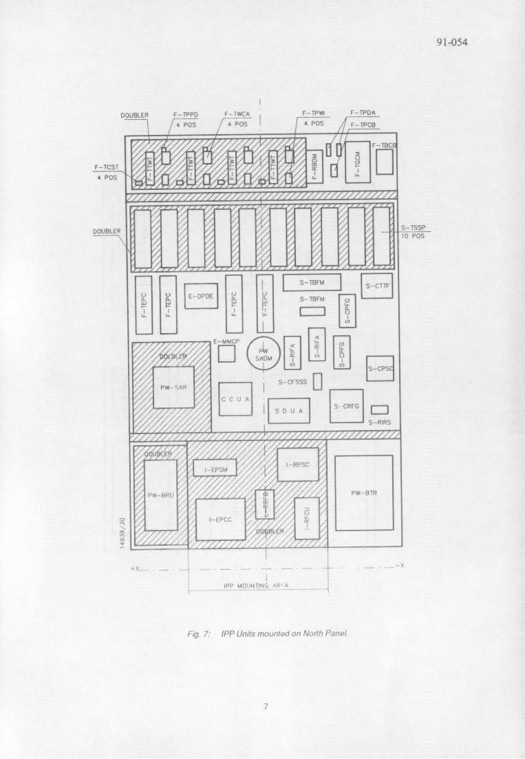
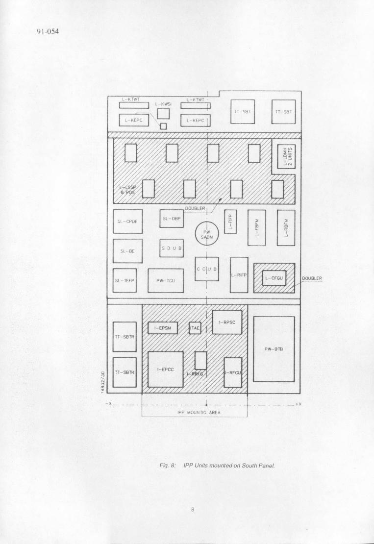
- These units as well as the power supply and control After RITA and EITA thruster tests in the vacuum facili-electronics (PSCU's and PCCE's) and the RIT RF- ties (University of Giessen and Culham Laboratory) thegenerators are mounted inside the heat radiating units are pre-integrated into the North and South IPPNorth and South panels (see Fig. 7 and 8). packages as depicted in Fig. 9 using dummy radiatorsThe control electronics unit of the two alignment panels for monitoring and cable routing (compare chaptermechanisms is located on the South panel. 3.2).
The North dummy panel carries on the inner side:- Cable connectors and pipe junctions lead through the The North dummy panel carries on the inner side:
radiator panels to the outside mounted alignment - PSCU, FCU, RFG of RITA;mechanisms (ITAM's) which carry one thruster pair - PCE, PSME of EITAeach.
on the outer side:
4. IPP/SPACECRAFT INTEGRATION SEQUENCE - ITAM with RIT and EIT thruster pair pre-assembled.
4.1 Overview The South dummy panel carrying on the inner side:
- PSCU, FCU, RFG of RITA;The IPP integration is carried out in three major steps: - PCCE, PSME of EITA;
- ITAE for both gimbal mechanisms.- Pre-integration of the assemblies;
on the outer side:- Integration of the PSDA together with the UPS and
main structure; - ITAM with RIT and EIT thruster pair pre-assembled.
6
91-054
DOUBLER F-TPPD F-TWCA F-TPWI F-TPDA
SPOS 4 POS I 4 POS F-TPCB
F-TBCE
F-TCST.
4 POS
DOUBLER S-TSSP
/ L K]E-MMCP < f ,
S-CFSSSPW-SAR U
CCA
SDUA S- CRFG
S-RIRS
/ I-RPSCiEPSM
SPIJ '/PW-BTR
o I-EPCC
IPP MCiNIINC, t, *
Fig. 7: IPP Units mounted on North Panel
7
91-054
S ] K , I /,
CCJB
c ci 8 //
L KP RFP
S /L ' " ,-~ / ,UBLER
s El PW ouc 0
E I-SBTH _ _C
/ /'///// / / '/
IPPF MCIUU lu AREA
Fiq. 8: IPP Units mounted on South Panel

91-054
IA- I
J-- .\
Fig. 9: Pre-Integrater, IPO with RITA FITA ITAM on llimmy North and South Panels.
After functional testing, the pre-integrated North/South Fill/vent Valves (HFVV, LFVV) on East panel;
packages are shipped for platform integration and electri- - All PSDA equipments on main platform (lowercal system testing to ALS/Roma together with all neces- side);sary ground support equipment. - Flow Control Unit/PSME inlet interface.
The PSDA equipment (functionally tested at unit level)will be integrated/tested together with the UPS in the inte-gration facility of UPS S/S responsible. 4. Mount propulsion platform from rear (-z) side into
Central Cylinder.
3 5. Purge Xe-lines, protect line ends and connect4.3 Subsystem and Spacecraft IntegrationHFVV and LFVV on +x (East) side.
The hadware dedicated to UPS S/S responsible for the 6. Perform electrical function check of all PSDA
propulsion subsystem integration consists of: equipments and harness using PSDA unit testequipments.
- Central Structure(Main/horiz Platform, Central Cylin-der, Shear webs, Propulsion Platform); 7. Perform PSDA leak/electrical function test usingPSDA unit test equipment.
- PSDA equipments (Xe tank, HPT, HFVV, LFVV, PSDA unt test equipment.
EPRE, EPRM, OXA, Filter, piping, manifolds, etc.). 8. Packing/shipping to ALS S/C integration facility.
The integration sequence for the IPP in described in b) Platform System Integration:the following (compare also with Figure's 5 to 9).
9. Remove pre-integ. RITA, EITA from dummy pan-
a) IPP Subsystem: els and transfer all equipment to theflight North andSouth panels.
1. Mount Xe-tank on the propulsion platform. 10. Connect all Xe-lines of FCU/PSME with lines on
2. Provide pipe junctions/brackets from Xe-tank to central structure,Connect allharnessofRITA/EITA
central cylinder, equipment with platform harness.
3. Mount all Xe-pipelines to brackets around central 11. Perform IPP leak/electrical function testing for final
cylinder with junctions to: acceptance (including alignment).
9

91-054
5.IPP SPECIFIC TESTS IN THE ARTEMIS PROGRAM 5.4 IPP Subsystem/System Tests
5.1 Thruster and Assembly Operational Tests In the development phase one engineering qual model(EQM) of the IPP will be integrated into the spacecraft
Since Ion thrusters can only be operated in a vacuum of EM for functional verification and compatibility testing.10 exp. -5 bar all thruster functional, performance, The flight IPP will be composed of:beam diagnostic, and lifecycle tests are performed indedicated vacuum facilities: - acceptance tested components (under flight environ-
mental conditions);- RITthrusterfunctionalperformance,beam diagnostic - functionally tested assemblies (RITA, EITA, ITAE);
and acceptance tests are performed at Giessen Uni- - pre-integrated IPP North and South packages onversity. dummy S/C radiator panels.
- RITA Lifetimetest with a dedicated development mod-el (flight type thruster, engineering model supply After integration/transfer into the flight spacecraft it willunits) are performed at ESTEC. The required 15.000 be functionally and environmental tested on Systemhours represent 1.5 times the thruster operating level.cycles for a 10 years mission.
- UK-10 thruster performance/acceptance test andEITA lifecycle test are all performed at CULHAM Lab- 6. CONCLUSIONSoratory. Requirements are the same as for RITA.
The ARTEMIS spacecraft design provides all physicalneeds for IPP accommodation.
5.2 PSDA Tests .The NSSK strategy together with the thruster alignmenton the S/C allows for a minimum number of redundant
Functional performance and flight acceptance tests are hardware (two pairs on North and South panels) resultingperformed at unit level, in an acceptable dry mass and power penalty for of theAfterdeliveryto integration facilities and relevant activi- S/C of 77 Kg resp. 180 W. The total propellant mass
ties performed functional, performance and leak tests are saving is 2 160 Kg.carried out at assembly level. Hereby the Xenon tank is The various mechanical, electrical and thermal func-loaded, the pressure regulator pressurized and function- tions fo the IPP equipment considerably influence theally tested and all valves and pipe connections leak design and lay-out of the spacecraft but can be matchedtested with the PSDA test equipment. Xe loading and without major problems if considered a priori.de-loading is performed by means of a special tankingequipment designed especially for this orogram.
7. REFERENCES5.3 ITAA Tests
/1 Palutan/Notarantonio
The main development test will be "ARTEMIS Mission Analysis Hanbook"(HBK/ART/0584/SES; 9-10-90)
- prequalification of ITA Electronics (EQM)/2 Tomasetto- assembly of an ITAM EOM with mass and thermal "IPP Requirement Specification
dummies for RIT and EIT thruster, but with flight type (SYS/ART/0029/SES; 31-10-90)piping, cables and thermal protection:
- thermal and functional testing of ITAA with the possi- /3 Bassnerbility of extension to life cycle testing (if required due "Ion Propulsion Package Design Description"to final operational analyses). (TDE/ART/0347/MBB)
The flight assembly will consist of en ironmental tested /4 Tomasetto, Silvicomponents and will be integrated irto the S/C as de- "Ion Propulsion Package S/S Specification"scribed sequentially in chapter 4 (SPE/ART/IPP-0700/ALS)
10