9150 portable furnace user's guide
TRANSCRIPT

9150 PortableFurnaceUser’s Guide
Rev. 872501
Hart Scientific

Rev. 872501
Fluke Corporation, Hart Scientific Division799 E. Utah Valley Drive • American Fork, UT 84003-9775 • USAPhone: +1.801.763.1600 • Telefax: +1.801.763.1010E-mail: [email protected]
www.hartscientific.comSubject to change without notice. • Copyright © 2005 • Printed in USA
Table of Contents
1 Before You Start . . . . . . . . . . . . . . . . . . . . . . . . . . 11.1 Symbols Used . . . . . . . . . . . . . . . . . . . . . . . . . . . . 1
1.2 Safety Information . . . . . . . . . . . . . . . . . . . . . . . . . . 21.2.1 WARNINGS . . . . . . . . . . . . . . . . . . . . . . . . . . . . . . . . . . . 21.2.2 CAUTIONS . . . . . . . . . . . . . . . . . . . . . . . . . . . . . . . . . . . 3
1.3 Authorized Service Centers. . . . . . . . . . . . . . . . . . . . . . 4
2 Introduction . . . . . . . . . . . . . . . . . . . . . . . . . . . . 7
3 Specifications and Environmental Conditions . . . . . . . . . . 93.1 Specifications . . . . . . . . . . . . . . . . . . . . . . . . . . . . . 9
3.2 Environmental Conditions . . . . . . . . . . . . . . . . . . . . . . 9
3.3 Warranty . . . . . . . . . . . . . . . . . . . . . . . . . . . . . . . 10
4 Safety Guidelines . . . . . . . . . . . . . . . . . . . . . . . . . 11
5 Quick Start . . . . . . . . . . . . . . . . . . . . . . . . . . . . 135.1 Unpacking . . . . . . . . . . . . . . . . . . . . . . . . . . . . . . 13
5.2 Set-Up . . . . . . . . . . . . . . . . . . . . . . . . . . . . . . . . 13
5.3 Power . . . . . . . . . . . . . . . . . . . . . . . . . . . . . . . . 13
5.4 Setting the Temperature . . . . . . . . . . . . . . . . . . . . . . . 14
6 Parts and Controls . . . . . . . . . . . . . . . . . . . . . . . . 156.1 Back Panel. . . . . . . . . . . . . . . . . . . . . . . . . . . . . . 15
6.2 Front Panel . . . . . . . . . . . . . . . . . . . . . . . . . . . . . 16
6.3 Constant Temperature Block Assembly . . . . . . . . . . . . . . . 176.3.1 Constant Temperature Block . . . . . . . . . . . . . . . . . . . . . . . . . . 176.3.2 Probe Sleeves and Tongs . . . . . . . . . . . . . . . . . . . . . . . . . . . . 17
7 General Operation . . . . . . . . . . . . . . . . . . . . . . . . 197.1 Changing Display Units . . . . . . . . . . . . . . . . . . . . . . . 19
7.2 Switching to 230V Operation . . . . . . . . . . . . . . . . . . . . 19
8 Controller Operation . . . . . . . . . . . . . . . . . . . . . . . 218.1 Well Temperature . . . . . . . . . . . . . . . . . . . . . . . . . . 21
8.2 Temperature Set-point . . . . . . . . . . . . . . . . . . . . . . . . 21
i

8.2.1 Programmable Set-points . . . . . . . . . . . . . . . . . . . . . . . . . . . . 218.2.2 Set-point Value . . . . . . . . . . . . . . . . . . . . . . . . . . . . . . . . . 238.2.3 Temperature Scale Units . . . . . . . . . . . . . . . . . . . . . . . . . . . . 23
8.3 Scan . . . . . . . . . . . . . . . . . . . . . . . . . . . . . . . . . 248.3.1 Scan Control . . . . . . . . . . . . . . . . . . . . . . . . . . . . . . . . . . 248.3.2 Scan Rate . . . . . . . . . . . . . . . . . . . . . . . . . . . . . . . . . . . . 24
8.4 Ramp and Soak Program . . . . . . . . . . . . . . . . . . . . . . 258.4.1 Program Points . . . . . . . . . . . . . . . . . . . . . . . . . . . . . . . . . 258.4.2 Number of Program Points . . . . . . . . . . . . . . . . . . . . . . . . . . . 258.4.3 Program Set-Points . . . . . . . . . . . . . . . . . . . . . . . . . . . . . . . 268.4.4 Program Function Mode . . . . . . . . . . . . . . . . . . . . . . . . . . . . 278.4.5 Program Control . . . . . . . . . . . . . . . . . . . . . . . . . . . . . . . . 28
8.5 Secondary Menu. . . . . . . . . . . . . . . . . . . . . . . . . . . 28
8.6 Heater Power . . . . . . . . . . . . . . . . . . . . . . . . . . . . 28
8.7 Set-point Voltage . . . . . . . . . . . . . . . . . . . . . . . . . . 29
8.8 Proportional Band . . . . . . . . . . . . . . . . . . . . . . . . . . 29
8.9 Controller Configuration . . . . . . . . . . . . . . . . . . . . . . 30
8.10 Operating Parameters . . . . . . . . . . . . . . . . . . . . . . . . 318.10.1 High Limit. . . . . . . . . . . . . . . . . . . . . . . . . . . . . . . . . . . . 318.10.2 Soft Cutout . . . . . . . . . . . . . . . . . . . . . . . . . . . . . . . . . . . 318.10.3 Cutout Reset Mode . . . . . . . . . . . . . . . . . . . . . . . . . . . . . . . 32
8.11 Serial Interface Parameters . . . . . . . . . . . . . . . . . . . . . 328.11.1 BAUD Rate . . . . . . . . . . . . . . . . . . . . . . . . . . . . . . . . . . . 338.11.2 Sample Period. . . . . . . . . . . . . . . . . . . . . . . . . . . . . . . . . . 338.11.3 Duplex Mode . . . . . . . . . . . . . . . . . . . . . . . . . . . . . . . . . . 338.11.4 Linefeed . . . . . . . . . . . . . . . . . . . . . . . . . . . . . . . . . . . . . 34
8.12 Calibration Parameters . . . . . . . . . . . . . . . . . . . . . . . 348.12.1 Hard Cutout . . . . . . . . . . . . . . . . . . . . . . . . . . . . . . . . . . . 358.12.2 CT1, CT2, and CT3 . . . . . . . . . . . . . . . . . . . . . . . . . . . . . . . 358.12.3 CE1, CE2, and CE3 . . . . . . . . . . . . . . . . . . . . . . . . . . . . . . . 35
9 Digital Communication Interface . . . . . . . . . . . . . . . . 379.1 Serial Communications . . . . . . . . . . . . . . . . . . . . . . . 37
9.1.1 Wiring . . . . . . . . . . . . . . . . . . . . . . . . . . . . . . . . . . . . . . 379.1.2 Setup . . . . . . . . . . . . . . . . . . . . . . . . . . . . . . . . . . . . . . 37
9.1.2.1 BAUD Rate . . . . . . . . . . . . . . . . . . . . . . . . . . . . . . . . . . . . . . . 389.1.2.2 Sample Period. . . . . . . . . . . . . . . . . . . . . . . . . . . . . . . . . . . . . . 389.1.2.3 Duplex Mode . . . . . . . . . . . . . . . . . . . . . . . . . . . . . . . . . . . . . . 389.1.2.4 Linefeed . . . . . . . . . . . . . . . . . . . . . . . . . . . . . . . . . . . . . . . . . 38
9.1.3 Serial Operation . . . . . . . . . . . . . . . . . . . . . . . . . . . . . . . . . 38
9.2 Interface Commands . . . . . . . . . . . . . . . . . . . . . . . . 39
10 Test Probe Calibration . . . . . . . . . . . . . . . . . . . . . . 4310.1 Calibrating a Single Probe. . . . . . . . . . . . . . . . . . . . . . 43
10.2 Furnace Characteristics . . . . . . . . . . . . . . . . . . . . . . . 43
ii
10.2.1 Stabilization and Accuracy . . . . . . . . . . . . . . . . . . . . . . . . . . . 43
11 Calibration Procedure . . . . . . . . . . . . . . . . . . . . . . 4511.1 Calibration Points . . . . . . . . . . . . . . . . . . . . . . . . . . 45
11.2 Calibration Procedure . . . . . . . . . . . . . . . . . . . . . . . . 45
12 Maintenance . . . . . . . . . . . . . . . . . . . . . . . . . . . 47
13 Troubleshooting. . . . . . . . . . . . . . . . . . . . . . . . . . 4913.1 Troubleshooting Problems, Possible Causes, and Solutions . . . . 49
13.2 Comments . . . . . . . . . . . . . . . . . . . . . . . . . . . . . . 5013.2.1 EMC Directive . . . . . . . . . . . . . . . . . . . . . . . . . . . . . . . . . 5013.2.2 Low Voltage Directive (Safety) . . . . . . . . . . . . . . . . . . . . . . . . . 50
iii

1 Before You Start
1.1 Symbols UsedTable 1 lists the International Electrical Symbols. Some or all of these symbolsmay be used on the instrument or in this manual.
Symbol Description
AC (Alternating Current)
AC-DC
Battery
CE Complies with European Union Directives
DC
Double Insulated
Electric Shock
Fuse
PE Ground
Hot Surface (Burn Hazard)
Read the User’s Manual (Important Information)
Off
On
1
1 Before You StartSymbols Used
Table 1 International Electrical Symbols

Symbol Description
Canadian Standards Association
OVERVOLTAGE (Installation) CATEGORY II, Pollution Degree 2 per IEC1010-1 re-fers to the level of Impulse Withstand Voltage protection provided. Equipment ofOVERVOLTAGE CATEGORY II is energy-consuming equipment to be supplied fromthe fixed installation. Examples include household, office, and laboratory appliances.
C-TIC Australian EMC Mark
The European Waste Electrical and Electronic Equipment (WEEE) Directive(2002/96/EC) mark.
1.2 Safety InformationUse this instrument only as specified in this manual. Otherwise, the protectionprovided by the instrument may be impaired.
The following definitions apply to the terms “Warning” and “Caution”.
• “Warning” identifies conditions and actions that may pose hazards to theuser.
• “Caution” identifies conditions and actions that may damage the instru-ment being used.
1.2.1 WARNINGSTo avoid personal injury, follow these guidelines.
BURN HAZARD - DO NOT touch the well access surface of the unit.
The temperature of the well access is the same as the actual temperature shownon the display. If the unit is set at 600°C and the display reads 600°C, the wellis at 600°C.
The top sheet metal of the furnace may exhibit extreme temperatures for areasclose to the well access.
The air over the well can reach temperatures greater than 200°C. Probes shouldonly be inserted and removed from the unit when the unit is set at temperaturesless than 200°C.
DO NOT turn off the unit at temperatures higher than 100°C. This could createa hazardous situation. Select a set-point less than 100°C and allow the unit tocool before turning it off.
DO NOT remove inserts and insulators at high temperatures. Inserts and insu-lators are the same temperature as the display temperature.
9150 Portable Furnace
User’s Guide
2

DO NOT operate this unit without a properly grounded, properly polarizedpower cord.
DO NOT connect this unit to a non-grounded, non-polarized outlet.
HIGH VOLTAGE is used in the operation of this equipment. SEVERE IN-JURY OR DEATH may result if personnel fail to observe safety precautions.Before working inside the equipment, turn the power off and disconnect thepower cord.
Always replace the fuse with one of the same rating, voltage, and type.
Overhead clearance is required. DO NOT place this instrument under a cabinetor other structure.
DO NOT use this unit for any application other than calibration work.
DO NOT use this unit in environments other than those listed in the user’sguide.
DO NOT turn the unit upside down with the inserts in place; the inserts willfall out of the unit.
DO NOT operate near flammable materials.
Use of this instrument at HIGH TEMPERATURES for extended periods oftime requires caution.
Completely unattended high temperature operation is not recommended forsafety reasons.
Before initial use, after transport, and anytime the furnace has not been ener-gized for more than 10 days, the calibrator must be energized for a dry-out pe-riod of 1 to 2 hours before it can be assumed to meet all of the safetyrequirements of the IEC1010-1.
Materials used in this furnace may be irritating to skin, eyes, and respiratorytract. Consult the material manufacturer’s MSDS (Material Safety Data Sheet).Proper ventilation and safety precautions must be observed.
Follow all safety guidelines listed in the user’s guide.
Calibration Equipment should only be used by Trained Personnel.
1.2.2 CAUTIONSTo avoid possible damage to the instrument, follow these guidelines.
DO NOT plug the unit into 230 V if the heater switches and fuse holder read115 V. This action will cause the fuses to blow and may damage the instrument.
Components and heater lifetime can be shortened by continuous high tempera-ture operation.
Most probes have handle temperature limits. Be sure that the probe hand tem-perature limit is not exceeded in the air above the unit.
3
1 Before You StartSafety Information
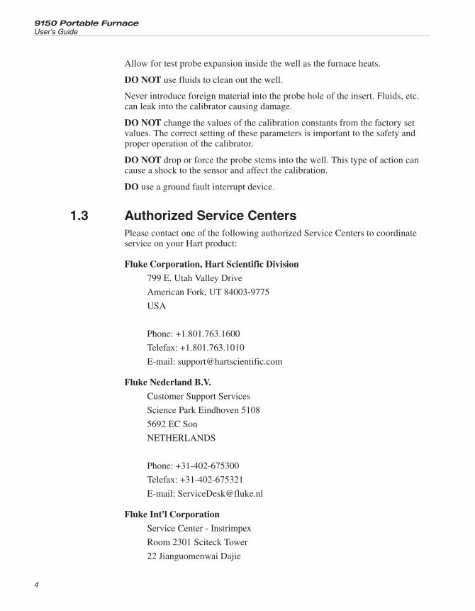
Allow for test probe expansion inside the well as the furnace heats.
DO NOT use fluids to clean out the well.
Never introduce foreign material into the probe hole of the insert. Fluids, etc.can leak into the calibrator causing damage.
DO NOT change the values of the calibration constants from the factory setvalues. The correct setting of these parameters is important to the safety andproper operation of the calibrator.
DO NOT drop or force the probe stems into the well. This type of action cancause a shock to the sensor and affect the calibration.
DO use a ground fault interrupt device.
1.3 Authorized Service CentersPlease contact one of the following authorized Service Centers to coordinateservice on your Hart product:
Fluke Corporation, Hart Scientific Division
799 E. Utah Valley Drive
American Fork, UT 84003-9775
USA
Phone: +1.801.763.1600
Telefax: +1.801.763.1010
E-mail: [email protected]
Fluke Nederland B.V.
Customer Support Services
Science Park Eindhoven 5108
5692 EC Son
NETHERLANDS
Phone: +31-402-675300
Telefax: +31-402-675321
E-mail: [email protected]
Fluke Int'l Corporation
Service Center - Instrimpex
Room 2301 Sciteck Tower
22 Jianguomenwai Dajie
9150 Portable Furnace
User’s Guide
4
Chao Yang District
Beijing 100004, PRC
CHINA
Phone: +86-10-6-512-3436
Telefax: +86-10-6-512-3437
E-mail: [email protected]
Fluke South East Asia Pte Ltd.
Fluke ASEAN Regional Office
Service Center
60 Alexandra Terrace #03-16
The Comtech (Lobby D)
118502
SINGAPORE
Phone: +65 6799-5588
Telefax: +65 6799-5588
E-mail: [email protected]
When contacting these Service Centers for support, please have the followinginformation available:
• Model Number
• Serial Number
• Voltage
• Complete description of the problem
5
1 Before You StartAuthorized Service Centers

2 Introduction
The Hart Scientific 9150 thermocouple furnace can be used for calibrating ther-mocouple and RTD temperature probes. Calibrations may be done over a rangeof 150°C to 1200°C (302°F to 2192°F). Temperature display of the 9150 is 0.1degrees below 1000°and 1 degrees above 1000°.
The furnace features:
• Rapid heating and cooling
• Interchangeable multiple hole probe sleeves
• Convenient handle
• RS-232 interface
Built in programmable features include:
• Temperature scan rate control
• Eight set-point memory
• Adjustable readout in °C or °F
The temperature is accurately controlled by Hart’s hybrid analog/digital con-troller. The controller uses a Type S thermocouple as a sensor and controls thewell temperature with a solid state relay (triac) driven heater. The furnaceshould be calibrated yearly by trained personnel at Hart Scientific.
The LED front panel continuously shows the current well temperature. Thetemperature may be easily set with the control buttons to any desired tempera-ture within the specified range. The calibrator’s multiple fault protection de-vices insure user and instrument safety and protection.
The 9150 calibrator furnace was designed for portability, low cost, and ease ofoperation. Through proper use, the instrument will provide continued accuratecalibration of temperature sensors and devices. The user should be familiarwith the safety guidelines and operating procedures of the furnace as describedin this manual.
7
2 Introduction

3 Specifications and EnvironmentalConditions
3.1 Specifications
Temperature Range 150–1200°C (302–2192°F)
Display Resolution 0.1° to 999.9°, 1° above 1000°
Stability ±0.5°C
Display Accuracy ±5.0°C
Well Diameter 1.25" (32 mm)
Well Depth 4" (102 mm)
Heating Time 35 minutes to 1200°C
Cooling Time 140 minutes with block
Well to Well Uniformity ±2.5°C (insert “C” at 1200°C)
Stabilization 20 minutes
Power 115 VAC (±10%), 10.5 amps [230 VAC (±10%), 5.2 amps] switchable,50/60 Hz, 1200 W
Size 12.4" H x 8.2" W x 12.4"D (315 x 208 x 315 mm)
Weight 28 lb. (13 kg)
Fault Protection Sensor burnout and short protection, over temperature thermal cutout
3.2 Environmental ConditionsAlthough the instrument has been designed for optimum durability and trou-ble-free operation, it must be handled with care. The instrument should not beoperated in an excessively dusty or dirty environment. Maintenance and clean-ing recommendations can be found in the Maintenance Section of this manual.
The instrument operates safely under the following conditions:
• temperature range: 5 - 50°C (41 - 122°F)
• ambient relative humidity: 15 - 50%
• pressure: 75kPa - 106kPa
• mains voltage within ± 10% of nominal
• vibrations in the calibration environment should be minimized
• altitude less than 2000 meters
9
3 Specifications and Environmental ConditionsSpecifications

3.3 WarrantyFluke Corporation, Hart Scientific Division (Hart) warrants this product to befree from defects in material and workmanship under normal use and servicefor a period as stated in our current product catalog from the date of shipment.This warranty extends only to the original purchaser and shall not apply to anyproduct which, in Hart's sole opinion, has been subject to misuse, alteration,abuse or abnormal conditions of operation or handling.
Software is warranted to operate in accordance with its programmed instruc-tions on appropriate Hart products. It is not warranted to be error free.
Hart's obligation under this warranty is limited to repair or replacement of aproduct which is returned to Hart within the warranty period and is determined,upon examination by Hart, to be defective. If Hart determines that the defect ormalfunction has been caused by misuse, alteration, abuse or abnormal condi-tions or operation or handling, Hart will repair the product and bill the pur-chaser for the reasonable cost of repair.
To exercise this warranty, the purchaser must forward the product after callingor writing an Authorized Service Center (see Section 1.3). The service centersassume NO risk for in-transit damage.
THE FOREGOING WARRANTY IS PURCHASER'S SOLE AND EXCLU-SIVE REMEDY AND IS IN LIEU OF ALL OTHER WARRANTIES, EX-PRESS OR IMPLIED, INCLUDING BUT NOT LIMITED TO ANYIMPLIED WARRANTY OR MERCHANTABILITY, OR FITNESS FOR ANYPARTICULAR PURPOSE OR USE. HART SHALL NOT BE LIABLE FORANY SPECIAL, INDIRECT, INCIDENTAL, OR CONSEQUENTIAL DAM-AGES OR LOSS WHETHER IN CONTRACT, TORT, OR OTHERWISE.
9150 Portable Furnace
User’s Guide
10

4 Safety Guidelines
• Operate the instrument in room temperatures between 5-50°C (41-122°F).Allow sufficient air circulation by leaving at least 6 inches of space be-tween the instrument and nearby objects. Overhead clearance needs to al-low for safe and easy insertion and removal of probes for calibration.
• The furnace is a precision instrument. Although it has been designed foroptimum durability and trouble free operation, it must be handled withcare. Always carry the unit in an upright position to prevent the probesleeves from dropping out. The convenient fold-up handle allows onehand carrying. The instrument should not be operated in excessively wet,oily, dusty, or dirty environments. It is important to keep the well of theinstrument clean and clear of any foreign matter. Do not operate nearflammable materials.
• DO NOT use fluids to clean out the well.
• The instrument can generate extreme temperatures. Precautions must betaken to prevent personal injury or damage to objects. Probes may be ex-tremely hot or cold when removed from the instrument. Cautiously handleprobes to prevent personal injury. Always use the special sleeve tongs thatare supplied with the calibrator to remove the sleeve. Carefully placeprobes on a heat/cold resistant surface or rack until they are at room tem-perature. Never place any objects other than the special probe sleeves sup-plied with the calibrator into the well.
• Use only a grounded AC mains supply of the appropriate voltage topower the instrument. Refer to Section 3.1, Specifications, for power de-tails.
• Before initial use, after transport, and anytime the furnace has not beenenergized for more than 10 days, the instrument needs to be energized fora “dry-out” period of 1-2 hours before it can be assumed to meet all of thesafety requirements of the IEC 1010-1.
• The instrument is equipped with operator accessible fuses. If a fuseblows, it may be due to a power surge or failure of a component. Replacethe fuse once. If the fuse blows a second time, it is likely caused by fail-ure of a component part. If this occurs, contact Hart Scientific CustomerService. Always replace the fuse with one of the same rating, voltage, andtype. Never replace the fuse with one of a higher current rating.
• If a mains supply power fluctuation occurs, immediately turn off the in-strument. Power bumps from brownouts and blackouts could damage theinstrument. Wait until the power has stabilized before re-energizing theinstrument.
• Air circulated through the unit keeps the chassis cool. DO NOT SHUTOFF THE FURNACE WHILE AT HIGH TEMPERATURES.
11
4 Safety Guidelines

5 Quick Start
5.1 UnpackingUnpack the furnace carefully and inspect it for any damage that may have oc-curred during shipment. If there is shipping damage, notify the carrierimmediately.
Verify that the following components are present:
• 9150 Furnace
• 3150, Insert
• Insert Insulator
• Power Cord
• Manual
• RS-232 Cable
5.2 Set-UpPlace the calibrator on a flat surface with at least 6 inches of free space aroundthe instrument. Plug the power cord into a grounded mains outlet. Observe thatthe nominal voltage corresponds to that indicated on the back of the calibrator.
Carefully insert the probe sleeve into the well. (DO NOT drop the sleeve in thewell.) Probe sleeve holes should be of the smallest diameter possible while stillallowing the probe to slide in and out easily. Sleeves with various hole sizes areavailable from Hart Scientific. The well must be clear of any foreign objects,dirt and grit before the sleeve is inserted. The sleeve is inserted with the twosmall tong holes positioned upward.
Turn on the power to the calibrator by toggling the switch on the power entrymodule. The fan should begin quietly blowing air through the instrument andthe controller display should illuminate after 3 seconds. After a brief self testthe controller should begin normal operation. If the unit fails to operate pleasecheck the power connection.
The display begins to show the well temperature and the well heater starts oper-ating to bring the temperature of the well to the set-point temperature.
5.3 PowerPlug the furnace power cord into a mains outlet of the proper voltage, fre-quency, and current capability. Refer to Section 3.1, Specifications, for powerdetails. Turn the furnace on using the rear panel “POWER” switch. The furnaceturns on and begins to heat to the previously programmed temperatureset-point. The front panel LED display indicates the actual furnace temperature.
13
5 Quick StartUnpacking

5.4 Setting the TemperatureSection 8 explains in detail how to set the temperature set-point on the calibra-tor using the front panel keys. The procedure is summarized here.
(1) Press “SET” twice to access the set-point value.
(2) Press “SET” to move the cursor to the units that need changing.
(3) Press “UP” or “DOWN” to change the set-point value.
(4) Press “SET” until the display exits to store the new set-point.
(5) Press “EXIT” to return to the temperature display without saving thenew set-point value.
When the set-point temperature is changed the controller switches the wellheater on or off to raise or lower the temperature. The displayed well tempera-ture gradually changes until it reaches the set-point temperature. The well mayrequire 35 minutes to reach the set-point depending on the span. Another 10 to20 minutes is required to stabilize within ±0.5°C of the set-point. Ultimate sta-bility may take 15 to 20 minutes more of stabilization time.
9150 Portable Furnace
User’s Guide
14

6 Parts and Controls
The user should become familiar with the furnace back panel, front panel, andconstant temperature block assembly.
6.1 Back PanelThe back panel (Figure 1) features the Power Entry Module (PEM) that con-tains the power cord socket, the power switch, and the heater voltage switch,the serial port, and the fan.
Power Cord - On the back of the calibrator is the removable power cord inletthat plugs into an IEC grounded socket.
Power Switch - The power switch is located on the power entry module(PEM). The PEM also houses the fuses and the dual voltage selector. The PEMand Heater Voltage Switch allow the unit to be field switchable for 115 VAC(±10%) or 230 VAC (±10%) operation.
Heater Voltage Switch - To be used only when changing the input voltage.(See Section 7.2 for instructions.)
Serial Port - A DB-9 male connector is present for interfacing the calibrator toa computer or terminal with serial RS-232 communications.
15
6 Parts and ControlsBack Panel
Figure 1 Back Panel

Fan - The fan inside the calibrator runs continuously when the unit is being op-erated to provide cooling for the instrument. Slots at the top and sides of thecalibrator are provided for airflow. The area around the calibrator must be keptclear to allow adequate ventilation. The airflow is directed upward and can beextremely hot.
6.2 Front PanelThe front panel consists of the controller display and the controller keypad asshown in Figure 2.
Controller Display - The digital display is an important part of the temperaturecontroller because it not only displays set and actual temperatures but also dis-plays various calibrator functions, settings, and constants. The display showstemperatures in units according to the selected scale °C or °F.
Controller Keypad - The four button keypad allows easy setting of theset-point temperature. The control buttons (SET, DOWN, UP, and EXIT) areused to set the calibrator temperature set-point, access and set other operatingparameters, and access and set calibration parameters.
Setting the control temperature is done directly in degrees of the current scale.It can be set to one-tenth of a degree Celsius or Fahrenheit.
The functions of the buttons are as follows:
SET – Used to display the next parameter in the menu and to store parametersto the displayed value.
DOWN – Used to decrement the displayed value of parameters.
UP – Used to increment the displayed value.
9150 Portable Furnace
User’s Guide
16
Figure 2 Front Panel

EXIT – Used to exit from a menu. When EXIT is pressed any changes made tothe displayed value are ignored.
6.3 Constant Temperature Block AssemblyThe constant temperature block assembly is shown in Figure 3 and consists ofremovable inserts.
6.3.1 Constant Temperature BlockThe “Block” is made of aluminum-oxide and provides a relatively constant andaccurate temperature environment for the sensor that is to be calibrated. A1.25-inch diameter well is provided that may be used for sensors of that size ormay be sleeved down with various sized multi-hole probe sleeves. Heaters sur-round the block assembly and provide even heat to the sensor. A Type S ther-mocouple is used to sense and control the temperature of the block. The entireassembly is surrounded by a heat reflector to thermally isolate the chassis andelectronics.
6.3.2 Probe Sleeves and TongsThe calibrator is supplied with a multi-hole aluminum-oxide probe sleeve andinsulator sleeve for insertion into the calibrator well and tongs for removingsleeves. Probe sleeves of various hole sizes are available to allow the user’sprobe to fit snugly into the well whatever the diameter of the probe.
Insert A and an insulator is provided unless otherwise indicated . The insertsare:
17
6 Parts and ControlsConstant Temperature Block Assembly
Figure 3 Removable Inserts

• Insert A Model 3150-2 (variety block): 1/2”, 1/4”, 3/8”, 3/16”, 1/8”, and1/16” holes
• Insert B Model 3150-3 (comparison block): two each 3/8”, 1/4”, and3/16” holes
or
• Insert C Model 3150-4 (1/4” comparison block): six 1/4” holes
9150 Portable Furnace
User’s Guide
18

7 General Operation
7.1 Changing Display UnitsThe 9150 can display temperature in Celsius or Fahrenheit. The temperatureunits are shipped from the factory set to Celsius. To change to Fahrenheit orback to Celsius there are two ways:
1 - Press the “SET” and “DOWN” simultaneously.
or
1 - Press the “SET” key three times from the temperature display and then“EXIT” to show the units.
Un= C
2 - Press the “UP” or “DOWN” key to change units.
3 - Press “SET” to store changes and then “EXIT” to display the temperature.
7.2 Switching to 230V OperationThe 9150 is switchable from 115 VAC to 230 VAC 50/60 Hz. Switching thevoltage can change the calibration, so the unit should be calibrated afterchanging the input voltage.
To change from 115 VAC to 230 VAC
1. Unplug the unit.
2. With a small straight slot screwdriver remove the fuse holder from thePEM located on the back of the unit.
3. Replace the two 12A F 250V fuses with two 6.3A F 250V fuses.
4. Replace the fuse holder with the “230V” in the display window.
5. Lay the unit on its side and with a small straight slot screwdriver, movethe heater switches located on the bottom of the unit to display “230V”.
Note: If the heater switches and the fuse holder do not all read “230V whencomplete, the unit will either not heat or only heat at a fraction of its capacity.If not done properly, the unit could become damaged and void the calibrationand warranty. Refer to Section 3.1, Specifications, for correct fuse usage.
CAUTION: Do not plug the unit into 230V if the heater switches and fuseholder read 115V. This will cause the fuses to blow and may damage theinstrument.
19
7 General OperationChanging Display Units

8 Controller Operation
This section discusses in detail how to operate the furnace temperature control-ler using the front control panel. By using the front panel key-switches andLED display the user may monitor the well temperature, adjust the set-pointtemperature in degrees C or F, monitor the heater output power, adjust the con-troller proportional band, and program the probe calibration parameters, operat-ing parameters, serial interface configuration, and controller calibrationparameters. Operation of the functions and parameters are shown in theflowchart in Figure 4 on page 22. This chart may be copied for reference.
In the following discussion a button with the word SET, UP, DOWN, or EXITinside indicates the panel button while the dotted box indicates the displayreading. Explanation of the button or display reading are to the right of eachbutton or display value.
8.1 Well TemperatureThe digital LED display on the front panel allows direct viewing of the actualwell temperature. This temperature value is what is normally shown on the dis-play. The units, C or F, of the temperature value are displayed at the right. Forexample,
962.3 C Well temperature in degrees Celsius
The temperature displayed function may be accessed from any other functionby pressing the “EXIT” button.
8.2 Temperature Set-pointThe temperature set-point can be set to any value within the range and resolu-tion as given in the specifications. Be careful not to exceed the safe upper tem-perature limit of any device inserted into the well.
Setting the temperature involves two steps: (1) select the set-point memory and(2) adjust the set-point value.
8.2.1 Programmable Set-pointsThe controller stores 8 set-point temperatures in memory. The set-points can bequickly recalled to conveniently set the calibrator to a previously programmedtemperature set-point.
To set the temperature one must first select the set-point memory. This functionis accessed from the temperature display function by pressing “SET”. Thenumber of the set-point memory currently being used is shown at the left on thedisplay followed by the current set-point value.
21
8 Controller OperationWell Temperature

9150 Portable Furnace
User’s Guide
22
Figure 4 Controller Operation Flowchart

200.0 C Well temperature in degrees Celsius
S Access set-point memory
1. 200. Set-point memory 1, 200.0°C currently used
To change the set-point memory press “UP” or “DOWN”.
5. 900. New set-point memory 5, 900.0°C
Press “SET” to accept the new selection and access the set-point value.
S Accept selected set-point memory
8.2.2 Set-point ValueThe set-point value may be adjusted after selecting the set-point memory andpressing “SET”.
0900.0 Set-point value in °C
The first digit flashes on and off. If the set-point value is correct, press “EXIT”to display the temperature scale units.
If the first digit is correct press “SET”.
To adjust the first digit, press “UP” or “DOWN”. Then, press “SET” to go tothe second digit. The second digit of the temperature should now be flashing.Adjust this digit by pressing “UP” or “DOWN”.
Press “SET” to accept the second digit and repeat until the last digit has beenadjusted.
0962.7 New set-point value
Press “SET” to accept the new set-point. If “EXIT” is pressed all changes madeto the set-point are discarded.
S Accept new set-point value
8.2.3 Temperature Scale UnitsTemperature Scale Units of the controller are set by the user to degrees Celsius(°C) or Fahrenheit (°F). The units are used in displaying the well temperature,set-point, and proportional band.
Press “SET” after adjusting the set-point value to change display units.
Un= C
23
8 Controller OperationTemperature Set-point

Scale units currently selected
Press “UP” or “DOWN” to change the units.
Un= F New units selected
Press “EXIT” to display the well temperature or press “SET” to access the scancontrol.
8.3 ScanThe scan rate can be set and enabled so that when the set-point is changed thefurnace heats or cools at a specified rate (degrees per minute) until it reachesthe new set-point. With the scan disabled the furnace heats or cools at the maxi-mum possible rate.
8.3.1 Scan ControlThe scan is controlled with the scan on/off function that appears in the mainmenu after the temperature scale units.
Sc=OFF Scan function off
Press “UP” or “DOWN” to toggle the scan on or off.
Sc=On Scan function on
Press “SET” to accept the present setting and access the scan rate.
S Accept scan setting
8.3.2 Scan RateThe next function in the main menu is the scan rate. The scan rate can be setfrom .1 to 99.9°C/minute. The maximum scan rate however is actually limitedby the natural heating or cooling rate of the instrument. This rate is often lessthan 100°C/minute, especially when cooling.
The scan rate function appears in the main menu after the scan control function.The scan rate units are in degrees per minute, degrees C or F depending on theselected units.
Sr=10.0 Scan rate in °C/min.
Press “UP” or “DOWN” to change the scan rate.
Sr= 5.8 New scan rate
9150 Portable Furnace
User’s Guide
24
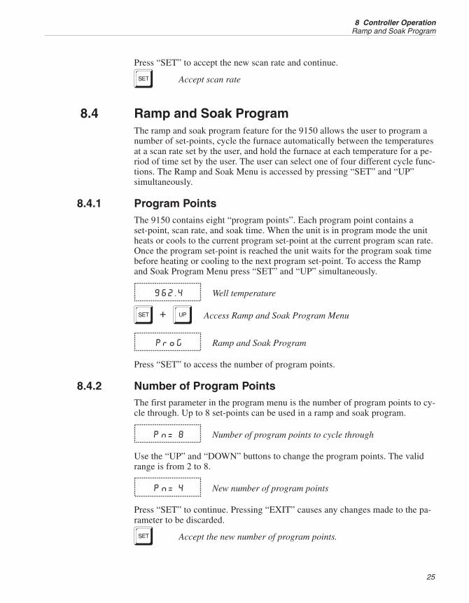
Press “SET” to accept the new scan rate and continue.
S Accept scan rate
8.4 Ramp and Soak ProgramThe ramp and soak program feature for the 9150 allows the user to program anumber of set-points, cycle the furnace automatically between the temperaturesat a scan rate set by the user, and hold the furnace at each temperature for a pe-riod of time set by the user. The user can select one of four different cycle func-tions. The Ramp and Soak Menu is accessed by pressing “SET” and “UP”simultaneously.
8.4.1 Program PointsThe 9150 contains eight “program points”. Each program point contains aset-point, scan rate, and soak time. When the unit is in program mode the unitheats or cools to the current program set-point at the current program scan rate.Once the program set-point is reached the unit waits for the program soak timebefore heating or cooling to the next program set-point. To access the Rampand Soak Program Menu press “SET” and “UP” simultaneously.
962.4 Well temperature
S+U Access Ramp and Soak Program Menu
ProG Ramp and Soak Program
Press “SET” to access the number of program points.
8.4.2 Number of Program PointsThe first parameter in the program menu is the number of program points to cy-cle through. Up to 8 set-points can be used in a ramp and soak program.
Pn= 8 Number of program points to cycle through
Use the “UP” and “DOWN” buttons to change the program points. The validrange is from 2 to 8.
Pn= 4 New number of program points
Press “SET” to continue. Pressing “EXIT” causes any changes made to the pa-rameter to be discarded.
S Accept the new number of program points.
25
8 Controller OperationRamp and Soak Program

8.4.3 Program Set-PointsThe controller allows the user to adjust up to eight program points. These areaccessed by pressing “SET” after setting the number of program points as de-scribed in Section 8.4.2. Each program point has three associated parameters:the program set-point, the program scan rate, and the program hold (or soak)time. After adjusting the number of program points press “SET”.
SP 1 Program point 1
Use the “UP” or “DOWN” buttons to select any of the program points. Thecontroller only allows the user to edit program points that are less than or equalto the number of programs points selected as explained in Section 8.4.2. Forexample, if the user has selected 4 program points program points 5, 6, 7, and 8cannot be edited.
SP 4 Program point 4
Press “SET” to edit a program point.
S Edit program point
The first value to edit is the program set-point.
0962.7 Program set-point value in °C
Use “UP”, “DOWN”, and “SET” to adjust the set-point as each digit flashes.
0970.0 New program set-point value for program point 4
Press “SET” to save the new set-point value or “EXIT” to discard changes.
S Accept the program point set-point
The next value to edit is the program soak time.
Pt 4 Program point 4 soak time
Press “SET” to edit the program soak time.
S Edit program point soak time
00001 Current program point soak time
Use “UP”, “DOWN”, and “SET” to adjust the program soak time. This valuecan be any integer from 0 to 14400. This time is the minutes the programset-point maintains after the temperature of the furnace has settled and beforeproceeding to the next set-point. Each digit flashes individually to indicate that
9150 Portable Furnace
User’s Guide
26
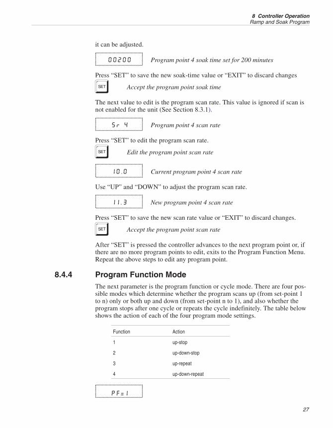
it can be adjusted.
00200 Program point 4 soak time set for 200 minutes
Press “SET” to save the new soak-time value or “EXIT” to discard changes
S Accept the program point soak time
The next value to edit is the program scan rate. This value is ignored if scan isnot enabled for the unit (See Section 8.3.1).
Sr 4 Program point 4 scan rate
Press “SET” to edit the program scan rate.
S Edit the program point scan rate
10.0 Current program point 4 scan rate
Use “UP” and “DOWN” to adjust the program scan rate.
11.3 New program point 4 scan rate
Press “SET” to save the new scan rate value or “EXIT” to discard changes.
S Accept the program point scan rate
After “SET” is pressed the controller advances to the next program point or, ifthere are no more program points to edit, exits to the Program Function Menu.Repeat the above steps to edit any program point.
8.4.4 Program Function ModeThe next parameter is the program function or cycle mode. There are four pos-sible modes which determine whether the program scans up (from set-point 1to n) only or both up and down (from set-point n to 1), and also whether theprogram stops after one cycle or repeats the cycle indefinitely. The table belowshows the action of each of the four program mode settings.
Function Action
1 up-stop
2 up-down-stop
3 up-repeat
4 up-down-repeat
Pf=1
27
8 Controller OperationRamp and Soak Program

Program mode
Press “SET” to adjust the program mode and the “UP” or “DOWN” buttons tochange the mode.
Pf=4 New mode
Press “SET” to continue or “EXIT” to continue without saving the new value.
S Save new setting
8.4.5 Program ControlThe final parameter in the program menu is the control parameter. You maychoose between three options to either start the program from the beginning,continue the program from where it was when it was stopped, or stop theprogram.
P=OFF Program presently off
Use the “UP” or “DOWN” buttons to change the status.
P=Go Start cycle from beginning
Press “SET” to activate the new program control command and return to thetemperature display.
S Activate new command.
8.5 Secondary MenuFunctions which are used less often are accessed within the secondary menu.The secondary menu is accessed by pressing “SET” and “EXIT” simulta-neously and then releasing. The first function in the secondary menu is theheater power display. (See Figure 4 on page 22.)
8.6 Heater PowerThe temperature controller controls the temperature of the furnace by pulsingthe heater on and off. The total power being applied to the heater is determinedby the duty cycle or the ratio of heater on time to the pulse cycle time. Byknowing the amount of heating the user can tell if the calibrator is heating up tothe set-point, cooling down, or controlling at a constant temperature. Monitor-ing the percent heater power lets the user know how stable the well temperatureis. With good control stability the percent heating power should not fluctuatemore than ±1% within one minute.
The heater power display is accessed in the secondary menu. Press “SET” and
9150 Portable Furnace
User’s Guide
28

”EXIT” simultaneously and release. The heater power is displayed as a percent-age of full power.
962.4 Well temperature
S+E Access heater power in secondary menu
100.0 P Heater power in percent
To exit out of the secondary menu press “EXIT”. To continue on to theset-point voltage setting function press “SET”.
8.7 Set-point VoltageThe set-point voltage is displayed for informational purposes and is used to cal-ibrate the instrument.
The value of the set-point voltage changes when the set-point temperature ischanged and also when DC1 and DC2 are adjusted.
S+E Access heater power in secondary menu
100.0 P Heater power in percent
S Access set-point voltage
11.934U Set-point voltage in millivolts
To exit out of the secondary menu, press “EXIT”. To continue on to the propor-tional band setting function press “SET”.
8.8 Proportional BandIn a proportional controller such a this the heater output power is proportionalto the well temperature over a limited range of temperatures around theset-point. This range of temperature is called proportional band. At the bottomof the proportional band the heater output is 100%. At the top of the propor-tional band the heater output is 0. Thus as the temperature rises the heaterpower is reduced, which consequently tends to lower the temperature backdown. In this way the temperature is maintained at a fairly constanttemperature.
The temperature stability of the well and response time depend on the width ofthe proportional band. If the band is too wide the well temperature deviates ex-cessively from the set-point due to varying external conditions. This deviationis because the power output changes very little with temperature and the con-
29
8 Controller OperationSet-point Voltage

troller cannot respond very well to changing conditions or noise in the system.If the proportional band is too narrow the temperature may swing back andforth because the controller overreacts to temperature variations. For best con-trol stability the proportional band must be set for the optimum width.
The proportional band width is set at the factory to about 30.0°C. The propor-tional band width may be altered by the user if he desires to optimize the con-trol characteristics for a particular application.
The proportional band width is easily adjusted from the front panel. The widthmay be set to discrete values in degrees C or F depending on the selected units.The proportional band adjustment can be accessed within the secondary menu.Press “SET” and “EXIT” to enter the secondary menu and show the heaterpower. Then press “SET” twice to access the proportional band.
S+E Access heater power in secondary menu
100.0 P Heater power in percent
S Access set-point voltage
11.934 U Set-point voltage in millivolts
S Access proportional band
ProP Flashes and then displays the setting
30.0 Proportional band
To change the proportional band, press “UP” or “DOWN.”
30.5 New proportional band setting
To store the new setting press “SET”. Press “EXIT” to continue without storingthe new value.
S Accept the new proportional band setting
8.9 Controller ConfigurationThe controller has a number of configuration and operating options and calibra-tion parameters which are programmable via the front panel. These are ac-cessed from the secondary menu after the proportional band function bypressing “SET”. Pressing “SET” again enters the first of three groups of config-uration parameters—operating parameters, serial interface parameters and cali-
9150 Portable Furnace
User’s Guide
30

bration parameters. The groups are selected using the “UP” and “DOWN” keysand then pressing “SET”.
8.10 Operating ParametersThe operating parameters menu is indicated by:
Par Operating parameters menu
Press “SET” to enter the menu. The operating parameters menu contains theHL (High Limit) parameter, the Soft Cutout parameter, and the Cutout ResetMode parameter.
8.10.1 High LimitThe HL parameter adjusts the upper set-point temperature. The factory defaultand maximum are set to 1200. For safety, a user can adjust the HL down so themaximum temperature set-point is restricted.
HL High Limit parameter
Press “SET” to enable adjustment of HL.
S Access High Limit
1200 Flashes the current value and then displays the value foradjustment
1200.0 Current HL setting
Adjust the HL parameter digit by digit using “UP”, “DOWN”, and “SET” aseach digit flashes.
1005.9 New HL setting
Press “SET” to accept the new temperature limit.
8.10.2 Soft CutoutThe Soft Cutout parameter is used by the controller to shut the unit down dur-ing over-temperature conditions.
SoFtCo Soft Cutout parameter
Press “SET” to enable adjustments of the Soft Cutout.
S Access Soft Cutout
31
8 Controller OperationOperating Parameters

1225 Flashes the current value and then displays the value foradjustment
1225.0 Current Soft Cutout setting
Adjust this parameter by using “UP”, “DOWN”, and “SET” as each digitflashes.
1200.0 New Soft Cutout setting
Press “SET” to accept the new temperature limit.
If the temperature of the unit is ever greater than the Soft Cutout temperaturethe controller shuts itself down and displays, alternately, “SCtOut” and “Err8”.
8.10.3 Cutout Reset ModeThe cutout reset mode determines whether the cutout resets automatically whenthe well temperature drops to a safe value or must be manually reset by theoperator.
The parameter is indicated by,
CtorSt Cutout reset mode parameter
Press “SET” to access the parameter setting. Normally the cutout is set for au-tomatic mode.
Auto Cutout set for automatic reset
To change to manual reset mode press “UP” or “DOWN” and then “SET”.
rSt Cutout set for manual reset
8.11 Serial Interface ParametersThe serial RS-232 interface parameters menu is indicated by,
SEriAL Serial RS-232 interface parameters menu
The serial interface parameters menu contains parameters which determine theoperation of the serial interface. The parameters in the menu are: BAUD rate,sample period, duplex mode, and linefeed.
9150 Portable Furnace
User’s Guide
32

8.11.1 BAUD RateThe BAUD rate is the first parameter in the menu. The BAUD rate setting de-termines the serial communications transmission rate.
The BAUD rate parameter is indicated by,
bAUd Serial BAUD rate parameter
Press “SET” to choose to set the BAUD rate. The current BAUD rate value isthen be displayed.
2400 b Current BAUD rate
The BAUD rate of the serial communications may be programmed to 300 600,1200, 2400, 4800, or 9600 BAUD. 2400 BAUD is the default setting. Use “UP”or “DOWN” to change the BAUD rate value.
4800 b New BAUD rate
Press “SET” to set the BAUD rate to the new value or “EXIT” to abort the op-eration and skip to the next parameter in the menu.
8.11.2 Sample PeriodThe sample period is the next parameter in the serial interface parameter menu.The sample period is the time period in seconds between temperature measure-ments transmitted from the serial interface. If the sample rate is set to 5, the in-strument transmits the current measurement over the serial interfaceapproximately every five seconds. The automatic sampling is disabled with asample period of 0. The sample period is indicated by,
SPEr Serial sample period parameter
Press “SET” to choose to set the sample period. The current sample periodvalue is displayed.
SP=1 Current sample period (seconds)
Adjust the value with “UP” or “DOWN” and then use “SET” to set the samplerate to the displayed value.
SP=60 New sample period
8.11.3 Duplex ModeThe next parameter is the duplex mode. The duplex mode may be set to full du-plex or half duplex. With full duplex any commands received by the calibrator
33
8 Controller OperationSerial Interface Parameters

via the serial interface are immediately echoed or transmitted back to the deviceof origin. With half duplex the commands are executed but not echoed. The du-plex mode parameter is indicated by,
dUPL Serial duplex mode parameter
Press “SET” to access the mode setting
d=FULL Current duplex mode setting
The mode may be changed using “UP” or DOWN” and pressing “SET”.
d=HALF New duplex mode setting
8.11.4 LinefeedThe final parameter in the serial interface menu is the linefeed mode. This pa-rameter enables (on) or disables (off) transmission of a linefeed character (LF,ASCII 10) after transmission of any carriage-return. The linefeed parameter isindicated by,
LF Serial linefeed parameter
Press “SET” to access the linefeed parameter.
LF=On Current linefeed setting
The mode may be changed using “UP” or “DOWN” and pressing “SET”.
LF=OFF New linefeed setting
8.12 Calibration ParametersThe operator of the 9150 has access to the furnace calibration constants. Thesevalues are set at the factory and must not be altered. The correct values are im-portant to the accuracy and proper and safe operation of the furnace. Access tothese parameters is available to the user only so that in the event the controllermemory fails, the user may restore these values to the factory settings. The usershould have a list of these constants and their settings with the manual.
CAUTION: DO NOT change the values of the furnace calibration con-stants from the factory set values. The correct settings of these parametersis important to the safety and proper operation of the furnace.
The calibration parameters menu is indicated by,
9150 Portable Furnace
User’s Guide
34
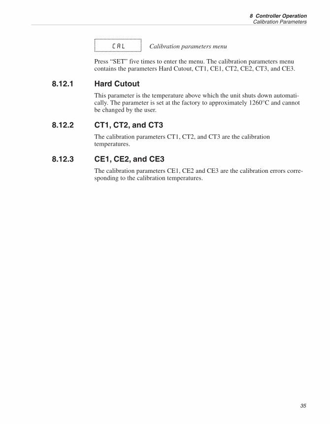
CAL Calibration parameters menu
Press “SET” five times to enter the menu. The calibration parameters menucontains the parameters Hard Cutout, CT1, CE1, CT2, CE2, CT3, and CE3.
8.12.1 Hard CutoutThis parameter is the temperature above which the unit shuts down automati-cally. The parameter is set at the factory to approximately 1260°C and cannotbe changed by the user.
8.12.2 CT1, CT2, and CT3The calibration parameters CT1, CT2, and CT3 are the calibrationtemperatures.
8.12.3 CE1, CE2, and CE3The calibration parameters CE1, CE2 and CE3 are the calibration errors corre-sponding to the calibration temperatures.
35
8 Controller OperationCalibration Parameters
9 Digital Communication Interface
The furnace is capable of communicating with and being controlled by otherequipment through the digital serial interface.
With a digital interface the instrument may be connected to a computer or otherequipment. This allows the user to set the set-point temperature, monitor thetemperature, and access any of the other controller functions, all using remotecommunications equipment. Communications commands are summarized inTable 2 on page 40.
9.1 Serial CommunicationsThe calibrator is installed with an RS-232 serial interface that allows serial dig-ital communications over fairly long distances. With the serial interface the usermay access any of the functions, parameters and settings discussed in Section 8with the exception of the BAUD rate setting.
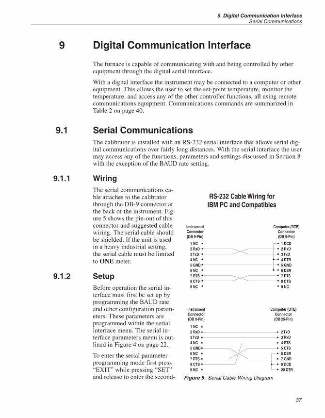
9.1.1 WiringThe serial communications ca-ble attaches to the calibratorthrough the DB-9 connector atthe back of the instrument. Fig-ure 5 shows the pin-out of thisconnector and suggested cablewiring. The serial cable shouldbe shielded. If the unit is usedin a heavy industrial setting,the serial cable must be limitedto ONE meter.
9.1.2 SetupBefore operation the serial in-terface must first be set up byprogramming the BAUD rateand other configuration param-eters. These parameters areprogrammed within the serialinterface menu. The serial in-terface parameters menu is out-lined in Figure 4 on page 22.
To enter the serial parameterprogramming mode first press“EXIT” while pressing “SET”and release to enter the second-
37
9 Digital Communication InterfaceSerial Communications
Figure 5 Serial Cable Wiring Diagram

ary menu. Press “SET” repeatedly until the display reads “CAL”. Press “UP”until the serial interface menu is indicated with “SErIAL”. Finally press “SET”to enter the serial parameter menu. In the serial interface parameters menu arethe BAUD rate, the sample rate, the duplex mode, and the linefeed parameter.
9.1.2.1 BAUD Rate
The BAUD rate is the first parameter in the menu. The display prompts withthe BAUD rate parameter by showing “bAUd”. Press “SET” to choose to setthe BAUD rate. The current BAUD rate value is displayed. The BAUD rate ofthe 9150 serial communications may be programmed to 300, 600, 1200, 2400,4800, or 9600 baud. The BAUD rate is preprogrammed to 2400 BAUD. Use“UP” or “DOWN” to change the BAUD rate value. Press “SET” to set theBAUD rate to the new value or “EXIT” to abort the operation and skip to thenext parameter in the menu.
9.1.2.2 Sample Period
The sample period is the next parameter in the menu and prompted with“SPEr”. The sample period is the time period in seconds between temperaturemeasurements transmitted from the serial interface. If the sample rate is set to5, the instrument transmits the current measurement over the serial interface ap-proximately every five seconds. The automatic sampling is disabled with asample period of 0. Press “SET” to choose to set the sample period. Adjust theperiod with “UP” or “DOWN” and then use “SET” to set the sample rate to thedisplayed value.
9.1.2.3 Duplex Mode
The next parameter is the duplex mode indicated with “dUPL”. The duplexmode may be set to half duplex (“HALF”) or full duplex (“FULL”). With fullduplex any commands received by the thermometer via the serial interface areimmediately echoed or transmitted back to the device of origin. With half du-plex the commands are executed but not echoed. The default setting is full du-plex. The mode may be changed using “UP” or “DOWN” and pressing “SET”.
9.1.2.4 Linefeed
The final parameter in the serial interface menu is the linefeed mode. This pa-rameter enables (“On”) or disables (“OFF”) transmission of a linefeed charac-ter (LF, ASCII 10) after transmission of any carriage-return. The default settingis with linefeed on. The mode may be changed using “UP” or “DOWN” andpressing “SET”.
9.1.3 Serial OperationOnce the cable has been attached and the interface set up properly, the control-ler immediately begins transmitting temperature readings at the programmedrate. The serial communications uses 8 data bits, one stop bit, and no parity.The set-point and other commands may be sent via the serial interface to set the
9150 Portable Furnace
User’s Guide
38
temperature set-point and view or program the various parameters. The inter-face commands are discussed in Section 9.2. All commands are ASCII charac-ter strings terminated with a carriage-return character (CR, ASCII 13).
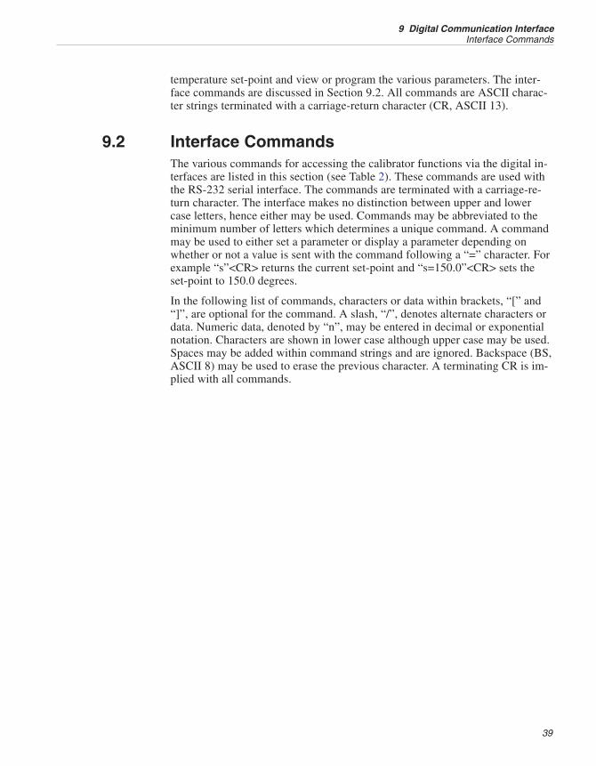
9.2 Interface CommandsThe various commands for accessing the calibrator functions via the digital in-terfaces are listed in this section (see Table 2). These commands are used withthe RS-232 serial interface. The commands are terminated with a carriage-re-turn character. The interface makes no distinction between upper and lowercase letters, hence either may be used. Commands may be abbreviated to theminimum number of letters which determines a unique command. A commandmay be used to either set a parameter or display a parameter depending onwhether or not a value is sent with the command following a “=” character. Forexample “s”<CR> returns the current set-point and “s=150.0”<CR> sets theset-point to 150.0 degrees.
In the following list of commands, characters or data within brackets, “[” and“]”, are optional for the command. A slash, “/”, denotes alternate characters ordata. Numeric data, denoted by “n”, may be entered in decimal or exponentialnotation. Characters are shown in lower case although upper case may be used.Spaces may be added within command strings and are ignored. Backspace (BS,ASCII 8) may be used to erase the previous character. A terminating CR is im-plied with all commands.
39
9 Digital Communication InterfaceInterface Commands

9150 Portable Furnace
User’s Guide
40
Command DescriptionCommandFormat
CommandExample Returned
ReturnedExample
AcceptableValues
Display Temperature
Read current set-point s[etpoint] s set: 9999.99 {C or F} set: 150.0 C
Set current set-point to n s[etpoint]=n s=450 InstrumentRange
Set temperature units: u[nits]=c/f C or F
Set temperature units to Celsius u[nits]=c u=c
Set temperature units toFahrenheit
u[nits]=f u=f
Read scan function sc[an] sc scan: {ON or OFF} scan: ON
Set scan function: sc[an]=on/of[f] ON or OFF
Turn scan function on sc[an]=on sc=on
Turn scan function off sc[an]=of[f] sc=of
Read scan rate sr[ate] sr srat: 999.99 {C or F}/min srat: 10.0 C/min
Set scan rate to n degrees perminute
sr[ate]=n sr=5 .1 to 99.9
Secondary Menu
Read proportional band setting pr[op-band] pr pb: 999.9 pb: 15.9
Set proportional band to n pr[op-band]=n pr=8.83 0.1 to 100
Read heater power(duty cycle)
po[wer] po po: 999.9 po: 1
Ramp and Soak Menu
Read number of programmableset-points
pn pn pn: 9 pn: 2
Set number of programmableset-points to n
pn=n pn=4 1 to 8
Read programmable set-pointnumber n
psn ps3 psn: 9999.99 {C or F} ps1: 50.00 C
Set programmable set-point num-ber n to n
psn=n ps3=50 1 to 8, Instru-ment Range
Read program set-point soaktime
ptn pt3 tin: 999 ti1: 5
Set program set-point soak timeto n minutes
ptn=n pt3=5 0 to 14400
Read program scan rate pxn px3 srn: 99.9 sr3: 11.3
Set program scan rate pxn=n px3=10 .1 to 99.9
Read program control mode pc pc prog: {OFF or ON} prog: OFF
Set program control mode: pc=g[o]/s[top]/c[ont] GO or STOP orCONT
Start program pc=g[o] pc=g
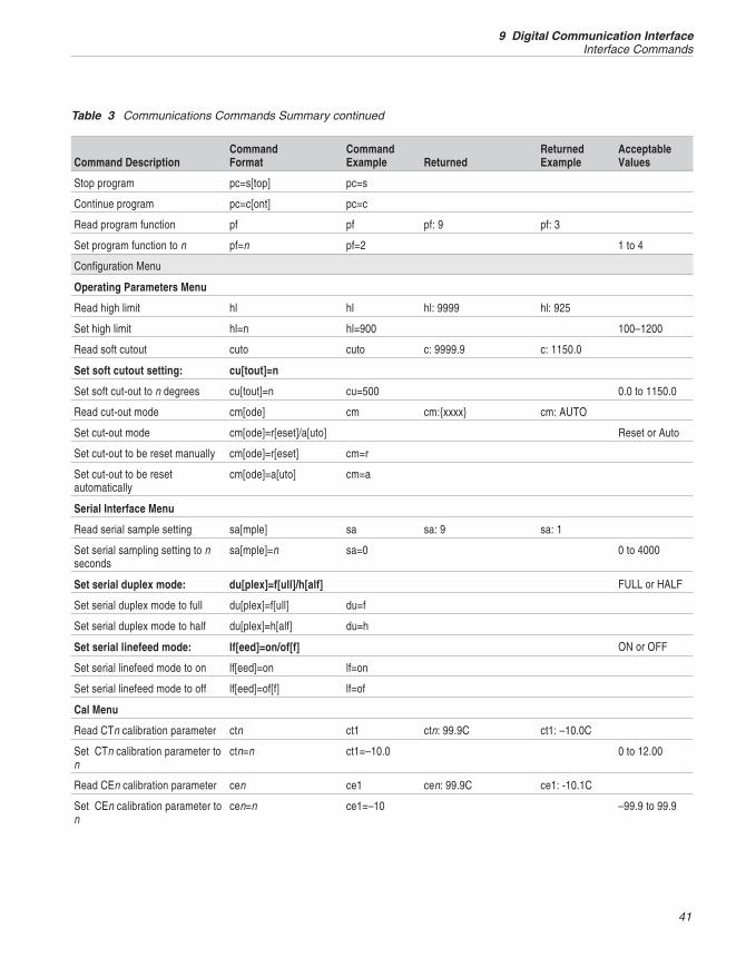
Table 2 Communications Command Summary
41
9 Digital Communication InterfaceInterface Commands
Command DescriptionCommandFormat
CommandExample Returned
ReturnedExample
AcceptableValues
Stop program pc=s[top] pc=s
Continue program pc=c[ont] pc=c
Read program function pf pf pf: 9 pf: 3
Set program function to n pf=n pf=2 1 to 4
Configuration Menu
Operating Parameters Menu
Read high limit hl hl hl: 9999 hl: 925
Set high limit hl=n hl=900 100–1200
Read soft cutout cuto cuto c: 9999.9 c: 1150.0
Set soft cutout setting: cu[tout]=n
Set soft cut-out to n degrees cu[tout]=n cu=500 0.0 to 1150.0
Read cut-out mode cm[ode] cm cm:{xxxx} cm: AUTO
Set cut-out mode cm[ode]=r[eset]/a[uto] Reset or Auto
Set cut-out to be reset manually cm[ode]=r[eset] cm=r
Set cut-out to be resetautomatically
cm[ode]=a[uto] cm=a
Serial Interface Menu
Read serial sample setting sa[mple] sa sa: 9 sa: 1
Set serial sampling setting to nseconds
sa[mple]=n sa=0 0 to 4000
Set serial duplex mode: du[plex]=f[ull]/h[alf] FULL or HALF
Set serial duplex mode to full du[plex]=f[ull] du=f
Set serial duplex mode to half du[plex]=h[alf] du=h
Set serial linefeed mode: lf[eed]=on/of[f] ON or OFF
Set serial linefeed mode to on lf[eed]=on lf=on
Set serial linefeed mode to off lf[eed]=of[f] lf=of
Cal Menu
Read CTn calibration parameter ctn ct1 ctn: 99.9C ct1: –10.0C
Set CTn calibration parameter ton
ctn=n ct1=–10.0 0 to 12.00
Read CEn calibration parameter cen ce1 cen: 99.9C ce1: -10.1C
Set CEn calibration parameter ton
cen=n ce1=–10 –99.9 to 99.9
Table 3 Communications Commands Summary continued

9150 Portable Furnace
User’s Guide
42
Command DescriptionCommandFormat
CommandExample Returned
ReturnedExample
AcceptableValues
These commands are only used for factory testing.
Miscellaneous (not on menus)
Read firmware version number *ver[sion] *ver ver.9999,9.99 ver.9150,2.20
Read structure of all commands h[elp] h list of commands
Legend: [] Optional Command data
{} Returns either information
n Numeric data supplied by user
9 Numeric data returned to user
x Character data returned to user
Note: When DUPLEX is set to FULL and a command is sent to READ, the command is returned followed by acarriage return and linefeed. Then the value is returned as indicated in the RETURNED column.
Table 4 Communications Commands Summary continued

10 Test Probe Calibration
For optimum accuracy and stability, allow the calibrator to warm up for 10minutes after power-up and then allow adequate stabilization time after reach-ing the set-point temperature. After completing operation of the calibrator, al-low the well to cool by setting the temperature to 150°C or less for one-halfhour before switching the power off.
10.1 Calibrating a Single ProbeInsert the probe to be calibrated into the well of the furnace calibrator. Theprobe should fit snugly into the calibrator probe sleeve yet should not be sotight that it cannot be easily removed. Avoid any dirt or grit that may cause theprobe to jam into the sleeve. Best results are obtained with the probe inserted tothe full depth of the well. Once the probe is inserted into the well, allow ade-quate stabilization time to allow the test probe temperature to settle as de-scribed above. Once the probe has settled to the temperature of the well, it maybe compared to the calibrator display temperature. The display temperatureshould be stable to within 1°C degree for best results.
CAUTION: Never introduce any foreign material into the probe hole ofthe insert. Fluids etc. can leak into the calibrator causing damage to thecalibrator or binding and damage to your probe.
10.2 Furnace CharacteristicsThere is a temperature gradient vertically in the test well. The heater has beenapplied to the block in such a way as to compensate for nominal heat losses outof the top of the furnace. However, actual heat losses will vary with design ofthe thermometer probes inserted into the calibrator and the temperature. Forbest results, insert probe to full depth of well.
CAUTION: Do not remove inserts and insulators at high temperatures.Inserts and insulators are the same temperature as the display tempera-ture. Use extreme care when removing hot inserts and insulators.
10.2.1 Stabilization and AccuracyThe stabilization time of the calibrator depends on the conditions and tempera-tures involved. Typically the test well is stable to 0.5°C within 20 minutes ofreaching the set-point temperature as indicated by the display. Ultimate stabilityis achieved 10 to 20 minutes after reaching the set temperature.
Inserting a cold probe into a well requires another period of stabilizing depend-ing on the magnitude of the disturbance and the required accuracy. For exam-ple, inserting a .25 inch diameter room temperature probe into a sleeve at
43
10 Test Probe CalibrationCalibrating a Single Probe

1200°C takes 10 minutes to be within 0.5°C of its settled point and takes 15minutes to achieve maximum stability.
Speeding up the calibration process can be accomplished by knowing how soonto make the measurement. It is recommended that typical measurements bemade at the desired temperatures with the desired test probes to establish thesetimes.
9150 Portable Furnace
User’s Guide
44

11 Calibration Procedure
At times the user may want to calibrate the unit to improve the temperatureset-point accuracy. Calibration is done by adjusting the controller probe cali-bration constants CE1, CE2, and CE3 so that the temperature of the unit asmeasured with a standard thermocouple agrees more closely with the set-point.The thermometer used must be able to measure the well temperature withhigher accuracy than the desired accuracy of the unit.
11.1 Calibration PointsIn calibrating the unit, CE1, CE2, and CE3 are adjusted to minimize theset-point error at each of three different well temperatures. Any three reason-ably separated temperatures may be used for the calibration. Improved resultscan be obtained for shorter ranges when using temperatures that are just withinthe most useful operating range of the unit. The farther apart the calibrationtemperatures, the larger the calibration range but the calibration error is alsogreater over the range. Choosing a range of 150°C to 500°C may allow the cali-brator to have a better accuracy of maybe ±2.0°C but outside that range the ac-curacy may be greater than ±10.0°C.
11.2 Calibration Procedure1. Choose three set-points to use in the calibration of CE1, CE2, and CE3
parameters. These set-points are generally CT1 = 150°C, CT2 = 675°Cand CT3 = 1200°C but other set-points may be used if desired or neces-sary. Using these three temperature set-points may result in ±4.0°Caccuracy.
2. If the normal set-points are not used, initialize CT1, CT2, and CT3 to thedesired set points. Where CT1 is the low-set point and CT3 is the highset-point.
3. Set the unit to the low set-point. When the unit reaches the set-point andthe display is stable, wait 15 minutes or so and take a reading from thethermometer. Repeat step 3 for the other two set-points recording themas Tm1, Tm2, and Tm3.
4. Retrieve the original calibration errors from the unit or the Report ofCalibration.
5. Record the previous values for CE1, CE2, and CE3 and calculate newvalues for CE1, CE2, and CE3 using the following formula.
Tmn –Tsn +CEn = CEm
Where:
Tmn is the temperature measured, Tsn (CTn) is the set-point tempera-
45
11 Calibration ProcedureCalibration Points

ture, CEn is the old value for calibration error, and CEm is the new valuefor calibration error
6. Enter the new CEm value in the calibration parameter menu using eitherthe keypad or through the serial port.
9150 Portable Furnace
User’s Guide
46

12 Maintenance
• The calibration instrument has been designed with the utmost care. Easeof operation and simplicity of maintenance have been a central theme inthe product development. Therefore, with proper care the instrumentshould require very little maintenance. Avoid operating the instrument inan oily, wet, dirty, or dusty environment.
• If the outside of the instrument becomes soiled, it may be wiped cleanwith a damp cloth and mild detergent. Do not use harsh chemicals on thesurface which may damage the paint.
• Be sure that the well of the furnace is kept clean and clear of any foreignmatter. DO NOT use fluids to clean out the well.
• If a hazardous material is split on or inside the equipment, the user is re-sponsible for taking the appropriate decontamination steps as outlined bythe national safety council with respect to the material.
• If the mains supply cord becomes damaged, replace it with a cord of theappropriate gauge wire for the current of the instrument. If there are anyquestions, call Hart Scientific Customer Service for more information.
• Before using any cleaning or decontamination method except those rec-ommended by Hart, users should check with Hart Scientific CustomerService to be sure that the proposed method will not damage the equip-ment.
• If the instrument is used in a manner not in accordance with the equip-ment design, the operation of the furnace may be impaired or safety haz-ards may arise.
• The over-temperature cutout should be checked every 6 months to see thatit is working properly.
47
12 Maintenance
13 Troubleshooting
This section contains information on troubleshooting, CE Comments, and awiring diagram.
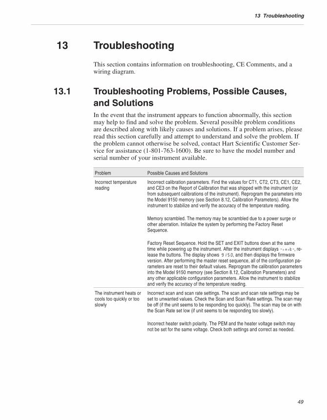
13.1 Troubleshooting Problems, Possible Causes,and SolutionsIn the event that the instrument appears to function abnormally, this sectionmay help to find and solve the problem. Several possible problem conditionsare described along with likely causes and solutions. If a problem arises, pleaseread this section carefully and attempt to understand and solve the problem. Ifthe problem cannot otherwise be solved, contact Hart Scientific Customer Ser-vice for assistance (1-801-763-1600). Be sure to have the model number andserial number of your instrument available.
Problem Possible Causes and Solutions
Incorrect temperaturereading
Incorrect calibration parameters. Find the values for CT1, CT2, CT3, CE1, CE2,and CE3 on the Report of Calibration that was shipped with the instrument (orfrom subsequent calibrations of the instrument). Reprogram the parameters intothe Model 9150 memory (see Section 8.12, Calibration Parameters). Allow theinstrument to stabilize and verify the accuracy of the temperature reading.
Memory scrambled. The memory may be scrambled due to a power surge orother aberration. Initialize the system by performing the Factory ResetSequence.
Factory Reset Sequence. Hold the SET and EXIT buttons down at the sametime while powering up the instrument. After the instrument displays -init-, re-lease the buttons. The display shows 9150, and then displays the firmwareversion. After performing the master reset sequence, all of the configuration pa-rameters are reset to their default values. Reprogram the calibration parametersinto the Model 9150 memory (see Section 8.12, Calibration Parameters) andany other applicable configuration parameters. Allow the instrument to stabilizeand verify the accuracy of the temperature reading.
The instrument heats orcools too quickly or tooslowly
Incorrect scan and scan rate settings. The scan and scan rate settings may beset to unwanted values. Check the Scan and Scan Rate settings. The scan maybe off (if the unit seems to be responding too quickly). The scan may be on withthe Scan Rate set low (if unit seems to be responding too slowly).
Incorrect heater switch polarity. The PEM and the heater voltage switch maynot be set for the same voltage. Check both settings and correct as needed.
49
13 Troubleshooting

Problem Possible Causes and Solutions
The display shows any ofthe following: err 1 ,err 2 , err 3, err4 , Err 5, Err 6,Err 7, or Err 8
Controller problem. The error messages signify the following problems with thecontroller.Err 1 - a RAM errorErr 2 - a NVRAM errorErr 3 - a RAM errorErr 4 - an ADC setup errorErr 5 - an ADC ready errorErr 6 – a Sensor errorErr 7 – a Heater control errorErr 8 – a Soft cutout errorInitialize the system by performing the Factory Reset Sequence describeabove.
Temperature cannot beset above a certain point
Incorrect High Limit parameter. The High Limit parameter may be set below1200°C. Check this value as described in Section 8.10, Operating Parameters.
The display flashesCut-out
Incorrect Soft Cutout parameter. Wait for the instrument to cool and adjust theSoft Cutout parameter as described in Section 8.10, Operating Parameters.
13.2 Comments
13.2.1 EMC DirectiveEquipment manufactured by Hart Scientific has been tested to meet the Euro-pean Electromagnetic Compatibility Directive (EMC Directive, 89/336/EEC).The Declaration of Conformity for your instrument lists the specific standardsto which the unit was tested.
13.2.2 Low Voltage Directive (Safety)In order to comply with the European Low Voltage Directive (73/23/EEC),Hart Scientific equipment has been designed to meet the IEC 1010-1 (EN61010-1) and the IEC 1010-2-010 (EN 61010-2-010) standards.
9150 Portable Furnace
User’s Guide
50