9200 df assembly-parts 760000256 rev0
TRANSCRIPT

Kon
gski
lde
9200KONGSKILDE 9200 DF
Vertical Tillage - Assembly/Parts
Models769243901 9243 Vertical Tillage (43') 760000256 - Revision 0
Serial No. 500011 - current
*Model may not be exactly as shown.Kongskilde reserves the right to make changes to product designs and specifications without notice or obligation to rework.See your local Kongskilde representative for current product specific-ations and options.

2
Introduction: ........................................................................................................................................3Mainframe & Gang Tube Assembly ....................................................................................................4Center Rockshaft Assembly .................................................................................................................6Center Rockshaft Part Details ..............................................................................................................8Center Lift Cylinders & Linkage Assembly ......................................................................................10Single Point Assembly .......................................................................................................................12Hitch & Turnbuckle Assembly ..........................................................................................................14Light Stands & Safety Lock Assembly ..............................................................................................16Center Gang & Scraper Assembly .....................................................................................................18Gang Assembly Details ......................................................................................................................20Inner Wing & Gang Tube Assembly ..................................................................................................22Inner Wing Fold Cylinder Assembly .................................................................................................24Inner Wing Wheelarm & Cylinder Assembly ....................................................................................26Wing Wheelarm Part Details .............................................................................................................28Inner Wing Gang & Scraper Assembly ..............................................................................................30Outer Wing & Gang Tube Assembly .................................................................................................32Outer Wing Fold Cylinder Assembly .................................................................................................34Outer Wing Wheelarm & Cylinder Assembly ...................................................................................36Outer Wing Gang & Scraper Assembly .............................................................................................38Harrow Arm & Roller Assembly .......................................................................................................40Hydraulic Tree Assembly ...................................................................................................................42Lift Hydraulics ...................................................................................................................................44Fold Hydraulics ..................................................................................................................................46Cylinder Parts .....................................................................................................................................48Light Kit Assemby .............................................................................................................................50Swivel Gauge Wheel Assembly (Optional) .......................................................................................52Decal Placement .................................................................................................................................54Assembly Completion ........................................................................................................................56Appendix A - Hose Routing ...............................................................................................................57Appendix B - Light Wire Routing .....................................................................................................59Appendix C - Gang Layout ................................................................................................................60Appendix D - Roller Layout ..............................................................................................................61Appendix E - Torque Chart ................................................................................................................62
Table of Contents

3
Introduction:
Please take the time to carefully read all the instruction booklets provided with your new Kongskilde product. Once you are finished reading do not throw these guides out. Keep them for later review.
These instruction booklets have been developed to assist you in assembling, adjusting and maintain-ing your new Kongskilde Product. To obtain optimal performance over the lifetime of the product read and follow these instructions carefully.
When the assembly of the unit is completed, please refer to the Owners Manual before attempting to adjust or use the product. The Owners Manual will provide you with further instructions on the proper Field Settings, Adjustments and Maintenance Procedures for Safe Operation of the unit.
If optional equipment or attachments have been ordered for your unit, please refer to the instruction booklets provided for proper installation and adjustment of these accessories.
Please take the time to fill out and return the Owners Registration and Warranty Form provided with the Owners Manual in order to activate the warranty coverage.
NOTES:-Images in this manual are for reference only and may not exactly match actual components.-This manual depicts "Left" and "Right" as if standing behind the unit facing forward.-Refer to torque chart in Appendix E for proper tightening of bolts, unless otherwise noted.
4
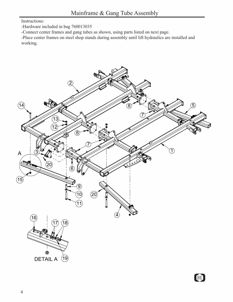
Mainframe & Gang Tube AssemblyInstructions:-Hardware included in bag 760013035-Connect center frames and gang tubes as shown, using parts listed on next page.-Place center frames on steel shop stands during assembly until lift hydraulics are installed and working.
� �
�
�
�
�
�
�
�
�
�
��
��
��
��
��
��
��
��
�
���������
���� ��
��

5
Parts List / 9200 DF Mainframe & Gang Tube Assembly. Date: April 2015 Fig. Part no. Qty Description
1 760013054 1 Center Mainframe Assembly, LH2 760013055 1 Center Mainframe Assembly, RH3 760013060 1 Leveling Pivot Linkage Mount Assembly4 760013061 2 Gang Tube Assembly, Front Center5 760013062 2 Gang Tube Assembly, Rear Center6 600356102 2 Hex Bolt, 1" x 4-1/2" GR. 57 600356004 10 Hex Bolt, 1" x 3-1/2" GR. 58 600366032 12 Nut, Toplock 1"9 760015081 4 Bushing, Gang Pivot10 7600381056 4 Flat Washer, 1-1/4" Hardened GR. 911 7600355104 4 Hex Bolt, 1-1/4" x 10" GR. 812 7600382104 4 Lock Washer, 1-1/4"13 600365064 4 Nut, Standard 1-1/4" GR. 814 600355054 4 Hex Bolt, 1" x 6-1/2" GR. 815 7600366052 4 Flange Nut, Spiralock 1"16 600356011 4 Hex Bolt, 3/4" x 2-1/2" GR. 5 (Full Thread)17 600381009 8 Flat Washer, 3/4"18 7600365080 8 Jam Nut, 3/4"19 100401006 4 Bearing, Gang Adjust20 600471000 5 Grease Fitting (pre-installed)

6
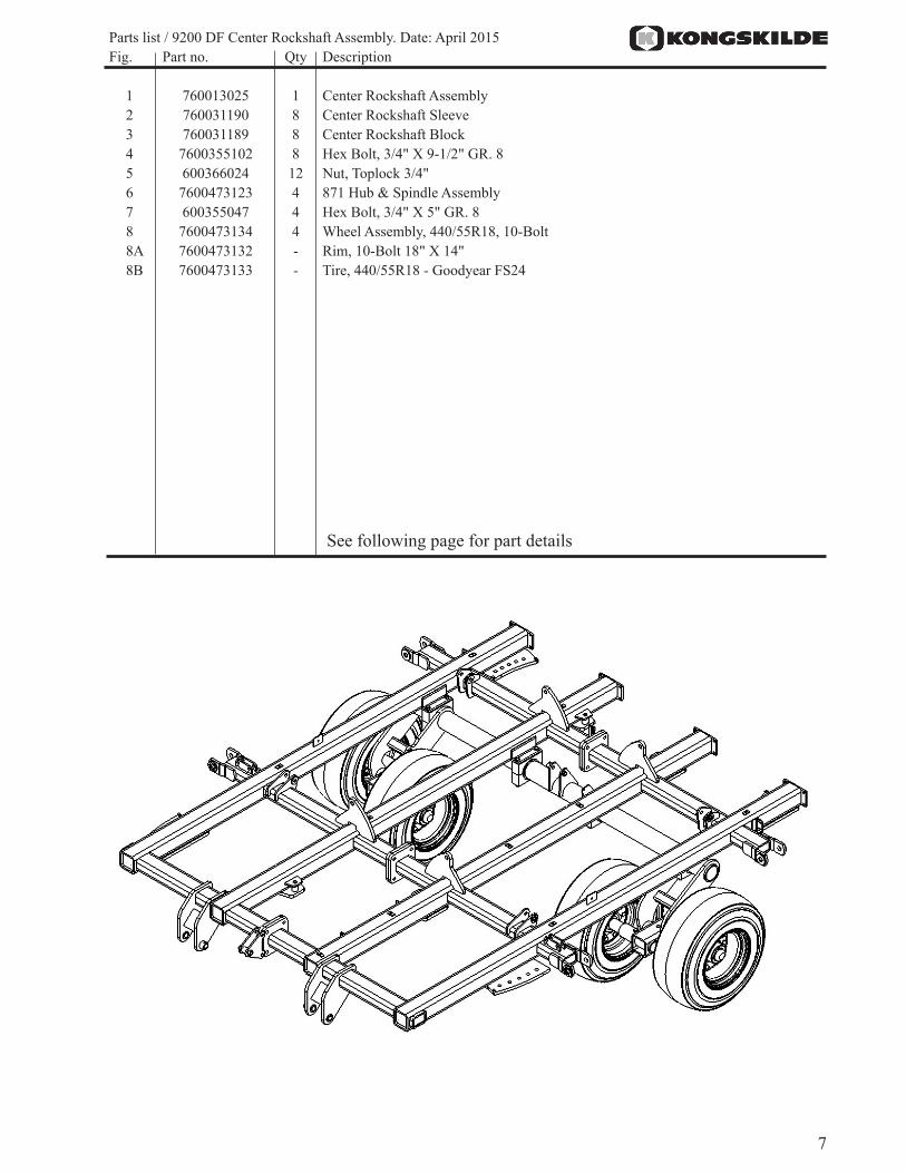
Instructions:-Hardware included in bag 760013038-Insert wear sleeves into rockshaft blocks before assembling rockshaft.-Assemble rockshaft, spindles and wheels to center frame as shown, using parts listed on next page.-IMPORTANT: Install wheels to the spindles so the wheel rims are offset toward the wheel arms (Narrow setting). Torque lug nuts to 310 ft-lbs. Re-torque lug nuts after 10 hours of field use and check every 50 hours.
Center Rockshaft Assembly
�
�
�
�
�
�
�
�
�
7
Parts list / 9200 DF Center Rockshaft Assembly. Date: April 2015 Fig. Part no. Qty Description
1 760013025 1 Center Rockshaft Assembly2 760031190 8 Center Rockshaft Sleeve3 760031189 8 Center Rockshaft Block4 7600355102 8 Hex Bolt, 3/4" X 9-1/2" GR. 85 600366024 12 Nut, Toplock 3/4"6 7600473123 4 871 Hub & Spindle Assembly7 600355047 4 Hex Bolt, 3/4" X 5" GR. 88 7600473134 4 Wheel Assembly, 440/55R18, 10-Bolt8A 7600473132 - Rim, 10-Bolt 18" X 14"8B 7600473133 - Tire, 440/55R18 - Goodyear FS24
See following page for part details
8
Center Rockshaft Part Details
�
� � � �
�
��
�����
��
��
��
��
����
��
��
��
��
��
��
����
��
����
��
9
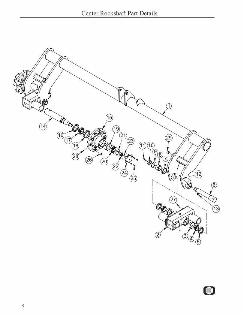
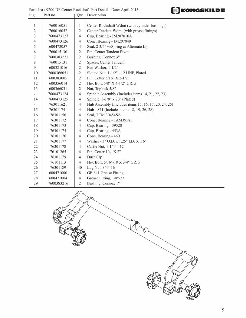
Parts list / 9200 DF Center Rockshaft Part Details. Date: April 2015 Fig. Part no. Qty Description
1 760016051 1 Center Rockshaft Wdmt (with cylinder bushings)2 760016052 2 Center Tandem Wdmt (with grease fittings)3 7600473127 4 Cup, Bearing - JM207010A4 7600473126 4 Cone, Bearing - JM2070495 600473057 4 Seal, 2-3/4" w/Spring & Alternate Lip6 760015130 2 Pin, Center Tandem Pivot7 7600383221 2 Bushing, Connex 3"8 760015131 2 Spacer, Center Tandem9 600381016 2 Flat Washer, 1-1/2"10 7600366051 2 Slotted Nut, 1-1/2" - 12 UNF, Plated11 600383005 2 Pin, Cotter 5/16" X 2-1/2"12 600356014 2 Hex Bolt, 5/8" X 4-1/2" GR. 513 600366031 2 Nut, Toplock 5/8"- 7600473124 4 Spindle Assembly (Includes items 14, 21, 22, 23)14 7600473125 4 Spindle, 3-1/8" x 20" (Plated)- 763011621 4 Hub Assembly (Includes items 15, 16, 17, 20, 24, 25)15 763011741 4 Hub - 871 (Includes items 18, 19, 26, 28)16 76301156 4 Seal, TCM 30454SA17 76301172 4 Cone, Bearing - TAM3958518 76301173 4 Cup, Bearing - 3952019 76301175 4 Cup, Bearing - 453A20 76301176 4 Cone, Bearing - 46021 76301177 4 Washer - 3" O.D. x 1.25" I.D. X .16"22 76301178 4 Castle Nut, 1-1/4" - 1223 76101265 4 Pin, Cotter 1/4" X 2"24 76301179 4 Dust Cap 25 76101113 4 Hex Bolt, 5/16"-18 X 3/4" GR. 526 76301189 40 Lug Nut, 3/4"-1627 600471000 8 GF-641 Grease Fitting28 600471004 4 Grease Fitting, 1/8"-2729 7600383216 2 Bushing, Connex 1"
10
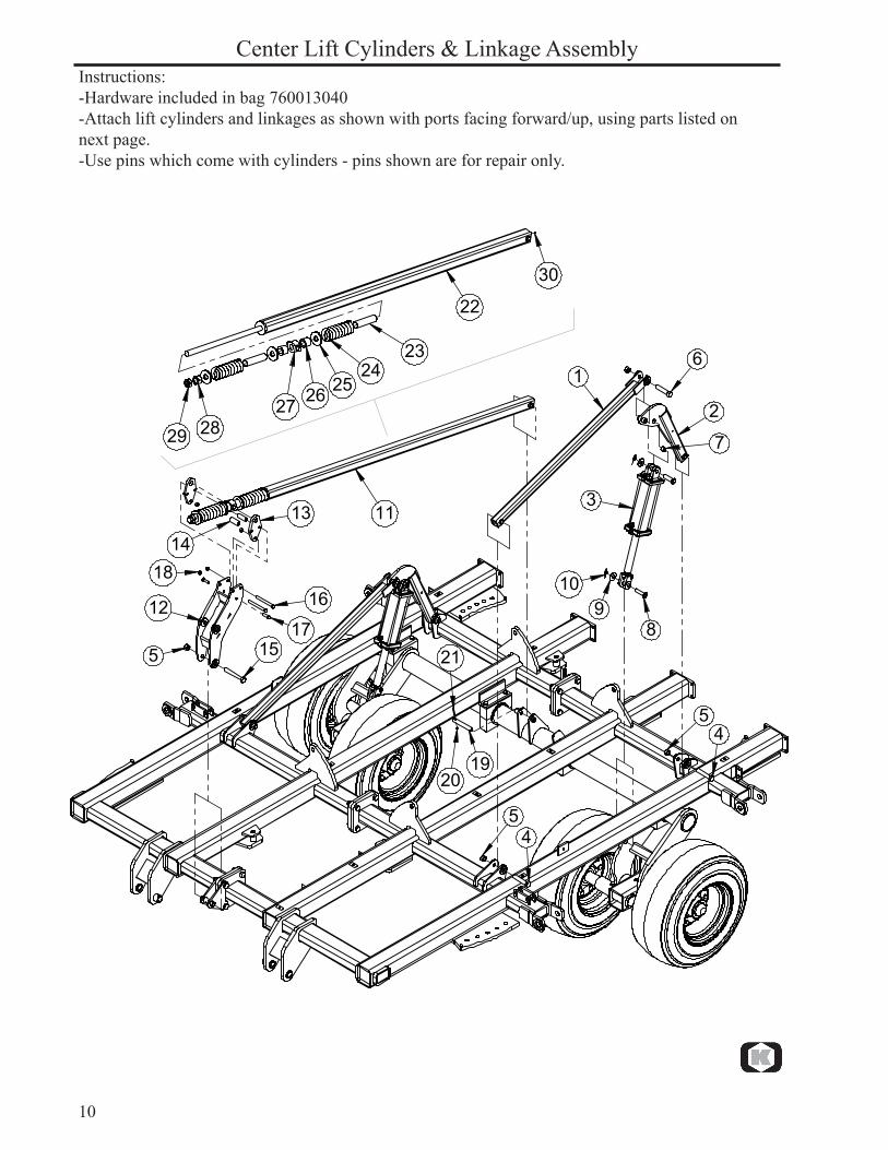
Instructions:-Hardware included in bag 760013040-Attach lift cylinders and linkages as shown with ports facing forward/up, using parts listed on next page.-Use pins which come with cylinders - pins shown are for repair only.
Center Lift Cylinders & Linkage Assembly
�
�
�
��
�
�
��
��
��
��
���
��
��
��
����
��
��
��
��
��
����
����������
��

11
Parts list / 9200 DF Fold Center Lift Cylinders & Linkage Asy. Date: April 2015 Fig. Part no. Qty Description
1 760016029 2 Center Linkage Tube2 760013067 2 Rear Cylinder Linkage (Includes Item 7)3 600474633 2 Cylinder, 4-1/2" X 12"4 600356029 4 Hex Bolt, 1" X 5-1/2" GR. 55 600366032 7 Nut, Toplock 1"6 600356101 2 Hex Bolt, 1" X 5" GR. 57 7600383216 2 Bushing, Connex 1"8 600383136 4 Pin, 1" X 85mm9 600381018 4 Flat Washer, 1"10 600383058 4 Pin, Cotter 5/32" X 2"11 760013026 1 Self-Leveling Cushion Assembly (Includes Items 22-30)12 760016055 1 Leveling Pivot Linkage13 760015195 2 HD Trunnion Plate14 760015187 2 Self-Leveling Pivot Spacer15 7600355109 1 Hex Bolt, 1" X 7-1/2" GR. 816 600355032 2 Hex Bolt, 5/8" X 6-1/2" GR. 817 600356010 2 Hex Bolt, 5/8" X 2" GR. 518 600366031 4 Nut, Toplock 5/8"19 760031114 1 Pin, Leveling Link20 600366028 1 Nut, Toplock 3/8"21 600356111 1 Hex Bolt, 3/8" X 2" GR. 522 760016072 1 Self-Leveling Tube23 760015194 2 Spring Sleeve24 760015188 2 HD Leveling Spring25 760015193 3 Washer, Leveling26 760011003 2 Trunnion Spacer27 760015189 1 HD Trunnion28 600365022 1 Nut, Standard 1-1/2"-629 600365069 1 Nut, Jam 1-1/2"-630 600471000 1 Grease Fitting

12
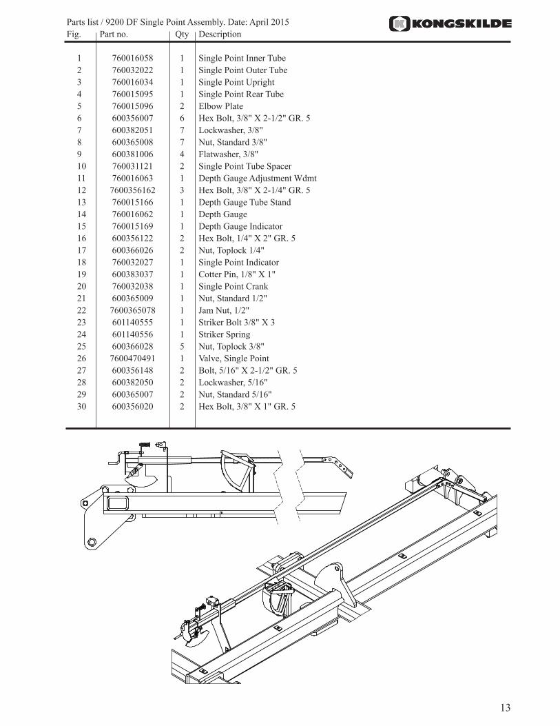
Instructions:-Hardware included in bag 760013041-Assemble parts to frame as shown, using hardware listed on next page.-Slide outer tube (2) over inner tube (1) and insert through upright bracket (3) before bolting on rear tube (4). Connect rear tube to inner tube using 4 holes closest to the bend on the elbow plates (5)
Single Point Assembly
1
23
4
56
78
6
6
9
10
10
9
9
11
12
12
13
14
15
17
18 19
202122
232425
25
25
26
27
2829
78
30
16
78
13
Parts list / 9200 DF Single Point Assembly. Date: April 2015 Fig. Part no. Qty Description
1 760016058 1 Single Point Inner Tube2 760032022 1 Single Point Outer Tube 3 760016034 1 Single Point Upright4 760015095 1 Single Point Rear Tube 5 760015096 2 Elbow Plate6 600356007 6 Hex Bolt, 3/8" X 2-1/2" GR. 57 600382051 7 Lockwasher, 3/8"8 600365008 7 Nut, Standard 3/8"9 600381006 4 Flatwasher, 3/8"10 760031121 2 Single Point Tube Spacer11 760016063 1 Depth Gauge Adjustment Wdmt12 7600356162 3 Hex Bolt, 3/8" X 2-1/4" GR. 513 760015166 1 Depth Gauge Tube Stand14 760016062 1 Depth Gauge15 760015169 1 Depth Gauge Indicator16 600356122 2 Hex Bolt, 1/4" X 2" GR. 517 600366026 2 Nut, Toplock 1/4"18 760032027 1 Single Point Indicator19 600383037 1 Cotter Pin, 1/8" X 1"20 760032038 1 Single Point Crank21 600365009 1 Nut, Standard 1/2"22 7600365078 1 Jam Nut, 1/2"23 601140555 1 Striker Bolt 3/8" X 324 601140556 1 Striker Spring25 600366028 5 Nut, Toplock 3/8"26 7600470491 1 Valve, Single Point27 600356148 2 Bolt, 5/16" X 2-1/2" GR. 528 600382050 2 Lockwasher, 5/16"29 600365007 2 Nut, Standard 5/16"30 600356020 2 Hex Bolt, 3/8" X 1" GR. 5
14
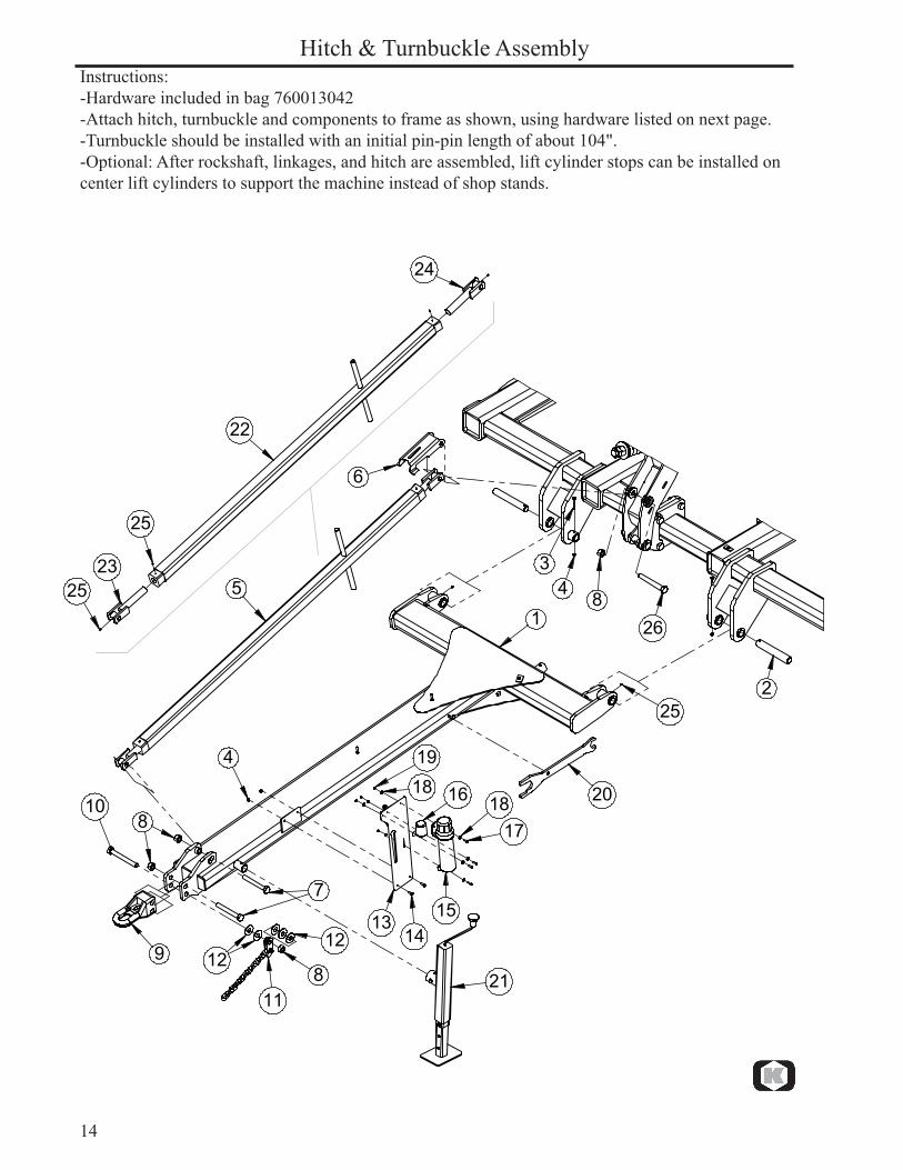
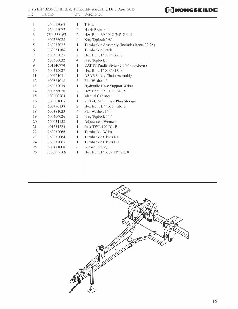
Instructions:-Hardware included in bag 760013042-Attach hitch, turnbuckle and components to frame as shown, using hardware listed on next page.-Turnbuckle should be installed with an initial pin-pin length of about 104".-Optional: After rockshaft, linkages, and hitch are assembled, lift cylinder stops can be installed on center lift cylinders to support the machine instead of shop stands.
Hitch & Turnbuckle Assembly
�
�
���
�
���
�
�
�
��
��
��
����
�
��
��
����
���� ��
��
��
��
�
��
��
��
��
��
15
Parts list / 9200 DF Hitch & Turnbuckle Assembly. Date: April 2015 Fig. Part no. Qty Description
1 760013068 1 T-Hitch2 760015072 2 Hitch Pivot Pin3 7600356163 2 Hex Bolt, 3/8" X 2-3/4" GR. 54 600366028 4 Nut, Toplock 3/8"5 760033027 1 Turnbuckle Assembly (Includes Items 22-25)6 760031186 1 Turnbuckle Latch7 600355025 2 Hex Bolt, 1" X 7" GR. 88 600366032 4 Nut, Toplock 1" 9 601140770 1 CAT IV Pindle Style - 2 1/4" (no clevis)10 600355027 1 Hex Bolt, 1" X 8" GR. 811 600461011 1 ASAE Safety Chain Assembly12 600381018 5 Flat Washer 1"13 760032039 1 Hydraulic Hose Support Wdmt14 600356020 2 Hex Bolt, 3/8" X 1" GR. 515 600600268 1 Manual Canister16 760001005 1 Socket, 7-Pin Light Plug Storage17 600356138 2 Hex Bolt, 1/4" X 1" GR. 518 600381023 4 Flat Washer, 1/4"19 600366026 2 Nut, Toplock 1/4"20 760031152 1 Adjustment Wrench21 601231223 1 Jack TWL 190 DL-B22 760032066 1 Turnbuckle Wdmt23 760032064 1 Turnbuckle Clevis RH24 760032065 1 Turnbuckle Clevis LH25 600471000 6 Grease Fitting26 7600355109 1 Hex Bolt, 1" X 7-1/2" GR. 8
16
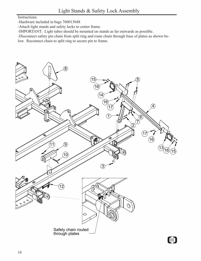
Instructions:-Hardware included in bags 760013048-Attach light stands and safety locks to center frame.-IMPORTANT: Light tubes should be mounted on stands as far outwards as possible.-Disconnect safety pin chain from split ring and route chain through base of plates as shown be-low. Reconnect chain to split ring to secure pin to frame.
Light Stands & Safety Lock Assembly
�
�
�
�
�
��
�
�
��
��
��
��
��
����
��
��
����
����
���������������������������������
17
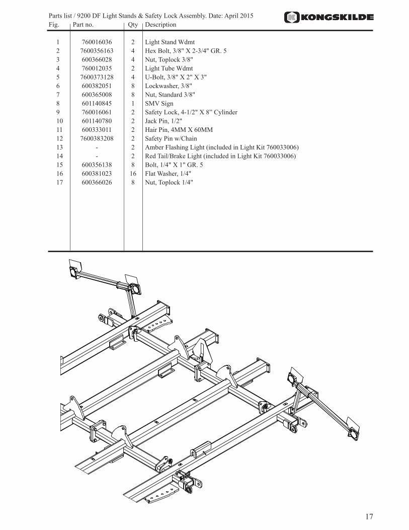
Parts list / 9200 DF Light Stands & Safety Lock Assembly. Date: April 2015 Fig. Part no. Qty Description
1 760016036 2 Light Stand Wdmt2 7600356163 4 Hex Bolt, 3/8" X 2-3/4" GR. 53 600366028 4 Nut, Toplock 3/8"4 760012035 2 Light Tube Wdmt5 7600373128 4 U-Bolt, 3/8" X 2" X 3"6 600382051 8 Lockwasher, 3/8"7 600365008 8 Nut, Standard 3/8"8 601140845 1 SMV Sign9 760016061 2 Safety Lock, 4-1/2" X 8” Cylinder10 601140780 2 Jack Pin, 1/2"11 600333011 2 Hair Pin, 4MM X 60MM12 7600383208 2 Safety Pin w/Chain13 - 2 Amber Flashing Light (included in Light Kit 760033006)14 - 2 Red Tail/Brake Light (included in Light Kit 760033006)15 600356138 8 Bolt, 1/4" X 1" GR. 516 600381023 16 Flat Washer, 1/4"17 600366026 8 Nut, Toplock 1/4"

18
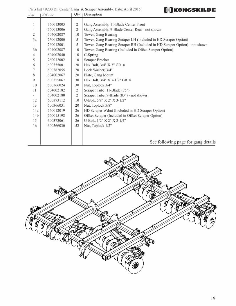
Instructions:-Hardware included in bags 760013044, 760013046, 760013047-Attach bearing towers (2 & 3), c-springs (4), and scraper bracket (5) to gang assemblies using hard-ware listed on next page. Torque bolts (6) to 300 ft-lbs. NOTE: Rotate gang bearing so grease fit-ting is facing rearwards.-Attach gang & c-sping assembly to gang tubes using clamp plates and bolts shown. See Appendix C (pg 60) for gang layout details.-Install scraper tubes and scrapers after gangs have been mounted to machine. NOTE: Offset scrap-ers should be mounted as close as possible (without touching) to the concave side of the blades .
Center Gang & Scraper Assembly
��
��
�
�
��
�
�
��
��
��
��
���
����
��
���
��
��
19
Parts list / 9200 DF Center Gang & Scraper Assembly. Date: April 2015 Fig. Part no. Qty Description
1 760013003 2 Gang Assembly, 11-Blade Center Front- 760013006 2 Gang Assembly, 9-Blade Center Rear - not shown 2 604002087 10 Tower, Gang Bearing3a 760012000 5 Tower, Gang Bearing Scraper LH (Included in HD Scraper Option)- 760012001 5 Tower, Gang Bearing Scraper RH (Included in HD Scraper Option) - not shown3b 604002087 10 Tower, Gang Bearing (Included in Offset Scraper Option)4 604002040 10 C-Spring5 760012002 10 Scraper Bracket 6 600355001 20 Hex Bolt, 3/4" X 3" GR. 87 600382055 20 Lock Washer, 3/4"8 604002067 20 Plate, Gang Mount9 600355067 30 Hex Bolt, 3/4" X 7-1/2" GR. 810 600366024 30 Nut, Toplock 3/4"11 604002182 2 Scraper Tube, 11-Blade (75")- 604002180 2 Scraper Tube, 9-Blade (83") - not shown12 600373112 10 U-Bolt, 5/8" X 2" X 3-1/2"13 600366031 20 Nut, Toplock 5/8"14a 760012019 26 HD Scraper Wdmt (Included in HD Scraper Option)14b 760015198 26 Offset Scraper (Included in Offset Scraper Option)15 600373061 26 U-Bolt, 1/2" X 2" X 3-1/4"16 600366030 52 Nut, Toplock 1/2"
See following page for gang details

20
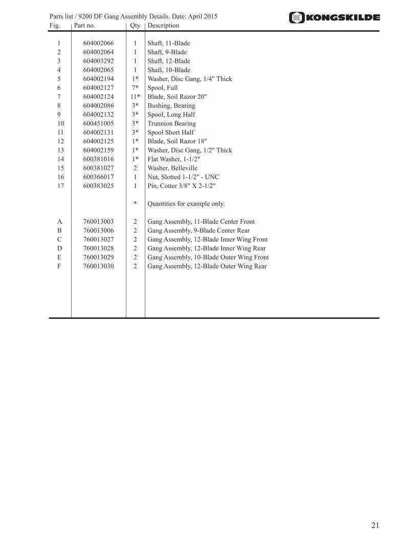
NOTE: The only gang assemblies with an 18" end blade are E & F.
Gang Assemby Details
�
� �
��
� �����
�
��
��
��
��
��
�
�
�
�
�
�
�
�
��
�
���
21
Parts list / 9200 DF Gang Assembly Details. Date: April 2015 Fig. Part no. Qty Description
1 604002066 1 Shaft, 11-Blade 2 604002064 1 Shaft, 9-Blade3 604003292 1 Shaft, 12-Blade 4 604002065 1 Shaft, 10-Blade5 604002194 1* Washer, Disc Gang, 1/4" Thick6 604002127 7* Spool, Full7 604002124 11* Blade, Soil Razor 20"8 604002086 3* Bushing, Bearing9 604002132 3* Spool, Long Half10 600451005 3* Trunnion Bearing11 604002131 3* Spool Short Half12 604002125 1* Blade, Soil Razor 18"13 604002159 1* Washer, Disc Gang, 1/2" Thick14 600381016 1* Flat Washer, 1-1/2"15 600381027 2 Washer, Belleville16 600366017 1 Nut, Slotted 1-1/2" - UNC17 600383025 1 Pin, Cotter 3/8" X 2-1/2"
* Quantities for example only.
A 760013003 2 Gang Assembly, 11-Blade Center FrontB 760013006 2 Gang Assembly, 9-Blade Center RearC 760013027 2 Gang Assembly, 12-Blade Inner Wing FrontD 760013028 2 Gang Assembly, 12-Blade Inner Wing RearE 760013029 2 Gang Assembly, 10-Blade Outer Wing FrontF 760013030 2 Gang Assembly, 12-Blade Outer Wing Rear
22
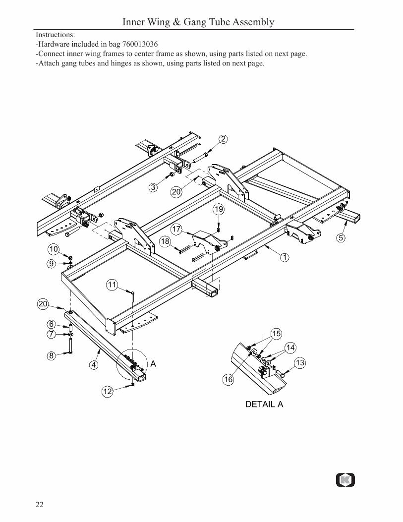
Instructions:-Hardware included in bag 760013036-Connect inner wing frames to center frame as shown, using parts listed on next page.-Attach gang tubes and hinges as shown, using parts listed on next page.
Inner Wing & Gang Tube Assembly
�
�
�
�
�
�
��
�
�
��
��
��
��
��
����
��
���������
��
��
��
��

23
Parts list / 9200 DF Inner Wing & Gang Tube Assembly. Date: April 2015 Fig. Part no. Qty Description
1 760013056 1 Inner Wing Frame Assembly, LH 760013057 1 Inner Wing Frame Assembly, RH (not shown) 2 7600355106 4 Hex Bolt, 1-1/2"-6 X 10-1/2" GR. 8 Special3 7600366053 4 Nut, Toplock 1-1/2"-64 760013063 2 Gang Tube Assembly, Inner Wing Front5 760013064 2 Gang Tube Assembly, Inner Wing Rear6 760015081 4 Bushing, Gang Pivot7 7600381056 4 Flat Washer, 1-1/4" Hardened GR. 98 7600355104 4 Hex Bolt, 1-1/4" x 10" GR. 89 7600382104 4 Lock Washer, 1-1/4"10 600365064 4 Nut, Standard 1-1/4" GR. 811 600355054 4 Hex Bolt, 1" x 6-1/2" GR. 812 7600366052 4 Flange Nut, Spiralock 1"13 600356011 8 Hex Bolt, 3/4" x 2-1/2" GR. 5 (Full Thread)14 600381009 16 Flat Washer, 3/4"15 7600365080 16 Jam Nut, 3/4"16 100401006 8 Bearing, Gang Adjust17 760016053 4 Hinge, Inner Wing18 76101277 16 Hex Bolt, 3/4"-10 X 8-1/2" GR. 519 600366024 16 Nut, Toplock 3/4"20 600471000 8 Grease Fitting (pre-installed)
24
Inner Wing Fold Cylinder Assembly
��
� �
�
��
�
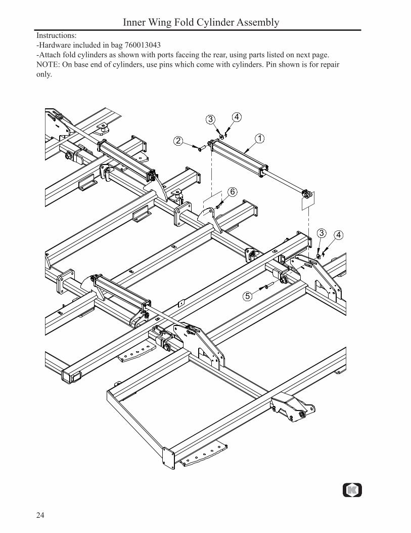
Instructions:-Hardware included in bag 760013043-Attach fold cylinders as shown with ports faceing the rear, using parts listed on next page.NOTE: On base end of cylinders, use pins which come with cylinders. Pin shown is for repair only.
25
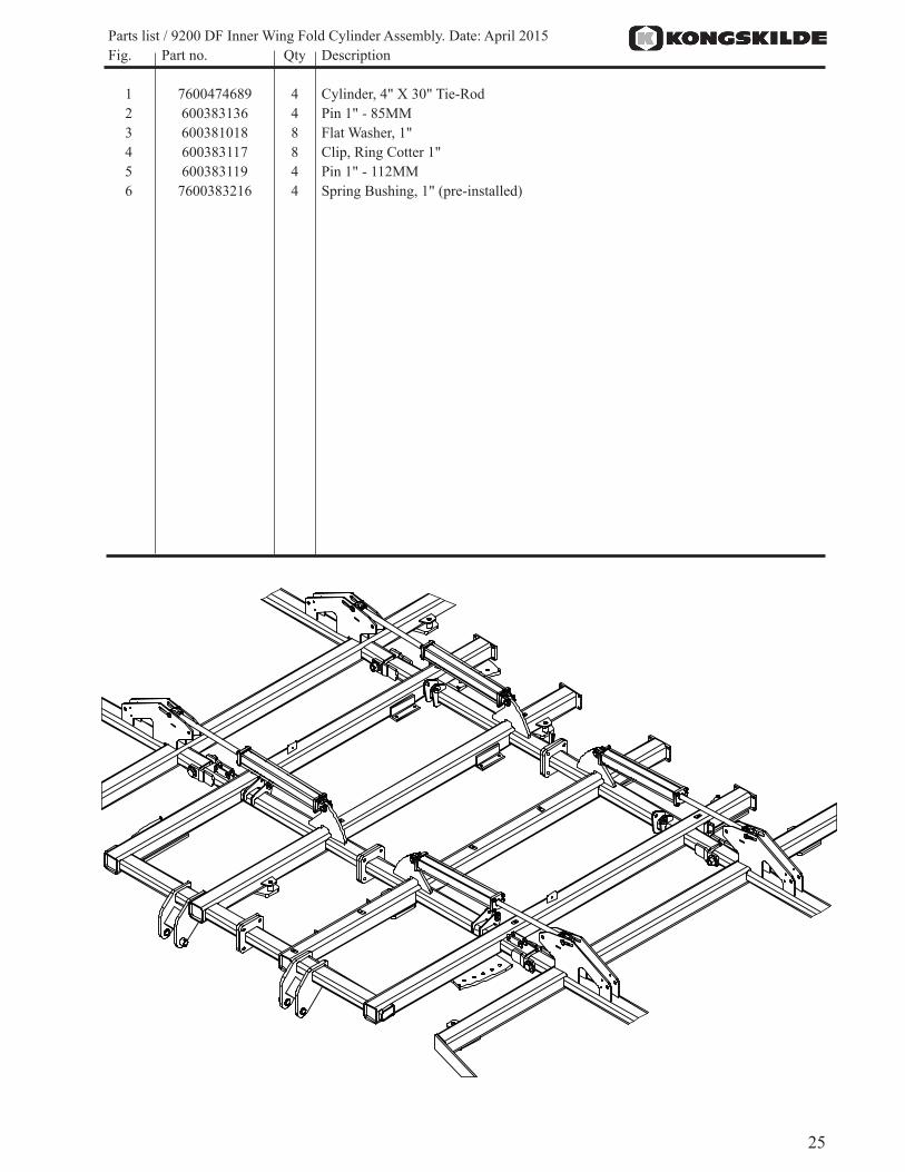
Parts list / 9200 DF Inner Wing Fold Cylinder Assembly. Date: April 2015 Fig. Part no. Qty Description
1 7600474689 4 Cylinder, 4" X 30" Tie-Rod2 600383136 4 Pin 1" - 85MM3 600381018 8 Flat Washer, 1"4 600383117 8 Clip, Ring Cotter 1"5 600383119 4 Pin 1" - 112MM6 7600383216 4 Spring Bushing, 1" (pre-installed)
26
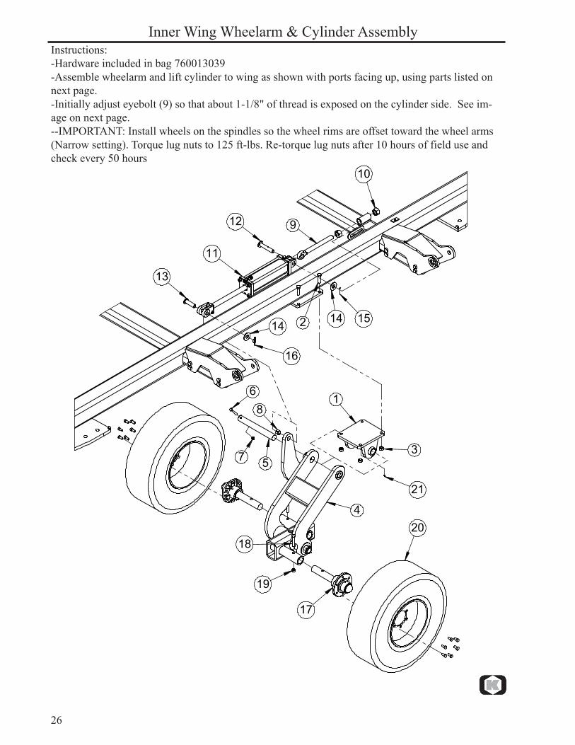
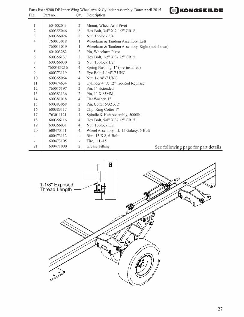
Instructions:-Hardware included in bag 760013039-Assemble wheelarm and lift cylinder to wing as shown with ports facing up, using parts listed on next page.-Initially adjust eyebolt (9) so that about 1-1/8" of thread is exposed on the cylinder side. See im-age on next page.--IMPORTANT: Install wheels on the spindles so the wheel rims are offset toward the wheel arms (Narrow setting). Torque lug nuts to 125 ft-lbs. Re-torque lug nuts after 10 hours of field use and check every 50 hours
Inner Wing Wheelarm & Cylinder Assembly
�
�
�
�
�
�
�
�
�
��
��
��
��
�� ��
��
��
��
��
��
��
��
27
Parts list / 9200 DF Inner Wing Wheelarm & Cylinder Assembly. Date: April 2015 Fig. Part no. Qty Description
1 604002043 2 Mount, Wheel Arm Pivot2 600355046 8 Hex Bolt, 3/4" X 2-1/2" GR. 83 600366024 8 Nut, Toplock 3/4"4 760013018 1 Wheelarm & Tandem Assembly, Left 760013019 1 Wheelarm & Tandem Assembly, Right (not shown) 5 604003282 2 Pin, Wheelarm Pivot6 600356137 2 Hex Bolt, 1/2" X 3-1/2" GR. 57 600366030 2 Nut, Toplock 1/2"8 7600383216 4 Spring Bushing, 1" (pre-installed) 9 600373119 2 Eye Bolt, 1-1/4"-7 UNC10 600365064 4 Nut, 1-1/4"-7 UNC11 600474634 2 Cylinder 4” X 12” Tie-Rod Rephase12 760015197 2 Pin, 1" Extended13 600383136 2 Pin, 1" X 85MM14 600381018 4 Flat Washer, 1"15 600383058 2 Pin, Cotter 5/32 X 2"16 600383117 2 Clip, Ring Cotter 1"17 763011121 4 Spindle & Hub Assembly, 5000lb18 600356116 4 Hex Bolt, 5/8" X 3-1/2" GR. 519 600366031 4 Nut, Toplock 5/8"20 600473111 4 Wheel Assembly, llL-15 Galaxy, 6-Bolt- 600473112 - Rim, 15 X 8, 6-Bolt- 600473105 - Tire, 11L-1521 600471000 2 Grease Fitting
���������������������������
See following page for part details
28
Wing Wheelarm Part Details
�
�
�
��
�
�
����
��
��
��
��
����
��
��
����
��
���� ��
��
��
����
29
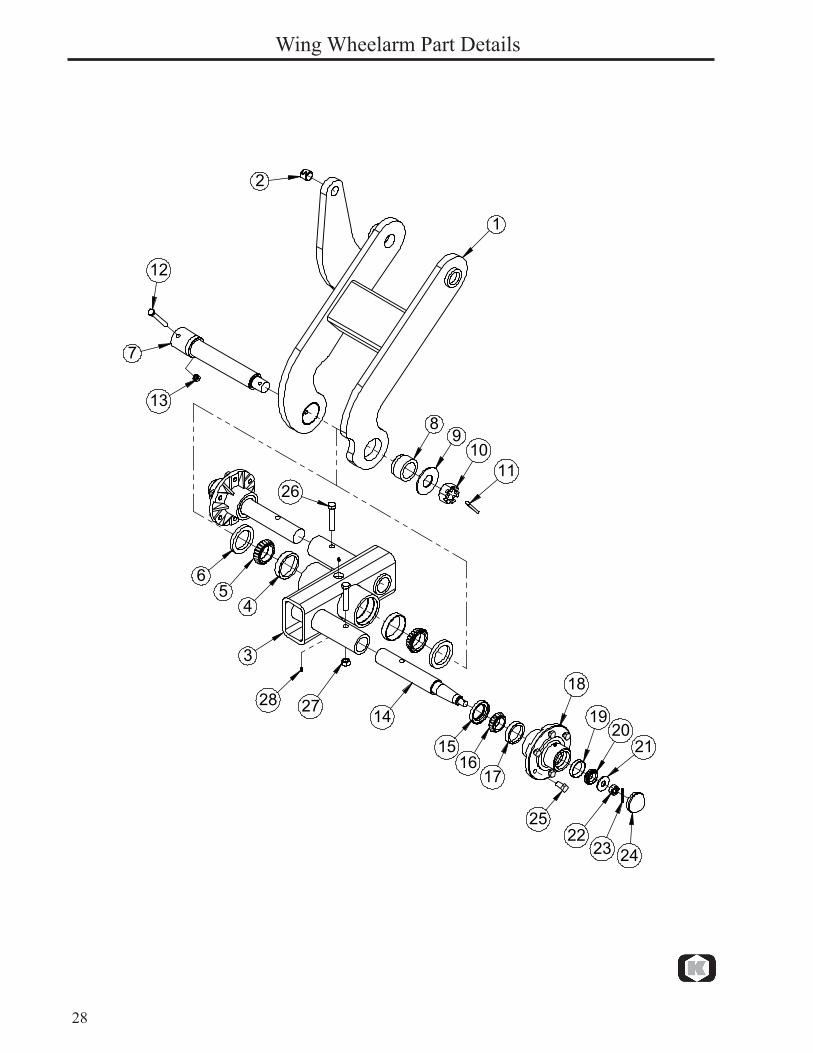
Parts list / 9200 DF Wing Wheelarm Part Details. Date: April 2015 Fig. Part no. Qty Description
1 760016024 1 Wheel Arm Wdmt, LH- 760016025 1 Wheel Arm Wdmt, RH (not shown)2 7600383216 1 1" Connex Bushing3 760016070 1 Wing Tandem Wdmt4 76301137 2 Race JLM 5068105 76301131 2 Cone LM 5068496 600473057 2 Seal, 2-3/4" w/Spring & Alternate Lip 7 604002047 1 Pin, Tandem Pivot8 604002063 1 Bushing, Tandem Pivot 9 600381054 1 Flatwasher, 1 1/2” SAE10 600366036 1 Slotted Nut, 1 1/2” - 12 UNF11 600383005 1 Pin, Cotter 5/16” x 2 1/2”12 600356105 1 Bolt, 1/2” x 4 GR. 513 600366030 1 Nut, Toplock 1/2”14 763012199 2 Spindle 5000lb- 763012198 - Spindle Assembly Complete (Includes Items 14, 21, 22, 23 )15 7600473135 2 Seal, 2" w/Spring & Alternate Lip16 76301129 2 Cone LM 50134917 76301135 2 Race LM 50131018 763011269 2 Hub 5000lb (Includes Items 17, 18, 19, 25, 28)- 763011609 - Hub 5000lb, Complete (Includes Items 15, 16, 18, 20, 24)- 760013002 - Kit, 6-Bolt Hub Bearing (Includes Items 15, 16, 17, 19, 20, 21, 22, 23, 24)19 76301134 2 Race LM 6701020 76301132 2 Cone LM 6704821 76301157 2 Flatwasher, 2" OD x 13/16" ID22 76301153 2 Slotted Nut, 3/4” - 16 UNF23 76101249 2 Pin, Cotter 5/32” x 1 3/4”24 76301143 2 Dust Cap25 76301151 12 Lug Bolt, 9/16”-1826 600356116 2 Bolt, 5/8” x 3 1/2” GR. 527 600366031 2 Nut, Toplock 5/8”28 600471000 3 Grease Fitting
Quantities listed are for one completewing wheelarm & tandem ssembly

30
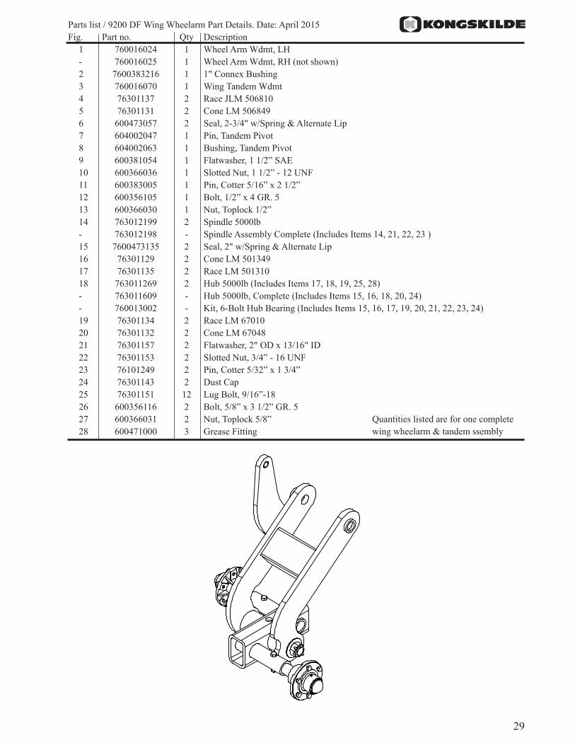
Instructions:-Hardware included in bags 760013045, 760013046, 760013047-Attach bearing towers (2 & 3), c-springs (4), and scraper bracket (5) to gang assemblies using hard-ware listed on next page. Torque bolts (6) to 300 ft-lbs. NOTE: Rotate gang bearing so grease fit-ting is facing rearwards.-Attach gang & c-sping assembly to gang tubes using clamp plates and bolts shown. See Appendix C (pg 60) for gang layout details.-Install scraper tubes and scrapers after gangs have been mounted to machine. NOTE: Offset scrap-ers should be mounted as close as possible (without touching) to the concave side of the blades .
Inner Wing Gang & Scraper Assembly
��
��
�
�
��
�
�
��
��
��
��
���
����
��
���
��
��
Image for reference only
31
Parts list / 9200 DF Inner Wing Gang & Scraper Assembly. Date: April 2015 Fig. Part no. Qty Description
1 760013027 2 Gang Assembly, 12-Blade Inner Wing Front - not shown- 760013028 2 Gang Assembly, 12-Blade Inner Wing Rear - not shown 2 604002087 12 Tower, Gang Bearing3a 760012000 6 Tower, Gang Bearing Scraper LH (Included in HD Scraper Option)- 760012001 6 Tower, Gang Bearing Scraper RH (Included in HD Scraper Option) - not shown3b 604002087 12 Tower, Gang Bearing (Included in Offset Scraper Option)4 604002040 12 C-Spring5 760012002 12 Scraper Bracket 6 600355001 24 Hex Bolt, 3/4" X 3" GR. 87 600382055 24 Lock Washer, 3/4"8 604002067 24 Plate, Gang Mount9 600355067 36 Hex Bolt, 3/4" X 7-1/2" GR. 810 600366024 36 Nut, Toplock 3/4"11 604002190 4 Scraper Tube, 12-Blade (75")12 600373112 12 U-Bolt, 5/8" X 2" X 3-1/2"13 600366031 24 Nut, Toplock 5/8"14a 760012019 36 HD Scraper Wdmt (Included in HD Scraper Option)14b 760015198 36 Offset Scraper (Included in Offset Scraper Option)15 600373061 36 U-Bolt, 1/2" X 2" X 3-1/4"16 600366030 72 Nut, Toplock 1/2"
See pages 20 & 21 for gang details

32
Instructions:-Hardware included in bag 760013037-Connect outer wing frames to inner frames as shown, using parts listed on next page.-Attach gang tubes as shown, using parts listed on next page.
Outer Wing & Gang Tube Assembly
�
�
�
�
�
�
�
�
�
�
��
��
��
��
��
��������
��
����
��

33
Parts list / 9200 DF Outer Wing & Gang Tube Assembly. Date: April 2015 Fig. Part no. Qty Description
1 760013058 1 Outer Wing Frame Assembly, LH 760013059 1 Outer Wing Frame Assembly, RH (not shown) 2 7600355107 4 Hex Bolt, 1-1/4"-7 X 9" GR. 8 Special3 600366033 4 Nut, Toplock 1-1/4"-74 760013065 2 Gang Tube Assembly, Outer Wing Front5 760013066 2 Gang Tube Assembly, Outer Wing Rear6 760015081 4 Bushing, Gang Pivot7 7600381056 4 Flat Washer, 1-1/4" Hardened GR. 98 7600355104 4 Hex Bolt, 1-1/4" x 10" GR. 89 7600382104 4 Lock Washer, 1-1/4"10 600365064 4 Nut, Standard 1-1/4" GR. 811 600355054 4 Hex Bolt, 1" x 6-1/2" GR. 812 7600366052 4 Flange Nut, Spiralock 1"13 600356011 8 Hex Bolt, 3/4" x 2-1/2" GR. 5 (Full Thread)14 600381009 16 Flat Washer, 3/4"15 7600365080 16 Jam Nut, 3/4"16 100401006 8 Bearing, Gang Adjust17 600471000 8 Grease Fitting (pre-installed)
34
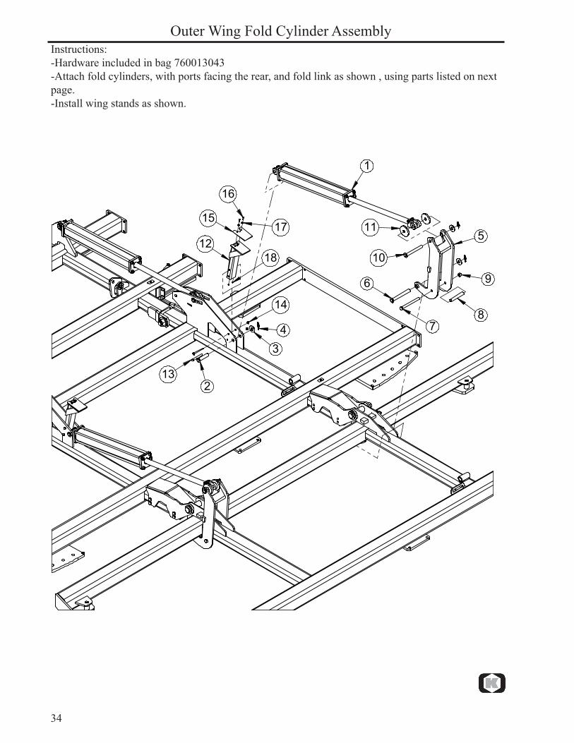
Outer Wing Fold Cylinder AssemblyInstructions:-Hardware included in bag 760013043-Attach fold cylinders, with ports facing the rear, and fold link as shown , using parts listed on next page.-Install wing stands as shown.
�
�
��
�
�
��
�
��
����
��
��
��
��
��
��
35
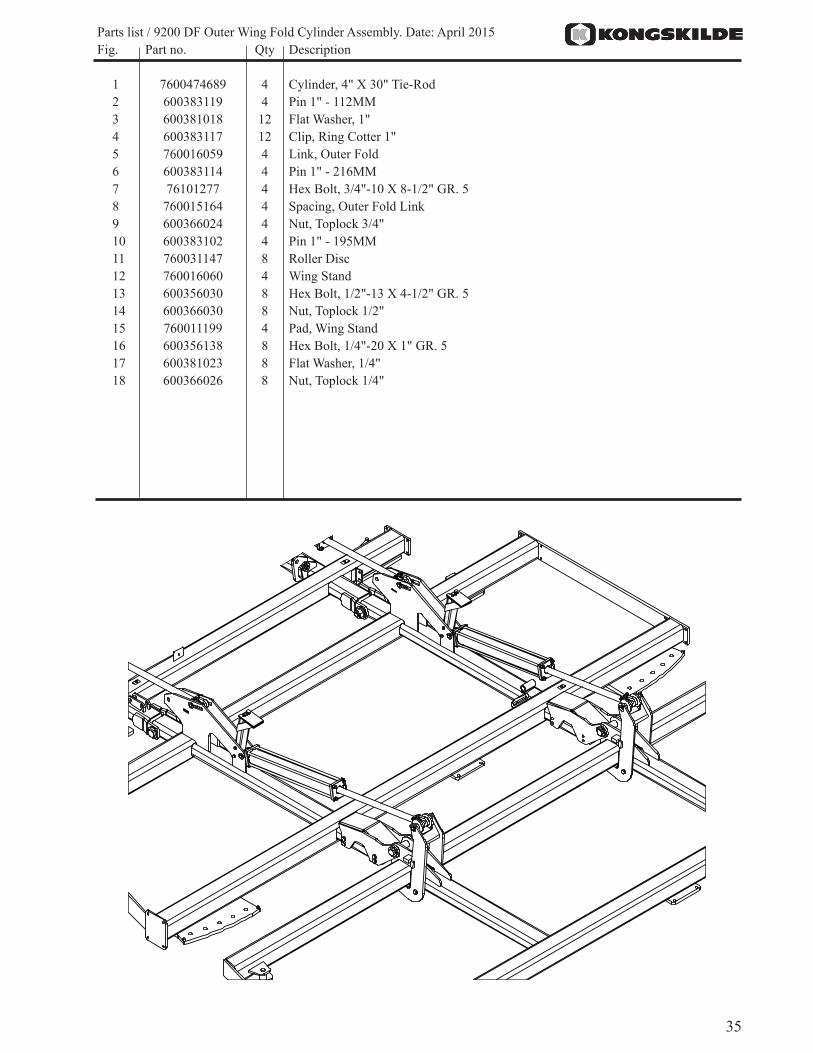
Parts list / 9200 DF Outer Wing Fold Cylinder Assembly. Date: April 2015 Fig. Part no. Qty Description
1 7600474689 4 Cylinder, 4" X 30" Tie-Rod2 600383119 4 Pin 1" - 112MM3 600381018 12 Flat Washer, 1"4 600383117 12 Clip, Ring Cotter 1"5 760016059 4 Link, Outer Fold6 600383114 4 Pin 1" - 216MM7 76101277 4 Hex Bolt, 3/4"-10 X 8-1/2" GR. 58 760015164 4 Spacing, Outer Fold Link9 600366024 4 Nut, Toplock 3/4"10 600383102 4 Pin 1" - 195MM11 760031147 8 Roller Disc12 760016060 4 Wing Stand13 600356030 8 Hex Bolt, 1/2"-13 X 4-1/2" GR. 514 600366030 8 Nut, Toplock 1/2"15 760011199 4 Pad, Wing Stand16 600356138 8 Hex Bolt, 1/4"-20 X 1" GR. 517 600381023 8 Flat Washer, 1/4"18 600366026 8 Nut, Toplock 1/4"
36
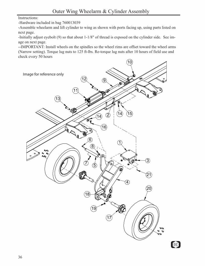
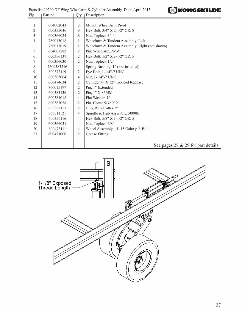
Instructions:-Hardware included in bag 760013039-Assemble wheelarm and lift cylinder to wing as shown with ports facing up, using parts listed on next page.-Initially adjust eyebolt (9) so that about 1-1/8" of thread is exposed on the cylinder side. See im-age on next page.--IMPORTANT: Install wheels on the spindles so the wheel rims are offset toward the wheel arms (Narrow setting). Torque lug nuts to 125 ft-lbs. Re-torque lug nuts after 10 hours of field use and check every 50 hours
Outer Wing Wheelarm & Cylinder Assembly
�
�
�
�
�
�
�
�
�
��
��
��
��
�� ��
��
��
��
��
��
��
��
Image for reference only
37
Parts list / 9200 DF Wing Wheelarm & Cylinder Assembly. Date: April 2015 Fig. Part no. Qty Description
1 604002043 2 Mount, Wheel Arm Pivot2 600355046 8 Hex Bolt, 3/4" X 2-1/2" GR. 83 600366024 8 Nut, Toplock 3/4"4 760013018 1 Wheelarm & Tandem Assembly, Left 760013019 1 Wheelarm & Tandem Assembly, Right (not shown) 5 604003282 2 Pin, Wheelarm Pivot6 600356137 2 Hex Bolt, 1/2" X 3-1/2" GR. 57 600366030 2 Nut, Toplock 1/2"8 7600383216 4 Spring Bushing, 1" (pre-installed) 9 600373119 2 Eye Bolt, 1-1/4"-7 UNC10 600365064 4 Nut, 1-1/4"-7 UNC11 600474634 2 Cylinder 4” X 12” Tie-Rod Rephase12 760015197 2 Pin, 1" Extended13 600383136 2 Pin, 1" X 85MM14 600381018 4 Flat Washer, 1"15 600383058 2 Pin, Cotter 5/32 X 2"16 600383117 2 Clip, Ring Cotter 1"17 763011121 4 Spindle & Hub Assembly, 5000lb18 600356116 4 Hex Bolt, 5/8" X 3-1/2" GR. 519 600366031 4 Nut, Toplock 5/8"20 600473111 4 Wheel Assembly, llL-15 Galaxy, 6-Bolt21 600471000 2 Grease Fitting
���������������������������
See pages 28 & 29 for part details
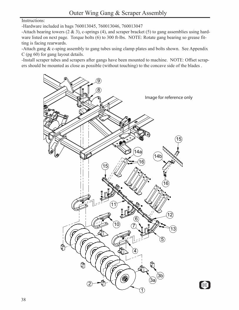
38
Instructions:-Hardware included in bags 760013045, 760013046, 760013047-Attach bearing towers (2 & 3), c-springs (4), and scraper bracket (5) to gang assemblies using hard-ware listed on next page. Torque bolts (6) to 300 ft-lbs. NOTE: Rotate gang bearing so grease fit-ting is facing rearwards.-Attach gang & c-sping assembly to gang tubes using clamp plates and bolts shown. See Appendix C (pg 60) for gang layout details.-Install scraper tubes and scrapers after gangs have been mounted to machine. NOTE: Offset scrap-ers should be mounted as close as possible (without touching) to the concave side of the blades .
Outer Wing Gang & Scraper Assembly
��
��
�
�
��
�
�
��
��
��
��
���
����
��
���
��
��
Image for reference only
39
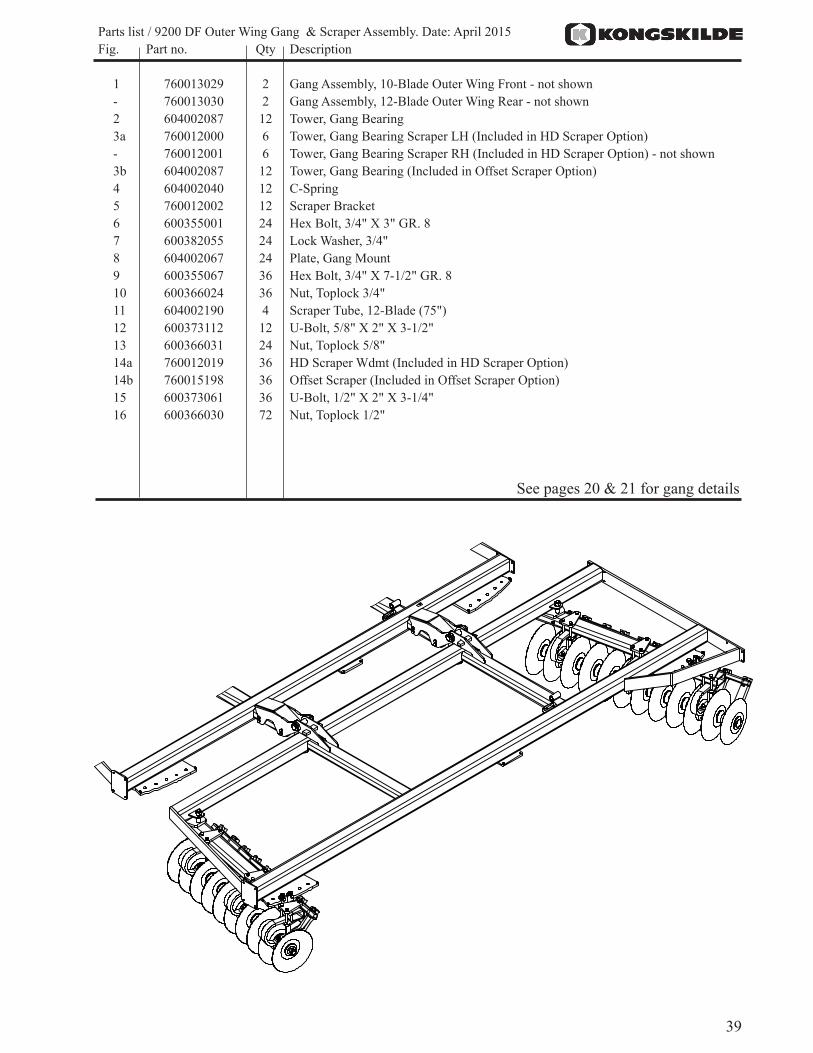
See pages 20 & 21 for gang details
Parts list / 9200 DF Outer Wing Gang & Scraper Assembly. Date: April 2015 Fig. Part no. Qty Description
1 760013029 2 Gang Assembly, 10-Blade Outer Wing Front - not shown- 760013030 2 Gang Assembly, 12-Blade Outer Wing Rear - not shown 2 604002087 12 Tower, Gang Bearing3a 760012000 6 Tower, Gang Bearing Scraper LH (Included in HD Scraper Option)- 760012001 6 Tower, Gang Bearing Scraper RH (Included in HD Scraper Option) - not shown3b 604002087 12 Tower, Gang Bearing (Included in Offset Scraper Option)4 604002040 12 C-Spring5 760012002 12 Scraper Bracket 6 600355001 24 Hex Bolt, 3/4" X 3" GR. 87 600382055 24 Lock Washer, 3/4"8 604002067 24 Plate, Gang Mount9 600355067 36 Hex Bolt, 3/4" X 7-1/2" GR. 810 600366024 36 Nut, Toplock 3/4"11 604002190 4 Scraper Tube, 12-Blade (75")12 600373112 12 U-Bolt, 5/8" X 2" X 3-1/2"13 600366031 24 Nut, Toplock 5/8"14a 760012019 36 HD Scraper Wdmt (Included in HD Scraper Option)14b 760015198 36 Offset Scraper (Included in Offset Scraper Option)15 600373061 36 U-Bolt, 1/2" X 2" X 3-1/4"16 600366030 72 Nut, Toplock 1/2"
40
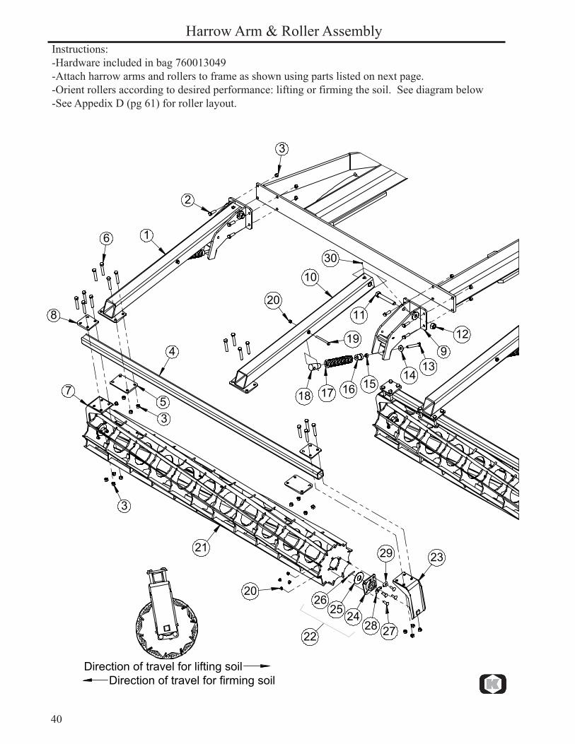
Instructions:-Hardware included in bag 760013049-Attach harrow arms and rollers to frame as shown using parts listed on next page.-Orient rollers according to desired performance: lifting or firming the soil. See diagram below-See Appedix D (pg 61) for roller layout.
Harrow Arm & Roller Assembly
�
�
�
�
�
�
�
�
�
��
����
����
��������
��
��
����
������
����
��
��
��
�
�
��
������������������������������������������������������������������������
41
Parts list / 9200 DF Harrow Arm & Roller Assembly. Date: April 2015 Fig. Part no. Qty Description
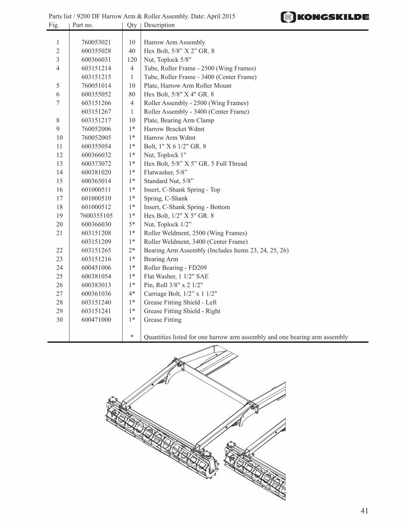
1 760053021 10 Harrow Arm Assembly2 600355028 40 Hex Bolt, 5/8” X 2” GR. 83 600366031 120 Nut, Toplock 5/8"4 603151214 4 Tube, Roller Frame - 2500 (Wing Frames) 603151215 1 Tube, Roller Frame - 3400 (Center Frame)5 760051014 10 Plate, Harrow Arm Roller Mount6 600355052 80 Hex Bolt, 5/8" X 4" GR. 87 603151266 4 Roller Assembly - 2500 (Wing Frames) 603151267 1 Roller Assembly - 3400 (Center Frame)8 603151217 10 Plate, Bearing Arm Clamp9 760052006 1* Harrow Bracket Wdmt10 760052005 1* Harrow Arm Wdmt11 600355054 1* Bolt, 1" X 6 1/2" GR. 812 600366032 1* Nut, Toplock 1"13 600373072 1* Hex Bolt, 5/8” X 5” GR. 5 Full Thread14 600381020 1* Flatwasher, 5/8”15 600365014 1* Standard Nut, 5/8”16 601000511 1* Insert, C-Shank Spring - Top17 601000510 1* Spring, C-Shank18 601000512 1* Insert, C-Shank Spring - Bottom19 7600355105 1* Hex Bolt, 1/2" X 5" GR. 820 600366030 5* Nut, Toplock 1/2”21 603151208 1* Roller Weldment, 2500 (Wing Frames) 603151209 1* Roller Weldment, 3400 (Center Frame)22 603151265 2* Bearing Arm Assembly (Includes Items 23, 24, 25, 26)23 603151216 1* Bearing Arm24 600451006 1* Roller Bearing - FD20925 600381054 1* Flat Washer, 1 1/2" SAE26 600383013 1* Pin, Roll 3/8" x 2 1/2"27 600361036 4* Carriage Bolt, 1/2” x 1 1/2"28 603151240 1* Grease Fitting Shield - Left29 603151241 1* Grease Fitting Shield - Right30 600471000 1* Grease Fitting
* Quantities listed for one harrow arm assembly and one bearing arm assembly
42
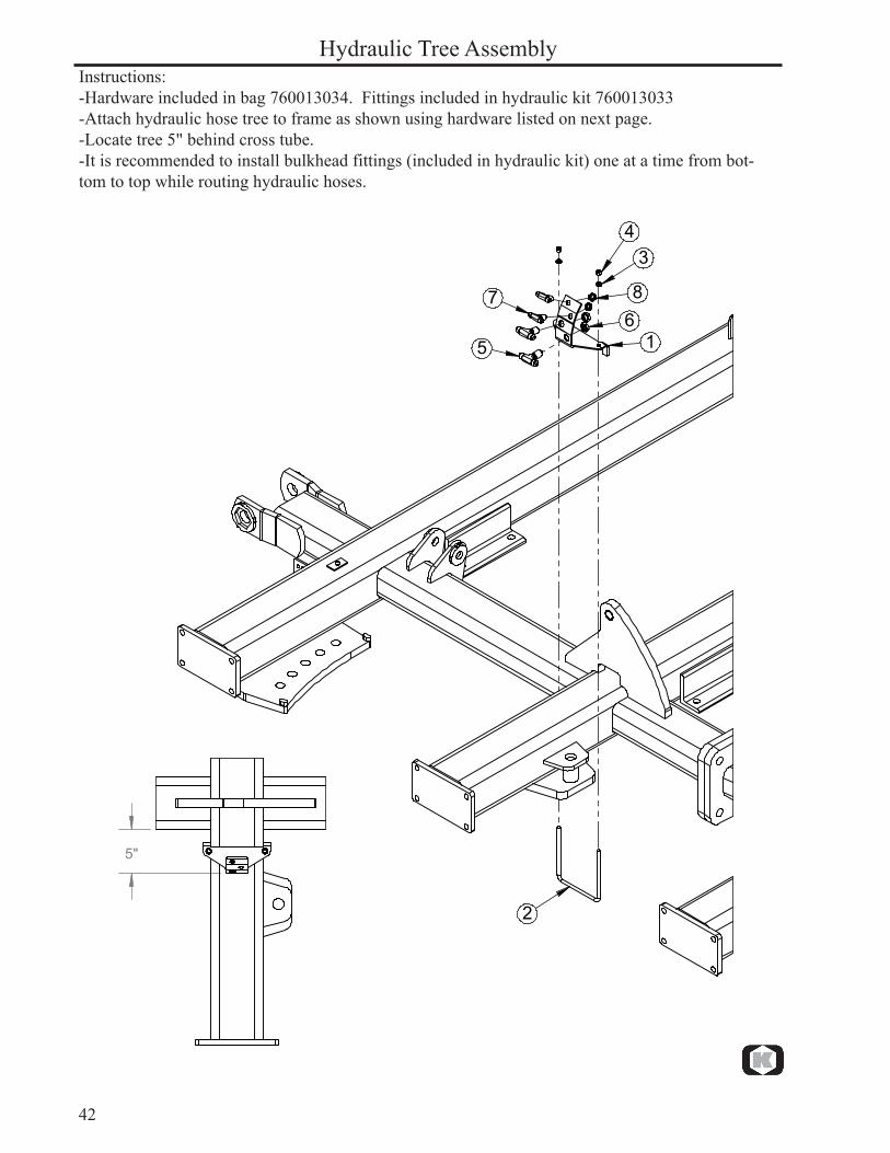
Hydraulic Tree AssemblyInstructions:-Hardware included in bag 760013034. Fittings included in hydraulic kit 760013033-Attach hydraulic hose tree to frame as shown using hardware listed on next page.-Locate tree 5" behind cross tube.-It is recommended to install bulkhead fittings (included in hydraulic kit) one at a time from bot-tom to top while routing hydraulic hoses.
�
�
��
��
� �
����
43
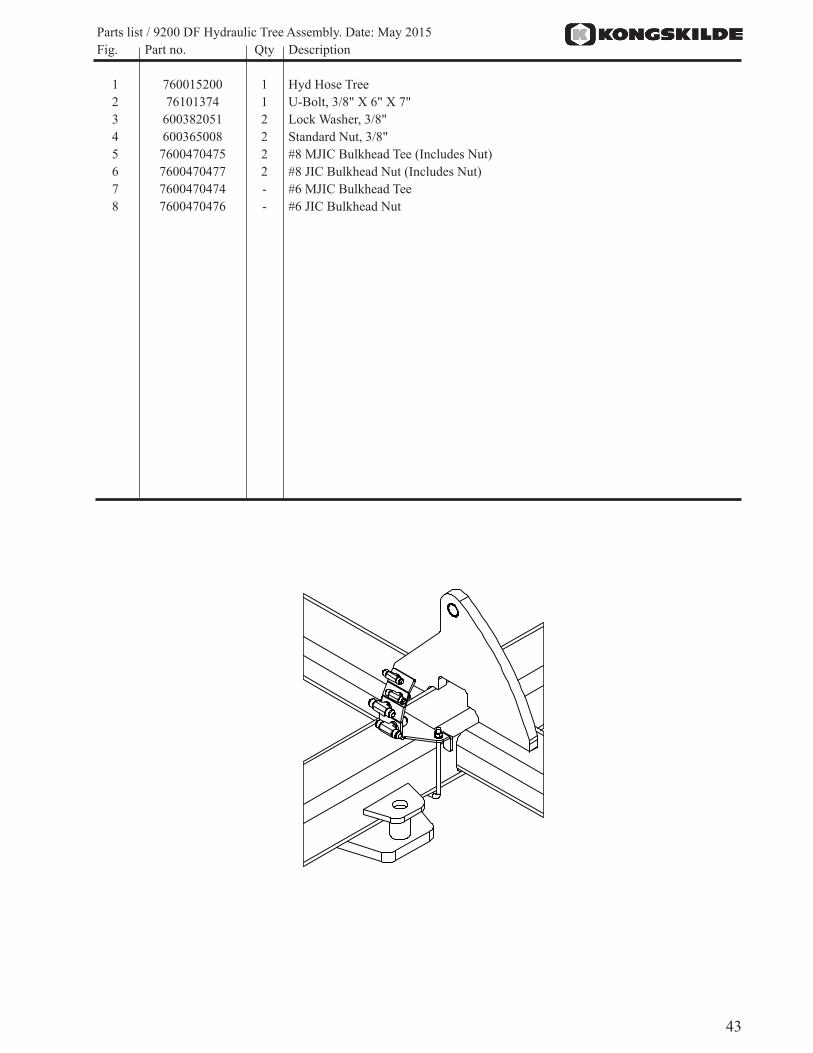
Parts list / 9200 DF Hydraulic Tree Assembly. Date: May 2015 Fig. Part no. Qty Description
1 760015200 1 Hyd Hose Tree2 76101374 1 U-Bolt, 3/8" X 6" X 7" 3 600382051 2 Lock Washer, 3/8"4 600365008 2 Standard Nut, 3/8"5 7600470475 2 #8 MJIC Bulkhead Tee (Includes Nut)6 7600470477 2 #8 JIC Bulkhead Nut (Includes Nut)7 7600470474 - #6 MJIC Bulkhead Tee 8 7600470476 - #6 JIC Bulkhead Nut
44
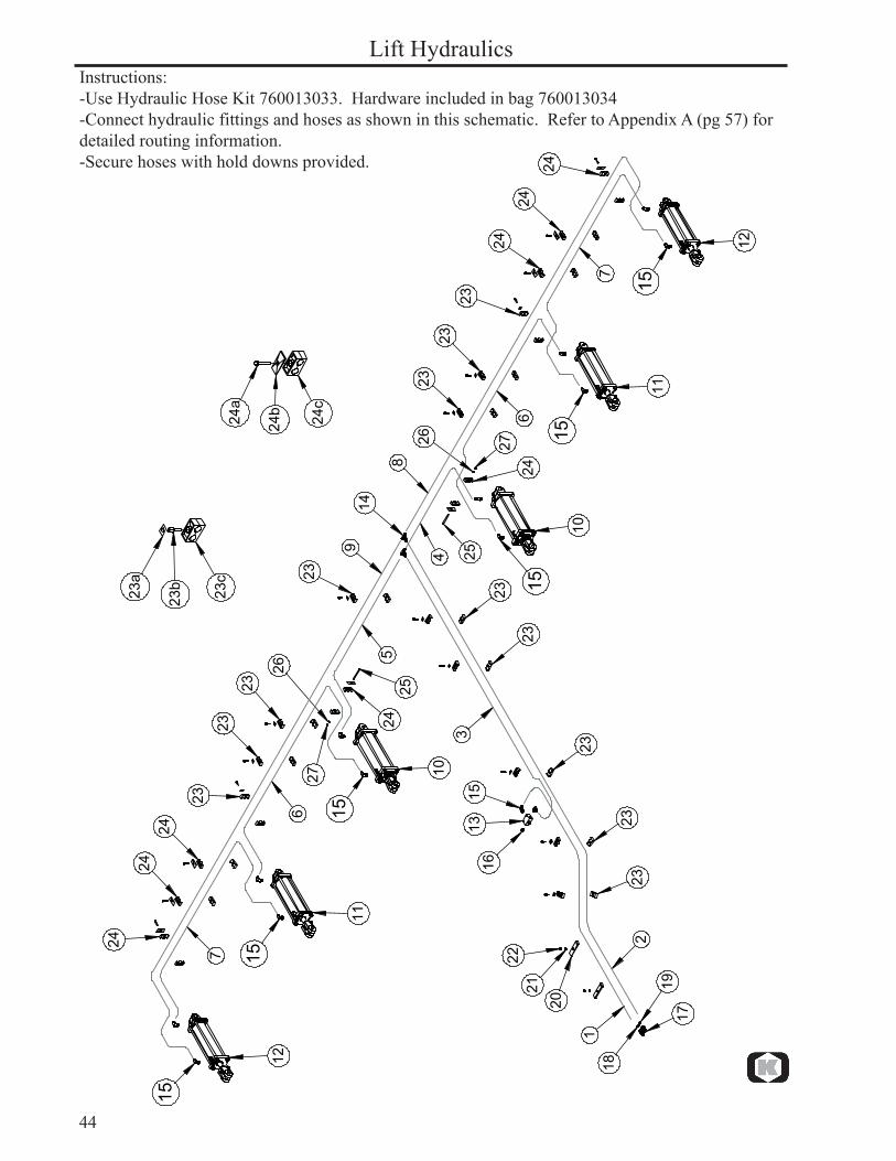
Lift HydraulicsInstructions:-Use Hydraulic Hose Kit 760013033. Hardware included in bag 760013034-Connect hydraulic fittings and hoses as shown in this schematic. Refer to Appendix A (pg 57) for detailed routing information.-Secure hoses with hold downs provided.
1
2
34
5
6
6
7
7
8
9
10
10
11
11
12
12
13
14
1516
17
18
19
2021
22
2323
23
23
23
2323
23
2323
23
24
24
2424
2424
24
23
25
25
26
26 27
27
24
15
15
15
15
1515
24a
24b 24c
23a
23b 23c
45
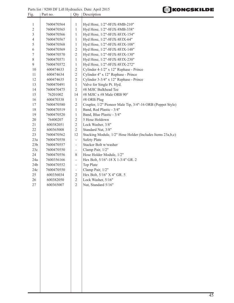
Parts list / 9200 DF Lift Hydraulics. Date: April 2015 Fig. Part no. Qty Description
1 7600470564 1 Hyd Hose, 1/2"-8FJX-8MB-210"2 7600470565 1 Hyd Hose, 1/2"-8FJX-8MB-338"3 7600470566 1 Hyd Hose, 1/2"-8FJX-8FJX-154"4 7600470567 1 Hyd Hose, 1/2"-8FJX-8FJX-64"5 7600470568 1 Hyd Hose, 1/2"-8FJX-8FJX-108"6 7600470569 2 Hyd Hose, 1/2"-8FJX-8FJX-148"7 7600470570 2 Hyd Hose, 1/2"-8FJX-8FJX-130"8 7600470571 1 Hyd Hose, 1/2"-8FJX-8FJX-230"9 7600470572 1 Hyd Hose, 1/2"-8FJX-8FJX-272"10 600474633 2 Cylinder 4-1/2" x 12" Rephase - Prince11 600474634 2 Cylinder 4" x 12" Rephase - Prince12 600474635 2 Cylinder 3-3/4" x 12" Rephase - Prince13 7600470491 1 Valve for Single Pt. Hyd.14 7600470475 2 #8 MJIC Bulkhead Tee15 76201002 14 #8 MJIC x #8 Male ORB 90°16 600470338 1 #8 ORB Plug17 7600470580 2 Coupler, 1/2" Pioneer Male Tip, 3/4"-16 ORB (Poppet Style)18 7600470519 1 Band, Red Plastic - 3/4"19 7600470520 1 Band, Blue Plastic - 3/4"20 76400207 2 5 Hose Holdown21 600382051 2 Lock Washer, 3/8"22 600365008 2 Standard Nut, 3/8"23 7600470562 12 Stacking Module, 1/2" Hose Holder (Includes Items 23a,b,c)23a 7600470558 - Safety Plate23b 7600470557 - Stacker Bolt w/washer23c 7600470550 - Clamp Pair, 1/2"24 7600470556 8 Hose Holder Module, 1/2"24a 7600356166 - Hex Bolt, 5/16"-18 X 1-3/4" GR. 224b 7600470552 - Top Plate24c 7600470550 - Clamp Pair, 1/2"25 600356034 2 Hex Bolt, 5/16" X 4" GR. 526 600382050 2 Lock Washer, 5/16"27 600365007 2 Nut, Standard 5/16"
46
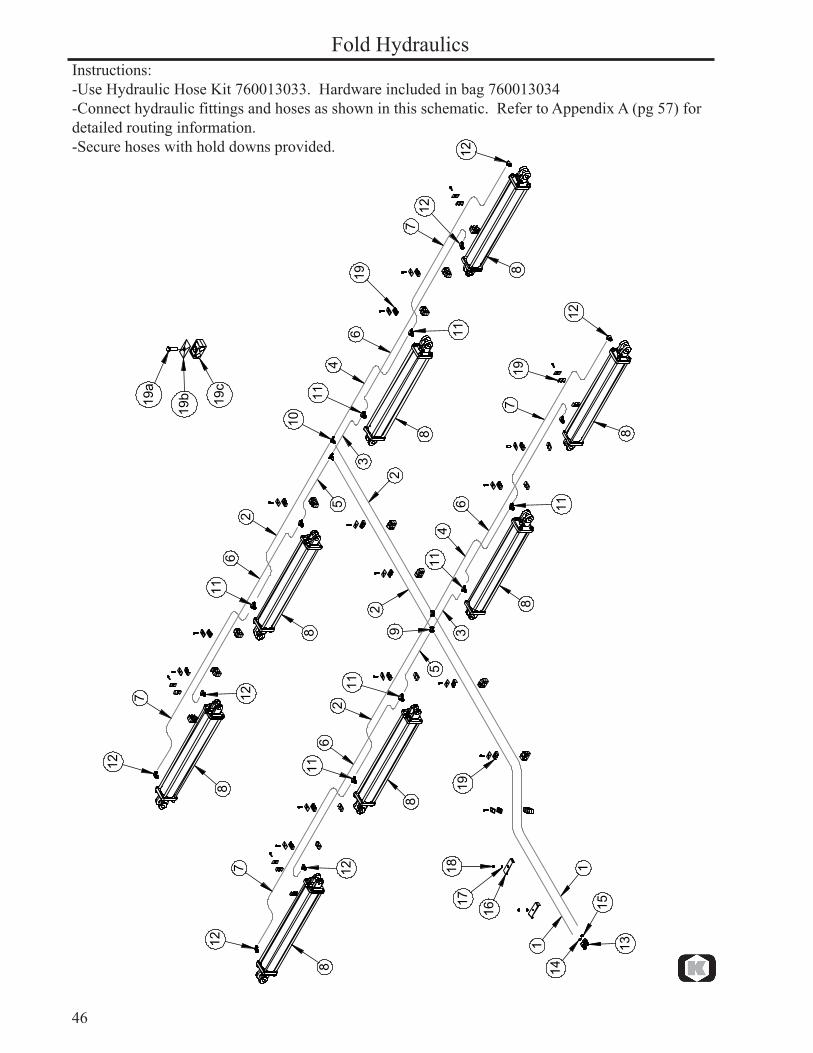
Fold HydraulicsInstructions:-Use Hydraulic Hose Kit 760013033. Hardware included in bag 760013034-Connect hydraulic fittings and hoses as shown in this schematic. Refer to Appendix A (pg 57) for detailed routing information.-Secure hoses with hold downs provided.
1
1
22
3
5
3
5
6
6
4
2
2
46
7
7
6
7
7
8
8
8
8
8
8
9
10
11
11
11
11
11
11
1112
12
12
12
12
12
13
16
1718
19
19
19
14
15
8
8
12
19a
19b 19c
47
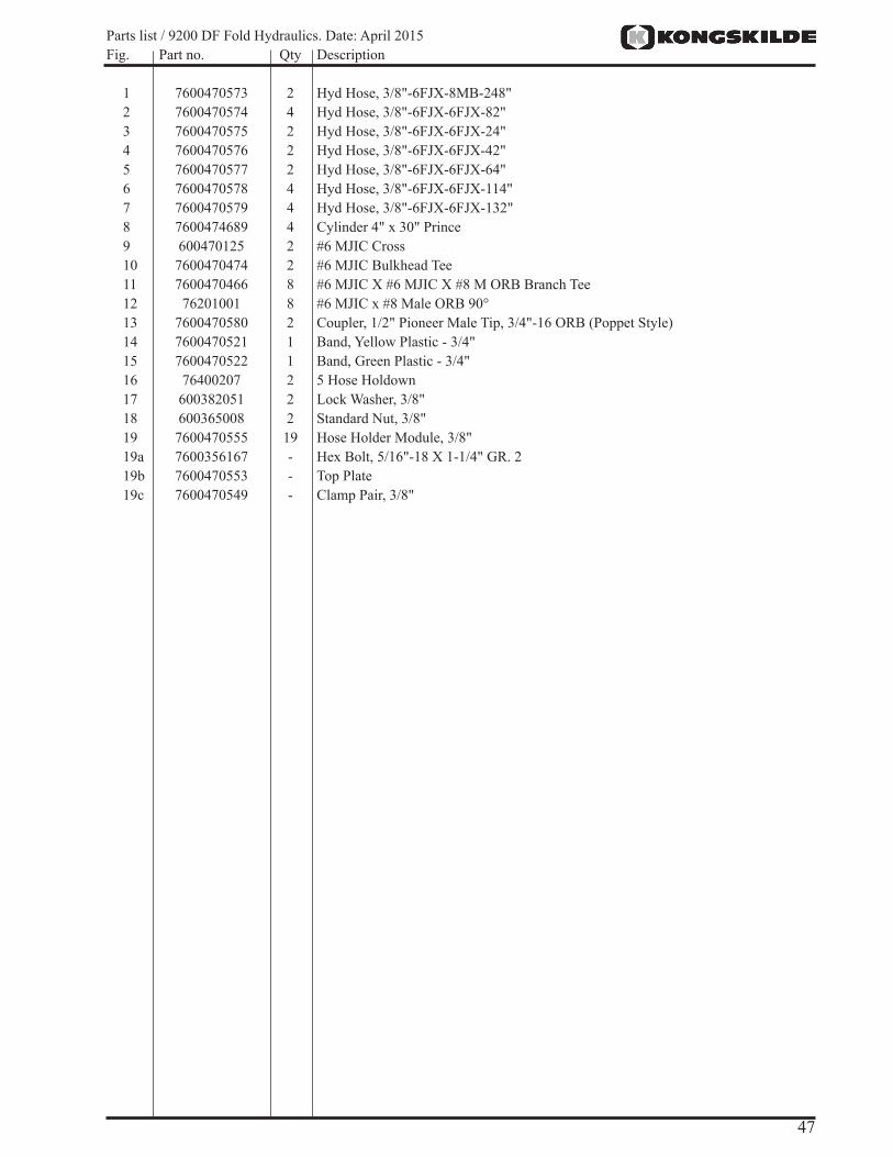
Parts list / 9200 DF Fold Hydraulics. Date: April 2015 Fig. Part no. Qty Description
1 7600470573 2 Hyd Hose, 3/8"-6FJX-8MB-248"2 7600470574 4 Hyd Hose, 3/8"-6FJX-6FJX-82"3 7600470575 2 Hyd Hose, 3/8"-6FJX-6FJX-24"4 7600470576 2 Hyd Hose, 3/8"-6FJX-6FJX-42"5 7600470577 2 Hyd Hose, 3/8"-6FJX-6FJX-64"6 7600470578 4 Hyd Hose, 3/8"-6FJX-6FJX-114"7 7600470579 4 Hyd Hose, 3/8"-6FJX-6FJX-132"8 7600474689 4 Cylinder 4" x 30" Prince 9 600470125 2 #6 MJIC Cross 10 7600470474 2 #6 MJIC Bulkhead Tee11 7600470466 8 #6 MJIC X #6 MJIC X #8 M ORB Branch Tee12 76201001 8 #6 MJIC x #8 Male ORB 90°13 7600470580 2 Coupler, 1/2" Pioneer Male Tip, 3/4"-16 ORB (Poppet Style)14 7600470521 1 Band, Yellow Plastic - 3/4"15 7600470522 1 Band, Green Plastic - 3/4"16 76400207 2 5 Hose Holdown17 600382051 2 Lock Washer, 3/8"18 600365008 2 Standard Nut, 3/8"19 7600470555 19 Hose Holder Module, 3/8"19a 7600356167 - Hex Bolt, 5/16"-18 X 1-1/4" GR. 219b 7600470553 - Top Plate19c 7600470549 - Clamp Pair, 3/8"

48
Cylinder Parts
Lift Cylinder
Fold Cylinder
� �
�
�
�
�
�
�
�
�
�
�
49
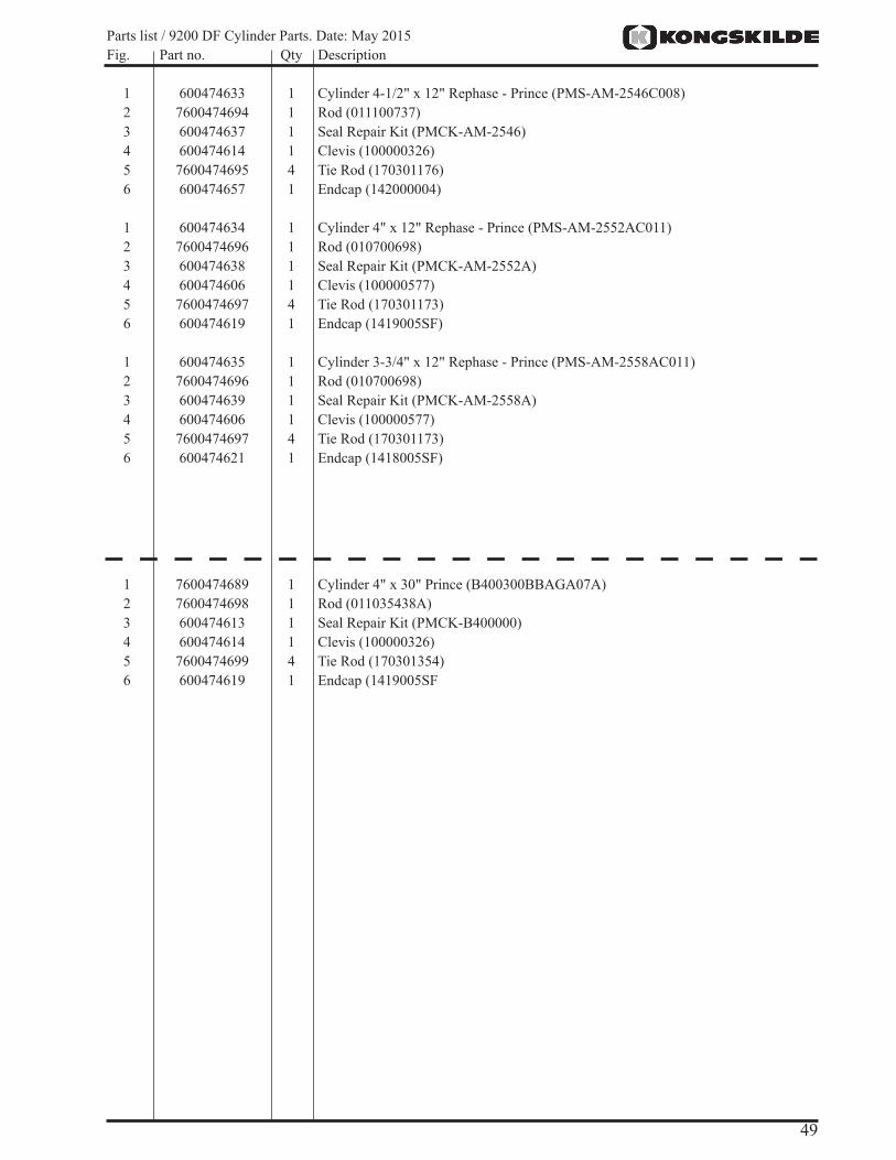
Parts list / 9200 DF Cylinder Parts. Date: May 2015 Fig. Part no. Qty Description
1 600474633 1 Cylinder 4-1/2" x 12" Rephase - Prince (PMS-AM-2546C008)2 7600474694 1 Rod (011100737)3 600474637 1 Seal Repair Kit (PMCK-AM-2546)4 600474614 1 Clevis (100000326)5 7600474695 4 Tie Rod (170301176)6 600474657 1 Endcap (142000004)
1 600474634 1 Cylinder 4" x 12" Rephase - Prince (PMS-AM-2552AC011)2 7600474696 1 Rod (010700698)3 600474638 1 Seal Repair Kit (PMCK-AM-2552A)4 600474606 1 Clevis (100000577)5 7600474697 4 Tie Rod (170301173)6 600474619 1 Endcap (1419005SF)
1 600474635 1 Cylinder 3-3/4" x 12" Rephase - Prince (PMS-AM-2558AC011)2 7600474696 1 Rod (010700698)3 600474639 1 Seal Repair Kit (PMCK-AM-2558A)4 600474606 1 Clevis (100000577)5 7600474697 4 Tie Rod (170301173)6 600474621 1 Endcap (1418005SF)
1 7600474689 1 Cylinder 4" x 30" Prince (B400300BBAGA07A)2 7600474698 1 Rod (011035438A)3 600474613 1 Seal Repair Kit (PMCK-B400000)4 600474614 1 Clevis (100000326)5 7600474699 4 Tie Rod (170301354)6 600474619 1 Endcap (1419005SF

50
Instructions:-Connect electrical wiring from light kit as shown in the schematic below. Refer to Appendix B (pg 59) for detailed routing information.-Secure wiring with cable ties.
Light Kit Assembly
2-Pin Connector
2-Pin Connector
3-Pin Connector
3-Pin Connector
4-Pin Connector
4-Pin Connector
1
2
3
4
4
5
5
51
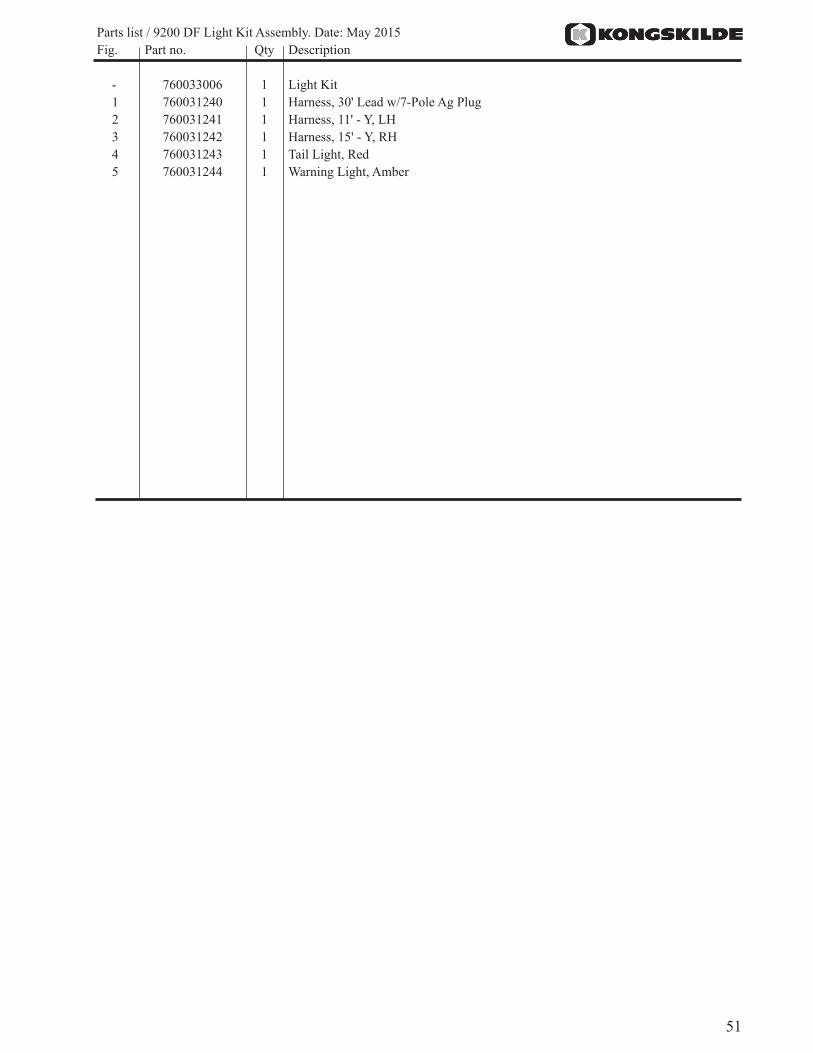
Parts list / 9200 DF Light Kit Assembly. Date: May 2015 Fig. Part no. Qty Description
- 760033006 1 Light Kit1 760031240 1 Harness, 30' Lead w/7-Pole Ag Plug2 760031241 1 Harness, 11' - Y, LH3 760031242 1 Harness, 15' - Y, RH4 760031243 1 Tail Light, Red5 760031244 1 Warning Light, Amber
52
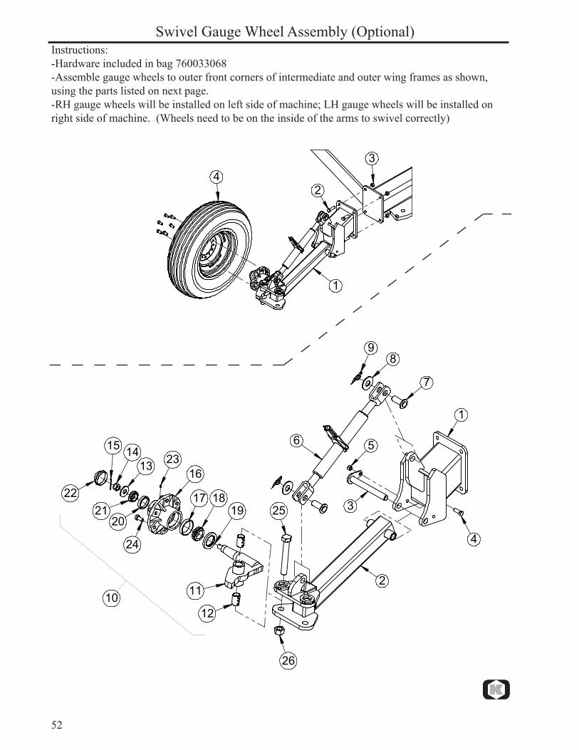
Instructions:-Hardware included in bag 760033068-Assemble gauge wheels to outer front corners of intermediate and outer wing frames as shown, using the parts listed on next page.-RH gauge wheels will be installed on left side of machine; LH gauge wheels will be installed on right side of machine. (Wheels need to be on the inside of the arms to swivel correctly)
Swivel Gauge Wheel Assembly (Optional)
�
�
��
�
�
�
�
��
�
��
��
������
��
�� ����
����
��
��
��
��
��
����
53
Parts list / 9200 DF Swivel Gauge Wheel Assembly. Date: May 2015 Fig. Part no. Qty Description
1 760033066 2 Swivel Gauge Wheel Assembly, RH 760033067 2 Swivel Gauge Wheel Assembly, LH (not shown)2 600356010 4* Hex Bolt, 5/8" X 2" GR. 53 600366031 4* Nut, Toplock 5/8"4 76301259 1* Wheel Assembly, 9.5L X 15 8-PLY
PART DETAILS
1 760036096 1 Gauge Wheel Mount Bracket2 760036092 1 Gauge Wheel Arm3 7600383215 1 Gauge Wheel Pivot Pin 1"4 600356109 1 Bolt, 1/2" X 1-1/2" GR.55 600366030 1 Nut, Toplock 1/2"6 600600267 1 Turnbuckle - SL1547 600383108 2 Pin, 1" - 55MM8 600381018 2 Flat Washer, 1"9 600383117 2 Ring Cotter Clip 1"10 760033062 1 Hub & Spindle Assembly, Swivel (Includes Items 11 760036094 1 Spindle Assembly, Swivel (Includes Items 13, 14, 15)12 7600383217 2 Connex Bushing, 2" LG13 600381009 1 Flat Washer, 3/4"14 76301153 1 Slotted Nut, 3/4" UNF15 76101249 1 Cotter Pin, 5/32" x 1-3/4"16 763011269 1 6 Bolt Hub - 6" Bolt Circle G35-6 (Includes Items 17, 20, 23, 24)- 763011609 1 G35-6 Hub Assembly Complete (Includes Items 16-24)17 76301135 1 Bearing Cup - LM50131018 76301129 1 Bearing Cone - LM50134919 7600473135 1 Seal, 2” W/Spring & Alternate Lip20 76301134 1 Bearing Cup - LM6701021 76301132 1 Bearing Cone - LM6704822 76301143 1 Dust Cap23 600471000 1 GF-641 Grease Fitting24 76301151 6 Lug Bolt, 9/16"-18 x 1-1/8"25 600355025 1 Hex Bolt, 1" X 7" GR. 826 600355032 1 Nut, Toplock 1"
54
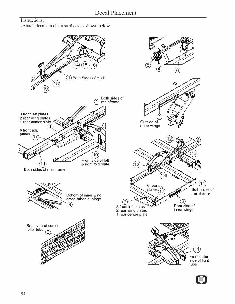
Decal Placement
�
�� �� ��
����
�������������������
��
�
�
�
��
��
��
�����������������������
�������������������
������������������������������������
��������������������������������������������������������
����������������������
�����������������������
��
��
��
��
��
��
�� ����������������������
�����������������������
��������������������������������������������������������
������������������
�������������������������������
�
�����������������������������������������
�������������������������������
Instructions:-Attach decals to clean surfaces as shown below.
55
Parts list / 9200 DF Decal Placement. Date: May 2015 Fig. Part no. Qty Description
1 7600475286 6 Decal, Kongskilde 92002 7600475282 2 Decal, Kongskilde3 7600475265 2 Kongskilde Website Decal4 7600475258 1 Decal, Depth Gauge5 7600475259 1 Decal, Depth Adjust6 7600475287 1 Decal, Depth Indicator7 7600475263 6 Decal, LH Gang Angle8 7600475264 6 Decal, RH Gang Angle9 600475039 4 Decal, Wing Safety10 600475176 2 Decal Wing Fold Lock11 600475180 6 Yellow Reflective Strip12 600475179 4 Red Reflective Strip13 600475178 4 Red-Orange Fluorescent Strip14 600475160 1 Tipping Hazard Decal15 600475169 1 Electrocution Hazard Decal16 600475170 1 Max Speed Decal17 600475253 12 Decal, Sharp Blade18 7600475276 1 Decal, Read Manual19 7600475277 1 Decal, Hose Color Code

56
Assembly CompletionAfter assembly is complete, charge the wheel lift cylinders with a tractor or hydraulic unit, fully extending and retracting the cylinders several times. Hold the hydraulic lever open at the end of the stroke to purge the air from the system. Fully extend the lift cylinders and install the transport safety locks onto the center lift cylinders.
Final InspectionWhen the machine is fully assembled, verify all nuts, bolts and other connections are secure. Be sure to read the Owners Manual before attempting to operate the unit. The Owners Manual provides important instructions and safety precautions that must be followed before attempting to hook up and move the unit after assembly.
The wing fold cylinders must be charged with oil before attempting to fold the cultivator. Disconnect the cylinder rod clevis from the wings and block up the cylinder. Extend and retract the cylinders several times with a tractor or hydraulic unit, holding the lever at the end of the stroke to purge the air from the system. After fold cylinders are charged, re-connect them to the wings.
Slowly fold the wings to the transport position. Insert the wing lock safety pins.
CAUTION: ALWAYS INSTALL THE TRANSPORT LOCK ONTO THE CENTER LIFT CYLINDERS WHEN THE IMPLEMENT IS PLACED IN THE RAISED POSITION FOR TRANSPORT, MAINTENANCE OR STORAGE. Secure with the pin and lock clip provided.
CAUTION: Never transport the implement on public road ways without installing the transport safety chain and SMV sign.
Refer to the Owners Manual for further safety information before attempting to operate or service the unit.
CAUTION: ALWAYS INSTALL THE WING LOCK SAFETY PINS WHEN THE IMPLEMENT IS FOLDED FOR TRANSPORT, MAINTENANCE OR STORAGE.
�������������
�������������������
57
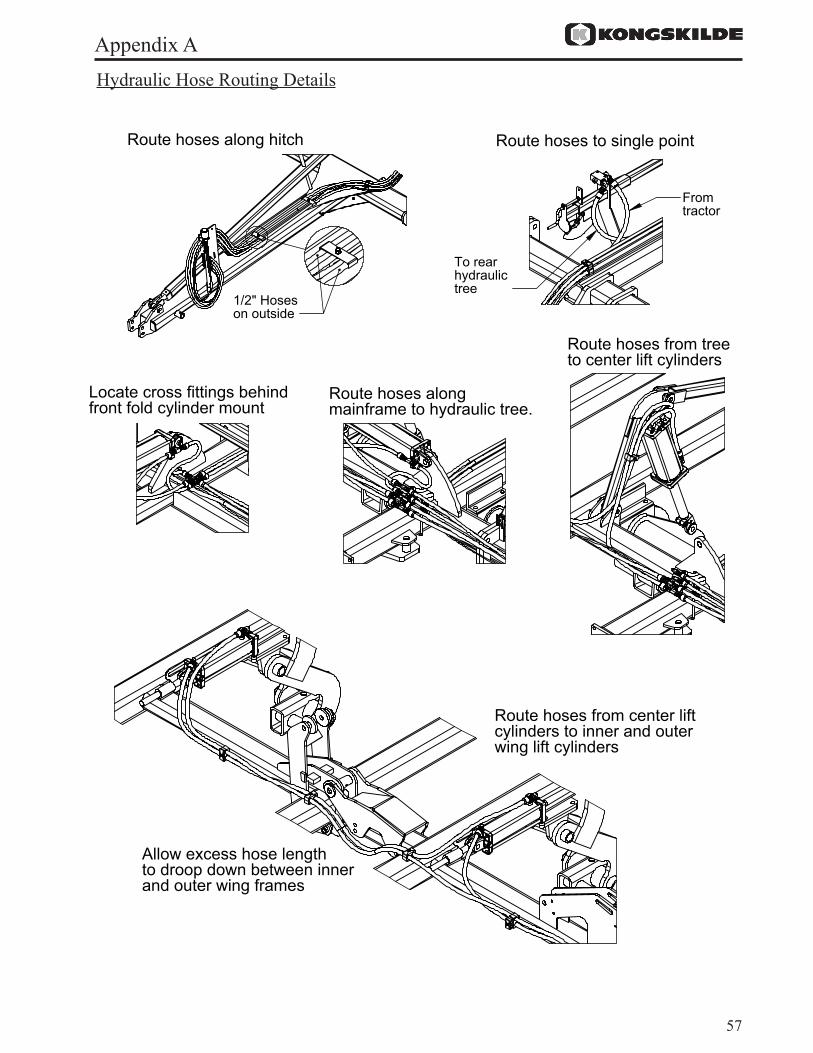
Appendix AHydraulic Hose Routing Details
�����������������������
��������������������
���������������������������
�����������
����������������������
�����������������������������������������������������
���������������������������������������������
���������������������������������������������
���������������������������������������������������������������������������
������������������������������������������������������������������������
58
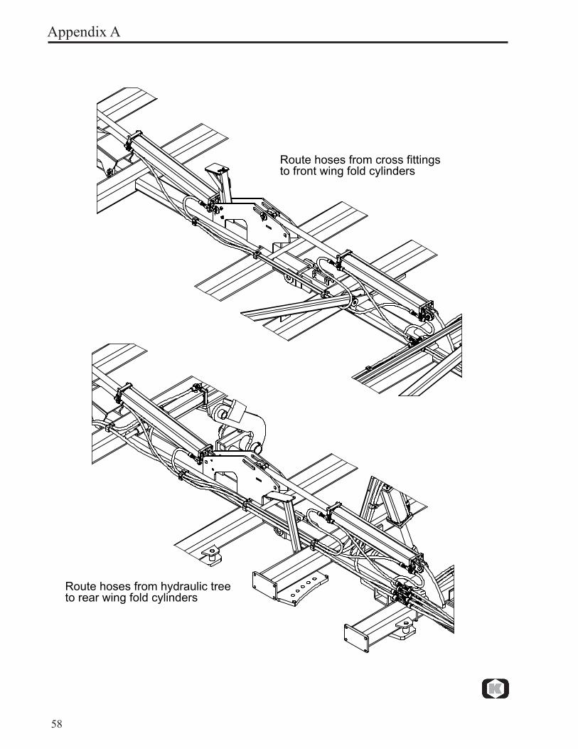
Route hoses from cross fittingsto front wing fold cylinders
Route hoses from hydraulic treeto rear wing fold cylinders
Appendix A
59
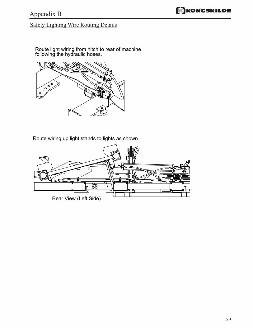
Appendix BSafety Lighting Wire Routing Details
�����������������������������������������������
���������������������
������������������������������������������������������������������������������

60
������
�������
�������
�������
�������
�������
������
�������
�������
�������
�������
�������
������
������
������
�������
�������
�������
������
������
�������
�������
�������
������
����������������
�������������������
����������������������
������������������������
����������������������������
�����������������������
����������
������
�
�
��
��
��
��
��
Appendix CGang & Scraper Tube Layout
61
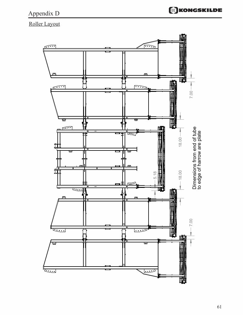
Appendix DRoller Layout
������
�������
������
�������
������
���������������������������
���������������������������
62
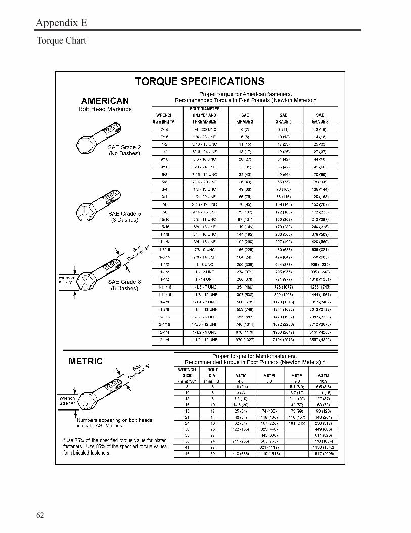
Appendix ETorque Chart

Notes:______________________________________________________________________________________________________________________________________________________________________________________________________________________________________________________________________________________________________________________________________________________________________________________________________________________________________________________________________________________________________________________________________________________________________________________________________________________________________________________________________________________________________________________________________________________________________________________________________________________________________________________________________________________________________________________________________________________________________________________________________________________________________________________________________________________________________________________________________________________________________________________________________________________________________________________________________________________________________________________________________________________________________________________________________________________________________________________________________________________________________________________________________________________________________________________________________________________________________________________________________________________________________________________________________________________________________________________________________________________________________________________________________________________________________________________________________________________________________________________________________________________________________________________________________________________________________________________________________________________________________________________________________________________________________________________________________________________________

760000256 May 2015