9200 power meter - w3.usa.siemens.com · 4 installation considerations installation and maintenance...
TRANSCRIPT
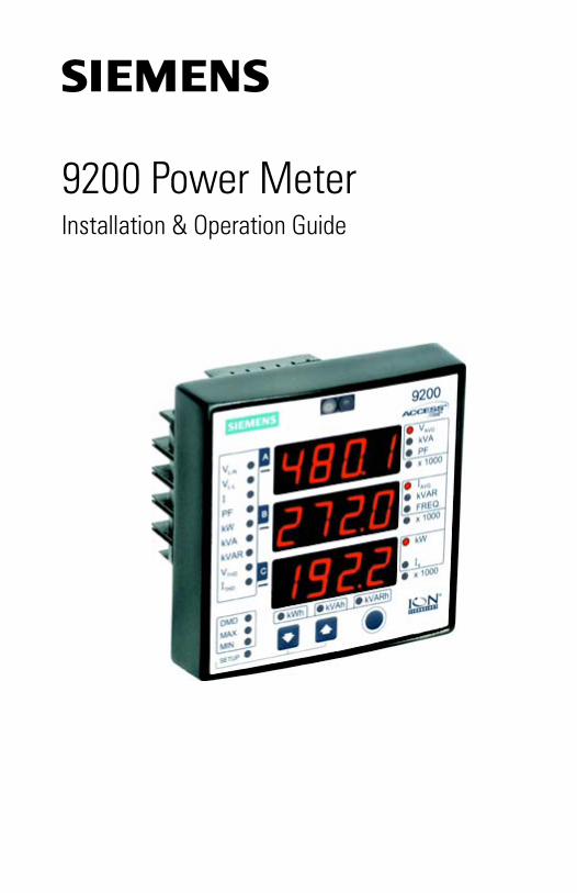
9200 Power MeterInstallation & Operation Guide

Notices
The use of unauthorized parts in the repair of the equipment or tampering by unqualified personnel will result in dangerous conditions that can cause death, serious injury or property damage.
IMPORTANTThe information contained herein is general in nature and not intended for specific application purposes. It does not relieve the user of responsibility to use sound practices in application, installation, operation, and maintenance of the equipment purchased. Siemens reserves the right to make changes at any time without notice or obligations. Should a conflict arise between the general information contained in this publication and the contents of drawings or supplementary material or both, the latter shall take precedence.
QUALIFIED PERSONNELFor the purposes of this manual and product labels, "qualified personnel" is one who is familiar with the installation, construction, or operation of the equipment and the hazards involved. In addition, s/he has the following qualifications:(a) is trained and authorized to energize, de-energize, clear, ground, and tag circuits and
equipment in accordance with established safety practices.(b) is trained in the proper care and use of protective gear equipment such as rubber gloves, hard
hat, safety glasses or face shields, flash clothing, etc., in accordance with established safety procedures.
(c) is trained in rendering first aid.
SUMMARYThese instructions do not purport to cover all details or variations in equipment, nor to provide for every possible contingency to be met in connection with installation, operation, or maintenance. Should further information be desired or should particular problems arise which are not covered sufficiently for the purchaser’s purposes, the matter should be referred to the local the sales office.
THE CONTENTS OF THIS INSTRUCTION MANUAL SHALL NOT BECOME PART OF OR MODIFY ANY PRIOR OR EXISTING AGREEMENT, COMMITMENT OR RELATIONSHIP. THE SALES CONTRACT CONTAINS ALL OBLIGATIONS OF SIEMENS ENERGY & AUTOMATION, INC. THE WARRANTY CONTAINED IN THE CONTRACT BETWEEN THE PARTIES IS THE SOLE WARRANTY OF SIEMENS ENERGY & AUTOMATION, INC.
ACCESS, ISGS, Isolated Multi-Drop, S7-I/O, SBwin, SAMMS-LV, SAMMS-MV,SEAbus,SIEServe, Static Trip III, Wisdom, and WinPM are trademark, Sensitrip and Sentron are registered trade-marks of Siemens Energy & Automation, Inc. SIEMENS is a registered trademark and Windows is a trademark of Microsoft Corporation. ION is a registered trademark of Power Measurement Ltd. All other product names mentioned herein are used for identification purposes only and may be the trademarks or registered trademarks of their respective companies.
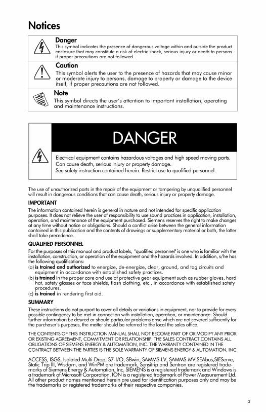
DangerThis symbol indicates the presence of dangerous voltage within and outside the product enclosure that may constitute a risk of electric shock, serious injury or death to persons if proper precautions are not followed.
CautionThis symbol alerts the user to the presence of hazards that may cause minor or moderate injury to persons, damage to property or damage to the device itself, if proper precautions are not followed.
NoteThis symbol directs the user’s attention to important installation, operating and maintenance instructions.
ElectricaI equipment contains hazardous voltages and high speed moving parts.Can cause death, serious injury or property damage.See safety instruction contained herein. Restrict use to qualified personnel.
DANGER
3

4
Installation ConsiderationsInstallation and maintenance of the 9200 meter should only be performed by qualified, competent personnel that have appropriate training and experience with high voltage and current devices. The meter must be installed in accordance with all Local and National Electrical Codes.
DANGER
Failure to observe the following instructions may result in severe injury or death.
During normal operation of the 9200 meter, hazardous voltages are present on its terminal strips, and throughout the connected potential transformer (PT), current transformer (CT), digital (status) input, control power and external I/O circuits. PT and CT secondary circuits are capable of generating lethal voltages and currents with their primary circuit energized. Follow standard safety precautions while performing any installation or service work (i.e. removing PT fuses, shorting CT secondaries, etc).The terminal strips on the meter base should not be user-accessible after installation.Do not use digital output devices for primary protection functions. These include applications where the devices perform energy limiting functions or provide protection of people from injury. Do not use the 9200 in situations where failure of the devices can cause injury or death, or cause sufficient energy to be released that can start a fire. The meter can be used for secondary protection functions.Do not HIPOT/Dielectric test the digital outputs or communications terminals. Refer to the label on the 9200 meter for the maximum voltage level the device can withstand.
CAUTION
Observe the following instructions, or permanent damage to the meter may occur.
The 9200 meter offers a range of hardware options that affect input ratings. The 9200 meter’s serial number label lists all equipped options. Applying current levels incompatible with the current inputs will permanently damage the meter. This document provides installation instructions applicable to each hard-ware option.The 9200 meter’s chassis ground must be properly connected to the switchgear earth ground for the noise and surge protection circuitry to function correctly. Failure to do so will void the warranty.Terminal screw torque: Barrier-type (current, voltage, and relay terminal screws: 1.35 Nm (1.00 ft-lbf) max. Captured-wire type (digital inputs/outputs, communications, power supply: 0.90 Nm (0.66 ft.lbf) max.
FCC NoticeThis equipment has been tested and found to comply with the limits for a Class A digital device, pursuant to Part 15 of the FCC Rules. These limits are designed to provide reasonable protection against harmful interference when the equipment is operated in a commercial environment. This equipment generates, uses, and can radiate radio frequency energy and, if not installed and used in accordance with the instruction manual, may cause harmful interference to radio communications. Operation of this equipment in a residential area is likely to cause harmful interference in which case the user will be required to correct the interference at his own expense.
Standards Compliance
CSA: Certified to CAN/CSA C22.2 No.1010-1
Certified to UL 3111
Mod
el
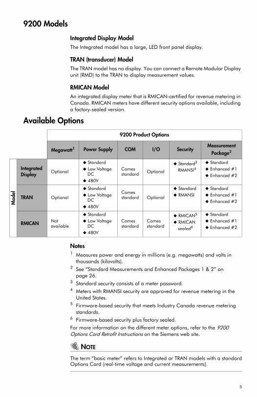
9200 Models
Integrated Display ModelThe Integrated model has a large, LED front panel display.
TRAN (transducer) ModelThe TRAN model has no display. You can connect a Remote Modular Display unit (RMD) to the TRAN to display measurement values.
RMICAN ModelAn integrated display meter that is RMICAN-certified for revenue metering in Canada. RMICAN meters have different security options available, including a factory-sealed version.
Available Options
Notes1 Measures power and energy in millions (e.g. megawatts) and volts in
thousands (kilovolts).2 See “Standard Measurements and Enhanced Packages 1 & 2” on
page 26.3 Standard security consists of a meter password.4 Meters with RMANSI security are approved for revenue metering in the
United States.5 Firmware-based security that meets Industry Canada revenue metering
standards.6 Firmware-based security plus factory sealed.
For more information on the different meter options, refer to the 9200 Options Card Retrofit Instructions on the Siemens web site.
NOTE
The term “basic meter” refers to Integrated or TRAN models with a standardOptions Card (real-time voltage and current measurements).
9200 Product Options
Megawatt1 Power Supply COM I/O SecurityMeasurement
Package2
Integrated Display
Optional
StandardLow Voltage DC480V
Comes standard Optional
Standard3
RMANSI4StandardEnhanced #1Enhanced #2
TRAN Optional
StandardLow Voltage DC480V
Comes standard Optional
StandardRMANSI
StandardEnhanced #1Enhanced #2
RMICAN Not available
StandardLow Voltage DC480V
Comes standard
Comes standard
RMICAN5
RMICAN sealed6
StandardEnhanced #1Enhanced #2
5
Quick InstallThis section can be used by a licensed electrician to install and perform basic meter setup. For more detailed meter setup and use instructions, see the “Using the Meter” section in this guide.
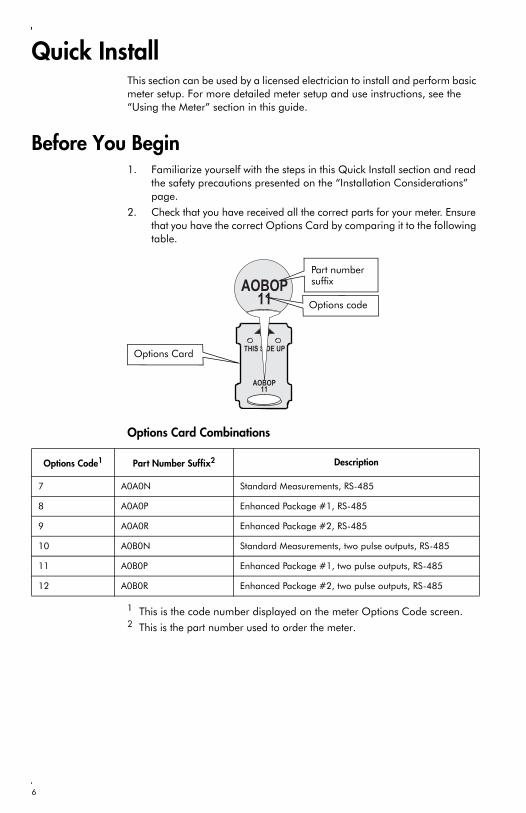
Before You Begin1. Familiarize yourself with the steps in this Quick Install section and read
the safety precautions presented on the “Installation Considerations” page.
2. Check that you have received all the correct parts for your meter. Ensure that you have the correct Options Card by comparing it to the following table.
Options Card Combinations
1 This is the code number displayed on the meter Options Code screen.2 This is the part number used to order the meter.
AOBOP11
THIS SIDE UP
AOBOP11
Part number suffix
Options code
Options Card
Options Code1 Part Number Suffix2 Description
7 A0A0N Standard Measurements, RS-485
8 A0A0P Enhanced Package #1, RS-485
9 A0A0R Enhanced Package #2, RS-485
10 A0B0N Standard Measurements, two pulse outputs, RS-485
11 A0B0P Enhanced Package #1, two pulse outputs, RS-485
12 A0B0R Enhanced Package #2, two pulse outputs, RS-485
6
DANGER
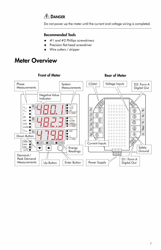
Do not power up the meter until the current and voltage wiring is completed.
Recommended Tools#1 and #2 Phillips screwdriversPrecision flat-head screwdriverWire cutters / stripper
Meter Overview
C
B
A
Phase Measurements
Negative Value Indicator
Demand / Peak Demand Measurements
Down Button
Up Button Enter Button
System Measurements
EnergyReadings
Power SupplyD1: Form ADigital Out
D2: Form A Digital Out
COM1
Front of Meter Rear of Meter
Voltage Inputs
Current InputsSafetyGround
7
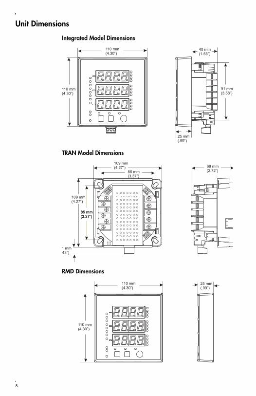
Unit Dimensions
Integrated Model Dimensions
TRAN Model Dimensions
RMD Dimensions
110 mm(4.30”)
110 mm(4.30”)
40 mm(1.58”)
91 mm(3.58”)
25 mm(.99”)
109 mm(4.27”)
86 mm(3.37”)
85 mm(3.37”)86 mm(3.37”)
1 mm43”)
69 mm(2.72”)
109 mm(4.27”)
8
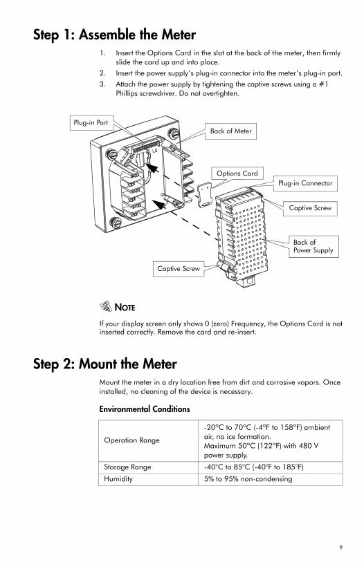
Step 1: Assemble the Meter1. Insert the Options Card in the slot at the back of the meter, then firmly
slide the card up and into place.
2. Insert the power supply’s plug-in connector into the meter’s plug-in port.
3. Attach the power supply by tightening the captive screws using a #1 Phillips screwdriver. Do not overtighten.
NOTE
If your display screen only shows 0 (zero) Frequency, the Options Card is notinserted correctly. Remove the card and re-insert.
Step 2: Mount the MeterMount the meter in a dry location free from dirt and corrosive vapors. Once installed, no cleaning of the device is necessary.
Environmental Conditions
Back of Meter
Back of Power Supply
Options Card
Plug-in Port
Plug-in Connector
Captive Screw
Captive Screw
Operation Range
-20ºC to 70ºC (-4ºF to 158ºF) ambient air, no ice formation.Maximum 50ºC (122ºF) with 480 V power supply.
Storage Range -40°C to 85°C (-40°F to 185°F)
Humidity 5% to 95% non-condensing
9
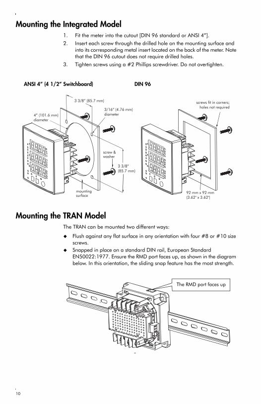
Mounting the Integrated Model1. Fit the meter into the cutout [DIN 96 standard or ANSI 4”].
2. Insert each screw through the drilled hole on the mounting surface and into its corresponding metal insert located on the back of the meter. Note that the DIN 96 cutout does not require drilled holes.
3. Tighten screws using a #2 Phillips screwdriver. Do not overtighten.
Mounting the TRAN ModelThe TRAN can be mounted two different ways:
Flush against any flat surface in any orientation with four #8 or #10 size screws. Snapped in place on a standard DIN rail, European Standard EN50022:1977. Ensure the RMD port faces up, as shown in the diagram below. In this orientation, the sliding snap feature has the most strength.
DIN 96ANSI 4” (4 1/2” Switchboard)
The RMD port faces up
10
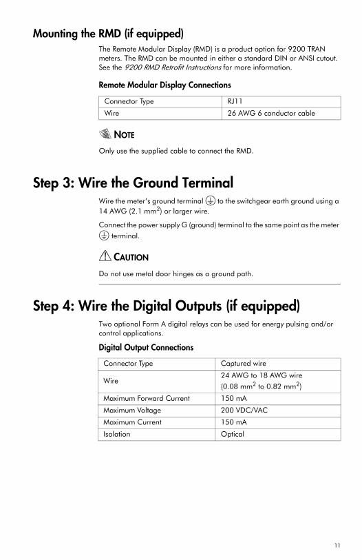
Mounting the RMD (if equipped)The Remote Modular Display (RMD) is a product option for 9200 TRAN meters. The RMD can be mounted in either a standard DIN or ANSI cutout. See the 9200 RMD Retrofit Instructions for more information.
Remote Modular Display Connections
NOTE
Only use the supplied cable to connect the RMD.
Step 3: Wire the Ground TerminalWire the meter’s ground terminal to the switchgear earth ground using a 14 AWG (2.1 mm2) or larger wire.
Connect the power supply G (ground) terminal to the same point as the meter
terminal.
CAUTION
Do not use metal door hinges as a ground path.
Step 4: Wire the Digital Outputs (if equipped)Two optional Form A digital relays can be used for energy pulsing and/or control applications.
Digital Output Connections
Connector Type RJ11
Wire 26 AWG 6 conductor cable
Connector Type Captured wire
Wire24 AWG to 18 AWG wire
(0.08 mm2 to 0.82 mm2)
Maximum Forward Current 150 mA
Maximum Voltage 200 VDC/VAC
Maximum Current 150 mA
Isolation Optical
11
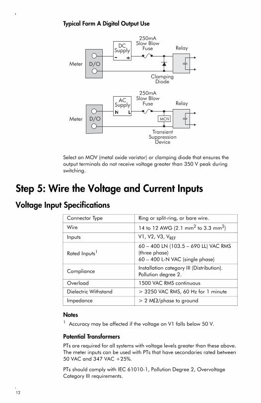
Typical Form A Digital Output Use
Select an MOV (metal oxide varistor) or clamping diode that ensures the output terminals do not receive voltage greater than 350 V peak during switching.
Step 5: Wire the Voltage and Current Inputs
Voltage Input Specifications
Notes1 Accuracy may be affected if the voltage on V1 falls below 50 V.
Potential TransformersPTs are required for all systems with voltage levels greater than these above. The meter inputs can be used with PTs that have secondaries rated between 50 VAC and 347 VAC +25%.
PTs should comply with IEC 61010-1, Pollution Degree 2, Overvoltage Category III requirements.
Connector Type Ring or split-ring, or bare wire.
Wire 14 to 12 AWG (2.1 mm2 to 3.3 mm2)
Inputs V1, V2, V3, VREF
Rated Inputs160 – 400 LN (103.5 – 690 LL) VAC RMS (three phase)60 – 400 L-N VAC (single phase)
ComplianceInstallation category III (Distribution). Pollution degree 2.
Overload 1500 VAC RMS continuous
Dielectric Withstand > 3250 VAC RMS, 60 Hz for 1 minute
Impedance > 2 MΩ/phase to ground
12
CAUTION
In cases where PTs are required, the secondaries should be fused.
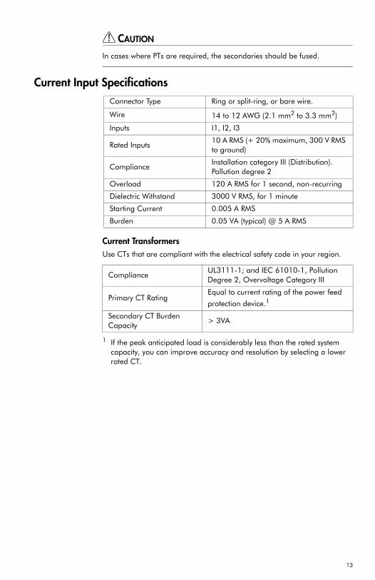
Current Input Specifications
Current TransformersUse CTs that are compliant with the electrical safety code in your region.
1 If the peak anticipated load is considerably less than the rated system capacity, you can improve accuracy and resolution by selecting a lower rated CT.
Connector Type Ring or split-ring, or bare wire.
Wire 14 to 12 AWG (2.1 mm2 to 3.3 mm2)
Inputs I1, I2, I3
Rated Inputs10 A RMS (+ 20% maximum, 300 V RMS to ground)
ComplianceInstallation category III (Distribution). Pollution degree 2
Overload 120 A RMS for 1 second, non-recurring
Dielectric Withstand 3000 V RMS, for 1 minute
Starting Current 0.005 A RMS
Burden 0.05 VA (typical) @ 5 A RMS
ComplianceUL3111-1; and IEC 61010-1, Pollution Degree 2, Overvoltage Category III
Primary CT RatingEqual to current rating of the power feed
protection device.1
Secondary CT Burden Capacity
> 3VA
13
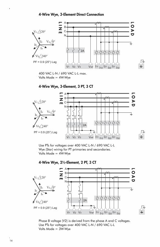
4-Wire Wye, 3-Element Direct Connection
400 VAC L-N / 690 VAC L-L max.Volts Mode = 4W-Wye
4-Wire Wye, 3-Element, 3 PT, 3 CT
Use PTs for voltages over 400 VAC L-N / 690 VAC L-LWye (Star) wiring for PT primaries and secondaries.Volts Mode = 4W-Wye
4-Wire Wye, 2½-Element, 2 PT, 3 CT
Phase B voltage (V2) is derived from the phase A and C voltages.Use PTs for voltages over 400 VAC L-N / 690 VAC L-LVolts Mode = 3W-Wye
LIN
E
LO
AD
LIN
E
LO
AD
LIN
E
LO
AD
14
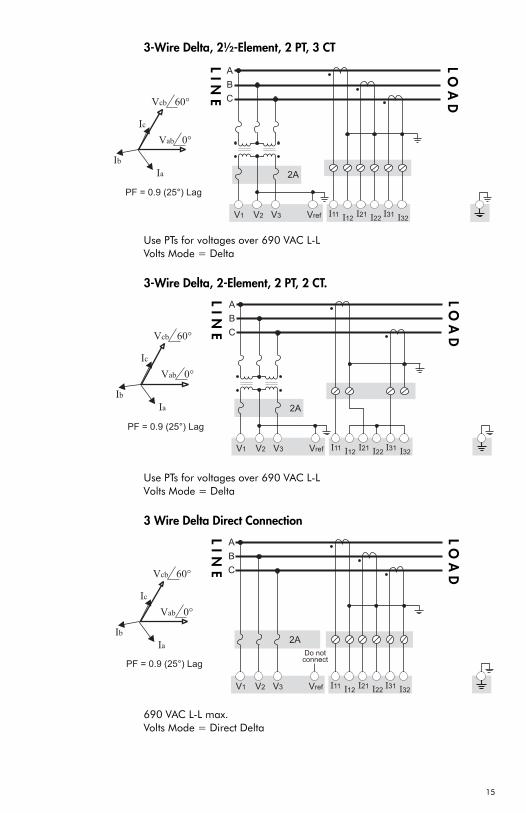
3-Wire Delta, 2½-Element, 2 PT, 3 CT
Use PTs for voltages over 690 VAC L-LVolts Mode = Delta
3-Wire Delta, 2-Element, 2 PT, 2 CT.
Use PTs for voltages over 690 VAC L-LVolts Mode = Delta
3 Wire Delta Direct Connection
690 VAC L-L max.Volts Mode = Direct Delta
LIN
E
LO
AD
LIN
E
LO
AD
LIN
E
LO
AD
15
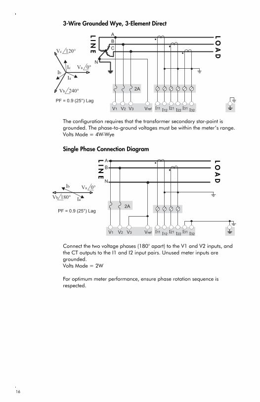
3-Wire Grounded Wye, 3-Element Direct
The configuration requires that the transformer secondary star-point is grounded. The phase-to-ground voltages must be within the meter’s range. Volts Mode = 4W-Wye
Single Phase Connection Diagram
Connect the two voltage phases (180° apart) to the V1 and V2 inputs, and the CT outputs to the I1 and I2 input pairs. Unused meter inputs are grounded.Volts Mode = 2W
For optimum meter performance, ensure phase rotation sequence is respected.
LIN
E
LO
AD
LIN
E
LO
AD
16
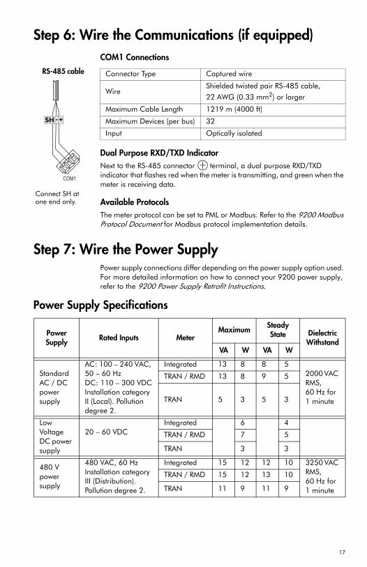
Step 6: Wire the Communications (if equipped)COM1 Connections
Dual Purpose RXD/TXD IndicatorNext to the RS-485 connector terminal, a dual purpose RXD/TXD indicator that flashes red when the meter is transmitting, and green when the meter is receiving data.
Available Protocols The meter protocol can be set to PML or Modbus. Refer to the 9200 Modbus Protocol Document for Modbus protocol implementation details.
Step 7: Wire the Power SupplyPower supply connections differ depending on the power supply option used. For more detailed information on how to connect your 9200 power supply, refer to the 9200 Power Supply Retrofit Instructions.
Power Supply Specifications
Connector Type Captured wire
WireShielded twisted pair RS-485 cable,
22 AWG (0.33 mm2) or larger
Maximum Cable Length 1219 m (4000 ft)
Maximum Devices (per bus) 32
Input Optically isolated
RS-485 cable
Connect SH at one end only.
Power Supply Rated Inputs Meter
Maximum Steady State Dielectric
WithstandVA W VA W
Standard AC / DC power supply
AC: 100 – 240 VAC, 50 – 60 Hz DC: 110 – 300 VDCInstallation category II (Local). Pollution degree 2.
Integrated 13 8 8 52000 VAC RMS, 60 Hz for 1 minute
TRAN / RMD 13 8 9 5
TRAN 5 3 5 3
Low Voltage DC power supply
20 – 60 VDCIntegrated 6 4
TRAN / RMD 7 5
TRAN 3 3
480 V power supply
480 VAC, 60 HzInstallation category III (Distribution). Pollution degree 2.
Integrated 15 12 12 10 3250 VAC RMS, 60 Hz for 1 minute
TRAN / RMD 15 12 13 10
TRAN 11 9 11 9
17

Power Supply Connections
Step 8: Power Up the Meter1. Close the PT fuses (or direct voltage input fuses).
2. Open the CT shorting blocks.
3. Apply power to the meter.
Step 9: Set Up the Meter Using the Front PanelSee “Configuration Mode” on page 23, in the “Using the Meter” section, for detailed instructions on setting up the meter.
The following settings can be configured on your meter using the front panel.
Power Supply Connector Type Wire
Standard AC / DC power supply Captured wire18 to 14 AWG
(0.8 mm2 to 2.1 mm2)
Low Voltage DC power supply Captured wire18 to 14 AWG
(0.8 mm2 to 2.1 mm2)
480 V power supplyRingSplit-ringBare wire
18 to 14 AWG
(0.8 mm2 to 2.1 mm2)
G L+ N-
2 A fuse on L+ and N-DO NOT install the N- fuse in a grounded neutral power system
480 V Power SupplyStandard AC/DC and Low Voltage DC Power Supply
100 mA fuses on L1 and L2
Connections to the L1 and L2 terminals can come from V1 and V2
18
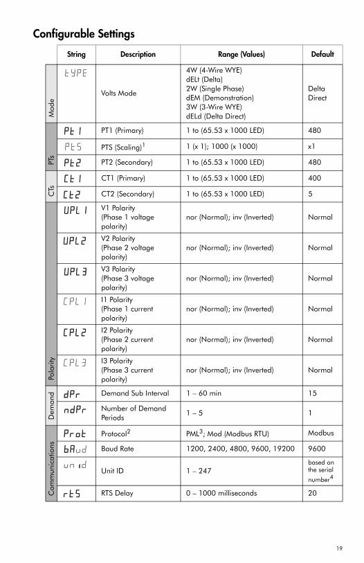
Configurable Settings
String Description Range (Values) Default M
ode
Volts Mode
4W (4-Wire WYE)dELt (Delta)2W (Single Phase)dEM (Demonstration)3W (3-Wire WYE)dELd (Delta Direct)
Delta Direct
PTs
PT1 (Primary) 1 to (65.53 x 1000 LED) 480
PTS (Scaling)1 1 (x 1); 1000 (x 1000) x1
PT2 (Secondary) 1 to (65.53 x 1000 LED) 480
CTs
CT1 (Primary) 1 to (65.53 x 1000 LED) 400
CT2 (Secondary) 1 to (65.53 x 1000 LED) 5
Pola
rity
V1 Polarity(Phase 1 voltage polarity)
nor (Normal); inv (Inverted) Normal
V2 Polarity (Phase 2 voltage polarity)
nor (Normal); inv (Inverted) Normal
V3 Polarity(Phase 3 voltage polarity)
nor (Normal); inv (Inverted) Normal
I1 Polarity(Phase 1 current polarity)
nor (Normal); inv (Inverted) Normal
I2 Polarity(Phase 2 current polarity)
nor (Normal); inv (Inverted) Normal
I3 Polarity(Phase 3 current polarity)
nor (Normal); inv (Inverted) Normal
Dem
and Demand Sub Interval 1 – 60 min 15
Number of Demand Periods
1 – 5 1
Com
mun
icat
ions
Protocol2 PML3; Mod (Modbus RTU) Modbus
Baud Rate 1200, 2400, 4800, 9600, 19200 9600
Unit ID 1 – 247based on the serial
number4
RTS Delay 0 – 1000 milliseconds 20
����
������
�� �
������
����
����
������
������
������
���
������
���
�� ��
� ��� ��
��������
���� ��
� ��
������
19
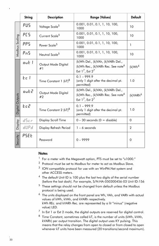
Notes1 For a meter with the Megawatt option, PTS must be set to “x1000.”2 Protocol must be set to Modbus for meter to act as Modbus Slave.3 ION compatible protocol for use with an WinPM.Net system and
other ACCESS meters.4 The default Unit ID is 100 plus the last two digits of the serial number
(before the last dash). For example, S/N:HA-050300456-03 Unit ID:1565 These settings should not be changed from default unless the Modbus
protocol is being used.6 The units displayed on the front panel are Wh, VAh, and VARh with actual
values of kWh, kVAh, and kVARh respectively. kWh REc. and kVARh Rec. are represented by a lit “minus” (negativevalue) LED.
7 In Ext 1 or Ext 2 mode, the digital outputs are reserved for digital control.8 Time Constant, sometimes called kT, is the number of units (kWh, kVAh,
kVARh) per output transition. The digital output uses KY pulsing. This means that the relay changes from open to closed or from closed to open whenever kT units have been measured (20 transitions/second maximum).
Mod
bus
Scal
ing
Voltage Scale5 0.001, 0.01, 0.1, 1, 10, 100, 1000 10
Current Scale5 0.001, 0.01, 0.1, 1, 10, 100, 1000
10
Power Scale5 0.001, 0.01, 0.1, 1, 10, 100, 1000
1
Neutral Scale5 0.001, 0.01, 0.1, 1, 10, 100, 1000
10
Dig
ital O
utpu
ts
Output Mode Digital #1
(k)Wh Del., (k)VAh, (k)VARh Del.,
(k)Wh Rec., (k)VARh Rec. See note6
Ext 17, Ext 27(k)Wh6
Time Constant 1 (kT)80.1 – 999.9(only 1 digit after the decimal pt. permitted)
1.0
Output Mode Digital #2
(k)Wh Del., (k)VAh, (k)VARh Del.,
(k)Wh Rec., (k)VARh Rec. See note6
Ext 17, Ext 27(k)VARh6
Time Constant 2 (kT)80.1 – 999.9
(only 1 digit after the decimal pt. permitted)
1.0
Dis
play Display Scroll Time 0 – 30 seconds (0 = disable) 0
Display Refresh Period 1 – 6 seconds 2
Secu
rity
Password 0 – 9999 0
String Description Range (Values) Default
����
����
������
������
��������
������
��������
������
�� �
�
��������
20
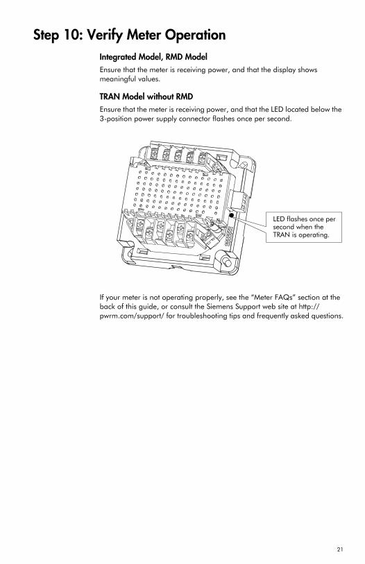
Step 10: Verify Meter OperationIntegrated Model, RMD ModelEnsure that the meter is receiving power, and that the display shows meaningful values.
TRAN Model without RMDEnsure that the meter is receiving power, and that the LED located below the 3-position power supply connector flashes once per second.
If your meter is not operating properly, see the “Meter FAQs” section at the back of this guide, or consult the Siemens Support web site at http://pwrm.com/support/ for troubleshooting tips and frequently asked questions.
LED flashes once per second when the TRAN is operating.
21

Using the MeterWith the meter front panel, you can view parameter values; configure parameters; perform demand resets; perform LED checks; and view meter information. Each of these functions can be accomplished by pressing the Up, Down, and Enter buttons on the front panel. These button actions achieve different results according to the mode that the meter is in:
Display mode (default): view parameter measurementsReset mode: reset demand measurementsConfiguration Select/Edit modes: configure a parameterInformation mode: verify that the front panel display LEDs operate, and view meter information (e.g. meter options, firmware version, etc.)
This section describes front panel navigation within each mode.
NOTE
You have 60 seconds to move from one screen to another. After 60 seconds,the front panel switches back to the default Display mode.
Display Mode In Display mode, you can view values from these measurement groups:
System (total) Per Phase, Energy, DemandPeak Demand
The values you can view depend on which Options package you ordered.
Display Mode Parameter Measurements
1 In Power Factor displays, a negative sign (-) indicates lagging.2 These values not available when Volts Mode is set to Delta or Delta Direct.3 Displays system (total) values.
x 1000 IndicatorWhen the “x 1000” LED is lit, multiply the displayed value by 1000 for the actual value.
Measurement Group Parameters Measured (Megawatt meters)
Parameters Measured(all other models)
System (Total)kVAVG, IAVG, MW, MVA, MVAR,
PF1, Frequency, I4VAVG, IAVG, kW, kVA, kVAR, PF1, Frequency, I4
Phase A, B, and CkVLN
2, kVLL, I, PF1,2, MW2,
MVA2, MVAR2, kVTHD, ITHD
VLN2, VLL, I, PF1,2, kW2, kVA2,
kVAR2, VTHD, ITHD
Energy MWh, MVAh, MVARh kWh, kVAh, kVARh
Demand3 MVA, MVAR, MW, IAVG kVA, kVAR, kW, IAVG
Peak Demand (Max)3 MVA, MVAR, MW, IAVG kVA, kVAR, kW, IAVG
22

Button Functions in Display Mode
Reset ModeIn Reset mode, you can perform a Current (Maximum) Demand reset, a Power (Maximum) Demand reset, or an Energy reset.
Perform a Power (Maximum) Demand Reset to reset these registers: Real Power Demand Maximum; Reactive Power Demand Maximum; or Apparent Power Demand Maximum.
For revenue sealed meters, Energy resets are not permitted.
Button Functions in Reset Mode
Configuration ModeIn Configuration mode, first use the buttons to locate the parameter to be edited (Configuration Select mode), then use the buttons to edit the displayed parameter (Configuration Edit mode).
Configuration Select mode: locate a displayed parameter that requires editing by pressing the Up or Down button.
Mode Button Function
Display Mode
Display mode is
the meter default.
View the previous parameter value.
View the next parameter value.
Move from one measurement group to the next measurement group.
Screen String
Current Maximum Demand Reset
Power Maximum Demand Reset
Energy Reset
��
�
��
Mode Button Function
Reset Mode
ENTER Reset mode by pressing the Enter button and holding for 2 seconds. EXIT Reset mode with the same button sequence.
View the previous reset parameter.
View the next reset parameter.
Program the selected (flashing) parameter reset to the meter.
23
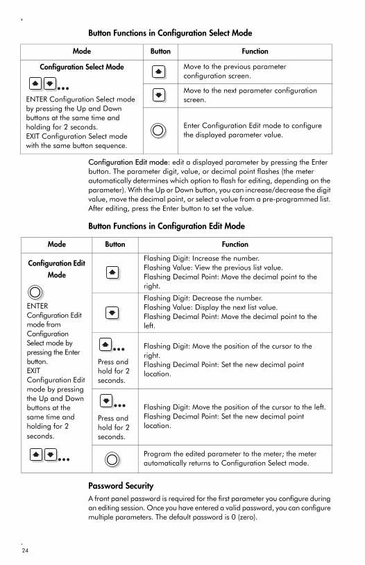
Button Functions in Configuration Select Mode
Configuration Edit mode: edit a displayed parameter by pressing the Enter button. The parameter digit, value, or decimal point flashes (the meter automatically determines which option to flash for editing, depending on the parameter). With the Up or Down button, you can increase/decrease the digit value, move the decimal point, or select a value from a pre-programmed list. After editing, press the Enter button to set the value.
Button Functions in Configuration Edit Mode
Password SecurityA front panel password is required for the first parameter you configure during an editing session. Once you have entered a valid password, you can configure multiple parameters. The default password is 0 (zero).
Mode Button Function
Configuration Select Mode
ENTER Configuration Select mode by pressing the Up and Down buttons at the same time and holding for 2 seconds.EXIT Configuration Select mode with the same button sequence.
Move to the previous parameter configuration screen.
Move to the next parameter configuration screen.
Enter Configuration Edit mode to configure the displayed parameter value.
Mode Button Function
Configuration Edit
Mode
ENTER Configuration Edit mode from Configuration Select mode by pressing the Enter button. EXIT Configuration Edit mode by pressing the Up and Down buttons at the same time and holding for 2 seconds.
Flashing Digit: Increase the number.Flashing Value: View the previous list value.Flashing Decimal Point: Move the decimal point to the right.
Flashing Digit: Decrease the number. Flashing Value: Display the next list value.Flashing Decimal Point: Move the decimal point to the left.
Press and hold for 2 seconds.
Flashing Digit: Move the position of the cursor to the right.Flashing Decimal Point: Set the new decimal point location.
Press and hold for 2 seconds.
Flashing Digit: Move the position of the cursor to the left.Flashing Decimal Point: Set the new decimal point location.
Program the edited parameter to the meter; the meter automatically returns to Configuration Select mode.
24

Meter SettingsConfigurable meter settings are listed in “Configurable Settings” on page 19.
Configuration SoftwareTo monitor, configure, or perform energy resets on your meter, Siemens offers a number of software alternatives. For information on the availability of configuration and system software, refer to our web site at www.sea.siemens.com/access, or contact Customer Service.
Information ModeIn Information mode, you can verify that the front panel LEDs operate, and view meter information (e.g. firmware version).
Verifying that the LEDs and Display FunctionWhen you enter Information mode, every LED on the front panel lights, and each line of the display flashes with four number eights (“8888”) and four decimal points (“....”) per line. This continues for 3 seconds, and indicates that the front panel LEDs and display are operating.
Information Mode Screens
1 The options code specifies the type of Options Card that is in your meter. To view a list of Options Cards with corresponding options codes, refer to the table “Options Card Combinations” on page 6.
Button Functions in Information Mode
Viewing Meter InformationAfter the LED and display operation verification is completed, the meter automatically displays the first of four screens that provide meter information. Press the Up or Down buttons to scroll through these screens.
Screen String
Manufacturer ID NumberNo string; area is used for the meter manufacturer/serial number.
Firmware Version
Original Equipment Manufacturer (OEM)
Meter Options (e.g. enhanced measurements,
digital outputs, communications)1
�
Mode Button Function
Information Mode
ENTER Information mode by pressing the Enter, Up and Down buttons together and holding for 2 seconds. EXIT Information mode with the same button sequence.
Move to the previous Information mode screen.
Move to the next Information mode screen.
25

Standard Measurements and Enhanced Packages 1 & 2
1 These values not available when Volts Mode is set to Delta or Delta Direct.
Standard Enhanced Pkg. 1 Enhanced Pkg. 2
Parameter Display COM Pulse Display COM Pulse Display COM Pulse
Volts L-N Avg
Volts L-N Per Phase1
Volts L-L AvgVolts L-L Per PhaseCurrent AvgCurrent Per PhaseCurrent NeutralPower Total
Power Per Phase1
Reactive Power Total
Reactive Power Per Phase1
Apparent Power Total
Apparent Power Per Phase1
Energy Del. (Imp.)Energy Del. Per Phase (Imp.)Energy Rec. (Exp.)Energy Rec. Per Phase (Exp.)Reactive Energy Del. (Imp.)Reactive Energy Del. (Imp.)Per PhaseReactive Energy Rec. (Exp.)Reactive Energy Rec. (Exp.)Per PhaseApparent EnergyApparent Energy Per PhaseFrequencyPower Factor Total
Power Factor Per Phase1
Current Avg. DemandCurrent Demand Per PhaseCurrent Avg. Peak DemandCurrent Peak Demand Per PhasePower DemandPower Peak DemandReactive Power DemandReactive Power Peak DemandApparent Power DemandApparent Power Peak DemandTHD Voltage Per PhaseTHD Current Per Phase
26

Meter FAQsQ: Why is my meter’s display screen only showing 0 (zero) or 60 Frequency?
A: The Options Card is not inserted correctly. Remove the card and re-insert.
Q: How do I interpret the front panel displays?
A: Look in Step 9 under Configurable Settings
Q: Can the digital outputs be reprogrammed? What are the ET 1 and ET 2 settings?
A: The digital outputs can each be configured to pulse for one of the following: (k)Wh Del., (k)VAh, (k)VARh Del., (k)Wh Rec., (k)VARh Rec. Ext 1, Ext 2. In Ext 1 and Ext 2 mode, the digital output state is determined by a Modbus register value (1 for ON and 0 for OFF).
Q: How do I view firmware and options card number?
A: Hold down all three buttons at the same time for approximately 5 seconds. Scroll to the desired screen. Hold down all three buttons again to return to normal operation.
Q: The meter is not communicating with the network. What should I check?
A: Check Protocol, Unit ID number, and Baud rate. Ensure only one end of shield is connected to avoid ground loop connections.
27

Siemens Energy & Automation, Inc.Power Management Technologies3333 Old Milton ParkwayAlpharetta, GA 30005
© 2005 Siemens Energy & Automation, Inc.Siemens is a registered trademark of Siemens AG. Specifications are subject to change without notice.
For Nearest Sales Office1.800.964.4114www.sea.siemens.comsales/salesoffices.html
Windows is a trademark and Microsoft is a registered trademark of Microsoft Corporation.All others are of Siemens AG.
Revision Date: Jan. 3, 2006Order No. 70005-0196-05PDF 0800 Printed in the U.S.A.
For More Information Visitwww.sea.siemens.com/access