9/2013 technical manual mdt rf line coupler knx rf+ · pdf file9/2013 technical manual mdt rf...
TRANSCRIPT

MDT technologies GmbH � 51766 Engelskirchen � Papiermühle 1
Tel.: +49-2263-880 � Fax: +49-2263-4588 � [email protected] � www.mdt.de
1
9/2013
Technical Manual
MDT RF Line Coupler KNX RF+
RF-LK001.01

Technical Manual RF Line Coupler RF‐LK
MDT technologies GmbH � 51766 Engelskirchen � Papiermühle 1
Tel.: +49-2263-880 � Fax: +49-2263-4588 � [email protected] � www.mdt.de 2
1 Content 1 Content ................................................................................................................................................. 2
2 Overview ............................................................................................................................................... 3
2.1 Usage ............................................................................................................................................. 3
2.2 Exemplary circuit diagram ............................................................................................................. 3
2.3 Functions ....................................................................................................................................... 4
2.4 Structure & Handling ..................................................................................................................... 4
2.5 Topology & Areas of use ................................................................................................................ 5
3 ETS‐Parameters .................................................................................................................................... 6
3.1 Main Line ....................................................................................................................................... 6
3.2 Sub/RF Line .................................................................................................................................... 8
4 Settings at the ETS .............................................................................................................................. 10
4.1 Topology of the project ............................................................................................................... 10
4.2 Telegram Forwarding .................................................................................................................. 12
4.3 Generating Filter Table ................................................................................................................ 12
4.4 Preview Filter Table ..................................................................................................................... 13
4.5 Approach at startup .................................................................................................................... 14
5 Index ................................................................................................................................................... 15
5.1 Register of illustrations ................................................................................................................ 15
5.2 List of tables................................................................................................................................. 15
6 Attachment ......................................................................................................................................... 16
6.1 Statutory requirements ............................................................................................................... 16
6.2 Routine disposal .......................................................................................................................... 16
6.3 Assemblage .................................................................................................................................. 16
6.4 Datasheet .................................................................................................................................... 17

Technical Manual RF Line Coupler RF‐LK
MDT technologies GmbH � 51766 Engelskirchen � Papiermühle 1
Tel.: +49-2263-880 � Fax: +49-2263-4588 � [email protected] � www.mdt.de 3
2Overview
2.1Usage The RF‐LK connects KNX Twisted Pair lines with KNX RF+ lines. So the Line Coupler works as connector between these both transmission medium. The RF Line Coupler can evaluate adjusted filter settings at the transmission between both medium. These can block certain addressing types or work with automatically or manually generated filter tables. The RF‐LK001.01 supports the new KNX RF+ protocol in system mode and is available in the version for ETS3/4 or ETS5. Detailed information for planning and working with radio lines via the KNX RF+ protocol can be downloaded at http://www.mdt.de/EN_Downloads_Manuals.html.
2.2Exemplarycircuitdiagram
Figure 1: Exemplary circuit diagram

Technical Manual RF Line Coupler RF‐LK
MDT technologies GmbH � 51766 Engelskirchen � Papiermühle 1
Tel.: +49-2263-880 � Fax: +49-2263-4588 � [email protected] � www.mdt.de 4
2.3Functions If the Coupler receives telegrams receives telegrams, which are physical addressed, the RF Line Coupler compares the physical address of the transmitter with its own and decides whether the address should be forwarded or not. Broadcast telegrams, which are used for programming devices, are always forwarded if needed. Telegrams, which are addressed by group addresses, are evaluated by considering the individual settings of the RF Line Coupler. During the normal mode (Default‐Settings), telegrams are forwarded, which are in the filter table. If the Coupler does not receive a confirmation for a forwarded telegram or if a device recognizes a transmission error, the Coupler will repeat the telegram, concerning its settings, up to three times.
2.4Structure&Handling
Figure 2: Overview hardware

Technical Manual RF Line Coupler RF‐LK
MDT technologies GmbH � 51766 Engelskirchen � Papiermühle 1
Tel.: +49-2263-880 � Fax: +49-2263-4588 � [email protected] � www.mdt.de 5
2.5Topology&Areasofuse The MDT RF Line Coupler can be used in every case, when KNX Twisted Pair lines and KNX RF+ lines should be connected. Although the MDT RF Line Coupler transmits only the telegrams from Twisted Pair to KNX RF+ and vice versa, which are set in the parameters. By using the new KNX RF+ standard, old gateways, which were earlier necessary for transmission on RF‐lines, are no longer used. The communication at RF Line is in the same way self‐sufficient as the communication at TP Lines. The following figure shows an exemplary topology of combining TP Lines and RF Lines:
Figure 3: Topology
The topology at using KNX RF+ devices is the same as using normal TP devices. For connecting both lines, the KNX RF+ Line Coupler is necessary. Every TP Line must have an own bus power supply. KNX RF+ Lines does not need any external power supply and there is no limitation to 64 devices per line. At RF+ lines only the bus load is the limitation of each line. All MDT RF+ lines work without any batteries and can be connected directly to 230V AC.

Technical Manual RF Line Coupler RF‐LK
MDT technologies GmbH � 51766 Engelskirchen � Papiermühle 1
Tel.: +49-2263-880 � Fax: +49-2263-4588 � [email protected] � www.mdt.de 6
3ETS‐Parameters
3.1MainLine
Figure 4: Main Line
The following chart shows the available settings for the submenu “Main Line”: ETS‐text Dynamic range
[default value] comment
Configuration
groups: filter, physical: block groups, physical: filter groups: route, physical: filter configure
‐ Block: no telegram is routed. ‐ Filter: Only telegrams are routed which are entered in the filter table. ‐ Route: the telegrams are routed. ‐ Configure: the following parameters can be set individually. This parameter is to be set depending on the planed configuration.
Group telegrams 1. block 2. filter
1. No group telegram is transmitted. 2. Only group telegrams are routed which are entered in the filter table. ETS 3/4 produces the filter table automatically.
Main group telegrams 14/15 1. block 2. transmit all
1. Group telegrams with the main group 14 or 15 (e.g. 14/1) are not routed. 2. Group telegrams with the main group 14 or 15 (e.g. 14/1) are routed.

Technical Manual RF Line Coupler RF‐LK
MDT technologies GmbH � 51766 Engelskirchen � Papiermühle 1
Tel.: +49-2263-880 � Fax: +49-2263-4588 � [email protected] � www.mdt.de 7
Physical telegrams 1. block
2. filter 1. No physical telegram is transmitted. 2. Only physical telegrams are routed based on physical address.
Physical: Repetition if errors on main line
1. no 2. reduced 3. normal
If a transmission error (e.g. due to missing receiver) is found when sending a physical telegram on the main line: 1. The physical telegram is not repeated. 2. The physical telegram will be repeated only one time. 3. The physical telegram is repeated up to 3 times.
Group: Repetition if errors on main line
1. no 2. reduced 3. normal
If a transmission error (e.g. due to missing receiver) is found when sending a group telegram on the main line: 1. The group telegram is not repeated. 2. The group telegram will be repeated only one time. 3. The group telegram is repeated up to 3 times.
Telegram confirmations on line
1. always 2. if routed
1. Each telegram on the main line is confirmed (ACK). 2. Only telegrams which are to be routed are confirmed on the main line (ACK).
Send confirmation on own telegrams
1. yes 2. no
1. Every telegram on the main line is confirmed with its own ACK (from the Line coupler). 2. No confirmation with own ACK
Table 1: Main Line

Technical Manual RF Line Coupler RF‐LK
MDT technologies GmbH � 51766 Engelskirchen � Papiermühle 1
Tel.: +49-2263-880 � Fax: +49-2263-4588 � [email protected] � www.mdt.de 8
3.2Sub/RFLine
Figure 5: Sub/RF Line
The following chart shows the available settings for the submenu “Line”: ETS‐text Dynamic range
[default value] comment
Configuration groups: filter, physical: block groups, physical: filter groups: route, physical:
filterconfigure
‐ Block: no telegram is routed. ‐ Filter: Only telegrams are routed which are entered in the filter table. ‐ Route: the telegrams are routed. ‐ Configure: the following parameters can be set individually. This parameter is to be set depending on the planed configuration.
Group telegrams 1. block 2. filter
1. No group telegram is transmitted. 2. Only group telegrams are routed which are entered in the filter table. The ETS 3/4 produces the filter table automatically.
Sub group telegrams 14/15 1. block 2. transmit all
1. Group telegrams with the sub group14 or 15 (e.g. 14/1) are not routed. 2. Group telegrams with the sub group14 or 15 (e.g. 14/1) are routed.
Physical telegrams 1. block 2. filter
1. No physical telegram is transmitted. 2. Only physical telegrams are routed based on physical address.

Technical Manual RF Line Coupler RF‐LK
MDT technologies GmbH � 51766 Engelskirchen � Papiermühle 1
Tel.: +49-2263-880 � Fax: +49-2263-4588 � [email protected] � www.mdt.de 9
Physical: Repetition if errors on sub line
1. no 2. reduced 3. normal
If a transmission error (e.g. due to missing receiver) is found when sending a physical telegram on the sub line: 1. The physical telegram is not repeated. 2. The physical telegram will be repeated only one time. 3. The physical telegram is repeated up to 3 times.
Group: Repetition if errors on sub line
1. no 2. reduced 3. normal
If a transmission error (e.g. due to missing receiver) is found when sending a group telegram on the sub line: 1. The group telegram is not repeated. 2. The group telegram will be repeated only one time. 3. The group telegram is repeated up to 3 times.
Telegram confirmations on line
1. always 2. if routed
1. Each telegram on the sub line is confirmed (ACK). 2. Only telegrams which are to be routed are confirmed on the sub line (ACK).
Send confirmation on own telegrams
1. yes 2. no
1. Every telegram on the sub line is confirmed with its own ACK (from the Line coupler). 2. No confirmation with own ACK
Table 2: Sub/RF Line

Technical Manual RF Line Coupler RF‐LK
MDT technologies GmbH � 51766 Engelskirchen � Papiermühle 1
Tel.: +49-2263-880 � Fax: +49-2263-4588 � [email protected] � www.mdt.de 10
4SettingsattheETS
4.1Topologyoftheproject The project is identical with projects with Twisted Pair Line Coupler, but every connection from TP to radio can only be realized by using the Line Coupler RF‐LK001.01. An exemplary project could look like this:
Figure 6: Topology Example
At the ETS, the topology looks like this:
Figure 7: Topology ETS

Technical Manual RF Line Coupler RF‐LK
MDT technologies GmbH � 51766 Engelskirchen � Papiermühle 1
Tel.: +49-2263-880 � Fax: +49-2263-4588 � [email protected] � www.mdt.de 11
If the presentation of one radio line is expanded, it looks like this:
Figure 8: Radio Line ETS
As shown in the upper picture, a radio line in ETS has an easy design and looks like a normal TP‐line. The Line Coupler, which must always be member 0, is the “connector” between Twisted Pair and KNX RF+. Every KNX RF+ device is used as a normal TP‐device. An additional power supply is not necessary for radio lines, because every KNX RF+ device has a connector for 230V AC. The main line has the same design like a normal TP‐line:
Figure 9: Main Line ETS

Technical Manual RF Line Coupler RF‐LK
MDT technologies GmbH � 51766 Engelskirchen � Papiermühle 1
Tel.: +49-2263-880 � Fax: +49-2263-4588 � [email protected] � www.mdt.de 12
4.2TelegramForwarding Two ways of telegram forwarding are differentiated:
1. Telegrams with physical addressing 2. Telegrams with group addressing
The addressing with physical addresses is, for example, used at the programming of the devices, whereas the addressing by group addresses is used at the “normal” bus communication. The behavior of the Line Coupler at telegrams with physical addressing is easy. If the physical target address is in the line of the Line Coupler, the telegram is forwarded else not. The behavior of the Line Coupler at group telegrams is defined by filter tables. For that matter, the filter tables indicate the group addresses, which are forwarded from KNX TP to KNX RF+ and vice versa. For doing this, the Line Coupler listens at the TP line and at the RF+ line to all group telegrams and compares the target address with group addresses in the filter table. If the target address is in the filter table, the telegram will be forwarded to the other medium else not.
4.3GeneratingFilterTable The filter table will be generated automatically from the ETS. However there are exceptions in which it can be useful to add group addresses manually to the filter table. Every group address, which connects communication objects of TP lines and RF+ lines, are automatically added to the filter table. So all group address are in the filter table, which are necessary for the communication between the devices. As mentioned at the beginning of this paragraph, in some cases it can be useful to add addresses manually to the filter table, e.g. for displaying the group addresses in Visualizations or for using the group address at diagnostics at the group/bus monitoring. For adding the group addresses manually, the group address must be selected in the ETS and the option “Pass through Line Coupler” must be set from No to Yes:
Figure 10: Set Filter Table manually
It should be considered, that manual added group addresses can pass all Line Couplers. So the bus load is increased on all lines. So only group addresses should be added, which are really needed.

Technical Manual RF Line Coupler RF‐LK
MDT technologies GmbH � 51766 Engelskirchen � Papiermühle 1
Tel.: +49-2263-880 � Fax: +49-2263-4588 � [email protected] � www.mdt.de 13
4.4PreviewFilterTable A preview of the current Filter table can be seen as follows:
Figure 11: Preview Filter table
For that purpose, you click with the right mouse button at the Line Coupler. Now you can choose the entry “Preview Filter table…” in the context menu. The Filter table shows every group address, which will be transmitted from TP to radio and vice versa:
Figure 12: Preview Filter table 2

Technical Manual RF Line Coupler RF‐LK
MDT technologies GmbH � 51766 Engelskirchen � Papiermühle 1
Tel.: +49-2263-880 � Fax: +49-2263-4588 � [email protected] � www.mdt.de 14
4.5Approachatstartup After all devices are integrated in the project, appropriate the right topology like described in4.1 Topology of the project, the devices can be parameterized according to the own wishes. It is recommended to use the RF‐LK001.01 with the default settings. The right course of action at the startup is very important, because otherwise the exchange of data between TP and radio cannot be guaranteed.
1. Programming the Line Coupler By programming the Line Coupler, the current settings are load into the Line Coupler. Furthermore the current Filter table is loaded into the Line Coupler.
2. Programming der MDT RF+ Devices By programming the KNX RF+ Devices the parameter settings are load in the memory of the devices. This procedure is the same at radio devices as at TP‐devices. Furthermore the programming of the KNX RF+ devices writes the domain address into the KNX RF+ devices. This domain address is unique for each line and guarantees that all device of a line can communicate with each other, but devices out of the lines does not disturb this devices.
Important: At every change of the project, the Line Coupler must be load again(Download Application). Afterwards every device, which is changed, must be programmed again. If Changes at the topology of the project are made, at first the Line Coupler must be downloaded and afterwards every device, which is involved of the change of the topology, must be downloaded again.

Technical Manual RF Line Coupler RF‐LK
MDT technologies GmbH � 51766 Engelskirchen � Papiermühle 1
Tel.: +49-2263-880 � Fax: +49-2263-4588 � [email protected] � www.mdt.de 15
5Index
5.1Registerofillustrations Figure 1: Exemplary circuit diagram ........................................................................................................ 3 Figure 2: Overview hardware .................................................................................................................. 4 Figure 3: Topology ................................................................................................................................... 5 Figure 4: Main Line .................................................................................................................................. 6 Figure 5: Sub/RF Line ............................................................................................................................... 8 Figure 6: Topology Example .................................................................................................................. 10 Figure 7: Topology ETS .......................................................................................................................... 10 Figure 8: Radio Line ETS ........................................................................................................................ 11 Figure 9: Main Line ETS ......................................................................................................................... 11 Figure 10: Set Filter Table manually ...................................................................................................... 12 Figure 11: Preview Filter table .............................................................................................................. 13 Figure 12: Preview Filter table 2 ............................................................................................................ 13
5.2Listoftables Table 1: Main Line ................................................................................................................................... 7 Table 2: Sub/RF Line ................................................................................................................................ 9

Technical Manual RF Line Coupler RF‐LK
MDT technologies GmbH � 51766 Engelskirchen � Papiermühle 1
Tel.: +49-2263-880 � Fax: +49-2263-4588 � [email protected] � www.mdt.de 16
6 Attachment
6.1 Statutory requirements The above‐described devices must not be used with devices, which serve directly or indirectly the purpose of human, health‐ or lifesaving. Further the devices must not be used if their usage can occur danger for humans, animals or material assets. Do not let the packaging lying around careless, plastic foil/ ‐bags etc. can be a dangerous toy for kids.
6.2 Routine disposal Do not throw the waste equipment in the household rubbish. The device contains electrical devices, which must be disposed as electronic scrap. The casing contains of recyclable synthetic material.
6.3 Assemblage
Risk for life of electrical power!
All activities on the device should only be done by an electrical specialist. The county specific regulations and the applicable EIB‐directives have to be observed.

RF-LK001.02
MDT KNX RF+ Line Coupler
The MDT KNX RF+ Line Coupler connects MDT KNX RF+ devices to the KNX bus. The Line Coupler offers extensive ilter functions to reduce the KNX RF+ bus load.
The Line Coupler allows bidirectional KNX RF+ communication in the new system mode to the following devices:
- KNX RF+ Glas Push Button Plus with Actuator 4/8-fold
- KNX RF+ Push Button Plus 2/4/6/8-fold
- KNX RF+ Push Button Plus with Actuator 2/4/6/8-fold
- KNX RF+ Switching Actuator 1/2-fold
- KNX RF+ Shutter Actuator 1-fold
- more devices under developement
By connection via the MDT KNX RF+ Line Coupler the attached KNX RF+ devices can be directly paramerized with the
ETS. Special tools or ETS plugins are not required. A speciic parameterization of the Line Coupler is not necessary.
The MDT KNX RF+ Line Coupler is available as lush mounted installation device for ixed installation in dry rooms.
For project design and commissioning of the MDT KNX RF+ Line Coupler it is recommended to use the ETS5.
Please download the application software at www.mdt.de/Downloads.html
• Production in Germany, certiied according to ISO 9001• KNX RF+ line coupler to connect MDT KNX RF+ devices like MDT Push Button RF+ or MDT Glass Push Button RF+
• New KNX RF+ protocal in system mode• Commissioning via ETS5
• Compatible to the new KNX RF+ speciication• Filter functions to reduce bus load• Flush mounted in socket• Dimensions (W x H x D): 41mm x 41mm x 22mm• Integrated bus coupling unit• 3 years warranty
MDT KNX RF+ Line Coupler, Flush mounted
Version
RF-LK001.02 KNX RF+ Line Coupler Flush mounted, commissioning with ETS5
MDT technologies GmbH • 51766 Engelskirchen • Papiermühle 1
Tel.: + 49 - 2263 - 880 • Fax: + 49 - 2263 - 4588 • [email protected] • www.mdt.de
Stand: 0716
DIN EN ISO 9001
TAW Cert
Zert.Nr.1905606
N
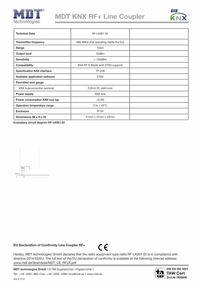
Technical Data RF-LK001.02
Transmitter frequency 868,3MHz (For operating inside the EU)
Range 150m
Output level 10dBm
Sensitivity >-105dBm
Compatibility KNX RF S-Mode (with ETS5 support)
Speciication KNX interface TP-256
Available application software ETS5
Permitted wire gauge
KNX busconnection terminal 0,8mm Ø, solid core
Power supply KNX bus
Power consumption KNX bus typ. <0,3W
Operation temperature range 0 to + 45°C
Enclosure IP 20
Dimensions (W x H x D) 41mm x 41mm x 24mm
Examplary circuit diagram RF-LK001.02
MDT KNX RF+ Line Coupler
EU Declaration of Conirmity Line Coupler RF+
Hereby, MDT technologies GmbH declares that the radio equipment type radio RF-LK001.02 is in compliance with directive 2014/53/EU. The full text of the EU declaration of conirmity is available at the following internet address: www.mdt.de/download/MDT_CE_RFLK.pdf
MDT technologies GmbH • 51766 Engelskirchen • Papiermühle 1
Tel.: + 49 - 2263 - 880 • Fax: + 49 - 2263 - 4588 • [email protected] • www.mdt.de
Stand: 0716
DIN EN ISO 9001
TAW Cert
Zert.Nr.1905606
N