94069 solar garden light post - harbor freight...
TRANSCRIPT

94069ASSEMBLING INSTRUCTIONS
3491 Mission Oaks Blvd., Camarillo, CA 93011
Visit our Web site at http://www.harborfreight.com
Copyright © 2005 by Harbor Freight Tools®. All rights reserved. No portion of thismanual or any artwork contained herein may be reproduced in any shape or formwithout the express written consent of Harbor Freight Tools.
For technical questions and replacement parts, please call 1-800-444-3353
SOLAR GARDENLIGHT POST

SKU 94069 For technical questions, please call 1-800-444-3353. Page 2
DESCRIPTION75” High
9” Overall DiameterWhite Die Cast Aluminum Post12 LED Bulbs with 2.5 Watt Solar Panel; Light Color: WhiteAutomatic ON/OFF1.2V x 2800 mAh NiCd Recharg. Batteries-“C” (Qty. 3, Included)Slider (AUTO/OFF)8 to 10 Hours When Fully Charged11.4 Lbs.
ITEM
SPECIFICATIONS
SAVE THIS MANUAL
You will need the manual for the safety warnings and precautions, assemblyinstructions, operating and maintenance procedures, parts list and diagram. Keepyour invoice with this manual. Write the invoice number on the inside of the frontcover. Keep the manual and invoice in a safe and dry place for future reference.
SAFETY WARNINGS AND PRECAUTIONS
1. KEEP WORK AREA CLEAN. Cluttered areas invite injuries.
2. OBSERVE WORK AREA CONDITIONS. Keep work area well lit.
3. DO NOT OPERATE BATTERY POWERED EQUIPMENT IN EXPLOSIVEATMOSPHERES, SUCH AS IN THE PRESENCE OF FLAMMABLE LIQUIDS,GASES, OR DUST. Battery powered equipment creates sparks which may igniteflammables.
4. CHECK FOR DAMAGED PARTS. Before using any product, any part thatappears damaged should be carefully checked to determine that it will perform itsintended function. Check for any broken or damaged parts and any otherconditions that may affect its operation. Replace or repair damaged or worn partsimmediately.
5. USE SAFETY EQUIPMENT. WEAR ANSI APPROVED SAFETY IMPACT EYEGOGGLES WHEN ASSEMBLING AND INSTALLING THE SOLAR GARDENLIGHT POST.
6. REPLACEMENT PARTS AND ACCESSORIES. When servicing, use onlyidentical replacement parts. Use of any other parts will void the warranty.
7. ALWAYS CHECK HARDWARE AND ASSEMBLED PARTS AFTERASSEMBLING. All connections should be tight and hardware tightened.
8. KEEP CHILDREN AWAY. Children must never be allowed in the work area whenassembling this product. Do not let them to attempt to climb or play on the SolarGarden Light Post.
Overall HeightLightMaterialsLight SourcePhoto CellBattery TypePower SwitchNight Running TimeNet Weight
REV 05/05

SKU 94069 For technical questions, please call 1-800-444-3353. Page 3
9. DRESS SAFELY. Do not wear loose clothing or jewelry as they can become caughtin moving parts. Wear a protective hair covering to prevent long hair from becom-ing caught in the moving parts.
10. DO NOT OVERREACH. Keep proper footing and balance at all times. Properfooting and balance enables better control of the Solar Garden Light Post in unex-pected situations.
11. STAY ALERT. Watch what you are doing at all times. Use common sense. Do notassemble this product when you are tired or distracted from the job at hand.
12. REPLACEMENT PARTS AND ACCESSORIES. When servicing, use only iden-tical replacement parts. Only use accessories intended for use with this product.Approved accessories are available from Harbor Freight Tools.
13. MAINTAIN PRODUCT WITH CARE. Do not use damaged equipment. Tag dam-aged equipment “Do not use” until repaired.
14. DO NOT FORCE THE EQUIPMENT. USE THE CORRECT EQUIPMENT FORYOUR APPLICATION. The correct equipment will do the job better and safer atthe rate for which it is designed. Do not use small equipment, tools, or attach-ments to do the work of larger industrial equipment, tools, or attachments. Do notuse this product for a purpose for which it was not intended.
15. STORE IDLE EQUIPMENT OUT OF REACH OF CHILDREN AND OTHER UN-TRAINED PERSONS. Battery powered equipment can be dangerous in the handsof children and untrained users.
16. CHECK FOR MISALIGNMENT OR BINDING OF PARTS, BREAKAGE OFPARTS, AND ANY OTHER CONDITION THAT MAY AFFECT THE SOLAR GAR-DEN LIGHT POST’S OPERATION. If damaged, have the Solar Garden LightPost serviced before using. Many accidents are caused by poorly maintainedequipment.
17. EQUIPMENT SERVICE MUST BE PERFORMED ONLY BY QUALIFIED RE-PAIR PERSONNEL. Service or maintenance performed by unqualified personnelcould result in a risk of injury.
18. WHEN SERVICING EQUIPMENT, USE ONLY IDENTICAL REPLACEMENTPARTS. FOLLOW INSTRUCTIONS IN THE ”INSPECTION, MAINTENANCE,AND CLEANING” SECTION OF THIS MANUAL. Use of unauthorized parts orfailure to follow maintenance instructions may create a risk of electric shock orinjury.
SKU 94069 For technical questions, please call 1-800-444-3353. Page 4
19. PROPER BATTERY CARE: Battery leakage may occur under extreme usageor temperature conditions. If battery fluid comes in contact with skin, wash withsoap and water and rinse with lemon juice and vinegar. If the fluid comes intocontact with the eyes, flush with water for several minutes and contact a doctorimmediately. Never burn the Battery, as it can explode in the fire. Do not use theSolar Garden Light Post with a leaking Battery. Contact local solid waste au-thorities for instructions on correct disposal or recycling of the Battery.
WARNING: The warnings and precautions discussed in this manual cannot cover allpossible conditions and situations that may occur. It must be understood by theoperator that common sense and caution are factors which cannot be built intothis product, but must be supplied by the operator.
WARNING: The brass components of this product contain lead, a chemical known tothe State of California to cause birth defects (or other reproductive harm).(California Health & Safety code § 25249.5, et seq.)
TROUBLESHOOTING
1. If the Solar Garden Light Post does not turn on at night, it may be causedby one of the following conditions:
A. The power Switch (12) is in its “OFF” position. Make sure the Switch is in the“AUTO” position.
B. Other light sources (i.e., porch lights, street lights) are located too near theSolar Garden Light Post. The built-in Light Sensor reacts to other light sourcesas it will to actual sunlight, and will keep the Solar Light off. It may be necessaryto relocate the Solar Light Pole away from light sources other than the sun.
C. The Batteries (15) are not fully charged. Make sure the Solar Garden LightPole is located in an area where the Solar Panel gets the maximum amount offull, direct, sunlight at least 8 hours every day. If the weather is cloudy orovercast during the day, the Batteries will not be recharged fully to operateproperly at night. The Solar Garden Light Pole must receive at least eight hoursdirect sunlight every day to fully charge the Batteries. If the Solar Garden LightPole does not receive enough sunlight during the day, you must wait until it isrecharged in the next sunny day and resume normal operation.
SAVE THESE INSTRUCTIONS
UNPACKINGWhen unpacking, check to make sure all parts shown on the Parts List (page #11) areincluded. If any parts are missing or broken, please call Harbor Freight Tools at thenumber shown on the cover of this manual as soon as possible.
SKU 94069 For technical questions, please call 1-800-444-3353. Page 5
ASSEMBLY INSTRUCTIONSPREPARING THE CEMENT
1. The Solar Garden Light Post must be installed in a sunny location where it willreceive at least 8 hours of sunlight each day. Any cover, shade, or shadowing willprevent the light solar panel from absorbing sunlight, decreasing the Solar GardenLight Post’s effectiveness.
2. The location should not be near a nighttime light source such as a porch light orstreet light, as these may keep the Solar Garden Light Post from automaticallyturning on.
3. Once a proper location has been selected (i.e., along edge of walks, patios, nearsteps and driveway entrances), mark the area on the cement using the Post Base(39) as a template. This will measure the distance of the holes that are to be drilledinto the cement. Note: It is not recommended that this Solar Garden Light Post bemounted on soil, wooden decks or other surfaces.
4. Once the measurements have been marked, drill a 1/2” diameter x 3.5” deep holeinto each of the three marked holes on the cement. Make sure there are no hiddenelectrical cables or wires in the drilling path. Harbor Freight Tools is notresponsible for damage to concrete.
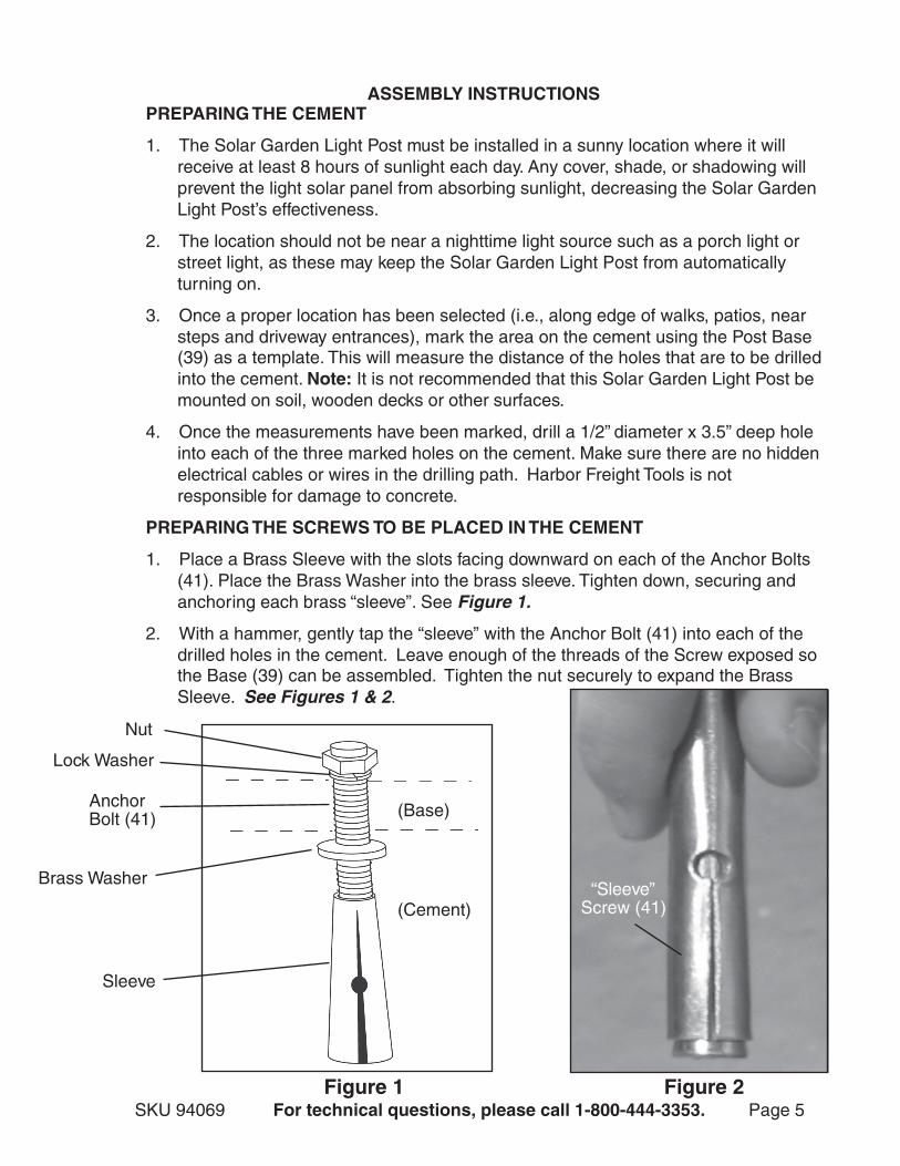
PREPARING THE SCREWS TO BE PLACED IN THE CEMENT
1. Place a Brass Sleeve with the slots facing downward on each of the Anchor Bolts(41). Place the Brass Washer into the brass sleeve. Tighten down, securing andanchoring each brass “sleeve”. See Figure 1.
2. With a hammer, gently tap the “sleeve” with the Anchor Bolt (41) into each of thedrilled holes in the cement. Leave enough of the threads of the Screw exposed sothe Base (39) can be assembled. Tighten the nut securely to expand the BrassSleeve. See Figures 1 & 2.
Brass Washer
AnchorBolt (41)
Lock Washer
Nut
Sleeve
Figure 1 Figure 2
“Sleeve”Screw (41)
(Base)
(Cement)

SKU 94069 For technical questions, please call 1-800-444-3353. Page 6
3. Fit the Base (39) over the three Screws (41) and secure with lock washers and nutsprovided. See Figure 1 on the previous page & Figure 3.
Figure 34. Fit the Middle Column (37) over the Base (39), matching up the holes. Secure with
three Hex Bolts (38). See Figure 4.
5. Thread the Top Column (36) to the Lamp Assembly. See Figure 5. Note: If thetop of the Lamp is not assembled, see Replacing the Batteries on page 8,item #5 and the assembly drawing on page 10.
LockWasher
Nut
Base (39)
Figure 4 Figure 5
MiddleColumn
(37)
Hex Bolt(38)
TopColumn
(36)
LampAssembly
Threads
SKU 94069 For technical questions, please call 1-800-444-3353. Page 7
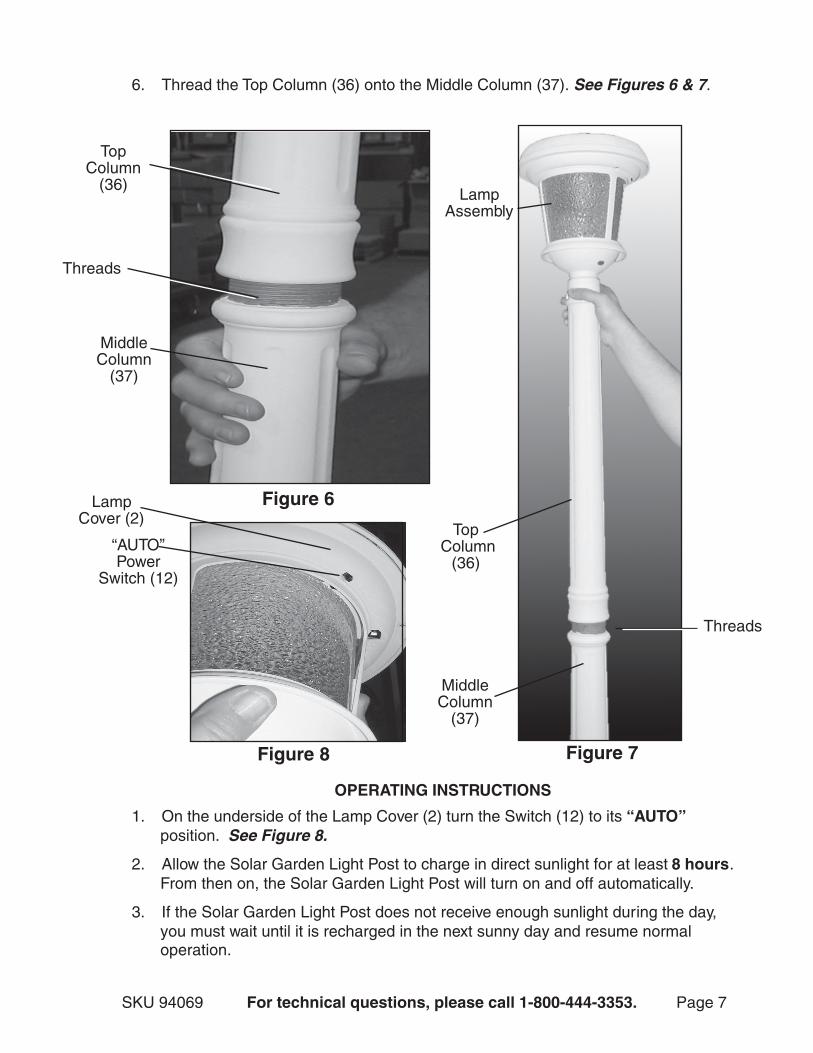
6. Thread the Top Column (36) onto the Middle Column (37). See Figures 6 & 7.
TopColumn
(36)
MiddleColumn
(37)
Threads
MiddleColumn
(37)
Figure 6
Figure 7
1. On the underside of the Lamp Cover (2) turn the Switch (12) to its “AUTO”position. See Figure 8.
2. Allow the Solar Garden Light Post to charge in direct sunlight for at least 8 hours.From then on, the Solar Garden Light Post will turn on and off automatically.
3. If the Solar Garden Light Post does not receive enough sunlight during the day,you must wait until it is recharged in the next sunny day and resume normaloperation.
OPERATING INSTRUCTIONS
Figure 8
“AUTO”Power
Switch (12)
LampCover (2)
Threads
Top Column
(36)
LampAssembly

SKU 94069 For technical questions, please call 1-800-444-3353. Page 8
REPLACING THE BATTERIES
1. On the underside of the Lamp Cover (2) turn the Switch (12) to its “OFF” position.See Figure 8 on previous page.
2. Unscrew the top light assembly from the Top Column (36). Remove the Lamp Cover(2) by unscrewing Screws (22) with a screwdriver (not provided). See Figure 9.Also, loosen the Upper Reflector (19) underneath by unscrewing Screws (17). Setscrews aside and gently move the Upper Reflector to one side, being careful not todamage the wires. See Figures 10 & 11.
3. Inside the Lamp Cover (2) are the battery compartments. Remove the Large andSmall Battery Compartment Lids (16 & 18). See Figure 11.
4. Replace old batteries with three new 1.2V NiCd “C” 2800 mAh Batteries (15). Notethe polarity position of the old Batteries, Positive (+) and Negative (–): Installthe new Batteries in the same position. Reattach the Battery Compartment Lids.See Figure 11. (Dispose of old batteries at your local waste disposal facility.)
5. Reassemble Reflector and top light unit and retighten the screws. This completesthe lamp assembly. Reattach to the Top Column (36). Turn the Switch (12) to “AUTO”.
Figure 9
Figure 10
Figure 11
Screw(22)
LampCover
(2)
Large BatteryCompartment
Lid (16)
Small BatteryCompartment
Lid (18)
Screw(17)
UpperReflector
(19)
REV 07/05

SKU 94069 For technical questions, please call 1-800-444-3353. Page 9
6. If there the days are excessively cloudy and dark, you may bring the top lampassembly indoors and recharge with a DC 6 Volt @300 MA maximum, AC adapter(not included). The connection for the charger is on the underside of the LampCover (2) next to the AUTO/OFF Switch (12). See Figure 12. Follow the directionsfor charging that are included with the charger. Harbor Freight Tool is notresponsible for damage due to recharging inaccurately.
AUTO/OFFSwitch (12)
AdapterConnection
Figure 12
MAINTENANCE
1. Inspect the Solar Panel (1) for damage. With a clean, soft cloth, or vacuum,remove all dirt and debris from the Solar Panel. Do not use solvents to wipe off theSolar Light assembly, as damage to the unit may result. If necessary, wipe with adamp cloth, using a mild detergent.
2. If you store the Solar Garden Light Post for more than two days, turn the PowerSwitch to its “OFF” position. For longer periods of storage, it should be rechargedonce every month. Otherwise remove batteries. But for best performance it shouldnot be stored for prolonged periods. Always store out of reach of children anduntrained users.
REV 07/05

SKU 94069 For technical questions, please call 1-800-444-3353. Page 10
REV 07/05

SKU 94069 For technical questions, please call 1-800-444-3353. Page 11
PARTS LIST
REV 07/05
traP noitpircseD yt'Q traP noitpircseD yt'Q1 lenaPraloS 1 22 8x4MwercS 4
2 revoCpmaL 1 32 revoCtroPgnigrahC 1
3 lenaPraloSrofpilCgnixiF 4 42 rotcelfeRmottoB 1
4 6x4MwercS 4 52 teSpilCssalG steS3
5 tekcarByrettaB 1 62 6x4MwercS 3
6 seriW&draoBtiucriC 1 72 ssalG 3
7 8x3MwercS 2 82 8x4MwercS 3
8 DELroftiucriC 21 92 esaBpmaL 1
9 tekcarBDEL 21 03 5.1x01MtuNxeH 2
01 DEL 21 13 rehsaW 2
11 tekcarBhctiwS 1 23 daerhTleetS 1
21 hctiwS 1 33 rotcennoC 1
31 troppuSgnigrahC 1 43 6x5MwercS 3
41 8x2MwercS 4 63 nmuloCpoT 1
51 )hAm0082(yrettaB"C"dCiN 3 73 nmuloCelddiM 1
61 diLtnemtrapmoCyrettaBegraL 1 83 81x6MtloBxeH 3
71 8x3MwercS 4 93 esaB 1
81 diLtnemtrapmoCyrettaBllamS 1 04 hcnerW 1
91 rotcelfeRreppU 1 14 L021x5.1x01MteStloBrohcnA steS3
02 emarFpmaL 1 24 8x4MwercS 4
12 revoChctiwS 1
PLEASE READ THE FOLLOWING CAREFULLY
THE MANUFACTURER AND/OR DISTRIBUTOR HAS PROVIDED THE PARTS DIAGRAM INTHIS MANUAL AS A REFERENCE TOOL ONLY. NEITHER THE MANUFACTURER NOR DISTRIBU-TOR MAKES ANY REPRESENTATION OR WARRANTY OF ANY KIND TO THE BUYER THAT HE ORSHE IS QUALIFIED TO MAKE ANY REPAIRS TO THE PRODUCT OR THAT HE OR SHE IS QUALI-FIED TO REPLACE ANY PARTS OF THE PRODUCT. IN FACT, THE MANUFACTURER AND/ORDISTRIBUTOR EXPRESSLY STATES THAT ALL REPAIRS AND PARTS REPLACEMENTS SHOULDBE UNDERTAKEN BY CERTIFIED AND LICENSED TECHNICIANS AND NOT BY THE BUYER. THEBUYER ASSUMES ALL RISK AND LIABILITY ARISING OUT OF HIS OR HER REPAIRS TO THEORIGINAL PRODUCT OR REPLACEMENT PARTS THERETO, OR ARISING OUT OF HIS OR HER
INSTALLATION OF REPLACEMENT PARTS THERETO.