9781137 371690 01 plms - macmillanihe.com · 13 internal division of space and integration of...
TRANSCRIPT

Contents
List of comparative studies and case studies v Acknowledgements vi Preface vii
PART 1 Preparing to build 1
1 Functions and requirements of industrial and commercial buildings 3 1.1 Physical and environmental functions of industrial and commercial buildings 4 1.2 Forces exerted on and by buildings 12 1.3 Structural behaviour of elements 17
2 The building process 28 2.1 Methods of building 29 2.2 Building sequence 41 2.3 Expenditure on building 54 2.4 Costs in use and life cycle costing 58 2.5 Building Information Modelling (BIM) by Dianne Marsh 60
3 Preparing to build 66 3.1 Site investigation and associated issues 67 3.2 Overview of statutory control of building 70 3.3 Ground water control 80
PART 2 Building substructure 91
4 Foundations 93 4.1 Soils and their characteristics 94 4.2 Functions of foundations and selection criteria 97 4.3 Shallow foundation forms 100 4.4 Deep foundation forms 108 4.5 Enhancing the sustainable credentials of foundations 118
5 Walls below ground and basement construction 123 5.1 Requirements of walls below ground 124 5.2 Options for waterproofing of basements 127 5.3 Methods of basement construction 132
6 Ground floors 148 6.1 Functions of ground floors and selection criteria 149
iii
6.2 Ground-supported floors 156 6.3 Suspended floors 165
PART 3 Building superstructure 169
7 High-rise buildings 171 7.1 Frames: functions and selection criteria 172 7.2 Frames: forms and materials 175 7.3 Comparative study 214
8 Long-span frames 221 8.1 Frames: functions and selection criteria 222 8.2 Frames and structures: forms and materials 223
9 Fire engineering design 246 9.1 Fire engineering design and the fire protection of structural elements 247
10 External walls and claddings for multi-storey and large-span commercial buildings 254
10.1 Functions of external walls and claddings 255 10.2 Options for walls and claddings to industrial and commercial buildings 260 10.3 Functions and selection criteria for claddings to low-rise buildings 270
11 Upper floors and internal access 284 11.1 Upper floor construction in multi-storey buildings 285 11.2 Internal access in multi-storey buildings 297 11.3 Floor finishes 305 11.4 Overview of mechanical transportation in buildings 310
12 Roof construction 323 12.1 Functions of roofs and selection criteria 324 12.2 Pitched roof forms 330 12.3 Flat roof forms 338 12.4 Roof drainage 357
13 Internal division of space and integration of services 361 13.1 Requirements of building services and the need for services integration 362 13.2 Structural and non-structural methods of services integration 368
PART 4 Sustainable building services 393
14 Sustainable engineering systems by Laurie Brady and Derek King 395 14.1 Mechanical engineering systems 396 14.2 Electrical engineering systems 404 14.3 Public health engineering systems 410
Index 425
iv Contents
1
PA
RT 1
3
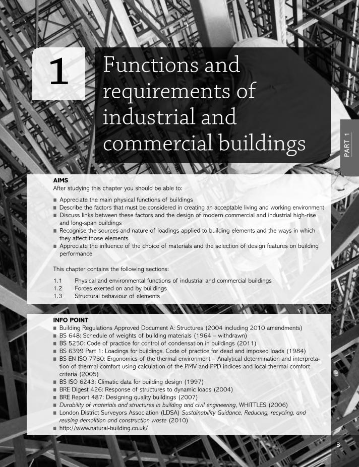
Functions and requirements of industrial and commercial buildings
AIMSAfter studying this chapter you should be able to:
n Appreciate the main physical functions of buildingsn Describe the factors that must be considered in creating an acceptable living and working environmentn Discuss links between these factors and the design of modern commercial and industrial high-rise
and long-span buildingsn Recognise the sources and nature of loadings applied to building elements and the ways in which
they affect those elementsn Appreciate the influence of the choice of materials and the selection of design features on building
performance
This chapter contains the following sections:
1.1 Physical and environmental functions of industrial and commercial buildings1.2 Forces exerted on and by buildings1.3 Structural behaviour of elements
INFO POINTn Building Regulations Approved Document A: Structures (2004 including 2010 amendments)n BS 648: Schedule of weights of building materials (1964 – withdrawn)n BS 5250: Code of practice for control of condensation in buildings (2011)n BS 6399 Part 1: Loadings for buildings. Code of practice for dead and imposed loads (1984)n BS EN ISO 7730: Ergonomics of the thermal environment – Analytical determination and interpreta-
tion of thermal comfort using calculation of the PMV and PPD indices and local thermal comfortcriteria (2005)
n BS ISO 6243: Climatic data for building design (1997)n BRE Digest 426: Response of structures to dynamic loads (2004)n BRE Report 487: Designing quality buildings (2007)n Durability of materials and structures in building and civil engineering, WHITTLES (2006)n London District Surveyors Association (LDSA) Sustainability Guidance, Reducing, recycling, and
reusing demolition and construction waste (2010)n http://www.natural-building.co.uk/
PA
RT 1
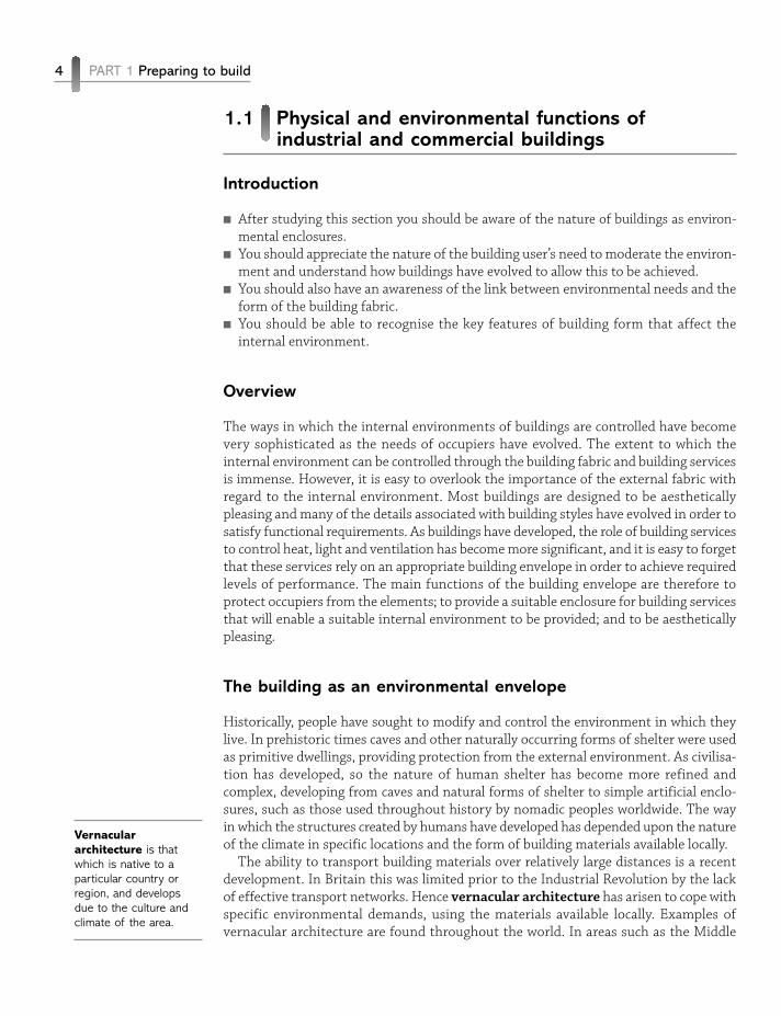
1.1 Physical and environmental functions ofindustrial and commercial buildings
Introduction
n After studying this section you should be aware of the nature of buildings as environ-mental enclosures.
n You should appreciate the nature of the building user’s need to moderate the environ-ment and understand how buildings have evolved to allow this to be achieved.
n You should also have an awareness of the link between environmental needs and theform of the building fabric.
n You should be able to recognise the key features of building form that affect theinternal environment.
Overview
The ways in which the internal environments of buildings are controlled have becomevery sophisticated as the needs of occupiers have evolved. The extent to which theinternal environment can be controlled through the building fabric and building servicesis immense. However, it is easy to overlook the importance of the external fabric withregard to the internal environment. Most buildings are designed to be aestheticallypleasing and many of the details associated with building styles have evolved in order tosatisfy functional requirements. As buildings have developed, the role of building servicesto control heat, light and ventilation has become more significant, and it is easy to forgetthat these services rely on an appropriate building envelope in order to achieve requiredlevels of performance. The main functions of the building envelope are therefore toprotect occupiers from the elements; to provide a suitable enclosure for building servicesthat will enable a suitable internal environment to be provided; and to be aestheticallypleasing.
The building as an environmental envelope
Historically, people have sought to modify and control the environment in which theylive. In prehistoric times caves and other naturally occurring forms of shelter were usedas primitive dwellings, providing protection from the external environment. As civilisa-tion has developed, so the nature of human shelter has become more refined andcomplex, developing from caves and natural forms of shelter to simple artificial enclo-sures, such as those used throughout history by nomadic peoples worldwide. The wayin which the structures created by humans have developed has depended upon the natureof the climate in specific locations and the form of building materials available locally.
The ability to transport building materials over relatively large distances is a recentdevelopment. In Britain this was limited prior to the Industrial Revolution by the lackof effective transport networks. Hence vernacular architecture has arisen to cope withspecific environmental demands, using the materials available locally. Examples ofvernacular architecture are found throughout the world. In areas such as the Middle
4 PART 1 Preparing to build
Vernaculararchitecture is thatwhich is native to aparticular country orregion, and developsdue to the culture andclimate of the area.

Eastern desert regions, where diurnal temperatures vary considerably, being very hotduring the day and cool at night, buildings of massive construction are common. Suchbuildings are referred to as ‘thermally heavy’ structures. The intense heat of the day ispartly reflected by the use of white surface finishes. That which is not reflected isabsorbed by the building fabric, rather than being transmitted into the occupied space.As a result of the slow thermal reaction of the building, this stored heat is released atthe times of day when the external temperatures may be very low, acting as a form ofstorage heater. The effects of direct solar gain are reduced by the use of a limited numberof small window openings. Conversely, in areas where the climate is consistently warmand humid, such as the Far East, a very different approach to building design is required.In such situations, rare breezes may be the only cooling medium which can remove theoppressive heat and humidity of the internal environment. Since this cooling and dehu-midifying effect takes place over a short period, the building must be able to react quicklyto maximise any potential benefit. Hence a thermally light structure is essential totransmit external changes to the interior with minimal delay. The nature of buildings insuch areas reflects these requirements, with lightweight building fabric and many largeopenings to allow cooling breezes to pass through the building. Figure 1.1 illustrates thediffering properties of thermally light buildings, with fast response to external changes,and thermally heavy buildings, which insulate the interior from external changes as aresult of slow reaction times.
The use of protective structures or enclosures is not the only method utilised in themoderation of the human environment. Since fire was first discovered and used by prim-itive people to provide light and heat, the use of energy to aid in environmental moder-ation has been fundamental. Although the use of built enclosures can moderate theinternal environment and reduce the effects of extremes in the external climate, theactive control and modification of the internal environment requires the input of energy.The use of buildings to house people, equipment and processes of differing types,exerting differing demands in terms of the internal environment, has resulted in the
Chapter 1 Functions and requirements of industrial and commercial buildings 5
PA
RT 1
Figure 1.1Differing properties of
thermally light andheavy buildings.

development of buildings and associated services capable of moderating the internalconditions within desired parameters with great accuracy.
The nature of people’s perception of comfort within buildings has also developed; thesimple exclusion of rain and protection from extreme cold or heat are no longer sufficientto meet human needs. The provision of an acceptable internal condition relies on anumber of factors, which may be summarised as follows:
n Thermal insulation and temperature controln Acoustic insulationn Provision of light (natural or artificial)n Control of humidityn Exclusion of contaminantsn Heat gain due to equipment such as photocopiers and computers.
Figure 1.2 illustrates these requirements and the ways in which they are met in modernconstruction forms.
6 PART 1 Preparing to build
Figure 1.2The building as an
environmental modifier.
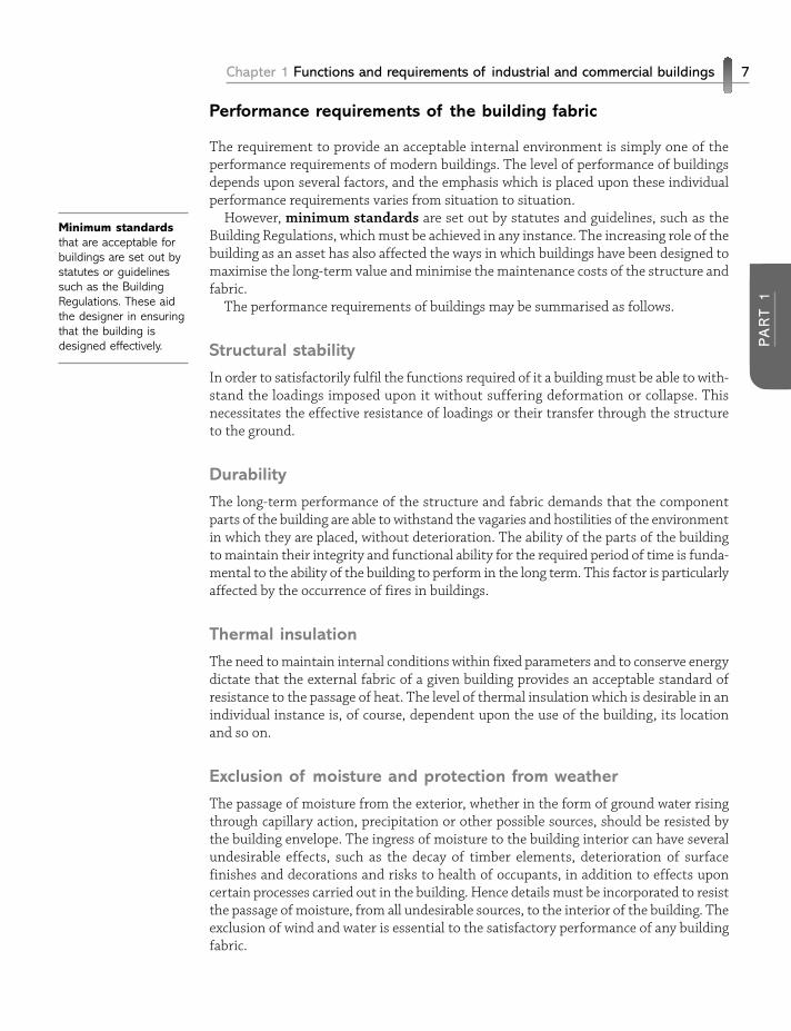
Performance requirements of the building fabric
The requirement to provide an acceptable internal environment is simply one of theperformance requirements of modern buildings. The level of performance of buildingsdepends upon several factors, and the emphasis which is placed upon these individualperformance requirements varies from situation to situation.
However, minimum standards are set out by statutes and guidelines, such as theBuilding Regulations, which must be achieved in any instance. The increasing role of thebuilding as an asset has also affected the ways in which buildings have been designed tomaximise the long-term value and minimise the maintenance costs of the structure andfabric.
The performance requirements of buildings may be summarised as follows.
Structural stability
In order to satisfactorily fulfil the functions required of it a building must be able to with-stand the loadings imposed upon it without suffering deformation or collapse. Thisnecessitates the effective resistance of loadings or their transfer through the structureto the ground.
Durability
The long-term performance of the structure and fabric demands that the componentparts of the building are able to withstand the vagaries and hostilities of the environmentin which they are placed, without deterioration. The ability of the parts of the buildingto maintain their integrity and functional ability for the required period of time is funda-mental to the ability of the building to perform in the long term. This factor is particularlyaffected by the occurrence of fires in buildings.
Thermal insulation
The need to maintain internal conditions within fixed parameters and to conserve energydictate that the external fabric of a given building provides an acceptable standard ofresistance to the passage of heat. The level of thermal insulation which is desirable in anindividual instance is, of course, dependent upon the use of the building, its locationand so on.
Exclusion of moisture and protection from weather
The passage of moisture from the exterior, whether in the form of ground water risingthrough capillary action, precipitation or other possible sources, should be resisted bythe building envelope. The ingress of moisture to the building interior can have severalundesirable effects, such as the decay of timber elements, deterioration of surfacefinishes and decorations and risks to health of occupants, in addition to effects uponcertain processes carried out in the building. Hence details must be incorporated to resistthe passage of moisture, from all undesirable sources, to the interior of the building. Theexclusion of wind and water is essential to the satisfactory performance of any buildingfabric.
Chapter 1 Functions and requirements of industrial and commercial buildings 7
PA
RT 1
Minimum standardsthat are acceptable forbuildings are set out bystatutes or guidelinessuch as the BuildingRegulations. These aidthe designer in ensuringthat the building isdesigned effectively.
Acoustic insulation
The passage of sound from the exterior to the interior, or between interior spaces, shouldbe considered in building construction. The level of sound transmission which is accept-able in a building will vary considerably, depending upon the nature of the use of thebuilding and its position.
Flexibility
In industrial and commercial buildings in particular, the ability of the building to copewith and respond to changing user needs has become very important. Hence the levelof required future flexibility must be taken into account in the initial design of thebuilding; this is reflected, for example, in the trend to create buildings with large openspaces, which may be subdivided by the use of partitions that may be readily removedand relocated.
Aesthetics
The issue of building aesthetics is subjective. However, it should be noted that in somesituations the importance of the building’s aesthetics is minimal, while in others, ofcourse, it is highly important.
For example, the appearance of a unit on an industrial estate is far less important thanthat of a city centre municipal building. The extent to which aesthetics are pursued willhave an inevitable effect on the cost of the building.
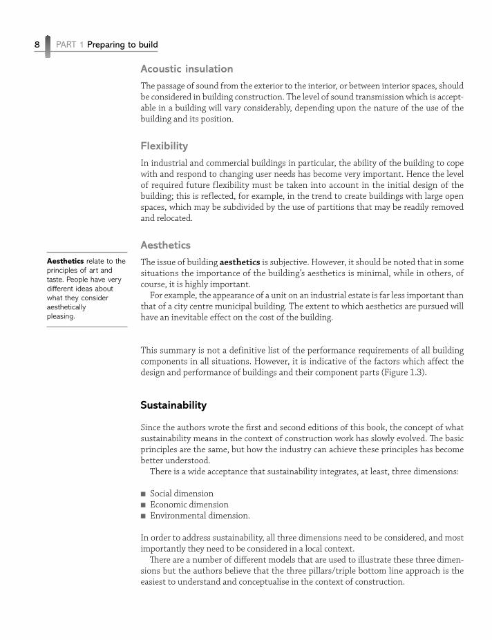
This summary is not a definitive list of the performance requirements of all buildingcomponents in all situations. However, it is indicative of the factors which affect thedesign and performance of buildings and their component parts (Figure 1.3).
Sustainability
Since the authors wrote the first and second editions of this book, the concept of whatsustainability means in the context of construction work has slowly evolved. The basicprinciples are the same, but how the industry can achieve these principles has becomebetter understood.
There is a wide acceptance that sustainability integrates, at least, three dimensions:
n Social dimensionn Economic dimensionn Environmental dimension.
In order to address sustainability, all three dimensions need to be considered, and mostimportantly they need to be considered in a local context.
There are a number of different models that are used to illustrate these three dimen-sions but the authors believe that the three pillars/triple bottom line approach is theeasiest to understand and conceptualise in the context of construction.
8 PART 1 Preparing to build
Aesthetics relate to theprinciples of art andtaste. People have verydifferent ideas aboutwhat they consideraesthetically pleasing.
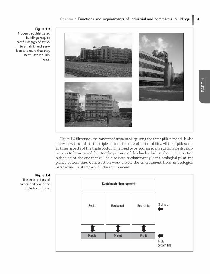
Figure 1.4 illustrates the concept of sustainability using the three pillars model. It alsoshows how this links to the triple bottom line view of sustainability. All three pillars andall three aspects of the triple bottom line need to be addressed if a sustainable develop-ment is to be achieved, but for the purpose of this book which is about constructiontechnologies, the one that will be discussed predominantly is the ecological pillar andplanet bottom line. Construction work affects the environment from an ecologicalperspective, i.e. it impacts on the environment.
Chapter 1 Functions and requirements of industrial and commercial buildings 9
PA
RT 1
Figure 1.3Modern, sophisticated
buildings requirecareful design of struc-
ture, fabric and serv-ices to ensure that they
meet user require-ments.
Figure 1.4The three pillars of
sustainability and thetriple bottom line.
Sustainable development
Social Ecological
Planet ProfitPeople
Economic 3 pillars
Triplebottom line
Impact of construction work and buildings on the environment
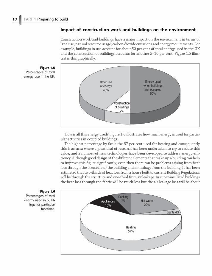
Construction work and buildings have a major impact on the environment in terms ofland use, natural resource usage, carbon dioxideemissions and energy requirements. Forexample, buildings in use account for about 50 per cent of total energy used in the UKand the construction of buildings accounts for another 5–10 per cent. Figure 1.5 illus-trates this graphically.
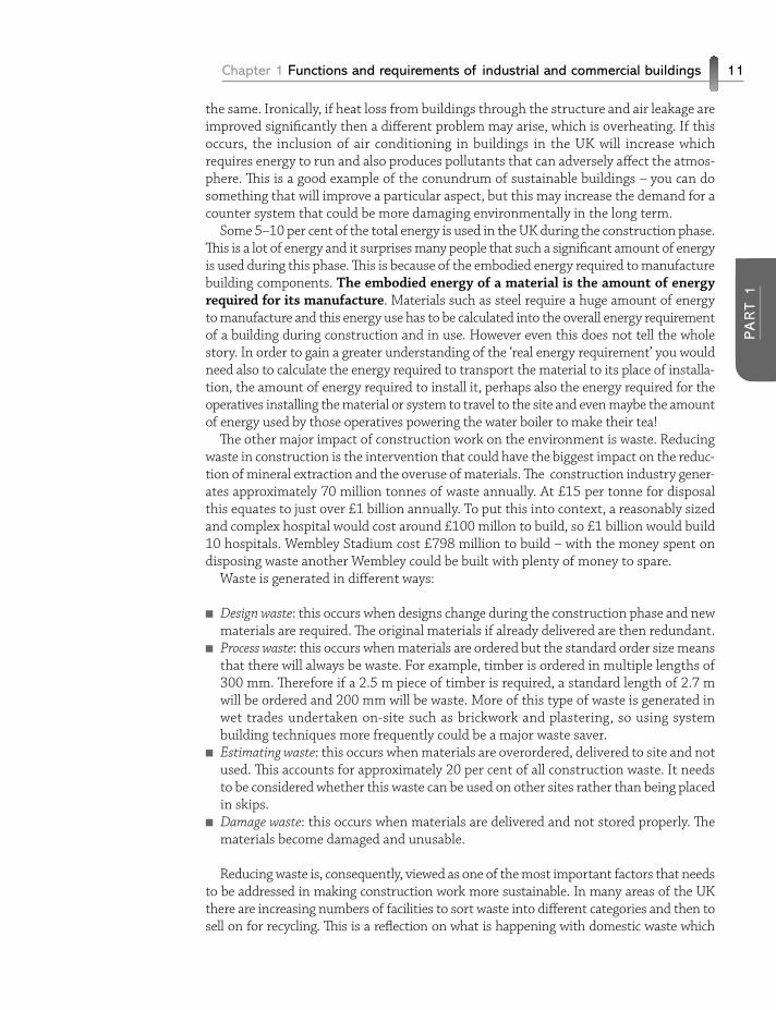
How is all this energy used? Figure 1.6 illustrates how much energy is used for partic-ular activities in occupied buildings.
The highest percentage by far is the 57 per cent used for heating and consequentlythis is an area where a great deal of research has been undertaken to try to reduce thisvalue, and a number of new technologies have been developed to address energy effi-ciency. Although good design of the different elements that make up a building can helpto improve this figure significantly, even then there can be problems arising from heatloss through the structure of the building and air leakage from the building. It has beenestimated that two-thirds of heat loss from a house built to current Building Regulationswill be through the structure and one-third from air leakage. In super-insulated buildingsthe heat loss through the fabric will be much less but the air leakage loss will be about
10 PART 1 Preparing to build
Figure 1.5Percentages of total
energy use in the UK.
Energy usedwhen buildingsare occupied
50%
Other useof energy
43%
Constructionof buildings
7%
Figure 1.6Percentages of total
energy used in build-ings for particular
functions.
Hot water22%
Cooking7%
Lights 4%
Appliances10%
Heating57%
Chapter 1 Functions and requirements of industrial and commercial buildings 11
PA
RT 1
the same. Ironically, if heat loss from buildings through the structure and air leakage areimproved significantly then a different problem may arise, which is overheating. If thisoccurs, the inclusion of air conditioning in buildings in the UK will increase whichrequires energy to run and also produces pollutants that can adversely affect the atmos-phere. This is a good example of the conundrum of sustainable buildings – you can dosomething that will improve a particular aspect, but this may increase the demand for acounter system that could be more damaging environmentally in the long term.
Some 5–10 per cent of the total energy is used in the UK during the construction phase.This is a lot of energy and it surprises many people that such a significant amount of energyis used during this phase. This is because of the embodied energy required to manufacturebuilding components. The embodied energy of a material is the amount of energyrequired for its manufacture. Materials such as steel require a huge amount of energyto manufacture and this energy use has to be calculated into the overall energy requirementof a building during construction and in use. However even this does not tell the wholestory. In order to gain a greater understanding of the ‘real energy requirement’ you wouldneed also to calculate the energy required to transport the material to its place of installa-tion, the amount of energy required to install it, perhaps also the energy required for theoperatives installing the material or system to travel to the site and even maybe the amountof energy used by those operatives powering the water boiler to make their tea!
The other major impact of construction work on the environment is waste. Reducingwaste in construction is the intervention that could have the biggest impact on the reduc-tion of mineral extraction and the overuse of materials. The construction industry gener-ates approximately 70 million tonnes of waste annually. At £15 per tonne for disposalthis equates to just over £1 billion annually. To put this into context, a reasonably sizedand complex hospital would cost around £100 millon to build, so £1 billion would build10 hospitals. Wembley Stadium cost £798 million to build – with the money spent ondisposing waste another Wembley could be built with plenty of money to spare.
Waste is generated in different ways:
n Design waste: this occurs when designs change during the construction phase and newmaterials are required. The original materials if already delivered are then redundant.
n Process waste: this occurs when materials are ordered but the standard order size meansthat there will always be waste. For example, timber is ordered in multiple lengths of300 mm. Therefore if a 2.5 m piece of timber is required, a standard length of 2.7 mwill be ordered and 200 mm will be waste. More of this type of waste is generated inwet trades undertaken on-site such as brickwork and plastering, so using systembuilding techniques more frequently could be a major waste saver.
n Estimating waste: this occurs when materials are overordered, delivered to site and notused. This accounts for approximately 20 per cent of all construction waste. It needsto be considered whether this waste can be used on other sites rather than being placedin skips.
n Damage waste: this occurs when materials are delivered and not stored properly. Thematerials become damaged and unusable.
Reducing waste is, consequently, viewed as one of the most important factors that needsto be addressed in making construction work more sustainable. In many areas of the UKthere are increasing numbers of facilities to sort waste into different categories and then tosell on for recycling. This is a reflection on what is happening with domestic waste which
many Local Authorities require to be sorted into recyclable and non-recyclable bins. Thetypes of materials that are recyclable are growing. However, this needs to be managed care-fully on-site as different skips/bins can easily become contaminated if the wrong materialsare placed in them. Demolition industry contractors already have an excellent record forrecycling waste (over 90 per cent of demolition ‘waste’ was reused or recycled in 2005–06 –NFDC figures). However, to date, the construction industry as a whole has paid less attentionto the possibilities of recycling, reuse and reclaiming of materials, but this has to change.
In this third edition of Construction Technology 2, technologies that have been devel-oped to reduce mineral extraction, increase energy and reduce waste are introduced inthe relevant chapters. Some of the technologies, such as timber framing for multi-storeybuildings to reduce the need for steel and concrete and the use of MMC techniques toreduce waste, were included in the previous editions, but the growing acceptance of thesetechniques as more ‘sustainable’ practices is emphasised further. In addition, construc-tion technologies that could be badged as ‘green’ are integrated into chapters. The authorsbelieve that by integrating these green technologies as opposed to having a ‘green tech-nologies’ chapter, their choice as potentially realistic solutions will be better evidenced.If these technologies are dealt with separately then potentially they will only be usedwhen a building is required to be show-cased as being green. This approach leads totokenism rather than a holistic view of the building from a sustainable perspective.
REFLECTIVE SUMMARYWith reference to the building as an environmental shelter, remember:
n Heat needs to be preserved, while allowing light into a building.n Thermally heavy structures tend to be heavy and intercept heat by absorption.n Aesthetics of buildings are very subjective and will depend very much on the
nature and location of a building.n A large amount of heat is generated by equipment in industrial and commercial
buildings, and this needs to be seriously considered in the design of these types ofbuilding.
n The increasing recognition of the impact of construction on the environment hasled to a recognition of sustainability as a core function of building.
REVIEW TASKn What are the advantages of thermally light buildings and thermally heavy buildings
with regard to the performance requirements of multi-storey buildings?n Visit the companion website at www.palgrave.com/engineering/riley2 to view
sample outline answers to the review task.
1.2 Forces exerted on and by buildings
Introduction
n After studying this section you should be aware of the forces that act upon the struc-ture of a building.
12 PART 1 Preparing to build
n You should have developed a knowledge of the origins of these forces and the ways inwhich they act upon the structural elements of a building.
n You should also have an intuitive knowledge of the magnitude of the different forcesand be able to distinguish between the forces acting on a building and the forcesexerted by it.
Overview
The forces applied to buildings derive from a variety of sources and act in many differentways. However, a number of basic principles of structural behaviour can be consideredto encompass all of these applications and effects. The ways in which the structure andfabric of a building behave will depend upon their ability to cope with the inherent andapplied loadings. If the building is able to withstand the loadings imposed upon it, it willremain static – in such a state it is considered to be stable. Any force acting upon abuilding must be considered as a loading, whether it be from the actions of wind on thebuilding, the positioning of furniture, equipment or people, or simply the effect of theself-weight of the structure.
In order to withstand such forces two basic structural properties must be provided bythe building:
n The component parts of the building must possess adequate strength to carryapplied loads.
n Applied forces must be balanced, to resist the tendency for the building tomove. That is, the structure must be in equilibrium.
The forces, or loadings, applied to buildings can be considered under two generic clas-sifications, dead loads and live loads. Dead loads would normally include the self-weightof the structure, including floors, walls, roofs, finishes, services and so on. Live loadswould include loadings applied to the building in use, such as the weight of people, furni-ture, machinery and wind loadings. Such loadings are normally considered as acting posi-tively on the building; however, in the case of wind loadings, suction zones may becreated, i.e. negative loadings; this effect is often illustrated by the action of roofs beinglifted from buildings in high wind conditions. Hence buildings must be designed to copewith forces acting in a variety of ways.
The ability of the materials used in the construction of buildings to withstand theseloadings is termed strength. In considering whether a building has sufficient strength,the nature of loadings must be considered.
Stress
When subjected to forces, all structural elements tend to deform, and this deformationis resisted by stresses, or internal forces within the element. If these stresses do notexceed the level which can be satisfactorily withstood by the material then the buildingwill remain structurally sound.
Chapter 1 Functions and requirements of industrial and commercial buildings 13
PA
RT 1
Types of stress
The formula used to calculate stress is W/A, where W = load and A = cross-sectional area,and stress is measured in N/mm2 or kN/m2.
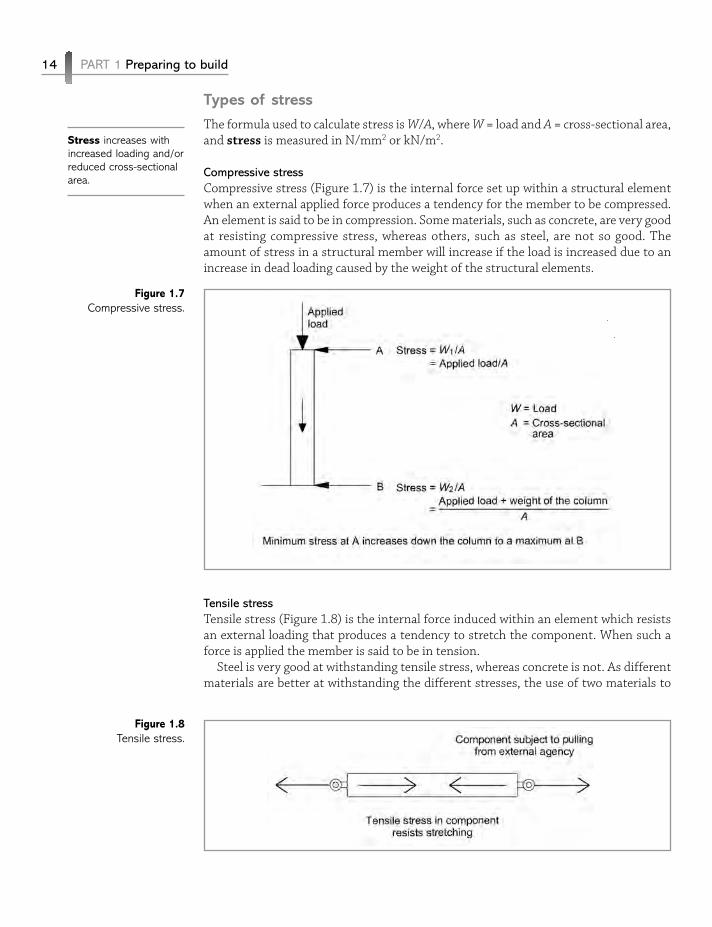
Compressive stress
Compressive stress (Figure 1.7) is the internal force set up within a structural elementwhen an external applied force produces a tendency for the member to be compressed.An element is said to be in compression. Some materials, such as concrete, are very goodat resisting compressive stress, whereas others, such as steel, are not so good. Theamount of stress in a structural member will increase if the load is increased due to anincrease in dead loading caused by the weight of the structural elements.
Tensile stress
Tensile stress (Figure 1.8) is the internal force induced within an element which resistsan external loading that produces a tendency to stretch the component. When such aforce is applied the member is said to be in tension.
Steel is very good at withstanding tensile stress, whereas concrete is not. As differentmaterials are better at withstanding the different stresses, the use of two materials to
14 PART 1 Preparing to build
Figure 1.7Compressive stress.
Figure 1.8Tensile stress.
Stress increases withincreased loading and/orreduced cross-sectionalarea.
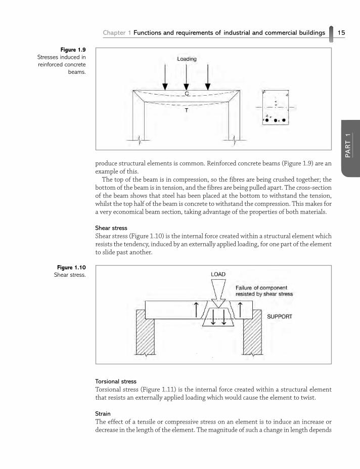
produce structural elements is common. Reinforced concrete beams (Figure 1.9) are anexample of this.
The top of the beam is in compression, so the fibres are being crushed together; thebottom of the beam is in tension, and the fibres are being pulled apart. The cross-sectionof the beam shows that steel has been placed at the bottom to withstand the tension,whilst the top half of the beam is concrete to withstand the compression. This makes fora very economical beam section, taking advantage of the properties of both materials.
Shear stress
Shear stress (Figure 1.10) is the internal force created within a structural element whichresists the tendency, induced by an externally applied loading, for one part of the elementto slide past another.
Torsional stress
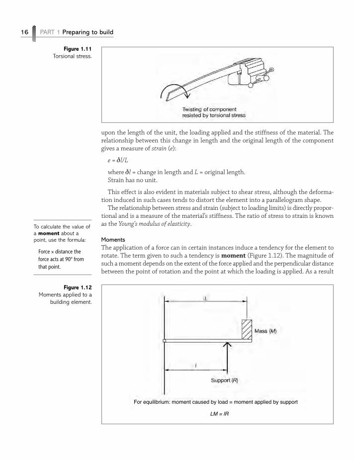
Torsional stress (Figure 1.11) is the internal force created within a structural elementthat resists an externally applied loading which would cause the element to twist.
Strain
The effect of a tensile or compressive stress on an element is to induce an increase ordecrease in the length of the element. The magnitude of such a change in length depends
Chapter 1 Functions and requirements of industrial and commercial buildings 15
PA
RT 1
Figure 1.9Stresses induced inreinforced concrete
beams.
Figure 1.10Shear stress.
upon the length of the unit, the loading applied and the stiffness of the material. Therelationship between this change in length and the original length of the componentgives a measure of strain (e):
e = δl/L
where δl = change in length and L = original length.Strain has no unit.
This effect is also evident in materials subject to shear stress, although the deforma-tion induced in such cases tends to distort the element into a parallelogram shape.
The relationship between stress and strain (subject to loading limits) is directly propor-tional and is a measure of the material’s stiffness. The ratio of stress to strain is knownas the Young’s modulus of elasticity.
Moments
The application of a force can in certain instances induce a tendency for the element torotate. The term given to such a tendency is moment (Figure 1.12). The magnitude ofsuch a moment depends on the extent of the force applied and the perpendicular distancebetween the point of rotation and the point at which the loading is applied. As a result
16 PART 1 Preparing to build
Figure 1.11Torsional stress.
To calculate the value ofa moment about apoint, use the formula:
Force × distance theforce acts at 90° fromthat point.
Figure 1.12Moments applied to a
building element.
For equilibrium: moment caused by load = moment applied by support
LM = lR
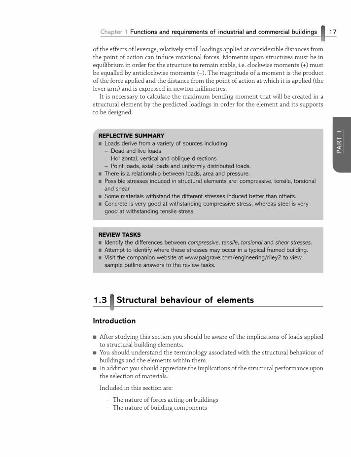
of the effects of leverage, relatively small loadings applied at considerable distances fromthe point of action can induce rotational forces. Moments upon structures must be inequilibrium in order for the structure to remain stable, i.e. clockwise moments (+) mustbe equalled by anticlockwise moments (–). The magnitude of a moment is the productof the force applied and the distance from the point of action at which it is applied (thelever arm) and is expressed in newton millimetres.
It is necessary to calculate the maximum bending moment that will be created in astructural element by the predicted loadings in order for the element and its supportsto be designed.
REFLECTIVE SUMMARYn Loads derive from a variety of sources including:
– Dead and live loads– Horizontal, vertical and oblique directions– Point loads, axial loads and uniformly distributed loads.
n There is a relationship between loads, area and pressure.n Possible stresses induced in structural elements are: compressive, tensile, torsional
and shear.n Some materials withstand the different stresses induced better than others.n Concrete is very good at withstanding compressive stress, whereas steel is very
good at withstanding tensile stress.
REVIEW TASKSn Identify the differences between compressive, tensile, torsional and shear stresses.n Attempt to identify where these stresses may occur in a typical framed building.n Visit the companion website at www.palgrave.com/engineering/riley2 to view
sample outline answers to the review tasks.
1.3 Structural behaviour of elements
Introduction
n After studying this section you should be aware of the implications of loads appliedto structural building elements.
n You should understand the terminology associated with the structural behaviour ofbuildings and the elements within them.
n In addition you should appreciate the implications of the structural performance uponthe selection of materials.
Included in this section are:
– The nature of forces acting on buildings– The nature of building components
Chapter 1 Functions and requirements of industrial and commercial buildings 17
PA
RT 1
Overview
The effects of the types of loadings or forces exerted on a building depend on the way inwhich those forces are applied. Maintaining the integrity and structural stability of abuilding relies on its ability to withstand inherent and applied loadings without sufferingmovement or deformation, although it is possible to allow for a limited amount of move-ment or deformation within the building design, as is common in mining areas, forexample. Resistance to movement and deformation results from effective initial designof the structure as a unit and the ability of materials used for individual components toperform adequately.
Limited movement, of certain types, is inevitable in all structures and must be accom-modated to prevent the occurrence of serious structural defects. The effects of thermaland moisture-induced changes in building materials can be substantial, producing cyclicalvariations in the size of components. This dictates the inclusion of specific movementaccommodation details, particularly when dealing with elements of great size, such assolid floors of large area. Additionally, the period shortly following the erection of abuilding often results in the minor consolidation of the ground upon which it is located;this will generally be very minor in nature however. These forms of movement and defor-mation are acceptable but other forms must be avoided, their nature and extentdepending upon the nature and direction of the applied forces. Three main categories ofapplied forces combine to give rise to all types of building movement.
The nature of forces acting on buildings
Vertical forces
Vertically applied forces, such as the dead loading of the building structure and some liveloadings, act to give rise to a tendency for the structure to move in a downward direction,i.e. to sink into the ground. The extent of any such movement depends upon the abilityof the building to spread the building loads over a sufficient area to ensure stability onground of a given loadbearing capacity. The loadbearing capacities of different soil typesvary considerably, and the function of foundations to buildings is to ensure that thebearing capacity of the ground is not exceeded by the loading of the structure. In mostinstances the bearing capacity of the ground, normally expressed in kN/m2 , is very muchless than the pressures likely to be exerted by the building structure if placed directlyonto the ground. The pressure is reduced by utilising foundations to increase the inter-face area between the building and the ground (foundation design), thus reducing thepressure applied to the ground (Figure 1.13).
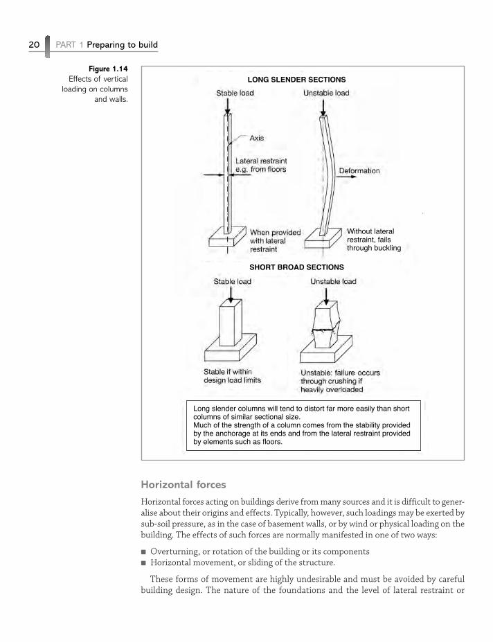
The need to withstand such vertical loadings is not exclusive to the lower elements ofthe building structure, although such loadings are greater in magnitude at the lowersections due to the effects of accumulated loadings from the structure. All structuralcomponents must be of sufficient size and strength to carry loadings imposed uponthem without failure or deformation. Columns and walls, often carrying the loads offloors, roofs and so on from above, must resist the tendency to buckle or to be crushedby the forces exerted (Figure 1.14). The way in which columns and walls perform underthe effects of vertical loadings depends on the slenderness ratio of the component. Insimple terms, long, slender units will tend to buckle easily, whilst short, broad units will
18 PART 1 Preparing to build
Foundation designutilises the sameprinciples as stresscalculation. Increasedloading will increase thestress induced in thesoil, but increasing thecross-sectional area willreduce this stress.

resist such tendencies. In long, thin components the risk of buckling can be greatlyreduced by incorporating bracing to prevent sideways movement; this is termed lateralrestraint.
If overloaded significantly, even short, broad sections may be subject to failure; in suchinstances the mode of failure tends to be crushing of the unit, although this is compar-atively rare.
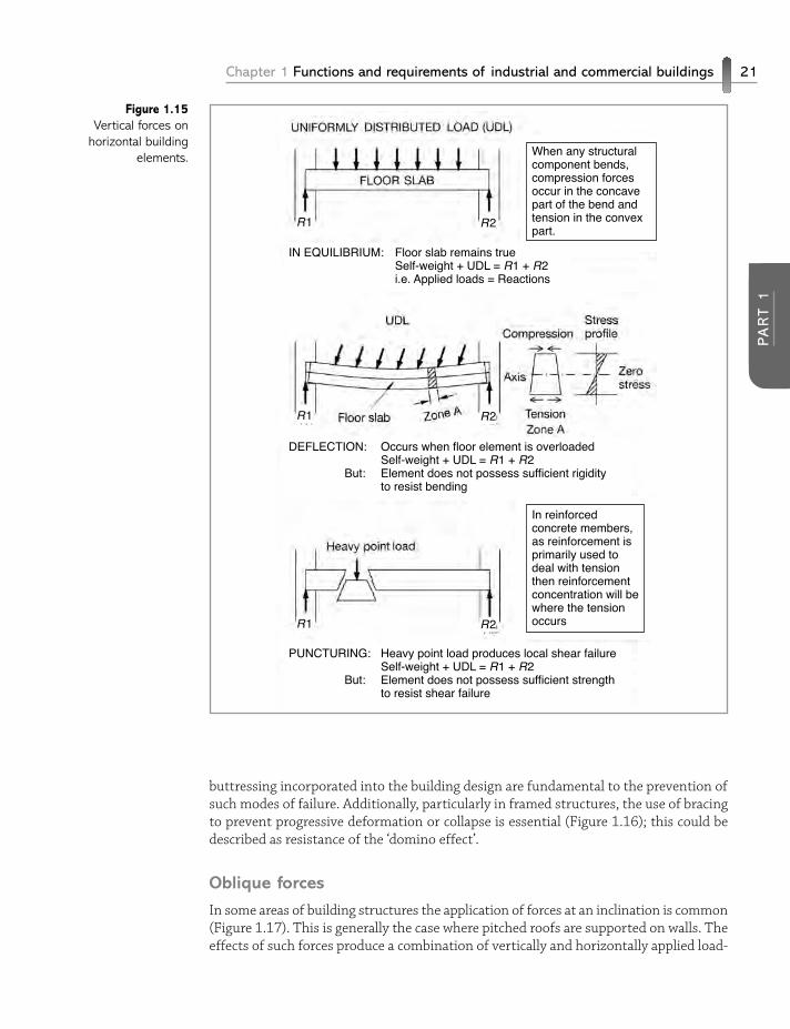
Horizontal components, such as floors and beams, must also be capable of performingeffectively while withstanding vertically applied loadings (Figure 1.15). This is ensuredby the use of materials of sufficient strength, designed in an appropriate manner, withsufficient support to maintain stability. Heavy loadings on such components may giverise to deflection resulting from the establishment of moments, or in extreme casespuncturing of the component resulting from excessive shear at a specific point. Whensubjected to deflection, beam and floor sections are forced into compression at the upperregions and tension at the lower regions. This may limit the design feasibility of somematerials, such as concrete, which performs well in compression but not in tension.Hence the use of composite units is common, such as concrete reinforced in the tensionzones with steel.
Vertical forces applied to buildings may also be in an upward direction. These mustbe resisted, usually by making the best use of the mass of the building. Upward loadingsmay be generated from the ground, as in zones of shrinkable clay or soils that are proneto expansion due to frost, for example. The upward force exerted by the ground in suchcases is termed heave.
Chapter 1 Functions and requirements of industrial and commercial buildings 19
PA
RT 1
Figure 1.13Reduction of pressureapplied to the groundresulting from the use
of foundations.
Area = 0.215 m2 Area = 0.450 m2
P = L /A = 10/0.215 P = L /A = 10/0.450
= 46.5 kN/m2 = 22.2 kN/m2
P = pressure on soil
Pressure applied to the ground is a function of load (L) and area (A).
By increasing the contact area by using foundations, the pressure can be controlled.
Deflection of structuralelements is allowablewithin given limits.Excessive deflection canlead to failure, but amore common problemis deflection to a levelthat produces unsightlycracking.
Horizontal forces
Horizontal forces acting on buildings derive from many sources and it is difficult to gener-alise about their origins and effects. Typically, however, such loadings may be exerted bysub-soil pressure, as in the case of basement walls, or by wind or physical loading on thebuilding. The effects of such forces are normally manifested in one of two ways:
n Overturning, or rotation of the building or its componentsn Horizontal movement, or sliding of the structure.
These forms of movement are highly undesirable and must be avoided by carefulbuilding design. The nature of the foundations and the level of lateral restraint or
20 PART 1 Preparing to build
Figure 1.14Effects of vertical
loading on columnsand walls.
Without lateralrestraint, failsthrough buckling
SHORT BROAD SECTIONS
LONG SLENDER SECTIONS
Long slender columns will tend to distort far more easily than shortcolumns of similar sectional size.Much of the strength of a column comes from the stability providedby the anchorage at its ends and from the lateral restraint providedby elements such as floors.
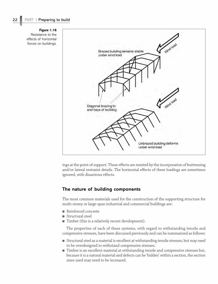
buttressing incorporated into the building design are fundamental to the prevention ofsuch modes of failure. Additionally, particularly in framed structures, the use of bracingto prevent progressive deformation or collapse is essential (Figure 1.16); this could bedescribed as resistance of the ‘domino effect’.
Oblique forces
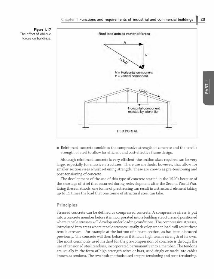
In some areas of building structures the application of forces at an inclination is common(Figure 1.17). This is generally the case where pitched roofs are supported on walls. Theeffects of such forces produce a combination of vertically and horizontally applied load-
Chapter 1 Functions and requirements of industrial and commercial buildings 21
PA
RT 1
Figure 1.15Vertical forces on
horizontal buildingelements.
R1 R2
R1 R2
R1 R2
IN EQUILIBRIUM: Floor slab remains true Self-weight + UDL = R1 + R2 i.e. Applied loads = Reactions
DEFLECTION: Occurs when floor element is overloaded Self-weight + UDL = R1 + R2 But: Element does not possess sufficient rigidity to resist bending
When any structuralcomponent bends,compression forcesoccur in the concavepart of the bend andtension in the convexpart.
In reinforcedconcrete members,as reinforcement isprimarily used todeal with tensionthen reinforcementconcentration will bewhere the tensionoccurs
PUNCTURING: Heavy point load produces local shear failure Self-weight + UDL = R1 + R2 But: Element does not possess sufficient strength to resist shear failure
ings at the point of support. These effects are resisted by the incorporation of buttressingand/or lateral restraint details. The horizontal effects of these loadings are sometimesignored, with disastrous effects.
The nature of building components
The most common materials used for the construction of the supporting structure formulti-storey or large-span industrial and commercial buildings are:
n Reinforced concreten Structural steeln Timber (this is a relatively recent development).
The properties of each of these systems, with regard to withstanding tensile andcompressive stresses, have been discussed previously and can be summarised as follows:
n Structural steel as a material is excellent at withstanding tensile stresses, but may needto be overdesigned to withstand compressive stresses.
n Timber is an excellent material at withstanding tensile and compressive stresses but,because it is a natural material and defects can be ‘hidden’ within a section, the sectionsizes used may need to be increased.
22 PART 1 Preparing to build
Figure 1.16Resistance to the
effects of horizontalforces on buildings.
n Reinforced concrete combines the compressive strength of concrete and the tensilestrength of steel to allow for efficient and cost-effective frame design.
Although reinforced concrete is very efficient, the section sizes required can be verylarge, especially for massive structures. There are methods, however, that allow forsmaller section sizes whilst retaining strength. These are known as pre-tensioning andpost-tensioning of concrete.
The development of the use of this type of concrete started in the 1940s because ofthe shortage of steel that occurred during redevelopment after the Second World War.Using these methods, one tonne of prestressing can result in a structural element takingup to 15 times the load that one tonne of structural steel can take.
Principles
Stressed concrete can be defined as compressed concrete. A compressive stress is putinto a concrete member before it is incorporated into a building structure and positionedwhere tensile stresses will develop under loading conditions. The compressive stresses,introduced into areas where tensile stresses usually develop under load, will resist thesetensile stresses – for example at the bottom of a beam section, as has been discussedpreviously. The concrete will then behave as if it had a high tensile strength of its own.The most commonly used method for the pre-compression of concrete is through theuse of tensioned steel tendons, incorporated permanently into a member. The tendonsare usually in the form of high-strength wires or bars, used singly or made into cablesknown as tendons. The two basic methods used are pre-tensioning and post-tensioning.
Chapter 1 Functions and requirements of industrial and commercial buildings 23
PA
RT 1
Figure 1.17The effect of oblique
forces on buildings.
Pre-tensioning
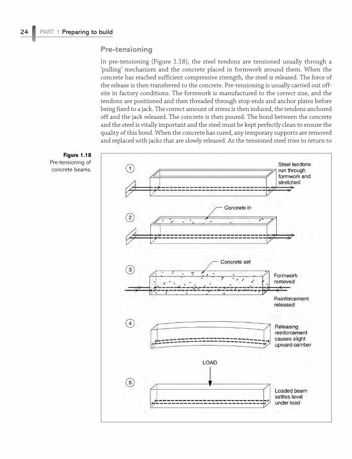
In pre-tensioning (Figure 1.18), the steel tendons are tensioned usually through a‘pulling’ mechanism and the concrete placed in formwork around them. When theconcrete has reached sufficient compressive strength, the steel is released. The force ofthe release is then transferred to the concrete. Pre-tensioning is usually carried out off-site in factory conditions. The formwork is manufactured to the correct size, and thetendons are positioned and then threaded through stop ends and anchor plates beforebeing fixed to a jack. The correct amount of stress is then induced, the tendons anchoredoff and the jack released. The concrete is then poured. The bond between the concreteand the steel is vitally important and the steel must be kept perfectly clean to ensure thequality of this bond. When the concrete has cured, any temporary supports are removedand replaced with jacks that are slowly released. As the tensioned steel tries to return to
24 PART 1 Preparing to build
Figure 1.18Pre-tensioning ofconcrete beams.
its original shape the bond between the concrete and steel will resist this and the concreteis placed in compression.
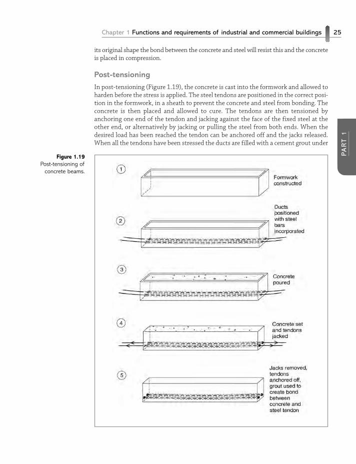
Post-tensioning
In post-tensioning (Figure 1.19), the concrete is cast into the formwork and allowed toharden before the stress is applied. The steel tendons are positioned in the correct posi-tion in the formwork, in a sheath to prevent the concrete and steel from bonding. Theconcrete is then placed and allowed to cure. The tendons are then tensioned byanchoring one end of the tendon and jacking against the face of the fixed steel at theother end, or alternatively by jacking or pulling the steel from both ends. When thedesired load has been reached the tendon can be anchored off and the jacks released.When all the tendons have been stressed the ducts are filled with a cement grout under
Chapter 1 Functions and requirements of industrial and commercial buildings 25
PA
RT 1
Figure 1.19Post-tensioning of
concrete beams.
pressure. This grout prevents steel corrosion and creates a bond between the concreteand the tendon.
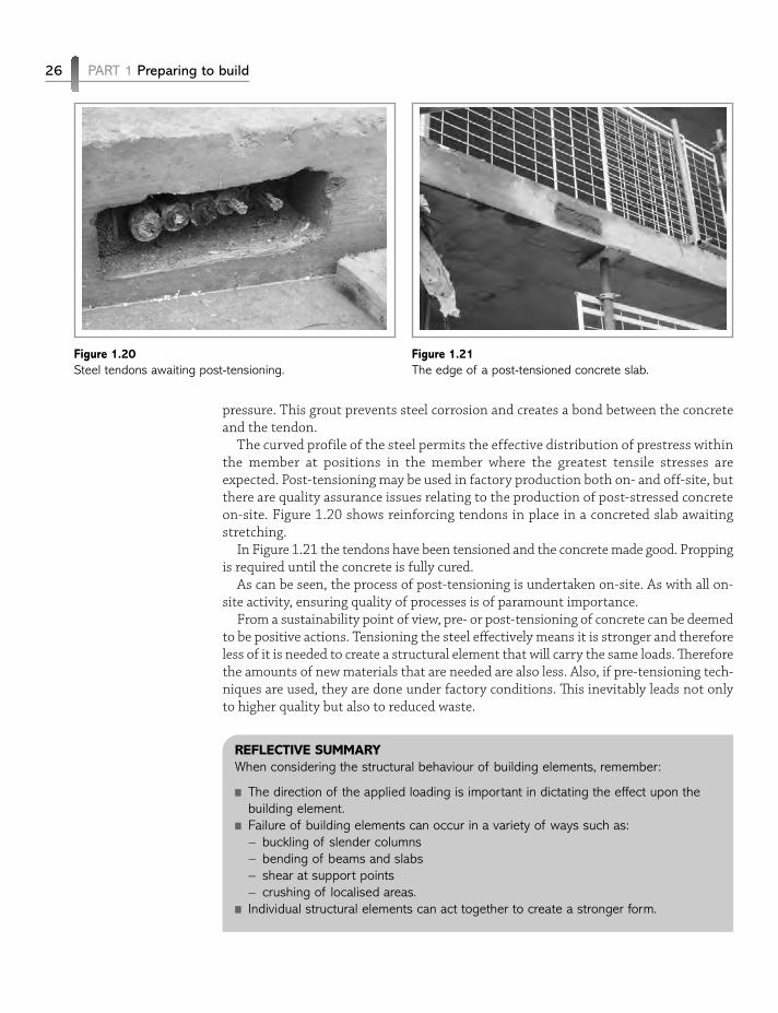
The curved profile of the steel permits the effective distribution of prestress withinthe member at positions in the member where the greatest tensile stresses areexpected. Post-tensioning may be used in factory production both on- and off-site, butthere are quality assurance issues relating to the production of post-stressed concreteon-site. Figure 1.20 shows reinforcing tendons in place in a concreted slab awaitingstretching.
In Figure 1.21 the tendons have been tensioned and the concrete made good. Proppingis required until the concrete is fully cured.
As can be seen, the process of post-tensioning is undertaken on-site. As with all on-site activity, ensuring quality of processes is of paramount importance.
From a sustainability point of view, pre- or post-tensioning of concrete can be deemedto be positive actions. Tensioning the steel effectively means it is stronger and thereforeless of it is needed to create a structural element that will carry the same loads. Thereforethe amounts of new materials that are needed are also less. Also, if pre-tensioning tech-niques are used, they are done under factory conditions. This inevitably leads not onlyto higher quality but also to reduced waste.
REFLECTIVE SUMMARYWhen considering the structural behaviour of building elements, remember:
n The direction of the applied loading is important in dictating the effect upon thebuilding element.
n Failure of building elements can occur in a variety of ways such as:– buckling of slender columns– bending of beams and slabs– shear at support points– crushing of localised areas.
n Individual structural elements can act together to create a stronger form.
26 PART 1 Preparing to build
Figure 1.20Steel tendons awaiting post-tensioning.
Figure 1.21The edge of a post-tensioned concrete slab.

n Some deflection of elements is essential and acceptable, but if an element isallowed to reach its elastic limit due to overloading, the structural element may fail.
n Prestressing of concrete can increase its strength by up to a factor of fifteen.
REVIEW TASKSn Briefly explain how vertical, horizontal and oblique forces evolve, and how the
effects of these forces can be minimised in industrial and commercial buildingforms.
n Explain the principles of pre- and post-tensioning of concrete, and the advantagesof these techniques.
n Visit the companion website at www.palgrave.com/engineering/riley2 to viewsample outline answers to the review tasks.
Chapter 1 Functions and requirements of industrial and commercial buildings 27
PA
RT 1
425
Index
Air conditioning 11, 258, 364, 368,370, 377, 378, 401, 402, 403, 404,406
Aluminium cladding 271Asphalt 131, 307, 342, 347, 351,
353, 356
Base plate 120, 193, 198, 201, 202,220, 241, 242
Basement construction 88, 123, 125,127, 130, 132, 133, 136, 138, 143
bottom-up 139, 140, 141, 142, 147 deep basements 93, 123, 125, 127,
133, 134, 136, 137, 138, 142, 144 shallow basements 123, 127, 133,
144Bentonite 114, 121, 131, 138, 139Building Information Modelling (BIM)
28, 60, 62, 65
Cladding 36, 51, 77, 100, 173, 184,224, 237, 243, 244, 252
concrete panel 33, 35, 53, 77, 136,213, 281, 293, 337
masonry 29, 100, 128, 137, 171,221, 257, 261, 279
metal sheet 244, 326, 331 no-fines 32CLASP 32Clay wall construction 275Cold water supply 411, 424Columns 18, 20, 26, 98, 102, 105,
109, 117, 120, 131, 141, 151, 162,174, 190, 200, 202, 213, 220, 250,262, 281, 285, 360
structural frames 156, 172, 189,216, 222, 223, 240, 270, 330
Concrete frames 176, 177, 189, 193, 202,
213, 239, 249, 252, 291, 293 in-situ 77, 83, 84, 175, 177, 178,
184, 186, 187, 189, 192, 194, 202,213, 224, 239, 249, 287, 308, 312,321, 339
reinforced 15, 21, 33, 51, 101, 104,105, 110, 117, 128, 136, 146, 163,176, 189, 205, 209, 219, 223, 224,225, 226, 228, 245, 249, 264, 279,337, 339, 353
Cross-wall construction 32, 35Curtain walling 77, 254, 255, 261,
265, 266, 267, 268, 269, 270Cut and fill 67, 68
Daylighting 363, 405, 408, 409Decking 231, 294, 295, 296, 297,
309, 339, 341 steel 297, 309, 339, 341 timber 341, 352, 353, 355, 380,
381, 387, 390 woodwool slabs 339, 341, 344, 354Diaphragm walls 84, 85, 136, 137,
138, 139, 140 concrete forms 329, 339Drainage 42, 48, 56, 72, 97, 127,
130, 132, 159, 243, 323, 357, 358,396, 410, 418
Environmental impact 76, 80, 89,216, 217, 285, 292
Environmental management systems80
Escalators 284, 311, 316, 317, 321Expansion joints 162, 231, 234, 275
Expenditure on building 54, 57, 148
Fire engineering 246, 247, 252Fire resistance 36, 246, 249, 250,
255, 258, 260, 301, 320, 321, 371,377
Flat roof coverings 342, 354, 356 elastomeric 343, 346 felt 307, 342, 351, 353, 354, 356 soft metal 348, 349, 354, 355Flat roofing 323, 343Foundations 18, 19, 20, 37, 48, 50,
51, 67, 93, 94, 95, 97, 98, 99, 100,118, 141, 143, 144, 145, 148, 149,173, 175, 193, 214, 224, 241, 255,257, 258, 260, 261, 286, 369, 372
and basements 123 pad 101, 103, 104, 108, 145 proprietary 119 raft 108 Frames 176, 177, 189, 193, 202, 213,
214, 215, 216, 239, 249, 252, 291,293
concrete 176, 177, 189, 193, 202,213, 214, 215, 216, 239, 249, 252,291, 293
space frames 221, 228, 231, 234,239, 330, 338
steel 195, 202, 209, 216, 249, 250,293, 294, 295
timber 202, 209, 214, 215, 235,238, 252
Green roofs 349Ground water control 66, 80
Health and safety 132, 217 designing for 76Heating 287, 326, 334, 364, 365,
369, 378, 395, 398, 399, 400, 402,403, 404, 414, 415, 417
Hemp lime 254, 277, 278, 279High-rise frames 219Holding down bolt 48, 193, 195, 197,
200, 202, 220, 241Hot water supply 415, 416, 424
Infill walling 255, 261, 262, 263,264, 270
Laminated timber portal 236Lifts 77, 284, 298, 311, 312, 314,
315, 316, 317, 321, 369, 371Lighting 52, 72, 364, 365, 378, 396,
397, 405, 406, 407, 408, 409Long-span buildings 3, 222, 223,
224, 226, 272, 329, 331, 357, 358
Maintenance 7, 58, 59, 60, 62, 64,73, 75, 77, 148, 159, 173, 176,215, 217, 223, 248, 250, 255, 280,284, 304, 312, 315, 327, 351, 358,360, 363, 373, 377, 380, 384, 385,391, 396, 402, 411, 413, 414, 421,422
Mechanical ventilation 400, 401, 404Metal roofing 333Mineral extraction 11, 12Moisture penetration 127, 333, 346 basements 84, 93, 98, 123, 153,
321, 369 through floors 154Movement accommodation 160, 262,
279 in floors 158, 285, 286 in walls 372
Night cooling 72, 401No-fines concrete 32, 33, 34
Pad foundation 101, 102, 103, 104,108, 145, 199
Panelised construction 51, 203, 205,213
Part L 66, 72, 80, 395, 397, 398Partitions 8, 34, 248, 252, 361, 368,
369, 382 demountable 59, 369, 387, 388,
389, 391, 392Patent glazing 349Paternosters 311, 318, 319Pile cap 103, 104, 117, 120, 143, 197
426 Index
Piles 51, 83, 84, 93, 99, 100, 186,306
bored 114, 118, 121 displacement 109 driven 118, 121 replacement 109, 111, 112, 114,
137Plasterboard 39, 252, 282, 361, 373,
386, 387, 391 fire protection 217, 246, 285, 294,
295, 308, 318, 351, 379, 383Portal frame 222, 223, 227, 235,
236, 237, 238, 331, 354 concrete 229 steel 222, 239, 244Post-tensioning of concrete 23, 25,
26, 27Pre-tensioning of concrete 24 timber 37, 48, 50, 51, 70, 77, 109,
122, 171, 175, 176, 178, 179, 182,184, 192, 198, 202, 235, 275, 306,307, 321, 324, 329, 338, 341, 352,353, 355, 380, 381, 387, 390
Profiled sheet cladding 273Public health engineering 395, 396,
410Purlin 30, 31, 231, 236, 272, 324,
329, 331, 332, 333, 337, 360roofing 48, 78, 79, 278, 323, 331,
333, 342, 343, 344, 346, 347, 354,356, 360
Z section 332, 376
Rain screen cladding 269Raised floors 248, 368, 372, 380,
392Refurbishment 29, 58, 59, 60, 72, 76,
159, 173, 196, 344Reinforced concrete 15, 21, 22, 23,
33, 34, 35, 51, 101, 104, 105, 110,117, 128, 136, 146, 163, 165, 166,176, 189, 190, 193, 205, 209, 219,223, 224, 225, 226, 228, 245, 249,264, 279, 285, 287, 288, 292, 337,339, 353
Roof truss 53
S curve 54, 57Screed 42, 47, 48, 119, 148, 155,
166, 286, 287, 302, 305, 306, 307,353, 361, 380
Services integration 361, 362, 368,369, 372, 391
Skeleton frame construction 174,324
Slip form 187, 312Sound transmission 8, 256, 257, 258,
379Space frame 221, 222, 228, 230, 231,
232, 233, 234, 235, 239, 296, 330,338
Suspended ceilings 248, 361, 368,372, 373, 379, 380, 390, 392
Sustainable construction 176, 223,254, 329
Sustainable development 9System building 11, 28, 29, 30, 31,
32, 36, 38, 40, 41, 148, 187, 193
Tanking 128, 129, 147Thermal comfort 3, 396, 397Thermal insulation 6, 7, 150, 151,
156, 222, 254, 255, 256, 260, 272,274, 286, 306, 329, 333, 339, 351,352,
Timber frame construction 212, 213,235, 238
Tunnel form 186, 187
Unitary systems 402, 403Utilities 56
Valley 335, 357Vaulted roof 336, 337Ventilation 4, 72, 76, 246, 255, 256,
258, 260, 279, 320, 321, 338, 352,355, 363, 364, 365, 370, 372, 377,379, 391, 395, 398, 400, 401, 402,403, 404, 419, 420
Walls below ground 123, 124, 125,126, 127, 146
Waste traps 419Water control 66, 80, 81, 88, 89
Index 427