98465581 0414 upm-l-xl db gb -...
TRANSCRIPT

GRUNDFOS DATA BOOKLET
UPML, UPMXLUPML GEO, UPMXL GEO, SOLAR PML
1 x 230 V50/60 Hz

Ta
ble
of c
on
ten
ts
2
UPML, UPMXL
1. General data 3Introduction 3Applications 3UPML GEO, UPMXL GEO 3SOLAR PML 3Features and benefits 3UPML, UPMXL 3UPML GEO, UPMXL GEO 3SOLAR PML 4Benefits 4Ecodesign regulation in brief 4Pumped liquids 4Identification 5Performance range 6
2. Product range 7
3. Control mode and signals 8Digital low voltage PWM signal 8User interface 12
4. Construction 13Exploded view 13Description of components 14
5. Installation 17Mechanical installation 17Electrical connection 18Start up 19Disposal 19
6. Operation 20
7. Accessories 21
8. Performance curves and technical data 22UPML 25-95 130 AUTO, 1 x 230 V, 50/60 Hz 22UPML 25-95 180 AUTO, 1 x 230 V, 50/60 Hz 23UPML 25-95 N 180 AUTO, 1 x 230 V, 50/60 Hz 24UPML 32-95 180 AUTO, 1 x 230 V, 50/60 Hz 25UPML 25-105 130 PWM, 1 x 230 V, 50/60 Hz 26UPML 25-105 180 PWM, 1 x 230 V, 50/60 Hz 27UPML 32-105 180 PWM, 1 x 230 V, 50/60 Hz 28UPML 25-105 180 N PWM, 1 x 230 V, 50/60 Hz 29UPMXL 25-105 130 AUTO, 1 x 230 V, 50/60 Hz 30UPMXL 25-105 180 AUTO, 1 x 230 V, 50/60 Hz 31UPMXL 25-105 180 N AUTO, 1 x 230 V, 50/60 Hz 32UPMXL 32-105 180 AUTO, 1 x 230 V, 50/60 Hz 33UPML GEO 25-105 130 PWM, 1 x 230 V, 50/60 Hz 34UPML GEO 25-105 180, PWM, 1 x 230 V, 50/60 Hz 35UPML GEO 25-105 180 N PWM, 1 x 230 V, 50/60 Hz 36UPML GEO 32-105 180 PWM, 1 x 230 V, 50/60 Hz 37UPMXL GEO 25-125 130 PWM, 1 x 230 V, 50/60 Hz 38UPMXL GEO 25-125 180 PWM, 1 x 230 V, 50/60 Hz 39UPMXL GEO 25-125 180 N PWM, 1 x 230 V, 50/60 Hz 40UPMXL GEO 32-125 180 PWM, 1 x 230 V, 50/60 Hz 41
SOLAR PML 25-145 130 PWM, 1 x 230 V, 50/60 Hz 42SOLAR PML 25-145 180 PWM, 1 x 230 V, 50/60 Hz 43SOLAR PML 25-145 180 N PWM, 1 x 230 V, 50/60 Hz 44SOLAR PML 32-145 180 PWM, 1 x 230 V, 50/60 Hz 45
9. Technical data 46
10. Approvals and certificates 47EC declaration of conformity 47VDE certificate 47REACH compliancy - Chemical Management - Grundfos Focus List 48Declaration concerning GRUNDFOS' compliance with RoHS and WEEE directive 48

Ge
ne
ral
da
ta
UPML, UPMXL 1
1. General data
IntroductionThis data booklet applies to the Grundfos UPML and UPMXL product ranges:
• UPML XX-95 AUTO
• UPML XX-105 PWM
• UPML GEO XX-105 PWM
• UPMXL XX-105 AUTO
• UPMXL GEO XX-125 PWM
• SOLAR PML XX-145 PWM.
ApplicationsThe UPML, UPMXL circulator pumps are designed for circulating liquids in heating and air-conditioning systems with variable flows, where the pump is remote controlled via low-voltage PWM signal or internally controlled via AUTO user interface. Speed control can reduce the power consumption considerably. In addition, speed control is required to control the performance of a system.
UPML GEO, UPMXL GEOThis circulator pump is particularly suitable for cold-water applications.
The pump is designed to be integrated in geothermal heating pumps as well as in heating and air-conditioning systems with remote control of the speed, corresponding to low-voltage PWM (pulse-width modulation) signal input. In addition, speed control is required to control the performance of a system.
SOLAR PMLThis circulator pump is designed to be integrated in matched-flow solar thermal energy systems with remote control of the speed, corresponding to low-voltage PWM signal from a solar controller.
By controlling the speed of the pump in so-called matched-flow systems, the solar harvesting and temperature of the system can be optimised.
Additionally, the power consumption of the pump will be reduced considerably.
Features and benefitsThe UPML, UPMXL, UPML GEO, UPMXL GEO and SOLAR PML offer a number of features and benefits of importance to the customer.
• remote speed-controlled, high-efficiency pump fitted with electronically commutated motor (ECM) with permanent-magnet rotor and frequency converter
• validated components extension of the second UPM generation, the first boiler-integrated, variable-speed ECM circulator pumps
• highly reliable, based on a range with more than 700,000 units installed with success since 2006
• improved motor technology and hydraulics, resulting in high pump efficiency
• cost-optimised and highly available thanks to the use of existing mass production facilities
• motor protected against condensed water by means of drain holes and double-coated wiring
• fitting into most existing boiler ranges, low expanded space requirements, electrical compatibility with existing PWM controllers
• no ambient temperature constraints (EN 60335)
• fit for operation in condensing environments thanks to the electronics being separated from the motor
• electrocoated, cast-iron housing.
UPML, UPMXLTo be controlled via digital pulse-width modulation (PWM) low-voltage signal (profile HEATING) or internally controlled with three proportional pressure curves and three constant pressure/power curves to be selected via user interface.
UPML GEO, UPMXL GEO• Circulator pump for cold-water applications
• particularly optimised for geothermal heating pumps in terms of performance and robustness
• to be controlled via digital pulse-width modulation (PWM) low-voltage signal (profile HEATING)
• fit for cold antifreeze glycol- or ethanol-containing media.
3

Ge
ne
ral d
ata
4
UPML, UPMXL1
SOLAR PML• Optimised for matched-flow solar thermal systems
in terms of performance and robustness
• to be controlled via digital pulse-width modulation (PWM) low-voltage signal (profile SOLAR)
• fits into existing systems with the SOLAR PM2 pump, no expanded space requirements, possible use of existing pump housings, electrical compatibility with existing PWM solar controllers and no ambient-temperature constraints (EN 60335)
• suitable for solar media containing glycol up to 110 °C peak.
Benefits• The pump uses up to 80 % less electrical power
than conventional constant-speed pumps.
• The pump uses up to 60 % less electrical power than conventional speed-controlled pumps.
Ecodesign regulation in briefThe EU has addressed the climate challenge:
In August 2015, the new Energy-related Products (ErP) regulation on glandless circulators integrated in products will take effect. The regulation will set radically new standards for energy efficiency in stand-alone circulators and in circulators integrated in boiler, solar and heating pump systems.
The essentials
• Glandless circulators integrated in products must have an energy efficiency index (EEI) of not more than 0.23, the benchmark level being 0.20.
• Integrated circulators will be measured differently from stand-alone circulators due to the various integrated functions in the many customised hydraulic solutions on the market.
• All circulators integrated in products which generate and/or transfer heat, and all types of media, are included. This means that not only heating systems, but also solar thermal and heating pump systems, will be affected by the ErP regulation.
• Spare circulators for systems sold before August 2015 are allowed until 2020.
• Conformity with EU regulations will be governed through mandatory CE marking.
Grundfos is ErP-ready
Grundfos UPML, UPMXL circulators already meet the new ecodesign requirements for 2015 described in EU regulations 641/2009/EC and 622/2009/EC.
Pumped liquidsUPML, UPMXL circulators are suitable for these liquids:
• Clean, thin, non-aggressive and non-explosive liquids without solid particles or fibres.
• If the pump is installed in a heating system, the water should meet the requirements of accepted standards on water quality in heating systems, e.g. the German standard VDI 2035.
• In domestic hot-water systems, the pump should be used only for water with a degree of hardness lower than approx. 14 °dH.
• The pump must not be used for the transfer of inflammable liquids such as diesel oil and petrol.
• Mixtures of water with anti-freezing media as glycol or ethanol down to -10 °C with a validated temperature profile (GEO range).
• Solar media for thermal solar systems containing up to 50 % glycol as antifreeze (SOLAR PML).
GlycolUPML GEO, UPMXL GEO circulators can be used in circuits filled with anti-freezing media containing glycol. Depending on the type of glycol, the mixture and the liquid temperature, the viscosity will increase with water as medium. This will influence the pressure loss of the system as well as the efficiency, performance and load of the pump. As the circulator is controlled by a power limitation function protecting against overload, it might affect the max. curve so that it will be lower.
Example
If the water/glycol mixture is 50 %, and the liquid temperature is +2 °C, the viscosity will be 15cSt: The maximum head falls 1.0 to 1.5 m compared to 100 % water at 60 °C (at the same flow).
Glycol curves
Performance curves measured with medium containing glycol at higher viscosity than water will be different from the water curves in this data booklet and can be taken into account by adding these mark-up factors to the required duty point:
Pumped medium at -7 °C
Viscosity [mm2/s]
Density[kg/m3]
Hmark up[%]
Qmark up[%]
Pmark up[%]
Ethylene glycol
50 % 10.20 1083 7 10 18
30 % 5.18 1054 3 7 9
25 % 4.37 1046 2 5 8
Propylene glycol
50 % 26.90 1056 14 15 19
30 % 9.71 1038 7 8 8
25 % 7.34 1033 4 5 7
Ethanol
50 % 10.20 932 4 10 2
30 % 11.00 972 4 8 3
25 % 9.61 980 4 7 4
Ge
ne
ral
da
ta
UPML, UPMXL 1
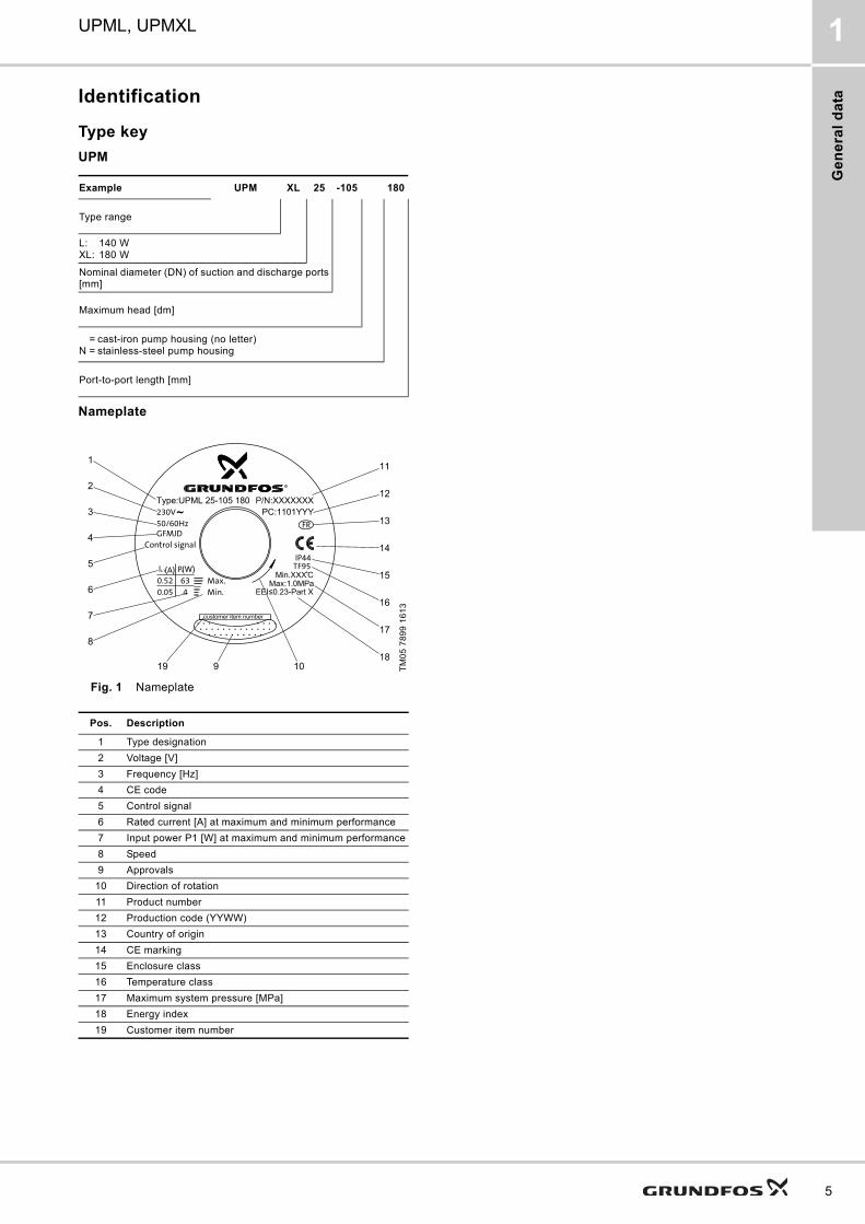
Identification
Type key
UPM
Nameplate
Fig. 1 Nameplate
Example UPM XL 25 -105 180
Type range
L: 140 WXL: 180 W
Nominal diameter (DN) of suction and discharge ports [mm]
Maximum head [dm]
= cast-iron pump housing (no letter)N = stainless-steel pump housing
Port-to-port length [mm]
TM
05
78
99
16
13
Pos. Description
1 Type designation
2 Voltage [V]
3 Frequency [Hz]
4 CE code
5 Control signal
6 Rated current [A] at maximum and minimum performance
7 Input power P1 [W] at maximum and minimum performance
8 Speed
9 Approvals
10 Direction of rotation
11 Product number
12 Production code (YYWW)
13 Country of origin
14 CE marking
15 Enclosure class
16 Temperature class
17 Maximum system pressure [MPa]
18 Energy index
19 Customer item number
5

Ge
ne
ral d
ata
6
UPML, UPMXL1
Performance range
TM
05
72
20
07
12
TM
05
72
28
07
12
0.0 0.5 1.0 1.5 2.0 2.5 3.0 3.5 4.0 4.5 5.0 5.5 6.0 Q [m³/h]0
2
4
6
8
10
12
14
H[m]
0.0 0.2 0.4 0.6 0.8 1.0 1.2 1.4 1.6 Q [l/s]
SOLARPML XX 145
UPML XX 105
UPMXL XX 125
0.0 0.5 1.0 1.5 2.0 2.5 3.0 3.5 4.0 4.5 5.0 5.5 6.0 Q [m³/h]0
2
4
6
8
10
12
H[m]
0.0 0.2 0.4 0.6 0.8 1.0 1.2 1.4 1.6 Q [l/s]
UPML XX-95 AUTO
UPMXL XX 105 AUTO

Pro
du
ct
ran
ge
UPML, UPMXL 2
2. Product range
UPML, UPMXL
1 x 230-240 V, 50/60 Hz
Pump typePort-to-port length
[mm]Connection pipe
threadControl signal
Data sheetpage
UPML 25-95 130 AUTO 130 mm R1 / G1 1/2
AUTO
22
UPML 25-95 180 AUTO
180 mm
R1 / G1 1/2 23
UPML 25-95 180 N AUTO R1 / G1 1/2 24
UPML 32-95 180 AUTO R1 1/2 / G2 25
UPML 25-105 130 PWM 130 mm R1 / G1 1/2
PWM
26
UPML 25-105 180 PWM
180 mm
R1 / G1 1/2 27
UPML 32-105 180 PWM R1 1/2 / G2 28
UPML 25-105 180 N PWM R1 / G1 1/2 29
UPMXL 25-105 130 AUTO 130 mm R1 / G1 1/2
AUTO
30
UPMXL 25-105 180 AUTO
180 mm
R1 / G1 1/2 31
UPMXL 25-105 180 N AUTO R1 / G1 1/2 32
UPMXL 32-105 180 AUTO R1 1/2 / G2 33
UPML GEO 25-105 130 PWM 130 mm R1 / G1 1/2
PWM
34
UPML GEO 25-105 180 PWM
180 mm
R1 / G1 1/2 35
UPML GEO 25-105 180 N PWM R1 / G1 1/2 36
UPML GEO 32-105 180 PWM R1 1/2 / G2 37
UPMXL GEO 25-125 130 PWM 130 mm R1 / G1 1/2
PWM
38
UPMXL GEO 25-125 180 PWM
180 mm
R1 / G1 1/2 39
UPMXL GEO 25-125 180 N PWM R1 / G1 1/2 40
UPMXL GEO 32-125 180 PWM R1 1/2 / G2 41
SOLAR PML 25-145 130 PWM 130 mm R1 / G1 1/2
PWM
42
SOLAR PML 25-145 180 PWM
180 mm
R1 / G1 1/2 43
SOLAR PML 25-145 180 N PWM R1 / G1 1/2 44
SOLAR PML 32-145 180 PWM R1 1/2 / G2 45
7

Co
ntro
l mo
de
an
d s
ign
als
8
UPML, UPMXL3
3. Control mode and signals
The UPML, UPMXL and SOLAR pumps are controlled via a digital low-voltage pulse-width modulation (PWM) signal which means that the speed of rotation depends on the input signal. The speed changes as a function of the input profile.
Digital low voltage PWM signal
SignalThe PWM signal is a square wave pulse width modulated signal designed to the frequency range 100-4000 Hz.
The PWM signal is used to select the speed (speed command) and as feedback signal.
The PWM frequency of the feedback signal is fixed at 75 Hz in the pump.
Duty cycle
d % 100 x t/T
Example
T = 2 ms
t = 0.6 ms
d %= 100 x 0.6 / 2 = 30 %
Rating
UIH 4-24 V
UIL < 1 V
IIH < 10 mA
Fig. 2 Low-voltage PWM signal
The signal is used to select speed (speed command) and as load feedback. The PWM frequency of the feedback signal is fixed in the pump to 75 Hz.
The interface
Fig. 3 Schematic drawing, interface
36 V Zener and R = 470 Ω
The UPML, UPMXL interface consists of an electronic part connecting the external control signal to the pump. The interface translates the external signal into a signal type that the microprocessor can understand. In addition, the interface ensures that the user cannot get into contact with dangerous voltage if touching the signal wires when 230 V is connected to the pump.
TM
04
99
11 0
211
Abbreviation Description
T Period of time [sec.]
d Duty cycle (t/T)
UiH High-level input voltage
UiL Low-level input voltage
IiH High-level input current
_(ordered China)
T
t
UiH
UiL
TM
04
99
12
03
11
Note"Signal ref." is a signal reference with no connection to protective earth.
8 mm galvanic isolation
PWM output
PWM input
Signal ref.
Pu
mp
ele
ctro
nic
s
R
Z

Co
ntr
ol
mo
de
an
d s
ign
als
UPML, UPMXL 3
PWM input signal profile HEATING
Input signal profile HEATING for heating and geothermal applications
At high PWM signal percentages (duty cycles), a hysteresis prevents the pump from starting and stopping if the input signal fluctuates around the shifting point. At low PWM signal percentages, the pump speed is high for safety reasons. In case of a cable breakage in a gas boiler system, the pumps will continue to run at maximum speed to transfer heat from the primary heat exchanger. This is also suitable for heating pumps to ensure that the pumps transfer heat in case of a cable breakage.
Fig. 4 PWM input profile HEATING
PWM input signal profile SOLAR
Input signal profile SOLAR for solar thermal applications
At low PWM signal [%] (duty cycles), a hysteresis prevents the pump from starting and stopping if the input signal fluctuates around the shifting point. Without PWM signal, the pump will stop for safety reasons. If a signal is missing, for example due to cable breakage, the pump will stop to avoid overheating of the solar thermal system.
Fig. 5 PWM input profile SOLAR
TM
04
99
85
03
11
Max.
Min.
PWM input signal [%]
Sp
ee
d
Stop
PWM input signal [%] Pump status
≤ 10 Maximum speed: Max.
> 10 / ≤ 84 Variable speed: Min. to max.
> 84 / ≤ 91 Minimum speed: Min.
> 91 / ≤ 95 Hysteresis area: On/off
> 95 / ≤ 100 Standby mode: Off
TM
05
15
75
32
11
Sp
ee
d
PWM input signal [%]
Max.
Min.
Off
9

Co
ntro
l mo
de
an
d s
ign
als
10
UPML, UPMXL3
PWM feedback signalA PWM feedback signal provides information about the current performance of the pump, such as current power consumption or various alarm or warning modes. See figures 5 or 6.
Alarms
Alarm output signals are available. Some PWM output signals are dedicated to alarm information. If the supply voltage is measured to a value below 195 V, the output signal is set to 75 %. If, at the same time, the rotor is locked due to deposits in the hydraulics, the output signal is set to 90 %, as this alarm is given a higher priority.
Fig. 6 PWM feedback signal
PWM input signal [%] Pump status
≤ 5 Standby mode: Off
> 5 / ≤ 8 Hysteresis area: On/off
> 8 / ≤ 15 Minimum speed: Min. (pump is running at minimum speed)
> 15 / ≤ 90 Variable speed: Min. to max.
> 90 / ≤ 100 Maximum speed: Max.
TM
05
75
18
12
13
25 50 100 150 200 250
10
20
30
40
50
60
70
80
90
100
1
2
Standby (stop)
Alarm stop: Fault, blocked pump
Alarm stop: Electrical fault
Warning
PW
M o
utp
ut
[%]
Ou
tpu
t fr
eq
ue
ncy
: 7
5 H
z ±
5 %
Power [W]
Slope: 3 W
/%
Slope
: 2 W
/%
Pos. Description
1 UPML saturation point, 140 W.
2 UPMXL saturation point, 210 W
PWM ouput signal [%] Indicates Pump operation
95 Standby Stop
90 Rotor blocked Stop
85 Undervoltage stop Stop
75 Undervoltage warning at Un -15 % Pump performance is reduced from Un -10 %.
0-70 Power [W] Pump is running according to setpoint.

Co
ntr
ol
mo
de
an
d s
ign
als
UPML, UPMXL 3
PWM feedback signal - flow estimation
Alarms
Alarm output signals are available. Some PWM output signals are dedicated to alarm information. If the supply voltage is measured to a value below 195 V, the output signal is set to 75 %. If, at the same time, the rotor is locked due to deposits in the hydraulics, the output signal is set to 90 %, as this alarm is given a higher priority.
Flow estimation
The PWM feedback signal can be used to measure the flow of the pump.
Fig. 7 PWM feedback signal
Data
TM
06
09
33
12
14
10
20
30
40
50
60
70
80
90
100
0 1.0 2.0 3.0 3.5 4.0Flow [m3/h]
STANDBY (Stop)
ALARM Stop: BLOCKED ERROR
ALARM Stop: ELECTRICAL ERROR
WARNING: ELECTRONIC HIGH TEMP
WARNINGSaturation at 4 [m3/h]
PW
M o
utp
ut
[%]
Ou
tpu
t fr
eq
.:7
5 H
z +
/- 5
%]
0.0 - 4 [m
3 /h] (Slope 0.057m [m
3 /h]
Maximum rating Symbol Value
PWM frequency input
High-speed optocoupler f 100-4000 Hz
Guaranteed standby power consumption < 3 W
Rated input voltage
High level UiH 4-24 V
Low level UiL < 1V
High-level input current IiH < 10 mA
Input duty cycle PWM 0-100 %
PWM frequency output, open collector f 75 Hz ± 5 %
Accuracy of output signal regarding power consumption - ± 2 % of PWM signal
Note: A PWM output signal below 5 % is too inaccurate for the calculation of the flow.Accuracy of output signal regarding flow:
< 1 m3/h ± 0.1 m3/h> 1 m3/h ± 0.2 m3/h
Output duty cycle PWM 0-100 %
Collector emitter breakdown voltage on output transistor Uc < 70 V
Collector current on output transistor Ic < 50 mA
Maximum power dissipation on output resistor PR 60 mW
Zener diode working voltage Uz 36 V
Maximum power dissipation in Zener diode Pz 500 mW
11

Co
ntro
l mo
de
an
d s
ign
als
12
UPML, UPMXL3
User interface
AUTO versionsThe UPML AUTO, UPMXL AUTO pumps are internally controlled. Via user interface it is possible to select two control modes with three curves each:
Proportional pressure
Proportional pressure mode offers the best energy savings. The maximum head (differential pressure) of the pump curve will be reached at the maximum performance curve of the pump. The speed will be automatically reduced at reduced flow to minimum 50 % of the maximum head at zero flow.
Constant pressure/power
Constant pressure/power mode limits the maximum power consumption like the performance of standard pumps with speed selector. At reduced flow, the head will increase. When the maximum head selected is reached, the speed of the pump will be reduced to keep this head (differential pressure) down to zero flow.
ApplicationsProportional pressure mode should be chosen in systems with variable flow, where the resistance of the heat consumers, such as radiators, is relatively low to the total friction loss of the system (< 50 %) as it is typically in 2-pipe heating systems with radiators and thermostatic valves.
Constant pressure mode should be chosen in systems with variable flow, where the resistance of the heat consumers is relatively high to the total friction loss of the system (> 50 %). This is typical in floor heating systems with thermostatic valves or in systems with constant flow. If the boilers have no control signal available, this is the preferred control mode.

Co
ns
tru
cti
on
UPML, UPMXL 4
4. Construction
Exploded view
Fig. 8 UPML, UPMXL and SOLAR
TM
05
04
18
111
3
UPMXL
13
Co
ns
truc
tion
14
UPML, UPMXL4
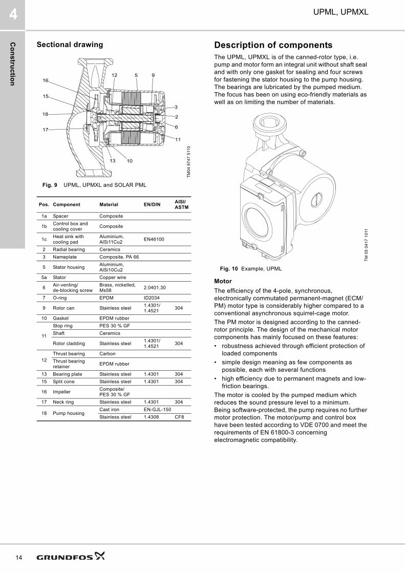
Sectional drawing
Fig. 9 UPML, UPMXL and SOLAR PML
Description of componentsThe UPML, UPMXL is of the canned-rotor type, i.e. pump and motor form an integral unit without shaft seal and with only one gasket for sealing and four screws for fastening the stator housing to the pump housing. The bearings are lubricated by the pumped medium. The focus has been on using eco-friendly materials as well as on limiting the number of materials.
Fig. 10 Example, UPML
Motor
The efficiency of the 4-pole, synchronous, electronically commutated permanent-magnet (ECM/PM) motor type is considerably higher compared to a conventional asynchronous squirrel-cage motor.
The PM motor is designed according to the canned-rotor principle. The design of the mechanical motor components has mainly focused on these features:
• robustness achieved through efficient protection of loaded components
• simple design meaning as few components as possible, each with several functions
• high efficiency due to permanent magnets and low-friction bearings.
The motor is cooled by the pumped medium which reduces the sound pressure level to a minimum. Being software-protected, the pump requires no further motor protection. The motor/pump and control box have been tested according to VDE 0700 and meet the requirements of EN 61800-3 concerning electromagnetic compatibility.
TM
04
97
47
511
0
Pos. Component Material EN/DINAISI/ASTM
1a Spacer Composite
1bControl box and cooling cover
Composite
1cHeat sink with cooling pad
Aluminium, AlSi11Cu2
EN46100
2 Radial bearing Ceramics
3 Nameplate Composite, PA 66
5 Stator housingAluminium, AlSi10Cu2
5a Stator Copper wire
6Air-venting/de-blocking screw
Brass, nickelled, Ms58
2.0401.30
7 O-ring EPDM ID2034
9 Rotor can Stainless steel1.4301/1.4521
304
10 Gasket EPDM rubber
11
Stop ring PES 30 % GF
Shaft Ceramics
Rotor cladding Stainless steel1.4301/1.4521
304
12Thrust bearing Carbon
Thrust bearing retainer
EPDM rubber
13 Bearing plate Stainless steel 1.4301 304
15 Split cone Stainless steel 1.4301 304
16 ImpellerComposite/PES 30 % GF
17 Neck ring Stainless steel 1.4301 304
18 Pump housingCast iron EN-GJL-150
Stainless steel 1.4308 CF8
TM
05
04
17
10
11

Co
ns
tru
cti
on
UPML, UPMXL 4
Stator housing
The die-cast stator housing with four fixing holes enables condensed water to escape from the pump through three drain holes, close to the pump housing. Consequently, one of the drain holes must always point downwards. See fig. 11.
The housings are electrocoated.
Fig. 11 Drain hole in stator housing
Stator and windings
The UPML, UPMXL pumps have a three-phase stator.
The UPML GEO, UPMXL GEO pumps are designed for pumping very cold liquids (down to -10 °C). In such applications, condensation may occur in the stator housing. To protect the stator, the copper wires are provided with reinforced insulation.
Fig. 12 Stator
Shaft with rotor
The shaft is made of ceramics. The rotor core is made of iron lamination and fitted with neodymium permanent magnets. The rotor is fitted to the shaft with a pipe and an elastic sleeve. The rotor is encapsulated in a thin stainless-steel cladding welded to the end covers and shaft pipe. To avoid precipitation of calcium in the radial bearings, the shaft has been plunge-ground at the journals. It has a through-going hole to ensure good lubrication and cooling of the upper bearing. Air in the rotor chamber escapes into the system through the through-going holes of the shaft.
Fig. 13 Shaft with rotor
Stop ring
The stop ring protects the rotor against axial translation towards the radial bearing at the top of the rotor can. The stop ring is made of PES.
Fig. 14 Stop ring
Rotor can
The drawn stainless-steel rotor holds the ground and honed upper radial bearing at the top. The rotor can has an air-venting/de-blocking screw.
Fig. 15 Rotor can
TM
05
04
13
10
11T
M0
5 0
41
5 1
011
TM
06
09
34
12
14
TM
05
79
95
17
13
TM
05
04
16
10
11
15

Co
ns
truc
tion
16
UPML, UPMXL4
Bearing plate
The bearing plate is made of stainless steel. The ground and honed inner radial bearing is pressed into the bearing plate. Thanks to the relatively large bearing plate surface, the motor heat is effectively carried away by the pumped medium. The four tiny laser holes of the bearing plate ensure optimum venting and minimise the gradual replacement of rotor liquid with the pumped medium.
Fig. 16 Bearing plate
Thrust bearing
The thrust bearing is fitted to the shaft in a flexible suspension. In combination with the bearing plate, the thrust bearing prevents forces from being transmitted axially to rotor and rotor can.
Fig. 17 Thrust bearing
Impeller
The composite impeller is of the radial type with curved blades. See fig. 18. The impeller is secured to the shaft with a split cone. See fig. 8, pos. 15. The impeller, shaft with rotor and bearing plate are assembled in one unit to eliminate possible misalignment in the bearings.
Fig. 18 Impeller
Pump housing
As standard, the pump housing is available in electrocoated cast iron with threaded suction and discharge ports. The pump housing is of the in-line type. The stainless-steel neck ring is pressed into the pump housing to minimise the amount of liquid running from the discharge side of the impeller to the suction side.
Fig. 19 Pump housing
Control box
The control box is made of black composite material with an aluminium heat sink. It contains the PCBs for internal power supply and communication.
The spacer fitted between stator and control box decreases the temperature influence of the pumped medium/motor temperature. The XL versions have an additional extended heat sink. The height will be extended by approx. 21 mm.
Fig. 20 Control box for UPML
TM
06
09
35
12
14
TM
06
09
36
12
14
TM
06
09
37
12
14
TM
03
97
32
43
07
TM
05
04
12
10
11

Ins
tall
ati
on
UPML, UPMXL 5
5. Installation
Mechanical installationMounting dimensions appear from the data sheets. See pages 22 to 45. Arrows on the pump housing indicate the liquid flow direction through the pump. The pump is designed to be installed pumping upwards, downwards or horizontally.
Note: The pump must always be installed with horizontal motor shaft within ± 5 °.The pump should be installed in the system in such a way that no major amount of air flowing through the pump or gathering in the pump housing will affect the pump when it is out of operation. If, in addition, a non-return valve is installed in the flow pipe, there is a high risk of dry running as the air cannot pass the valve.
Control box positionsThe permissible control box positions are indicated in the specific pump data sheets. See pages 22 to 45.
Changing the control box positionTo change the control box position, remove the screws holding the pump head, and turn the control box to the desired position. Replace the screws and tighten securely. The drain holes in the stator housing must point downwards.
Fig. 21 Control box positions
InsulationWhen the pump is to be insulated, the control box (especially the cooling cover) must not be covered to allow cooling by the surrounding air. If the pump is installed in a cabinet or fitted with insulation shells, the inside air temperature has to be evaluated. If constant ambient air temperatures higher than 55 °C are to be expected, please contact the Grundfos HVAC OEM Division. Diffusion-tight, cold-water insulation must not cover the pump head. The drain holes located in the stator housing must always be free.
Inlet pressureTo avoid cavitation noise and damage to the pump bearings, these minimum pressures are required at the pump suction port.
Note
Before any dismantling of the pump, the system must be drained, or the isolating valves on either side of the pump must be closed.
TM
04
94
82
43
10
Liquid temperature
85 °C 90 °C 110 °C
Inlet pressure0.5 m head 2.8 m head 11.0 m head
0.049 bar 0.27 bar 1.08 bar
17

Ins
talla
tion
18
UPML, UPMXL5
Electrical connectionThe electrical connection and protection must be carried out in accordance with local regulations. The pump requires no external motor protection.
Check that the supply voltage and frequency correspond to the values stated on the nameplate.
Supply voltage1 x 230 V + 10 %/- 15 %, 50/60 Hz.
Reduced supply voltageThe pump will run with reduced performance at voltages down to 160 VAC.
Inrush currentThe inrush current is the charge current to the electrolytic capacitor in the power supply to the electronics. The maximum current amplitude depends on the power supply and the complete wiring from the distributor transformer to the pump.
The pump is internally controlled by a small frequency converter running on a DC voltage. Therefore, the 230 VAC supply voltage is rectified to a DC voltage before it reaches the frequency converter. This is done by a rectifier and a capacitor. See fig. 22.
Fig. 22 Rectification of VAC voltage to DC voltage
The load of electronically commutated motors (ECM) behaves as a capacitive load and not as a motor load like in a standard pump.
When the power supply is switched on, the capacitor will behave as a short-circuit (it is "empty", meaning it has not been charged). Therefore, the current is only limited by the sum of the resistance in the NTC thermistor and the resistance in the coil of the EMC filter. If the pump is switched on again, while the NTC is still hot, its influence is reduced significantly. At low medium/ambient temperature, the NTC is normally cooled down after some minutes, at higher temperature it might last much longer.
If the power supply is switched on when the supply voltage is at its highest level, the inrush current can become up to 10.3 A (see below) for a very short period of time. After this period of time, the current will drop to the rated current.
Note: The inrush current of 10.3 A is measured on a flicker network according to IEC 61000-3-3:1994 + A1, + A2, Annex B.
When the power supply to the pump is switched on and off via an external relay, it must be ensured that the contact material of the relay is able to handle higher inrush currents.
We recommend to use special inrush relays with silver tin oxide (AgSnO) contacts.
Leakage current The pump mains filter will cause a discharge current to earth when powered.
High-voltage testThe pump incorporates filter components that are connected to protective earth. Therefore, a standard high-voltage test cannot be made without damaging the filters.
Earth leakage circuit breaker (ELCB)If the pump is connected to an electric installation where an earth leakage circuit breaker (ELCB) is used as additional protection, this circuit breaker must trip when earth fault currents with DC content (pulsating DC) occur (type A).
The earth leakage circuit breaker must be marked with the symbol shown in fig. 23.
Fig. 23 Symbol on earth leakage circuit breaker
TM
05
11
57
23
11
EMC filter NTC thermistor Rectifier
Capacitor
DC voltage to the frequency converter
TM
A0
67
89
25
11

Ins
tall
ati
on
UPML, UPMXL 5
Blue pos. 3 (N)
Brown pos. 1 (L)
Yellow/Green pos.2 (earth)
Power supplyThe pump must not be used with an external speed control which varies the supply voltage, for example phase-cut or pulse-cascade control.
The pump can be connected to the power supply in different ways, depending on the pump model.
Note: All cables and connectors used must comply with EN 60335-1.
Signal cableThe UPML AUTO, UPMXL AUTO pumps are internally speed-controlled and have no signal cable connection.
The UPML, UPMXL PWM pumps are externally speed-controlled. To enable pump control, a signal cable is required, otherwise the pump will always run at maximum speed (profile HEATING for heating and GEO). The SOLAR PML will not run without signal (PWM profile SOLAR). The signal cable has three leads, i.e. signal input, signal output and signal ref. The cable must be connected to the control box by a Dubox housing with a FCI terminal block and terminals. The optional signal cable can be supplied with the pump as an accessory. The cable length is customised to specific requirements (maximum 3 metres).
Fig. 24 Signal cable
Start upDo not start the pump until the system has been filled with liquid and vented. Being self-venting, the rotor can does not require venting before start-up. Air inside the pump will be transported by the medium into the system during the first minutes after pump start-up.
Furthermore, the required minimum inlet pressure must be available at the pump inlet.
The system cannot be vented through the pump. As the pump is self-venting, it does not need to be vented before start-up. However, it is recommended to vent pumps installed in systems where the pumped medium is very dirty, as well as after service of the pump. The screw may be loosened to check if the system has been vented completely.
It may happen that the pump stops when the air-venting/de-blocking screw is loosened.
When connected to an external PWM signal, the pump speed is controlled by an external controller which may even stop the pump. Without signal, the pump will run at maximum performance (profile HEATING) or stop (profile SOLAR).
DisposalThis product or parts of it must be disposed of in an environmentally sound way:
1. Use the public or private waste collection service.
2. If this is not possible, contact the nearest Grundfos company or service workshop.
Plug connection Description
TM
05
84
12
23
13
Molex 3-pin plugFor UPML, UPML GEO and SOLAR PML is mounted on the control box (NTC integrated in PCB) and pointing towards or away from the nameplate. For UPMXL and UPMXL GEO pumps, the plug is mounted on a 195 mm cable with integrated NTC.
TM
05
04
19
10
11
Volex plug For UPML, UPML GEO and SOLAR PML, the plug is mounted on the control box (NTC integrated in PCB) and pointing towards or away from the nameplate.For UPMXL and UPMXL GEO pumps, the plug is mounted on a 170 mm cable with integrated NTC.
Superseal plugFor UPML, UPML GEO and SOLAR PML, the plug is mounted on the control box, pointing towards or away from the nameplate.For UPMXL and UPMXL GEO pumps, the plug is mounted on a cable with integrated NTC.
Neutral: N (blue)
Line/phase: L (brown)
Protective earth: (yellow/green)
Line/phase: L (brown)
Neutral: N (blue)
Protective earth: (yellow/green)
TM
05
11
09
211
1
CautionWhen loosening the air-venting/de-blocking screw, be aware of hot, spraying water.
Black: PWM output
Blue: Signal ref.
Brown: PWM inputPlug
19

Op
era
tion
20
UPML, UPMXL6
6. Operation
The user interface allows to select between 6 control curves in two control modes:
• three proportional pressure curves (PP)
• three constant pressure/power curves (CP).
Fig. 25 Serial curve setting
Factory presettingProportional pressure curve, PP2:
• Push the button for two seconds:
– Pump goes to setting mode - LED starts flashing.
• With each push, the setting changes:
– LED 1-2-3 are permanently on, and then the control curve and mode is changed.
• Flashing mode:
– Fast: Proportional pressure
– Slow: Constant pressure/power
• After ten seconds not pushing the button:
– Setting is adapted.
– Pump returns to operating mode
• LED 1 or 2 or 3 is permanently on.
– Pump is running with the selected curve and mode.
Fig. 26 LED indication of the curve setting
TM
05
75
64
12
13
PP1 PP2 PP3
CP1CP2CP3

Ac
ce
ss
ori
es
UPML, UPMXL 7
7. Accessories
Product Description Product number
Power supply plug with cable
TM
05
11
02
211
1
Volex power supply cable, 2000 mm, H03V2V2-F 3G 0.75 ZW 105 GR, 3 x 0.75 mm2, with wire pins and moulded cable relief
97940975
TM
05
11
03
211
1
Molex power supply cable, 2000 mm, H03V2V2-F 3G 0.75 ZW 105 GR, 3 x 0.75 mm2, with wire pins
97940977
Signal cable and blanking plug
TM
05
11
06
211
1
PWM signal cable, 2000 mm, RKK90 3 x 0.50 ZW 3 x 0.50 mm2 97940991
TM
05
11
07
211
1
Blanking plug for PWM signal plug-in 97823485
NTC counter cable
TM
06
09
42
12
14
MOLEX NTC counter cable 2m 3x0,75mm² 97923300
TM
06
09
43
12
14
VOLEX NTC Counter Cable 2m 3x0,75mm² 97923299
Pat
ent P
endi
ngP
aten
t Pen
ding
21

8UPML, UPMXL
Pe
rfo
rma
nc
e c
urv
es
an
d t
ec
hn
ica
l d
ata
8. Performance curves and technical data
UPML 25-95 130 AUTO, 1 x 230 V, 50/60 Hz
Electrical data, 1 x 230 V, 50 Hz
Dimensional sketches and control box positions
Technical data
TM
05
79
60
17
13
Speed P1 [W] I1/1 [A]
Min. 12 0.1
Max. 140 1.1
TM
05
74
27
33
12
EEI ≤ 0.23
0.0 0.5 1.0 1.5 2.0 2.5 3.0 3.5 4.0 4.5 5.0 Q [m³/h]
0
2
4
6
8
10
[m]H
0
20
40
60
80
100
[kPa]p
0.0 0.2 0.4 0.6 0.8 1.0 1.2 1.4 Q [l/s]
CP
PP
0.0 0.5 1.0 1.5 2.0 2.5 3.0 3.5 4.0 4.5 5.0 Q [m³/h]
0
20
40
60
80
100
120
140[W]P1
Pump typeDimensions [mm]
L1 L2 L3 B3 B4 B5 H1 H2 ConnectionNet weight
[kg]Quantity per
pallet
UPML 25-95 130 22 131 95 50 64 27 112 G 1 1/2 2.4 -
System pressure: Max. 1.0 MPa (10 bar) Enclosure class: IPX2D
Minimum inlet pressure: 0.01 MPa (0.10 bar) at 95 °C liquid temperature Insulation class: H
Liquid temperature: -10 °C to +95 °C (TF 95) Equipment class: I
Motor protection: Overload protection Approval and marking: VDE, CE
22

8UPML, UPMXL
UP
ML
25
-95
18
0 A
UT
O,
1 x
23
0 V
, 5
0/6
0 H
z
Performance curves and technical data
UPML 25-95 180 AUTO, 1 x 230 V, 50/60 Hz
Electrical data, 1 x 230 V, 50 Hz
Dimensional sketches and control box positions
Technical data
TM
05
79
60
17
13
Speed P1 [W] I1/1 [A]
Min. 12 0.1
Max. 140 1.1
TM
05
74
27
33
12
Pump typeDimensions [mm]
L1 L2 L3 B3 B4 B5 H1 H2 ConnectionNet weight
[kg]Quantity per
pallet
UPML 25-95 180 3.5 131 95 50 64 38 104 G 1 1/2 2.5 -
System pressure: Max. 1.0 MPa (10 bar) Enclosure class: IPX2D
Minimum inlet pressure: 0.01 MPa (0.10 bar) at 95 °C liquid temperature Insulation class: H
Liquid temperature: -10 °C to +95 °C (TF 95) Equipment class: I
Motor protection: Overload protection Approval and marking: VDE, CE
EEI ≤ 0.23
0.0 0.5 1.0 1.5 2.0 2.5 3.0 3.5 4.0 4.5 5.0 Q [m³/h]
0
2
4
6
8
10
[m]H
0
20
40
60
80
100
[kPa]p
0.0 0.2 0.4 0.6 0.8 1.0 1.2 1.4 Q [l/s]
CP
PP
0.0 0.5 1.0 1.5 2.0 2.5 3.0 3.5 4.0 4.5 5.0 Q [m³/h]
0
20
40
60
80
100
120
140[W]P1
23

24
8 UPML, UPMXL
UP
ML
25
-95
N 1
80
AU
TO
, 1 x
23
0 V
, 50
/60
Hz
Performance curves and technical data
UPML 25-95 N 180 AUTO, 1 x 230 V, 50/60 Hz
Electrical data, 1 x 230 V, 50 Hz
Dimensional sketches and control box positions
Technical data
TM
05
79
60
17
13
Speed P1 [W] I1/1 [A]
Min. 12 0.1
Max. 140 1.1
TM
05
74
27
33
12
Pump typeDimensions [mm]
L1 L2 L3 B3 B4 B5 H1 H2 ConnectionNet weight
[kg]Quantity per
pallet
UPML 25-95 180 3.5 131 95 50 64 38 104 G 1 1/2 2.5 -
System pressure: Max. 1.0 MPa (10 bar) Enclosure class: IPX2D
Minimum inlet pressure: 0.01 MPa (0.10 bar) at 95 °C liquid temperature Insulation class: H
Liquid temperature: -10 °C to +95 °C (TF 95) Equipment class: I
Motor protection: Overload protection Approval and marking: VDE, CE
EEI ≤ 0.23
0.0 0.5 1.0 1.5 2.0 2.5 3.0 3.5 4.0 4.5 5.0 Q [m³/h]
0
2
4
6
8
10
[m]H
0
20
40
60
80
100
[kPa]p
0.0 0.2 0.4 0.6 0.8 1.0 1.2 1.4 Q [l/s]
CP
PP
0.0 0.5 1.0 1.5 2.0 2.5 3.0 3.5 4.0 4.5 5.0 Q [m³/h]
0
20
40
60
80
100
120
140[W]P1

8UPML, UPMXL
UP
ML
32
-95
18
0 A
UT
O,
1 x
23
0 V
, 5
0/6
0 H
z
Performance curves and technical data
UPML 32-95 180 AUTO, 1 x 230 V, 50/60 Hz
Electrical data, 1 x 230 V, 50 Hz
Dimensional sketches and control box positions
Technical data
TM
05
79
60
17
13
Speed P1 [W] I1/1 [A]
Min. 12 0.1
Max. 140 1.1
TM
05
74
27
33
12
Pump typeDimensions [mm]
L1 L2 L3 B3 B4 B5 H1 H2 ConnectionNet weight
[kg]Quantity per
pallet
UPML 32-95 180 3.5 131 95 50 64 38 104 G 2 2.9 -
System pressure: Max. 1.0 MPa (10 bar) Enclosure class: IPX2D
Minimum inlet pressure: 0.01 MPa (0.10 bar) at 95 °C liquid temperature Insulation class: H
Liquid temperature: -10°C to +95 °C (TF 95) Equipment class: I
Motor protection: Overload protection Approval and marking: VDE, CE
EEI ≤ 0.23
0.0 0.5 1.0 1.5 2.0 2.5 3.0 3.5 4.0 4.5 5.0 Q [m³/h]
0
2
4
6
8
10
[m]H
0
20
40
60
80
100
[kPa]p
0.0 0.2 0.4 0.6 0.8 1.0 1.2 1.4 Q [l/s]
CP
PP
0.0 0.5 1.0 1.5 2.0 2.5 3.0 3.5 4.0 4.5 5.0 Q [m³/h]
0
20
40
60
80
100
120
140[W]P1
25

26
8 UPML, UPMXL
UP
ML
25
-10
5 1
30
PW
M, 1
x 2
30
V, 5
0/6
0 H
z
Performance curves and technical data
UPML 25-105 130 PWM, 1 x 230 V, 50/60 Hz
Electrical data, 1 x 230 V, 50 Hz
Dimensional sketches and control box positions
Technical data
TM
05
72
51
08
13
Speed P1 [W] I1/1 [A]
Min. 3 0.04
Max. 140 1.1
TM
05
51
23
33
12
Pump typeDimensions [mm]
L1 L2 L3 B3 B4 B5 H1 H2 ConnectionNet weight
[kg]Quantity per
pallet
UPML 25 - 105 130 22 131 95 50 64 27 112 G 1 1/2 2.4 -
System pressure: Max. 1.0 MPa (10 bar) Enclosure class: IPX2D
Minimum inlet pressure: 0.01 MPa (0.10 bar) at 95 °C liquid temperature Insulation class: H
Liquid temperature: -10 °C to +95 °C (TF 95) Equipment class: I
Motor protection: Overload protection Approval and marking: VDE, CE
EEI ≤ 0.23
0.0 0.5 1.0 1.5 2.0 2.5 3.0 3.5 4.0 4.5 5.0 Q [m³/h]
0
2
4
6
8
10
[m]H
0
20
40
60
80
100
[kPa]p
0.0 0.2 0.4 0.6 0.8 1.0 1.2 1.4 Q [l/s]
0.0 0.5 1.0 1.5 2.0 2.5 3.0 3.5 4.0 4.5 5.0 Q [m³/h]
0
20
40
60
80
100
120
140[W]P1

8UPML, UPMXL
UP
ML
25
-10
5 1
80
PW
M,
1 x
23
0 V
, 5
0/6
0 H
z
Performance curves and technical data
UPML 25-105 180 PWM, 1 x 230 V, 50/60 Hz
Electrical data, 1 x 230 V, 50 Hz
Dimensional sketches and control box positions
Technical data
TM
05
72
51
08
13
Speed P1 [W] I1/1 [A]
Min. 3 0.04
Max. 140 1.1
TM
05
51
23
33
12
Pump typeDimensions [mm]
L1 L2 L3 B3 B4 B5 H1 H2 ConnectionNet weight
[kg]Quantity per
pallet
UPML 25-105 180 3.5 131 95 50 64 38 104 G 1 1/2 2.5 -
System pressure: Max. 1.0 MPa (10 bar) Enclosure class: IPX2D
Minimum inlet pressure: 0.01 MPa (0.10 bar) at 95 °C liquid temperature Insulation class: H
Liquid temperature: -10 °C to +95 °C (TF 95) Equipment class: I
Motor protection: Overload protection Approval and marking: VDE, CE
EEI ≤ 0.23
0.0 0.5 1.0 1.5 2.0 2.5 3.0 3.5 4.0 4.5 5.0 Q [m³/h]
0
2
4
6
8
10
[m]H
0
20
40
60
80
100
[kPa]p
0.0 0.2 0.4 0.6 0.8 1.0 1.2 1.4 Q [l/s]
0.0 0.5 1.0 1.5 2.0 2.5 3.0 3.5 4.0 4.5 5.0 Q [m³/h]
0
20
40
60
80
100
120
140[W]P1
27

28
8 UPML, UPMXL
UP
ML
32
-10
5 1
80
PW
M, 1
x 2
30
V, 5
0/6
0 H
z
Performance curves and technical data
UPML 32-105 180 PWM, 1 x 230 V, 50/60 Hz
Electrical data, 1 x 230 V, 50 Hz
Dimensional sketches and control box positions
Technical data
TM
05
72
51
08
13
Speed P1 [W] I1/1 [A]
Min. 3 0.04
Max. 140 1.1
TM
05
51
23
33
12
Pump typeDimensions [mm]
L1 L2 L3 B3 B4 B5 H1 H2 ConnectionNet weight
[kg]Quantity per
pallet
UPML 25-105 180 3.5 131 95 50 64 38 104 G 2 2.7 -
System pressure: Max. 1.0 MPa (10 bar) Enclosure class: IPX2D
Minimum inlet pressure: 0.01 MPa (0.10 bar) at 95 °C liquid temperature Insulation class: H
Liquid temperature: -10 °C to +95 °C (TF 95) Equipment class: I
Motor protection: Overload protection Approval and marking: VDE, CE
EEI ≤ 0.23
0.0 0.5 1.0 1.5 2.0 2.5 3.0 3.5 4.0 4.5 5.0 Q [m³/h]
0
2
4
6
8
10
[m]H
0
20
40
60
80
100
[kPa]p
0.0 0.2 0.4 0.6 0.8 1.0 1.2 1.4 Q [l/s]
0.0 0.5 1.0 1.5 2.0 2.5 3.0 3.5 4.0 4.5 5.0 Q [m³/h]
0
20
40
60
80
100
120
140[W]P1

8UPML, UPMXL
UP
ML
25
-10
5 1
80
N P
WM
, 1
x 2
30
V,
50
/60
Hz
Performance curves and technical data
UPML 25-105 180 N PWM, 1 x 230 V, 50/60 Hz
Electrical data, 1 x 230 V, 50 Hz
Dimensional sketches and control box positions
Technical data
TM
05
72
51
08
13
Speed P1 [W] I1/1 [A]
Min. 3 0.04
Max. 140 1.1
TM
05
51
23
33
12
Pump typeDimensions [mm]
L1 L2 L3 B3 B4 B5 H1 H2 ConnectionNet weight
[kg]Quantity per
pallet
UPML 25-105 180 3.5 131 95 50 64 38 104 G 1 1/2 2.6 -
System pressure: Max. 1.0 MPa (10 bar) Enclosure class: IPX2D
Minimum inlet pressure: 0.01 MPa (0.10 bar) at 95 °C liquid temperature Insulation class: H
Liquid temperature: -10 °C to +95 °C (TF 95) Equipment class: I
Motor protection: Overload protection Approval and marking: VDE, CE
EEI ≤ 0.23
0.0 0.5 1.0 1.5 2.0 2.5 3.0 3.5 4.0 4.5 5.0 Q [m³/h]
0
2
4
6
8
10
[m]H
0
20
40
60
80
100
[kPa]p
0.0 0.2 0.4 0.6 0.8 1.0 1.2 1.4 Q [l/s]
0.0 0.5 1.0 1.5 2.0 2.5 3.0 3.5 4.0 4.5 5.0 Q [m³/h]
0
20
40
60
80
100
120
140[W]P1
29

30
8 UPML, UPMXL
UP
MX
L 2
5-1
05
13
0 A
UT
O, 1
x 2
30
V, 5
0/6
0 H
z
Performance curves and technical data
UPMXL 25-105 130 AUTO, 1 x 230 V, 50/60 Hz
Electrical data, 1 x 230 V, 50 Hz
Dimensional sketches and control box positions
Technical data
TM
05
79
61
17
13
Speed P1 [W] I1/1 [A]
Min. 15 0.14
Max. 180 1.4
TM
05
55
98
33
12
Pump typeDimensions [mm]
L1 L2 L3 B3 B4 B5 H1 H2 ConnectionNet weight
[kg]Quantity per
pallet
UPMXL 25-105 130 22 131 117 50 64 27 112 G 1 1/2 2.6 -
System pressure: Max. 1.0 MPa (10 bar) Enclosure class: IPX2D
Minimum inlet pressure: 0.01 MPa (0.10 bar) at 95 °C liquid temperature Insulation class: H
Liquid temperature: -10 °C to +95 °C (TF 95) Equipment class: I
Motor protection: Overload protection Approval and marking: VDE, CE
EEI ≤ 0.23
0.0 0.5 1.0 1.5 2.0 2.5 3.0 3.5 4.0 4.5 5.0 5.5 6.0 Q [m³/h]
0
2
4
6
8
10
12
[m]H
0
20
40
60
80
100
120[kPa]
p
0.0 0.2 0.4 0.6 0.8 1.0 1.2 1.4 1.6 Q [l/s]
CP
PP
0.0 0.5 1.0 1.5 2.0 2.5 3.0 3.5 4.0 4.5 5.0 5.5 6.0 Q [m³/h]
0
40
80
120
160
200
[W]P1
Type XXXX XX-XX XXXXXXV ~XX/XXHzGFXXX
EuP ReadyI1/1(A) P1(W)X.XXX.XX
XXXX
Max.
Min.
P/N:XXXXXXXPC:XXXXXX
IP XXTF XX
Max.X.XMPa
A High Efficiency
XX
EEI<0.23

8UPML, UPMXL
UP
MX
L 2
5-1
05
18
0 A
UT
O,
1 x
23
0 V
, 5
0/6
0 H
z
Performance curves and technical data
UPMXL 25-105 180 AUTO, 1 x 230 V, 50/60 Hz
Electrical data, 1 x 230 V, 50 Hz
Dimensional sketches and control box positions
Technical data
TM
05
79
61
17
13
Speed P1 [W] I1/1 [A]
Min. 15 0.14
Max. 180 1.4
TM
05
55
98
33
12
Pump typeDimensions [mm]
L1 L2 L3 B3 B4 B5 H1 H2 ConnectionNet weight
[kg]Quantity per
pallet
UPMXL 25-105 180 3.5 131 117 50 64 38 104 G 1 1/2 2.7 -
System pressure: Max. 1.0 MPa (10 bar) Enclosure class: IPX2D
Minimum inlet pressure: 0.01 MPa (0.10 bar) at 95 °C liquid temperature Insulation class: H
Liquid temperature: -10 °C to +95 °C (TF 95) Equipment class: I
Motor protection: Overload protection Approval and marking: VDE, CE
EEI ≤ 0.23
0.0 0.5 1.0 1.5 2.0 2.5 3.0 3.5 4.0 4.5 5.0 5.5 6.0 Q [m³/h]
0
2
4
6
8
10
12
[m]H
0
20
40
60
80
100
120[kPa]
p
0.0 0.2 0.4 0.6 0.8 1.0 1.2 1.4 1.6 Q [l/s]
CP
PP
0.0 0.5 1.0 1.5 2.0 2.5 3.0 3.5 4.0 4.5 5.0 5.5 6.0 Q [m³/h]
0
40
80
120
160
200
[W]P1
Type XXXX XX-XX XXXXXXV ~XX/XXHzGFXXX
EuP ReadyI1/1(A) P1(W)X.XXX.XX
XXXX
Max.
Min.
P/N:XXXXXXXPC:XXXXXX
IP XXTF XX
Max.X.XMPa
A High Efficiency
XX
EEI<0.23
31
32
8 UPML, UPMXL
UP
MX
L 2
5-1
05
18
0 N
AU
TO
, 1 x
23
0 V
, 50
/60
Hz
Performance curves and technical data
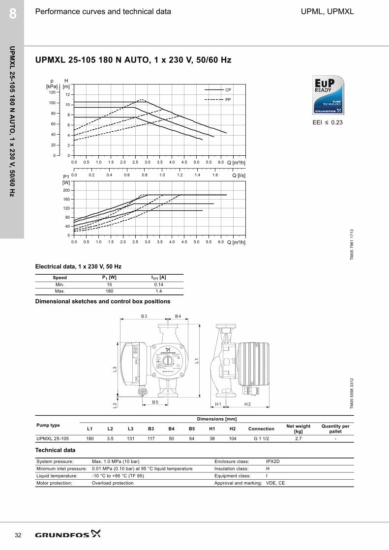
UPMXL 25-105 180 N AUTO, 1 x 230 V, 50/60 Hz
Electrical data, 1 x 230 V, 50 Hz
Dimensional sketches and control box positions
Technical data
TM
05
79
61
17
13
Speed P1 [W] I1/1 [A]
Min. 15 0.14
Max. 180 1.4
TM
05
55
98
33
12
Pump typeDimensions [mm]
L1 L2 L3 B3 B4 B5 H1 H2 ConnectionNet weight
[kg]Quantity per
pallet
UPMXL 25-105 180 3.5 131 117 50 64 38 104 G 1 1/2 2.7 -
System pressure: Max. 1.0 MPa (10 bar) Enclosure class: IPX2D
Minimum inlet pressure: 0.01 MPa (0.10 bar) at 95 °C liquid temperature Insulation class: H
Liquid temperature: -10 °C to +95 °C (TF 95) Equipment class: I
Motor protection: Overload protection Approval and marking: VDE, CE
EEI ≤ 0.23
0.0 0.5 1.0 1.5 2.0 2.5 3.0 3.5 4.0 4.5 5.0 5.5 6.0 Q [m³/h]
0
2
4
6
8
10
12
[m]H
0
20
40
60
80
100
120[kPa]
p
0.0 0.2 0.4 0.6 0.8 1.0 1.2 1.4 1.6 Q [l/s]
CP
PP
0.0 0.5 1.0 1.5 2.0 2.5 3.0 3.5 4.0 4.5 5.0 5.5 6.0 Q [m³/h]
0
40
80
120
160
200
[W]P1
Type XXXX XX-XX XXXXXXV ~XX/XXHzGFXXX
EuP ReadyI1/1(A) P1(W)X.XXX.XX
XXXX
Max.
Min.
P/N:XXXXXXXPC:XXXXXX
IP XXTF XX
Max.X.XMPa
A High Efficiency
XX
EEI<0.23

8UPML, UPMXL
UP
MX
L 3
2-1
05
18
0 A
UT
O,
1 x
23
0 V
, 5
0/6
0 H
z
Performance curves and technical data
UPMXL 32-105 180 AUTO, 1 x 230 V, 50/60 Hz
Electrical data, 1 x 230 V, 50 Hz
Dimensional sketches and control box positions
Technical data
TM
05
79
61
17
13
Speed P1 [W] I1/1 [A]
Min. 15 0.14
Max. 180 1.4
TM
05
55
98
33
12
Pump typeDimensions [mm]
L1 L2 L3 B3 B4 B5 H1 H2 ConnectionNet weight
[kg]Quantity per
pallet
UPMXL 32-105 180 3.5 131 117 50 64 38 104 G 2 2.9 -
System pressure: Max. 1.0 MPa (10 bar) Enclosure class: IPX2D
Minimum inlet pressure: 0.01 MPa (0.10 bar) at 95 °C liquid temperature Insulation class: H
Liquid temperature: -10 °C to +95 °C (TF 95) Equipment class: I
Motor protection: Overload protection Approval and marking: VDE, CE
EEI ≤ 0.23
0.0 0.5 1.0 1.5 2.0 2.5 3.0 3.5 4.0 4.5 5.0 5.5 6.0 Q [m³/h]
0
2
4
6
8
10
12
[m]H
0
20
40
60
80
100
120[kPa]
p
0.0 0.2 0.4 0.6 0.8 1.0 1.2 1.4 1.6 Q [l/s]
CP
PP
0.0 0.5 1.0 1.5 2.0 2.5 3.0 3.5 4.0 4.5 5.0 5.5 6.0 Q [m³/h]
0
40
80
120
160
200
[W]P1
Type XXXX XX-XX XXXXXXV ~XX/XXHzGFXXX
EuP ReadyI1/1(A) P1(W)X.XXX.XX
XXXX
Max.
Min.
P/N:XXXXXXXPC:XXXXXX
IP XXTF XX
Max.X.XMPa
A High Efficiency
XX
EEI<0.23
33

34
8 UPML, UPMXL
UP
ML
GE
O 2
5-1
05
13
0 P
WM
, 1 x
23
0 V
, 50
/60
Hz
Performance curves and technical data
UPML GEO 25-105 130 PWM, 1 x 230 V, 50/60 Hz
Electrical data, 1 x 230 V, 50 Hz
Dimensional sketches and control box positions
Technical data
TM
05
72
51
08
13
Speed P1 [W] I1/1 [A]
Min. 3 0.04
Max. 140 1.1
TM
05
51
23
33
12
Pump typeDimensions [mm]
L1 L2 L3 B3 B4 B5 H1 H2 ConnectionNet weight
[kg]Quantity per
pallet
UPML GEO 25-105 130 22 131 95 50 64 27 112 G 1 1/2 2.4 -
System pressure: Max. 1.0 MPa (10 bar) Enclosure class: IPX2D
Minimum inlet pressure: 0.01 MPa (0.10 bar) at 95 °C liquid temperature Insulation class: H
Liquid temperature: -10 °C to +95 °C (TF 95) Equipment class: I
Motor protection: Overload protection Approval and marking: VDE, CE
EEI ≤ 0.23
0.0 0.5 1.0 1.5 2.0 2.5 3.0 3.5 4.0 4.5 5.0 Q [m³/h]
0
2
4
6
8
10
[m]H
0
20
40
60
80
100
[kPa]p
0.0 0.2 0.4 0.6 0.8 1.0 1.2 1.4 Q [l/s]
0.0 0.5 1.0 1.5 2.0 2.5 3.0 3.5 4.0 4.5 5.0 Q [m³/h]
0
20
40
60
80
100
120
140[W]P1

8UPML, UPMXL
UP
ML
GE
O 2
5-1
05
18
0,
PW
M,
1 x
23
0 V
, 5
0/6
0 H
z
Performance curves and technical data
UPML GEO 25-105 180, PWM, 1 x 230 V, 50/60 Hz
Electrical data, 1 x 230 V, 50 Hz
Dimensional sketches and control box positions
Technical data
TM
05
72
51
08
13
Speed P1 [W] I1/1 [A]
Min. 3 0.04
Max. 140 1.1
TM
05
51
23
33
12
Pump typeDimensions [mm]
L1 L2 L3 B3 B4 B5 H1 H2 ConnectionNet weight
[kg]Quantity per
pallet
UPML GEO 25-105 180 3.5 131 95 50 64 38 104 G 1 1/2 2.5 -
System pressure: Max. 1.0 MPa (10 bar) Enclosure class: IPX2D
Minimum inlet pressure: 0.01 MPa (0.10 bar) at 95 °C liquid temperature Insulation class: H
Liquid temperature: -10 °C to +95 °C (TF 95) Equipment class: I
Motor protection: Overload protection Approval and marking: VDE, CE
EEI ≤ 0.23
0.0 0.5 1.0 1.5 2.0 2.5 3.0 3.5 4.0 4.5 5.0 Q [m³/h]
0
2
4
6
8
10
[m]H
0
20
40
60
80
100
[kPa]p
0.0 0.2 0.4 0.6 0.8 1.0 1.2 1.4 Q [l/s]
0.0 0.5 1.0 1.5 2.0 2.5 3.0 3.5 4.0 4.5 5.0 Q [m³/h]
0
20
40
60
80
100
120
140[W]P1
35

36
8 UPML, UPMXL
UP
ML
GE
O 2
5-1
05
18
0 N
PW
M, 1
x 2
30
V, 5
0/6
0 H
z
Performance curves and technical data
UPML GEO 25-105 180 N PWM, 1 x 230 V, 50/60 Hz
Electrical data, 1 x 230 V, 50 Hz
Dimensional sketches and control box positions
Technical data
TM
05
72
51
08
13
Speed P1 [W] I1/1 [A]
Min. 3 0.04
Max. 140 1.1
TM
05
51
23
33
12
Pump typeDimensions [mm]
L1 L2 L3 B3 B4 B5 H1 H2 ConnectionNet weight
[kg]Quantity per
pallet
UPML GEO 25-105 180 3.5 131 95 50 64 38 104 G 1 1/2 2.5 -
System pressure: Max. 1.0 MPa (10 bar) Enclosure class: IPX2D
Minimum inlet pressure: 0.01 MPa (0.10 bar) at 95 °C liquid temperature Insulation class: H
Liquid temperature: -10 °C to +95 °C (TF 95) Equipment class: I
Motor protection: Overload protection Approval and marking: VDE, CE
EEI ≤ 0.23
0.0 0.5 1.0 1.5 2.0 2.5 3.0 3.5 4.0 4.5 5.0 Q [m³/h]
0
2
4
6
8
10
[m]H
0
20
40
60
80
100
[kPa]p
0.0 0.2 0.4 0.6 0.8 1.0 1.2 1.4 Q [l/s]
0.0 0.5 1.0 1.5 2.0 2.5 3.0 3.5 4.0 4.5 5.0 Q [m³/h]
0
20
40
60
80
100
120
140[W]P1

8UPML, UPMXL
UP
ML
GE
O 3
2-1
05
18
0 P
WM
, 1
x 2
30
V,
50
/60
Hz
Performance curves and technical data
UPML GEO 32-105 180 PWM, 1 x 230 V, 50/60 Hz
Electrical data, 1 x 230 V, 50 Hz
Dimensional sketches and control box positions
Technical data
TM
05
72
51
08
13
Speed P1 [W] I1/1 [A]
Min. 3 0.04
Max. 140 1.1
TM
05
51
23
33
12
Pump typeDimensions [mm]
L1 L2 L3 B3 B4 B5 H1 H2 ConnectionNet weight
[kg]Quantity per
pallet
UPML GEO 32-105 180 3.5 131 95 50 64 38 104 G 2 2.7 -
System pressure: Max. 1.0 MPa (10 bar) Enclosure class: IPX2D
Minimum inlet pressure: 0.01 MPa (0.10 bar) at 95 °C liquid temperature Insulation class: H
Liquid temperature: -10 °C to +95 °C (TF 95) Equipment class: I
Motor protection: Overload protection Approval and marking: VDE, CE
EEI ≤ 0.23
0.0 0.5 1.0 1.5 2.0 2.5 3.0 3.5 4.0 4.5 5.0 Q [m³/h]
0
2
4
6
8
10
[m]H
0
20
40
60
80
100
[kPa]p
0.0 0.2 0.4 0.6 0.8 1.0 1.2 1.4 Q [l/s]
0.0 0.5 1.0 1.5 2.0 2.5 3.0 3.5 4.0 4.5 5.0 Q [m³/h]
0
20
40
60
80
100
120
140[W]P1
37

38
8 UPML, UPMXL
UP
MX
L G
EO
25
-12
5 1
30
PW
M, 1
x 2
30
V, 5
0/6
0 H
z
Performance curves and technical data
UPMXL GEO 25-125 130 PWM, 1 x 230 V, 50/60 Hz
Electrical data, 1 x 230 V, 50 Hz
Dimensional sketches and control box positions
Technical data
TM
05
72
52
08
13
Speed P1 [W] I1/1 [A]
Min. 3 0.06
Max. 180 1.4
TM
05
74
28
33
12
Pump typeDimensions [mm]
L1 L2 L3 B3 B4 B5 H1 H2 ConnectionNet weight
[kg]Quantity per
pallet
UPMXL GEO 25-125 130 22 131 117 50 64 27 112 G 1 1/2 2.6 -
System pressure: Max. 1.0 MPa (10 bar) Enclosure class: IPX2D
Minimum inlet pressure: 0.01 MPa (0.10 bar) at 95 °C liquid temperature Insulation class: H
Liquid temperature: -10 °C to +95 °C (TF 95) Equipment class: I
Motor protection: Overload protection Approval and marking: VDE, CE
EEI ≤ 0.23
0.0 0.5 1.0 1.5 2.0 2.5 3.0 3.5 4.0 4.5 5.0 5.5 Q [m³/h]
0
2
4
6
8
10
12
[m]H
0
20
40
60
80
100
120[kPa]
p
0.0 0.2 0.4 0.6 0.8 1.0 1.2 1.4 1.6 Q [l/s]
0.0 0.5 1.0 1.5 2.0 2.5 3.0 3.5 4.0 4.5 5.0 5.5 Q [m³/h]
0
40
80
120
160
[W]P1
Type XXXX XX-XX XXXXXXV ~XX/XXHzGFXXX
EuP ReadyI1/1(A) P1(W)X.XXX.XX
XXXX
Max.
Min.
P/N:XXXXXXXPC:XXXXXX
IP XXTF XX
Max.X.XMPa
A High Efficiency
XX
EEI<0.23

8UPML, UPMXL
UP
MX
L G
EO
25
-12
5 1
80
PW
M,
1 x
23
0 V
, 5
0/6
0 H
z
Performance curves and technical data
UPMXL GEO 25-125 180 PWM, 1 x 230 V, 50/60 Hz
Electrical data, 1 x 230 V, 50 Hz
Dimensional sketches and control box positions
Technical data
TM
05
72
52
08
13
Speed P1 [W] I1/1 [A]
Min. 3 0.06
Max. 180 1.4
TM
05
74
28
33
12
Pump typeDimensions [mm]
L1 L2 L3 B3 B4 B5 H1 H2 ConnectionNet weight
[kg]Quantity per
pallet
UPMXL GEO 25-125 180 3.5 131 117 50 64 38 104 G 1 1/2 2.7 -
System pressure: Max. 1.0 MPa (10 bar) Enclosure class: IPX2D
Minimum inlet pressure: 0.01 MPa (0.10 bar) at 95 °C liquid temperature Insulation class: H
Liquid temperature: -10 °C to +95 °C (TF 95) Equipment class: I
Motor protection: Overload protection Approval and marking: VDE, CE
EEI ≤ 0.23
0.0 0.5 1.0 1.5 2.0 2.5 3.0 3.5 4.0 4.5 5.0 5.5 Q [m³/h]
0
2
4
6
8
10
12
[m]H
0
20
40
60
80
100
120[kPa]
p
0.0 0.2 0.4 0.6 0.8 1.0 1.2 1.4 1.6 Q [l/s]
0.0 0.5 1.0 1.5 2.0 2.5 3.0 3.5 4.0 4.5 5.0 5.5 Q [m³/h]
0
40
80
120
160
[W]P1
Type XXXX XX-XX XXXXXXV ~XX/XXHzGFXXX
EuP ReadyI1/1(A) P1(W)X.XXX.XX
XXXX
Max.
Min.
P/N:XXXXXXXPC:XXXXXX
IP XXTF XX
Max.X.XMPa
A High Efficiency
XX
EEI<0.23
39

40
8 UPML, UPMXL
UP
MX
L G
EO
25
-12
5 1
80
N P
WM
, 1 x
23
0 V
, 50
/60
Hz
Performance curves and technical data
UPMXL GEO 25-125 180 N PWM, 1 x 230 V, 50/60 Hz
Electrical data, 1 x 230 V, 50 Hz
Dimensional sketches and control box positions
Technical data
TM
05
72
52
08
13
Speed P1 [W] I1/1 [A]
Min. 3 0.06
Max. 180 1.4
TM
05
74
28
33
12
Pump typeDimensions [mm]
L1 L2 L3 B3 B4 B5 H1 H2 ConnectionNet weight
[kg]Quantity per
pallet
UPMXL GEO 25-125 180 3.5 131 117 50 64 38 104 G 1 1/2 2.7 -
System pressure: Max. 1.0 MPa (10 bar) Enclosure class: IPX2D
Minimum inlet pressure: 0.01 MPa (0.10 bar) at 95 °C liquid temperature Insulation class: H
Liquid temperature: -10 °C to +95 °C (TF 95) Equipment class: I
Motor protection: Overload protection Approval and marking: VDE, CE
EEI ≤ 0.23
0.0 0.5 1.0 1.5 2.0 2.5 3.0 3.5 4.0 4.5 5.0 5.5 Q [m³/h]
0
2
4
6
8
10
12
[m]H
0
20
40
60
80
100
120[kPa]
p
0.0 0.2 0.4 0.6 0.8 1.0 1.2 1.4 1.6 Q [l/s]
0.0 0.5 1.0 1.5 2.0 2.5 3.0 3.5 4.0 4.5 5.0 5.5 Q [m³/h]
0
40
80
120
160
[W]P1
Type XXXX XX-XX XXXXXXV ~XX/XXHzGFXXX
EuP ReadyI1/1(A) P1(W)X.XXX.XX
XXXX
Max.
Min.
P/N:XXXXXXXPC:XXXXXX
IP XXTF XX
Max.X.XMPa
A High Efficiency
XX
EEI<0.23

8UPML, UPMXL
UP
MX
L G
EO
32
-12
5 1
80
PW
M,
1 x
23
0 V
, 5
0/6
0 H
z
Performance curves and technical data
UPMXL GEO 32-125 180 PWM, 1 x 230 V, 50/60 Hz
Electrical data, 1 x 230 V, 50 Hz
Dimensional sketches and control box positions
Technical data
TM
05
72
52
08
13
Speed P1 [W] I1/1 [A]
Min. 3 0.06
Max. 180 1.4
TM
05
74
28
33
12
Pump typeDimensions [mm]
L1 L2 L3 B3 B4 B5 H1 H2 ConnectionNet weight
[kg]Quantity per
pallet
UPMXL GEO 25-125 180 3.5 131 117 50 64 38 104 G 2 2.9 -
System pressure: Max. 1.0 MPa (10 bar) Enclosure class: IPX2D
Minimum inlet pressure: 0.01 MPa (0.10 bar) at 95 °C liquid temperature Insulation class: H
Liquid temperature: -10 °C to +95 °C (TF 95) Equipment class: I
Motor protection: Overload protection Approval and marking: VDE, CE
EEI ≤ 0.23
0.0 0.5 1.0 1.5 2.0 2.5 3.0 3.5 4.0 4.5 5.0 5.5 Q [m³/h]
0
2
4
6
8
10
12
[m]H
0
20
40
60
80
100
120[kPa]
p
0.0 0.2 0.4 0.6 0.8 1.0 1.2 1.4 1.6 Q [l/s]
0.0 0.5 1.0 1.5 2.0 2.5 3.0 3.5 4.0 4.5 5.0 5.5 Q [m³/h]
0
40
80
120
160
[W]P1
Type XXXX XX-XX XXXXXXV ~XX/XXHzGFXXX
EuP ReadyI1/1(A) P1(W)X.XXX.XX
XXXX
Max.
Min.
P/N:XXXXXXXPC:XXXXXX
IP XXTF XX
Max.X.XMPa
A High Efficiency
XX
EEI<0.23
41

42
8 UPML, UPMXL
SO
LA
R P
ML
25
-14
5 1
30
PW
M, 1
x 2
30
V, 5
0/6
0 H
z
Performance curves and technical data
SOLAR PML 25-145 130 PWM, 1 x 230 V, 50/60 Hz
Electrical data, 1 x 230 V, 50 Hz
Dimensional sketches and control box positions
Technical data
TM
05
72
53
08
13
Speed P1 [W] I1/1 [A]
Min. 3 0.06
Max. 140 1.1
TM
05
51
23
33
12
Pump typeDimensions [mm]
L1 L2 L3 B3 B4 B5 H1 H2 ConnectionNet weight
[kg]Quantity per
pallet
SOLAR PML 25-145 130 22 131 95 50 64 27 112 G 1 1/2 2.4 -
System pressure: Max. 1.0 MPa (10 bar) Enclosure class: IPX2D
Minimum inlet pressure: 0.01 MPa (0.10 bar) at 95 °C liquid temperature Insulation class: H
Liquid temperature: -10 °C to +110 °C (TF 95) Equipment class: I
Motor protection: Overload protection Approval and marking: VDE, CE
EEI ≤ 0.23
0.0 0.5 1.0 1.5 2.0 2.5 3.0 3.5 4.0 4.5 5.0 Q [m³/h]
0
2
4
6
8
10
12
14
[m]H
0
20
40
60
80
100
120
[kPa]p
0.0 0.2 0.4 0.6 0.8 1.0 1.2 1.4 Q [l/s]
0.0 0.5 1.0 1.5 2.0 2.5 3.0 3.5 4.0 4.5 5.0 Q [m³/h]
0
20
40
60
80
100
120
140[W]P1

8UPML, UPMXL
SO
LA
R P
ML
25
-14
5 1
80
PW
M,
1 x
23
0 V
, 5
0/6
0 H
z
Performance curves and technical data
SOLAR PML 25-145 180 PWM, 1 x 230 V, 50/60 Hz
Electrical data, 1 x 230 V, 50 Hz
Dimensional sketches and control box positions
Technical data
TM
05
72
53
08
13
Speed P1 [W] I1/1 [A]
Min. 3 0.06
Max. 140 1.1
TM
05
51
23
33
12
Pump typeDimensions [mm]
L1 L2 L3 B3 B4 B5 H1 H2 ConnectionNet weight
[kg]Quantity per
pallet
SOLAR PML 25-145 180 3.5 131 95 50 64 27 104 G 1 1/2 2.5 -
System pressure: Max. 1.0 MPa (10 bar) Enclosure class: IPX2D
Minimum inlet pressure: 0.01 MPa (0.10 bar) at 95 °C liquid temperature Insulation class: H
Liquid temperature: -10 °C to +110 °C (TF 95) Equipment class: I
Motor protection: Overload protection Approval and marking: VDE, CE
EEI ≤ 0.23
0.0 0.5 1.0 1.5 2.0 2.5 3.0 3.5 4.0 4.5 5.0 Q [m³/h]
0
2
4
6
8
10
12
14
[m]H
0
20
40
60
80
100
120
[kPa]p
0.0 0.2 0.4 0.6 0.8 1.0 1.2 1.4 Q [l/s]
0.0 0.5 1.0 1.5 2.0 2.5 3.0 3.5 4.0 4.5 5.0 Q [m³/h]
0
20
40
60
80
100
120
140[W]P1
43

44
8 UPML, UPMXL
SO
LA
R P
ML
25
-14
5 1
80
N P
WM
, 1 x
23
0 V
, 50
/60
Hz
Performance curves and technical data
SOLAR PML 25-145 180 N PWM, 1 x 230 V, 50/60 Hz
Electrical data, 1 x 230 V, 50 Hz
Dimensional sketches and control box positions
Technical data
TM
05
72
53
08
13
Speed P1 [W] I1/1 [A]
Min. 3 0.06
Max. 140 1.1
TM
05
51
23
33
12
Pump typeDimensions [mm]
L1 L2 L3 B3 B4 B5 H1 H2 ConnectionNet weight
[kg]Quantity per
pallet
SOLAR PML 25-145 180 3.5 131 95 50 64 27 104 G 1 1/2 2.5 -
System pressure: Max. 1.0 MPa (10 bar) Enclosure class: IPX2D
Minimum inlet pressure: 0.01 MPa (0.10 bar) at 95 °C liquid temperature Insulation class: H
Liquid temperature: -10 °C to +110 °C (TF 95) Equipment class: I
Motor protection: Overload protection Approval and marking: VDE, CE
EEI ≤ 0.23
0.0 0.5 1.0 1.5 2.0 2.5 3.0 3.5 4.0 4.5 5.0 Q [m³/h]
0
2
4
6
8
10
12
14
[m]H
0
20
40
60
80
100
120
[kPa]p
0.0 0.2 0.4 0.6 0.8 1.0 1.2 1.4 Q [l/s]
0.0 0.5 1.0 1.5 2.0 2.5 3.0 3.5 4.0 4.5 5.0 Q [m³/h]
0
20
40
60
80
100
120
140[W]P1
8UPML, UPMXL
SO
LA
R P
ML
32
-14
5 1
80
PW
M,
1 x
23
0 V
, 5
0/6
0 H
z
Performance curves and technical data
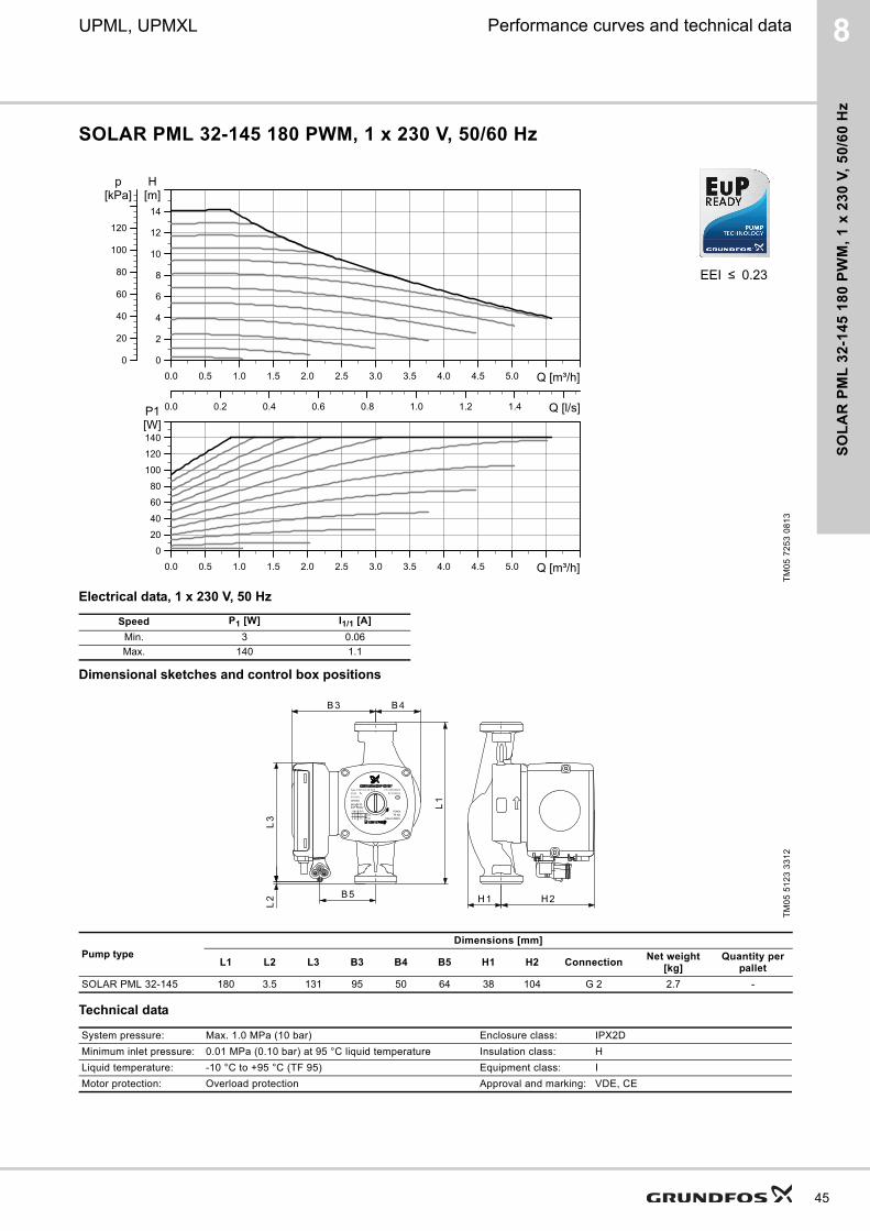
SOLAR PML 32-145 180 PWM, 1 x 230 V, 50/60 Hz
Electrical data, 1 x 230 V, 50 Hz
Dimensional sketches and control box positions
Technical data
TM
05
72
53
08
13
Speed P1 [W] I1/1 [A]
Min. 3 0.06
Max. 140 1.1
TM
05
51
23
33
12
Pump typeDimensions [mm]
L1 L2 L3 B3 B4 B5 H1 H2 ConnectionNet weight
[kg]Quantity per
pallet
SOLAR PML 32-145 180 3.5 131 95 50 64 38 104 G 2 2.7 -
System pressure: Max. 1.0 MPa (10 bar) Enclosure class: IPX2D
Minimum inlet pressure: 0.01 MPa (0.10 bar) at 95 °C liquid temperature Insulation class: H
Liquid temperature: -10 °C to +95 °C (TF 95) Equipment class: I
Motor protection: Overload protection Approval and marking: VDE, CE
EEI ≤ 0.23
0.0 0.5 1.0 1.5 2.0 2.5 3.0 3.5 4.0 4.5 5.0 Q [m³/h]
0
2
4
6
8
10
12
14
[m]H
0
20
40
60
80
100
120
[kPa]p
0.0 0.2 0.4 0.6 0.8 1.0 1.2 1.4 Q [l/s]
0.0 0.5 1.0 1.5 2.0 2.5 3.0 3.5 4.0 4.5 5.0 Q [m³/h]
0
20
40
60
80
100
120
140[W]P1
45

Te
ch
nic
al d
ata
46
UPML, UPMXL9
9. Technical data
Supply voltage
1 x 230 V + 10 %/- 15 %, 45-65 Hz.
Motor protection
The pump requires no external motor protection
Enclosure class
IPX2D
Appliance class
Class I
Insulation class
H
Ambient temperature
(Near pump surface)
Maximum +55 °C.
Temperature class
TF 95 according to EN 60335-2-51.
Liquid temperature
Maximum (continuously): +95 °C.
Short periods or low load: +110 °C.
Minimum: -10 °C (see validated temperature profile).
Storage temperature
Maximum 70 °C.
Maximum system pressure
1.0 MPa (10 bar).
EMC (electromagnetic compatibility)
• EN61000-6-2
• EN61000-6-3
• EN61000-3-2
• EN61000-3-3
• EN55014-1
• EN55014-2.
Overtemperature protection
UPML AUTO, UPMXL AUTO
To avoid overheating of the electronics inside the control box, the power will be derated by decreasing the speed, if necessary down to minimum speed without stopping the pump.
UPML, UPMXL PWM
In PWM pumps, an alarm will be sent with the feedback signal. At decreased temperature, the pump control will speed up again to normal operation.
Sound pressure level
The sound pressure level of the pump is lower than 38 dB(A).
Leakage current
The pump mains filter will cause a discharge current to earth during operation.
Ileakage < 3,5 mA.
Standby loss
Lower than 3 W.
NoteThe UPML GEO, UPMXL GEO are capable of handling a condensing environment.
Ambient temperature [°C]
Liquid temperature, max.[°C]
0 +95 (+110)
20 +95 (+110)
30 +95 (+110)
35 +95
40 +95
55 +75

Ap
pro
va
ls a
nd
ce
rtif
ica
tes
UPML, UPMXL 10
10. Approvals and certificates
EC declaration of conformityWe, Grundfos, declare under our sole responsibility that products GFJNB (UPML variants with PWM), GFJNC (UPML variants with user interface), GFJOC (UPMXL variants with user interface) and GFJOB (UPMXL variants with PWM), to which this declaration relates, are in conformity with these Council directives on the approximation of the laws of the EC member states:
Low Voltage Directive (2006/95/EC)
EMC Directive (2004/108/EC)
Ecodesign Directive (2009/125/EC)
Warning
The use of this product requires experience with and knowledge of the product. Persons with reduced physical,
sensory or mental capabilities must not use this product, unless they are under supervision or have been instructed in
the use of the product by a person responsible for their safety. Children must not use or play with this product.
Bjerringbro, 18th April 2013
Preben Jakobsen Technical Manager
Grundfos HVAC OEM Division
Grundfos Holding A/SPoul Due Jensens Vej 7
8850 Bjerringbro, Denmark
Person authorised to compile technical file and empowered to sign the EC declaration of conformity.
VDE certificateThese pumps are certified by VDE.
Product code:
This approval forms the basis of the EC declaration of conformity and the CE marking by the manufacturer or his agent and proves the conformity with the essential safety requirements of the EC Low Voltage Directive (2006/95/EC) including amendments.
Standards used: EN 60335-1:2012
EN 60335-2-51:2003 + A1.
Standards used: EN 61000-6-2:2005
EN 61000-6-3:2007
EN 55014-1:2006
EN 55014-2:1997.
EU regulations (EC) No 641/2009
(EC) No 622/2009
Standards used: EN 16297-1:2012
EN 16297-2:2012
EN 16297-3:2012
GFJNB: UPML (GEO) xx-105 PWM, SOLAR PML xx-145 PWM
GFJNC: UPML xx-95 AUTO
GFJOC: UPMXL xx-105 AUTO
GFJOB: UPMXL GEO xx-125 PWM
VDE certificate: No. 40037291.
47

Ap
pro
va
ls a
nd
ce
rtifica
tes
48
UPML, UPMXL10
REACH compliancy - Chemical Management - Grundfos Focus ListAt Grundfos, we run our business in a responsible and ever more sustainable way. We are committed to creating products and solutions that help our customers and the surrounding world conserve natural resources and reduce climate impacts. This is part of the Grundfos Values, as well as in accordance with the Grundfos Sustainability Strategy, which has the scope of reducing our chemical footprint and developing new sustainable products and solutions.
In order to give our suppliers, contractors and other relevant stakeholder world wide a tool to help comply with this, we have devised the Grundfos Focus List, which bans or restricts the use of chemical substances in Grundfos products, production processes and at Grundfos facilities.
This in turn means that all our various business partners at all times are obliged to follow the Grundfos Focus List and never deliver any products, processes or services containing any of the listed chemical substances.
The list has been developed on the basis of European chemical legislation such as the REACH regulation, RoHS, Battery, Packaging, ODS (Ozone Depleting Substances) and POPs (Persistent Organic Pollutants) directives.
Furthermore, we ban the Substances of Very High Concern (SVHC) from the REACH Candidate List (www.echa.europa.eu/web/guest/candidate-list-table).
Should a product contain SVHC from the Candidate List above 0.1 percent, this must be declared and a plan to phase out the SVHC within a year must be sent to Grundfos.
In situations, where local legislation is stricter than European chemical legislation, these demands will overrule the claims of the Focus List.
The valid Focus list is at all times available at www.grundfos.com/focus-list. However, users of the list are responsible for taking legal updates of the listed regulations into account.
With kind regards,
Torben Brændgaard
Group Environment Manager
Declaration concerning GRUNDFOS' compliance with RoHS and WEEE directiveGRUNDFOS Holding A/S and its subsidiaries accept their responsibilities and are committed not to use hazardous substances in their products. Grundfos products are not as of today in general covered by the WEEE- and RoHS-directives.
In regards to the RoHS directive (2002/95/EC) amended by directive (2011/65/EC) on the restriction of the use of certain hazardous substances in electrical and electronic equipment (EEE) latest in 2019 all EEE will as a starting point be affected.
However, Grundfos is now in complete voluntary RoHS-compliance concerning the non-use of the certain hazardous substance in GRUNDFOS products - see section about "Chemical Management - Grundfos Focus List".
In regards to the WEEE-directive (2002/96/EC) amended by directive (2012/19/EC) and its impact on pumps, Grundfos recommends reading the Europump position paper of 16 December 2005 which can be found on http://europump.net/publications/position-papers.
From 2018, all EEE will be within the scope of the WEEE-directive II, however several of the exemptions apply to many of Grundfos’ products and Grundfos will be working on the implementation of this towards 2018.
Yours faithfully,
GRUNDFOS Management A/S
Carsten Bjerg
Group President

49

50

51

GRUNDFOS A/S DK-8850 Bjerringbro . DenmarkTelephone: +45 87 50 14 00www.grundfos.com
98465581 0414
ECM: 1134366 Th
e n
am
e G
run
dfo
s, t
he
Gru
nd
fos
log
o,
an
d b
e t
hin
k i
nn
ov
ate
are
re
gis
tere
d t
rad
em
ark
s o
wn
ed
by
Gru
nd
fos
Ho
ldin
g A
/S o
r G
run
dfo
s A
/S,
De
nm
ark
. A
ll ri
gh
ts r
ese
rve
d w
orl
dw
ide
.©
Co
pyr
igh
t G
run
dfo
s H
old
ing
A/S