a 1 6 tm - schneider electric · a 1 6 display / adjustment options vw3-a16101, vw3-a16102,...
TRANSCRIPT

aaaa 11116666
Display / Adjustment Options
VW3-A16101, VW3-A16102,VW3-A16103
for ALTIVAR 16 Drive Controllers
Instruction Bulletin
50006-360-02B
May, 1995
Replaces 50006-360-02A dated 1/94
TM

50006-360-02BMay, 1996
© 1994 Schneider S.A. All Rights Reserved
Revision Notice
Display/Adjustment Options manufactured after March, 1994 (date code 9414) havethe addition of the
LLLLFFFFrrrr
parameter as described in this manual.
Trademark Notice
a
™ is a trademark of Square D.
Copyright Notice
© 1994 Square D. All rights reserved. This document may not be copied in whole orin part, or transferred to any other media, without the written permission of Square D.
Please Note
Electrical equipment should be serviced only by qualified electrical maintenance per-sonnel, and this document should not be viewed as sufficient instruction for those whoare not otherwise qualified to operate, service or maintain the equipment discussed.Although reasonable care has been taken to provide accurate and authoritative infor-mation in this document, no responsibility is assumed by Square D for any conse-quences arising out of the use of this material.
On earlier models, the DC bus terminals, designated J8- and J9+ in the BusVoltage Measurement Procedure, are designated as follows:
Catalog No. J8- J9+
ATV16U09M2J211 J212
ATV16U18M2
ATV16U29M2
J104 J105ATV16U18N4
ATV16U29N4
ATV16U41M2
J110 J112ATV16U41N4
ATV16U54N4
ATV16U72N4
NOTE

50006-360-02BMay, 1996 Table of Contents
© 1994 Schneider S.A. All Rights Reserved Page i
Introduction .......................................................................................................... 1VW3-A16101 .................................................................................................. 1VW3-A16102 ..................................................................................................2VW3-A16103 ..................................................................................................2
Mounting .............................................................................................................. 3Local ...............................................................................................................3Remote ...........................................................................................................4
Parameter Summary ............................................................................................5
Switch Settings .................................................................................................... 6Switch 1 (VW3-A16102 Only) .........................................................................6Switch 2 (VW3-A16101 and VW3-A16102) ....................................................6
Operation of the Push Buttons .............................................................................8Set-up Mode ...................................................................................................9Adjustment Lockout Mode ............................................................................10
Configuration Parameters ..................................................................................10
UUUUnnnnSSSS
: Nominal Motor Voltage .........................................................................10
FFFFrrrrSSSS
: Nominal Motor Frequency ....................................................................10
ttttFFFFrrrr
: Maximum Drive Output Frequency .......................................................11
UUUUFFFFtttt
: Type of Volts/Frequency Ratio .............................................................. 11
bbbbrrrrAAAA
: Deceleration Ramp Adaptation ............................................................12
SSSSLLLLPPPP
: Automatic Slip Compensation ..............................................................12
SSSSttttEEEE
: Start/Stop in Adjustment Lockout Mode ...............................................13
SSSSttttSSSS
: Start/Stop in Set-up Mode ....................................................................13
rrrrEEEESSSS
: Reset Fault ...........................................................................................13
Adjustment Parameters ......................................................................................14
AAAAcccccccc
: Acceleration Ramp Time ......................................................................14
ddddEEEEcccc
: Deceleration Ramp Time ......................................................................14
LLLLSSSSPPPP
: Low Speed ...........................................................................................15
KKKKSSSSPPPP
: High Speed ..........................................................................................15
UUUUFFFFrrrr
: Volts/Frequency Ratio .......................................................................... 15
FFFFLLLLGGGG
: Frequency Loop Gain ...........................................................................16
iiiitttthhhh
: Motor Thermal Protection..................................................................... 16
LLLLFFFF
rrrr
: Reference Frequency in Hz.................................................................. 17
Display Parameters ............................................................................................17
Additional Parameters ........................................................................................18VW3-A16201 Option Card set for General Use ............................................18VW3-A16201 Option Card Set for Material Handling ................................... 19VW3-A16202 Variable Torque Option Card ..................................................21VW3-A16203 High Speed Motor Option Card ..............................................22VW3-A16204 General Use / 3-Wire Control Option Card ............................ 23
Operation Assistance .........................................................................................24Procedure 1: Checking Supply Voltage ........................................................24
Bus Voltage Measurement Procedure ....................................................25Procedure 2: Checking the Peripheral Equipment ........................................26Fault Codes ..................................................................................................27

50006-360-02BList of Figures and Tables May, 1996
Page ii © 1994 Schneider S.A. All Rights Reserved
List of Figures
Figure 1 Display/Adjustment Option VW3-A16101 . . . . . . . . . . . . . . . . . . . . . .1Figure 2 Display/Adjustment/Local Control Option VW3-A16102 . . . . . . . . . . .2Figure 3 Mounting Option VW3-A16101 or VW3-A16102 . . . . . . . . . . . . . . . .3Figure 4 Remote Mounting with Kit VW3-A16103 . . . . . . . . . . . . . . . . . . . . . .4Figure 5 Parameter Summary . . . . . . . . . . . . . . . . . . . . . . . . . . . . . . . . . . . . . .5Figure 6 Set-up Mode . . . . . . . . . . . . . . . . . . . . . . . . . . . . . . . . . . . . . . . . . . . .9Figure 7 Adjustment Lockout Mode . . . . . . . . . . . . . . . . . . . . . . . . . . . . . . . .10Figure 8 Voltage/Frequency Operation . . . . . . . . . . . . . . . . . . . . . . . . . . . . . .11Figure 9 Deceleration Ramp Adaptation . . . . . . . . . . . . . . . . . . . . . . . . . . . . .12Figure 10 Automatic Slip Compensation . . . . . . . . . . . . . . . . . . . . . . . . . . . . . .12Figure 11 Acceleration Ramp . . . . . . . . . . . . . . . . . . . . . . . . . . . . . . . . . . . . . .14Figure 12 Deceleration Ramp . . . . . . . . . . . . . . . . . . . . . . . . . . . . . . . . . . . . . .14Figure 13 Low Speed/High Speed . . . . . . . . . . . . . . . . . . . . . . . . . . . . . . . . . .15Figure 14 Volts/Frequency Ratio . . . . . . . . . . . . . . . . . . . . . . . . . . . . . . . . . . .15Figure 15 Preset Speeds . . . . . . . . . . . . . . . . . . . . . . . . . . . . . . . . . . . . . . . . .19Figure 16 Brake Control Logic . . . . . . . . . . . . . . . . . . . . . . . . . . . . . . . . . . . . .20Figure 17 Measuring Bus Capacitor Voltage . . . . . . . . . . . . . . . . . . . . . . . . . .25
List of Tables
Table 1 Set-Up Mode . . . . . . . . . . . . . . . . . . . . . . . . . . . . . . . . . . . . . . . . . . . 7Table 2 Adjustment Lockout Mode . . . . . . . . . . . . . . . . . . . . . . . . . . . . . . . . .7Table 3 Key Operation . . . . . . . . . . . . . . . . . . . . . . . . . . . . . . . . . . . . . . . . . . .8Table 4 Nominal Motor Voltage Settings . . . . . . . . . . . . . . . . . . . . . . . . . . . .10Table 5 Fault Codes . . . . . . . . . . . . . . . . . . . . . . . . . . . . . . . . . . . . . . . . . . .27

50006-360-02B Display/Adjustment OptionsMay, 1996 Introduction
© 1994 Schneider S.A. All Rights Reserved Page 1
INTRODUCTION
This instruction bulletin covers installation and operation of the three Display/Adjust-ment options available for use with the Altivar 16 family of drive controllers:
• VW3-A16101: Display/Adjustment Option
• VW3-A16102: Display/Adjustment/Local Control Option
• VW3-A16103: Remote Mounting Kit
It also describes the various parameters and fault codes accessible with the options.Each option is described in the following sections.
VW3-A16101
Option VW3-A16101 mounts on the front of the drive controller. It includes three sev-en-segment displays, one program LED, and four push buttons for programming thedrive controller. Its features are illustrated in Figure 1.
For a summary of the parameters accessible with this and the other two display op-tions, see Figure 5 on page 5. The codes displayed in the event of a fault are listed inTable 5 on page 27.
Figure 1 Display/Adjustment Option VW3-A16101
BACK
FRONT
1-line, 3-character 7-segment display
Scroll forward push button
Scroll backward push button
Program LED
Data push button
Program push button
Switches for selecting modes
PROGDATA
PROG
21
ON
888

Display/Adjustment Options 50006-360-02BVW3-A16102 / -A16103 May, 1996
Page 2 © 1994 Schneider S.A. All Rights Reserved
VW3-A16102
Option VW3-A16102 also mounts on the front of the drive controller. It provides thesame features as option VW3-A16101, but adds the ability to start and stop the drivecontroller from the option if a direction command (FW/RV) is present, and the abilityto adjust the speed of the drive controller and to reset the drive controller from the op-tion. LEDs indicate when the drive is in local control and whether the motor has beencommanded to rotate in forward or reverse. Option VW3-A16102 is illustrated in Fig-ure 2.
Figure 2 Display/Adjustment/Local Control Option VW3-A16102
VW3-A16103
Option VW3-A16103 is a kit for remote mounting of option VW3-A16101 or VW3-A16102 to a NEMA Type 1, 4 or 12 enclosure. The kit consists of an interface boxwhich mounts on the front of the drive controller, a 3-meter connection cable and aplastic keypad cover.
PROGDATA
FWD
STARTSTOPRESET
REVLOCALPROG
21
ON
888
BACK
FRONT1-line, 3-character 7-segment display
Scroll forward push button
Scroll backward push button
Program LED
Data push button
Program push button
Switches for selecting modes
Local command LED
Forward run LED
Reverse run LED
Stop/Reset push button
Start push button

50006-360-02B Display/Adjustment OptionsMay, 1996 Local Mounting
© 1994 Schneider S.A. All Rights Reserved Page 3
MOUNTING
Local
Options VW3-A16101 and VW3-A16102 can be connected while the drive controlleris powered up. To mount either option (refer to Figure 3):
1. Using a screwdriver, remove programming cover plate from front of drivecontroller as shown. Do not remove any other cover.
2. Plug option into drive controller. Use screwdriver to secure option.
Note:
Removal of option VW3-A16102 when it is set to local mode (Switch 1 set toOn, see page 6) and when the drive controller is powered up (with or without the mo-tor running) will cause the drive controller to fault.
Figure 3 Mounting Option VW3-A16101 or VW3-A16102
HAZARDOUS VOLTAGE.
Do not remove any other cover besides programming cover plate when installing the option.
Failure to observe this precaution can cause shock or burn, resulting in severe personal injury or death.
! WARNING
DATAPROG
DATAPROG
STOP
START
RESET
VW3-A16101VW3-A16102
or
1
ProgrammingCover Plate
2
Display/Adjustment Options 50006-360-02BRemote Mounting May, 1996
Page 4 © 1994 Schneider S.A. All Rights Reserved
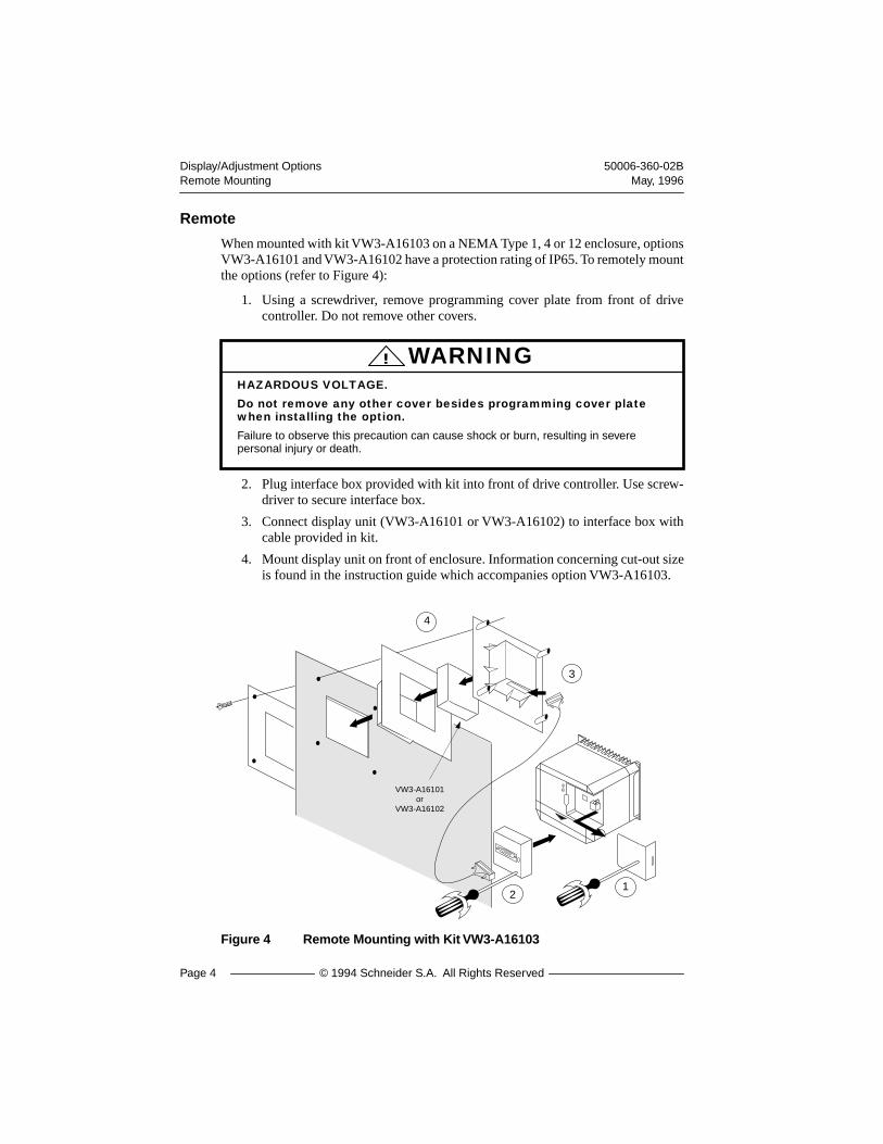
Remote
When mounted with kit VW3-A16103 on a NEMA Type 1, 4 or 12 enclosure, optionsVW3-A16101 and VW3-A16102 have a protection rating of IP65. To remotely mountthe options (refer to Figure 4):
1. Using a screwdriver, remove programming cover plate from front of drivecontroller. Do not remove other covers.
2. Plug interface box provided with kit into front of drive controller. Use screw-driver to secure interface box.
3. Connect display unit (VW3-A16101 or VW3-A16102) to interface box withcable provided in kit.
4. Mount display unit on front of enclosure. Information concerning cut-out sizeis found in the instruction guide which accompanies option VW3-A16103.
Figure 4 Remote Mounting with Kit VW3-A16103
HAZARDOUS VOLTAGE.
Do not remove any other cover besides programming cover plate when installing the option.
Failure to observe this precaution can cause shock or burn, resulting in severe personal injury or death.
! WARNING
VW3-A16101or
VW3-A16102
12
3
4

50006-360-02B Display/Adjustment OptionsMay, 1996 Parameter Summary
© 1994 Schneider S.A. All Rights Reserved Page 5
PARAMETER SUMMARY
Figure 5 lists the parameters accessible through the Display/Adjustment optionsalong with their valid ranges.
Figure 5 Parameter Summary
Note:
Value of input line voltage,
UUUULLLLnnnn
,
is valid only when the drive controller is inready mode
(
rrrrddddyyyy
).
In addition, the value displayed may be incorrect if the input linevoltage is subject to waveform distortion.
High speedLSP to tFr
Volts/frequency ratio 0 to 100
Frequency loop gain0 to 99 , nFL
Motor overload thermal protection 0.45 to 1.05 times In
Volts/frequency ratioN / P / L
Maximum frequency 40 to 200 Hz
Nominal motor frequency40 to 200 Hz
Nominal motorvoltage380-400-415-460V208-220-230-240VAccording to rating(N4 - M2)
Display parameters (electrical quantities):displayed in Adjustment Lockout modenot adjustable
Adjustment parameters: displayed in Adjustment Lockout mode adjustable in Set-up mode
Configuration parameters: displayed and adjustable in Set-up mode
Drive ready
Frequency reference
Motor current
Input line voltage
Acceleration time0.1 to 600 s
Deceleration time0.1 to 600 s
Low speed0 to HSP
*
*
*
Fault Reset functionon/ off
Stop / Start function in Set-up modeon/ off
Stop / Start functionin AdjustmentLockout mode on/ off
Slip compensationon / off
Deceleration rampadaptationon / off
* Only on VW3-A16102
rES
StS
StE
SLP
brA
UFt
tFr
FrS
UnS
Acc
dEc
LSP
HSP
UFr
FLG
ItH
FrH
Lcr
ULn
Adjustment parameter LFr(option VW3-A16102 only): displayed and adjustable in Adjustment Lockout and Set-up modes when in Local command
LFr
rdY
*
Display/Adjustment Options 50006-360-02BSwitch Settings May, 1996
Page 6 © 1994 Schneider S.A. All Rights Reserved
SWITCH SETTINGS
Use the switches on back of the Display/Adjustment options as described in the fol-lowing sections. Refer to Tables 1 and 2 for a summary of switch settings.
For location of the switches on option VW3-A16101, see Figure 1 on page 1. For lo-cation of switches on option VW3-A16102, see Figure 2 on page 2.
Note:
In Table 1 and Table 2, Drive Ready indicates that power is applied to the drivecontroller, but no Run command is present
.
Switch 1 (VW3-A16102 Only)
Switch 1, used on option VW3-A16102
only
, selects local control. When Switch 1 isset to On, the drive controller is in Local mode. With the presence of a direction com-mand (FW/RV) and reference frequency set with the
LLLLFFFFrrrr
parameter, the drive con-troller may be started, stopped and reset from the Display/Adjustment option,depending on settings of the
rrrrEEEESSSS
,
SSSSttttSSSS
and
SSSSttttEEEE
parameters (see page 13).
When Switch 1 is set to Off, the drive controller is run only with the presence of adirection command (FW/RV) and reference signal at AIV or AIC.
Switch 2 (VW3-A16101 and VW3-A16102)
Switch 2 is used on both options to determine the mode of the Display/Adjustmentoption. When Switch 2 is set to On, the option is in
Set-up mode
. Set-up mode per-mits modification of parameters when the drive controller is ready or the motor is run-ning. See Table 1 for further explanation.
When Switch 2 is set to Off, the option is in
Adjustment Lockout mode
. No modi-fication of parameters is possible in this mode. See Table 2 for further explanation.
50006-360-02B Display/Adjustment OptionsMay, 1996 Switch Settings
© 1994 Schneider S.A. All Rights Reserved Page 7
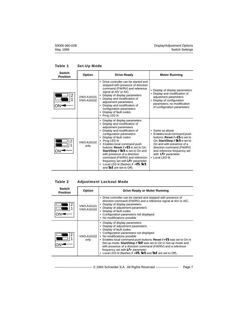
Table 1 Set-Up Mode
Switch Position Option Drive Ready Motor Running
VW3-A16101 VW3-A16102
• Drive controller can be started and stopped with presence of direction command (FW/RV) and reference signal at AIV or AIC.
• Display of display parameters• Display and modification of
adjustment parameters • Display and modification of
configuration parameters• Display of fault codes• Prog LED lit
• Display of display parameters• Display and modification of
adjustment parameters• Display of configuration
parameters; no modification of configuration parameters
VW3-A16102only
• Display of display parameters• Display and modification of
adjustment parameters • Display and modification of
configuration parameters• Display of fault codes• Prog LED lit• Enables local command push
buttons:
Reset
if
RRRREEEESSSS
is set to On.
Start/Stop
if
SSSSttttSSSS
is set to On and with presence of a direction command (FW/RV) and reference frequency set with
LLLLFFFFrrrr
parameter.• Local LED lit (flashes if
rrrrEEEESSSS
,
SSSSttttSSSS
and
SSSSttttEEEE
are set to Off).
• Same as above• Enables local command push
buttons:
Reset
if
RRRREEEESSSS
is set to On.
Start/Stop
if
SSSSttttSSSS
is set to On and with presence of a direction command (FW/RV) and reference frequency set with
LLLLFFFFrrrr
parameter.• Local LED lit.
Table 2 Adjustment Lockout Mode
Switch Position Option Drive Ready or Motor Running
VW3-A16101 VW3-A16102
• Drive controller can be started and stopped with presence of direction command (FW/RV) and a reference signal at AIV or AIC.
• Display of display parameters• Display of adjustment parameters• Display of fault codes• Configuration parameters not displayed• No modifications possible
VW3-A16102only
• Display of display parameters• Display of adjustment parameters• Display of fault codes• Configuration parameters not displayed• No modifications possible• Enables local command push buttons:
Reset
if
rrrrEEEESSSS
was set to On in Set-up mode.
Start/Stop
if
SSSSttttEEEE
was set to On in Set-up mode and with presence of a direction command (FW/RV) and a reference frequency set with
LLLLFFFFrrrr
parameter. • Local LED lit (flashes if
rrrrEEEESSSS
,
SSSSttttSSSS
and
SSSSttttEEEE
are set to Off).
ON
21
ON
21
ON
21
ON
12

Display/Adjustment Options 50006-360-02BPush Button Operation May, 1996
Page 8 © 1994 Schneider S.A. All Rights Reserved
OPERATION OF THE PUSH BUTTONS
Figures 6 and 7 illustrate operation of the Display/Adjustment option push buttons.Refer to Table 3 for key operation. For key operation with the
LLLLFFFFrrrr
parameter, referto page 17.
Table 3 Key Operation
Operation
Key
When parameter name is displayed When parameter value is displayed
Steps forward through list of parameters Increases parameter value
Steps back through list of parameters Decreases parameter value
Displays parameter value Displays parameter name or cancels change to parameter value
Saves change to parameter value
DATA
PROG

50006-360-02B Display/Adjustment OptionsMay, 1996 Push Button Operation
© 1994 Schneider S.A. All Rights Reserved Page 9
Set-up Mode
Figure 6 illustrates how to change and save adjustment and configuration parametervalues in Set-up mode (Switch 2 set to On).
Figure 6 Set-up Mode
DATA
PROG
DATA
DATA
Call up ofthe
parameterto be
modified
Modificationof the
adjustmentor
configurationparameter
ItH
400
415
460
UnS
FrS
UnS
460
PROG LED lit:set-up mode.
PROG LED flashing (VW3-A16102):waiting for acceptance of selection.To accept value displayed, pressPROG push button. To reject valuedisplayed, press DATA push button. Value displayed takes effect when PROG push button is pressed.
PROG
PROG
4.0 0Decimal point flashing (VW3-A16101) or
Display/Adjustment Options 50006-360-02BConfiguration Parameters May, 1996
Page 10 © 1994 Schneider S.A. All Rights Reserved
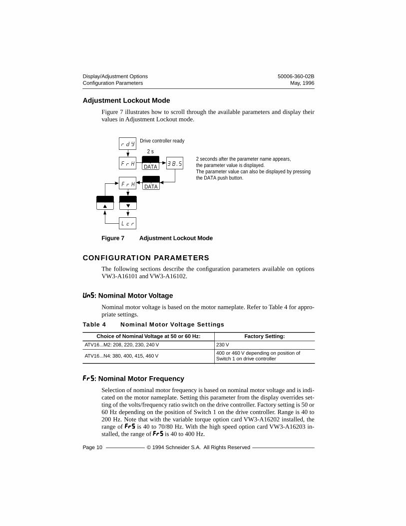
Adjustment Lockout Mode
Figure 7 illustrates how to scroll through the available parameters and display theirvalues in Adjustment Lockout mode.
Figure 7 Adjustment Lockout Mode
CONFIGURATION PARAMETERS
The following sections describe the configuration parameters available on optionsVW3-A16101 and VW3-A16102.
UUUUnnnnSSSS
: Nominal Motor Voltage
Nominal motor voltage is based on the motor nameplate. Refer to Table 4 for appro-priate settings.
FFFFrrrrSSSS
: Nominal Motor Frequency
Selection of nominal motor frequency is based on nominal motor voltage and is indi-cated on the motor nameplate. Setting this parameter from the display overrides set-ting of the volts/frequency ratio switch on the drive controller. Factory setting is 50 or60 Hz depending on the position of Switch 1 on the drive controller. Range is 40 to200 Hz. Note that with the variable torque option card VW3-A16202 installed, therange of
FFFFrrrrSSSS
is 40 to 70/80 Hz. With the high speed option card VW3-A16203 in-stalled, the range of
FFFFrrrrSSSS
is 40 to 400 Hz.
Table 4 Nominal Motor Voltage Settings
Choice of Nominal Voltage at 50 or 60 Hz: Factory Setting:
ATV16...M2: 208, 220, 230, 240 V 230 V
ATV16...N4: 380, 400, 415, 460 V 400 or 460 V depending on position of Switch 1 on drive controller
DATA
Drive controller ready
2 seconds after the parameter name appears, the parameter value is displayed. The parameter value can also be displayed by pressingthe DATA push button.
rdY
FrH
FrH
Lcr
38.5DATA
2 s

50006-360-02B Display/Adjustment OptionsMay, 1996 Configuration Parameters
© 1994 Schneider S.A. All Rights Reserved Page 11
Note
: For drive controllers containing V2.1, IE07 or later software, the position ofswitch 1 on the control board determines whether the drive controller is 2-wire con-trol (Switch 1 set for 50 Hz) or 2-wire transitional control (Switch 1 set for 60 Hz).The setting of the
FrS
parameter does not affect the type of control. For more infor-mation, see the drive controller instruction bulletin 50006-360-01.
ttttFFFFrrrr: Maximum Drive Output Frequency
Overspeed operation at constant power above nominal motor frequency follows thecharacteristics shown in Figure 8. Factory setting is 50 Hz if FFFFrrrrSSSS=50, or 60 Hz ifFFFFrrrrSSSS=60. Maximum drive output frequency can range from 40 to 200 Hz. Note thatwith the variable torque option card VW3-A16202 installed, the range of ttttFFFFrrrr is 40 to70/80 Hz. With the high speed option card VW3-A16203 installed, the range of ttttFFFFrrrris 40 to 400 Hz.
Figure 8 Voltage/Frequency Operation
UUUUFFFFtttt: Type of Volts/Frequency Ratio
UUUUFFFFtttt is used along with UUUUFFFFrrrr to give voltage boost. Refer to Figure 14 on page 15 forthe V/f curves. Possible settings are n, L or P.
• n: Volts/frequency ratio adjusted for constant torque applications (ma-chines with average loads) not requiring high voltage boost.
• L: Volts/frequency ratio adjusted for constant torque applications for spe-cial motors (tapered rotor motors, pole change motors, high torque mo-tors) used in fast cycle applications.
• P: Volts/frequency ratio adjusted for quadratic torque applications such asfans or centrifugal pumps.
- 460
40 200
- 240- 415
- 230- 400
- 220- 380
- 208
M2N4 Volts (V)
Frequency (Hz)
UnS
tFr
FrS
Range of
Range of
Display/Adjustment Options 50006-360-02BConfiguration Parameters May, 1996
Page 12 © 1994 Schneider S.A. All Rights Reserved
bbbbrrrrAAAA: Deceleration Ramp Adaptation
Possible settings are On and Off.
Figure 9 Deceleration Ramp Adaptation
SSSSLLLLPPPP: Automatic Slip Compensation
Possible settings are On and Off.
Figure 10 Automatic Slip Compensation
On: Deceleration ramp time (ddddEEEEcccc) is automatically adjusted to compensate for load inertia and to avoid overbraking fault (0000bbbbFFFF).
Off: Deceleration ramp time (ddddEEEEcccc) is not automatically adjusted. If the motor is unable to follow deceleration ramp, drive controller will trip on overbraking fault (0000bbbbFFFF).
On
Off
t
Speed
Off: Automatic slip compensation disabled. Use this setting for applications with high inertia, variable torque or external speed regulation.
On: Automatic slip compensation enabled. Use this setting for running at constant speed as the load changes.
T
T
TorqueLimit
TorqueLimit
Speed
Speed
Set Point
Set Point
Increasing Torque
Increasing Torque

50006-360-02B Display/Adjustment OptionsMay, 1996 Configuration Parameters
© 1994 Schneider S.A. All Rights Reserved Page 13
SSSSttttEEEE, SSSSttttSSSS, rrrrEEEESSSS
Three additional configuration parameters are available with option VW3-A16102.These are used to start, stop and reset the drive controller from the display optionwhen in Local mode (Switch 1 set to On) and when a direction command (FW/RV)and reference frequency set with LLLLFFFFrrrr are present. When not in Local mode (Switch 1set to Off), these parameters are not used and the drive controller is run with the pres-ence of a direction command and reference signal at AIV or AIC.
SSSSttttEEEE: Start/Stop in Adjustment Lockout Mode
When SSSSttttEEEE is set to On and the display is in Adjustment Lockout mode, with the pres-ence of a direction command (FW/RV) and a reference frequency set with LLLLFFFFrrrr, thedrive controller is started and stopped from the display option. When a direction com-mand is present, the FWD or REV LED will flash to indicate that the drive controllercan be started from the display option. When started, the FWD or REV LED will belit. If the direction command is removed while the drive controller is running, thedrive controller will stop. If a direction command (FW or RV) is restored, the drivecontroller will restart. When SSSSttttEEEE is set to Off and the display is in Adjustment Lock-out mode, the drive controller cannot be started even if a direction command and ref-erence frequency are present.
SSSSttttSSSS: Start/Stop in Set-up Mode
When SSSSttttSSSS is set to On and the display is in Set-up mode, with the presence of a di-rection command (FW/RV) and reference frequency set with LLLLFFFFrrrr, the drive controlleris started and stopped from the display option. When a direction command is present,the FWD or REV LED will flash to indicate that the drive controller can be startedfrom the display option. When started, the FWD or REV LED will be lit. If the direc-tion command is removed while the drive controller is running, the drive controllerwill stop. If a direction command (FW or RV) is restored, the drive controller will re-start. When SSSSttttSSSS is set to Off and the display is in Set-up mode, the drive controllercannot be started, even if a direction command and reference frequency are present.
rrrrEEEESSSS: Reset Fault
The reset fault function is not dependent on whether the display option is in Adjust-ment Lockout or Set-up mode. When rrrrEEEESSSS is set to On, the drive controller can be resetafter the 0000SSSSFFFF, 0000LLLLFFFF, 00008888FFFF, 00008888FFFF.... , SSSSPPPPFFFF, SSSSPPPPFFFF.... or SSSSLLLLFFFF faults (see pages 23 and 24) by press-ing the Stop/Reset push button, if the cause of the fault has been corrected. When rrrrEEEESSSSis set to Off, after these faults the drive controller must be reset by removing power.If the cause of the PPPPHHHHFFFF, UUUUSSSSFFFF or 0000pppptttt faults is corrected, the drive controller automati-cally resets.
Display/Adjustment Options 50006-360-02BAdjustment Parameters May, 1996
Page 14 © 1994 Schneider S.A. All Rights Reserved
ADJUSTMENT PARAMETERSThe following sections describe the adjustment parameters available on both optionsVW3-A16101 and VW3-A16102.
AAAAcccccccc: Acceleration Ramp Time
Acceleration ramp time can range from 0.1 to 600 s. The factory setting is 3 s. Accel-eration ramp time is automatically extended when the maximum transient output cur-rent of the drive controller is reached.
Figure 11 Acceleration Ramp
ddddEEEEcccc: Deceleration Ramp Time
Deceleration ramp time can range from 0.1 to 600 s. The factory setting is 3 s. If de-celeration ramp adaptation (bbbbrrrrAAAA) is set to On, the deceleration time is automaticallyextended to avoid overbraking fault (0000bbbbFFFF).
Figure 12 Deceleration Ramp
60 Hz
0
f
t0.1 to 600 s
(50 Hz)
Acc
0
f
t0.1 to 600 s
60 Hz(50 Hz)
dEC

50006-360-02B Display/Adjustment OptionsMay, 1996 Adjustment Parameters
© 1994 Schneider S.A. All Rights Reserved Page 15
LLLLSSSSPPPP: Low SpeedKKKKSSSSPPPP: High Speed
The factory settings for low speed (LLLLSSSSPPPP) and high speed (XXXXSSSSPPPP) are 0 Hz and 50 Hzrespectively. When LLLLSSSSPPPP is 0, the drive stays ready as long as reference speed is lessthan 0.1 Hz. XXXXSSSSPPPP is limited by the value of maximum drive output frequency (ttttFFFFrrrr).
Figure 13 Low Speed/High Speed
UUUUFFFFrrrr: Volts/Frequency Ratio
UUUUFFFFrrrr is factory set to nnnn22220000, LLLL22220000 or PPPP22220000, depending on the setting of UUUUFFFFtttt (i.e, n, P orL). The factory settings are suitable for most applications; however, if the torque isinsufficient, increase the setting gradually from 00000000 to 111100000000.
Figure 14 Volts/Frequency Ratio
f(Hz)
tFr
LSP
0 (2)0 (4)
10V20 mA
HSP
UnS
VUnS
VUnS
V P
F (Hz)F (Hz)
n
00
99
F (Hz) 00
99
00
99
L
FrS FrS FrS
Display/Adjustment Options 50006-360-02BAdjustment Parameters May, 1996
Page 16 © 1994 Schneider S.A. All Rights Reserved
FFFFLLLLGGGG: Frequency Loop Gain
Frequency loop gain can range from 00000000 to 99999999 or nnnnFFFFLLLL. The factory setting is 33333333. Formachines with high resistant torque or high inertia, reduce the gain gradually to a val-ue between 33333333 and 00000000. For machines with fast cycles, low resistant torque or low in-ertia, increase the gain gradually from 33333333 to 99999999. Note that too much gain can causeinstability. A value of nnnnFFFFLLLL suppresses frequency loop gain. This can cause the motorto stall if the required torque is too high.
iiiitttthhhh: Motor Thermal Protection
Motor thermal protection can range from 0.45 to 1.05 times the nominal drive con-troller rated output current. Factory setting is 0.9 times the drive controller rated out-put current. Adjust IIIIttttHHHH to the current value shown on the motor nameplate. Tosuppress motor thermal protection, increase the value of IIIIttttHHHH to the maximum andprovide external thermal protection.
MOTOR MAY STALL.
Inhibiting this function can cause motor to stall if required torque is too high.
Failure to observe this precaution can result in equipment damage.
! CAUTION
LOSS OF MOTOR OVERLOAD PROTECTION.
When using external overload relays connected to the drive controller output, the overload relay must be capable of operation over the expected range of drive controller output frequencies (including direct current).
When DC injection braking is used:
• The overload relay must be suitable for operation with direct current flowing in the motor.
• Do not use overload relays equipped with current transformers for sensing the motor current.
Failure to observe this precaution can result in equipment damage.
! CAUTION

50006-360-02B Display/Adjustment OptionsMay, 1996 Display Parameters
© 1994 Schneider S.A. All Rights Reserved Page 17
LLLLFFFFrrrr: Reference Frequency in Hz
When the display/adjustment keypad is in local command mode (Switch 1 On), thisparameter appears in place of FFFFrrrrHHHH and is used to adjust the reference frequency. InSet-up mode, SSSSttttSSSS must be set to On and in Adjustment Lockout mode, SSSSttttEEEE must beset to On for this parameter to take effect. To change the value of LLLLFFFFrrrr, press and or simultaneously. If the motor is running, the change is immediate-ly taken into account.
DISPLAY PARAMETERSThe values of the Display parameters, available on both option VW3-A16101 andVW3-A16102, are obtained by pressing the DATA push button.
• rrrrddddyyyy: Drive ready (no run command)
• FFFFrrrrHHHH: Reference frequency in Hz. If the displayed value flashes, it is be-cause the drive is adjusting its acceleration or deceleration ramp, or be-cause the drive is at current limit.
• LLLLccccrrrr: Motor current in Amps
• UUUULLLLnnnn: Input line voltage in volts
MOTOR OVERHEATING.
This drive controller does not provide direct thermal protection for the motor. Use of a thermal sensor in the motor may be required for protection at all speeds and loading conditions. Consult motor manufacturer for thermal capability of motor when operated over desired speed range.
Failure to observe this precaution can result in equipment damage.
! CAUTION
PROG

Display/Adjustment Options 50006-360-02BAdditional Parameters May, 1996
Page 18 © 1994 Schneider S.A. All Rights Reserved
ADDITIONAL PARAMETERSAdditional parameters appear on the display with the option cards. These are de-scribed in the following sections.
VW3-A16201 Option Card set for General Use
Adjustable Parameter
JJJJoooogggg: Jog operation. The LI3 input on the VW3-A16201 option card is factory set forJog operation when the option card is configured for general use. With LI3 at state 1,the direction command (FW/RV) input is used to jog the drive controller at the fre-quency set by the Jog parameter. Factory set for 5 Hz, it can be adjusted between 0.1and 10 Hz. When jogging, the acceleration and deceleration ramp rates are 0.1 s.
Configurable Parameters
AAAAttttrrrr: Automatic restart. Enables the drive controller to automatically restart follow-ing an overvoltage (0000SSSSFFFF), overload (0000LLLLFFFF) or overbraking (0000bbbbFFFF) fault. For the 0000SSSSFFFF and0000bbbbFFFFfaults, the drive controller remains disabled for 1 minute after the fault appearscausing the fault relay of the drive controller to engage, then it restarts automaticallyif the fault has disappeared. If the cause of the fault is present at the end of 1 minute,the drive controller must be manually reset. The drive controller will attempt five au-tomatic restarts (one every minute) before it must be manually reset. For the 0000LLLLFFFFfault, the restart is effective as soon as the thermal state drops below 100%, usuallyabout seven minutes after the fault occurs. Factory set to Off, can be configured toOn.
FFFFLLLLrrrr: Catching a spinning load. Allows smooth restarting of motor after a brief inputline undervoltage. If the reference signal and a direction command are maintained, themotor accelerates back up to speed without starting at zero. Factory set to Off, can beconfigured to On.
UNINTENDED EQUIPMENT ACTION.
• Automatic restart and catching a spinning load can only be used for machines or installations that present no danger in the event of automatic restarting, either for personnel or equipment.
• Equipment operation must conform with national and local safety regulations.
Failure to observe these precautions can result in equipment damage or severe personal injury.
! WARNING

50006-360-02B Display/Adjustment OptionsMay, 1996 Additional Parameters
© 1994 Schneider S.A. All Rights Reserved Page 19
VW3-A16201 Option Card Set for Material Handling
Configurable Parameter
SSSSttttPPPP: Controlled stop on loss of input power. Factory set to Off, can be configuredto On. When set to On, deceleration follows a self-adjusting ramp which is a functionof the regenerated energy. When set to Off, motor coasts to a stop at loss of input pow-er.
Adjustable Functions
Preset speeds: Preset Speed 1 is Low Speed (LLLLSSSSPPPP) or the value of the reference signal.Preset Speed 2 is High Speed (XXXXSSSSPPPP). The display allows adjustment of Preset Speeds3 and 4.
3333SSSSPPPP: Preset Speed 3. Input LI2 is factory set for Preset Speed 3. The drive controllerwill run at Preset Speed 3 when LI2 is at state 1 and a direction command is present(FWD or REV). Factory set at 5 Hz, Preset Speed 3 can be adjusted between LLLLSSSSPPPPand XXXXSSSSPPPP.
4444SSSSPPPP: Preset Speed 4. Input LI3 is factory set for Preset Speed 4. The drive controllerwill run at Preset Speed 4 when LI3 is at state 1 and a direction command (FWD orREV) is present. Factory set at 25 Hz, Preset Speed 4 can be adjusted to a value be-tween LLLLSSSSPPPP and XXXXSSSSPPPP.
Figure 15 Preset Speeds
t
t
t
t
01
LI2
0FW (RV)1
0LI3
1
LSP
HSP
f
4SP
3SP

Display/Adjustment Options 50006-360-02BAdditional Parameters May, 1996
Page 20 © 1994 Schneider S.A. All Rights Reserved
Brake control: The S2A-S2B relay on the VW3-A16201 option card is set for brakecontrol. The release and engaging of the mechanical brake follows the graph below.When the brake release frequency threshold and the brake release current threshold(1111bbbbrrrr) are reached, the S2A-S2B relay closes. During a time delay of t1, the acceler-ation ramp is inhibited. This ensures that the motor develops the necessary torque be-fore the actual release of the brake. For the brake to engage, when the decelerationramp reaches the brake engage frequency threshold, the S2A-S2B relay opens. Thebrake engages after a time delay of t1.
Figure 16 Brake Control Logic
1111bbbbrrrr: Brake release current threshold. Current threshold initiates closing of S2A-S2Bbrake control relay activating the brake release. Factory set to 0, brake release currentthreshold can be adjusted from 0 to 1.05 drive controller rated output current.
1
0
1
0
I
f
1
0
t
t
t
t
t
t
t1 t1
Brake state
S2A-S2B
Brake releasecurrent threshold (IBr)
Brake release frequency threshold
Brake engage frequency threshold
FW (RV)
Speed
Factory settings:Brake release frequency threshold = Low speed setting (LLLLSSSSPPPP)Brake release current threshold (1111bbbbrrrr) = 0. See 1111bbbbrrrr below.Brake release time delay = 0 sBrake engage frequency threshold = Low speed setting (LLLLSSSSPPPP)
50006-360-02B Display/Adjustment OptionsMay, 1996 Additional Parameters
© 1994 Schneider S.A. All Rights Reserved Page 21
VW3-A16202 Variable Torque Option Card
Adjustable Parameters
JJJJFFFF1111: Jump (skip) frequency 1 with bandwidth of 2 Hz. Factory set at 0 Hz (not used);can be adjusted to a value between LLLLSSSSPPPP and XXXXSSSSPPPP.
JJJJFFFF2222: Jump (skip) frequency 2 with bandwidth of 2 Hz. Factory set at 0 Hz (not used),can be adjusted to a value between LLLLSSSSPPPP and XXXXSSSSPPPP.
Configurable Parameters
AAAAttttrrrr: Automatic restart. Enables the drive controller to automatically restart follow-ing an overvoltage (0000SSSSFFFF), overload (0000LLLLFFFF) or overbraking (0000bbbbFFFF) fault. For the 0000SSSSFFFF and0000bbbbFFFFfaults, the drive controller remains disabled for 1 minute after the fault appears,causing the fault relay of the drive controller to engage, then it restarts automaticallyif the cause of the fault has disappeared. If the cause of the fault has not disappearedat the end of 1 minute, the drive controller must be manually reset. The drive control-ler will attempt 5 automatic restarts (one every minute) before it must be manuallyreset. For the 0000LLLLFFFF fault, the restart is effective as soon as the thermal state drops below100%, usually about 7 minutes after the fault occurs. Factory set to Off, can be con-figured to On.
FFFFLLLLrrrr:::: Catching a spinning load. Allows smooth restarting of the motor after a briefinput line undervoltage. If the reference signal and a direction command are main-tained, the motor accelerates back up to speed without starting at zero. Factory set toOff, can be configured to On.
SSSSttttPPPP: Controlled stop on loss of input power. Factory set to Off, can be configured toOn.When set to On, deceleration follows a self-adjusting ramp which is a function ofthe regenerated energy. When set to Off, motor coasts to a stop at loss of input power.
UNINTENDED EQUIPMENT ACTION.
• Automatic restart and catching a spinning load can only be used for machines or installations that present no danger in the event of automatic restarting, either for personnel or equipment.
• Equipment operation must conform with national and local safety regulations.
Failure to observe these precautions can result in equipment damage or severe personal injury.
! WARNING

Display/Adjustment Options 50006-360-02BAdditional Parameters May, 1996
Page 22 © 1994 Schneider S.A. All Rights Reserved
VW3-A16203 High Speed Motor Option Card
Adjustable Parameters
AAAAcccc2222: Acceleration ramp 2. LI2 is factory set as Switch to Ramp 2. When this inputis at state 1, drive controller will accelerate according to AAAAcccc2222. Factory set to 12 s, itcan be adjusted between 0.1 and 600 s.
ddddEEEE2222: Deceleration ramp 2. LI2 is factory set as Switch to Ramp 2. When this inputis at state 1, drive controller will decelerate according to ddddEEEE2222. Factory set to 12 s, itcan be adjusted between 0.1 and 600 s.
iiiiddddcccc: DC current level. DC injection occurs when frequency drops to a value lessthan 0.1 Hz. Factory set to 0.7 times IIIItttthhhh, it can be adjusted between 0.5 and 1.5 timesIIIItttthhhh.
ttttddddcccc:::: DC current time. Amount of time for which DC is injected when frequencydrops to a value less than 0.1 Hz. Factory set at 0.5 s, it can be adjusted from 0 to 5 sor to be permanently injected (setting is ddddccccbbbb).
FFFFLLLLrrrr:::: Catching a spinning load. Allows smooth restarting of the motor after a briefinput line undervoltage. If the reference signal and a direction command are main-tained, the motor accelerates back up to speed without starting at zero. Factory set toOff, can be configured to On.
NO HOLDING TORQUE.
• DC injection braking does not provide holding torque at zero speed.
• DC injection braking does not function during loss of power or drive controller fault.
When required, use separate brake function for holding torque.
Failure to observe this precaution can result in equipment damage, severe personal injury or death.
! WARNING
MOTOR OVERHEATING.
Application of DC injection braking for long periods of time can cause motor overheating and damage. Protect motor from extended periods of DC injection braking.
Failure to observe this precaution can result in equipment damage or personal injury.
! CAUTION
50006-360-02B Display/Adjustment OptionsMay, 1996 Additional Parameters
© 1994 Schneider S.A. All Rights Reserved Page 23
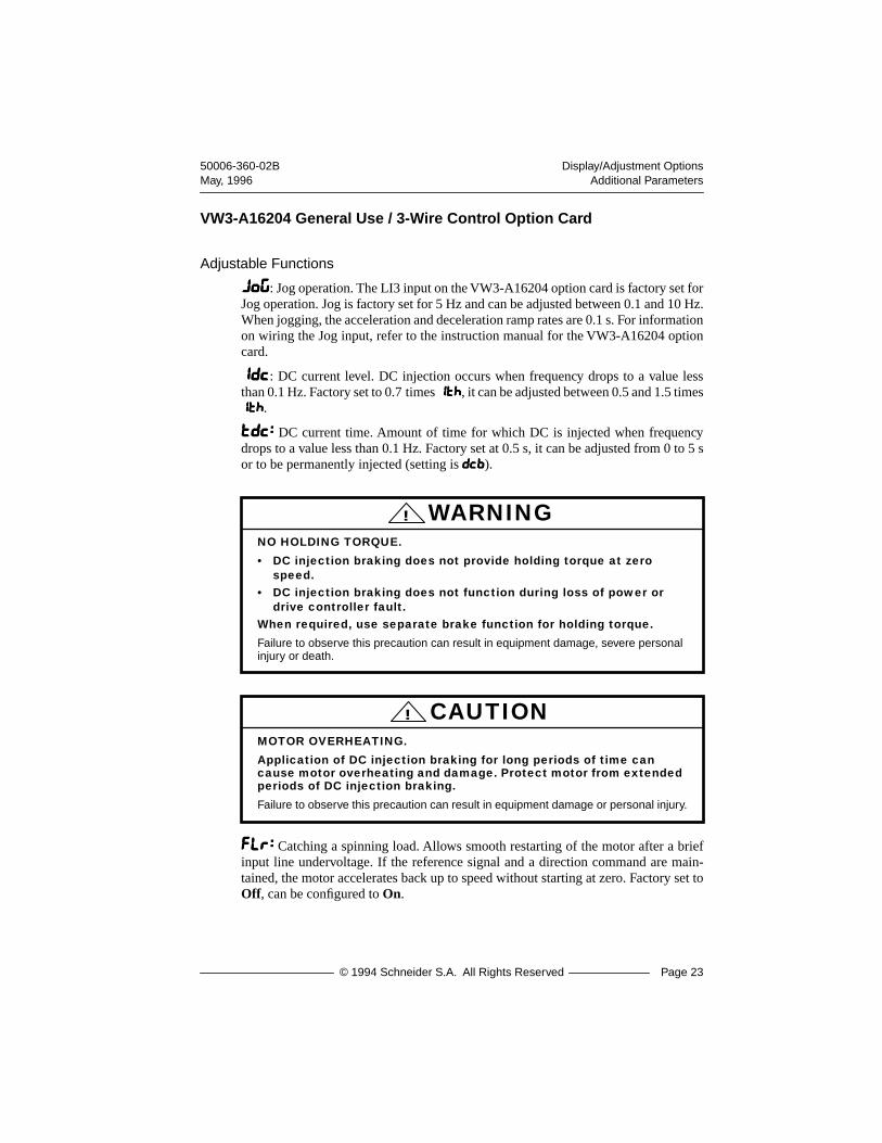
VW3-A16204 General Use / 3-Wire Control Option Card
Adjustable Functions
JJJJooooGGGG: Jog operation. The LI3 input on the VW3-A16204 option card is factory set forJog operation. Jog is factory set for 5 Hz and can be adjusted between 0.1 and 10 Hz.When jogging, the acceleration and deceleration ramp rates are 0.1 s. For informationon wiring the Jog input, refer to the instruction manual for the VW3-A16204 optioncard.
iiiiddddcccc: DC current level. DC injection occurs when frequency drops to a value lessthan 0.1 Hz. Factory set to 0.7 times IIIItttthhhh, it can be adjusted between 0.5 and 1.5 timesIIIItttthhhh.
ttttddddcccc:::: DC current time. Amount of time for which DC is injected when frequencydrops to a value less than 0.1 Hz. Factory set at 0.5 s, it can be adjusted from 0 to 5 sor to be permanently injected (setting is ddddccccbbbb).
FFFFLLLLrrrr:::: Catching a spinning load. Allows smooth restarting of the motor after a briefinput line undervoltage. If the reference signal and a direction command are main-tained, the motor accelerates back up to speed without starting at zero. Factory set toOff, can be configured to On.
NO HOLDING TORQUE.
• DC injection braking does not provide holding torque at zero speed.
• DC injection braking does not function during loss of power or drive controller fault.
When required, use separate brake function for holding torque.
Failure to observe this precaution can result in equipment damage, severe personal injury or death.
! WARNING
MOTOR OVERHEATING.
Application of DC injection braking for long periods of time can cause motor overheating and damage. Protect motor from extended periods of DC injection braking.
Failure to observe this precaution can result in equipment damage or personal injury.
! CAUTION
Display/Adjustment Options 50006-360-02BOperation Assistance May, 1996
Page 24 © 1994 Schneider S.A. All Rights Reserved
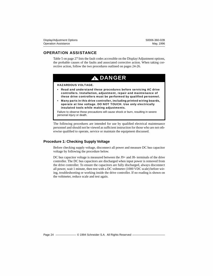
OPERATION ASSISTANCETable 5 on page 27 lists the fault codes accessible on the Display/Adjustment options,the probable causes of the faults and associated corrective action. When taking cor-rective action, follow the two procedures outlined on pages 24-26.
The following procedures are intended for use by qualified electrical maintenancepersonnel and should not be viewed as sufficient instruction for those who are not oth-erwise qualified to operate, service or maintain the equipment discussed.
Procedure 1: Checking Supply Voltage
Before checking supply voltage, disconnect all power and measure DC bus capacitorvoltage by following the procedure below.
DC bus capacitor voltage is measured between the J9+ and J8- terminals of the drivecontroller. The DC bus capacitors are discharged when input power is removed fromthe drive controller. To ensure the capacitors are fully discharged, always disconnectall power, wait 1 minute, then test with a DC voltmeter (1000 VDC scale) before wir-ing, troubleshooting or working inside the drive controller. If no reading is shown onthe voltmeter, reduce scale and test again.
DANGER!
HAZARDOUS VOLTAGE.
• Read and understand these procedures before servicing AC drive controllers. Installation, adjustment, repair and maintenance of these drive controllers must be performed by qualified personnel.
• Many parts in this drive controller, including printed wiring boards, operate at line voltage. DO NOT TOUCH. Use only electrically insulated tools while making adjustments.
Failure to observe these precautions will cause shock or burn, resulting in severe personal injury or death.

50006-360-02B Display/Adjustment OptionsMay, 1996 Operation Assistance
© 1994 Schneider S.A. All Rights Reserved Page 25
The J9+ and J8- terminals are located on the power board, in the general area shownin Figure 17. To measure the bus capacitor voltage, follow the Bus Voltage Measure-ment Procedure below.
Bus Voltage Measurement Procedure
1. Disconnect all power from drive controller.
2. Wait 1 minute to allow the DC bus to discharge.
3. Remove all covers.
4. Set the voltmeter to the 1000 VDC scale. Measure the bus capacitor voltagebetween the J9+ and J8- terminals to verify the DC voltage is less than 45 V.Do not short across capacitor terminals with voltage present!
5. If the bus capacitors are not fully discharged, contact your local Square D rep-resentative – do not operate the drive controller.
6. Replace all covers.
Figure 17 Measuring Bus Capacitor Voltage
DANGER!
HAZARDOUS VOLTAGE.
• Read and understand Bus Voltage Measurement Procedure before performing procedure. Measurement of bus capacitor voltage must be performed by qualified personnel.
• DO NOT short across capacitors or touch unshielded components or terminal strip screw connections with voltage present.
• Many parts in this drive controller, including printed wiring boards, operate at line voltage. DO NOT TOUCH. Use only electrically insulated tools.
Failure to observe these precautions will cause shock or burn, resulting in severe personal injury or death.
J9+ J8- J8- J9+
ATV16U09M2, U18M2ATV16U18N4, U29N4
ATV16U29M2, U41M2ATV16U41N4, U54N4, U72N4

Display/Adjustment Options 50006-360-02BOperation Assistance May, 1996
Page 26 © 1994 Schneider S.A. All Rights Reserved
After measuring DC bus capacitor voltage, check supply voltage by following theprocedure below:
1. Attach meter leads to L1 and L2. Set voltmeter to the 600V AC scale.
2. Reapply power. Voltage should be as follows:ATV16U••M2: 187.2 VAC<V<264 VACATV16U••N4: 340.0 VAC<V<529 VAC
3. Remove power and repeat procedure for L2 and L3, and L1 and L3 if wiredfor three phase.
4. When all phases have been measured, remove power. Remove leads, reinstallcovers.
Procedure 2: Checking the Peripheral Equipment
The following equipment may need to be checked. Follow the manufacturers’ proce-dures when checking this equipment.
1. A protective device such as fuses or circuit breaker may have tripped.
2. A switching device such as a contactor may not be closing at the correct time.
3. Conductors may require repair or replacement.
4. Connection cables to the motor or high resistance connections to ground mayneed to be checked. Follow NEMA standard procedure WC-53.
5. Motor insulation may need to be checked. Follow NEMA standard procedureMG-1. Do not apply high voltage to U, V or W. Do not connect the high po-tential dielectric test equipment or insulation resistance tester to the drive con-troller since the test voltages used may damage the drive controller. Alwaysdisconnect the drive controller from the conductors or motor while perform-ing such tests.
EQUIPMENT DAMAGE HAZARD.
• Do not perform high potential dielectric tests on circuits while the circuits are connected to the drive controller.
• Any circuit requiring high potential dielectric tests must be disconnected from the drive controller prior to performing the test.
! CAUTION
50006-360-02B Display/Adjustment OptionsMay, 1996 Operation Assistance
© 1994 Schneider S.A. All Rights Reserved Page 27
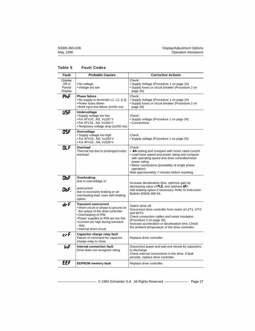
Table 5 Fault Codes
Fault Probable Causes Corrective Actions
Display Off or Partial Display
• No voltage• Voltage too low
Check:• Supply Voltage (Procedure 1 on page 24)• Supply fuses or circuit breaker (Procedure 2 on
page 26)
PPPPhhhhFFFF Phase failure• No supply to terminals L1, L2, (L3)• Power fuses blown• Brief input line failure (t≥200 ms)
Check:• Supply Voltage (Procedure 1 on page 24)• Supply fuses or circuit breaker (Procedure 2 on
page 26)
UUUUSSSSFFFF Undervoltage• Supply voltage too low• For ATV16...M2, V≤187 V• For ATV16...N4, V≤340 V• Temporary voltage drop (t≥200 ms)
Check:• Supply voltage (Procedure 1 on page 24)• Connections
0000SSSSFFFF Overvoltage• Supply voltage too high• For ATV16...M2, V≥264 V• For ATV16...N4, V≥529 V
Check:• Supply voltage (Procedure 1 on page 24)
0000LLLLFFFF Overload Thermal trip due to prolonged motor overload
Check:• IIIIttttHHHH setting and compare with motor rated current• Load base speed and power rating and compare
with operating speed and drive controller/motor power rating
• Motor connections (possibility of single phase operation)
Wait approximately 7 minutes before resetting.
0000bbbbFFFF
0000bbbbFFFF....
Overbraking due to overvoltage or
overcurrent due to excessive braking or an overhauling load, even with braking option.
Increase deceleration time, optimize gain by decreasing value of FFFFLLLLGGGG, and optimize UUUUFFFFrrrr.Add braking option if necessary. Refer to Instruction Bulletin 50006-360-04.
ddddrrrrFFFF Transient overcurrent• Short circuit or phase to ground on the output of the drive controller
• Overheating of IPM•Power supplies to IPM are too low• Current too high during transient
duty• Internal short circuit
Switch drive off. Disconnect drive controller from motor at U/T1, V/T2 and W/T3.Check connection cables and motor insulation (Procedure 2 on page 26).Increase acceleration or deceleration time. Check the ambient temperature of the drive controller.
CCCCrrrrFFFF Capacitor charge relay faultFailure of command for capacitor charge relay to close
Replace drive controller.
IIIInnnnFFFF Internal connection faultDrive does not recognize rating
Disconnect power and wait one minute for capacitors to discharge. Check internal connections in the drive. If fault persists, replace drive controller.
EEEEEEEEFFFF EEPROM memory fault Replace drive controller.
Display/Adjustment Options 50006-360-02BOperation Assistance May, 1996
Page 28 © 1994 Schneider S.A. All Rights Reserved
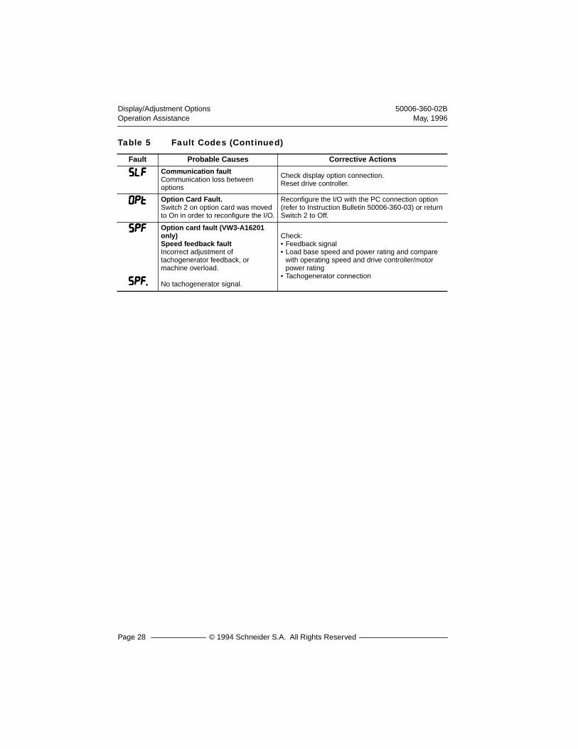
SSSSLLLLFFFF Communication faultCommunication loss between options
Check display option connection.Reset drive controller.
0000pppptttt Option Card Fault.Switch 2 on option card was moved to On in order to reconfigure the I/O.
Reconfigure the I/O with the PC connection option (refer to Instruction Bulletin 50006-360-03) or return Switch 2 to Off.
SSSSPPPPFFFF
SSSSPPPPFFFF....
Option card fault (VW3-A16201 only)Speed feedback faultIncorrect adjustment of tachogenerator feedback, or machine overload.
No tachogenerator signal.
Check:• Feedback signal• Load base speed and power rating and compare
with operating speed and drive controller/motor power rating
• Tachogenerator connection
Table 5 Fault Codes (Continued)
Fault Probable Causes Corrective Actions

50006-360-02B Display/Adjustment OptionsMay, 1996 Operation Assistance
© 1994 Schneider S.A. All Rights Reserved Page 29

Display/Adjustment Options 50006-360-02BOperation Assistance May, 1996
Page 30 © 1994 Schneider S.A. All Rights Reserved

© 1994 Schneider S.A. All Rights Reserved

a
™
16
50006-360-02BDisplay/Adjustment Options May, 1996
© 1994 Schneider S.A. All Rights Reserved
Merlin Gerin Square D Telemecanique
VD
0C01
S30
2
99647