a 20k payload launch vehicle fast track development ... 20k payload launch vehicle fast track...
TRANSCRIPT
NASA Technical Memorandum 108475
....l,./b._"i/ _2
A 20k Payload Launch Vehicle Fast TrackDevelopment Concept Using an RD-180Engine and a Centaur Upper Stage
Compiled byR. Toelle
(NASA-TM-108475) A ZOk PAYLOAD
LAUNCH VEHICLE FAST TRACK OEVELOPMENT CONCEPT USING AN RD-180
ENGINE AND A CENTAUR UPPER STAGE
(NASA. Marshall Space FlightCenter) 80 p
N95-19648
Unclas
0039656
January 1995
https://ntrs.nasa.gov/search.jsp?R=19950013232 2018-05-28T15:37:10+00:00Z

NASA Technical Memorandum 108475
A 20k Payload Launch Vehicle Fast TrackDevelopment Concept Using an RD-180Engine and a Centaur Upper Stage
Compiled byR. Toelle
Marshall Space Flight Center • MSFC, Alabama
National Aeronautics and Space AdministrationMarshall Space Flight Center ° MSFC, Alabama 35812
January 1995

TABLE OF CONTENTS
I. INTRODUCTION ............................................................................................................
A. Objectives ...................................................................................................................
B. Ground Rules/Assumptions ........................................................................................
C. Summary .....................................................................................................................
II. VEHICLE DESCRIPTION ..............................................................................................
A. Vehicle Layout ............................................................................................................B. Aerodynamics .............................................................................................................C. Loads ...........................................................................................................................
D. Performance ................................................................................................................
E. Control ........................................................................................................................
F. Structural Design ........................................................................................................
G. Propulsion Systems .....................................................................................................
H. Avionics Systems ........................................................................................................
I. Mass Properties ...........................................................................................................
J. Main Engine Data .......................................................................................................
III. FABRICATION, INTEGRATION, AND VERIFICATION ...........................................
A. Manufacturing and Assembly .....................................................................................
B. Test Requirements ......................................................................................................
C. Facilities Requirements ..............................................................................................
IV. OPERATIONS REQUIREMENTS ..................................................................................
A. Assembly and Integration ...........................................................................................
B. Flight Operations ........................................................................................................
V. SYSTEM MANAGEMENT .............................................................................................
A. Program Risk Analysis ...............................................................................................
B. System Schedule .........................................................................................................
C. Development Plan .......................................................................................................
D. Data Management .......................................................................................................
VI. FUTURE TRADES ..........................................................................................................
A. Structures Trades ........................................................................................................
B. Stress Trades ...............................................................................................................
C. Aerodynamic Trades ...................................................................................................
D. Propulsion System Trades ..........................................................................................
E. Propulsion Testing Trades ..........................................................................................
F. Performance Trades ....................................................................................................
Page
1
1
3
4
4
418
21
21
3236
43
46
46
54
54
55
56
57
57
57
57
57
59
59
60
63
63
65
65
65
65
66
iii
TABLE OF CONTENTS (Continued)
G. Avionics Trades ..........................................................................................................
H. Design and Manufacturing Trades ..............................................................................
VII. ENVIRONMENTAL REQUIREMENTS ............................................................... .........
A. Environmental Assessment/Environmental Impact Statement ...................................B. Clean Air Act Amendments of 1990 ..........................................................................
C. Clean Water Act--National Pollution Discharge Elimination System
Permit Application ......................................................................................................
D. Deluge Pond Remediation ...........................................................................................E. Asbestos Abatement ...................................................................................................
F. Lead Paint Refurbishment ..........................................................................................
G. Rocket Propellant Handling ........................................................................................H. The Resource Conservation and Recovery Act ..........................................................
VIII. GROWTH PATH OPTIONS ...........................................................................................
IX. CONCLUSIONS AND RECOMMENDATIONS ...........................................................
APPENDIX - Team Members .......................................................................................................
Page
66
66
66
66
66
67
67
67
67
67
68
68
68
7O
iv
LIST OF ILLUSTRATIONS
Figure
1.
2.
3.
4.
5.
6.
7.
8.
9.
10.
11.
12.
13.
14.
15.
16.
17.
18.
19.
20.
21.
22.
Title
Summary of the final configuration .............................................................................
Vehicle configuration ...................................................................................................
Booster separation location ..........................................................................................
Interfaces ......................................................................................................................
RD-180 engine overall dimensions .............................................................................
Aft skirt ........................................................................................................................
20k launch vehicle configuration with fins ..................................................................
Proposed 20k launch vehicle stabilizer fin ..................................................................
Preliminary forebody axial force coefficient (nose configuration comparison) ..........
20k vehicle base drag (preliminary) .............................................................................
Normal force coefficient shape versus Mach number .................................................
Pitching moment coefficient slope versus Mach number ............................................
Center of pressure location ..........................................................................................
20 vehicle pressure distribution (M = 2.0, alpha = 0) ..................................................
Normal force distribution (M = 2.0) ............................................................................
Core vehicle Nx versus alpha .......................................................................................
Shroud load comparison to Titan allowable ................................................................
Shroud shear comparison to Titan allowable ...............................................................
20k in-house vehicle with RD-180 +5-percent thrust overall Nx lineload versus x-station .....................................................................................................
In-house booster design study ......................................................................................
Performance parameters--single RD-170 fixed Centaur upper stage ........................
In-house 20k booster design, flight parameters ...........................................................
Page
3
5
6
7
7
8
9
10
11
12
13
14
15
16
17
18
19
19
20
22
22
24
Figure
23.
24.
25.
26.
27.
28.
29.
30.
31.
32.
33.
34.
35.
36.
37.
38.
39.
40.
41.
42.
43.
44.
45.
LIST OF ILLUSTRATIONS
Title
In-house 20k booster design, flight parameters ...........................................................
20k RD-180 nowinds aero torque to control torque ratio ...........................................
Monthly wind envelope probabilities at 10-km altitude ..............................................
Monthly wind envelope probabilities at 11-km altitude ..............................................
Monthly wind envelope probabilities at 12-km altitude ..............................................
20k RD-180 lox and fuel slosh frequencies ................................................................
20k RD-180 slosh characteristics ................................................................................
Blade stiffeners ............................................................................................................
Feedline/tank interference ............................................................................................
Tank/dry bay interface .................................................................................................
Holddown .....................................................................................................................
Upper stage separation system .....................................................................................
Propulsion system schematic .......................................................................................
Feedline envelope ........................................................................................................
RP fuel tank ullage pressure .........................................................................................
Lox tank ullage pressure ..............................................................................................
20k booster avionics system ........................................................................................
Characteristics ..............................................................................................................
Propellant flow diagram ...............................................................................................
20k initiative isorisk curve ...........................................................................................
20k "fast track" schedule .............................................................................................
Near-term system engineering/activities plan ..............................................................
Near-term system engineering/activities plan ..............................................................
Page
24
25
27
28
29
30
31
32
33
34
34
35
37
38
41
41
43
52
53
59
60
61
62
vi

LIST OF TABLES
Table
1.
2.
3.
4.
5.
6.
7.
8.
9.
10.
Title
Payload exchange ratios ...............................................................................................
Performance results, RD-180 booster and Centaur upper stage ..................................
Propulsion system components ....................................................................................
Propellant inventory .....................................................................................................
RD-180 estimated operating data ................................................................................
Avionics components needed for the 20k booster .......................................................
20k booster weight summary .......................................................................................
In-house 20k launch vehicle mass properties ..............................................................
Initial risk analysis results ............................................................................................
Growth options performance results ............................................................................
Page
23
23
39
42
42
44
46
47
58
69
vii

TECHNICAL MEMORANDUM
A 20K PAYLOAD LAUNCH VEHICLE FAST TRACK DEVELOPMENT CONCEPT
USING AN RD-180 ENGINE AND A CENTAUR UPPER STAGE
I. INTRODUCTION
A concept definition study to define a booster capable of launching a 20k-lb payload from the
Eastern Test Range into a 100-nmi orbit has been performed. Marshall Space Flight Center (MSFC) per-
sonnel from the Science and Engineering and Program Development Directorates were organized into a
high performance work team (the appendix lists the membership). This report captures the results of this3-week effort.
A. Objectives
The objectives of this exercise were to:
Develop a fast-track booster design, manufacturing, and verification program concept based on
using a Commonwealth of Independent States (CIS) RD-180 liquid oxygen/rocket propellant
(LO2/RP) booster engine, an existing upper stage, an existing payload fairing, and be flight ready
in 36 months.
Perform trade studies to select booster size, materials and manufacturing methods, and an upper
stage and payload fairing from existing candidates that will meet the development schedule.
Develop manpower, facilities, tooling and manufacturing, verification, and launch operations
requirements including costs and top level schedules.
B. Ground Rules/Assumptions
The following ground rules and assumptions were developed by the team members and used forthis exercise.
1. Developa launch vehicle concept to compete with the Ariane launch vehicle (performanceand cost)
2. The goal is to design, build, test at MSFC, and deliver to be determined (TBD) flight articlesto the launch site
3. The RD-180 engine is the candidate booster engine, with the RD-170 as backup
4a. The first option is to purchase an existing upper stage, i.e., Centaur/Titan second stage/Delta
upper stage with flight avionics included
4b. The second option is to develop a new upper stage using the following engines (time did not
permit analyzing this concept)
5. UpratedRL-10 seriesarecandidatesasupperstageengines(RL-10C)
6. TheCIS D-57 LO2/LH2engineis anupperstagecandidate
7. Thepayloadrequirementis >20k lb launched due east to low-Earth orbit (LEO), and greater
than 8k lb in geosynchronous transfer orbit (GTO)
7a. LEO = 100 nmi
7b. Total weight (T/W) at lift-off >1.20
8. Payload design margin = 4k lb, no stage weight design margin ,at this time
9a. The baseline is to purchase payload fairing
9b. The second option is to develop a user-friendly/cost-effective payload fairing
10. Design the structural margin so that vehicle is not performance limited to preclude potential
flight restrictions, i.e.:
• Set structural design safety factor = 2 to eliminate testing• Trade cost of lowering to 1.4
• Show delta cost/processes/tolerances, etc. due to extra weight resulting from high safetyfactor
11. Define process of "0-Base" specifications and build to only what is necessary
12. Set up very tight controls of design reviews (DR's) and limit to what is necessary
13. Streamline interface documents and requirements
14. Develop manufacturing process for inexpensive production, i.e., new technology of spin
forming, hydroshock forming, extruding and forging, and statistical process controlled (SPC) welding
15. Set up verification criteria at assembly plant that delivers ready-to-fly hardware to launch site
16. Develop booster avionics using as much commercial-grade components and procedures as
possible to meet required reliability
17. Booster avionics has automatic self testing
18. Standardize mission profiles
19. Develop flight software to accommodate a spectrum of payload weights and center-of-gravity
locations to reduce preflight analyses
20. The payload is required to be processed off-line and delivered to launch vehicle ready to fly,
except for structural and electrical attachment to vehicle
21. Design for minimum time on launch pad, i.e., goal of 1 day after hard down
2
22. Automategenerationof inducedenvironmentdatato payload,i.e., loads,acoustics,tempera-ture,shocks,etc.
23. Automatepostflight analysisto maximizecomputerlookingfor anomalies
24. Stopengineeringdevelopmentafterfive flights.
25. Investigategrowthscenarioto 65k to LEO;65k includesupperstageto movepayloadstootherorbits.
C. Summary
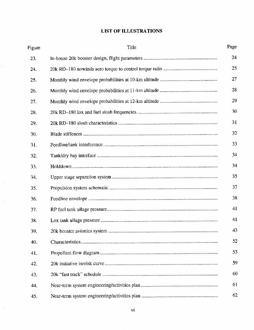
Figure 1 displays a summary of the final configuration. It consists of a booster constructed of
2219 aluminum-welded tank dome gores and barrel panels and one two-nozzle RD-180 engine. A struc-
tural design safety factor of 2 was used to reduce the structural test program and to meet the schedule. A
5-percent thrust increase of the RD-180 engine is required to meet the payload with margin. The
manufacturer's representative said that this is attainable. The upper stage is a Titan IV Centaur withRL-10 A4 engines, which are required to meet the payload margin. The payload fairing is a McDonnell
Douglas Titan IV, modified to meet attachment requirements. The estimated development schedule is 40
months versus the goal of 36 months. The vehicle design, development, test, and evaluate (DDT&E)estimates are between $480 and $550M in 1993 dollars, excluding the launch complex modifications.
Recurring costs are estimated at $78 to $85M per flight.
20K LV CONCEPT
Notes:
Side View Base View
• 90 ° Launch Azimuth• MECO @ 100 nmi. circ.• T/W @ Liftoff = 1.20
• Max G =4.50/Max q = 600 psf
Payload: 20.7 k Ib ]Final Position: 100x 100 nmi @ 28.5 °GLOW: 731 klb
Payload Falrlna
Jettisoned Mass 9,200 Ib
Inert Mass: 8.0 klbPropellant Mass: 44.6 klb
Propellant Type: LOX/LH2Engine Type/# Ea.: RLIOA-4¢2Vac Thrust (Ea): 20.8 klbVac ISP: 448.9 s
Stage Diameter: 14.7 ffStage Length: 29.5 tt
First Steoe Booster
Inert Mass: 55.7klb
Propellant Mass: 588 klbPropellant Type: LOX/RPEngine Type/#: RD180/1Vac/SL Thrust (Ea): 945/872 klbVao/SL ISP: 3371309 sStage Length: 83 ftStage Diameter: 16.7 ffStructure Material: A12219
Figure 1. Summary of the final configuration.
3

H. VEHICLE DESCRIPTION
A. Vehicle Layout
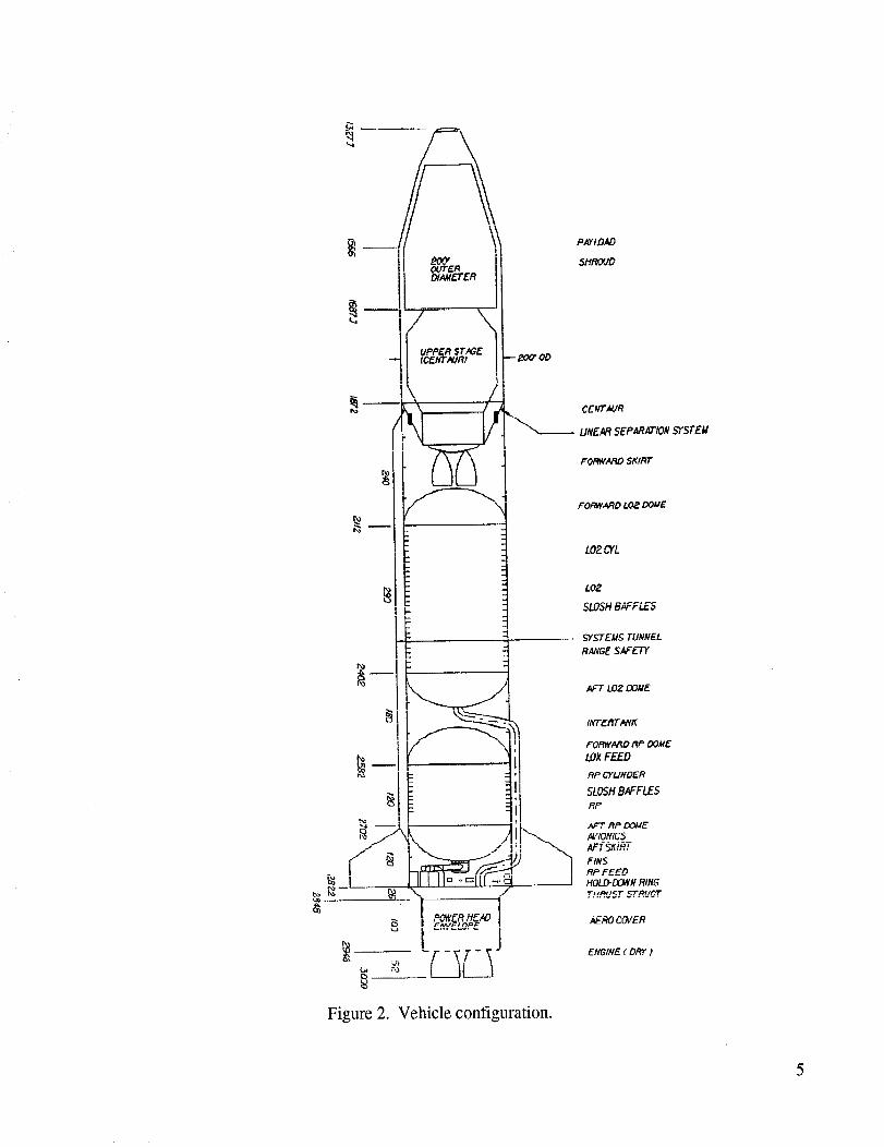
The resulting configuration is shown in figure 2. The vehicle has a Titan IV-size payload shroud
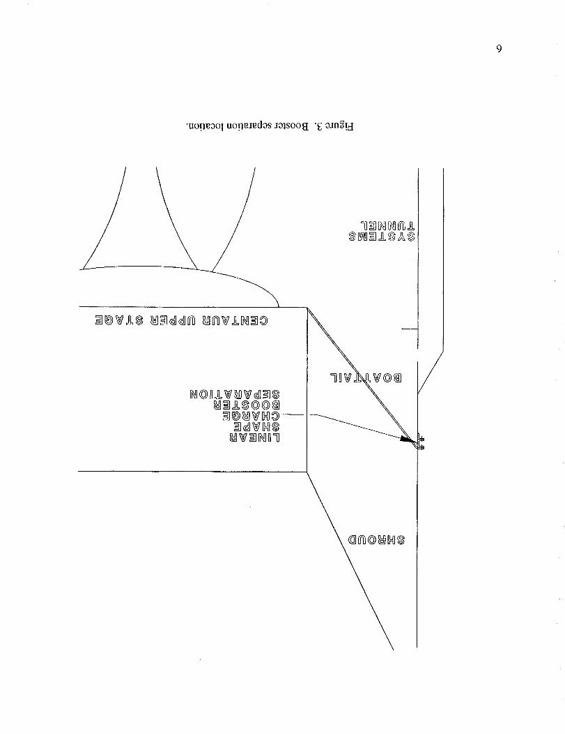
(200-in diameter) enclosing a Centaur (168-in diameter) upper stage and payload. The booster is jetti-soned before the shroud, therefore, the linear-shaped charge-stage separation system is located just
below the booster/shroud interface (fig. 3). The shroud is attached to the upper stage through a boattail
that is loaded in tension during the boost phase. Ullage motors to separate the stages and settle the
Centaur propellants are mounted on the boattail. Payload contamination during booster separation is not
an issue since the payload will still be shrouded.
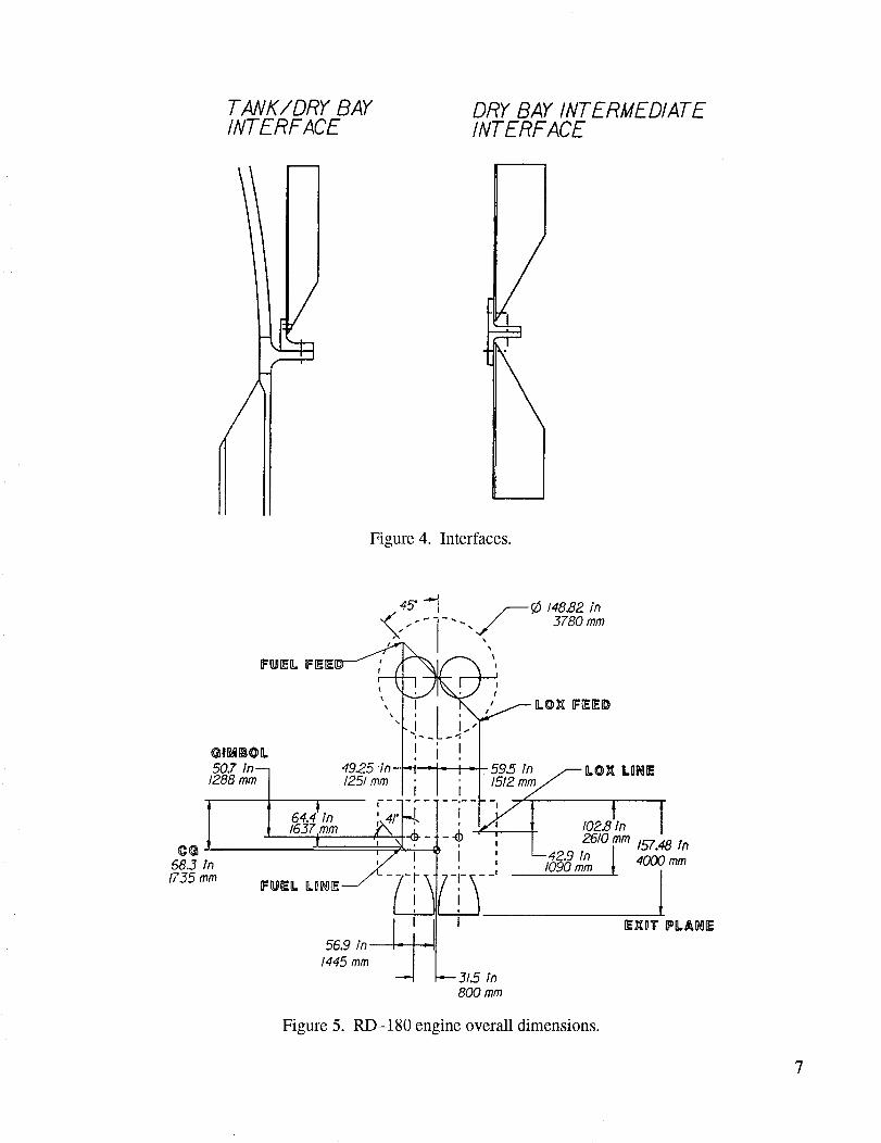
The booster dry bays (the interstage or forward skirt, the intertank, and the aft skirt) are made ofidentical elements assembled to provide the required lengths. Interfaces are rings riveted onto the cylinder
with an external bolt flange (fig. 4). Certain dry bay panels will need reworking to allow penetrations and
access doors. All booster avionics (except the rate gyro, range safety, and antennae) are mounted in the aft
skirt.
The booster LO2 tank is located forward and has a continual cross section along its length. Due
to material blank size availability, there will have to be a circumferential weld in the middle, but the twohalves will be the same. The tank domes are sized so that the weld strength is sufficient to carry the load.
This means that there is no need for machining weld lands onto the gores. Three of the domes, the for-
ward LO2 dome and both RP domes, are of identical thickness. Only the aft LO2 tank dome is a different
thickness.
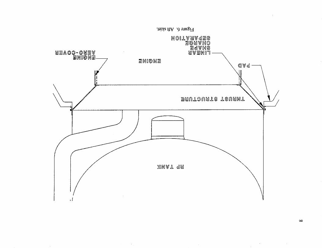
The RD-180 engine system (fig. 5 and section II.J) is supported by a series of struts onto a circu-
lar pattern. The struts interface with a small conical thrust structure which carries the loads into the aftskirt (fig. 6). The engine is surrounded by a close-fitting shell to protect it from aerodynamic loads. This
aerodynamic shell would also be used to support the engine supplied base heat shield.
The vehicle to pad holddown is at the base of the aft skirt, above the engine. It consists of a cir-cumferential linear-shaped charge. This design reduces the point loads between the launch pad and
vehicle, resulting in a more efficient structure.
B. Aerodynamics
Preliminary aerodynamics were determined for the 20k launch vehicle configuration as shown in
figure 7. These initial estimates were based on wind tunnel test data of the Titan IV payload fairing andthe core stage of an in-line shuttle-derived launch vehicle with similar dimensions. The data were used
to determine payload performance, structural loads, and control system requirements for the vehicle.
Early study analysis indicated inadequate control authority at maximum dynamic pressure,
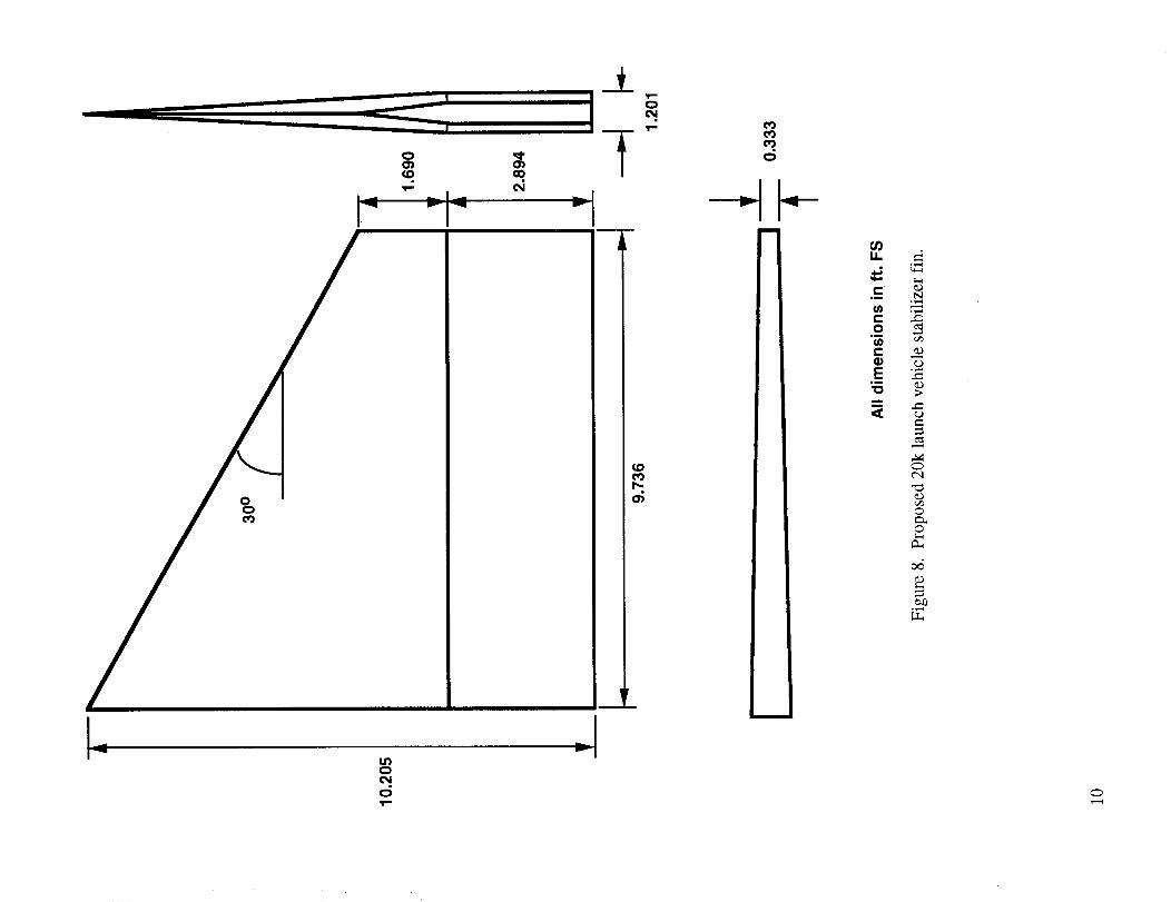
primarily due to the mass properties of the LO2/RP tankage. As a possible solution, the stabilizer fin
configuration shown in figure 8 was proposed to correct the problem aerodynamically. The planformand airfoil section were derived from the Saturn V lunar orbit rendezvous (LOR) fin configuration,
which was modified to accommodate the cylindrical body and sized to meet the control requirements.
4
PAYLOAD
5ttROVD
uPPER ST
CCE:NTAURP/- I --_OD
CEICTNJR
UNEAR 5EPN_ATION SYSTEM
FORWARDSKIRT
FORWARD LOP..OO/,I/E
LO_ CYL
I 1- -I SLOSH BAFFLES
RANGE SAFETY
I _ INTERT_K
/ _:'1 FORWARORPDOWELOXFEED
SLOSHBAFFLES
FINSRP FEED
t. III I1':'"'= J HOgaN RINGTH._,J3T STRUGT
! .....ot _fRO 6_ER
_-' [ 3L_]N
AFT LOZDONE
Figure 2. Vehicle configuration.
9
•uo!l_oI uo!l_x_d_s Jalsoot "EoJn_'!_
lOIli?I?_lillllilllg@@ll
II@IIVIII@ --
II?IIII
%iiiiii RIIilIL
]IV I?QI
TANK�DRY BAYINTERFACE
/
DRY BAY INTERMEDIATEINTERFACE
Figure 4. Interfaces.
Figure 5. RD-180 engine overall dimensions.
7
•l.r_s UV "9 zan_!_I
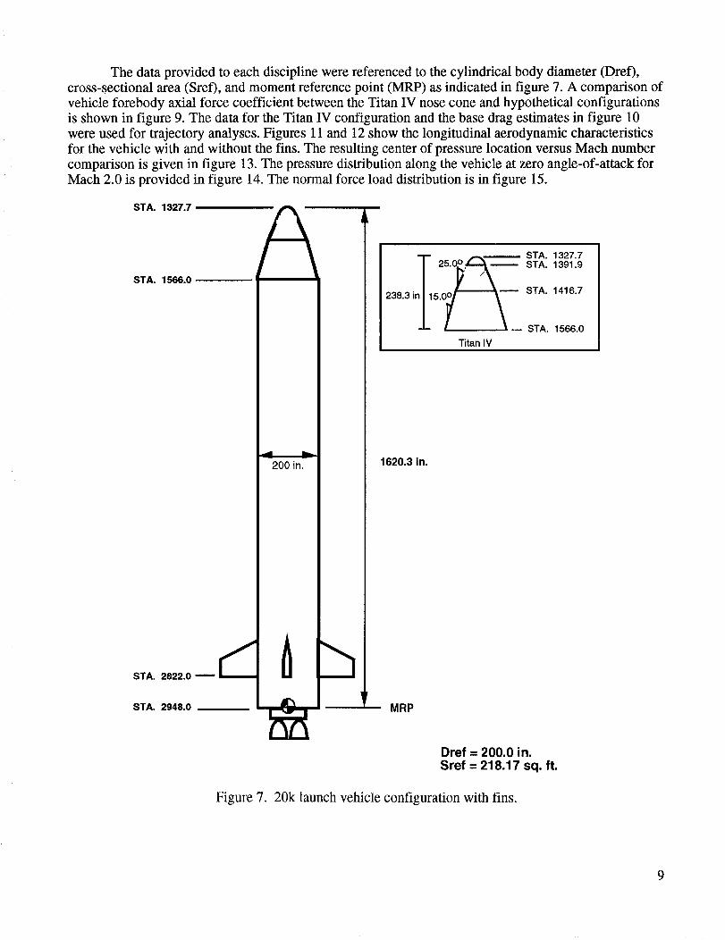
The data provided to each discipline were referenced to the cylindrical body diameter (Dref),cross-sectional area (Sref), and moment reference point (MRP) as indicated in figure 7. A comparison of
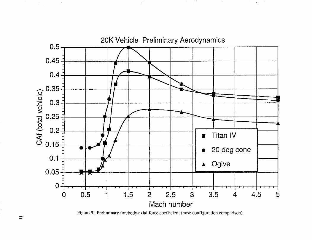
vehicle forebody axial force coefficient between the Titan IV nose cone and hypothetical configurations
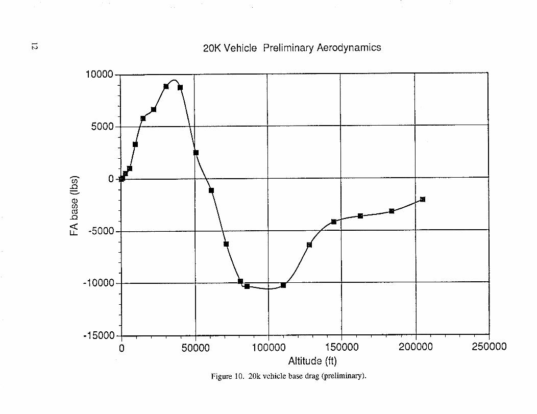
is shown in figure 9. The data for the Titan IV configuration and the base drag estimates in figure 10
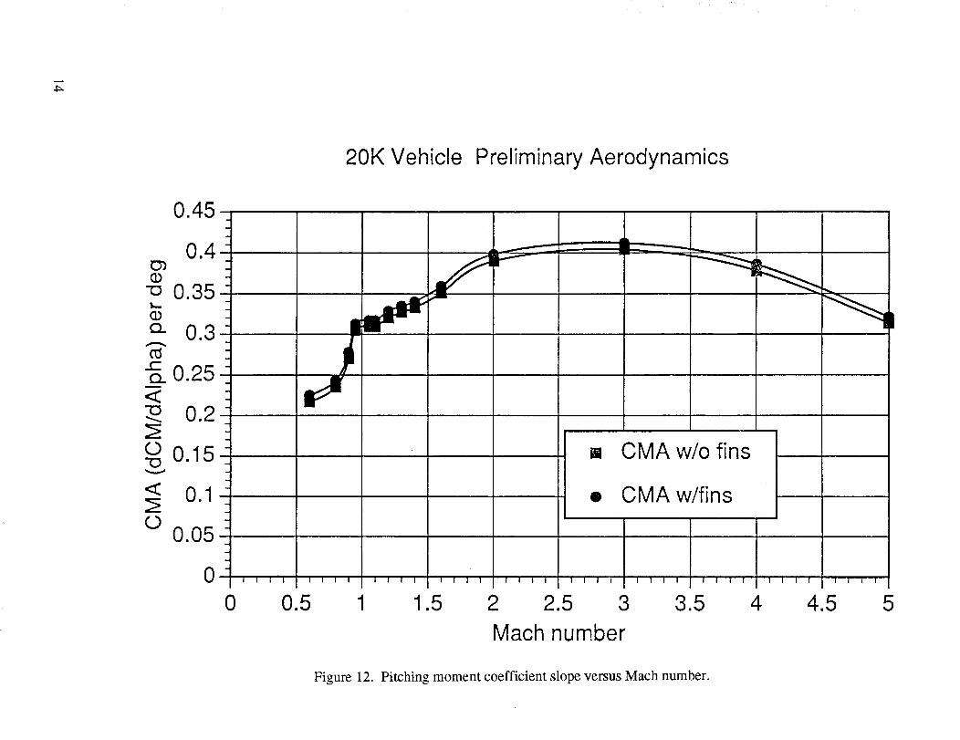
were used for trajectory analyses. Figures 11 and 12 show the longitudinal aerodynamic characteristics
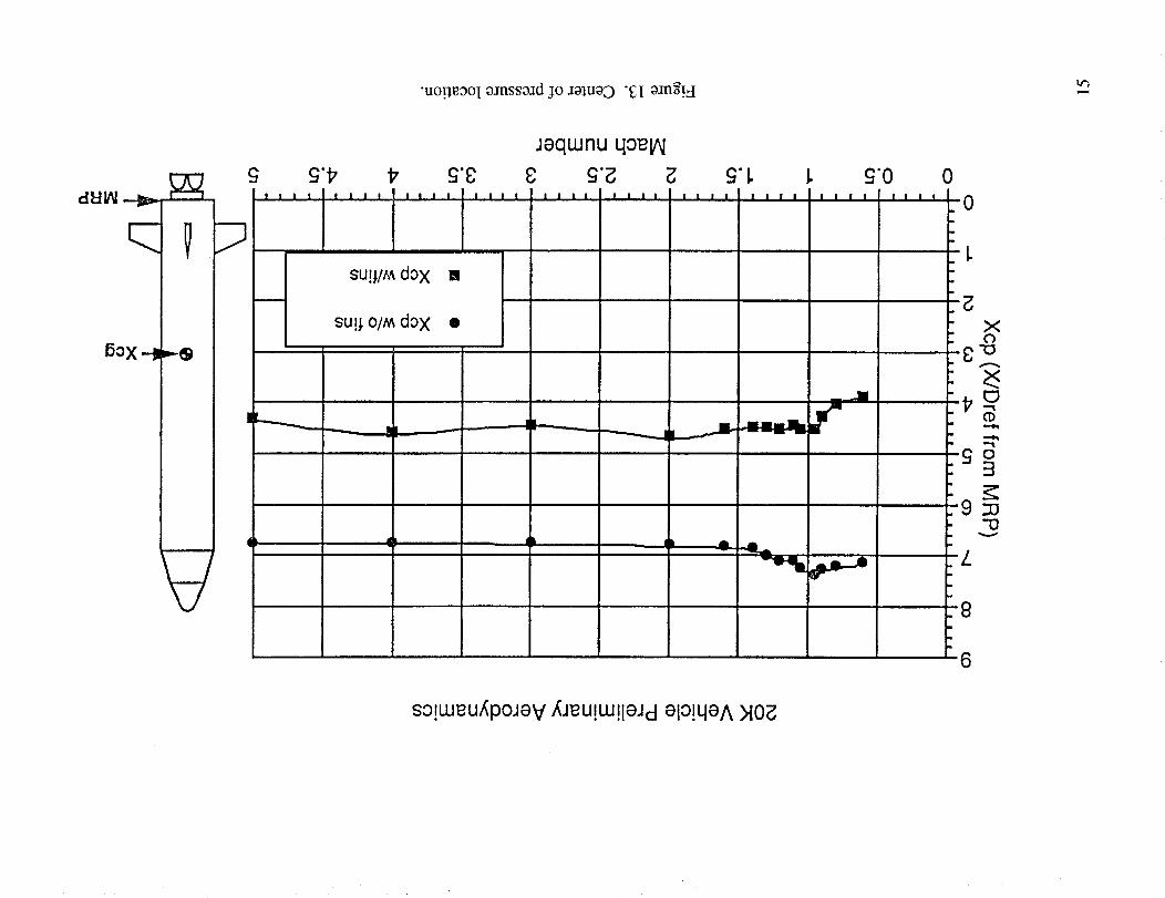
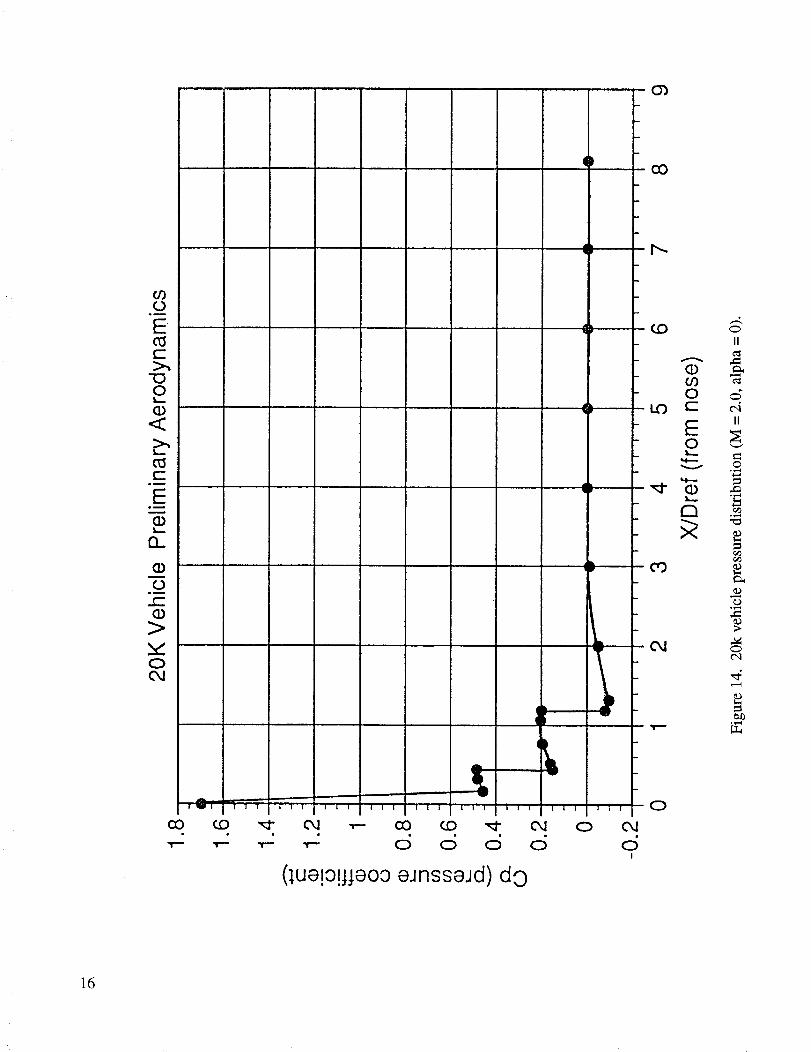
for the vehicle with and without the fins. The resulting center of pressure location versus Mach number
comparison is given in figure 13. The pressure distribution along the vehicle at zero angle-of-attack for
Mach 2.0 is provided in figure 14. The normal force load distribution is in figure 15.
STA. 1327.7
STA. 1566.0
200 in.
STA. 2822.0
STA. 2948.0
T _.-_, STA. 1327.7
25. STA. 1391.9
238.3 In115 0_ _ STA. 1416.7m STA. 1566.0
Titan IV
1620.3 in.
MRP
Dref = 200.0 in.Sref = 218.17 sq. ft.
Figure 7. 20k launch vehicle configuration with fins.
9
0
_0c_
o_
c_jc_
•91m
LL _
C .c_
C _
E _
cJ_0
0
0.45
_. 0.35
<o 0.15
0.05
0
20K Vehicle Preliminary Aerodynamics
[] Titan IV
• 20 deg cone
0 0.5
Figure 9.
1 1.5 2 2.5 3 3.5 4
Mach numberPreliminary forebody axial force coefficient (nose configuration comparison).
4.5 5
to 20K Vehicle Preliminary Aerodynamics
03
mv
(D03
<I.L.
10000
50O0 t
0 -!_
-5000-
-10000
-15OOOI I t I I I I I
0 50000I l I I
100000
J
I I I I I I I I
150000 200000 250000
Altitude (ft)
Figure 10. 20k vehicle base drag (preliminary).
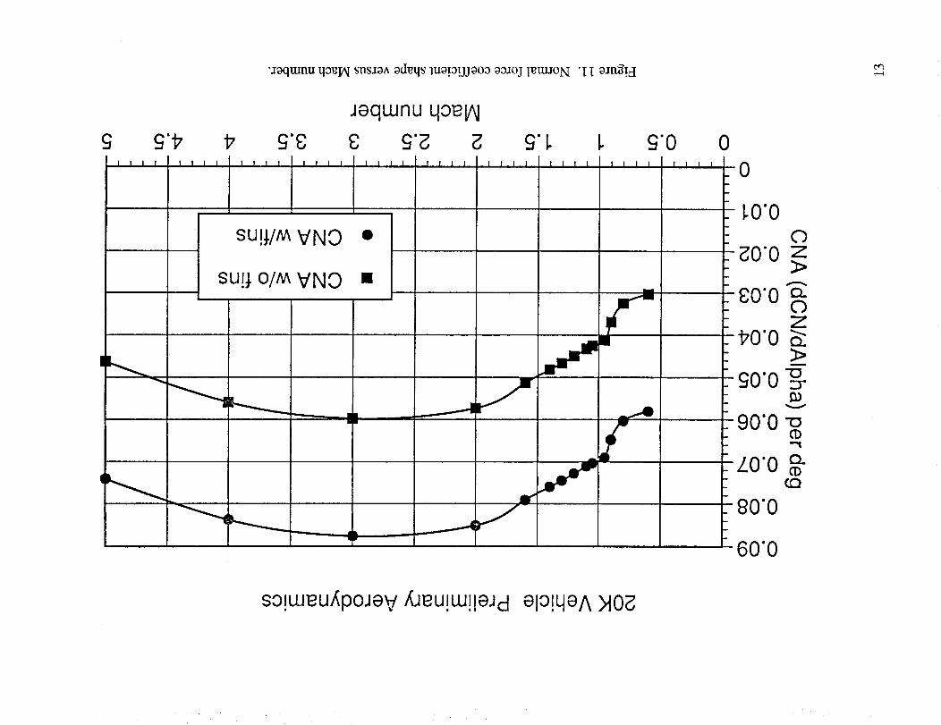
•JoqtunuqoelAIsnSJOAodgqsluo!o!JJOOOoo:_ojIettuoN "I I oang!_I
Jeqwnu 4oelA!
I111 t11t 1111
su!;/M
su!l o/M
IIII
VNO
VNO
IIL,1,,,
0
[]
,1111 II1,,1 IIII IIII IIII
Iiiiiiiii
-0
_0"00
_0"0 z3>
gO'O "_170'0 S"
>
-£0"0 -o:3"
V
-90"0 -o"i
LO'O o_f.Q
90"0
60"0
so!weu,_poJev XJeu!w!!aJcl eio!qeA _lOg
4:_
20K Vehicle Preliminary Aerodynamics
0.45
0.4O3(1)'o 0.35
o.. 0.3
0.250.2
O 0.15"O
< 0.1
00.05
0 I I I
0
=
IIII t111 llll IlJl IIIl
L
[] CMA w/o fins
• CMA w/fins
tlii IIII It1[
0.5 1 1.5 2 2.5 3 3.5 z 5
Mach number
Figure 12. Pitching moment coefficient slope versus Mach number.
"uo!leooIo_nssoadjo 3oluoD"_I oang!H
dkli_l _
60X -
I
w
I
IIII
II
£'17 17 £'8! I I I ! ! I I ! ! ! I I ! ! I
|
JequJnu qoelAl
I I I I
£'1.I I ! ! IIII !111
LI ! I t
--II
Ih II
£'0 0I I I I -0
XC)
I0_)
0"£ ::!
E9;u
-I3
-Z
-8
6
so!weu/_poJev/[Jeu!w!leJdelo!qeAMO_
q
0_0
(1)09"0
0o
n
oc-oD
ooN!
Ah• CO
04
oII
e4II
o
S
c_
ocq
(;ue!0!jja0o eJnssaJd) do
0
O4c5
16

"(0"E = IAI) uo.rlnq.ms!p oo_oj rettUON "g[ oJng!_I
6! I I I IIIL
I
IIII,
I
(esou LLIOJjt) _eJG/X
£ #IIII IIII
UU
I 1 I ! ! i I I
8 Z 9! I I I
I
£'0
0Z
V
m.
so!weu/_poJev_eu!w!leJd elo!qeA>I0_
(a)differences.
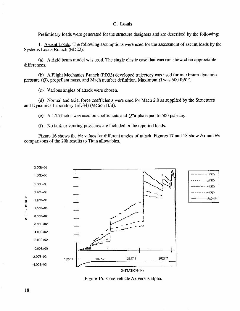
C. Loads
Preliminary loads were generated for the structure designers and are described by the following:
1. As¢¢nt Loads. The following assumptions were used for the assessment of ascent loads by the
Systems Loads Branch (ED22):
A rigid beam model was used. The single elastic case that was run showed no appreciable
(b) A Flight Mechanics Branch (PD33) developed trajectory was used for maximum dynamic
pressure (Q), propellant mass, and Mach number definition. Maximum Q was 600 lb/ft 2.
(c) Various angles of attack were chosen.
(d) Normal and axial force coefficients were used for Mach 2.0 as supplied by the Structures
and Dynamics Laboratory (ED34) (section II.B).
(e) A 1.25 factor was used on coefficients and Q'alpha equal to 500 psf-deg.
(f) No tank or venting pressures are included in the reported loads.
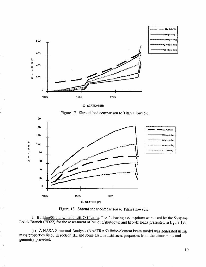
Figure 16 shows the Nx values for different angles-of-attack. Figures 17 and 18 show Nx and Nv
comparisons of the 20k results to Titan allowables.
2.00E+03
1.80E+03
1.60E+03
1.40E+03
1.20E+03
1.00E+03
8.00E+02
6.00E+02
4.00E+02
2.00E+02
0.00E+00
-2.00E+02
-4.00E+02
m
1327.7 - - 1827.7 2327.7
"'-----_ "1
2827.7
X-STATION (IN)
Figure 16. Core vehicle Nx versus alpha.
I DEG
........ 2DEG
4DEG
....... 6DEG
RADIUS
18
800
600
4O0
200
0
1325 1525 1725
m_==,= _ NX ALLOW
600 psf-deg
-- 1200 psf-deg
.............. 2400 psf-deg
_3600 psf-deg
X- STATION (IN)
Figure 17.
160
Shroud load comparison to Titan allowable.
140
120
100 ,_-.
80
60
40
20
o I I
='=_='= _ Nv ALLOW
'3600 psf-deg
'2400 psf-deg
1200 psf-deg
'600 psf-deg
1325 1525 1725
X - STATION (IN)
Figure 18. Shroud shear comparison to Titan allowable.
2. Buildup/Shutdown and Lift-Off Loads. The following assumptions were used by the Systems
Loads Branch (ED22) for the assessment of buildup/shutdown and lift-off loads presented in figure 19:
(a) A NASA Structural Analysis (NASTRAN) finite-element beam model was generated usingmass properties listed in section II.I and some assumed stiffness properties from the dimensions and
geometry provided.
19
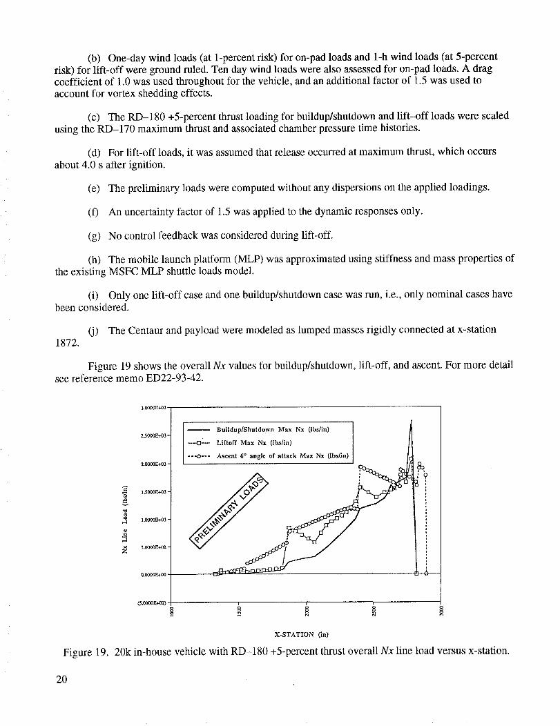
(b) One-daywind loads(at 1-percentrisk) for on-padloadsand1-hwind loads(at 5-percentrisk) for lift-off weregroundruled.Tendaywind loadswerealsoassessedfor on-padloads.A dragcoefficientof 1.0wasusedthroughoutfor thevehicle,andanadditionalfactor of 1.5wasusedtoaccountfor vortexsheddingeffects.
(c) TheRD-180 +5-percentthrustloadingfor buildup/shutdownandlift-off loadswerescaledusingtheRD-170 maximumthrustandassociatedchamberpressuretimehistories.
(d) Forlift-off loads,it wasassumedthatreleaseoccurredatmaximumthrust,which occursabout4.0s afterignition.
(e) Thepreliminaryloadswerecomputedwithout anydispersionsontheappliedloadings.
(f) An uncertaintyfactorof 1.5wasappliedto thedynamicresponsesonly.
(g) Nocontrolfeedbackwasconsideredduringlift-off.
(h) Themobilelaunchplatform(MLP) wasapproximatedusingstiffnessandmasspropertiesoftheexistingMSFCMLP shuttleloadsmodel.
(i) Only onelift-off caseandonebuildup/shutdowncasewasrun, i.e.,only nominalcaseshavebeenconsidered.
(j) TheCentaurandpayloadweremodeledaslumpedmassesrigidly connectedatx-station1872.
Figure 19showstheoverallNx values for buildup/shutdown, lift-off, and ascent. For more detailsee reference memo ED22-93-42.
Figure 19.
3.000_E+03 -
2.5000E+03 -Buildup/Shutdown Max Nx (lbs/in)
Liftoff Max Nx (Ibs/in)
Ascent 6* angle of attack Max Nx (lbshn)
X-STATION (in)
20k in-house vehicle with RD-180 +5-percent thrust overall Nx line load versus x-station.
20

D. Performance
Initial parametric performance data were generated using the ground-ruled RD-180 as the
booster engine with existing upper stage(s) and payload fairing. Booster sizing was performed using
booster weight scaling equations with the Titan IV Centaur or Titan IV stage II upper stages. An Atlas-
type payload fairing was jettisoned during ascent at 400,000 ft. Figure 20 displays the resulting payloadof each upper stage combination in conjunction with a sized booster. The Titan IV stage II was rejectedbased on these data.
Figure 21 displays payload and Max q parameters versus booster vacuum thrust. The data show
that increasing booster thrust alone, with corresponding propellant increase, could meet the payload
requirement, but a limit of 5-percent increase was set by the engine team (see section ll.J). Therefore,
the remaining payload deficit had to be made up by the upper stage. RL10A-4 engines were substituted
for the standard RL10-3-3A Centaur engines and combined with the 5-percent booster thrust increase,
and the payload was achieved.
Table 1 displays the payload exchange ratios generated and delivered to the design teams fordetailed analyses.
As the design was iterated, a decision was made to enclose the upper stage within the payload
fairing to minimize the structural modifications required to handle the airloads. The Titan IV 200-in
diameter fairing was introduced into the analyses and baselined. This increased fairing weight caused a
payload reduction, but the 20k lb requirement was still attainable.
Following structural design, control, and aerodynamic trades, the final configuration evolved and
is summarized in table 2. Performance for both LEO and GTO missions are provided. Detailed trajectory
data were generated, delivered to the design teams, and are available upon request from the Flight
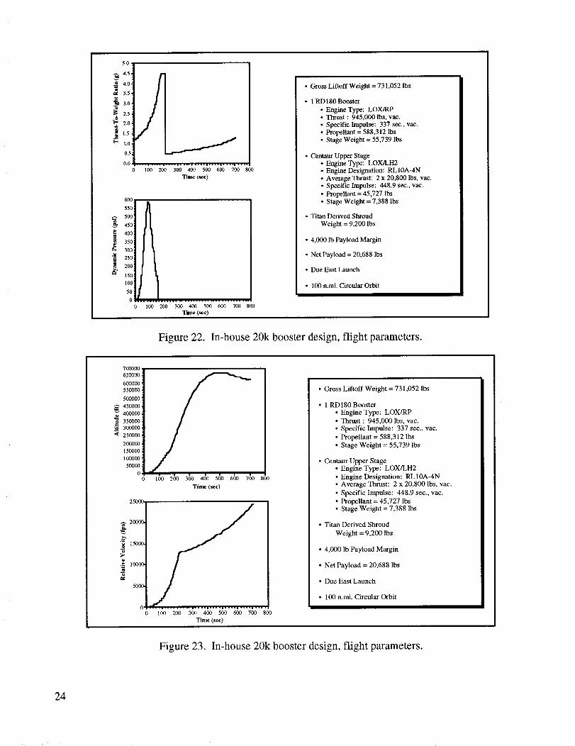
Mechanics Branch (PD33). The resulting flight parameters are displayed in figures 22 and 23.
E. Control
1. Overview. Analyses conducted to evaluate the ascent controllability characteristics of this 20k
launch vehicle concept are presented. Static stability and rigid-body dynamic response envelopes and apreliminary analysis of slosh damping requirements are discussed.
2. Configuration. Control of the 20k launch vehicle is by independently gimbaling the twoRD-180 nozzles about two axes. These nozzles move in concert to provide pitch and yaw control
torques, and move differentially to provide roll control torque. The RD-180 includes integrated thrust
vector control (TVC) actuators with a capability of providing +8 ° gimbal angle and +3°/s gimbal angle
rate under working load. Thus, the suitability of this capability for the 20k launch vehicle will be anissue.
3. Controllability.
a. Static Stability. A first measure of a launch vehicle's controllability characteristics is the
ratio of the maximum available control torque to the maximum disturbance torque, Cr. A rule of thumb
for vehicle concepts at an early design stage is to keep this ratio greater than 2. This will provide ade-
quate margin for configuration maturity and dispersions and will account for the unmodeled effects.
Early 20k launch vehicle concepts of this exercise were evaluated and found to be unacceptable due to
21
20000.,
,i
18000.]
16000"_- ............. .......
14000 "_....................................
12ooo__ -_. 10000-_
Z 8000 "_
60(I0 ,_
4000 -_
2000 ._
ol
In-House Booster Design Study
i i i
• Centaur Upper Stage ]
ITitan IV STG 2
i
::• • , , l • i • • I a • • i i | • • | i | • • • l • • , • i
5 10 15 20 25 30
Launch Latitude, deg.
Ground Rules and Assumptions
• 4,000 lb Payload Margin
• 4.5 g-limit• 1 RD180 LOX/RP Booster
• Atlas Derived Shroud
• Due East Launch
• 100 nmi circular oribt
* Upper Stages from AIAA International
Reference to Space Launch Systems
• T/W at liftoff = 1.2
Figure 20. In-house booster design study.
Performance Parameters - Single RD170
Fixed Centaur Upper Stage
50000 - -900
45000.
40000,
35000.
_30000.
25000-
Z 20000,
15000.
10000,
5000.
Ground Rules and Assumptions Payload for ,880
• 4.000 lb Payload Margin Up-graded Centaur Thrust and Isp• 4.5 g-limit• 1 RDI70 LOX/RP Booster .860
• Atlas Derived Shroud
Due East Launch _i
100 nmi circular oribt _ !
Upper Stages from AIAA International _ i i
Reference to Space Launch Systems /_--'i ............
• T/W at lifloff= 1.2 ....... ".'.'...... "......... ......
J Dynamic Pressure for !
Payloadray,oa_,,__i and. is p
inlc P '740y ' i .......
'720
0 700800............................. 4'0..................900 1000 1100 1200 1300 1 0 1500 1600 1700 800
Initial Vacuum Thrust (klbs)
,840
g'820
,800 ._
,780 _
,760
Figure 21. Perfommnce parameters--single RD-170 fixed Centaur upper stage.
22

Table 1. Payloadexchangeratios.
Partials 5-PercentThrustIncrease
BoosterDrop Weight
AerodynamicDrag
ShroudDropWeight
-0.266lb payload/lbdropweight
-8.60 lb payload/percentchange
-0.305 lb payload/lbdropweight
Table2. Performanceresults,RD-180boosterandCentaurupperstage.
Weights
Gross Lift-Off Weight
B ooster
Propellant
Stage Weight
Upper Stage
Propellant
Stage Weight
Shroud Weight
Margin
Net Payload
Flight Parameters
Maximum Dynamic PressureMinimum RD-180 Throttle
Maximum Acceleration
Total Weight at Lift-Off
Engine DataRD-180
Thrust, Vacuum
Isp, Vacuum
RD-10A-4 (2)Thrust, Total Vacuum
Isp, Vacuum
LEO GTO
731,052 lb
588,312 lb
55,739 lb
45,727 lb
7,387 lb
9,200 lb
4,000 lb
20,688 lb
591 lb/ft 2
715,112 lb
588,312 lb
55,739 lb
45,727 lb
7,387 lb
9,200 lb795 lb
7,953 lb
623 lb/ft 2
67.97 percent
4.5g1.193
945,000 lb/ft337 s
41,600 lb/ft448.9 s
60.38 percent
4.5g1.219
945,000 lb/ft337 s
41,600 lb/ft448.9 s
23
5.0,
4.5,
._ 4.0,
3.5,
3.o,
,_ 2.5,,_, 2.0,
•_ 1.5,
1.0,
0.5,
0.0
600
55O
500
_- 450
400
350
300
"_ 250
200
150
100
50
0
1
,r#
/
.... , .... ° .... • .... , .... , .... , .... , ....
100 200 500 400 500 600 700 800
Time (set)
100 200 300 400 500 600 700 800
Time (see)
• Gross Liftoff Weight = 731,052 lbs
• 1 RD180 Booster
• Engine Type: LOX/RP• Thrust : 945,000 lbs, vae.
• Specific Impulse: 337 sec., vac.• Propellant = 588,312 lbs• Stage Weight = 55,739 lbs
• Centaur Upper Stage• Engine Type: LOX/LH2• Engine Designation: RL 10A-4N• Average Thrust: 2 x 20,800 lbs, vac.• Specific Impulse: 448.9 see., vac.
• Propellant = 45,727 lbs• Stage Weight = 7,388 lbs
• Titan Derived Shroud
Weight = 9,200 lbs
• 4,000 lb Payload Margin
• Net Payload = 20,688 lbs
• Due East Launch
• 100 n.mi. Circular Orbit
Figure 22. In-house 20k booster design, flight parameters.
700000
650000
600000
550000
500000
450000
_ 40(1000350000
300000
250000
200000
150000 i
100000 _
25O00.
,_ 2OOOO.
150O0.
Y.._" 10060,
50013
0
• • • , • i •100 200 300 400 500 600 700 800
Time (see)
.... • .... , .... i .... • .... , .... • .... • ....
100 200 30_1 400 500 600 7130 800
Time (see)
• Gross Liftoff Weight = 731,052 lbs
• 1 RD180 Booster
• Engine Type: LOX/RP
• Thrust : 945,000 lbs, vac.• Specific Impulse: 337 sec., vac.
• Propellant = 588,312 lbs
• Stage Weight = 55,739 lbs
• Centaur Upper Stage• Engine Type: LOX/LH2
• Engine Designation: RL10A-4N• Average Thrust: 2 x 20,800 lbs, vac.
• Specific Impulse: 448.9 sec., vac.• Propellant = 45,727 lbs• Stage Weight = 7,388 lbs
• Titan Derived Shroud
Weight = 9,200 lbs
• 4,000 lb Payload Margin
• Net Payload = 20,688 lbs
• Due East Launch
• 100 n.mi. Circular Orbit
Figure 23. In-house 20k booster design, flight parameters.
24
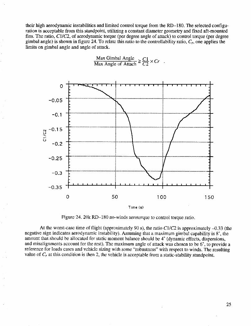
their high aerodynamic instabilities and limited control torque from the RD-180. The selected configu-
ration is acceptable from this standpoint, utilizing a constant diameter geometry and fixed aft-mounted
fins. The ratio, CllC2, of aerodynamic torque (per degree angle of attack) to control torque (per degree
gimbal angle) is shown in figure 24. To relate this ratio to the controllability ratio, Cr, one applies the
limits on gimbal angle and angle of attack.
Max Gimbal Angle > C 1Max Angle of Attach - C2 x Cr
0
-0.05
-0.1
-0.I 5(J
(J
-0.2
-0.25
-0.3
-0.35
0 50 100 150
Time (s)
Figure 24. 20k RD-180 no-winds aerotorque to control torque ratio.
At the worst-case time of flight (approximately 90 s), the ratio C1/C2 is approximately -0.33 (the
negative sign indicates aerodynamic instability). Assuming that a maximum gimbal capability is 8 °, the
amount that should be allocated for static moment balance should be 4 ° (dynamic effects, dispersions,
and misalignments account for the rest). The maximum angle of attack was chosen to be 6 °, to provide a
reference for loads cases and vehicle sizing with some "robustness" with respect to winds. The resulting
value of Cr at this condition is then 2, the vehicle is acceptable from a static-stability standpoint.
25

b. DynamicResponseEnvelopes.To developpreliminaryascentloadindicatorenvelopesandto examinethesuitabilityof theRD-180TVC system,rigid-bodydynamicresponsesimulationswereperformed.Thereferencetrajectorieswereobtainedfrom theFlight MechanicsBranch(PD33),masspropertieswereobtainedfrom theSystemsIntegrationBranch(PD24),aerodynamicsfrom theExperimentalFacilitiesBranch(ED35),andvehiclegeometryfromtheStructuralDevelopmentBranch(ED52).
While theeventualcontrolsystemarchitectureandtrajectory-shapingphilosophyshouldbechosenbaseduponindepthtradestudies,thetimeto performthesetradeswasnotavailable.A referencewasadoptedbaseduponengineeringjudgment.Thereferencecontrolsystemwasarateandattitudefeedbacksystem(no loadrelieD,with gainsscheduledto keepthecontrolfrequencyanddampingat0.25and0.707Hz, respectively.This typeof controlarchitecturegenerallyresultsin sensorrequire-mentscompatiblewith thecurrentCentaurupperstageavionics.It alsoresultsin acontrol systemlesssensitiveto payloadvariations,therefore,requiringlessrecurringcontrolanalysis(aprogramgoal).
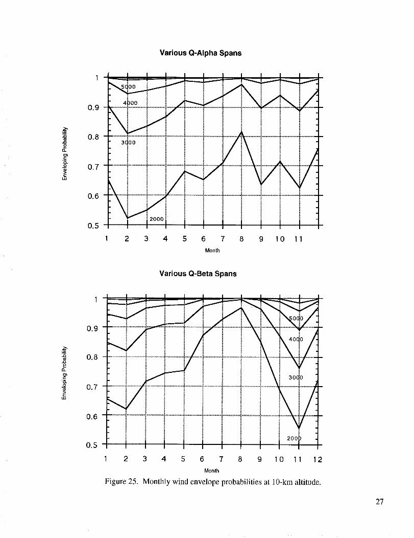
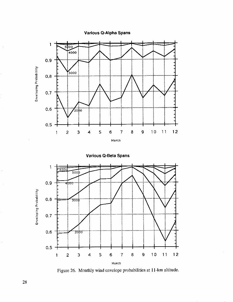
To keepascentloadswithin reasonablelevels,monthlywind biasingwaschosenasa referencefor trajectoryshaping.However,monthlymeanwind-biasedtrajectorieswerenotgenerated.Instead,thenominaltrajectorywasusedand"flown" againstmonthlyjimsphere(measured)wind profiles.Themaximumq-alphaandq-betaoccurrencesfrom eachrunwererecordedat severalaltitudes.Thesemaximumswerethenstatisticallyenvelopedto producesquatcheloidellipsesat eachaltitude.To emu-latemonthly biasing,thespanof eachellipsewasused,insteadof theactualmaximumandminimumvalues.(This is approximatelyequivalentto centeringthesquatcheloid,aswouldbedonethroughwindbiasing,but doesnot takeinto accountperformancelossesorothertrajectorydispersionswhich wouldoccurwhenwind biasingis used.)Figures25 through27showthewind envelopingpercentagefor eachmonthfor variousq-alphaandq-betaspanlevelsfor 10-,11-,and12-kmaltitudes.Thesedatacanindi-catethe approximatewind probabilitylevel thatthevehiclecouldwithstandif it werestructurallydesignedto agivenq-alphaorq-betaspancapability.At thisstage,appropriatedispersionsshouldbeaddedto thespantOaccountbothfor thesimplicity of theapproachandfor uncertaintyin theconfigura-tion data.As anexample,assumethevehiclecanwithstand+3,000 psf*deg in q-beta. Assume also that
dispersions account for 1,000 psf*deg. Then the effective q-beta limit for the vehicle would have to be
reduced by the dispersion, resulting in a q-beta limit of +2,000 psf*deg. This corresponds to a span of
4,000 psf*deg. From figure 26 (11-km altitude) this 4,000 psf*deg span limit would indicate that the
vehicle could withstand approximately 88 percent of the November winds. The wind enveloping per-
centage is higher for all other months of the year. Keeping in mind the approximations and simplicity of
the approach, these data could assist in trading wind enveloping percentage (i.e., launch probability dueto winds aloft) for vehicle structural design limits.
The adequacy of the RD-180 TVC system was examined by observing the maximum gimbal
angles and gimbal angle rates required during the ascent simulations using the jimsphere winds. Gimbal
angles were always within +2.5 °, and gimbal angle rates were within +l.5°/s. Given the 8 ° and 3°/s
gimbal angle and rate capabilities, respectively, the RD-180 TVC system should be adequate for thereference control architecture. Dispersions should fall within these capabilities also. The gimbal rate has
the least margin, and would likely be a limiting factor in choosing other control architectures (e.g., load
relief) that require higher gimbal rate capability.
26
Various Q-Alpha Spans
.wu_
.Q
£13-
t-
Q.
o
UJ
0.9
0.6
0.5
4poo
3doo
3 4 5 6 7 8 9 10 11
Month
Various Q-Beta Spans
35
£13_
c-
O
cLU
0.9
0.6
0.5
1 2
Figure 25.
2ooP
3 4 5 6 7 8 9 10 11 12
Month
Monthly wind envelope probabilities at 10-km altitude.
27
Various Q-Alpha Spans
0.9
,.Q
0.8
Q.
_o 0.7
(:LLI
0.6
0.5
1 2 3 4 5 6 7 8 9 10 11 12
Month
Various Q-Beta Spans
0.9
.J_
0.8.ooL
EL
Q.
_o 0.7
r-UJ
0.6
0.5
1 2
Figure 26.
3 4 5 6 7 8 9 10 11 12
Month
Monthly wind envelope probabilities at 1 l-km altitude.
28

Various Q-Alpha Spans
0.9
0.8o
n
o.7c
0.6
0.5
1 2 3 4 5 6 7 8 9 10 11 12
Month
Various Q-Beta Spans
0.9
(o
,= 0.8o
O_
g 0.7
UJ
0.6
0.5
1 2 3 4 5 6 7 8 9 10 11 12
Month
Figure 27. Monthly wind envelope probabilities at 12-km altitude.
29
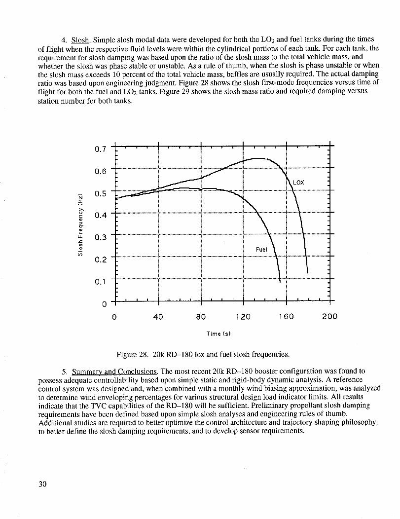
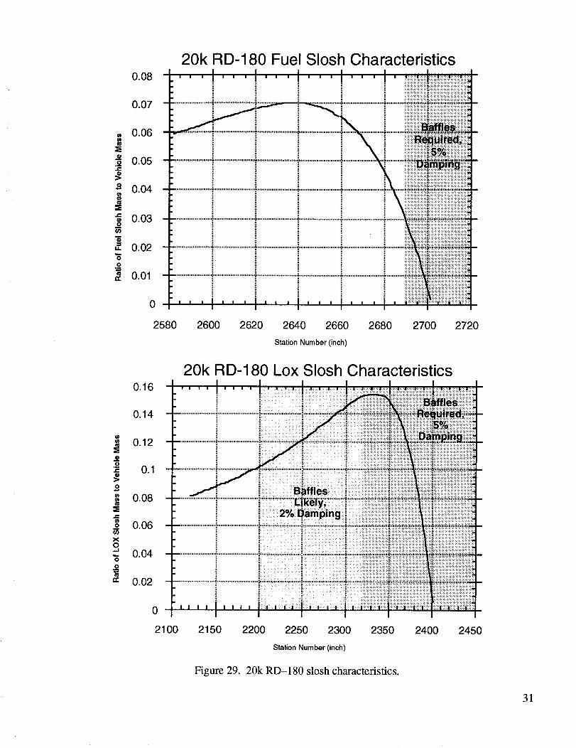
4. Slosh. Simple slosh modal data were developed for both the LO2 and fuel tanks during the times
of flight when the respective fluid levels were within the cylindrical portions of each tank. For each tank, the
requirement for slosh damping was based upon the ratio of the slosh mass to the total vehicle mass, andwhether the slosh was phase stable or unstable. As a rule of thumb, when the slosh is phase unstable or when
the slosh mass exceeds 10 percent of the total vehicle mass, baffles are usually required. The actual damping
ratio was based upon engineering judgment. Figure 28 shows the slosh first-mode frequencies versus time of
flight for both the fuel and LO2 tanks. Figure 29 shows the slosh mass ratio and required damping versusstation number for both tanks.
i-v
uc
L.
¢-
o
0.7
0.6
0.5
0.4
0.3
0.2
0.1
0
Fuel
LOX
0 40 80 120 160 200
Time (s)
Figure 28. 20k RD-180 lox and fuel slosh frequencies.
5. Summary and Conclusions. The most recent 20k RD-180 booster configuration was found to
possess adequate controllability based upon simple static and rigid-body dynamic analysis. A reference
control system was designed and, when combined with a monthly wind biasing approximation, was analyzed
to determine wind enveloping percentages for various structural design load indicator limits. All results
indicate that the TVC capabilities of the RD-180 will be sufficient. Preliminary propellant slosh damping
requirements have been defined based upon simple slosh analyses and engineering rules of thumb.Additional studies are required to better optimize the control architecture and trajectory shaping philosophy,
to better define the slosh damping requirements, and to develop sensor requirements.
3O
0.08
0.07
= 0.06
_e._ 0.05
0.04m
® 0.03O
" 0.02
0
0.01
0
20k RD-180 Fuel Slosh Characteristics
2580 2600 2620 2640 2660 2680 2700 2720
Station Number (inch)
20k RD-180 Lox Slosh Characteristicso.16 ........ I............ I...................I.............................I.......................................I......................................
0.14 .....................i.......................i"'"...................iI!'I''" iiiiiii_!_iiii_-i _ i - _::iii!iiiiiiiii!ii!iiiiiiiiiii!iS:_Niiiiiiiiiiiiiiiiiiiiiiiiii_
0
_ 0.1 ......
= 0.08 -
: : 0 : " " : .... " : ,
=® ^^^ ." 2'_ Damp,ng: . :::;iiii_ii:::iiii::::::_::_:::i::i_i::_:_:_::: _iiiiii!ii!iiiii!iiiiiiii!_iiiiiiiiiiiiiiiiii!iiiii_.0 ______ll.IIh ............................................. :",.,,. ........ ;;; ....... "................. _;.,,,-"-,.;.;;;;;:;;;;;;:;;;;;;;_;;;;;;_;_;_;_;_:;_;;; ::::::::::::::::::::::::: -
i ::::.i..i:. :_,ii!iiiii!iii!ii!'_i:iiiiiiii!iiii!!iiiiiiiiiiiiiiiiiiiiiiiiiil_!iiiiiiiiiiiiiiiiiiiiiiiiiiiiiiiiiiiiiiiiiiiii!ii_o i • i:.: :::::::-.i:i_:_i_iii_ii_i1:_::ii_i_i_::iiiiii_ii!i!iiiiiiiii_ii_iiiii_::_i_i_i::i::_::-,-,:::,:,:,:,:,,_:_:_:_:_:_:_:_:_:_:_:_:,:_:_::::..............................................
i 0.04 .............................................".......................";............,..;......_........;;,;;;;;;ii;_;_ii_ii_ii_ii;_i;i,,iiiiiiiiiiiiiiiiiii__
-= ;:: • " _i _:!!!!!!!i!!_!!!i!i!!ii::!_!:'i!i!i!i!i!iii!i!!iiiiiii!_i!!!!ii!!!i!i!ii_i_!_!_!_!!!!!i!_!_!_!i!i!_!_!i_
-: .:.. {: ========================================:,'_:_i_iiiiiiiiiii::._ = . • t :. : ::::::::::::::::::::::::::::::::::::::::::::::::::::::::::::::::::::::::::::::::::::::::::::::::::::::::::::::::::::
........................................... :,.---,"..;; ........ !-....;.-;-.;,,.,,,;_;:.;.-;._#_fi,_fi_i ifi_;_;_#_#__0.02
._ i i =:2ii=:i!;iiiiii!iiiiiiiiiiiiiiii::i::i::i::i::iiiiiii=:iiiii::)i2iiii_2ii!?:!::!:/:i=:=:i====i)=:i;iiilii!!iiiili_
I I I I
2100 2150 2200 2250 2300 2350 2400 2450
Station Number (inch)
Figure 29. 20k RD-180 slosh characteristics.
31
F. Structural Design
During this design analysis, payload trades were performed using the payload exchange ratios as
generated by the flight mechanics organization and listed in section II.D.
The material used for design was aluminum 2219-T87 with an ultimate tensile strength of 63 ksi.
Aluminum-lithium (A1-Li) would reduce the booster weight approximately 10 percent, adding 785 lb of
payload capability. A1-Li was not used because the high material cost is inconsistent with a low-cost
booster, and payload capability is not as sensitive to the booster weight as to the upper stage weight.
Composites were not considered due to the brevity of the study, but cost may be comparable with thealuminum (by using automated manufacturing) while the weight should be less than with Al-Li. Thesematerials could be inserted into the production for product enhancement as their technologies are final-
ized.
The cylindrical tanks, skirts, and intertanks were analyzed using the cylinder optimization of
rings, skin, and stringers (CORSS TM) computer program. This program was recently developed by the
Systems Strength Analysis Branch (ED24) and the Structural Development Branch (ED52) at MSFC.
The program allows an optimum or near-optimum geometry to be selected based on the design loads,dimensions (radius, length, etc.), and dimensional constraints (such as maximum stiffener height, mini-
mum skin thickness, etc.). As a part of this analysis review, checks were made against hand methods and
against another shell stability computer program. These checks led to the CORSS TM program beingmodified twice. One change was an improvement in the stringer torsional stiffness calculation, and the
other was a correction in the stringer eccentricity from the skin in the stability calculations.
The 20k booster was designed using a 2.0 ultimate safety factor. This factor of safety was chosen
per MSFC-HDBK-505 Rev. A, so that structural testing would not be required, saving schedule time
and testing costs. The skin panels between stringers were allowed to buckle at a load factor of 1.0, withthe constraint that the ultimate factor of safety was still greater than 2.0. A safety factor of 1.4 would in-
crease payload capability by 1,015 lb, but at the cost of a structural test program. A production proof test
without inspection is seen as acceptable.
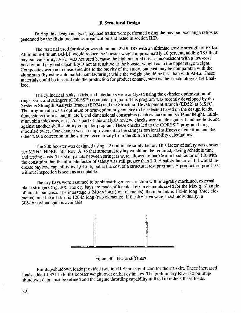
The dry bays were assumed to be skin/stringer construction with integrally machined, external
blade stringers (fig. 30). The dry bays are made of identical 60-in elements sized for the Max q, 6 ° angleof attack load case. The interstage is 240-in long (four elements), the intertank is 180-in long (three ele-
ments), and the aft skirt is 120-in long (two elements). If the dry bays were sized individually, a
306-1b payload gain is available.
Figure 30. Blade stiffeners.
Buildup/shutdown loads provided (section II.E) are significant for the aft skirt. These increasedloads added 1,431 lb to the booster weight over earlier estimates. The preliminary RD-180 buildup/
shutdown data must be refined and the engine throttling capability utilized to reduce these loads.
32

The60-inelementlengthselectedfrom acommonaltyaspectcausesinterferencewith thefeed-lines.The feedlinesneed44.96in betweendomes,andonly 38.58in areprovided(fig. 31).Layoutsusing100-inelementsinsteadof 60-inelementsseemsto eliminatetheproblemwith no weight impact.A tradeis requiredto solvethis. Penetrationsinto thedry bayswouldbe limited to a singlesegmentpanelof thecommonelements.For example,theaccessdoorandfeedlinesin the intertankwouldbeinline.
L02 TANK
RP TANK
Figure 31. Feedline/tank interference.
Isogrid/orthogrid consU_ction may reduce the dry bay weight slightly. Isogrid would add 282 lb
of payload for the 6 ° Max q loading. However, isogrid would result in 1,542 lb less payload using
buildup/shutdown loads. As the angle of attack decreases, flight loads decrease and they become lower
than the ground loads. A 1° versus 6" angle of attack at Max q loading only adds 156 lb of payload.
The tanks were baselined as skin/stringer for manufacturing and cost and are stiffened by inte-
grally machined, internal blade stringers. There are no intermediate rings due to pressure stabilization.
Slosh baffles are required in both the LO2 and RP tank, and a 5-percent damping was used to generate
the baffle weight. Due to manufacturing limitations the LO2 tank will need a circumferential weld.
However, a constant cross section was maintained so that the two halves would be identical for ease of
manufacturing. Isogrid/orthogrid tanks would be lighter due to the more efficient load can'ying in the
hoop direction. Isogrid tanks could add 1,031 lb of payload capability. To eliminate Y-rings, the inter-faces to the tanks are through welded stubs with external bolt flanges (fig. 32), but this requires slightly
different diameters for the dry bays and tanks.
The tank domes are square root of two elliptical domes to minimize vehicle stack length without
requiring stiffening of the domes. They are sized for the required weld thickness to eliminate the needfor machined weld lands. The fore LO2 and both RP domes are identical. Four individual, weld-
thickness domes with four new weld schedules would add 141 lb of payload. Four individual domes,
with weld lands, add 632 lb of payload. Tank penetrations are limited to the top access holes and bottom
propellant outlet.
33

/
Figure 32. Tank/dry bay interface.
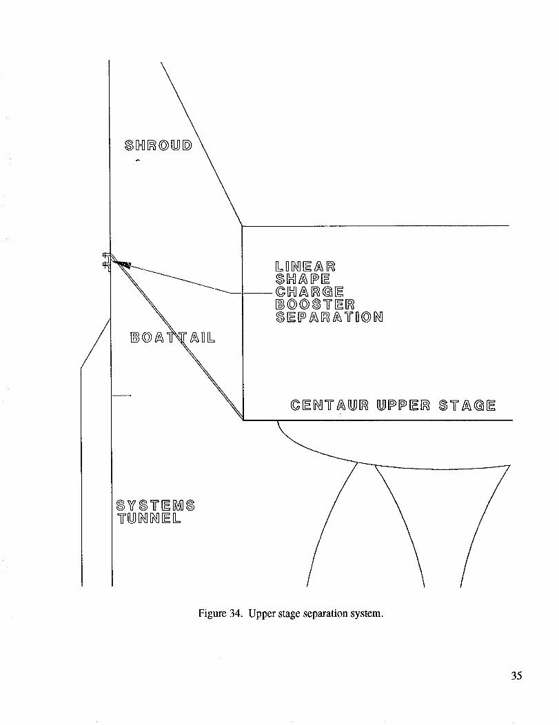
The vehicle lift-off (fig. 33) and upper stage separation systems are linear-shaped charges (fig.
34). This system provides well-distributed loads into the vehicle and is currently being investigated as an
improvement to the shuttle holddown. Since the shroud is still attached when the booster is separated,
payload and upper stage contamination is not a concern.
RETRACTABLE _
PAD HOLD-DOWN
LINEAR SEPARATION SYSTEM
(e.g. SHAPE CHARGE )
AERO COVER
AFT SKIRT
25.6 -_
_ t_ THRUSTuR E
U 155 DIA
Figure 33. Holddown.
34
8VSY_Ii_8
Figure 34. Upper stage separation system.
35
1. $0mm_u'y of P¢rf0rmed Weight Trades.
Aluminum baseline versus A1-Li
A1-Li saves 2,952 lb of booster weight, yielding a 785-1b payload increase based on approximate
weight savings using A1-Li.
2.0 safety factor baseline versus 1.4
1.4 saves 3,816 lb of booster weight, yielding a 1,015-1b payload increase using commonelements.
6* Max-q loads baseline versus buildup/shutdown
Buildup/shutdown adds 1,628 lb of booster weight, reducing the payload by 433 lb.
60-in dry bay elements baseline versus l O0-in baselineThe 100-in baseline does not significantly change the booster weight and seems to eliminatefeedline interference.
Skin�stringer dry bay baseline versus isogrid
(1) Isogrid saves 1,060 lb of booster weight, yielding a 282-1b payload increase based on Max q
loading.
(2) Isogrid adds 5,798 lb of booster weight, yielding a 1,542-1b payload decrease based on
buildup/shutdown loading.
Skin�stringer tank baseline versus isogridIsogrid saves 3,876 lb of booster weight, yielding a 1,031-1b payload increase.
Common dry bay baseline versus individual dry bays
Individual dry bays save 1,150 lb of booster weight, yielding a 306-1b payload increase.
6 °Max q baseline versus 1 ° Max q
1° saves 587 lb of booster weight, yielding a 156-1b payload increase. Ground wind becomes the
design driver, buildup/shutdown loading not included.
Two weld thickness domes baseline versus four weld thickness domes
Individual domes save 530 lb of booster weight for a 141-1b payload increase
Two weld thickness domes baseline versus four individual domes with weld lands
Individual domes save 2,376 lb of booster weight, yielding a 632-1b payload increase
G. Propulsion Systems
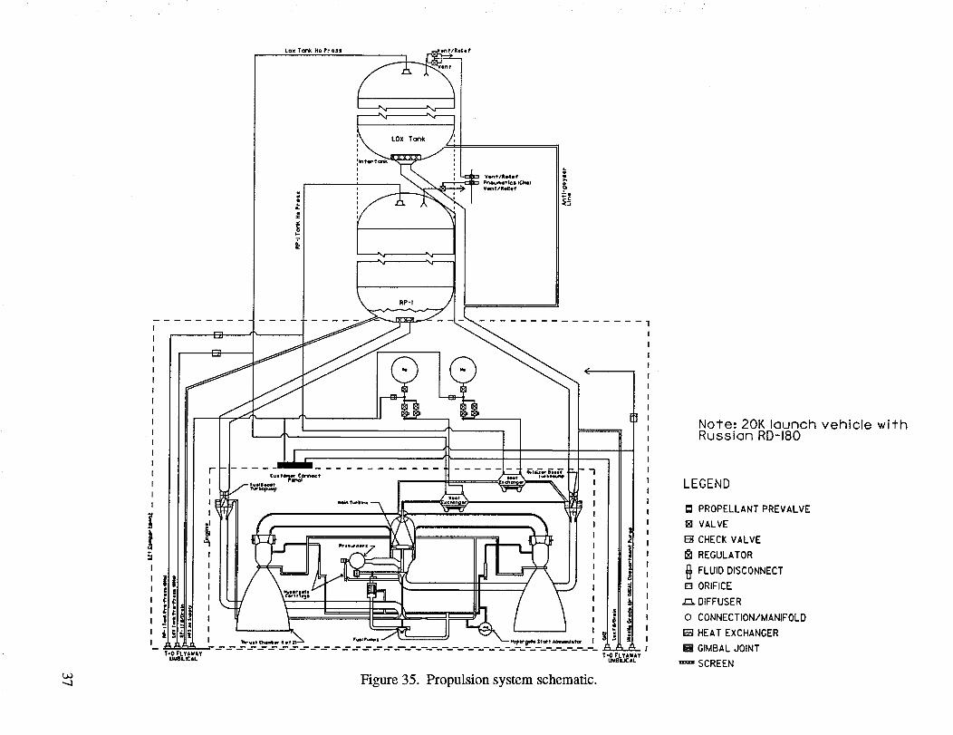
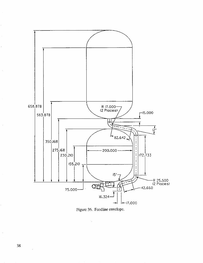
1. Description. The schematic of the propulsion system is shown in figure 35. Feedline
envelopes are shown in figure 36. The fuel sump and line envelope shown are worst case and will be
refined when aft compartment clearances and RD-180 inlet locations are identified. Seventeen-inch
feedlines for the oxidizer are assumed in order to utilize qualified shuttle hardware. The fuel feedlines
are 12 inches in diameter. Propulsion system components other than the RD-180 engine are listed in
table 3. It is assumed that two engine-supplied heat exchangers are available to pressurize the fuel andLO2 tanks.
36
Lox Tonk He Press ent/Rel;e f
knter took i
r
RP-I
|
!
J
1|
t
T"O FLYAWAYUMOILICAL
Figure 35. Propulsion system schematic.
Note: 20K launch vehicle withRussian RD-180
LEGEND
PROPELLANT PREVALVE
[] VALVE
F-_CHECK VALVE
REGULATOR
FLUID DISCONNECT
[] ORIFICE
,E3.DIFFUSER
0 CONNECTION/MANIFOLD
EaHEAT EXCHANGER
B GIMBAL JOINT
=_SCREEN
//f-_
658.878
583.878
350.168
275.168
230.210
155.210
75.000--
--'_ J
lace__
-- 200.000 _i i
I5.000
A
172.733
15L._ _R 25.500
•16"324L "-- 17.000
Figure 36. Feedline envelope.
38
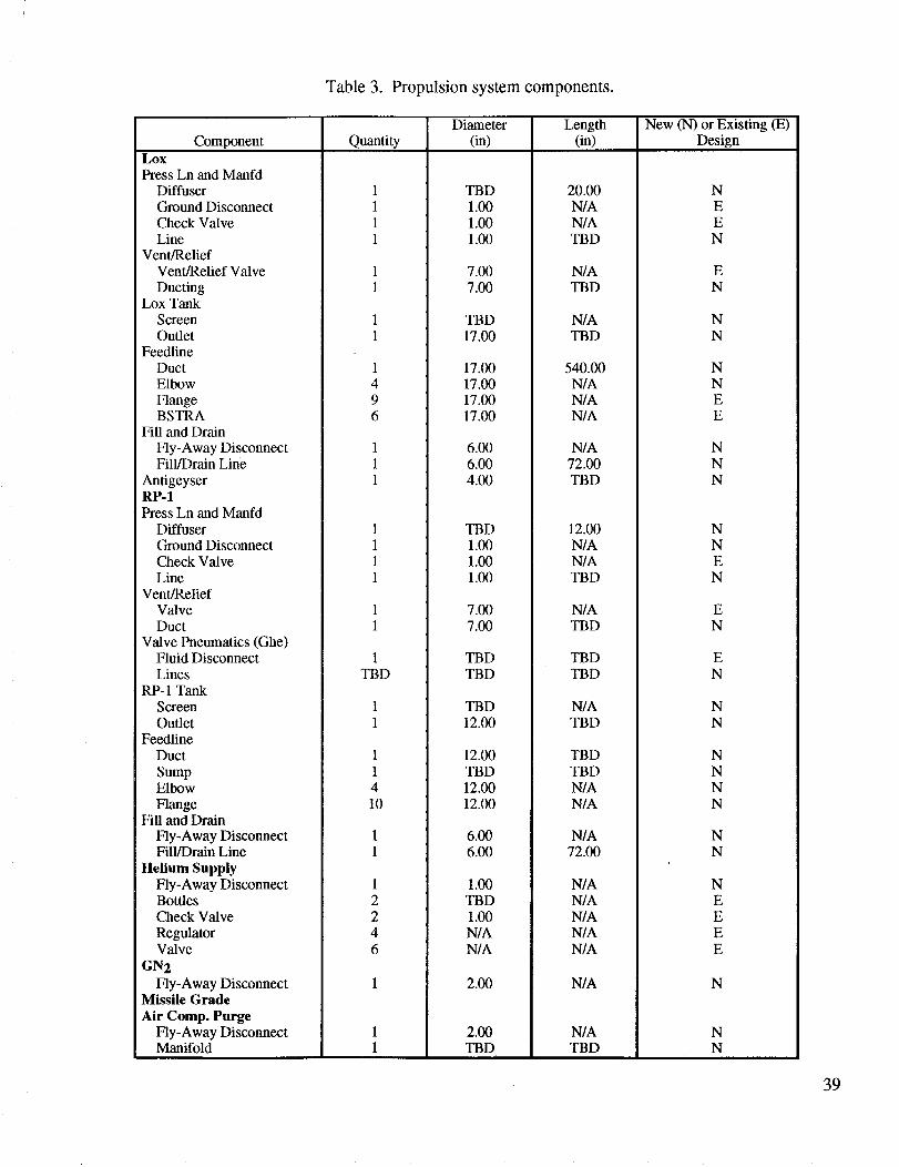
Table 3. Propulsion system components.
Diameter Length New (N) or Existing (E)Component Quantity (in) (in) Design
Lox
Press Ln and ManfdDiffuser
Ground DisconnectCheck ValveLine
Vent/ReliefVent/Relief Valve
DuctingLox Tank
ScreenOutlet
FeedlineDuct
Elbow
FlangeBSTRA
Fill and Drain
Fly-Away DisconnectFill/Drain Line
AntigeyserRP-1Press Ln and Manfd
DiffuserGround DisconnectCheck ValveLine
Vent/ReliefValveDuct
Valve Pneumatics (Ghe)Fluid DisconnectLines
RP- 1 TankScreenOutlet
FeedlineDuct
SumpElbow
FlangeFill and Drain
Fly-Away DisconnectFill/Drain Line
Helium SupplyFly-Away DisconnectBottlesCheck Valve
RegulatorValve
GN2
Fly-Away DisconnectMissile Grade
Air Comp. PurgeFly-Away DisconnectManifold
1TBD
11410
TBD
1.001.001.00
7.007.00
TBD17.00
17.00
20.00N/AN/ATBD
N/ATBD
N/ATBD
540.0017.0017.0017.00
6.006.004.00
TBD1.001.001.00
7.007.00
TBDTBD
TBD12.00
12.00TBD12.0012.00
6.006.00
1.00TBD1.00N/AN/A
2.00
2.00TBD
N/AN/AN/A
N/A72.00TBD
12.00N/AN/ATBD
N/ATBD
TBDTBD
N/ATBD
TBDTBDN/AN/A
N/A72.00
N/AN/AN/A
N/AN/A
N/A
N/ATBD
NEEN
E
N
NN
NNEE
N
NN
NN
EN
EN
EN
NN
NNNN
NN
NEE
EE
N
NN
39
Functionssupportedby thepropulsionsystemare:
• Rocketpropulsion(RD-180engine)
• Fuel (RP-1) fill, drain,andenginesupply
• Oxidizer (LO2)fill, drain,andenginesupply
• Pressurizationof thefuelandoxidizertankswith heatedhelium
• Groundsupplyof pressurizationHe
• Prepressurizationof thefuel andoxidizertankswith ground-suppliedHe
• Groundsupplyof gaseousnitrogento theengine
• Groundsupplyof missilegradeair to theengineandto purgetheaft compartment
• Fuel and oxidizer tank vent and relief
• Geyser avoidance during oxidizer tank fill.
No purge has been provided to the forward compartment or intertank areas. Missile-grade air has been
supplied to the aft compartment to provide environmental conditioning for the avionics equipment.
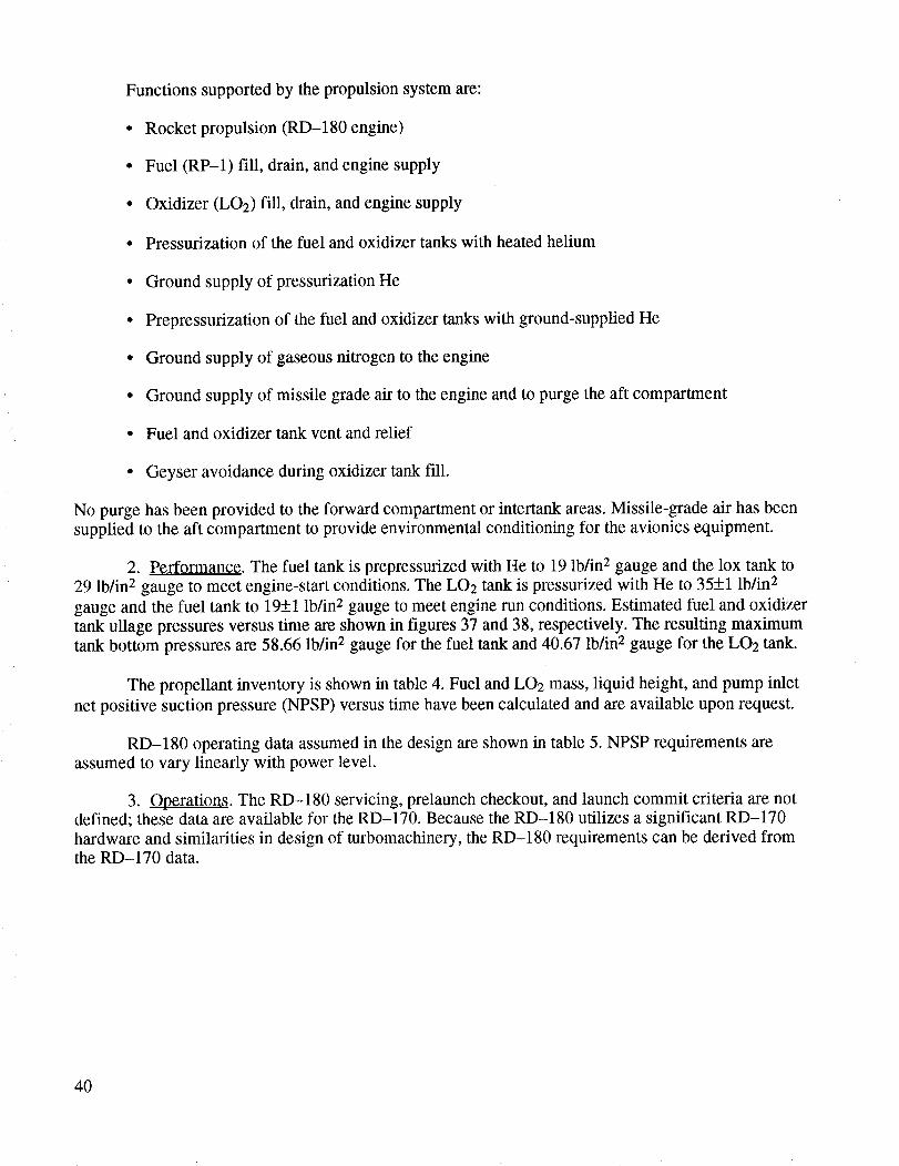
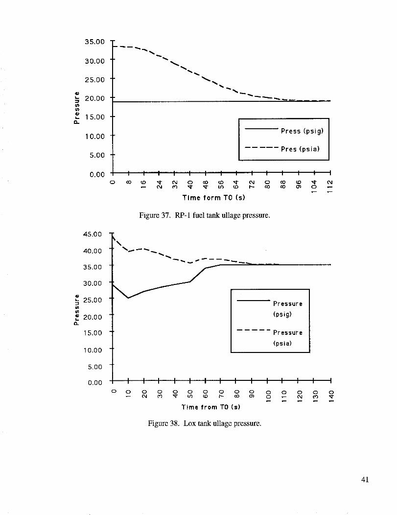
2. Performance. The fuel tank is prepressurized with He to 19 lb/in 2 gauge and the lox tank to
29 lb/in 2 gauge to meet engine-start conditions. The LO2 tank is pressurized with He to 35+1 lb/in 2
gauge and the fuel tank to 19+1 lb/in 2 gauge to meet engine run conditions. Estimated fuel and oxidizer
tank ullage pressures versus time are shown in figures 37 and 38, respectively. The resulting maximum
tank bottom pressures are 58.66 lb/in 2 gauge for the fuel tank and 40.67 lb/in 2 gauge for the LO2 tank.
The propellant inventory is shown in table 4. Fuel and LO2 mass, liquid height, and pump inlet
net positive suction pressure (NPSP) versus time have been calculated and are available upon request.
RD-180 operating data assumed in the design are shown in table 5. NPSP requirements areassumed to vary linearly with power level.
3. Operations. The RD-180 servicing, prelaunch checkout, and launch commit criteria are notdefined; these data are available for the RD-170. Because the RD-180 utilizes a significant RD-170
hardware and similarities in design of turbomachinery, the RD-180 requirements can be derived fromthe RD-170 data.
4O
35.00 "
30.00
25.00
qM
'- 20.00in(/)_p_- 1 5.00
10.00
5.00
0.00
45.00
40.00
35.00
30.00
_- 25.00
20.00ca.
15.00
10.00
5.00
0.00
Press (psig)
Pres (psia)
0
I I I I I I I I I ; ; ; ; ;
CO _0 _I" 04 0 QO _0 _ 04 0 O0 _0 _l" 0404 _ _I" _I" If) _0 I-- O0 CO O_ 0 ,--
Time form TO (s)
Figure 37. RP-1 fuel tank ullage pressure.
Pressure
(psig)
Pressure
(psia)
o 0 o o o04 o3 _"
Figure 38.
0 0 0 0 0 0 0 0 0 0LID _0 t'-- CO 0") 0 _ 04 (_1 W"
Time from TO (s)
Lox tank ullage pressure.
41

Table4. Propellantinventory.
20k Vehicle Propellant Inventory Summary
Total Propellant Required (Ibm) 590,555
Mixture Ratio (O/F) 2.6
Propellants lox kerosene helium
Propellant Mass Requirement (Ibm) 426,512 164,043 TBD
Stage Diameter (nominal inches) 200.00 200.00
Unusable
Tank Residuals (Ibm) 0 300 TBD
Feedline and Pump Residuals (Ibm) 1,200 500
Booster Shutdown Consumption (ibm) 700 270
Gas Residuals (Ibm) 0 0 TBD
Prestart Boiloff (Ibm) 100 0
Start Consumption (Ibm) 520 200
Onboard at Lift-Off (Ibm) 429,232 165,513
Propellant Density (lbm/ft 3) 71.130 51
Feed System Volume (ft 3) 75.00 15.00
Mass in Feedline (Ibm) 5,334.75 765
908.85Total Dome Volume (3/4 ellipse) ft 3
Ullage Height (in) 20.00
908.85
12.00
Liquid Volume in Dome (ft 3) 820.53 875.82
Ullage Volume (ft 3) 88.33 33.04
Percent Ullage by Volume (Ibm, cryo-unpressurized) 1.46 1.01
Equivilent Ullage Mass (Ibm) 6,283 1,685
Total Tank Capacity (Ibm, cryo-unpressurized) 430,180 166,433
Total Tank Volume (ft 3, cryo-unpressurized) 6,048 3,263
"Fable 5. RD-180 estimated operating data.
PercentPowerLevel
Thrust(lbf)
40 367,917.06
50 459,896.3
74
80
100
102
680,646.6
735,834.1
919,792.65
938,188.5
ISP (s) MR
335 2.42
335 2.55
335 2.69
335 2.67
335 2.6
335 2.78
Lox NPSP RP-1 mdot mdot Pc(lb/in 2 (lb/in 2 Lox RP-1 (lb/in 2
absolute) absolute) (lb/s) (lb/s) absolute)
18.5 11.4 994.4 389
1,524.6 567
1,670 623.7
38.4 17.1 1,928.3 762.83 3,560
2,024.4 779.1
RD-180 estimated data scaled off of the RD-170 test data.Engine has been uprated 5 percent to meet the design requirements of the 20k booster.
42
H. Avionics Systems
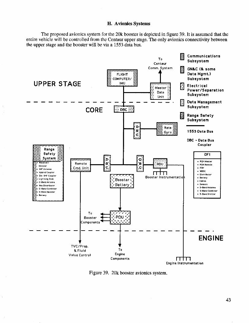
The proposed avionics system for the 20k booster is depicted in figure 39. It is assumed that the
entire vehicle will be controlled from the Centaur upper stage. The only avionics connectivity between
the upper stage and the booster will be via a 1553 data bus.
UPPER STAGE
To BCentaur
_"IN'_""_'_'_"_\"""'_NIcoMPUTER/FLIGHT _ C°mmiystem B
I_. ..... i_u..... ._
B[::!Data:-]E Unit :-'l
CORE --: '-:1 B
t'_°_°t""':_rCm_.,,,S"°°'.,,,.d _
[_"Ba.t.te.ry,_'l
lBooster _----[,;,PDU ""I
:omponents_---1.:,:,:,:,:,:,l
iTVC/Prop.
& Fluid
Valve Control
To
EngineComponents
CommunicationsSubsystem
GN&C (& some
Data Mgmt.)Subsystem
ElectricalPower/Separat IonSubsystem
Data ManagementSubsystem
Range SafetySubsystem
1553 Data Bus
DBC - Data Bus
Coupler
FTq-1Engine Instrumentation
DFI
• PCM Master
• PCM Remote
• FDM
• WBSC
• Distributor
• Battery
• Cables
• Sensors
• S-Band Antenna
• SoBand Combiner
• S-Band Xmltter
ENGINE
Figure 39. 20k booster avionics system.
43
Nonflight-critical data from the booster and engines will be collected by a remote data unit
located on the booster stage and transferred directly to a master data unit on the Centaur upper stage for
downlink via the Centaur S-band communications system. Flight-critical data from the booster will be
collected by a remote command unit on the booster stage and routed directly to the Centaur flight
computer/internal measurement unit (IMU). The flight computer/IMU subsequently passes the data tothe master data unit for downlink via the Centaur S-band communications system. Commands from the
Centaur flight computer/IMU for control of the booster engines, thrust vector, and fluid valves will be
routed via the 1553 data bus through the remote command unit to the appropriate end items. It is
assumed that a rate gyro will be necessary on the booster stage. Data from the rate gyro will be output to
the flight computer/IMU via the 1553 data bus.
For the sake of design simplicity and weight, a separate power subsystem is envisioned for the
booster stage. Power from the Ag-Zn battery power source will be distributed to the booster avionics
components, as well as to the engine and TVC components via a power distribution unit. A separate
battery will power the Centaur upper stage avionics components.
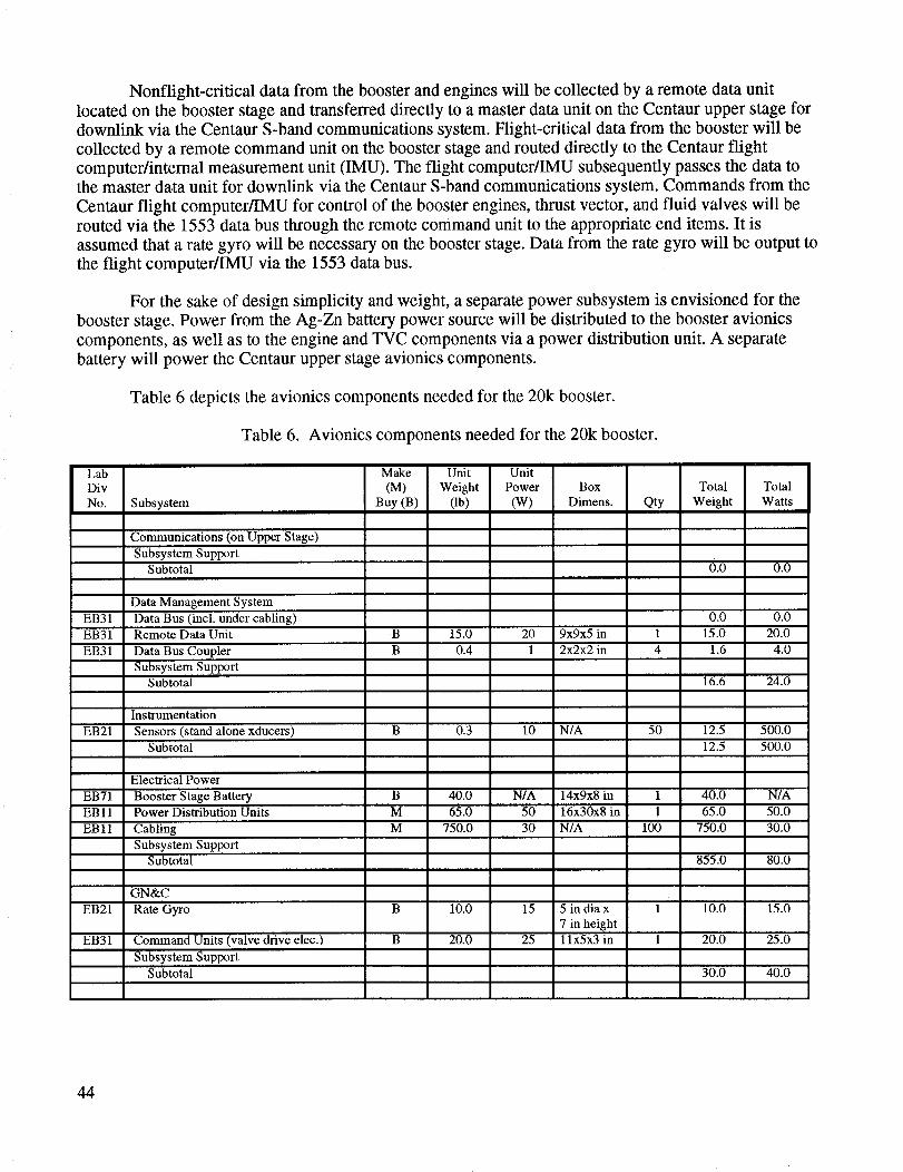
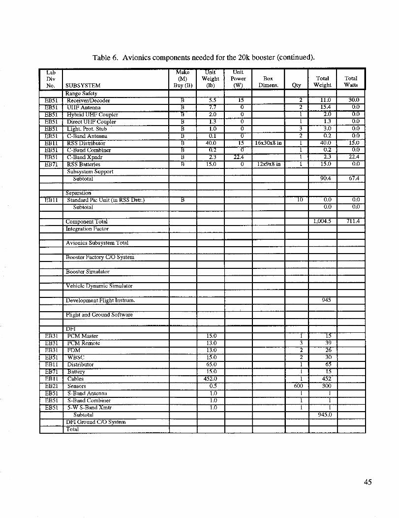
Table 6 depicts the avionics components needed for the 20k booster.
Table 6. Avionics components needed for the 20k booster.
Lab Make Unit Unit
Div (M) Weight Power Box Total Total
No. Subsystem Buy (B) (lb) (W) Dimens. Qty Weight Watts
Communications (on Upper Stage)
Subsystem SupportSubtotal 0.0 0.0
0.0 0.0
15.0 20.0
1.6 4.0
16.6 24.0
12.5 500.0
12.5 500.0
Data Management System
EB31 Data Bus (incl. under cabling)
EB31 Remote Data Unit B 15.0 20 9x9x5 in 1
EB31 Data Bus Coupler B 0.4 1 2x2x2 in 4
Subsystem Support
Subtotal
Instrumentation
EB21 Sensors (stand alone xducers) B 0.3 10 N/A 50
Subtotal
Electrical Power
EB71 Booster Stage Battery B 40.0 N/A 14x9x8 in 1
EBI1 Power Distribution Units M 65.0 50 16x30x8 in 1
EB 11 Cabling M 750.0 30 N/A 100
Subsystem SupportSubtotal
40.0 N/A
65.0 50.0
750.0 30.0
855.0 80.0
GN&C
EB21 Rate Gyro B 10.0 15 5 in dia x 1
7 in height
EB31 Command Units (valve drive elec.) B 20.0 25 11x5x3 in 1
Subsystem Support
Subtotal
10.0 15.0
20.0 25.0
30.0 40.0
44
Lab
Div
No.
EB51
EB51
EB51
EB51
EB51
EB51
EB11
EB51
EB51
EB71
EB11
EB31
EB31
EB31
EB51
EB11
EB71
EBll
EB21
EB51
EB51
EB51
Table 6. Avionics components needed for the 20k booster (continued).
SUBSYSTEM
Range Safety
Make Unit Unit
(M) Weight Power Box
Buy (B) (lb) (W) Dimens.
Receiver/Decoder B 5.5 15
UHF Antenna B 7.7 0
Hybrid UHF Coupler B 2.0 0
Direct UHF Coupler B 1.3 0
Light. Prot. Stub B 1.0 0C-Band Antenna B 0.1 0
RSS Distributor B 40.0 15 16x30x8 in
C-Band Combiner B 0.2 0
C-Band Xpndr B 2.3 22.4
RSS Batteries B 15.0 0 12x9x8 in
Subsystem Support
Subtotal
Qty
Total Total
Weight Watts
2 11.0 30.0
2 15.4 0.0
1 2.0 0.0
1 1.3 0.0
3 3.0 0.0
2 0.2 0.0
1 40.0 15.0
1 0.2 0.0
1 2.3 22.4
1 15.0 0.0
90.4 67.4
10 0.0 0.0
0.0 0.0
1,004.5 711.4
945
15
39
26
Separation
Standard Pic Unit (in RSS Dstr.)
Subtotal
Component Total
Integration Factor
Avionics Subsystem Total
Booster Factory C/O System
Booster Simulator
Vehicle Dynamic Simulator
Development Flight Instrum.
Flight and Ground Software
DFI
PCM Master
PCM Remote
FDM
WBSC
Distributor
Battery
Cables
Sensors
S-Band Antenna
S-Band Combiner
5-W S-Band Xmtr
Subtotal
DFI Ground C/O System
Total
15.0
13.0
13.0
15.0
65.0
15.0
452.0
0.5
1.0
1.0
1.0
1
3
2
2
1
1
1
600
1
1
1
30
65
15
452
300
1
1
1
945.0
45
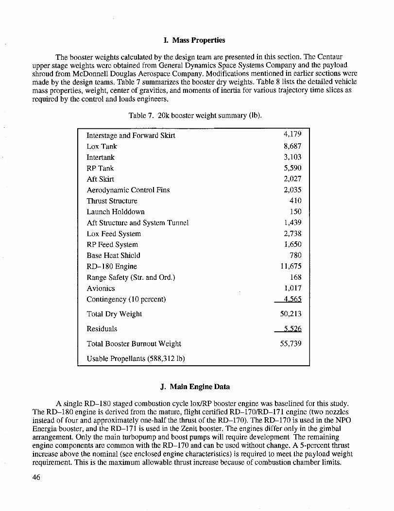
I. Mass Properties
The booster weights calculated by the design team are presented in this section. The Centaur
upper stage weights were obtained from General Dynamics Space Systems Company and the payloadshroud from McDonnell Douglas Aerospace Company. Modifications mentioned in earlier sections were
made by the design teams. Table 7 summarizes the booster dry weights. Table 8 lists the detailed vehicle
mass properties, weight, center of gravities, and moments of inertia for various trajectory time slices as
required by the control and loads engineers.
Table 7. 20k booster weight summary (lb).
Interstage and Forward Skirt
Lox Tank
Intertank
RP Tank
Aft Skirt
Aerodynamic Control Fins
Thrust Structure
Launch Holddown
Aft Structure and System Tunnel
Lox Feed System
RP Feed System
Base Heat Shield
RD-180 Engine
Range Safety (Str. and Ord.)
Avionics
Contingency (10 percent)
Total Dry Weight
Residuals
Total Booster Burnout Weight
4,179
8,687
3,103
5,590
2,027
2,035
410
150
1,439
2,738
1,650
780
11,675
168
1,017
4,565
50,213
5,526
55,739
Usable Propellants (588,312 lb)
J. Main Engine Data
A single RD-180 staged combustion cycle lox/RP booster engine was baselined for this study.
The RD-180 engine is derived from the mature, flight certified RD-170/RD-171 engine (two nozzles
instead of four and approximately one-half the thrust of the RD-170). The RD-170 is used in the NPO
Energia booster, and the RD-171 is used in the Zenit booster. The engines differ only in the gimbal
arrangement. Only the main turbopump and boost pumps will require development The remaining
engine components are common with the RD-170 and can be used without change. A 5-percent thrust
increase above the nominal (see enclosed engine characteristics) is required to meet the payload weight
requirement. This is the maximum allowable thrust increase because of combustion chamber limits.
46

PD24
Description
PayloadShroudNoseShroudCylinderShroud/PayloadSuppCentaurFwdStrLH2 Tank+ SysLox Tank+ SysAft Str+ PropSysRL10-A4EngineCentaurUsableLoxCentaurUsableLH2BoosterFwd StrLox Tank+ SysIntertank+ SysRPTank+ SysAft Skirt + Prop SysAero Fins
RD- 180 Engine
Usable Lox (L.O.)
Usable RP (L.O.)
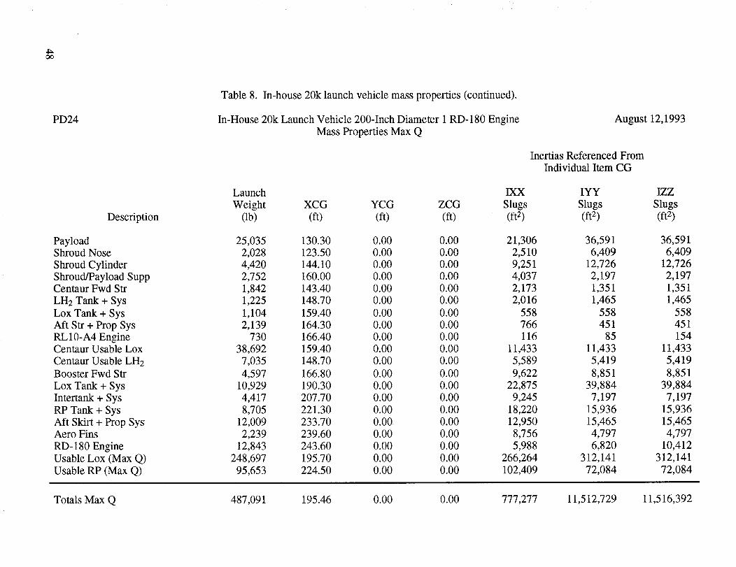
Table 8. In-house 20k launch vehicle mass properties.
In-House 20k Launch Vehicle 200-Inch Diameter 1 RD-180 Engine
Mass Properties Lift-Off
August 12,1993
Inertias Referenced From
Individual Item CG
Launch IXX IYY IZZ
Weight XCG YCG ZCG Slugs Slugs Slugs(lb) (ft) (ft) (ft) (ft 2) (ft 2) (ft 2)
25,035 130.30 0.00 0.00 21,306
2,028 123.50 0.00 0.00 2,510
4,420 144.10 0.00 0.00 9,2512,752 160.00 0.00 0.00 4,037
1,842 143.40 0.00 0.00 2,173
1,225 148.70 0.00 0.00 2,016
1,104 159.40 0.00 0.00 5582,139 164.30 0.00 0.00 766
730 166.40 0.00 0.00 116
38,692 159.40 0.00 0.00 11,433
7,035 148.70 0.00 0.00 5,589
4,597 166.80 0.00 0.00 9,622
10,929 190.30 0.00 0.00 22,875
4,417 207.70 0.00 0.00 9,245
8,705 221.30 0.00 0.00 18,220
12,009 233.70 0.00 0.00 12,950
2,239 239.60 0.00 0.00 8,756
12,843 243.60 0.00 0.00 5,988
424,892 189.90 0.00 0.00 454,904
163,420 221.00 0.00 0.00 174,963
36,591 36,591
6,409 6,409
12,726 12,726
2,197 2,1971,351 1,351
1,465 1,465
558 558
451 45185 154
11,433 11,433
5,419 5,419
8,851 8,851
39,884 39,884
7,197 7,197
15,936 15,936
15,465 15,465
4,797 4,797
6,820 10,412
1,121,380 1,121,380
191,819 191,819
Totals Lift-Off 731,053 194.05 0.00 0.00 777,277 13,610,566 13,614,229
4_
4:_O_
PD24
Description
PayloadShroud Nose
Shroud Cylinder
Shroud/Payload SuppCentaur Fwd Str
LH2 Tank + Sys
Lox Tank + Sys
Aft Str + Prop Sys
RL10-A4 EngineCentaur Usable Lox
Centaur Usable LH2
Booster Fwd Str
Lox Tank + Sys
Intertank + Sys
RP Tank + Sys
Aft Skirt + Prop SysAero Fins
RD- 180 Engine
Usable Lox (Max Q)
Usable RP (Max Q)
Table 8. In-house 20k launch vehicle mass properties (continued).
In-House 20k Launch Vehicle 200-Inch Diameter 1 RD-180 Engine
Mass Properties Max Q
August 12,1993
Inertias Referenced From
Individual Item CG
Launch IXX IYY IZZ
Weight XCG YCG ZCG Slugs Slugs Slugs(lb) (ft) (ft) (ft) (ft 2) (ft 2) (ft z)
25,035 130.30 0.00 0.00 21,306
2,028 123.50 0.00 0.00 2,510
4,420 144.10 0.00 0.00 9,2512,752 160.00 0.00 0.00 4,037
1,842 143.40 0.00 0.00 2,1731,225 148.70 0.00 0.00 2,016
1,104 159.40 0.00 0.00 558
2,139 164.30 0.00 0.00 766730 166.40 0.00 0.00 116
38,692 159.40 0.00 0.00 11,4337,035 148.70 0.00 0.00 5,589
4,597 166.80 0.00 0.00 9,622
10,929 190.30 0.00 0.00 22,875
4,417 207.70 0.00 0.00 9,245
8,705 221.30 0.00 0.00 18,220
12,009 233.70 0.00 0.00 12,950
2,239 239.60 0.00 0.00 8,756
12,843 243.60 0.00 0.00 5,988
248,697 195.70 0.00 0.00 266,264
95,653 224.50 0.00 0.00 102,409
36,591 36,5916,409 6,409
12,726 12,726
2,197 2,197
1,351 1,351
1,465 1,465558 558
451 451
85 154
11,433 11,433
5,419 5,419
8,851 8,851
39,884 39,8847,197 7,197
15,936 15,936
15,465 15,465
4,797 4,797
6,820 10,412
312,141 312,141
72,084 72,084
Totals Max Q 487,091 195.46 0.00 0.00 777,277 11,512,729 11,516,392
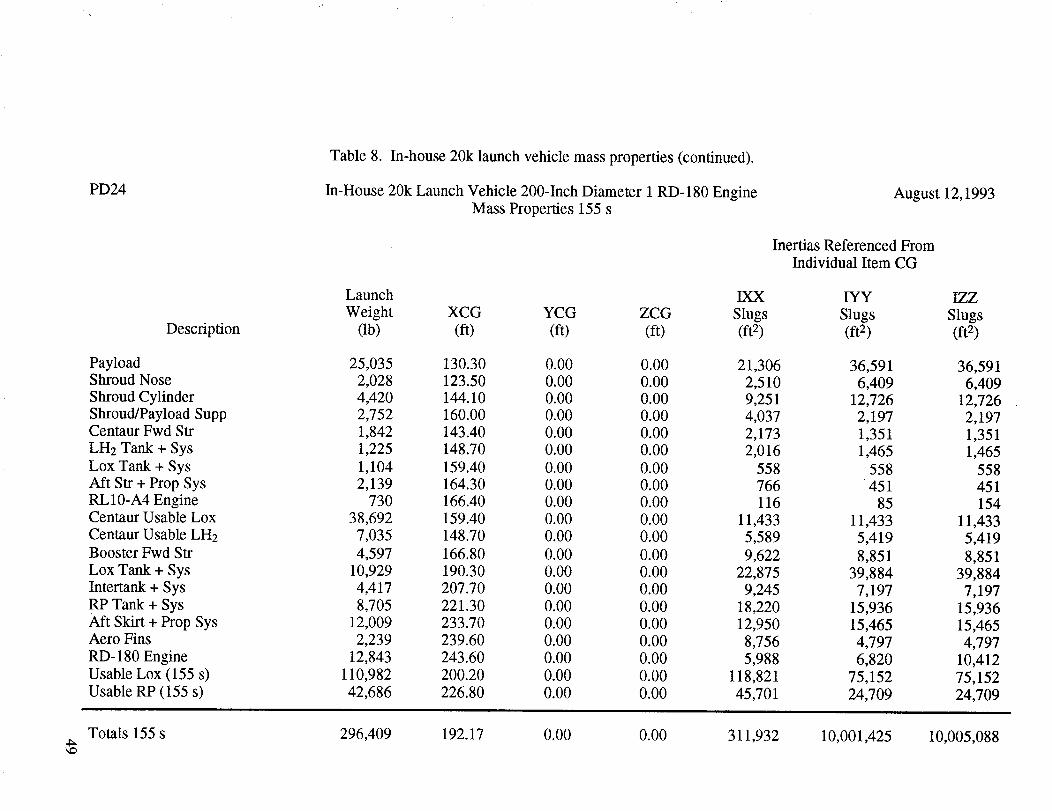
PD24
Description
PayloadShroudNoseShroudCylinderShroud/PayloadSuppCentaurFwdStrLH2Tank+ SysLox Tank+ SysAft Str+ PropSysRL10-A4EngineCentaurUsableLoxCentaurUsableLH2BoosterFwdStrLox Tank+ SysIntertank+ SysRPTank+ SysAft Skirt + PropSysAeroFinsRD-180EngineUsableLox (155s)UsableRP(155s)
Table8. In-house20k launchvehiclemassproperties(continued).
In-House20kLaunchVehicle200-InchDiameter1RD-180EngineMassProperties155s
August12,1993
InertiasReferencedFromIndividual ItemCG
Launch IXX IYY IZZWeight XCG YCG ZCG Slugs Slugs Slugs
(lb) (ft) (ft) (ft) (ft2) (ft2) (ft2)
25,035 130.30 0.00 0.00 21,3062,028 123.50 0.00 0.00 2,5104,420 144.10 0.00 0.00 9,2512,752 160.00 0.00 0.00 4,0371,842 143.40 0.00 0.00 2,1731,225 148.70 0.00 0.00 2,0161,104 159.40 0.00 0.00 5582,139 164.30 0.00 0.00 766
730 166.40 0.00 0.00 11638,692 159.40 0.00 0.00 11,4337,035 148.70 0.00 0.00 5,5894,597 166.80 0.00 0.00 9,622
10,929 190.30 0.00 0.00 22,8754,417 207.70 0.00 0.00 9,2458,705 221.30 0.00 0.00 18,220
12,009 233.70 0.00 0.00 12,9502,239 239.60 0.00 0.00 8,756
12,843 243.60 0.00 0.00 5,988110,982 200.20 0.00 0.00 118,82142,686 226.80 0.00 0.00 45,701
36,5916,409
12,7262,1971,3511,465
558451
8511,4335,4198,851
39,8847,197
15,93615,4654,7976,820
75,15224,709
36,5916,409
12,7262,1971,3511,465
558451154
11,4335,4198,851
39,8847,197
15,93615,4654,797
10,41275,15224,709
Totals155s 296,409 192.17 0.00 0.00 311,932 10,001,425 10,005,088

PD24
Description
PayloadShroudNoseShroudCylinderShroud/PayloadSuppCentaurFwdStrLH2 Tank+ SysLox Tank+ SysAft Str+ PropSysRL10-A4EngineCentaurUsableLoxCentaurUsableLH2BoosterFwdStrLox Tank+ SysIntertank+ SysRPTank+ SysAft Skirt + Prop SysAero Fins
RD- 180 Engine
Table 8. In-house 20k launch vehicle mass properties (continued).
In-House 20k Launch Vehicle 200-Inch Diameter 1 RD-180 Engine
Mass Properties Booster B.O.
August 12,1993
Inertias Referenced From
Individual Item CG
Launch IXX IYY IZZ
Weight XCG YCG ZCG Slugs Slugs Slugs(lb) (ft) (ft) (ft) (ft 2) (ft 2) (ft 2)
25,035 130.30 0.00 0.00 21,306
2,028 123.50 0.00 0.00 2,5104,420 144.10 0.00 0.00 9,251
2,752 160.00 0.00 0.00 4,037
1,842 143.40 0.00 0.00 2,173
1,225 148.70 0.00 0.00 2,016
1,104 159.40 0.00 0.00 558
2,139 164.30 0.00 0.00 766730 166.40 0.00 0.00 116
38,692 159.40 0.00 0.00 11,433
7,035 148.70 0.00 0.00 5,589
4,597 166.80 0.00 0.00 9,622
10,929 190.30 0.00 0.00 22,875
4,417 207.70 0.00 0.00 9,245
8,705 221.30 0.00 0.00 18,220
12,009 233.70 0.00 0.00 12,950
2,239 239.60 0.00 0.00 8,756
12,843 243.60 0.00 0.00 5,988
36,591
6,40912,726
2,197
1,351
1,465
558
451
85
11,4335,419
8,851
39,884
7,197
15,936
15,465
4,797
6,820
36,591
6,40912,726
2,197
1,351
1,465
558
451
154
11,433
5,419
8,851
39,884
7,197
15,936
15,465
4,797
10,412
Totals Booster B.O. 142,741 175.57 0.00 0.00 147,410 6,864,834 6,868,497
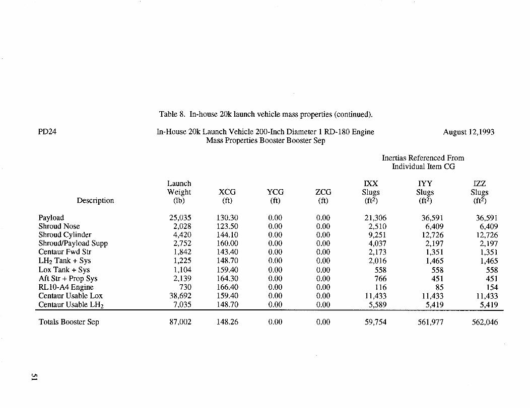
PD24
Description
Table8. In-house20klaunchvehiclemassproperties(continued).
In-House20kLaunchVehicle200-InchDiameter1RD-180EngineMassPropertiesBoosterBoosterSep
August12,1993
InertiasReferencedFromIndividual ItemCG
Launch IXX IYY IZZWeight XCG YCG ZCG Slugs Slugs Slugs
(lb) (ft) (ft) (ft) (ft2) (ft2) (ft 2)
Payload 25,035 130.30 0.00 0.00 21,306 36,591 36,591
Shroud Nose 2,028 123.50 0.00 0.00 2,510 6,409 6,409
Shroud Cylinder 4,420 144.10 0.00 0.00 9,251 12,726 12,726
Shroud/Payload Supp 2,752 160.00 0.00 0.00 4,037 2,197 2,197Centaur Fwd Str 1,842 143.40 0.00 0.00 2,173 1,351 1,351
LH2 Tank + Sys 1,225 148.70 0.00 0.00 2,016 1,465 1,465
Lox Tank + Sys 1,104 159.40 0.00 0.00 558 558 558
Aft Str + Prop Sys 2,139 164.30 0.00 0.00 766 451 451
RL10-A4 Engine 730 166.40 0.00 0.00 116 85 154
Centaur Usable Lox 38,692 159.40 0.00 0.00 11,433 11,433 11,433
Centaur Usable LH2 7,035 148.70 0.00 0.00 5,589 5,419 5,419
Totals Booster Sep 87,002 148.26 0.00 0.00 59,754 561,977 562,046

Currently,NPOEnergomashis upgradingtheRD-171 to theRD-172 which incorporatesthisthrustincrease.TheRD-180 engine/propulsionsystemincludesthefollowing: (1) thruststructure,(2) pneumaticsystem,(3)gimbalactuators,(4)TVC, (5) lox andfuelboostpump,(6) heliumbottles,(7) heatshield,(8) valves,(9)nozzles,and(10)propellantducting.Thenozzlescangimbalindepend-ently (for roll control).Start,throttle,andshutdowncommandsarereceivedfrom thevehicleandareimplementedvia anengine-mountedpneumaticcontrolsystem.Thepreburnerandchambershutdownisoxidizerrich, leavingminimumkeroseneresidue.
Figure40displaystheproposedRD-180engineoperationalcharacteristics.Figure41 is asketchof theenginepropellantflow diagram.TheRD-170schematicswereusedfor referencein deriving thesedata.
OneRD-180 enginecanbedeliveredatacostof $6 to $8M (acceptancetestedandcalibrated).
RD-180 ENGINE CONFIGURATION
• Nominal thrust (Ib)
Sea level
Vacuum
• Specific impulse (sec)
Sea level 309
Vacuum 337
• Chamber pressure (psia) 3,560
• Mixture ratio 2.6
• Overall dimensions
Length (inches) 157
Diameter (inches) 118
• Throttle range (%) 50
• Dry weight (Ib) 11,675
• Wet weight (Ib) 12,690
827,000
900,000
Figure 40. Characteristics.
52
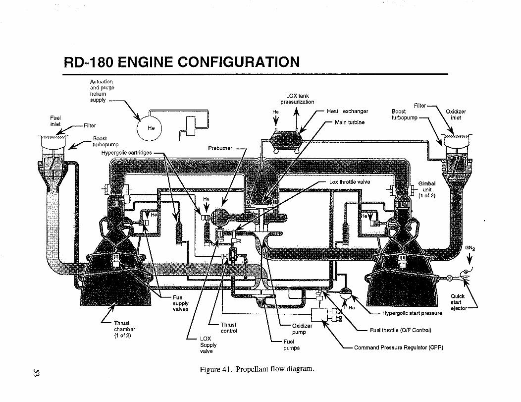
RD-180 ENGINE CONFIGURATION
Actuationand purgeheliumsupply
Fuel !_inl_.__ Filter
Boost
_-" turbopump
Hypergolic cartridges
He
I ii::i)iiiiii
_-:,_iiiil)ii::_i
_':";:":;_
Prebumer
LOX tank
pressurization
Heat exchanger
Main turbine
Lox throttle valve
Boostturbopump
Glmbalunit
(1 of 2)
Oxidizerinlet
GN2
Fuelsupplyvalves
Thrust Thrust Oxidizer
chamber control pump(1 of 2) LOX
FuelSupplyvalve pumps
Hypergolic start pressure
Fuel throttle (O/F Control)
Command Pressure Regulator (CPR)
Quickstart
ejector
Figure 41. Propellant flow diagram.
HI. FABRICATION, INTEGRATION, AND VERIFICATION
A. Manufacturing and Assembly
This booster is to be designed, built and ready to launch in 40 months from authority to proceed
(ATP). Three manufacturing options were investigated:
(1) Procure all major assemblies and assemble only the booster. This approach would procure
the forward and aft skirts, intertank structures, fuel and oxidizer tanks, thrust adapters,
feedlines, etc.
(2) Procure the major subassemblies and assemble into major assemblies. This requires pro-curement of fuel and oxidizer tank barrel sections and domes, the forward and aft skirt sec-
tions to be assembled, the intertank sections, thrust adapters, feedlines, etc. This approach
requires large weld fixtures to assemble the tanks.
(3) Procure the piece parts and perform most major subassembly and assembly work in-house.
This approach procures the tank dome gores, barrel panels, finished rings, sheet metal parts
for the skirts and intertank, as well as the thrust adapters, feedlines, etc. This option uses the
similar technique to assemble as the present shuttle ET.
To meet the schedule with minimum risk, it was decided to use option 3. It is estimated that80,000 to 100,000 ft z of floor space would be required for manufacturing and checkout. Sufficient floor
space is available at MSFC, but is presently assigned to other projects, and, therefore, not readilyavailable.
The major hard tooling required is two quarter-dome trim, alignment, and weld fixtures; one
half-dome trim and weld fixture; one full-dome trim and weld fixture; one trim, alignment, and weld fix-
ture for welding the tank barrel sections' skin sections; one trim, alignment, and weld fixture for joining
the barrel sections together; the intermediate rings; and the tank domes. An additional fixture is required
for manufacturing the skin and stringer intertank and skirt assemblies. These fixtures do not have to be
in the same building, but should be in proximity for easy transport.
A hydrostatic test facility may be required for leak testing each tank prior to stage assembly. A
candidate location is building 4707. This would be a suitable location to perform internal cleaning ofeach tank. The final assembly requires a high-bay area with sufficient floor space and overhead cranes to
assemble the major subassemblies into the finished product.
An exercise was conducted to locate the booster manufacturing and assembly in the same loca-
tion. The candidate building selected was building 4705. The tank dome trim and weld fixtures could belocated along the east side of the low-bay area. The domes could be completed, including the access
holes and the propellant outlet(s). The barrel section trim and weld and tank assembly fixtures could be
located in the east high bay. As each tank is completed, it is transferred to building 4707 for cleaning
and leak testing. When testing is complete, the tanks are transferred back to the west high-bay aisle of
building 4705 for assembly with the interstage, intertank, and thrust structure/boattail.
The propellant feedlines, valves, regulators, pressurization tubing, and other propulsion system
hardware would be purchased from available vendors. Installation brackets and fixtures would be sup-
plied by MSFC. The RD-180 engine system would be purchased from Pratt and Whitney, certified and
ready to install.
54

Thechecked-outavionicsboxeswill besuppliedfor assemblyfrom theAstrionicsLaboratoryforinstallationandsystemverification.It is assumedthateachcomponentwill bedeliveredindividuallyverified andreadyfor installation.Thebracketsandwiring harnesseswill bemanufacturedandinstalledin building 4705.
Theabovefast-trackapproachwill requireconsiderablecapitalinvestmentfor thehardtoolingfixtures.Therequiredhardtoolingwouldbepurchasedthroughstreamlineddesignandfabricatepro-curementbid packages.Any testfixturesrequiredwouldbedesignedandbuilt in-houseandtheshopoverloadwould beprocuredby abasicorderingagreement(BOA). For aprojectof this size,andtheleadtimesavailable,theprocurementprocesswouldrequirestreamlining.Theshopwouldhaveto havedirectpurchaseorderauthority.
It is plannedto turn themanufacturing(toolingandlabor)of thisboosteroverto industryafterthefifth or seventhvehicle.Thesenumbersaresomewhatarbitrary,but shouldbereasonablein light oftheprojectedflight rateandthetransitiontime.
1. Pr0d0cti0n Enhancements. There are opportunities for manufacturing improvement as this
stage is transitioned to commercial manufacturing. The most obvious is the spin forming of the tank
domes. The methodology has been developed for smaller diameters and could be economically adapted
to this size if the production rate warrants. Extrusion of the tank barrel sidewall sections to near net
shape would eliminate some of the intermediate welding to obtain the required lengths, but at a weight
cost because tapered extrusions of this type are not yet developed.
B. Test Requirements
The design concept of the 20k booster was to minimize DDT&E and postmanufacturing testing.
The previous design and manufacturing sections supply supporting data.
1. Structural Testing. Preliminary analyses show that the booster can be designed with a struc-
tural safety factor of 2 and meet the payload requirement. If this holds true for the final design, a static
structural load test will not be required. However, if the final booster design cannot be accomplished
with the safety factor of 2, a static structural test may be required. Static structural testing criteria will beestablished at that time.
A modal survey test normally performed on structures such as this is not required. Presently, the
design personnel are confident that the dynamic characteristics of the booster can be analytically pre-
dicted. If it is decided later tha! the modal survey test must be performed, the test requirements will be
established at that time. There is a possibility that this type test could be performed in conjunction with
the following propulsion test setup.
2. Propulsion System Test Requirements. Main propulsion system (MPS) and engine system testrequirements for this 20k booster are based on the requirement that the RD-180 engine will be delivered
ready to fly. (This implies no separate in-house engine development, verification, certification, or cali-
bration testing required.) Demonstrated reliability is not considered to be a test requirement. It is pro-posed to use the first manufactured booster stage to perform the propulsion system testing. Following
testing, this stage would be refl_rbished as a flight stage, possibly as a development flight instrumented
(DFI) vehicle.
55
MPS andenginesystemtestrequirementsare:
(a) Six coldflow testsusinginitial feedsystemandsimulatedtankbottomfor thepurposeoff
• Evaluating lox conditioning• Developing fill and drain procedures
• Initial contingency procedure planning.
(b) Six terminal drain tests utilizing initial tanks (or tank bottoms) and feedline (engine system
not required) for the purpose of:
• Developing shutdown sequence
• Verifying depletion sensor locations.
(c) Twelve MPS tests (hot firing required) of initial tank set and feed system set (engine system
required) for the purpose of"
• Tank fill and drain verification
• Propulsion start/shutdown sequencing
• Contingency procedures planning
• System verification, and propulsion system qualification.
Assembly, test preparation, and servicing procedures will be evaluated during all of the above tests. Sub-
system level test requirements (i.e., those other than MPS/engine system) are TBD.
3. Alternate Propulsion System Testing. An alternate approach to the propulsion system testing
is to verify the piping/valve system on the MSFC cold flow facility and to perform the remaining tests
on the launch pad, including a short duration captive firing. The impact of this option on the launch pad
design would have to be traded against cost, schedule, and risk of the approach in section III.B.2. The
final approach is TBD based on final requirements, maturity, and certification of the delivered engine.
4. Avionics Testing. The avionics testing will be basically booster stand-alone testing using an
upper stage-supplied functional simulator emulating the upper stage and payload fairing and any electri-
cal pass-throughs requiring continunity verifying, at least one launch pad simulator, and other govern-ment-supplied equipment (GSE) as required. Actuators and valves are tested as required. A similar
booster/ground interface simulator would be supplied to the upper stage contractor. This method will
allow both stages to be tested at their respective factories and to be ready for final mating and integrationat the launch site.
C. Facilities Requirements
MSFC has facilities that are potentially available to manufacture, test, and verify the 20k booster.
Candidates are the hydrostatic test tower in building 4707; the shop floor and electrical engineering shop
in building 4705; the first floor shop area in building 4655; the first floor in building 4754; and a sectionof building 4650. Test and storage facilities will have to be defined as requirements evolve.
Depending on the final definition of the propulsion system test requirements, a vertical test stand
with sufficient structural capability to hold and service the booster may be required. Possible candidates
are the advanced engine test facility or the hydrocarbon engine test facility located in the west test areaof MSFC.
56
IV. OPERATIONS REQUIREMENTS
A. Assembly and Integration
The integrate-transfer-launch process will be implemented for this system. The individual stages
will be delivered completed, including testing performed at the manufacturing plants, to the integration
facility at the launch site. Stages should have inert pressurization in order to keep them from breathingduring the temperature swings. The stages will arrive with the avionics in a safe mode. The individual
stages and interstage will be assembled on the launch transporter. This transporter will provide all pro-
pellant, electrical, air conditioning, and ground service connections between the launch pad and thevehicle. Each individual stages' interfaces have been verified at its factory using standard simulators.
The end-to-end vehicle avionics test and the verification of the payload service pass-through wiring are
the only post integration tests required.
For this vehicle configuration, it will be possible to integrate the Centaur and the payload sepa-
rately from the booster, enclose it within the payload fairing, complete all upper stage/payload verifica-
tions, and then transport this stack to be mated with the booster. This allows parallel operations to occur
and should reduce preflight process time. Once the total vehicle verification is completed, the vehicle
system is ready to transport to the pad for launch. The design goal from rollout to launch is to be lessthan 24 clock hours.
The transporter serves as the vehicle launch platform and service tower. After the transporter is
harddown to the pad, fueling and final prelaunch checkout can be performed. The terminal count, igni-
tion, and ground holddown release will be performed by the prescribed method dictated by the Centaur
requirements in conjunction with the ground system monitoring. Interrupt capabilities from both the
ground and/or payload will be available to analyze/correct sensed anomalies.
An avionics upgrade will allow the onboard avionics to perform the final count, engine ignition,
and lift-off signals. This is not presently part of the standard Centaur flight avionics operation.
B. Flight Operations
The flight will be automously controlled by the Centaur avionics system, including the terminal
stage disposal maneuver. Preflight analyses will be streamlined by the requirement that the vehicle be
able to accommodate payload weight/center-of-gravity, natural frequency combinations within a pre-
described volume as described in the vehicle-to-payload interface control document (ICD). The vehicle
will have a number of standard flight profiles to standard orbits. Special missions will be accommodatedat a TBD extra cost.
V. SYSTEM MANAGEMENT
A. Program Risk Analysis
The primary objective of the risk assessment is to identify risks as early as possible so that work-
around plans may be implemented before the potential risks become "program stoppers." The payloadshroud and upper stage can be purchased from existing vendors who have established data bases with
verified performance parameters, cost projections, and scheduling processes. Large uncertainties do not
exist for these items due to ongoing production capabilities and facilities. Minor uncertainties may be
57
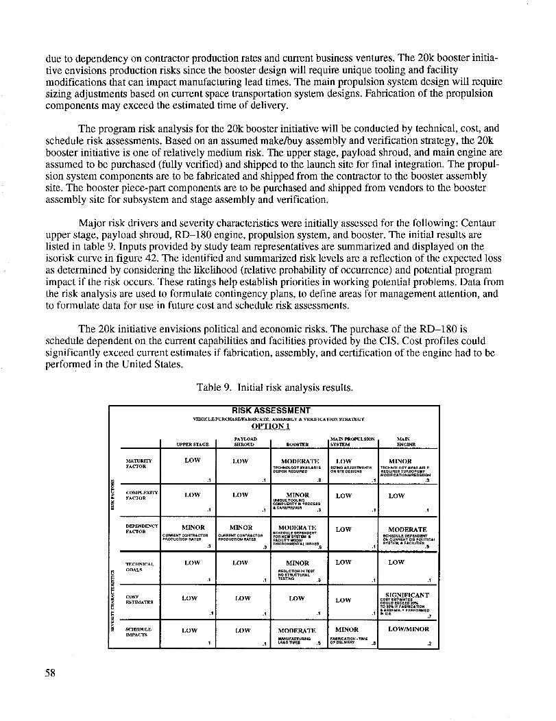
dueto dependencyoncontractorproductionratesandcurrentbusinessventures.The 20kboosterinitia-tive envisionsproductionriskssincetheboosterdesignwill requireuniquetoolingandfacilitymodificationsthatcanimpactmanufacturingleadtimes.Themainpropulsionsystemdesign will require
sizing adjustments based on current space transportation system designs. Fabrication of the propulsion
components may exceed the estimated time of delivery.
The program risk analysis for the 20k booster initiative will be conducted by technical, cost, and
schedule risk assessments. Based on an assumed make/buy assembly and verification strategy, the 20k
booster initiative is one of relatively medium risk. The upper stage, payload shroud, and main engine are
assumed to be purchased (fully verified) and shipped to the launch site for final integration. The propul-sion system components are to be fabricated and shipped from the contractor to the booster assembly
site. The booster piece-part components are to be purchased and shipped from vendors to the booster
assembly site for subsystem and stage assembly and verification.
Major risk drivers and severity characteristics were initially assessed for the following: Centaur
upper stage, payload shroud, RD-180 engine, propulsion system, and booster. The initial results are
listed in table 9. Inputs provided by study team representatives are summarized and displayed on theisorisk curve in figure 42. The identified and summarized risk levels are a reflection of the expected loss
as determined by considering the likelihood (relative probability of occurrence) and potential program
impact if the risk occurs. These ratings help establish priorities in working potential problems. Data from
the risk analysis are used to formulate contingency plans, to define areas for management attention, andto formulate data for use in future cost and schedule risk assessments.
The 20k initiative envisions political and economic risks. The purchase of the RD-180 is
schedule dependent on the current capabilities and facilities provided by the CIS. Cost profiles could
significantly exceed current estimates if fabrication, assembly, and certification of the engine had to be
performed in the United States.
Table 9. Initial risk analysis results.
MATURITY
FACTOR
COMPLEXITY
FACTOR
DEPENDENCY
FACTOR
TECHNICAL
GOALS
COST
ESTIMATES
SCHEDULE
I]V/PACTS
RISK ASSESSMENTVEHICLEPURCHASE/FABRICATE, ASSEMBLY & VERIFICATION STRA'I_GY
UPPERSTAGE
LOW
.1
LOW
.1
MINOR
' CURRENT CONTRACTORPRODUCTION P_TE8
.3
LOW
.I
LOW
.1
LOW
.1
OPTION 1
PAYLOAD
SHROUD
MINOR
CURRENt CONq'RACTORPRODUCTION RATES
.3
LOW
LOW
.1
LOW
.1
BOOSTER
MODERATE
TECHNOLOGY AV_LAB LEDEE_GNREQUIRED
.6
MINORUNIOUETOOLINGCOMPLEXffY IN PROCESS
& CARE/REPAIR ,3
MODERATE8CHEOULE DEPENDENTFORNEW EYSTEM &FACiLiTYMODP.JENViRONMENT&LlEEUF._
.6
MINOR
RffDUCTION;N TESTNO STRUCTURAL
TESTING ,3
MODERATE
MANUFACTURINGLEAD TIME8 .5
MAIN PROPULSION MAIN
SYSTEM ENGINE
LOW
E_ING ACJ USTMENTSON 8TS DESIGNS
.1:
LOW
LOW
LOW
LOW
MINOR
FABPJCA_ON - TIMEOF DELNERY
MINOR
TECHNOLOGY AVAILABLEREQUIRES TURBOPUMPMOOIR CAT_ON8*'REDESlGN
.3
LOW
.1
MODERATE8CHEDU LE DEPENDENTON CURRENT ClE POLfflCAL
SYSTEM, & FACIUTIES .5
LOW
.1 .1
SIGNIFICANTCOST EETIMAT E8COULD EXCEED2O%TO E0%IF FABRICATION&ASSEMBLY PERFORMED
.1 IN U.S..7
LOW/MINOR
.3 .2
58
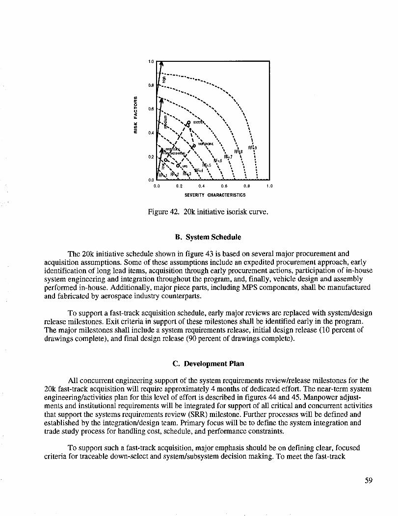
1.0
0.8
0.6
0.4
0.2
0.0
0.0
.. "... ..% I • - MA_nNE • * I
,O_'% /', \ l_-s _." ; 1
0.2 0.4 0.6 0.8
SEVERITY CHARACTERISTICS
Figure 42. 20k initiative isorisk curve.
B. System Schedule
The 20k initiative schedule shown in figure 43 is based on several major procurement and
acquisition assumptions. Some of these assumptions include an expedited procurement approach, early
identification of long lead items, acquisition through early procurement actions, participation of in-house
system engineering and integration throughout the program, and, finally, vehicle design and assembly
performed in-house. Additionally, major piece parts, including MPS components, shall be manufactured
and fabricated by aerospace industry counterparts.
To support a fast-track acquisition schedule, early major reviews are replaced with system/design
release milestones. Exit criteria in support of these milestones shall be identified early in the program.
The major milestones shall include a system requirements release, initial design release (10 percent of
drawings complete), and final design release (90 percent of drawings complete).
C. Development Plan
All concurrent engineering support of the system requirements review/release milestones for the
20k fast-track acquisition will require approximately 4 months of dedicated effort. The near-term system
engineering/activities plan for this level of effort is described in figures 44 and 45. Manpower adjust-
ments and institutional requirements will be integrated for support of all critical and concurrent activities
that support the systems requirements review (SRR) milestone. Further processes will be defined and
established by the integration/design team. Primary focus will be to define the system integration andtrade study process for handling cost, schedule, and performance constraints.
To support such a fast-track acquisition, major emphasis should be on defining clear, focused
criteria for traceable down-select and system/subsystem decision making. To meet the fast-track
59
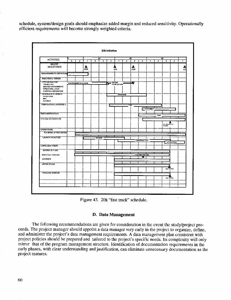
schedule,system/designgoalsshouldemphasizeaddedmarginandreducedsensitivity.Operationallyefficient requirementswill becomestronglyweightedcriteria.
20k Initiative
ACTIVITIES [.3 -" 94 .= ss ss"'"";.........;'"'"'"1'........_........; ........;;'"-'"_'"-'"'_'"'T'"_"........;"........;........._........._........"_.........;.....
MAJOR iM,'ESTO,,,ES i A h i i,, ,,,.
"SRR ,OR i i FOR ,t.C
'_i'_'6;_'_'_'s_';_i ...........................i'........................"....................'-'.........._................................................................'"..........•",_,:v_',_"_,",r,_r_"........i..........}.........................................":'....................i"..........i............................................................................
; : .. = :
•_.%%,,__:..................................._.v_,:o,,_..................................................................................................................................- ' ,,,,..,__,z,,._._ ' 'IqOUCIB3 ENVIRONMIENI"S
STRLICTURAL LOADS
CONIROL & SEPARATION
STRUCTURAL
PAPS
AVIONICS
•",,_,r_,',',_'r._'_,_'...........................................................i.......:.........:.........,_z.........i..........:.........:........i.........i".....................t_ .'_S[:MI3L¥ ' I
•-,'-'_'.t:',,--rt:_- •_'.........................................................................................................................i.........._.........._.........._...................
OPERATIONS: : : : : : : : : : : : : :
...... /,1_14r_" __l_uu_ _ _.......... _......... ";......... ";......... '; ......... 4 ......... _ ......... _........... i.......... i .......... i .......... _......... ,;......... 4 ......... ,$.........
....r_u_,:,'_'_i_m_"............................._................_,_N...........................i-.......i..........i ..........i .........:':..........i .........:':.........:':.........CONSTRL:G_ _N I ;
.................... z.......... s......... .; .......... s......... a ......... _ ......... &......... o.......... z.......... s.......... s.......... s.......... i ......... ._......... ._.........; t9,_5 t'fg_: : : : : : : : : : : : :
: : : : : : : : : : : :
.... ................................:..........:.........-:..........:.........:.........:..........:..........:..........:..........:..........:.............................I l l i l i l
BOOSTER TOOLING TOOLING ON-LINE I:
AVIONICS = ; :" ; ill .." :" 1 "::
..................................... _.......... s......... a .......... s......... a ......... .a......... &......... &.......... i.......... |.......... i.......... ;......... ,i ......... .i ......... ,o.........
i _ _ ; _ -: : .: DB_ TO KSC :
...._'_'_'_""_"_"........._.........._.........._........." ........._,.........T.........i .........................................................................." ........._".........
....................................i..........i..........i..........i.........i.........i.........i.........i..........i..........i..........i..........i..........i.........?.........?.........; :. - ; ..- : .." • . . ..- . ..- • .
Figure 43. 20k "fast track" schedule.
D. Data Management
The following recommendations are given for consideration in the event the study/project pro-ceeds. The project manager should appoint a data manager very early in the project to organize, define,
and administer the project's data management requirements. A data management plan consistent with
project policies should be prepared and tailored to the project's specific needs. Its complexity will only
mirror that of the program management structure. Identification of documentation requirements in the
early phases, with clear understanding and justification, can eliminate unnecessary documentation as theproject matures.
6O
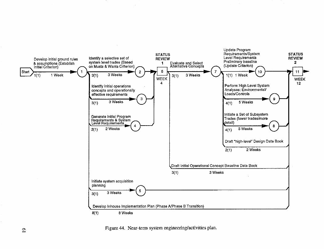
STATUS
Develop initialground rules Identify a selective set of REVIEW& assumptions (Establish system level trades (Based 1
i-_1 nitial C rit eric n) (_'_n Musts & Wants Criteri°,_n)_ i_L----/1(1) 1 Week _ 3(1) 3Weeks ""- _ ""WEEK
Identify initial operationsconcepts and operationally
effective requirements3(1) 3 Weeks
Update ProgramRequirements/SystemLevel Requirements
Evaluate and Select Preliminary baseline
Alternative Concepts,,.._,...=(_(Update Criterion),,.._,..__Q3(1) 3 Weeks _ ] 1(1) 1 Week
I Perform High Level SystemAnalyses: EnvironmentaVLoads/Controls
Generate initial Program.Requir..emen.ts& System_
_Level Hequ=remenTs_ ( A2 Weeks2(1)
4
,4(1) 5 Weeks
Initiate a Set of SubsystemTrades (fewer trades/more
_detail)4(1 ) 5 Weeks
Draft "high-level" Design Data Book
2(1) 2 Weeks
_Draft Initial Operational Concept Baseline Data Book
3(1 ) 3 Weeks
Initiate system acquisition
i planning
3(1) 3 Weeks _ Q
Develop Inhouse Implementation Plan (Phase A/Phase B Transition)
8(1) 8 Weeks
STATUSREVIEW
2
Figure 44. Near-term system engineering/activities plan.

o_
STATUSREVIEW
2 TIM Update the InitialOperations Concept
r_Update Design Data B°°k_(___i_Ft_' 2(1)D°cumentL._._J" 2(1) 2 weeks 2 Weeks
WEEK14
Update Feasible System• Concept Data Book ,,,..._(" _9 "_
k.Z,y2(1) 2 weeks
Draft a Program Plan
2(1) 2 weeks
Update the Program/SystemRequirements Document for
Baseline Approval _
2(1) 2 Weeks
Draft an Initial System Level WBS(4th Level- Scope, Tasks, Manpower
Schedule,Cost) _2(1) 2 Weeks
Draft/Tailor an initial
specification list _
2(1) 2 Weeks ,,,....J
Draft an Initial
Documentation Tree._ _
1(1) 1 Week
Draft Preliminary Tailored Spec
Requirements List
2(1 ) 2 Weeks
Establish PreliminaryInterface Working Groups
& Identify Necessary ICD's2(1) 2 Weeks
SYSTEMREQUIREMENTS
REVIEW (SRR)
WEEK18
Figure 45. Near-term system engineering/activities plan.

To meetthedevelopmenttimeof 40monthsfrom ATP to flight vehicle"out-the-door,"concur-rentengineeringis mandatory.Thiswill requirethebaselining of designs, drawings, specifications, etc.,to be streamlined. Real-time changes will have to be negotiated and a documentation "czar" will have to
be named to control and expedite changes. Documentation will have to be justified as required, not "nice
to have." Applicable specifications will have to be placed on drawings rather than referencing a docu-ment.
Definition of procured and in-house developed items will be crucial to the identification of pro-
ject documentation and, therefore, should take place early in the project.
VI. FUTURE TRADES
Individual teams were tasked to define trade studies they recognized for a follow-on effort or
execution of this project. They are listed as submitted:
A. Structures Trades
lO0-in long common dry bay elements
Change the 60-in long common elements to 100-in long common elements.
Composite dry bays
Trade the aluminum skin/stringer construction method with composite face sheet-aluminum
honeycomb core construction. The composite parts could be made on the tape laying machine in
building 4707. Autoclave versus oven cure is an additional option.
Isogrid construction cost versus skin�stringer cost
The cost of isogrid/orthogrid needs to be determined for a decision on manufacturing method ofthe tanks.
Semimonocoque tanks�integral slosh baffles
The pressure in the tanks significantly stabilizes the structure. It may be possible to have a skinwith rings only. Rings would help reduce slosh problems and could be increased to act as theslosh baffles.
Launch facilities
The current configuration requires the engine to be extracted through a hold in the pad. Depend-
ing on vehicle drift and acceleration, the holddown mechanism may need to retract to give
acceptable clearance (figs. 2 and 6).
Separation systems
A linear-shaped charge separation needs to be compared with a "super-zip" type separation. The
separation hardware needs to be sized.
Booster/payload shroud interface
This interface needs greater definition and design.
63
Boattail
The boattail of the shroud needs greater definition and design.
Thrust structure
The conical thrust structure needs more design. The RD-180 may provide whatever thrust struc-
ture is needed, so this part might be removed.
Engine aerocover
The aerodynamic, heating, and vibration loads on the engine aerocover require definition so that
this structure can be designed.
Slosh-bafflesThe structural design and damping requirements of the slosh-baffles needs refinement.
Fins/conical aft structure
The need for fins must be determined, and the possibility of using a conical aft structure instead
of fins needs to be traded (fig. 7). Base drag may be too high to use a conical structure. If fins are
required, the configuration (number and size) must be determined.
Tank size
The current tanks are slightly oversized to allow for variations during this study phase. Theyexact size will be determined.
Buildup�shutdown and lift-off loads
The buildup/shutdown and lift-off loads need to be incorporated into the mass properties.
L02 sump for reduced intertank length
The difficulties of using a sump feed system instead of the current configuration need to betraded with the required length of the intertank (and the common dry bay elements).
Helium tanks
The location, volume, and mounting of the pressurant tanks need to be determined.
Avionics mounting
The avionics locations need to be verified, a mounting method defined, and cable routingdefined.
Feed line support
The feedline support and protection methods need to be defined.
Systems tunnel
The systems tunnel size and mounting method need to be determined.
Dome manhole
The access holes in tank domes need to be sized and designed.
64
B. Stress Trades
The aft skirt needs to be resized to include the fin loads.
The interface between the aft skirt and the pad holddown structure needs further trade studies.
The rings in the dry bays at the 60-in cylinder joints need further analyses.
A trade for low height versus standard height bulkheads should be performed.
C. Aerodynamic Trades
Aerodynamic trade studies would involve the nose configuration, the length and diameter of the
various vehicle component sections, and methods of improving the static stability of the vehicle. Per-
formance may be enhanced by developing a new payload fairing which would incorporate tangent ogive
geometry. Aerodynamic analysis of any proposed configuration modifications such as transitions for
diameter changes would be required. Static stability can be improved in a variety of ways, such as alter-ing the nose cone/payload fairing, adding fins, or flaring the aft skirt. Wind tunnel testing would be
desired to support the development of an accurate design data base.
D. Propulsion System Trades
Additional analyses are required to define the propulsion system test requirements that must be
accomplished prior to first flight and the facilities and schedule to accomplish the testing. It is assumed
that fill and drain, terminal drain, and hot-fire tests are requirements. The number of fill and drain tests
will require further definition of the loading and on-pad drain sequences and procedures, for example.The number Of terminal drain tests will depend on the engine requirements during shutdown, including
the impact of fuel or oxidizer starvation on the engine. The number of hot-fire tests will also depend on
the test requirements, which are yet to be defined.
Further work is also required to understand the RD-180 servicing, pre-launch checkout, and
launch commit criteria as well as the checkout procedures, loading procedures, and launch commit cri-
teria for the rest of the propulsion system.
Better understanding of the RD-180 operations may result in significant changes in the propul-
sion system. One example would be the availability of only one heat exchanger for pressurizationhelium.
Trade studies on the propellant feed line diameters are required. The trade should include costand schedule effects as well as performance. The fuel feedline configuration will need to be reexamined
once the RD-180 interface requirements and aft compartment clearances are defined. Purge require-
ments for the forward, intertank, and aft compartments need to be defined.
E. Propulsion Testing Trades
Some subsystem level test objectives can be met during main propulsion system/engine system
level tests. These are TBD pending identification of subsystem level test requirements.
65
F. Performance Trades
Trade studies could include variations on the engine types and capabilities for both the first and
second stages. The effects of various payload fairings could be investigated. For this study, only one
LEO and a single GTO mission were considered. A variety of missions, such as other geotransfer orbits
and GEO's, should be investigated.
G. Avionics Trades
Avionics trades include upgrading the guidance and navigation functions to include global
positioning system (GPS) receivers for positioning, developing vehicle health monitoring/management
into the overall design, efficient electrical power generation and switching systems, and defining the
number of strings required to meet the TBD reliability.
H. Design and Manufacturing Trades
High performance work team(s) will be established to evolve the most efficient design-for-manu-
facture concept that would meet the requirements and be cost competitive in production.
VII. ENVIRONMENTAL REQUIREMENTS
A. Environmental Assessment/Environmental Impact Statement
The Code of Federal Regulations (14 CFR Part 1216.305) states explicitly than an environmental
assessment (EA) or environmental impact statement (EIS) is required for any proposed action by NASAto develop and operate new launch vehicles that may have an impact upon the quality of the environ-
ment. This requirement is detailed in accordance with NASA Handbook (NHB) 8800.11, which deals
with implementing the provisions of the National Environmental Policy Act (NEPA) of 1969.
An EA is required when the need for an EIS is not known. The purpose of the EA is to determine
the necessity for the EIS if significant impacts are found, or vice versa if not. However, as specified in
NHB 8800.11, the release of rocket exhaust gases into the atmosphere is one of three categories of
NASA actions that has been recognized since 1970 as requiring an EIS. Also specified is that all
environmental analyses should be directed toward early planning and execution of the EIS from the out-
set of the project, that the notice of intent to proceed with the EIS be published, and the remainder of the
EIS process be initiated immediately.
B. Clean Air Act Amendments of 1990
The clean air act amendments (CAAA's) of 1990 requires all states to submit an operating permit
plan which upon approval by the U.S. Environmental Protection Agency (EPA) will allow and require
each State to permit and monitor air emission sources. Each facility (company, business, military base,
federal facility, etc.) will then be required to submit an operating permit application. This application is
expected to require inclusion of all Center-wide foreseeable operating scenarios during the 5-year permit
timeframe for major sources, and plants subject to the national emission sources hazardous air pollutants
criteria. The operating permit also contains a fee payment rate based on pollutant quantities.
66
The 20kboosterprogramwouldrequireinclusionin theMSFCoperatingpermit application.EPA-approvedair modelingof engineemissionsandclouddispersionpatternsduringthevaryingweatherconditionswouldbe required.Failureto includetheprogramin theoperatingpermit applicationwith sufficient testingscenarioflexibility couldhamperprogramprogress.
C. Clean Water Act National Pollution Discharge Elimination System Permit Application
The existing National Pollution Discharge Elimination System permit will require modification
to accommodate the changing discharges as required in the Clean Water Act.
D. Deluge Pond Remediation
The two candidate test stands for the proposed 20k booster testing at MSFC that were discussed
in section III.B are the F-1 stand, building 4696, in the west test area and the Saturn 1-C stand, building
4572, in the east test area. Both facilities have associated deluge or holding ponds that have been classi-fied as solid waste management units by the EPA.
Investigation of both sites by MSFC is planned for FY94 to determine the extent of the soil and
ground water contamination. Based on the results of these examinations, remediation activities would
then be planned and implemented. Expediting this process would be possible pending EPA and Alabama
Department of Environmental Management regulatory approval.
E. Asbestos Abatement
The two test stands mentioned in section VII.D will have some asbestos abatement. The abate-
ment and disposal will be performed in accordance with the Toxic Substances Control Act (TSCA) and
the Occupational Safety and Health Administration (OSHA). Any work that can be performed withoutdisturbing the asbestos is allowable.
F. Lead Paint Refurbishment
The two test stands mentioned in section VII.D most probably were primed and painted with
chromium- and lead-based coating. Any modifications to either stand that involves abrasive blasting,
welding, or other coating disruption would require adherence with Resource Conservation and RecoveryAct (RCRA) hazardous waste regulations and occupational health and safety regulations for personnel
protection.
G. Rocket Propellant Handling
The use of RP in engine testing operations would require modifications to the Center's spill pre-
vention control and countermeasures plan and adequate spill containment structures around the filled
booster (all locations). If any residue fuel was left in any part of the booster after testing, considerations
would be required to minimize any leaks and for the containment of any leakage during transportation tothe launch site.
67

H. The Resource Conservation and Recovery Act
The RCRA regulates the accumulation, packaging, storage, and disposal of hazardous wastes.
For the 20k booster project, it is expected that some hardware will require cleaning or the verification of
cleanliness level prior to assembly and possibly will generate some hazardous waste as a result of testing
operations. MSFC currently retains a contractor to manage this task, and their system is sufficiently
flexible to be able to handle the expected increases in volume and accumulation sites.
VHI. GROWTH PATH OPTIONS
An exercise was performed to define the potential growth of this concept to 65k lb of payload in
LEO. Table 10 summarizes the results of growth path steps. The first step is to replace the Centaur upper
stage with one of increased performance. The stage selected is from an earlier 20k study. The CIS D-57
LO2/LH2 engine was substituted onto the scalable upper Stage and the propellant split between stages
optimized. This produced approximately 27k to LEO.
The RD-170 was substituted for the RD-180, and the booster propellant was increased while
using the Centaur as the upper stage. This configuration provided approximately 40k to LEO.
This booster was combined with the D-57-powered upper stage, and the propellant split was
reoptimized using the stages' scaling equations. This results in performance of 52k to LEO. The final
attempt at growth was to take the above configuration and supplement the booster with two Thiokol
GT-120 solid boosters. This combination yielded 67k in LEO.
IX. CONCLUSIONS AND RECOMMENDATIONS
This exercise shows that a launch vehicle system could be put on-line via a fast-track concept in
a relatively short time, at a reasonable cost. The resulting baseline vehicle is probably not the optimum
for the long haul and, if time permitted, a structured development approach should be undertaken.
If a crash program is not required, it is imperative that the end point of the payload weight and
dimensions growth options be part of the basic requirements. A binding decision must be made up frontthat when the system is operational and the maximum performance envelope defined, the system will not
be stretched to the extreme capability, as today's systems are, which require much preflight analyses to
verify they will fly. This allows the design/manufacturing/operations infrastructure to be traded and
developed as the most overall efficient concept for the country.
The design must include the inserting of emerging technologies as completed which will improve
the product, not just be nice-to-have. High-performance work teams will be required to perform these
analyses and develop the correct scenario. A point in the program must be defined where the vehicle is
operational and the design engineering staff can be dismissed from day-to-day activities.
As the engineering design of the booster is completed, the design team should initiate the new
upper stage and payload fairing design. This sequential approach will allow a reasonable funding profile
and also allow commercial developers participation availability in lieu of total Government funding.
Further studies would develop and refine the requirements and optional attainment methods.
68
Table 10. Growth options performance results.
Engine Types
Flight ParametersMaximum Dynamic PressureMinimum Engine ThrottleMaximum Acceleration
Total Weight at Lift-off
Engine DataRD-180
Thrust
Isp
RD-170Thrust
Isp
RL-10A-4 (2)Thrust, total
Isp
D-57Thrust
Isp
SolidsCastor GT-120
Gross Lift-off Weight
Booster
PropellantStage Weight
Solids
PropellantJettison Wight
Upper StagePropellantStage Weight
Shroud Weight
Margin
Net Payload
B_eline I9-57 Stage Centaur Stage I)-57 Stage
RD-180 RD-180 RD-170 RD-170Centaur D-57 Centaur D-57
D-57 Stage
RD-170D-57
2 GT-120's
591 lb/ft 2 557 lb/ft 2 703 b/ft 2 634 lb/ft 2 799 lb/ft 267.97% 93.1% 50.90% 71.10% 77.13%
4.5 g 4.5 g 4.5 g 4.5 g 4.5 g1.200 1.193 1.200 1.200 1.302
945,000 lbf 945,000 lbf N/A N/A N/A337 s 337 s N/A N/A N/A
N/A N/A 1,776,892 lbf 1,776,892 lbf 1,776,892 lbfN/A N/A 336 s 336 s 336 s
41,600 lbf N/A 41,600 lbf N/A N/A448.9 s N/A 448.9 s N/A N/A
N/A 83,000 lbf N/A 83,000 lbf 83,000 lbfN/A 456 s N/A 456 s 456 s
N/A N/A N/A N/A 2
731,052 lb 726,842 kb 1,358,148 lb 1,358,423 lb 1,582,889 lb
588,312 lb 531,107 lb 1,158,153 lb 1,078,680 lb 1,154,870 lb55,739 lb 49,295 lb 94,082 lb 89,987 lb 95,188 lb
N/A N/A N/A N/A 216,039 lbN/A N/A N/A N/A 17,418 lb
45,727 lb 94,476 lb 45,727 lb 111,175 lb 114,004 lb7,388 lb 11,831 lb 7,388 lb 12,285 lb 12,362 lb
9,200 lb 9,200 lb 9,200 lb 9,200 lb 9,200 lb
4,000 lb 4,000 lb 4,054 lb 5,282 lb 6,709 lb
20,688 lb 26,934 lb 40,544 lb 52,518 lb 67,090 lb
69
APPENDIX
Team Members
The following lists the lead members of the study team and
Name: Area
R. Toelle Lead
A. Frost Aero
A. Phillips Loads/Str
J. Brunty LoadsD. McGhee Loads
J. Finckenor Str Design/layouts
D. Brolliar Str AnalysisJ. Lee RD-180 Data
J. Redus Prop Sys Design
H. Pratt Prop Test Req'sM. Harris Avionics
H. Garrett Avionics
D. McCann Manufacturing
J. Brumley Manufacturing
K. Welzyn Control AnalysisD. Mercier Performance
T. Schmitt Performance
B. Brothers Mass Prop'sR. Wilbanks Str Test
B. Sutherland Specs/Req's/DRD's
D. Havrisik Sys Req's/Risk Assmt
J. Wyckoff Facilities Planning
N. Ogozalek EnvironmentalR. Allen Cost
their area of responsibility.
Org Phone: 544-EE85 0186
ED35 1575PD22 0504
ED22 1489
ED22 1500
ED52 7041
ED24 7199
EE83 4951
EP21 7051
EP15 7069
EB43 3790
EB21 3431
EH51 1018
EH52 1025
ED13 1731PD33 0541
PD33 0542
PD24 0519
ED72 4147
EL32 6552
EE85 6721
AB 14 7922
AB 10 8933
HA31 0117
70
APPROVAL
A 20K PAYLOAD LAUNCH VEHICLE FAST TRACK DEVELOPMENT CONCEPT
USING AN RD-180 ENGINE AND A CENTAUR UPPER STAGE
By R. Toelle
The information in this report has been reviewed for technical content. Review of any informa-
tion concerning Department of Defense or nuclear energy activities or programs has been made by the
MSFC Security Classification Officer. This report, in its entirety, has been determined to be unclassified.
QI_." MCMILLION C
Director, Program Development
71
Form Approved
REPORT DOCUMENTATION PAGE OMaNo.OZO,_-OlSS
PUOliCreDortlng burden for this collection of information isestimated to average 1 hour per resDonse,mOuding the time for reviewing instructions,searchingexisting data sources,gathering and maintaining the data needed, and completing and reviewing the collection of information, Send comments regarding this burden estimate or any other aspect of thiscollectionof information, including suggestionsfor reducingthis burden, to Washington HeadQuartersServices.Directorate for Information ODerationsand Reports, 1215 JeffersonOavusHighway, Suite 1204, Arlington, VA 22202-4302, and to the Office of Management and Budget, Paperwork ReductionProject(0704-0188),Washington, DC 20503.
1. AGENCY USE ONLY (Leave blank) 2. REPORT DATE 3. REPORT TYPE AND DATES COVERED
January 1995 Technical Memorandum4. TITLE AND SUBTITLE 5. FUNDING NUMBERS
A 20k Payload Launch Vehicle Fast Track Development
Concept Using an RD-180 Engine and a Centaur Upper Stage
6. AUTHOR(S)
Compiled by Ronald Toelle
7. PERFORMINGORGANIZATIONNAME(S)AND ADDRESS(ES)George C. Marshall Space Flight Center
Marshall Space Flight Center, Alabama 35812
9. SPONSORING/MONITORINGAGENCYNAME(S)AND ADDRESS(ES)
National Aeronautics and Space Administration
Washington, DC 20546
8. PERFORMING ORGANIZATIONREPORT NUMBER
10. SPONSORING / MONITORINGAGENCY REPORT NUMBER
NASA TM-I08475
11. SUPPLEMENTARY NOTES
Prepared by Space Transportation and Exploration Office.
12a. DISTRIBUTION/AVAILABILITYSTATEMENT
Unclassified--Unlimited
12b. DISTRIBUTION CODE
13. ABSTRACT (Maximum 200words)
A launch vehicle concept to deliver 20,000 lb of payload to a 100-nmi orbit has been defined.
A new liquid oxygen/kerosene booster powered by an RD-180 engine was designed while using a
slightly modified Centaur upper stage. The design, development, and test program met the imposed
40-mo schedule by elimination of major structural testing by increased factors of safety and
concurrent engineering concepts. A growth path to attain 65,000 Ib of payload is developed.
14. SUBJECTTERMS
20k payload, fast-track development, concurrent engineering
17. SECURITY CLASSIFICATION
OF REPORT
Unclassified
18. 19. SECURITY CLASSIFICATIONOF ABSTRACT
Unclassified
"_'O.S. GOVERNMENT PRINTING OFFICE-1994-633-109/20002
SECURITY CLASSIFICATIONOF THIS PAGE
Unclassified
15. NUMBER OF PAGES
79
16, PRICE CODE
I_TS20. LIMITATION OF ABSTRACT
Unlimited
NSN 7540-01-280-5500 Standard Form 298 (Rev 2-89)