a 3d image processing system with shape editing capabilities
TRANSCRIPT
A 3D image processing system with shape editing capabilities: Volume Extractor Ver. 3.0
i-Plants Systems Ltd.
〒020-0173 Iwate-ken Takizawa-mura Sugo152-89 Iwate Prefectural University Regional Cooperation & Research Center,
Advanced Visualization Laboratory (Research Room D) Tel: 019-694-3103 E-mail: [email protected]
1. Introduction Volume Extractor (VE) is a practical 3D image processing software which was researched and
developed at Iwate Prefectural University, Japan. The development of VE was initiated in 1998, and
Ver. 3.0 is presently available for use. VE Ver. 1.0 and 2.0 specialized in the processing and
visualization of 3D images[1]. A 3D printer was installed at the university in 2005, and the demand
for rapid prototyping (RP) triggered the development of specialized software (SMESH Ver. 1.0),
which is capable of editing iso-surface shape data generated from medical images (e.g., bones,
internal organs, and muscles)[2]. Generally, isographic data generated from medical images contains
imperfections (infinitesimal holes, surface inversions, etc.) due to the presence of unnecessary
shapes and noise, and it necessary to remove these imperfections in order to generate output using a
3D printer or a rapid prototyping device. The primary function of SMESH Ver. 1.0 is reading the
iso-surface data generated from a 3D image, then editing it by removing gaps, correcting the
direction of surfaces, deleting garbage, and so on and eventually creating an STL file which can be
used with 3D printers and rapid prototyping devices. Many actual models have been prepared using
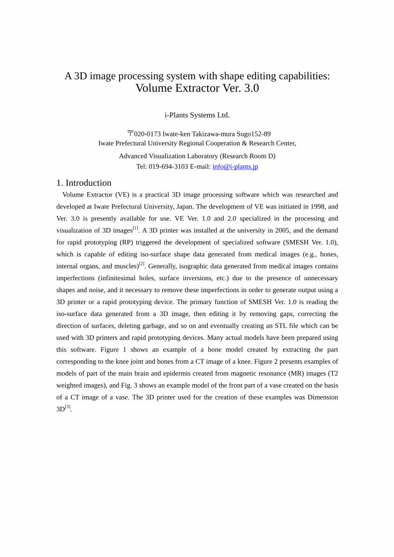
this software. Figure 1 shows an example of a bone model created by extracting the part
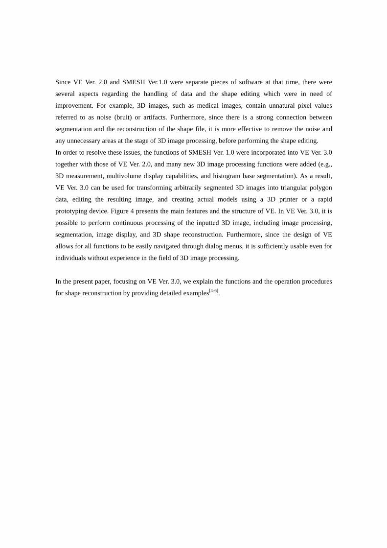
corresponding to the knee joint and bones from a CT image of a knee. Figure 2 presents examples of
models of part of the main brain and epidermis created from magnetic resonance (MR) images (T2
weighted images), and Fig. 3 shows an example model of the front part of a vase created on the basis
of a CT image of a vase. The 3D printer used for the creation of these examples was Dimension
3D[3].
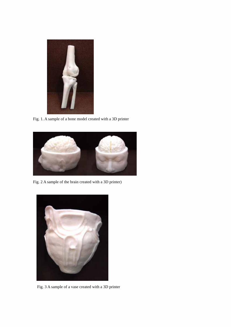
Fig. 1. A sample of a bone model created with a 3D printer
Fig. 2 A sample of the brain created with a 3D printer)
Fig. 3 A sample of a vase created with a 3D printer
Since VE Ver. 2.0 and SMESH Ver.1.0 were separate pieces of software at that time, there were
several aspects regarding the handling of data and the shape editing which were in need of
improvement. For example, 3D images, such as medical images, contain unnatural pixel values
referred to as noise (bruit) or artifacts. Furthermore, since there is a strong connection between
segmentation and the reconstruction of the shape file, it is more effective to remove the noise and
any unnecessary areas at the stage of 3D image processing, before performing the shape editing.
In order to resolve these issues, the functions of SMESH Ver. 1.0 were incorporated into VE Ver. 3.0
together with those of VE Ver. 2.0, and many new 3D image processing functions were added (e.g.,
3D measurement, multivolume display capabilities, and histogram base segmentation). As a result,
VE Ver. 3.0 can be used for transforming arbitrarily segmented 3D images into triangular polygon
data, editing the resulting image, and creating actual models using a 3D printer or a rapid
prototyping device. Figure 4 presents the main features and the structure of VE. In VE Ver. 3.0, it is
possible to perform continuous processing of the inputted 3D image, including image processing,
segmentation, image display, and 3D shape reconstruction. Furthermore, since the design of VE
allows for all functions to be easily navigated through dialog menus, it is sufficiently usable even for
individuals without experience in the field of 3D image processing.
In the present paper, focusing on VE Ver. 3.0, we explain the functions and the operation procedures
for shape reconstruction by providing detailed examples[4-6].
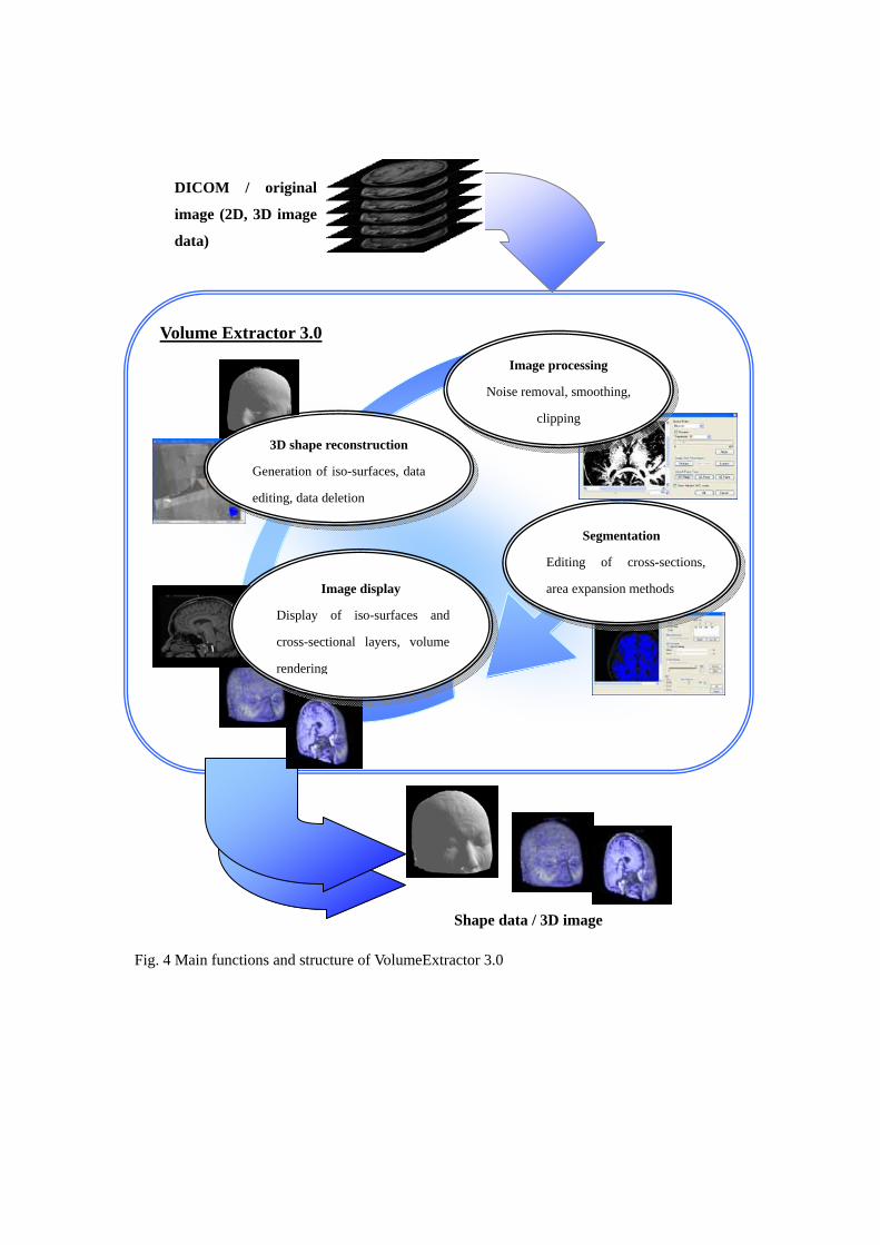
Volume Extractor 3.0
Fig. 4 Main functions and structure of VolumeExtractor 3.0
Shape data / 3D image
3D shape reconstruction
Generation of iso-surfaces, data
editing, data deletion
Image display
Display of iso-surfaces and
cross-sectional layers, volume
rendering
Segmentation
Editing of cross-sections,
area expansion methods
Image processing
Noise removal, smoothing,
clipping
DICOM / original
image (2D, 3D image
data)
2. Overview of the functions VE focuses primarily on the processing of medical imaging data, and offers the following set of
functions [4, 6].
Inputting DICOM images, such as medical images, and constructing 3D images
Displaying multiple 3D images
Extracting portions of 3D images (segmentation)
Measuring 3D images
Reconstructing and manipulating 3D images
Outputting 3D image data and 3D shape data
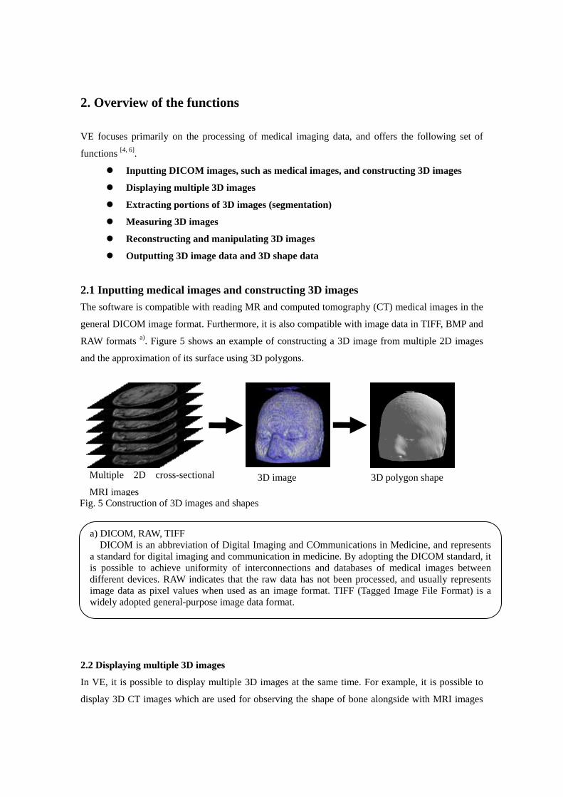
2.1 Inputting medical images and constructing 3D images The software is compatible with reading MR and computed tomography (CT) medical images in the
general DICOM image format. Furthermore, it is also compatible with image data in TIFF, BMP and
RAW formats a). Figure 5 shows an example of constructing a 3D image from multiple 2D images
and the approximation of its surface using 3D polygons.
2.2 Displaying multiple 3D images
In VE, it is possible to display multiple 3D images at the same time. For example, it is possible to
display 3D CT images which are used for observing the shape of bone alongside with MRI images
a) DICOM, RAW, TIFF DICOM is an abbreviation of Digital Imaging and COmmunications in Medicine, and represents
a standard for digital imaging and communication in medicine. By adopting the DICOM standard, it is possible to achieve uniformity of interconnections and databases of medical images between different devices. RAW indicates that the raw data has not been processed, and usually represents image data as pixel values when used as an image format. TIFF (Tagged Image File Format) is a widely adopted general-purpose image data format.
3D image 3D polygon shape Multiple 2D cross-sectional
MRI images Fig. 5 Construction of 3D images and shapes
which are used for observing cartilage and internal organs. The software supports cross-section,
iso-surface, and volume rendering display methods, as well as any combination of the three. The 3D
images are referred to as "volumetric images" or "3D volumetric images", and volume rendering is a
rendering (image generation) technique for the effective display of volumetric images. VE can
perform high-speed display of 3D images by utilizing Graphic Processing Units (GPUs) for the
volume rendering.
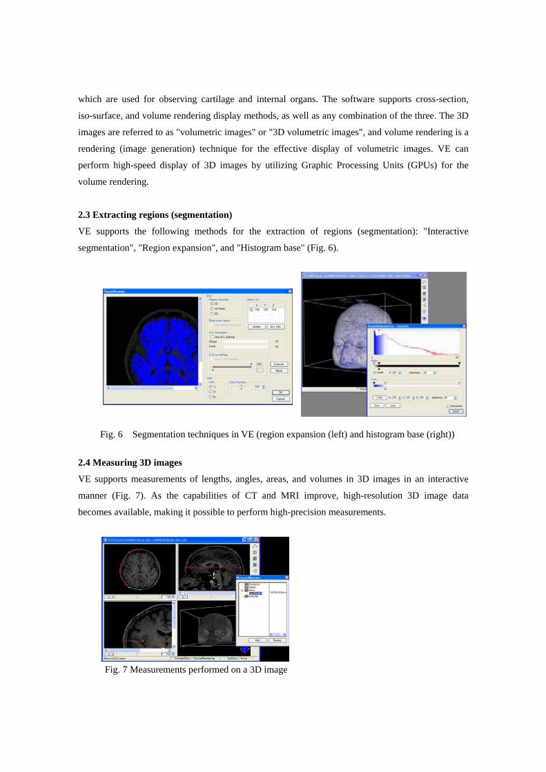
2.3 Extracting regions (segmentation)
VE supports the following methods for the extraction of regions (segmentation): "Interactive
segmentation", "Region expansion", and "Histogram base" (Fig. 6).
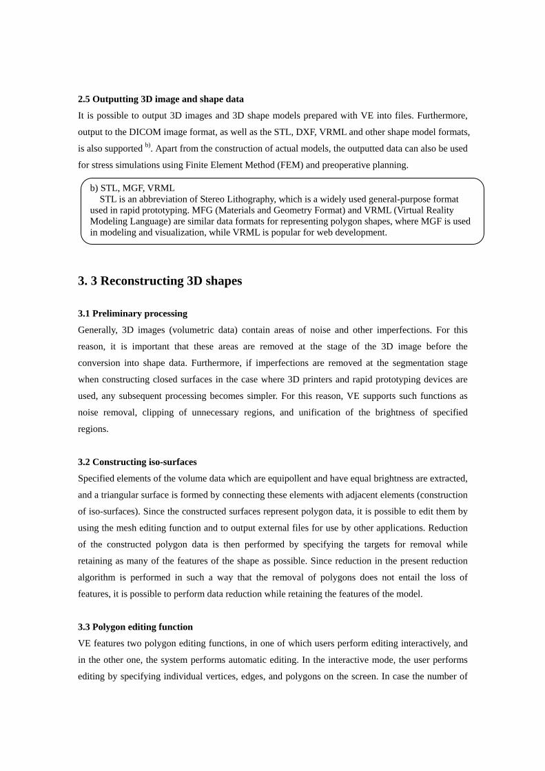
2.4 Measuring 3D images
VE supports measurements of lengths, angles, areas, and volumes in 3D images in an interactive
manner (Fig. 7). As the capabilities of CT and MRI improve, high-resolution 3D image data
becomes available, making it possible to perform high-precision measurements.
Fig. 6 Segmentation techniques in VE (region expansion (left) and histogram base (right))
Fig. 7 Measurements performed on a 3D image
2.5 Outputting 3D image and shape data
It is possible to output 3D images and 3D shape models prepared with VE into files. Furthermore,
output to the DICOM image format, as well as the STL, DXF, VRML and other shape model formats,
is also supported b). Apart from the construction of actual models, the outputted data can also be used
for stress simulations using Finite Element Method (FEM) and preoperative planning.
3. 3 Reconstructing 3D shapes
3.1 Preliminary processing
Generally, 3D images (volumetric data) contain areas of noise and other imperfections. For this
reason, it is important that these areas are removed at the stage of the 3D image before the
conversion into shape data. Furthermore, if imperfections are removed at the segmentation stage
when constructing closed surfaces in the case where 3D printers and rapid prototyping devices are
used, any subsequent processing becomes simpler. For this reason, VE supports such functions as
noise removal, clipping of unnecessary regions, and unification of the brightness of specified
regions.
3.2 Constructing iso-surfaces
Specified elements of the volume data which are equipollent and have equal brightness are extracted,
and a triangular surface is formed by connecting these elements with adjacent elements (construction
of iso-surfaces). Since the constructed surfaces represent polygon data, it is possible to edit them by
using the mesh editing function and to output external files for use by other applications. Reduction
of the constructed polygon data is then performed by specifying the targets for removal while
retaining as many of the features of the shape as possible. Since reduction in the present reduction
algorithm is performed in such a way that the removal of polygons does not entail the loss of
features, it is possible to perform data reduction while retaining the features of the model.
3.3 Polygon editing function
VE features two polygon editing functions, in one of which users perform editing interactively, and
in the other one, the system performs automatic editing. In the interactive mode, the user performs
editing by specifying individual vertices, edges, and polygons on the screen. In case the number of
b) STL, MGF, VRML STL is an abbreviation of Stereo Lithography, which is a widely used general-purpose format
used in rapid prototyping. MFG (Materials and Geometry Format) and VRML (Virtual Reality Modeling Language) are similar data formats for representing polygon shapes, where MGF is used in modeling and visualization, while VRML is popular for web development.
corrected polygons is large, an automatic editing is initially performed, after which the polygons
which can not be handled automatically are edited interactively.
3.3.1 Automatic gap repair
Gaps in the model data are automatically found and repaired by adding triangular shapes. Initially, a
search is initiated from the vertices of edges of triangles which do not possess neighboring triangles
(referred to as "basic vertices" here), and a search for gaps is performed by tracing edges to other
basic vertices. After all gaps are automatically extracted, the repaired faces are highlighted, and a
confirmation dialogue is displayed.
3.3.2 Automatic rotation
In the automatic rotation mode, a rotation is performed automatically for the purpose of matching the
two sides of the polygons. For the purpose of detecting the two sides, adjacent polygons are
examined, and the direction of the largest number of normal vectors is adopted. In case the sides of a
polygon are incorrectly determined, a correction can be implemented by using the manual rotation
function.
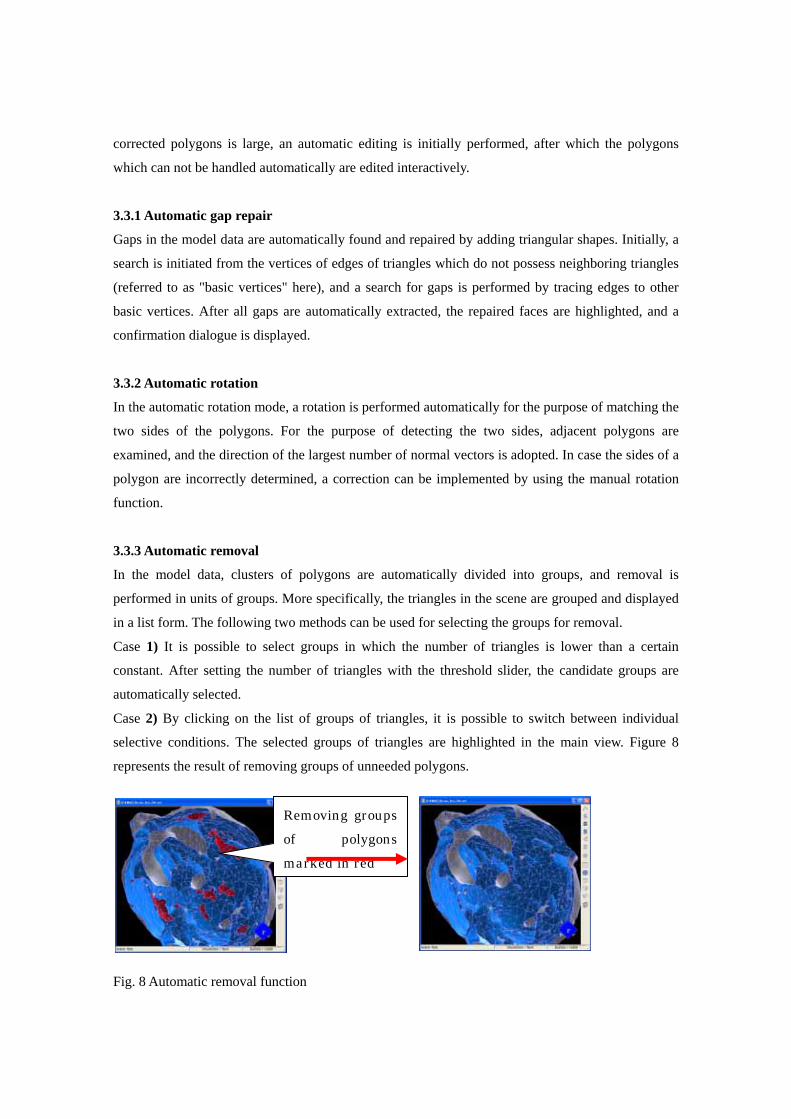
3.3.3 Automatic removal
In the model data, clusters of polygons are automatically divided into groups, and removal is
performed in units of groups. More specifically, the triangles in the scene are grouped and displayed
in a list form. The following two methods can be used for selecting the groups for removal.
Case 1) It is possible to select groups in which the number of triangles is lower than a certain
constant. After setting the number of triangles with the threshold slider, the candidate groups are
automatically selected.
Case 2) By clicking on the list of groups of triangles, it is possible to switch between individual
selective conditions. The selected groups of triangles are highlighted in the main view. Figure 8
represents the result of removing groups of unneeded polygons.
Fig. 8 Automatic removal function
Removing groups of polygons marked in red

4. Processing sequence In case bone shape (STL data) is outputted by using a 3D printer or a rapid prototyping device after
being extracted from CT and MR images, it is necessary to perform preliminary processing of the
image data and posterior processing of the reconstructed polygon data. In general, 3D printers print
the lines where the structural data crosses the horizontal surface, thus yielding a structure of stacked
layers. For this reason, it is necessary for the cross-sections of the reconstructed shape to be closed,
in other words, the line crossing the horizontal surface needs to be continuous in order to prevent
contradictions. Although the processing sequence differs depending on the removed part and the
modality (CT images, MR images, OCT, ultrasound, SPECT, etc.), in the present paper we present
an example of extracting a bone shape and the corresponding processing sequence[6].
4.1 Processing sequence for shape reconstruction
1) Extraction and editing of the necessary parts
Only the 3D image containing the part for extraction is cut (clipped) from the 3D image obtained by
CT or MR imaging. Furthermore, by utilizing relevant editing techniques, any unnecessary areas or
areas containing artifacts are removed from the clipped 3D image.
2) Segmentation
By using the classification segmentation function based on histograms, the brightness of all areas
apart from those corresponding to the bone is set to a specific value (e.g., zero), thus leaving only the
brightness values for the bone. In case the information regarding the internal part of the bone is
missing, the area expansion procedure is applied to the outer part of the bone. In this case, multiple
seed points (the initiation points for the area expansion) are placed on the outer part of the bone area,
and the outer part of the bone area is divided while adjusting the global and local parameters (the
parameters which control the degree of area expansion). Alternatively, seed points are placed in the
parts whose brightness values represent the bone area, and the continuous bone regions are extracted
while at the same time adjusting the parameters.
3) Image filtering and digitalization
The image filter of VE incorporates garbage removal and smoothing functions. In general, the
boundary between the cartilage and the bone is not clear, and furthermore, it is necessary to remove
the structures corresponding to muscle and tendon. For this purpose, the present function regards the
surface of the bone as smooth and presents a clear image of the bone boundary.
4) Image editing
In case it is necessary to close the surface of the clipped image, by using relevant editing functions,
the clipped surface is given the same brightness value as that of the extracted bone. If iso-surfaces
are generated by applying process 5, the cross-section of the generated surfaces crosses the surface
of the bone, thus forming a closed shape.
5) Generation of iso-surfaces
The 3D shape is reconstructed by taking the brightness values representing the bone boundary as
iso-surfaces. In case the amount of iso-surface data is too large, the 3D image data is compressed,
and either iso-surfaces are generated or the generated iso-surfaces (polygon data) are deleted.
Although the processing of compressed 3D data is fast, the surface shape is broken. For this reason,
it is possible to generate shapes with higher accuracy if the 3D data is not compressed and the
generated iso-surface data is processed with the data removal algorithm.
Figure 9 represents an example of iso-surface generated with the area expansion method on the basis
of binary 3D images divided into bone and other areas. The upper surface of the bone is not closed,
although it is necessary for the surface to be closed when using a 3D printer or a rapid prototyping
device. Although it is possible to utilize shape editing for the purpose of closing the boundary
surface, complex shapes require longer manipulation times. For this purpose, the slice image of the
boundary surface is colored using a value different from that of the rest of the bone by using the
image editing function. Figure 10 represents the result of the generation of iso-surfaces
corresponding to the 3D image, in which it is clear that the boundary surface is closed. Furthermore,
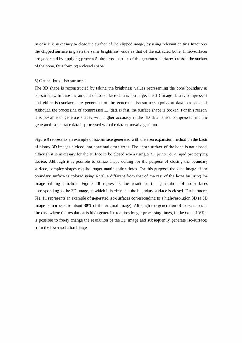
Fig. 11 represents an example of generated iso-surfaces corresponding to a high-resolution 3D (a 3D
image compressed to about 80% of the original image). Although the generation of iso-surfaces in
the case where the resolution is high generally requires longer processing times, in the case of VE it
is possible to freely change the resolution of the 3D image and subsequently generate iso-surfaces
from the low-resolution image.

Fig. 9 Segmentation and iso-surface generation by using the area expansion method (Low resolution:
370710 polygons)
Fig. 10 Generation of iso-surfaces corresponding to the 3D image with closed boundary surface
(Low resolution: 374379 polygons)
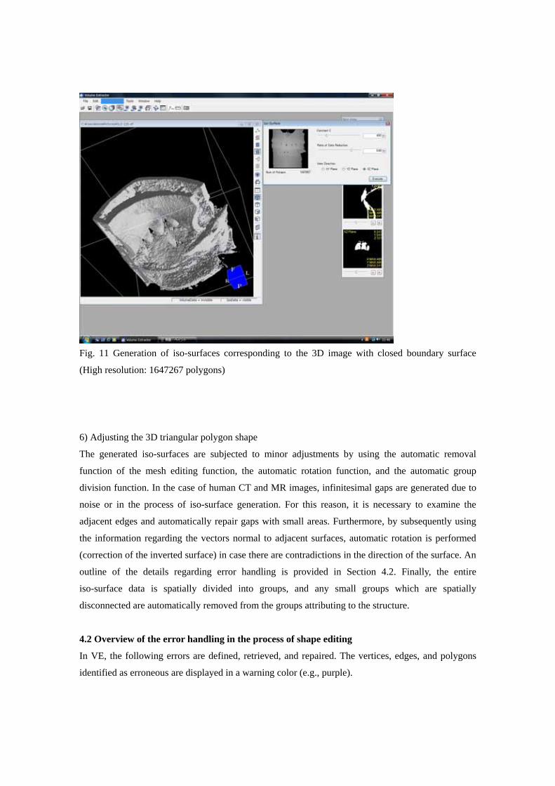
Fig. 11 Generation of iso-surfaces corresponding to the 3D image with closed boundary surface
(High resolution: 1647267 polygons)
6) Adjusting the 3D triangular polygon shape
The generated iso-surfaces are subjected to minor adjustments by using the automatic removal
function of the mesh editing function, the automatic rotation function, and the automatic group
division function. In the case of human CT and MR images, infinitesimal gaps are generated due to
noise or in the process of iso-surface generation. For this reason, it is necessary to examine the
adjacent edges and automatically repair gaps with small areas. Furthermore, by subsequently using
the information regarding the vectors normal to adjacent surfaces, automatic rotation is performed
(correction of the inverted surface) in case there are contradictions in the direction of the surface. An
outline of the details regarding error handling is provided in Section 4.2. Finally, the entire
iso-surface data is spatially divided into groups, and any small groups which are spatially
disconnected are automatically removed from the groups attributing to the structure.
4.2 Overview of the error handling in the process of shape editing
In VE, the following errors are defined, retrieved, and repaired. The vertices, edges, and polygons
identified as erroneous are displayed in a warning color (e.g., purple).
1) Error of overlapping vertices, edges, and polygons
・Vertex overlap error: indicates vertices whose coordinates overlap
・Edge overlap error: indicates edges composed of the same two vertices
・Polygon overlap error: indicates polygons composed of the same three edges
Overlap errors are retrieved automatically, and elements identified as erroneous are displayed in
green, as shown in Fig. 12.
2) One vertex - two edges connection error
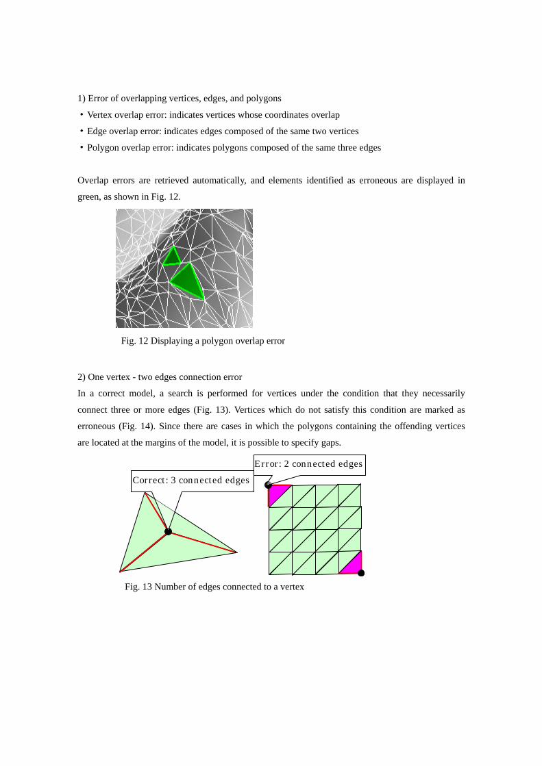
In a correct model, a search is performed for vertices under the condition that they necessarily
connect three or more edges (Fig. 13). Vertices which do not satisfy this condition are marked as
erroneous (Fig. 14). Since there are cases in which the polygons containing the offending vertices
are located at the margins of the model, it is possible to specify gaps.
Fig. 13 Number of edges connected to a vertex
Correct: 3 connected edges Error: 2 connected edges
Fig. 12 Displaying a polygon overlap error
3) One edge - two polygons connection error
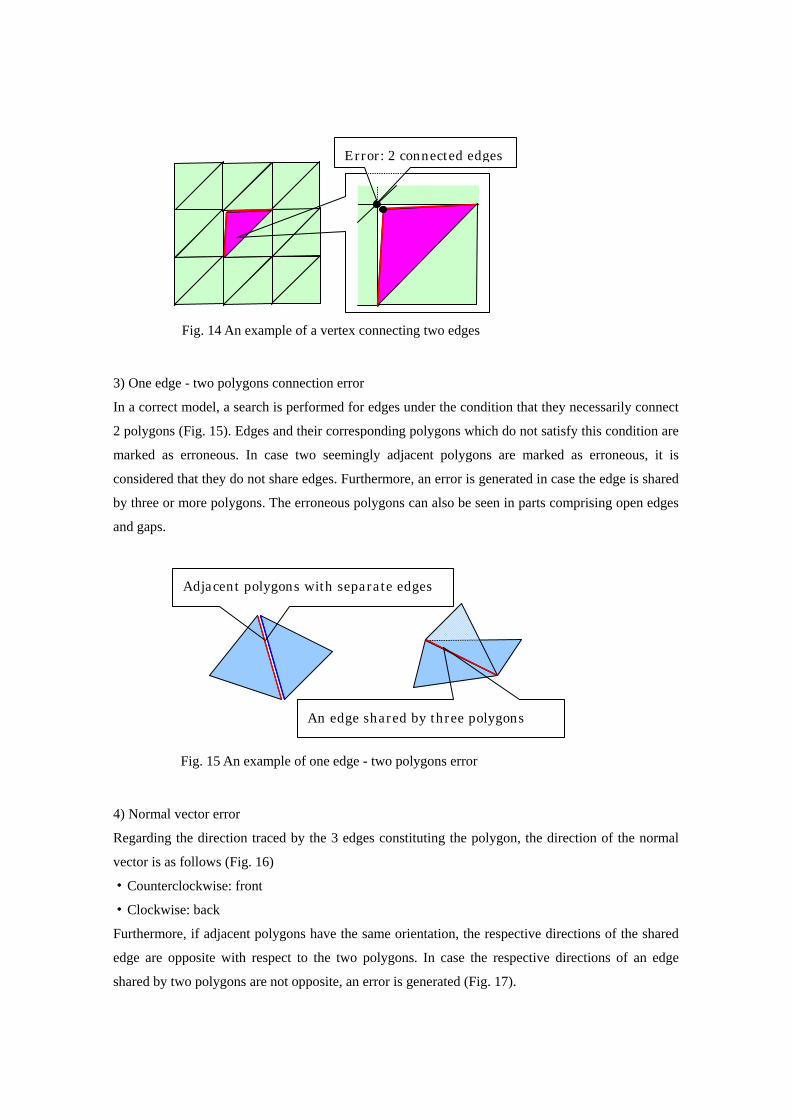
In a correct model, a search is performed for edges under the condition that they necessarily connect
2 polygons (Fig. 15). Edges and their corresponding polygons which do not satisfy this condition are
marked as erroneous. In case two seemingly adjacent polygons are marked as erroneous, it is
considered that they do not share edges. Furthermore, an error is generated in case the edge is shared
by three or more polygons. The erroneous polygons can also be seen in parts comprising open edges
and gaps.
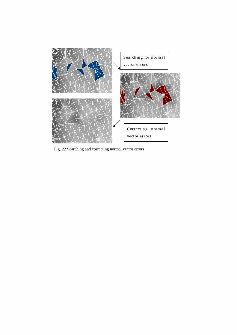
4) Normal vector error
Regarding the direction traced by the 3 edges constituting the polygon, the direction of the normal
vector is as follows (Fig. 16)
・Counterclockwise: front
・Clockwise: back
Furthermore, if adjacent polygons have the same orientation, the respective directions of the shared
edge are opposite with respect to the two polygons. In case the respective directions of an edge
shared by two polygons are not opposite, an error is generated (Fig. 17).
Fig. 15 An example of one edge - two polygons error
Error: 2 connected edges
Fig. 14 An example of a vertex connecting two edges
Adjacent polygons with separate edges
An edge shared by three polygons
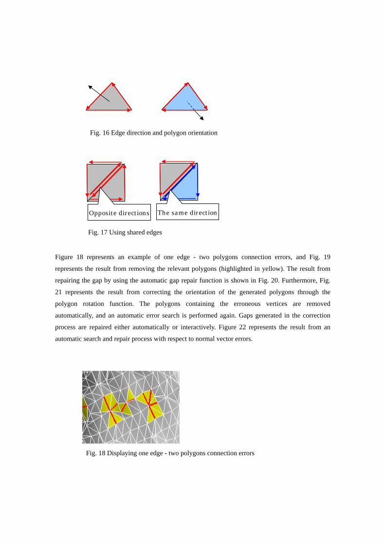
Figure 18 represents an example of one edge - two polygons connection errors, and Fig. 19
represents the result from removing the relevant polygons (highlighted in yellow). The result from
repairing the gap by using the automatic gap repair function is shown in Fig. 20. Furthermore, Fig.
21 represents the result from correcting the orientation of the generated polygons through the
polygon rotation function. The polygons containing the erroneous vertices are removed
automatically, and an automatic error search is performed again. Gaps generated in the correction
process are repaired either automatically or interactively. Figure 22 represents the result from an
automatic search and repair process with respect to normal vector errors.
Fig. 18 Displaying one edge - two polygons connection errors
The same directionOpposite directions
Fig. 17 Using shared edges
Fig. 16 Edge direction and polygon orientation

Fig. 21 Rotation after all gaps have been repaired
Fig. 20 The result of automatically repairing the gaps once
Although the gap was repaired, an inversion is necessary
Fig. 19 Repairing one edge - two polygons connection errors
Searching for normal vector errors
Correcting normal vector errors
Fig. 22 Searching and correcting normal vector errors

5. Conclusion The present paper presents an overview of the features of VE Ver. 3.0, with detailed explanation of
the concept and the operation of the shape reconstruction functions. VE Ver. 3.0 includes the
functions of SMESH Ver. 1.0 and is capable of transforming segmented 3D images (of internal
organs, bones, blood vessels, etc.) into triangle polygon data, editing the resulting polygon data, and
preparing actual models in a simple manner by utilizing a 3D printer or a rapid prototyping device.
The 3D models prepared with the aid of VE can be utilized in many fields of medicine and
engineering. For example, shape models containing internal organs, bones, and blood vessels can be
used for preoperative planning, operation simulations, medical education, using virtual reality (VR)
to obtain informed consent from patients c), and so on. The plan for future development includes the
improvement of the user interface, the implementation of functions such as the ability to add color to
the shape data, the ability to create actual models as combinations of internal organs, skeletal
structure, and blood vessels, the ability to divide the reconstructed shape into a mesh of tetragons or
hexahedrons, and the ability to perform high-speed processing of high-resolution images.
A trial version of the present software (Volume Extractor Ver. 3.0 Light 32/64 bit edition) can be
downloaded from the home page of i-Plants Systems, Ltd. [7].
6. Acknowledgements We express our gratitude to the "Supporting Program for Creating University Ventures" of the Japan
Science and Technology Agency for providing support for the development of the present software.
We are particularly indebted to Prof. Suzuki Masahiko and Prof. Haneishi Hideaki from Chiba
University for the numerous discussions and strong support with respect to the abovementioned
matters. The cooperation of the Department of Orthopedic Surgery, Chiba University, and the
Department of Medicine, Iwate Prefectural University was received in obtaining the CT and MR
image data used in the present research. Furthermore, we express our deep gratitude to Prof. Ogawa
Akira from Iwate Medical University, Prof. Inoue Kei from Kohnan Hospital, and Mr. Tokuda
Masayuki, who is a visiting professor at the Advanced Visualization Research Laboratory at Iwate
Prefectural University, for their valuable feedback.
c) VR VR is an abbreviation of Virtual Reality, which generally represents techniques and systems for generating a virtual world (cyberspace) by using computers and has connections with technology related to computer graphics, networks, voice and touch.

References
[1] A. Doi, "Research development of software techniques focusing on 3D medical image processing", Intelligent Cosmos Academic Foundation, Vol. 9, pp. 9-12, ANNAL 2005, (2005)
[2] A. Doi, S. Mega, "Face removal, gap repair and inversion tool "SMESH"", Image lab, Dec. 2006, pp. 42-47, Japan Industrial Publishing (2006)
[3] Marubeni Information Systems, "Dimension3D printer", http://www.marubeni-sys.com/de/dimension/, 2008
[4] A. Doi, "On image processing techniques for medicine and medical engineering coordination", text for the 253rd Deformation Processing Symposium, Japan Society for Technology and Plasticity, (2007)
[5] S. Suzuki, K. Matsui, F. Yamasa, F. Itoh A. Doi, "Volume Extractor Ver. 3.0 operation manual", http:/www.i-plants.jp/hp, 2008
[6] A. Doi, S. Suzuki,F. Yamasa,K. Matsui,F. Itoh,S. Mega,S. Itoh, "Volume Extractor Ver. 3.0 -3D image processing and shape reconstruction-", 239th conference of The Institute of image Electronics Engineers of Japan, 2008
[7] i-Plants Systems, Ltd, ”VE Ver.3.0”, http://www.i-plants.co.jp/hp/download/, 2008