a a a - oregon.gov · preboring requirements, vibration monitoring, dynamic pile testing...
TRANSCRIPT
GEOTECHNICAL DESIGN MANUAL CHAPTER 18- CONSTRUCTION RECOMMENDATIONS AND REPORT
GEO-ENVIRONMENTAL SECTION
OREGON DEPARTMENT OF TRANSPORTATION
VERSION 2.0
6/1/2018
CHAPTER 18- CONSTRUCTION RECOMMENDATIONS AND REPORT
GEOTECHNICAL DESIGN MANUAL Page 2 of 14
TABLE OF CONTENTS SUMMARY OF CHANGES ............................................................................................................................... 3
18 CONSTRUCTION RECOMMENDATIONS AND REPORT ...................................................................... 4
18.1 GENERAL ......................................................................................................................................................4
18.2 ROADWAY CONSTRUCTION SUPPORT ......................................................................................................4
18.3 BRIDGE CONSTRUCTION SUPPORT ...........................................................................................................4
18.3.1 SPREAD FOOTING CONSTRUCTION ....................................................................................... 4
18.3.2 DRIVEN PILE CONSTRUCTION ................................................................................................ 5
18.3.3 DRILLED SHAFT CONSTRUCTION ............................................................................................ 6
18.4 REFERENCES ............................................................................................................................................. 10
APPENDIX .................................................................................................................................................... 11
LIST OF FIGURES .................................................................................................................................................... 11
18.5 APPENDIX 18-A: PILE INSPECTOR GRAPH............................................................................................... 12
18.6 APPENDIX 18-B: HAMMER APPROVAL LETTER ..................................................................................... 13

CHAPTER 18- CONSTRUCTION RECOMMENDATIONS AND REPORT
GEOTECHNICAL DESIGN MANUAL Page 3 of 14
SUMMARY OF CHANGES
Chapter Summary of changes made Date revised
18 Updated All Chapter Content 3/28/2018
CHAPTER 18- CONSTRUCTION RECOMMENDATIONS AND REPORT
GEOTECHNICAL DESIGN MANUAL Page 4 of 14
18 CONSTRUCTION RECOMMENDATIONS AND REPORT
18.1 GENERAL
Most construction recommendations should be included in the project Special Provisions or shown on the plans if they are to be contractually recognized. Construction recommendations can also be included in the final geotechnical report as appropriate and may include discussions or recommendations on the following items:
Temporary shoring requirements
Control of groundwater in excavations
Temporary excavation slopes
Difficult pile driving conditions
Boulders or other obstructions expected in the area of foundation construction or excavations
Existing foundations in the area of proposed foundations or excavations
Monitoring of adjacent structures or facilities (preconstruction surveys)
Underwater acoustic monitoring of pile driving or “bubble curtains”
Monitoring of fill settlement and excess pore pressure
Existing utilities, drainage pipes or other feature that may influence foundation construction
Other unique construction recommendations or quality control issues should be appropriately addressed.
18.2 ROADWAY CONSTRUCTION SUPPORT
The geotechnical designer and/or project geologist should read, and be familiar with, the ODOT Standard Specifications for Roadwork (Section 00300) and specifically Section 00330, “Earthwork.” Also, review all the Standard Special Provisions for Section 00300. Provide construction assistance for the following items as required:
Review of material properties of proposed embankment,
Review any embankment settlement monitoring data,
Assist with assessment of unanticipated subgrade stabilization needs,
Assist with solutions to drainage problems or other groundwater issues,
Provide solutions and options for dealing with unstable cut slopes if they arise,
Review of proposed blasting plans.
18.3 BRIDGE CONSTRUCTION SUPPORT
Provide review of contractor submittals and provide construction support as needed for the following general items related to bridge foundation construction:
Review the stability of temporary excavation cut slopes and shoring submittals,
Review of foundation designs for false work,
Review of foundations for temporary work bridges or detour bridges,
Review cofferdam designs,
Review and assist in approval of change orders regarding foundation related items such as changes to material specifications or foundation materials,
Drilled shaft and pile hammer submittals.
18.3.1 SPREAD FOOTING CONSTRUCTION The geotechnical designer should be familiar with the “ODOT Standard Specifications for Structure Excavation and Backfill (Section 00510)”. Provide inspection services to the field as requested to verify
CHAPTER 18- CONSTRUCTION RECOMMENDATIONS AND REPORT
GEOTECHNICAL DESIGN MANUAL Page 5 of 14
that the foundation materials exposed at the footing foundation elevation are the same materials as assumed in design and suitable for foundation support. If the materials are not as assumed and are not suitable for footing construction, provide recommendations to the construction office regarding how to proceed with foundation construction. Consult with the structure designer and other project personnel, as necessary, if significant changes to footing elevations are required.
18.3.2 DRIVEN PILE CONSTRUCTION The geotechnical designer should be familiar with the “ODOT Standard Specifications for Driven Piles (Section 00520)” and the “Standard Special Provisions for Section 00520” which supplement the Standard Specifications. The final pile record books should be sent to the HQ Bridge Engineering Section office at the completion of the project. These records are scanned into a database for future reference.
Construction support for pile foundation projects typically consists of the following review process and documentation:
Review and approval of the Pile & Driving Equipment Data Form.
o The contractor is required to submit a completed Pile & Driving Equipment Data Form. If the form is not complete or unclear, request a resubmittal from the PM office. This review consists of verifying that the contractor’s hammer meets the requirements of the standard specifications, which typically means the proposed hammer will provide sufficient field energy to drive the piles to the required minimum tip elevation and develop the required nominal resistance with a driving resistance within the allowable range of 3 to 15 blows per in.
o If the piles are driven to bearing based on the FHWA dynamic formula, simply check to see that, for the required nominal resistance, the estimated hammer field energy will result in a resistance between 3 and 15 blows per in. The maximum rated hammer energy should not be used in this evaluation since hammers rarely reach this level of performance.
o If the piles are accepted based on wave equation (WEAP) analysis, check the contractor’s WEAP analysis to see that the correct input values were used, the analysis was performed properly, and the predicted pile stresses are below the maximum stresses allowed. Also, check to see that the predicted resistance is between 3 and 15 blows per in.
o If swinging leads are proposed, there should be a clear method of bracing, anchoring or fixing the bottom of the leads to maintain proper hammer-pile alignment throughout the pile installation.
Provide final pile driving criteria to the field.
o If the hammer does not meet the requirements of the specifications, provide a letter to the PM office rejecting the hammer and documenting the reasons for the rejection. Once the hammer is accepted, a letter stating so is sent to the project manager along with the final driving criteria.
The final pile driving criteria usually consists of an inspectors graph showing the required resistance in blows per inch as a function of hammer stroke (for open-end diesel hammers) or field energy. An example is attached in Appendix 18-A: Pile Inspector Graph. A table showing the required resistance as a function of hammer stroke (for a fixed nominal resistance) may also be provided.
At this time in the pile hammer review and approval process, any important pile installation problems or issues that might arise should be communicated to the project manager and the pile inspector in the pile hammer approval letter. The following issues should be discussed as applicable:
Pile freeze (setup) period, if required, and proper procedures to follow,
Any anticipated difficult driving conditions and damage potential,
Potential for piles running long and possible solutions,

CHAPTER 18- CONSTRUCTION RECOMMENDATIONS AND REPORT
GEOTECHNICAL DESIGN MANUAL Page 6 of 14
Preboring requirements,
Vibration monitoring,
Dynamic pile testing requirements and procedures.
An example of a pile hammer approval letter is shown in Appendix 18-B: Hammer Approval Letter.
For open-end diesel hammers, the hammer stroke must be determined during pile driving for use in determining bearing resistance. A saximeter is a small hand-held device that measures and records hammer stroke and other pile driving information during driving. These devices are available for loan to the field from the HQ Bridge Engineering Section for use in measuring and monitoring the field hammer stroke and other data. Saximeters are primarily recommended for monitoring stroke for open-end diesel hammers and are helpful in assessing overall hammer performance.
18.3.3 DRILLED SHAFT CONSTRUCTION The geotechnical designer should be familiar with the “ODOT Standard Specifications for Drilled Shafts (Section 00512)” and the “Standard Special Provisions for Section 00512” which supplement the Standard Specifications. The project Special Provisions may contain several specifications pertaining to drilled shaft construction that are unique to a given project.
Proper inspection is a crucial element in the drilled shaft construction process. All drilled shaft inspectors should be certified in drilled shaft inspection procedures.
Construction support for drilled shaft projects typically consists of the following items:
Review and approval of the drilled shaft installation plan and other submittals (see Section 0512.40 of the Standard Specifications). This review and approval should be coordinated closely with the structural designer. Shaft construction methods can affect both the structural and geotechnical capacity of drilled shafts and so both disciplines should be involved in this review.
Attend drilled shaft preconstruction meetings with the drilled shaft subcontractor, prime contractor, and construction staff.
Review and approve crosshole sonic log test results. Coordinate the review and approval of CSL test results closely with the structural designer. See Section 18.3.3.1 for details regarding the CSL testing and evaluation procedures.
Review proposed drilled shaft repair plans (as needed).
Provide construction support and advice to the construction office during shaft construction regarding any difficulties in shaft construction or to answer any questions the inspector may have. Help insure the proper inspection is taking place and the proper inspection forms are being completed.
Work with the inspector to make sure the shaft is being constructed in the foundation materials that were assumed in design. If changes to the estimated shaft tip elevations are necessary, work with the structural designer and project staff to determined acceptable revised shaft tip elevations.
18.3.3.1 CROSSHOLE SONIC LOG (CSL) TESTING & EVALUATION PROCEDURES CSL testing, in combination with a quality field inspection, are the primary methods used by ODOT for the quality control and acceptance of drilled shafts. CSL testing is not always a conclusive test and the results often require interpretation and further in-depth review. The CSL test results by themselves can sometimes be misleading. Therefore, all inspection records and forms should be provided to the CSL reviewer to use in combination with the CSL test results in determining shaft acceptance. It is highly recommended that the foundation and bridge designers both understand, and be familiar with, CSL testing procedures and have training in the use and interpretation of CSL test results.

CHAPTER 18- CONSTRUCTION RECOMMENDATIONS AND REPORT
GEOTECHNICAL DESIGN MANUAL Page 7 of 14
The following procedures should be used when conducting CSL testing for quality control of drilled shafts on ODOT projects.
18.3.3.2 CSL FIELD TESTING
Contractor provides the CSL subcontractor to do the testing. This is included in the contract with bid items for the number of CSL tests per bridge. The qualifications of the CSL contractor are submitted for approval as part of the Drilled Shaft Installation Plan.
CSL testing is performed according to ASTM D6760-02.
CSL testing is performed on the first shaft constructed and others as described in Section 00512 of the special provisions or as directed by the Engineer.
Additional shafts are tested if construction methods change or shaft construction results in questionable quality shafts. This is especially true for uncased shafts, excavated below the water table.
18.3.3.3 CSL TEST RESULTS
CSL test results should be forwarded to both the geotechnical engineer and the bridge designer for review, (regardless of what the CSL report from the contractor says).
Both engineers should concur that the shaft is acceptable or needs further investigation.
Structural and/or geotechnical analysis may be necessary at this point to assess the load carrying capacity of the shaft based on interpretation of the CSL test results and inspection reports.
18.3.3.4 FURTHER TESTING/INSPECTION If an anomaly or obvious defect is detected in the CSL testing, it may warrant further investigation to verify that it does indeed exist and to further quantify the extent and material properties of the material in the affected zone. If additional investigation appears necessary, review all the shaft inspection forms and confer immediately with the drilled shaft Inspector regarding all aspects of shaft construction to determine what could have happened at the depth of the anomaly.
Note: This is a very important decision in that if, upon further investigation, there is no shaft defect found; ODOT may be responsible for paying the investigation costs along with additional compensation to the contractor for delaying drilled shaft construction due to the additional investigation work. If any defects are found, regardless of whether they are repaired or not, the full cost of the shaft investigation (coring and/or other work) is paid by the Contractor with no time extension.
If further investigation is deemed necessary, the following procedures should be considered to further quantify the affected zone:
First, thoroughly review the inspection records of the drilled shaft in question and review the closest drill log to see if there is a correlation between the detected anomaly and something that occurred during the shaft construction process and/or related to the soils or groundwater conditions.
Consider performing additional CSL testing after some period of time to see if the anomaly is the result of delayed concrete set or curing. Check concrete mix design to see if admixtures and retarders were used which could delay concrete set.
If practical, excavate around the perimeter of the shaft to expose near-surface defects.
Consider using CSL tomography (3D Imaging) at this time to try and better define the extent of the anomaly.
If required, perform core drilling at the locations and depths of suspected defects.
Insert downhole cameras (in drilled core holes) for visual examination of defects.
CHAPTER 18- CONSTRUCTION RECOMMENDATIONS AND REPORT
GEOTECHNICAL DESIGN MANUAL Page 8 of 14
18.3.3.5 CORE DRILLING If core drilling is necessary, the following procedures should be followed:
The foundation or bridge designer should plan the number, location, and depth of all core holes based on the CSL test results and inspection reports. Target the area(s) where the CSL results indicate possible defects. Do not allow the contractor to select core hole numbers, locations and depths.
Use either double or triple tube-coring equipment that will result in maximum recovery and minimal damage to the recovered concrete core.
Carefully log all core holes using methods similar to those used for typical geotechnical bore holes, closely measuring depths, rate of advancement, any sudden drops in drill steel (indicating voids), percent recovery, concrete quality, breaks, fractures, inclusions and anything that does not indicate solid, good quality concrete.
Core at least 3” away from any rebar, if possible, and do not core through any steel reinforcement without the clear, expressed approval of the structural designer.
Take photos of the core recovery.
Keep notes of any driller remarks regarding the nature and quality of the shaft concrete.
Keep the contractor (or Drilled Shaft subcontractor) informed throughout this investigation. The core holes may be able to be used by the contractor for repairing any shaft defects.
Cored holes could also be filled with water and used for additional CSL testing.
If possible: o Do core breaks (qu) on suspected core samples retrieved from defect area. o Use down-hole cameras to help quantify the extent of defect area.
18.3.3.6 SHAFT DEFECTS AND REPAIRS Based on the results of the additional investigation work and an assessment of the shaft integrity, the bridge and foundation designers should confer and determine if a defect is present that requires repair. This determination should be based on an assessment of the effect the defect has on the shaft’s ability to perform as designed (both for geotechnical and structural purposes).
Note: If a shaft defect is determined to be present, it is the contractor’s responsibility to submit a repair plan and repair the defect at no cost to ODOT.
All shaft repair proposals should be submitted to the foundation and bridge designers for review and approval. Shaft repair should not be allowed without written approval of the Engineer-of-Record. Grout repair of minor shaft voids may be allowed with approval of the Engineer-of-Record, if the CSL tubes are left open to verify shaft integrity after grouting. If shaft defects are severe enough to warrant complete shaft replacement or redesign, the contractor shall submit a plan for the redesign or replacement according to Section 00512.41.
If there is no shaft defect found, ODOT may be responsible for paying the investigation costs and additional approved compensation to the contractor for delaying drilled shaft construction due to the additional investigation work. If any defects are found, regardless of whether they are repaired or not, the full cost of the shaft investigation (coring and/or other work) is paid by the Contractor with no time extension.
18.3.3.7 REMAINING SHAFTS The cause of any defects should be ascertained, if at all possibly, so the contractor can use modified shaft construction procedures and avoid repeating the same defects in the remaining drilled shafts on

CHAPTER 18- CONSTRUCTION RECOMMENDATIONS AND REPORT
GEOTECHNICAL DESIGN MANUAL Page 9 of 14
the project. A modified drilled shaft installation plan, showing these modifications to the installation procedures, should be submitted for approval.

CHAPTER 18- CONSTRUCTION RECOMMENDATIONS AND REPORT
GEOTECHNICAL DESIGN MANUAL Page 10 of 14
18.4 REFERENCES
This section blank intentionally.

APPENDIX – LIST OF TABLES
GEOTECHNICAL DESIGN MANUAL Page 11 of 14
APPENDIX
LIST OF FIGURES
Figure 18.1 PILE INSPECTOR GRAPH ............................................................................................... 12

APPENDIX 18-A: PILE INSPECTOR GRAPH
GEOTECHNICAL DESIGN MANUAL Page 12 of 14
18.5 APPENDIX 18-A: PILE INSPECTOR GRAPH
Figure 18.1 PILE INSPECTOR GRAPH
Geary Canal Bridge No. 18142; Bent 4Qult = 295 kips
PP18x0.375, Delmag D25-32L = 103', Qs = 95%
0.0
0.5
1.0
1.5
2.0
2.5
3.0
4 5 6 7 8 9 10 11 12
Stroke, Feet
Re
qu
ire
d R
es
ista
nc
e,
blo
ws
pe
r in
ch
0
5
10
15
20
25
30
35
40
45
Pile
Str
es
se
s, k
si
Resistance
Pile Stresses
APPENDIX 18-B: HAMMER APPROVAL LETTER
GEOTECHNICAL DESIGN MANUAL Page 13 of 14
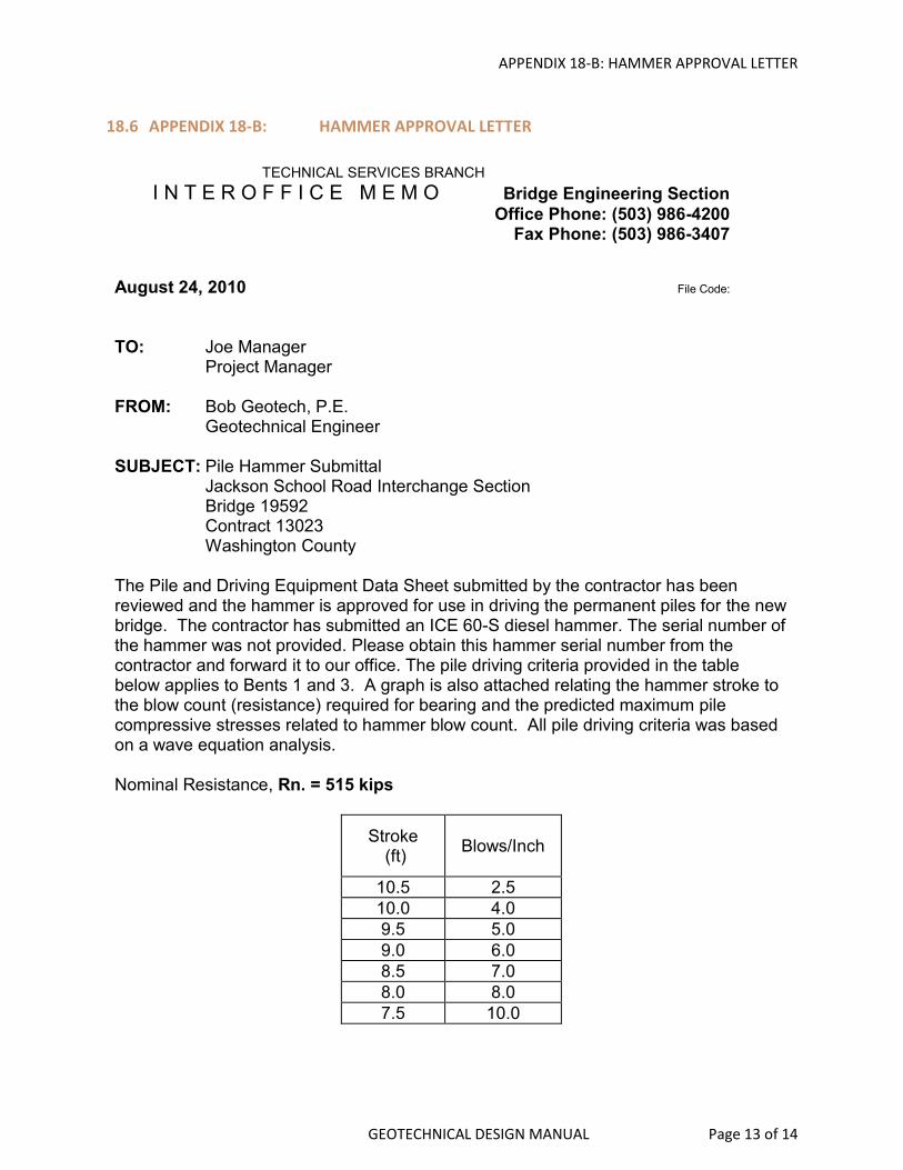
18.6 APPENDIX 18-B: HAMMER APPROVAL LETTER
TECHNICAL SERVICES BRANCH
I N T E R O F F I C E M E M O Bridge Engineering Section
Office Phone: (503) 986-4200 Fax Phone: (503) 986-3407
August 24, 2010 File Code:
TO: Joe Manager Project Manager FROM: Bob Geotech, P.E. Geotechnical Engineer SUBJECT: Pile Hammer Submittal
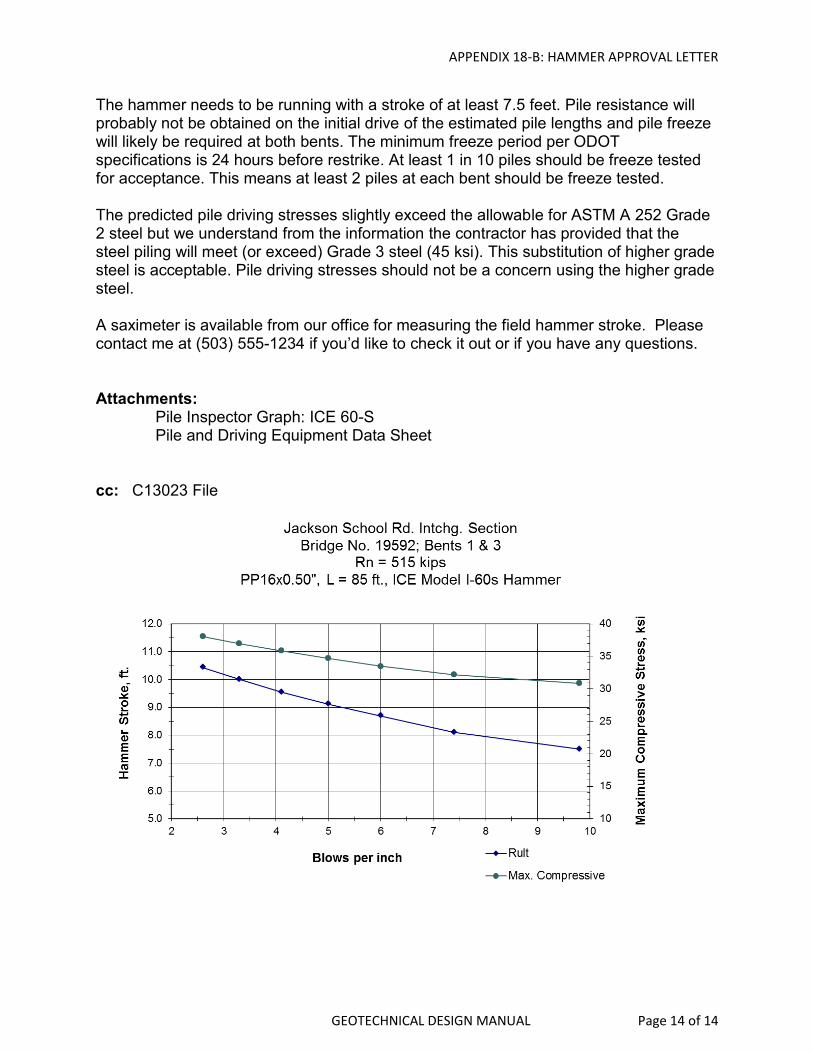
Jackson School Road Interchange Section Bridge 19592 Contract 13023 Washington County The Pile and Driving Equipment Data Sheet submitted by the contractor has been reviewed and the hammer is approved for use in driving the permanent piles for the new bridge. The contractor has submitted an ICE 60-S diesel hammer. The serial number of the hammer was not provided. Please obtain this hammer serial number from the contractor and forward it to our office. The pile driving criteria provided in the table below applies to Bents 1 and 3. A graph is also attached relating the hammer stroke to the blow count (resistance) required for bearing and the predicted maximum pile compressive stresses related to hammer blow count. All pile driving criteria was based on a wave equation analysis. Nominal Resistance, Rn. = 515 kips
Stroke (ft)
Blows/Inch
10.5 2.5
10.0 4.0
9.5 5.0
9.0 6.0
8.5 7.0
8.0 8.0
7.5 10.0
APPENDIX 18-B: HAMMER APPROVAL LETTER
GEOTECHNICAL DESIGN MANUAL Page 14 of 14
The hammer needs to be running with a stroke of at least 7.5 feet. Pile resistance will probably not be obtained on the initial drive of the estimated pile lengths and pile freeze will likely be required at both bents. The minimum freeze period per ODOT specifications is 24 hours before restrike. At least 1 in 10 piles should be freeze tested for acceptance. This means at least 2 piles at each bent should be freeze tested. The predicted pile driving stresses slightly exceed the allowable for ASTM A 252 Grade 2 steel but we understand from the information the contractor has provided that the steel piling will meet (or exceed) Grade 3 steel (45 ksi). This substitution of higher grade steel is acceptable. Pile driving stresses should not be a concern using the higher grade steel. A saximeter is available from our office for measuring the field hammer stroke. Please contact me at (503) 555-1234 if you’d like to check it out or if you have any questions. Attachments: Pile Inspector Graph: ICE 60-S Pile and Driving Equipment Data Sheet cc: C13023 File