a bar subjected to torsion is called a shaft. in torsion ... · pdf filelecture 12 strength of...
TRANSCRIPT
V. DEMENKO MECHANICS OF MATERIALS 2015
1
LECTURE 12 Strength of a Bar in Torsion
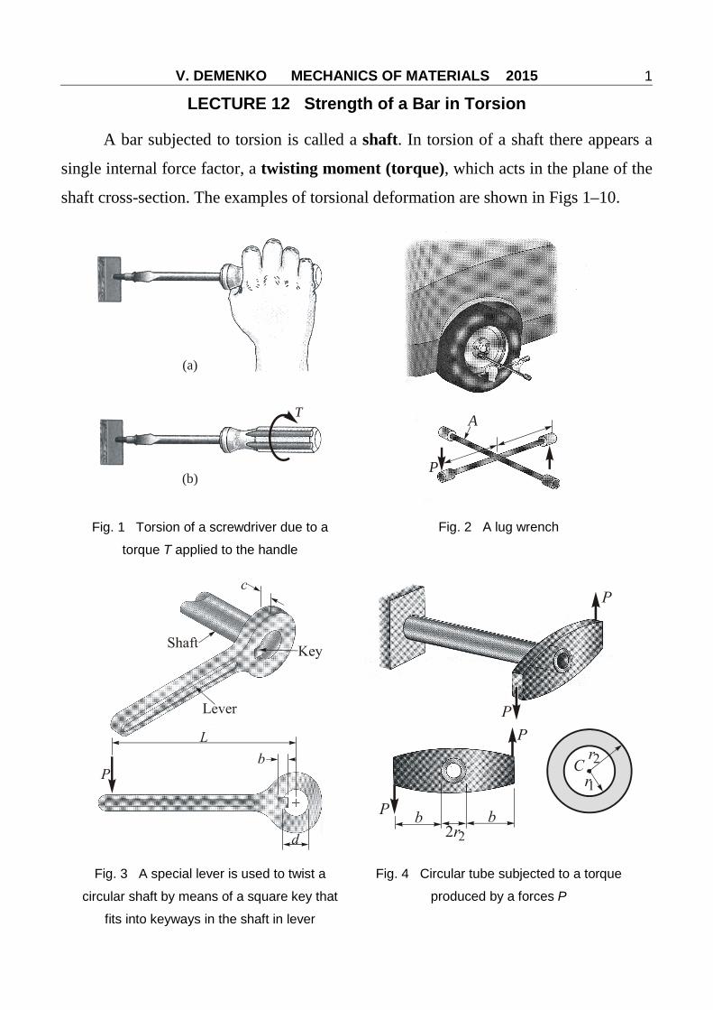
A bar subjected to torsion is called a shaft. In torsion of a shaft there appears a
single internal force factor, a twisting moment (torque), which acts in the plane of the
shaft cross-section. The examples of torsional deformation are shown in Figs 1–10.
T
(a)
(b)
A
P
Fig. 1 Torsion of a screwdriver due to a
torque T applied to the handle
Fig. 2 A lug wrench
Fig. 3 A special lever is used to twist a
circular shaft by means of a square key that
fits into keyways in the shaft in lever
Fig. 4 Circular tube subjected to a torque
produced by a forces P
V. DEMENKO MECHANICS OF MATERIALS 2015
2
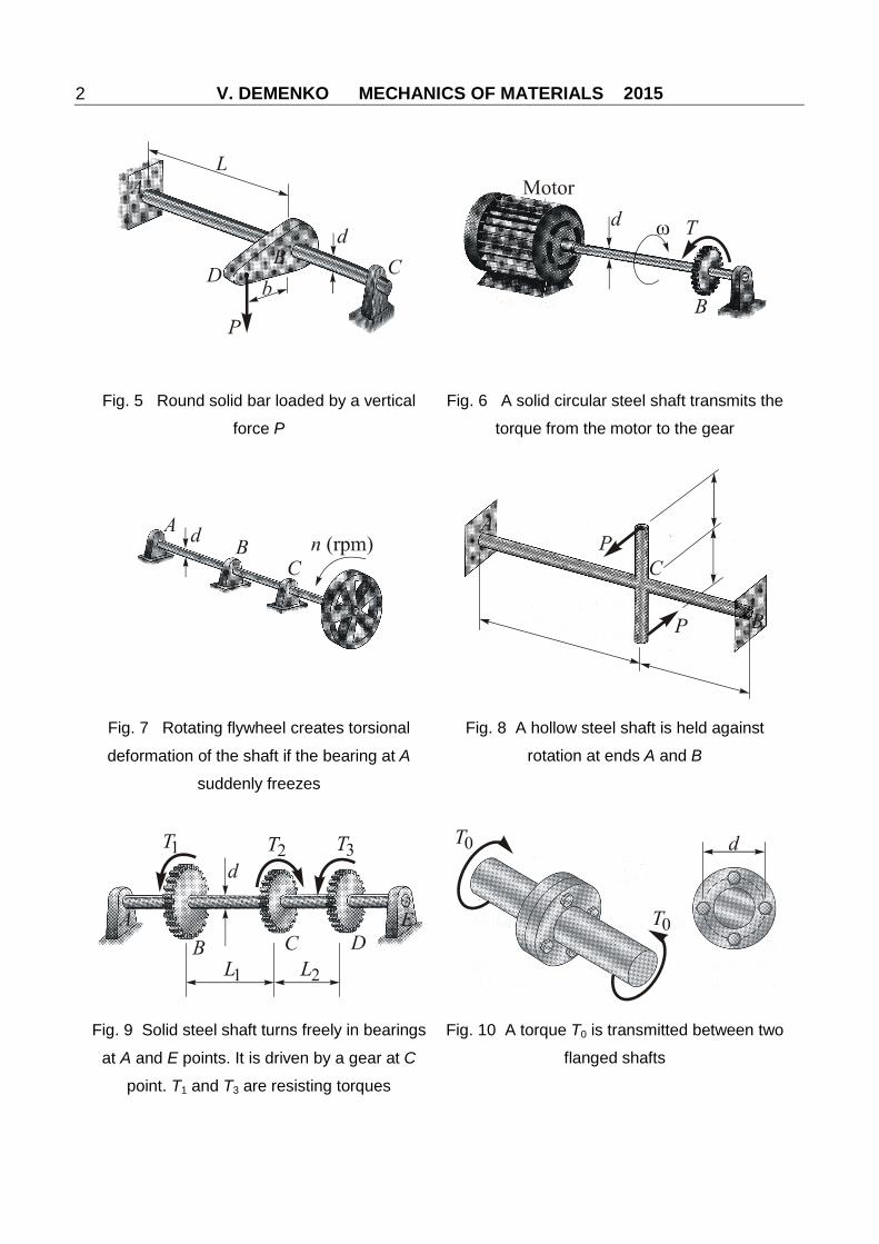
Fig. 5 Round solid bar loaded by a vertical
force P
Fig. 6 A solid circular steel shaft transmits the
torque from the motor to the gear
Fig. 7 Rotating flywheel creates torsional
deformation of the shaft if the bearing at A
suddenly freezes
Fig. 8 A hollow steel shaft is held against
rotation at ends A and B
Fig. 9 Solid steel shaft turns freely in bearings
at A and E points. It is driven by a gear at C
point. T1 and T3 are resisting torques
Fig. 10 A torque T0 is transmitted between two
flanged shafts
V. DEMENKO MECHANICS OF MATERIALS 2015
3
1 Correlation Between Shearing Stress and Twisting Moment
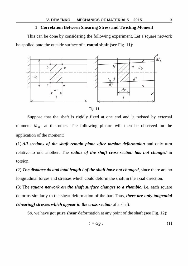
This can be done by considering the following experiment. Let a square network
be applied onto the outside surface of a round shaft (see Fig. 11):
Fig. 11
Suppose that the shaft is rigidly fixed at one end and is twisted by external
moment KM at the other. The following picture will then be observed on the
application of the moment:
(1) All sections of the shaft remain plane after torsion deformation and only turn
relative to one another. The radius of the shaft cross-section has not changed in
torsion.
(2) The distance dx and total length l of the shaft have not changed, since there are no
longitudinal forces and stresses which could deform the shaft in the axial direction.
(3) The square network on the shaft surface changes to a rhombic, i.e. each square
deforms similarly to the shear deformation of the bar. Thus, there are only tangential
(shearing) stresses which appear in the cross section of a shaft.
So, we have got pure shear deformation at any point of the shaft (see Fig. 12):
= Gτ γ . (1)

V. DEMENKO MECHANICS OF MATERIALS 2015
4
In Fig. 12 which shows the equilibrium of
infinitesimally in length segment of the shaft under
internal torque moment xM it is seen that
02
≤ ≤D
ρ , ′ = =dd dx dγ ρ ϕ ,
hence
=ddxϕ
γ ρ (2)
where γ is an angle of shear; dϕ is an elementary angle of twist.
To go over to shear stresses, let us use Hooke's law in shear and substitute into
it the expression for γ :
= =dG Gdxϕ
τ γ ρ . (3)
If an elementary area dA at a distance ρ from the
centroid of the section is acted upon by the stress τ , the
elementary torque moment will be equal to the
elementary force dAτ multiplied by the polar radius ρ
(Fig. 13):
=xdM dAτρ .
The total moment can be obtain by summing the elementary moments over the
area of the section:
2= =∫ ∫xA A
dM dA G dAdxϕ
τρ ρ . (4)
It may be recalled that the integral obtained
2 =∫A
dA Iρρ
Fig. 12
Fig. 13
V. DEMENKO MECHANICS OF MATERIALS 2015
5
is called the polar moment of inertia. The expression for xM can then be rewritten as
follows:
=xdM GIdxρϕ ,
whence we obtain
= xMddx GIρ
ϕ . (5)
According to expression (3)
=ddx Gϕ τ
ρ. (6)
Consequently
= xMG GIρ
τρ
→ ( ) = xMIρ
ρτ ρ . (7)
As may be seen from this formula, shearing stresses are directly proportional to
the radius of a point. They are distributed over the cross-section according to a linear
law and have a maximum value at points most remote from the axis of the shaft.
Then
maxmax = xM
Iρ
ρτ . (8)
The quantity
max=
I Wρρ
ρ[m3] (9)
is called the polar section(al) modulus.
For circular sections of diameter D:
4
32=
DIρπ ,
4 3:
32 2 16= =
D D DWρπ π , (10)
V. DEMENKO MECHANICS OF MATERIALS 2015
6
and for a tubular section (hollow shaft):
( )3 4116
= −DW π
αρ ; =dD
α . (11)
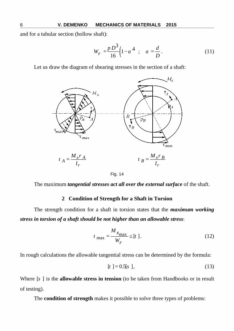
Let us draw the diagram of shearing stresses in the section of a shaft:
= x AA
MIρ
ρτ = x B
BM
Iρ
ρτ
Fig. 14
The maximum tangential stresses act all over the external surface of the shaft.
2 Condition of Strength for a Shaft in Torsion
The strength condition for a shaft in torsion states that the maximum working
stress in torsion of a shaft should be not higher than an allowable stress:
maxmax [ ]= ≤
M xW
τ τρ
. (12)
In rough calculations the allowable tangential stress can be determined by the formula:
[ ] 0.5[ ]=τ σ , (13)
Where [ ]σ is the allowable stress in tension (to be taken from Handbooks or in result
of testing).
The condition of strength makes it possible to solve three types of problems:
V. DEMENKO MECHANICS OF MATERIALS 2015
7
1) estimate (check) the strength of a shaft for specified load and dimensions using the
condition:
max [ ]≤τ τ ; (14)
2) determine the required polar sectional modulus in torsion and diameter by the
specified allowable stress [ ]τ and load xM :
[ ]≥ xMWρ τ
; (15)
3) determine the allowable load on a shaft by the specified allowable stress and
geometrical dimensions of the shaft section:
[ ] [ ]=xM Wρτ . (16)
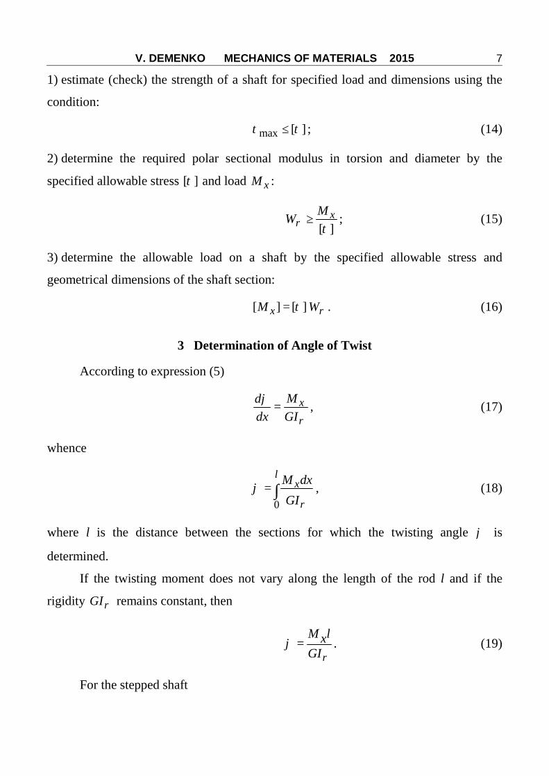
3 Determination of Angle of Twist
According to expression (5)
= xMddx GIρ
ϕ , (17)
whence
0= ∫
lxM dx
GIρϕ , (18)
where l is the distance between the sections for which the twisting angle ϕ is
determined.
If the twisting moment does not vary along the length of the rod l and if the
rigidity GIρ remains constant, then
=M lxGIρ
ϕ . (19)
For the stepped shaft

V. DEMENKO MECHANICS OF MATERIALS 2015
8
1 1= =∑ ∑
= = i
iM ln n x i
i G Iii i ρϕ ϕ . (20)
4 Condition of Rigidity in Torsion
The relative twisting angle ψ can be introduced as follows:
= =M x
l GIρ
ϕψ . (21)
This angle is independent of the shaft length.
Shaft must satisfy the condition of rigidity, i.e. the maximum relative twisting
angle ψ must not exceed the allowable relative twisting angle [ ]ψ :
maxmax [ ]= ≤x
p
MGI
ψ ψ , (22)
where [ ]ψ is the allowable relative angle of twist in radians per meter of the shaft
length.
The allowable relative twisting angle is usually specified in degrees per meter of
length. The formula of shaft rigidity will then have a somewhat different form:
maxmax
180[ ]= ≤x
p
MGI
ψ ψπ
. (23)
Like the condition of strength, the condition of rigidity makes it possible to solve
similar three types of engineering problems.
5 Lines of Principal Stresses
The lines of principal stresses are helical lines. They are located at 45º angle to
the shaft generatrix:
V. DEMENKO MECHANICS OF MATERIALS 2015
9
Fig. 15
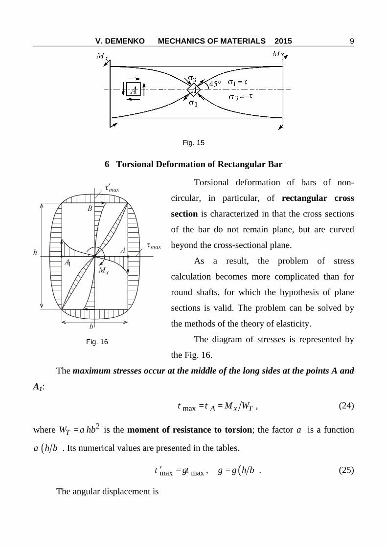
6 Torsional Deformation of Rectangular Bar
Torsional deformation of bars of non-
circular, in particular, of rectangular cross
section is characterized in that the cross sections
of the bar do not remain plane, but are curved
beyond the cross-sectional plane.
As a result, the problem of stress
calculation becomes more complicated than for
round shafts, for which the hypothesis of plane
sections is valid. The problem can be solved by
the methods of the theory of elasticity.
The diagram of stresses is represented by
the Fig. 16.
The maximum stresses occur at the middle of the long sides at the points A and
A1:
max = =A x TM Wτ τ , (24)
where 2=TW hbα is the moment of resistance to torsion; the factor α is a function
( )h bα . Its numerical values are presented in the tables.
max max′ =τ γτ , ( )= h bγ γ . (25)
The angular displacement is
Fig. 16
V. DEMENKO MECHANICS OF MATERIALS 2015
10
= xT
M lGI
ϕ , (26)
where 3=TI hbβ , ( )= h bβ β .
The factors α , γ and β depend on the ratio of the sides h b .
hb
1 1,5 2,0 3,0 4,0 6,0 8,0 10,0 >10
α 0,208 0,231 0,246 0,267 0,282 0,299 0,307 0,313 0,333
β 0,141 0,196 0,229 0,263 0,281 0,299 0,307 0,313 0,333
γ 1 0,859 0,795 0,753 0,745 0,743 0,743 0,743 0,743
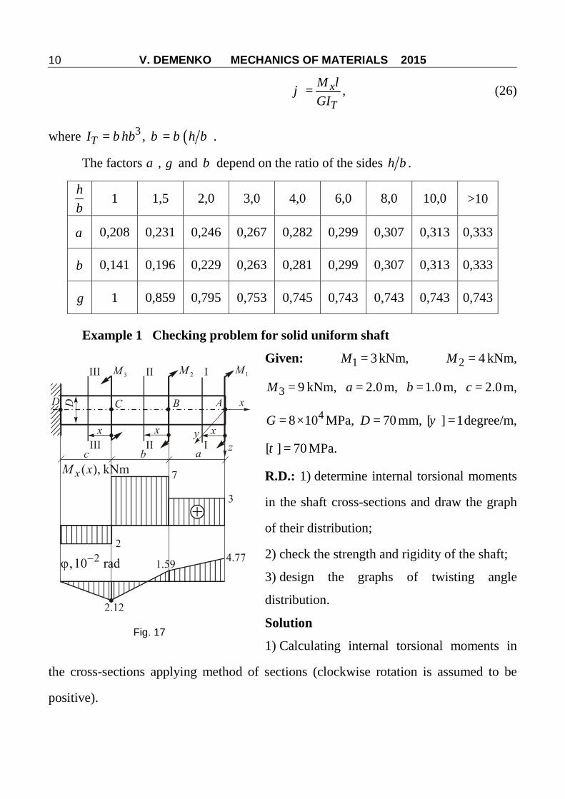
Example 1 Checking problem for solid uniform shaft
Given: 1 3=M kNm, 2 4=M kNm,
3 9=M kNm, 2.0=a m, 1.0=b m, 2.0=c m,
48 10= ×G MPa, 70=D mm, [ ] 1=ψ degree/m,
[ ] 70=τ MPa.
R.D.: 1) determine internal torsional moments
in the shaft cross-sections and draw the graph
of their distribution;
2) check the strength and rigidity of the shaft;
3) design the graphs of twisting angle
distribution.
Solution
1) Calculating internal torsional moments in
the cross-sections applying method of sections (clockwise rotation is assumed to be
positive).
Fig. 17
V. DEMENKO MECHANICS OF MATERIALS 2015
11
I–I 0 2< <x m
( ) 1 3= + = +IxM x M kNm;
II–II 0 1< <x m
( ) 1 2 3 4 7= + + = + =IIxM x M M kNm;
III–III 0 2< <x m
( ) 1 2 3 3 4 9 2= + + − = + − = −IIIxM x M M M kNm.
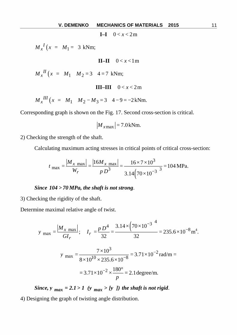
Corresponding graph is shown on the Fig. 17. Second cross-section is critical.
max 7.0=xM kNm.
2) Checking the strength of the shaft.
Calculating maximum acting stresses in critical points of critical cross-section:
( )3
max maxmax 3 33
16 16 7 10 1043.14 70 10−
× ×= = = =
×
x xM MW Dρ
τπ
MPa.
Since 104 70> MPa, the shaft is not strong.
3) Checking the rigidity of the shaft.
Determine maximal relative angle of twist.
maxmax = xM
GIρψ ;
( )4348
3.14 70 10235.6 10
32 32
−−
× ×= = = ×
DIρπ m4.
32
max 10 87 10 3.71 10
8 10 235.6 10−
−×
= = ×× × ×
ψ rad/m =
2 1803.71 10 2.1− °= × × =
πdegree/m.
Since, max max2.1 1 ( [ ])ψ ψ ψ= > > the shaft is not rigid.
4) Designing the graph of twisting angle distribution.
V. DEMENKO MECHANICS OF MATERIALS 2015
12
For this, we will use the formula:
( ) = =xM xx kxGIρ
ϕ ,
i.e. twisting angle formula really is linear function of the shaft length. It is necessary to
calculate twisting angles of C, B, A cross-sections relative immobile D point and
connect corresponding points of ( )xϕ graph by straight lines.
In our case, torsional rigidity
( )4 410 38 10 70 10 188480
32 32−= = × × × =
DGI Gρπ π Nm.
Twisting angle of C-section will be determined by the formula:
( )32
2 10 22.12 10
188480−
− × ××= = = = − ×
IIIx
С СDM с
GIρϕ ϕ rad.
Twisting angle of B-section relative to immobile D-point will be determined by the
formula:
32.12 10− ×= = + = − × + =
IIx
B BD CD BCM b
GIρϕ ϕ ϕ ϕ
32 2(7 10 ) 12.12 10 1.59 10 rad.
188480− −× ×
= − × + = ×
Twisting angle of A-section relative to immobile D-point will be determined by the
formula:
32 23 10 20.0348 1.59 10 4.77 10
188480− −× × ×
= = + = + = × + = ×I
xA AD BD AB
M aGIρ
ϕ ϕ ϕ ϕ rad.
Corresponding graph is shown on the Fig. 17
V. DEMENKO MECHANICS OF MATERIALS 2015
13
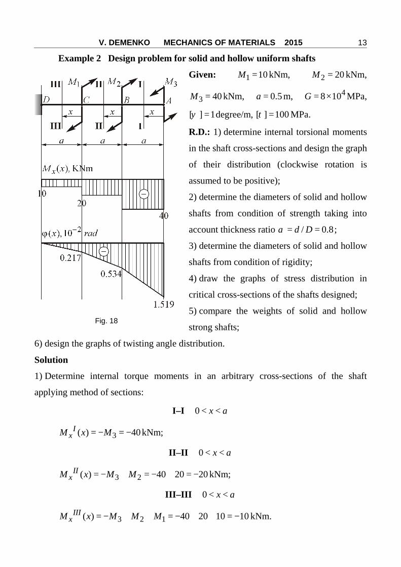
Example 2 Design problem for solid and hollow uniform shafts
Given: 1 10=M kNm, 2 20=M kNm,
3 40=M kNm, 0.5=a m, 48 10= ×G MPa,
[ ] 1=ψ degree/m, [ ] 100=τ MPa.
R.D.: 1) determine internal torsional moments
in the shaft cross-sections and design the graph
of their distribution (clockwise rotation is
assumed to be positive);
2) determine the diameters of solid and hollow
shafts from condition of strength taking into
account thickness ratio / 0.8= =d Dα ;
3) determine the diameters of solid and hollow
shafts from condition of rigidity;
4) draw the graphs of stress distribution in
critical cross-sections of the shafts designed;
5) compare the weights of solid and hollow
strong shafts;
6) design the graphs of twisting angle distribution.
Solution
1) Determine internal torque moments in an arbitrary cross-sections of the shaft
applying method of sections:
I–I 0 < <x a
3( ) 40= − = −IxM x M kNm;
II–II 0 < <x a
3 2( ) 40 20 20= − + = − + = −IIxM x M M kNm;
III–III 0 < <x a
3 2 1( ) 40 20 10 10= − + + = − + + = −IIIxM x M M M kNm.
Fig. 18
V. DEMENKO MECHANICS OF MATERIALS 2015
14
In result, ( ) 40=xM x kNm and I–I section is critical.
2) Calculating the diameters of the shafts from the condition of strength.
a) for solid shaft:
[ ]3
max max 33max 616 16 40 10[ ] 0.127
3.14 100 10× ×
= ≤ → ≥ = =× ×
x xM MD
Wρτ τ
π τm;
b) for hollow shaft in 0.8= =dD
α :
[ ][ ]
3max max 33max 4 4 6 4
16 16 40 10 0.151m,(1 ) (1 ) 3.14 100 10 (1 0.8 )
× ×= ≤ → ≥ = =
− − × × −x xM M
DWρ
τ τα π τ α
0.8 0.151 0.121= × =d m.
3) Calculating the diameters of the shafts from the condition of rigidity.
a) for solid shaft:
maxmax [ ]
180= ≤xM
GIρ
πψ ψ , where [ ]ψ – in degree/m.
Then
[ ]4 3
5max4 6
180 40 10 180 2.86 1032 3.14 8 10 10
−× × ×= ≥ = = ×
× × ×xMDI
Gρπ
π ψm4.
544 32 32 2.86 10 0.131
3.14
−× ×≥ = =
ID ρ
πm.
b) for hollow shaft:
[ ]4
4 5max 180(1 ) 2.86 10
32−×
= − = = ×xMDIGρ
πα
π ψm4,
544 4 4
32 32 2.86 10 0.149(1 ) 3.14(1 0.8 )
−× ×≥ = =
− −
ID ρ
π αm.
0.8 0.149 0.119= × =d m.
V. DEMENKO MECHANICS OF MATERIALS 2015
15
After comparing the results we select for engineering application:
a) solid shaft with the diameter 0.131=D m as larger of two calculated values;
b) hollow shaft with the diameters
0.151=D m, 0.121=d m,
as the larger pair of two calculated ones.
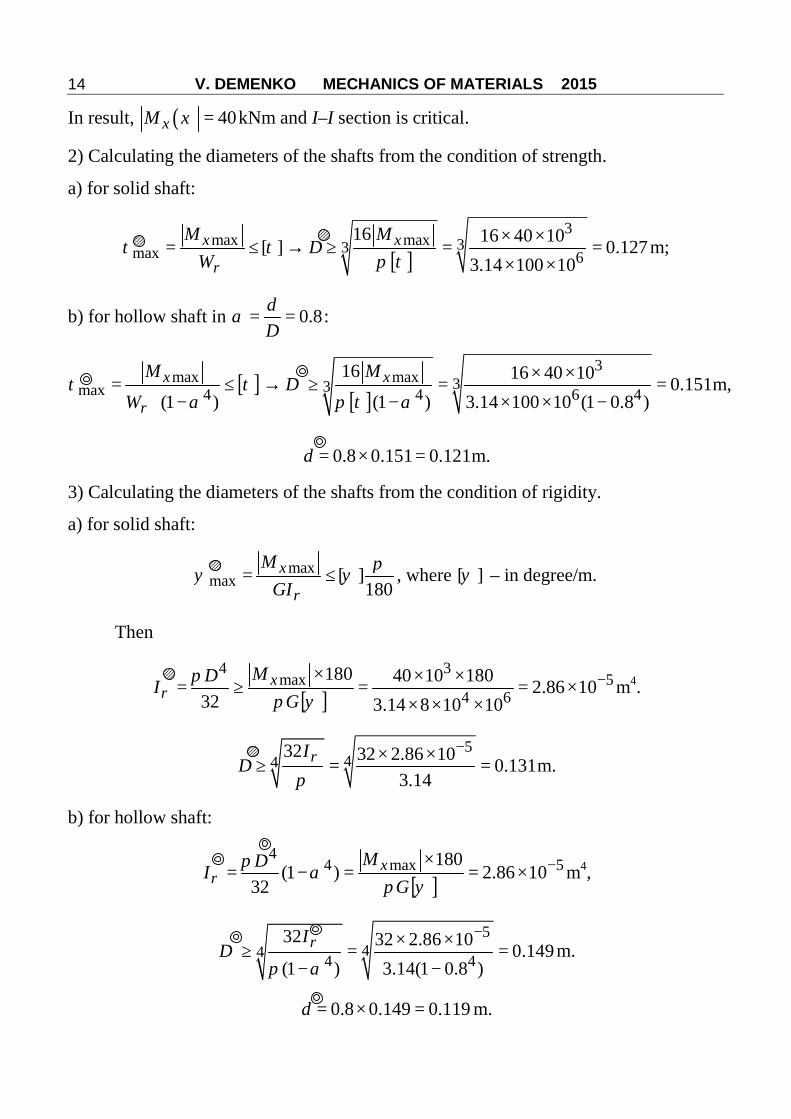
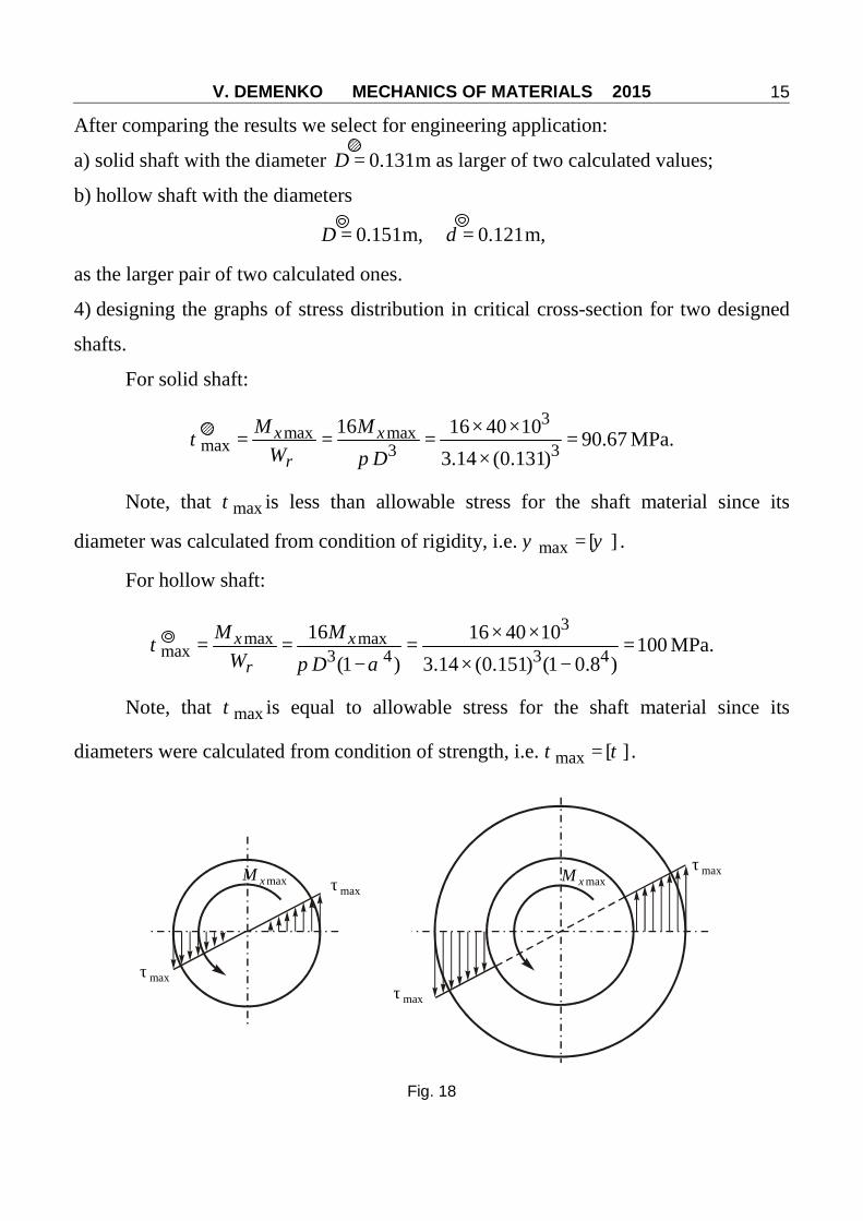
4) designing the graphs of stress distribution in critical cross-section for two designed
shafts.
For solid shaft:
3max max
max 3 316 16 40 10 90.67
3.14 (0.131)× ×
= = = =×
x xM MW Dρ
τπ
MPa.
Note, that maxτ is less than allowable stress for the shaft material since its
diameter was calculated from condition of rigidity, i.e. max [ ]=ψ ψ .
For hollow shaft:
3max max
max 3 4 3 416 16 40 10 100
(1 ) 3.14 (0.151) (1 0.8 )× ×
= = = =− × −
x xM MW Dρ
τπ α
MPa.
Note, that maxτ is equal to allowable stress for the shaft material since its
diameters were calculated from condition of strength, i.e. max [ ]=τ τ .
maxτ
maxτ
maxτ
maxτ
maxxM maxxM
Fig. 18
V. DEMENKO MECHANICS OF MATERIALS 2015
16
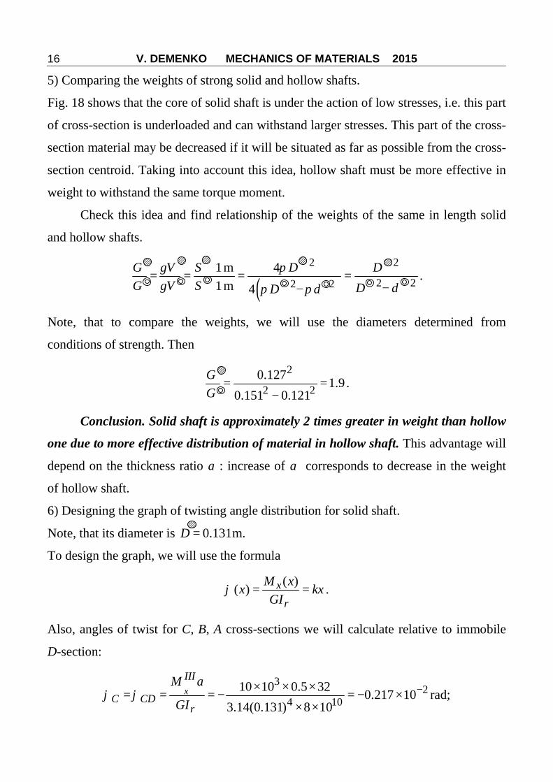
5) Comparing the weights of strong solid and hollow shafts.
Fig. 18 shows that the core of solid shaft is under the action of low stresses, i.e. this part
of cross-section is underloaded and can withstand larger stresses. This part of the cross-
section material may be decreased if it will be situated as far as possible from the cross-
section centroid. Taking into account this idea, hollow shaft must be more effective in
weight to withstand the same torque moment.
Check this idea and find relationship of the weights of the same in length solid
and hollow shafts.
( )2 2
2 22 21m 41m 4
⋅= = = =
⋅ −−
G V S D DG V S D dD d
γ πγ π π
.
Note, that to compare the weights, we will use the diameters determined from
conditions of strength. Then
2
2 20.127 1.9
0.151 0.121= =
−
GG
.
Conclusion. Solid shaft is approximately 2 times greater in weight than hollow
one due to more effective distribution of material in hollow shaft. This advantage will
depend on the thickness ratio α : increase of α corresponds to decrease in the weight
of hollow shaft.
6) Designing the graph of twisting angle distribution for solid shaft.
Note, that its diameter is 0.131=D m.
To design the graph, we will use the formula
( )( ) = =xM xx kxGIρ
ϕ .
Also, angles of twist for C, B, A cross-sections we will calculate relative to immobile
D-section:
32
4 1010 10 0.5 32 0.217 10
3.14(0.131) 8 10−× × ×
= = = − = − ×× ×
xIII
C CDM a
GIρϕ ϕ rad;
V. DEMENKO MECHANICS OF MATERIALS 2015
17
32
4 1020 10 0.5 320.217 10
3.14(0.131) 8 10− × × ×
= = + = + = − × − =× ×
xII
B BD DC CB CDM a
GIρϕ ϕ ϕ ϕ ϕ
2 2 20.217 10 0.434 10 0.651 10− − −= − × − × = − × rad;
32
4 1040 10 0.5 320.651 10
3.14(0.131) 8 10− × × ×
= = + = + = − × − =× ×
Ix
A AD BD BA BDM aGIρ
ϕ ϕ ϕ ϕ ϕ
2 2 20.651 10 0.868 10 1.519 10− − −− × − × = − × rad.
Corresponding graph is shown in Fig. 18.
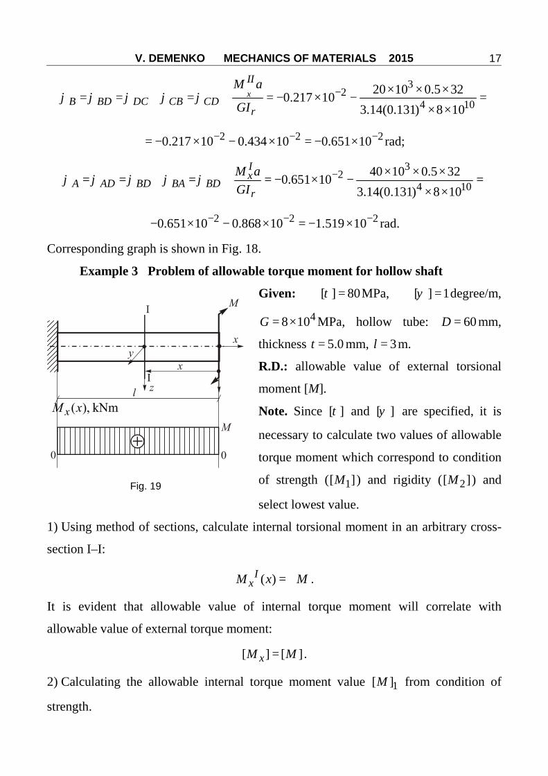
Example 3 Problem of allowable torque moment for hollow shaft
Given: [ ] 80=τ MPa, [ ] 1=ψ degree/m,
48 10= ×G MPa, hollow tube: 60=D mm,
thickness 5.0=t mm, 3=l m.
R.D.: allowable value of external torsional
moment [M].
Note. Since [ ]τ and [ ]ψ are specified, it is
necessary to calculate two values of allowable
torque moment which correspond to condition
of strength ( 1[ ]M ) and rigidity ( 2[ ]M ) and
select lowest value.
1) Using method of sections, calculate internal torsional moment in an arbitrary cross-
section I–I:
( ) = +IxM x M .
It is evident that allowable value of internal torque moment will correlate with
allowable value of external torque moment:
[ ] [ ]=xM M .
2) Calculating the allowable internal torque moment value 1[ ]M from condition of
strength.
Fig. 19
V. DEMENKO MECHANICS OF MATERIALS 2015
18
Since max [ ]= ≤xMWρ
τ τ , then 1[ ] [ ]=xM Wρ τ ; 3
4(1 )16
= −DWρ
πα ;
2 2 60 101 0.8360
− −= = − = =
D t tD D
α ;
2 34 63.14 (60 10 ) (1 0.83 ) 22.25 10
16
−−× ×
= − = ×Wρ m3.
After this, 6 61[ ] 22.25 10 80 10 1.78−= × × × =xM kNm.
3) Calculating the allowable internal torque moment value 2[ ]M from condition of
rigidity.
Since maxmax [ ]= ≤xM
GIρψ ψ , then 2[ ] [ ]=xM GIρ ϕ ;
4 2 44 4 83.14 (6 10 )(1 ) (1 0.83 ) 66.76 10
32 32
−−× ×
= − = − = ×DIρ
πα m4.
Thus, 4 6 82
3.14[ ] 8 10 10 66.76 10 1 0.932180
−= × × × × × × =xM kNm.
In result, [ ] 0.932=xM kNm and [ ] [ ] 0.932= =xM M kNm.
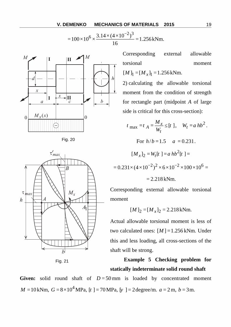
Example 4 Problem of allowable torque moment for composite shaft
Given: combined round rectangle shaft. Round part: 24 10−= ×d m. Rectangle part:
1.5=h b , 24 10−= = ×b d m, 100=τ MPa.
R.D.: allowable value of external torsional moment [M].
Solution
Note, that in both parts of the shaft =xM M (counterclockwise rotation was assumed
as negative).
1) calculating the allowable torsional moment from the condition of strength for solid
round part:
3max 1[ ] [ ] [ ] [ ]
16= ≤ → = × = =x
xM DM WW ρ
ρ
πτ τ τ τ
V. DEMENKO MECHANICS OF MATERIALS 2015
19
2 36 3.14 (4 10 )100 10 1.256
16
−× ×= × × = kNm.
Corresponding external allowable
torsional moment
1 1[ ] [ ] 1.256= =xM M kNm.
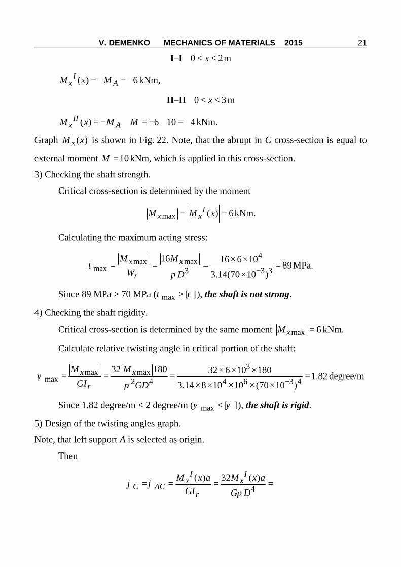
2) calculating the allowable torsional
moment from the condition of strength
for rectangle part (midpoint A of large
side is critical for this cross-section):
max [ ]= = ≤xA
t
MW
τ τ τ , 2=tW hbα .
For / 1.5=h b 0.231=α .
22[ ] [ ] [ ]= = =x tM W hbτ α τ
2 2 2 60.231 (4 10 ) 6 10 100 10− −= × × × × × × =
2.218= kNm.
Corresponding external allowable torsional
moment
2 2[ ] [ ] 2.218= =xM M kNm.
Actual allowable torsional moment is less of
two calculated ones: [ ] 1.256=M kNm. Under
this and less loading, all cross-sections of the
shaft will be strong.
Example 5 Checking problem for
statically indeterminate solid round shaft
Given: solid round shaft of 50=D mm is loaded by concentrated moment
10=M kNm, 48 10= ×G MPa, [ ] 70=τ MPa, [ ] 2=ψ degree/m. 2=a m, 3=b m.
Fig. 20
Fig. 21

V. DEMENKO MECHANICS OF MATERIALS 2015
20
R.D.: Check the strength and rigidity of the
shaft and design the graph of twisting angles.
Note. Strength and rigidity analysis is
impossible without preliminary calculation of
reactive moments AM and BM .
Solution
1) Calculating the reactive moments in
supports AM and BM .
a) Equation of equilibrium is
0= + − =∑ x B AM M M M .
Note, that clockwise rotation was assumed to
be positive.
Since there are two unknown values and
only one equation it is necessary to find complementary equation. It is evident, that all
cross-sections are rotated relative to each other, but two cross-sections A and B are
immobile. This facts allows creating complementary equation as equation of angular
deformations compatibility
0=ABϕ .
It is evident that 0= + =AB AC CBϕ ϕ ϕ or
( )=
Ix
ACM x a
GIρϕ , ( )
=II
xAC
M x bGIρ
ϕ .
Since ( ) = −Ix AM x M ; ( ) = − +II
x AM x M M ,
( ) 0− − += + =A A
ABM M M b
GI GIρ ρϕ .
In result, 310 10 3 6
(2 3)× ×
= = =+ +A
MbMa b
kNm, and static indeterminacy is opened.
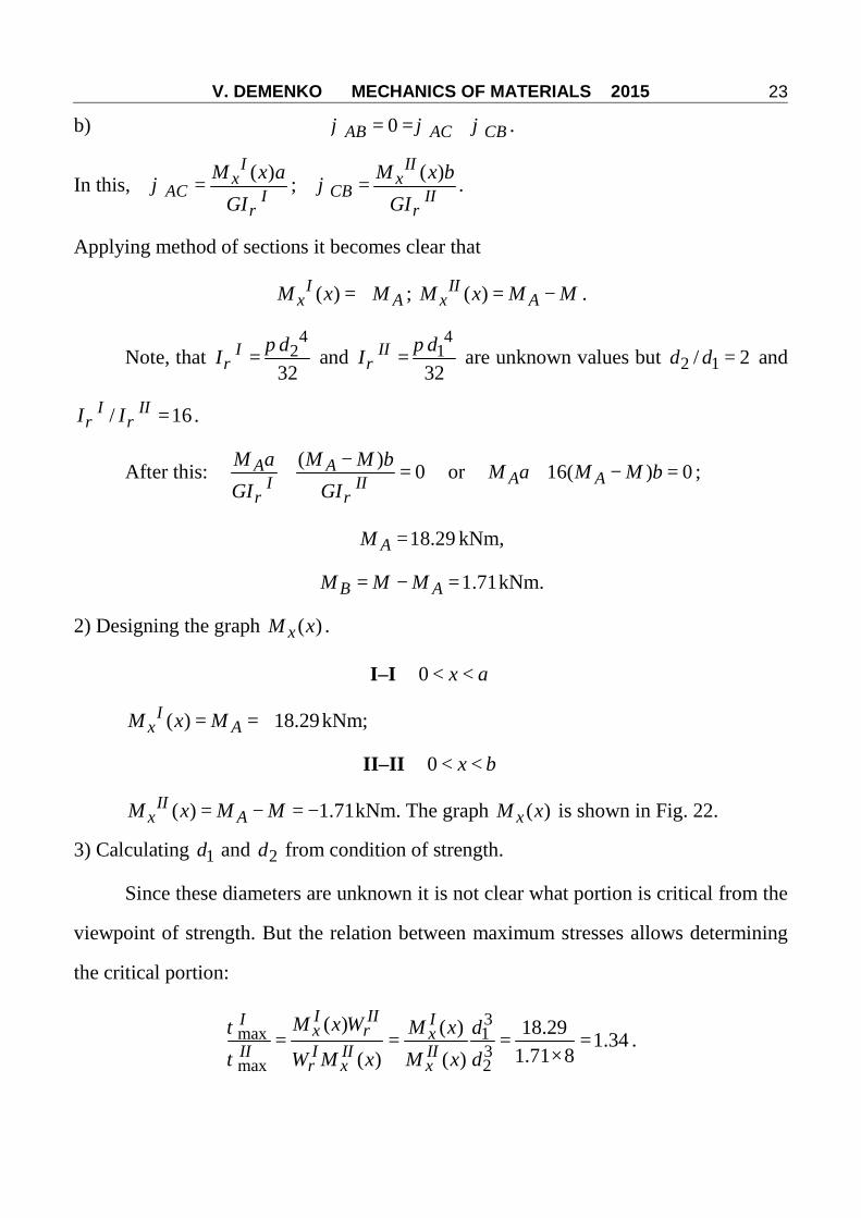
2) Equations of internal torsional moments and corresponding graph ( )xM x .
Fig. 22
V. DEMENKO MECHANICS OF MATERIALS 2015
21
I–I 0 2< <x m
( ) 6= − = −Ix AM x M kNm,
II–II 0 3< <x m
( ) 6 10 4= − + = − + = +IIx AM x M M kNm.
Graph ( )xM x is shown in Fig. 22. Note, that the abrupt in C cross-section is equal to
external moment 10=M kNm, which is applied in this cross-section.
3) Checking the shaft strength.
Critical cross-section is determined by the moment
max ( ) 6= =Ix xM M x kNm.
Calculating the maximum acting stress:
4max max
max 3 3 316 16 6 10 89
3.14(70 10 )−× ×
= = = =×
x xM MW Dρ
τπ
MPa.
Since 89 MPa > 70 MPa ( max [ ]>τ τ ), the shaft is not strong.
4) Checking the shaft rigidity.
Critical cross-section is determined by the same moment max 6=xM kNm.
Calculate relative twisting angle in critical portion of the shaft:
3max max
max 2 4 4 6 3 432 180 32 6 10 180 1.82
3.14 8 10 10 (70 10 )−× × ×
= = = =× × × × ×
x xM MGI GDρ
ψπ
degree/m
Since 1.82 degree/m < 2 degree/m ( max [ ]<ψ ψ ), the shaft is rigid.
5) Design of the twisting angles graph.
Note, that left support A is selected as origin.
Then
4( ) 32 ( )
= = = =I I
x xC AC
M x a M x aGI G Dρ
ϕ ϕπ

V. DEMENKO MECHANICS OF MATERIALS 2015
22
32
4 6 2 432( 6 10 ) 2 6.37 10
8 10 10 3.14 (7 10 )−
−− × ×
= = − ×× × × × ×
rad
2 24
( ) 32 ( )6.37 10 6.37 10− −= = + = − × + = − × + =II II
x xB AB AC CB
M x b M x bGI G Dρ
ϕ ϕ ϕ ϕπ
32 2 2
4 6 2 432 4 10 36.37 10 6.37 10 6.37 10 0
8 10 10 3.14 (7 10 )− − −
−× × ×
= − × + = − × + × =× × × × ×
.
Note, that this result may be predicted since B cross-section is rigidly fixed.
The ( )xϕ graph is shown in Fig. 22.
Example 6 Design problem for statically indeterminate solid and hollow
nonuniform shafts
Given: round stepped steel shaft is
rigidly fixed in A and B points and
loaded by external torsional moment
20=M kNm. Also, [ ] 100=τ MPa,
[ ] 1=ψ degree/m, 48 10= ×G MPa,
0,6=a m, 0,4=b m, 2 1/ 2=d d .
R.D.: calculate 1d and 2d from
conditions of strength and rigidity.
Solution
Note, that calculation of internal
torsional moments is impossible without
preliminary calculating the reactive moments AM and BM .
1) Calculating the reactive moments AM and BM .
a) from equation of equilibrium 0=∑ xM :
0= = + −∑ x A BM M M M .
It is evident that two unknown values AM and BM can not be determined from one
equation. Complementary compatibility equation is:
Fig. 23
V. DEMENKO MECHANICS OF MATERIALS 2015
23
b) 0= = +AB AC CBϕ ϕ ϕ .
In this, ( )=
Ix
AC IM x a
GIρϕ ; ( )
=II
xCB II
M x bGIρ
ϕ .
Applying method of sections it becomes clear that
( ) = +Ix AM x M ; ( ) = −II
x AM x M M .
Note, that 4
232
=I dIρπ and
41
32=II dIρ
π are unknown values but 2 1/ 2=d d and
/ 16=I III Iρ ρ .
After this: ( ) 0−+ =A A
I IIM a M M bGI GIρ ρ
or 16( ) 0+ − =A AM a M M b ;
18.29=AM kNm,
1.71= − =B AM M M kNm.
2) Designing the graph ( )xM x .
I–I 0 < <x a
( ) 18.29= = +Ix AM x M kNm;
II–II 0 < <x b
( ) 1.71= − = −IIx AM x M M kNm. The graph ( )xM x is shown in Fig. 22.
3) Calculating 1d and 2d from condition of strength.
Since these diameters are unknown it is not clear what portion is critical from the
viewpoint of strength. But the relation between maximum stresses allows determining
the critical portion:
3max 1
3max 2
( ) ( ) 18.29 1.341.71 8( ) ( )
= = = =×
I III Ix xII I II II
x x
M x W M x dW M x M x d
ρ
ρ
τ
τ.
V. DEMENKO MECHANICS OF MATERIALS 2015
24
Since max max>I IIτ τ , first portion will be critical from the viewpoint of strength
and condition of strength becomes
max max( ) [ ]= = ≤
II x
IM x
Wρτ τ τ , and
[ ]3
2332 616 ( ) 16 18.29 10 9.77 10
3.14 100 10−× ×
≥ = = ×× ×
IxM xd
π τm.
221 4.89 10
2−= = ×
dd m.
4) Calculating 1d і 2d from condition of rigidity. To find actually critical portion let us
calculate relation between relative twisting angles:
4241
( ) ( ) 1.71 16 1.518.29( ) ( )
×= = = =
III IIIIx x
I II I Ix x
GIM x M x dGI M x M x d
ρ
ρ
ψ
ψ.
Since <II Iψ ψ , the second portion will be critical from the viewpoint of rigidity.
Corresponding condition of rigidity is: max( ) [ ]= = ≤
III x
IIM xGIρ
ψ ψ ψ , and
[ ]3
2441 2 4 632 ( ) 180 32 1.71 10 180 5.94 10
3.14 8 10 10 1−× × ×
≥ × = = ×× × × ×
IIxM xd
Gπ ψ πm.
22 12 11.8 10−= = ×d d m.
Final selection is 21 5.94 10−= ×d m and 2
2 11.8 10−= ×d m. This pair satisfies the
conditions of strength and rigidity.