a case study of strengthening of deficient rc building
TRANSCRIPT

COMPDYN 2011 III ECCOMAS Thematic Conference on
Computational Methods in Structural Dynamics and Earthquake Engineering M. Papadrakakis, M. Fragiadakis, V. Plevris (eds.)
Corfu, Greece, 26–28 May 2011
A CASE STUDY OF STRENGTHENING OF DEFICIENT RC BUILDING WITH INTERNAL STEEL FRAME
R. Ozcelik1, B. Binici2
1 Middle East Technical University Middle East Technical University, Department of Civil Engineering, Turkey
2Middle East Technical University Middle East Technical University, Department of Civil Engineering, Turkey
Keywords: Internal Steel Frame, Seismic Retrofit, RC Frames.
Abstract. This study examines the strengthening of existing deficient reinforced concrete (RC) building by using internal steel frame (ISF). Test results indicated that ISF increased the lat-eral strength, ductility and energy dissipation capacity of the deficient RC building signifi-cantly. The test results were compared with simulations to observe performance levels. A case study building was analyzed to demonstrate the performance of an ISF retrofitted deficient RC building by using an analytical model calibrated with test results. The analyzed building was located at Marmara region in Turkey where the region most susceptible to severe earth-quakes. The performance based evaluation with respect to Turkish Earthquake Code indi-cated that this building should be strengthened under Duzce ground motion demand. After strengthening by using ISF, the building was within the life safety performance level which is the performance level that needs to be satisfied for residential buildings. The modeling strat-egy and construction details of the ISF are also presented in this study.

R. Ozcelik, B. Binici
2
1 INTRODUCTION
Poor performance of reinforced concrete (RC) buildings was demonstrated dramatically in recent earthquakes (Northridge 1994, Kobe 1994, Kocaeli 1999, Taiwan 2003, India 2001) due to insufficient lateral load resisting system. Common deficiencies of RC buildings in many of the developing countries owe either to lack of knowledge about seismic risk or to malpractice and insufficient quality control during construction. The poor quality control re-sults in low strength concrete (in the range of 8 to 15 MPa), insufficient spacing of transverse confining reinforcement in beams, columns and joints, and insufficient splice length at col-umn critical regions that may result in excessive bond slip of plain longitudinal reinforcement. To reduce the effect of these deficiencies on existing structures, seismic retrofitting tech-niques should be developed. Furthermore, application of the seismic retrofitting techniques should be encouraged to be used by the authority and people live in high seismic regions.
There are many strengthened techniques namely adding structural walls [1-4], steel braces [5-13], FRP diagonal braces integrated in the infill walls [14-16], precast-shear walls that fit perfectly into the existing frame [17], steel frames attached externally to the perimeter of the existing frame [17], and steel frames attached within the frame without using anchors [18]. Although the most commonly used strengthened technique is adding structural wall, this technique requires interrupting building use for a substantial period of time and may conflict with architectural requirements.
The literature review indicated that there is urgent need to develop a rapid, safe and practi-cal strengthening technique. The internal steel frames (ISFs) which are one of the candidate retrofitting techniques are installed within bays of the deficient RC frames. The ISF is in-tended to easily accommodate wall openings for architectural requirements. In this study, firstly an experimental test frame with and without ISF was examined and then the analytical study was conducted to calibrate test frame with ISF. By using analytical results, the perform-ance level of the frame with ISF was performed with respect to Turkish Earthquake Code (TEC 2007) [19]. Based on calibration of the test frame with ISF, an existing five story resi-dential building was strengthened with ISF and the performance of such building was evalu-ated by using procedure suggested by TEC 2007 [19]. Duzce earthquake record was utilized in the nonlinear time history analysis to determine the performance points of the building be-fore and after retrofitting. This study also explains the installation procedure of the ISF to the RC frame.
2 TEST FRAME AND ISF INSTALLATION PRODECURE
Two, one bay-by-one story, portal RC frames were examined to determine cyclic perform-ance of the ISF. First test specimen SP1 was reference frame tested without any retrofitting while second specimen SP2 was tested after implementing ISF in the RC frame. Although comprehensive information about the test frames is available in elsewhere [20], a summary was introduced in this study. As shown in Figure 1, the center-to-center span length was 1400 mm and the column height was 1000 mm. The dimensions of the columns were 100 mm × 150 mm with four 8-mm diameter longitudinal reinforcement plain bars resulting in about 1.33 % longitudinal reinforcement ratio. 4 mm diameter plain bars were used for stirrups. TEC 2007 requires stirrups to be anchor using 135 degree hooks however 90 degree hooks were used for all columns and beam to simulate the detailing deficiency of the Turkish con-struction practice before the establishment of the modern seismic codes. To simulate the in-sufficient confinement details of the columns, the stirrup spacing of the columns was equal to the smaller dimension of the column section (100 mm). The 100 mm × 150 mm beam was cast with a 450-mm wide, 55-mm thick slab. A 70-mm transverse reinforcement spacing was

R. Ozcelik, B. Binici
3
used for the beams. The RC beam-column joint had only one column stirrup extending into the joint. The yield strength of the 4-mm and 8-mm diameter reinforcement bars was deter-mined as 270 and 330 MPa, respectively. The target 28-day cylinder compression strength was 8 MPa to simulate the existing deficient structures with low concrete strength determined in field investigations [21-23].
A constant gravity load of 62 kN was applied by placing steel blocks on the RC frame (see Figure 1(c)). This gravity resulted in the axial load ratio (i.e. ratio of gravity load to axial load carrying capacity) for the RC column was roughly 20% for all specimens. Cyclic lateral load-ing was introduced by controlling the drift ratio (DR) as in Figure 1 (d).
Figure 1: a) Analyzed building floor view, b) Analyzed 4-story frame, c) Beam and column section.
The ISF was composed of rigidly connected beams and columns. The ISFs were imple-mented after constant gravity load was applied on the RC frame to simulate actual retrofit conditions. The application procedure was as flows; firstly, anchor holes were drilled into the
1000mm150mm
150mm
450mmFoundation
Floor
1400mm
BB
A
A
Column
Beam
450mm
400mm
100mm
450mm
55mm
100mm
150mm
Longitudinal bar; 4-φ8 and 4-φ4 , Stirrup; φ8/70mm
150mm
100mm
Longitudinal bar; 4-φ8 , Stirrup; φ8/100mm
a)
b)
66
140 1503
100
150
3
80mm
Section A-A
Section B-B
B B
A
A
Section A-A
Section B-B
c) Steel Blocks
Reaction Wall
Floor
RC Frame
Loading Program
0.0
0 5.1
5-5
.15
5.1
5-5
.15
10.3
0-1
0.3
010
.30
-10
.30
15.
45
-15
.45
15.
45
-15
.45
20.6
0-2
0.6
020
.60
-20
.60
30.9
0-3
0.9
030
.90
-30
.90
41.2
0-4
1.2
041
.20
-41
.20
51.5
0-5
1.5
0
-5.5-5
-4.5-4
-3.5-3
-2.5-2
-1.5-1
-0.50
0.51
1.52
2.53
3.54
4.55
5.5
Drif
t, %
-60
-50
-40
-30
-20
-10
0
10
20
30
40
50
60
Def
lect
ion
, mm
d)
I-80
I-140

R. Ozcelik, B. Binici
4
column face and bottom side of the RC beams. Than, these wholes were cleaned up by air blowing, brushing and air blowing (Figure 1 (b)). Next, epoxy primer was injected into these holes and the anchor rods were inserted and left for curing. In the second stage, a thin layer (about 3 mm) repair putty was applied on the RC member on all surfaces that contact the ISF (Figure 1). Before the epoxy cured, the anchor rods were tightened to fasten the individual steel members to the RC frame. Finally, the steel beams were welded to the steel column. The diameter of the anchor rods and holes were 6 mm and 8 mm, respectively. The anchors were embedded 120 mm into the RC beam and columns.
2.1 TEST RESULTS
Figure 2 shows the hysteretic response obtained from both specimens [20]. Specimens SP1 and SP2 developed a lateral stiffness (the peak positive and negative loading points during the first cycle (± 0.5% DR)) of 2.48 and 12.68 kN/mm, respectively. The lateral strength of the specimens SP1 and SP2 were 13.7 and 118.9 kN.
Figure 2: a) Cyclic response of the reference frame, b) Cyclic response of the strengthened frame, c) Envelope response of the frames.
-140
-105
-70
-35
0
35
70
105
140
-0.08 -0.06 -0.04 -0.02 0 0.02 0.04 0.06 0.08Drift Ratio
Late
ral F
orc
e (
kN)
-20
-15
-10
-5
0
5
10
15
20
-0.08 -0.06 -0.04 -0.02 0 0.02 0.04 0.06 0.08Drift Ratio
Lat
eral
Fo
rce
(kN
)
-140
-105
-70
-35
0
35
70
105
140
-0.08 -0.06 -0.04 -0.02 0.00 0.02 0.04 0.06 0.08Drift Ratio (%)
Late
ral F
orce
(kN
)
SP1SP2
SP1
SP2
a)
b)
c)

R. Ozcelik, B. Binici
5
Plastic hinges were first observed at the bases for the reference frame (specimen SP1). A plas-tic mechanism was formed at a drift ratio DR slightly higher than ± 2%. Upon further lateral displacements, pinching behavior and severe stiffness degradation was observed. Specimen SP2 was designed to develop composite action in the beam and two columns. Cracks in the concrete widened during each loading excursion that produced tension in the concrete portion of the composite section. The specimen SP2 failed due to fracture of the welded beam-to-column connection that initiated at ± 3 % DR. These test results indicated that the ISF retrofit-ting increased the lateral strength, stiffness and energy dissipation capacity of the deficient RC frame significantly.
2.2 ANALYTICAL STUDY OF THE TEST FRAME
The test frame, specimen SP2, was analyzed by using nonlinear static pushover procedure in order to determine plastic rotations at the ends of the beam and columns. Firstly, moment rotation relations were derived from sections indicated in Figure 1(b). The composite column and beam members had two moment curvature relation whether bending directions is positive or negative. When the composite section was under positive bending, the steel member (I-80 for beam and I140 for column) was under tension but the concrete was under compression. At the negative bending direction, this case was vise verse. Hence, two different moment curva-ture relations were developed for both composite column and beam. The moment curvature relation was converted into moment rotation relation. The plastic hinge length was assumed as half of the section height (TEC 2007).
Mander confined concrete model was used for columns and beam [24]. Longitudinal bar buckling was modeled by employing the backbone curve of Dhakal and Maekawa [25]. P-∆ effect was incorporated into the analytical model. SAP2000 [26] was used for the nonlinear static analysis. The analytical model was designed by using exact section dimensions and ma-terial properties (Figure 3).
Figure 3: Analytical model of the specimen SP2.
0
10
20
30
40
0.00 0.05 0.10 0.15Rotation
Mo
men
t (kN
m)
0
10
20
30
40
50
0.00 0.01 0.02 0.03 0.04Rotation
Mo
men
t (kN
m)
0
10
20
30
40
50
0.00 0.01 0.02 0.03 0.04Rotation
Mo
men
t (kN
m)
0
10
20
30
40
0.00 0.05 0.10 0.15Rotation
Mo
men
t (kN
m)
-40
-30
-20
-10
0
10
20
-0.20 -0.10 0.00 0.10 0.20Rotation
Mo
men
t (kN
m)

R. Ozcelik, B. Binici
6
In the TEC-2007, the moment rotation relation can be designed as elastic perfectly plastic behavior. Hence, after yielding, no hardening was used to model the moment rotation behav-ior (Figure 3). The performance of the member in the procedure suggested in TEC 2007 de-pends on the reinforcement bar and concrete strain (Figure 4). The following equations were defined for three performance levels in TEC-2007; immediate occupancy (IO), life safety (LS) and collapse prevention (CP) performance levels. IO performance level; ( ) 0035.0=IOcuε
( ) 010.0=IOsε
LS performance level; ( ) ( ) 0135.001.00035.0 ≤+= smsLScg ρρε
( ) 040.0=IOsε
CP performance level; ( ) ( ) 018.0014.0004.0 ≤+= smsCPcg ρρε
( ) 060.0=CPsε
Where, εcu; concrete strain at the top fiber εcg; concrete strain at the top fiber of the confined concrete εs; Reinforcement bar strain ρs; available volumetric ratio of the stirrup of the member ρsm; volumetric ratio of the stirrup of the member calculated by utilizing the TEC-2007
Figure 4: Strain at the cross section of the RC member.
Figure 5 indicates the static pushover curve of the test frame (specimen SP2). This figure also indicated the performance of the columns and beam in term of drift ratio. IO, LS and CP were determined by the method suggested in TEC 2007. Each performance levels indicated in Figure 5 exceeded the suggested strain limits at the bottom and top of the columns. Further-more, at the end of each performance levels, the damage observed during the test are also seen in Figure 5. The interstory drift ratio (IDR) limits suggested in TEC 2007 are marked on this figure at 1, 3 and 4% DR. The average DR of the each three performance levels are about 1.0, 2.5 and 3.5 %, respectively.
cgεcuε
sε

R. Ozcelik, B. Binici
7
Figure 5: Analytical result of the test frame (specimen SP2).
0
30
60
90
120
150
0.00 0.01 0.02 0.03 0.04 0.05 0.06 0.07Drift Ratio
Lat
eral
For
ce (
kN)
ExperimentSP2Analytical(SAP2000)
IO LS
CP
A B
C
D
LS, T
EC
200
7
IO, T
EC
200
7
CP
, TR
C 2
007
A
B
C
D
A; Crack iniation, B; Fracture initiation of the steel beam, C; Concrete spalling at the bottom of the column, D; Base hinge mechanism and lateral displacement at 5% DR.

R. Ozcelik, B. Binici
8
3 CASE STUDY
In this section, the performance based design of existing five story RC building located in the Istanbul is presented. The building is a reinforced concrete frame structure with rigid shearwall surrounding the basement (Figure 6). Within this study, a performance
Figure 6: Five story building a) Plan view, b) column and beam dimensions, c) front view of the building, e) analytical model of the building (SAP2000).
Column C1 Long. ; 4φ14
Trans. ; φ10/230
Column C2 Long. ; 6φ14
Trans. ; φ10/220 Beam 150x500 Long. ; 3φ12
Trans. ; φ8/220
2.85m
-3.0m
0.0m
5.7m
8.75m
11.4m
14.2m
Column C3 Long. ; 4φ14
Trans. ; φ10/240
Column C4 Long. ; 4φ14
Trans. ; φ8/250
1 2 3 4 5
67
89
101
1
12
131415
16
A
1
B C D
2
3
4
5
6
1
2
3
4
5
6
A B C D
C2 C2
C2 C2
C1
C1
C3
C3 C3
C3
C4
C4
a) b)
c) d) X direction
R. Ozcelik, B. Binici
9
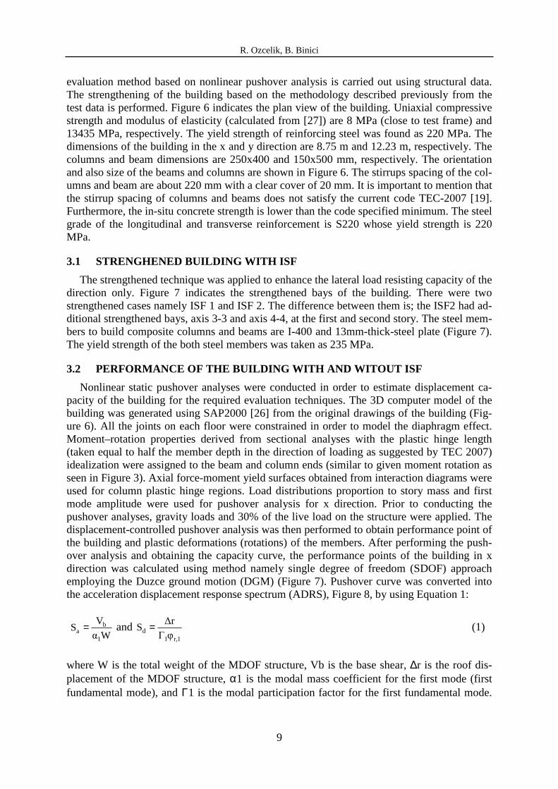
evaluation method based on nonlinear pushover analysis is carried out using structural data. The strengthening of the building based on the methodology described previously from the test data is performed. Figure 6 indicates the plan view of the building. Uniaxial compressive strength and modulus of elasticity (calculated from [27]) are 8 MPa (close to test frame) and 13435 MPa, respectively. The yield strength of reinforcing steel was found as 220 MPa. The dimensions of the building in the x and y direction are 8.75 m and 12.23 m, respectively. The columns and beam dimensions are 250x400 and 150x500 mm, respectively. The orientation and also size of the beams and columns are shown in Figure 6. The stirrups spacing of the col-umns and beam are about 220 mm with a clear cover of 20 mm. It is important to mention that the stirrup spacing of columns and beams does not satisfy the current code TEC-2007 [19]. Furthermore, the in-situ concrete strength is lower than the code specified minimum. The steel grade of the longitudinal and transverse reinforcement is S220 whose yield strength is 220 MPa.
3.1 STRENGHENED BUILDING WITH ISF
The strengthened technique was applied to enhance the lateral load resisting capacity of the direction only. Figure 7 indicates the strengthened bays of the building. There were two strengthened cases namely ISF 1 and ISF 2. The difference between them is; the ISF2 had ad-ditional strengthened bays, axis 3-3 and axis 4-4, at the first and second story. The steel mem-bers to build composite columns and beams are I-400 and 13mm-thick-steel plate (Figure 7). The yield strength of the both steel members was taken as 235 MPa.
3.2 PERFORMANCE OF THE BUILDING WITH AND WITOUT ISF
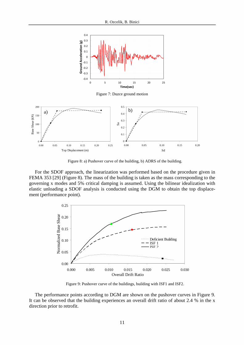
Nonlinear static pushover analyses were conducted in order to estimate displacement ca-pacity of the building for the required evaluation techniques. The 3D computer model of the building was generated using SAP2000 [26] from the original drawings of the building (Fig-ure 6). All the joints on each floor were constrained in order to model the diaphragm effect. Moment–rotation properties derived from sectional analyses with the plastic hinge length (taken equal to half the member depth in the direction of loading as suggested by TEC 2007) idealization were assigned to the beam and column ends (similar to given moment rotation as seen in Figure 3). Axial force-moment yield surfaces obtained from interaction diagrams were used for column plastic hinge regions. Load distributions proportion to story mass and first mode amplitude were used for pushover analysis for x direction. Prior to conducting the pushover analyses, gravity loads and 30% of the live load on the structure were applied. The displacement-controlled pushover analysis was then performed to obtain performance point of the building and plastic deformations (rotations) of the members. After performing the push-over analysis and obtaining the capacity curve, the performance points of the building in x direction was calculated using method namely single degree of freedom (SDOF) approach employing the Duzce ground motion (DGM) (Figure 7). Pushover curve was converted into the acceleration displacement response spectrum (ADRS), Figure 8, by using Equation 1:
Wα
VS
1
ba = and
1r,1d φΓ
∆rS = (1)
where W is the total weight of the MDOF structure, Vb is the base shear, ∆r is the roof dis-placement of the MDOF structure, α1 is the modal mass coefficient for the first mode (first fundamental mode), and Γ1 is the modal participation factor for the first fundamental mode.

R. Ozcelik, B. Binici
10
φr,1 is the amplitude of the first fundamental mode at the roof, Sa is spectral acceleration, and Sd is the spectral displacement.
Figure 7: a) and b) Strengthened building with ISF1 and ISF2, c) frame view of the axis 2-2, d) Section of the composite members.
A
1
B C D
2
3
4
5
6
1
2
3
4
5
6
A B C D
A
1
B C D
2
3
4
5
6
1
2
3
4
5
6
A B C D
1. and 2. story (only)
1. and 2. story (only)
A-A section B-B section
C-C section
C C B B
A
A
2-2 Axis
2-2 Axis
a) ISF 1 b) ISF 2
Steel Plate (13x150mm)
I-400
I-400
c) d)
R. Ozcelik, B. Binici
11
-0.4
-0.3
-0.2
-0.1
0
0.1
0.2
0.3
0.4
0 5 10 15 20 25G
rou
nd
Acc
ele
rati
on
(g
)
Time(sec) Figure 7: Duzce ground motion
Figure 8: a) Pushover curve of the building, b) ADRS of the building.
For the SDOF approach, the linearization was performed based on the procedure given in FEMA 353 [29] (Figure 8). The mass of the building is taken as the mass corresponding to the governing x modes and 5% critical damping is assumed. Using the bilinear idealization with elastic unloading a SDOF analysis is conducted using the DGM to obtain the top displace-ment (performance point).
0.00
0.05
0.10
0.15
0.20
0.25
0.000 0.005 0.010 0.015 0.020 0.025 0.030Overall Drift Ratio
No
rmal
ized
Bas
e S
hea
r
Deficient BuildingISF 1ISF 2
Figure 9: Pushover curve of the buildings, building with ISF1 and ISF2.
The performance points according to DGM are shown on the pushover curves in Figure 9. It can be observed that the building experiences an overall drift ratio of about 2.4 % in the x direction prior to retrofit.
0
50
100
150
200
0.00 0.05 0.10 0.15 0.20 0.25
Top Displacement (m)
Bas
e S
hea
r (k
N)
a)
0
0.1
0.2
0.3
0.4
0.5
0.00 0.05 0.10 0.15 0.20
Sd
Sa
b)

R. Ozcelik, B. Binici
12
A member by member evaluation is then performed to determine the damage level of the members. The number of columns and beams at different performance levels are presented in Table 1. This evaluation indicated that 100% and 36% of the first story columns and beams of the deficient building with any ISFs were at the total collapse (TC) performance level for x directions, respectively. This results indicates that this deficient building needs to be retrofit-ted.
Upon retrofitting, the number of the columns which were in the TC performance level de-creased. Although 33% of the first story columns of the building implemented ISF 1 was within the TC performance level, this condition did not satisfy the performance level of the residential building suggested in TEC 2007. Finally, the desired performance level of the de-ficient building retrofitted with ISF2 was obtained by increasing numbers of retrofitted bays.
Deficient ISF 1 ISF 2 Deficient ISF 1 ISF 2 Deficient ISF 1 ISF 2 Deficient ISF 1 ISF 2 Deficient ISF 1 ISF 2IO 0 4 10 1 11 12 5 12 12 12 12 12 12 12 11LS 0 3 2 4 0 0 6 0 0 0 0 0 0 0 1CP 0 1 0 3 0 0 1 0 0 0 0 0 0 0 0
Total Collapse 12 4 0 4 1 0 0 0 0 0 0 0 0 0 0
Deficient ISF 1 ISF 2 Deficient ISF 1 ISF 2 Deficient ISF 1 ISF 2 Deficient ISF 1 ISF 2 Deficient ISF 1 ISF 2IO 12 16 18 16 19 21 17 19 18 23 19 19 24 22 24LS 2 5 4 1 4 3 7 5 6 1 5 5 0 2 0CP 0 1 0 5 1 0 0 0 0 0 0 0 0 0 0
Total Collapse 8 0 0 2 0 0 0 0 0 0 0 0 0 0 0
1. story 2. story 3. story 4. story 5. story
4. story 5. story
Beam Performance Levels
1. storyColumn Performance Levels
2. story 3. story
Table 1: Performance levels of the members.
Figure 10: IDR of the building at the performance points.
The IDR profiles for x directions obtained from pushover analysis at performance points of DGM are shown in Figure 10. It can be observed that highest IDR, which was about 4.7 % in
0
1
2
3
4
5
0 1 2 3 4 5Drift Ratio (%)
Sto
ry N
umbe
r
DeficientISF 1ISF 2
IO, TEC 2007 LS, TEC 2007 CP, TEC 2007

R. Ozcelik, B. Binici
13
the x direction, occurred in the first story level of the building without any ISF retrofit. Upon retrofit the IDR reduced to about 1.4% for the x directions. It should be noted that the ob-served drift ratio is in good agreement with those limits proposed in the TEC 2007 (Figure 10). This result shows that the ISF retrofit scheme was successful in controlling drift deformations and reducing the demands in the columns. As a results, the ISF retrofit design presented above was found to be successful in LS performance level of the building by reducing the de-formation demands on the RC columns and controlling the drift deformations. In addition, above results clearly indicates that a retrofit technique needs to increase lateral stiffness and strength aside from increasing global ductility capacity (if any member base retrofitting tech-nique is not used) when ductility capacity of the existing columns and beams are insufficient.
4 CONCLUSION
The test results indicated that the ISF increased the lateral strength, stiffness and energy dissipation capacity of the deficient RC frames. The analytical study of the test frame simu-lated the behavior of the test frame successfully. The test frame load-deformation and damage observed during the test was correlated by the proposed performance levels suggested in TEC 2007. It was observed that the performance levels defined in TEC 2007 can be utilized con-servatively to evaluate the frame retrofitted with ISF. Based on the data gained from the test and analytical results of the test frame, a case study consisted of a real existing residential building before and after ISF retrofit was evaluated by utilizing procedures suggested by the TEC 2007 under imposed DGM demand. It was observed that although seismically deficient five story RC building did not satisfy the performance levels of a residential building accep-tance criterion with respect to TEC 20007, it was adequate after retrofitting with ISF. As a result, the ISF can be considered as a rapid, safe and practical retrofitting technique.
5 AKNOWLWEDGE
The research discussed in this paper was conducted at Middle East Technical University (METU)-Structural Mechanics Laboratory. Funding provided by TÜBİTAK (project no: 106M493) is greatly appreciated.
REFERENCES
[1] E. Canbay, U. Ersoy, G. Ozcebe. Contribution of reinforced concrete infills to seismic behavior of structural systems. Structural Journal, ACI, 100(5):637-643, 2003.
[2] M.O. Sonuvar, G. Ozcebe, U. Ersoy. Rehabilitation of reinforced concrete frames with reinforced concrete infills. Structural Journal, ACI, 101(4):494-500, 2004.
[3] S. Altin, U. Ersoy, T. Tankut. Hysteretic response of reinforced-concrete infilled frames. J Struct Engrg ASCE, 118(8):2133-2150, 1992.
[4] M.B.D Hueste, JW Bia. Seismic retrofit of a reinforced concrete flat-slab structure: Part I —seismic performance evaluation. Eng Struct, 29(6):1165–1177, 2006.
[5] M. Badoux, JO Jirsa. Steel bracing of RC frames for seismic retrofitting. J Struct. Engrg ASCE, 116(1):55-74, 1990.
[6] A. Ghobarah, H. Abou-Elfath, Rehabilitation of a reinforced concrete frame using ec-centric steel bracing. Eng Struct, 23(7):745-755, 2001.

R. Ozcelik, B. Binici
14
[7] M.R. Raheri, A. Sahebi, Use of steel bracing in reinforced concrete frames. Eng Struct, 19(12):1018-1024, 1997.
[8] R. Ozcelik, B. Binici, Application of steel retrofit schemes for deficient buildings in Turkey. In: Proceedings of the First European Conference on Earthquake Engineering and Seismology 2006 Geneva, Switzerland. ID 1030.
[9] F.J. Molina, S. Sorace, G. Terenzi, G. Magonette, B. Viaccoz, Seismic tests on rein-forced concrete and steel frames retrofitted with dissipative braces. Earthquake Engng Struct. Dyn, 33(15):1373–1394, 2004.
[10] R. Ozcelik, B. Binici, Use of internal V braces for strengthening deficient reinforced concrete frames. In: 8th International Conference on Advances in Civil Engineering, Eastern Mediterranean University, Famagusta, North Cyprus, 2008 CD Rom Proceed-ings ID 246.
[11] T.D. Bush, E.A. Jones, J.O. Jirsa, Behavior of the RC frames strengthened using struc-tural steel bracing. Proc ASCE, J Struct Engrg, 117(4):1115-26, 1991.
[12] J.A. Pincheira, J.O. Jirsa, Seismic response of RC frames retrofitted with steel braces or walls. J Struct Engrg ASCE, 121(8):1225-1235, 1995.
[13] A.C. Masri, S.C. Goel, Seismic design and testing of an RC slab-column frame strengthened by steel bracing. Earthquake Spectra, 12(4):645-666, 1996.
[14] S. Ozden, U. Akguzel, CFRP overlays in strengthening of frames with column rebar lap splice problem. Advances in Earthquake Engineering for Urban Risk Reduction NATO Science Series, Earth and Environmental Sciences, 66:455-471, 2006.
[15] B. Binici, G. Ozcebe, R. Ozcelik, Analysis and design of FRP composites for seismic retrofit of infill walls in reinforced concrete frames. Composites Part B: Engineering, 38(5):575-583, 2007.
[16] I. Erdem, U. Akyuz, U. Ersoy, G. Ozcebe, An experimental study on two different strengthening techniques for RC frames. Eng Struct, 28(13):1843-1851, 2006.
[17] I. Kazunori, H, Norimitsu, H. Kiyoshi, H. Kei, Development of seismic strengthening technology using the fitting shear wall construction method and the external frame method. Kumagai Technical Research Report, 58(1):61-67, 1999. (in Japanese)
[18] K. Takahiro, M. Yasuyoshi, Study on retrofitting adhered steel brace. Journal of Struc-tural and Construction Engineering (Transactions of AIJ), 539:103-109, 2005. (in Japa-nese).
[19] Turkish Ministry of Public Works and Settlement. Turkish code for buildings in seismic zones (TEC). Ankara, Turkey; 2007. (in Turkish).
[20] R. Ozcelik, B. Binici, U, Akpınar, Seismic Retrofit of Deficient RC Structures with In-ternal Steel Frames, Advances in Structural Engineering, 2011 (accepted).
[21] I.H. Çağatay, Experimental evaluation of buildings damaged in recent earthquakes in Turkey. Engineering Failure Analysis, 12(3): 440-452, 2005.
[22] S.S. Tezcan, M.A. Ipek, A reconnaissance report: 1995 Dinar, Turkey, earthquake. Eng Struct, 18(12):906-916, 1996.
[23] A. Doğangün, Performance of reinforced concrete buildings during the May 1, 2003 Bingöl Earthquake in Turkey. Eng Struct, 26(6):841-856, 2004.

R. Ozcelik, B. Binici
15
[24] J.B. Mander, M.J.N. Priestley, R. Park, Theoretical Stress�Strain Model for Confined Concrete. J. Struct. Engrg. 114(8), 1804- 1826, 1988.
[25] R.P. Dhakal, K. Maekawa, Modeling for Postyield Buckling of Reinforcement, Journal of Structural Engineering, Vol. 128, No.9, 1139-1147, 2002.
[26] SAP2000, version 8.1., SAP2000 integrated finite element analysis and design of struc-tures. Computers and Structures, Inc., Univ. Avenue. Berkeley, CA. 2001
[27] Building Code Requirements for Structural Concrete and Commentary. American Con-crete Institute (ACI 318-08), Farmington Hills, MI, 2008.
[28] American Society of Civil Engineers, Prestandard and Commentary for the Seismic Re-habilitation of Buildings, Report No. FEMA 356. Reston, Virginia, 2000.