a case study: two-fluid jet grouting for tunneling ... a case study: two-fluid jet grouting for...
TRANSCRIPT

1
A Case Study: Two-fluid jet grouting for Tunneling Application –
Soil stabilization and permeability reduction
Marcelo Chuaqui1, Frank Hu
2, Naresh Gurpersaud
2 and Daniel Lees
2
1GeoSupprt Inc., Mississauga, ON, L5L 5M5, Canada 2Geo-Foundations Contractors Inc., Acton, ON, L7J 1W9, Canada
ABSTRACT: The York Durham Sewage System (YDSS) Interceptor Sewer
construction spanned a total length of 5.5 km, which included a 1.4 km stretch of
open cut construction and tunnelled stretch of 4.1 km, with four access shafts. Two of
the tunnel access shafts were located in an environmentally sensitive area with water
bearing cohesionless soils and considered as a potential geotechnical hazard for
tunnel break-ins/break- outs. A combination of slurry wall and jet grouting was used
to stabilize the ground and control groundwater flow at shafts #2 and #3, during
break-in/break-out of the tunnel boring machine (TBM). This paper presents a case
study, addressing the application of double fluid jet grouting technique to mitigate a
significant geotechnical hazard at shafts #2 and #3 for the YDSS Interceptor Sewer
Project.
INTRODUCTION
The York Durham Sewage System (YDSS) Interceptor Sewer construction spanned
a total length of 5.5 km, which included a 1.4 km stretch of open cut construction and
tunnelled stretch of 4.1 km. This interceptor sewer was constructed to provide relief
to the YDSS through Richmond Hill, Ontario, Canada due to increasing development
in surrounding areas. The tunnel depth varied between 9 m to 28 m below ground
surface and comprised of 4 access shafts. Ground stabilization by jet grouting was
required at two shaft locations due to water bearing cohesionless soils and the risk of
significant ground loss into the shaft, upon break-in/break-out of the tunnel boring
machine (TBM).
The double fluid jet grouting method was used to form complete, watertight and
continuous soil-cement elements at shaft/tunnel junctions. The purpose of the jet
grouting was to provide reduced permeability, stabilized soil at the tunnel break-in
and break-outs at two shaft locations. The column diameter was expected to be 1.1 m
with centre spacing of 0.8 m. Columns were installed in a primary, secondary and
tertiary pattern.
© 2012 Geo-Foundations Contractors Inc.(www.geo-foundations.com)

2
This case history is presented from the perspectives of the specialty grouting
contractor and the specialty grouting contractor’s consultant. The paper describes
how a specific geometry, strength and permeability of treated soil were achieved and
verified. References to lessons learned and specific challenges encountered on other
two-fluid jet grouting projects performed in the Greater Toronto Area (GTA) are also
made to assist in demonstrating or explaining a specific point or consideration.
A two phase test program was carried out. The first phase was to verify/optimize
the design parameters to achieve the design column diameters. The second phase
involved installation of a group consisting of 4 columns and to allow testing strength
and permeability of a cluster of columns.
The quality control program, test program, designed and implemented jet grouting
parameters, grout mix design and the verification program will be presented. Specific
challenges such as maintaining spoils return, spoils management and protecting
existing structures are also discussed.
BACKGROUND AND PROBLEM STATEMENT
The YDSS project included four locations where a closed-face tunnel boring
machine (TBM) will enter the ground from inside an open shaft (break-out) or enter
into an open shaft from the ground (break-in). At Shafts #2 and #3, blocks of jet
grouting measuring approximately 9.3 m x 10.4 m x 9 m deep were required to
provide soil consolidation and groundwater control during the sensitive mining
operation. Figure 1 provides a layout of the tunnel and access shafts.
Jet grouting was performed to facilitate TBM shaft break ins/outs at the vertical
shafts. The specifications required jet grouted blocks outside the shafts with
minimum jet grouted soil mass strength of 2MPa and average in-situ permeability of
less than 1.0 x 10⁻⁵
cm/s. The jet grouted blocks needed to extend 5.0 meters
above/below and 6.0 meters laterally from the tunnel centerline. The selected option
(i.e. jet grouting) allowed for a lower rate of dewatering for shafts and the least
impacts to the Oak Ridges Aquifer Complex (ORAC) based on planned mitigation of
dewatering at the shafts.
Fig. 1. Layout of Access Shafts

3
It was noted in the submittals that sampling by coring and compressive strength
testing of core samples was not recommended as an effective test for determining an
in-situ strength of 2 MPa. Sampling by coring provides disturbed samples with lower
strength than the in-situ strength of the treated soil. Alternate strength confirmation
methods were proposed, which consisted of casting samples from vented spoils and
in-situ permeability tests.
SUBSURFACE CONDITIONS
The project site is located at the Oak Ridges Moraine of the York Region, near the
major intersection of 19th
Line and Leslie Road, north of Toronto, Ontario, Canada.
The Oak Ridges Moraine was formed when the glaciers retreated from the area some
10,000 years ago. The host material for jet grouting at Shaft # 2 consisted of moist to
wet greyish-brown sand and silt with traces of clay forming faint layers and some
gravel. This zone was referred to as the middle sand # 2 layer. The shaft/tunnel
junctions at Shaft # 3 were located in material consisting of wet greyish-brown sand
and silt with a trace of clay. The soil was classified as dense to very dense with N
values of about 30. The ground water tables were located at 6.9 m below the surface
at Shaft #2 and 2.0 meters below the surface at Shaft #3. Permeability of the soil
before grouting was reported to be around 10-3
cm/sec.
The tunnel access shafts were constructed in the Oak Ridges Acquifer Complex
(ORAC) within an area comprising of water bearing cohesionless soils with high
groundwater table or artesian conditions. The volume of groundwater to be pumped
at the tunnel shafts was substantially reduced compared with traditional methods by
using the sealed shaft groundwater mitigating construction technique. A combination
of a permanent slurry wall and jet grout groundwater cut-off was selected to be the
most suitable method for the subsurface conditions according to Earth Tech (2005).
JET GROUTING DESIGN CONSIDERATIONS
The jet grouting works for the YDSS Project at Shafts #2 and #3 was performed by
Geo-Foundations Contractors of Acton, Ontario, Canada in conjunction with Geo-
Support Inc. (consultant). The double fluid system was selected to meet the
requirements of the project based on soil conditions and requirements to reduce
permeability.
There are two basic steps in the jet grouting process - drilling and grouting. The
drilling method is selected according to the soil conditions, general site features and
design specifications regarding hole depth and inclination (Xanthakos et al., 1994).
The double fluid method uses compressed air to enhance the cutting effect of the jet.
The air acts as a buffer between the jet stream and any groundwater present,
permitting deeper penetration by the jet. The soil cut by the jet is prevented from
falling back onto the jet, thus reducing the energy lost through turbulent action of the
cut soil. The cut soil is more efficiently removed from the region of jetting by the
bubbling action of the compressed air.

4
PRE-CONSTRUCTION TEST PROGRAM
A jet grouting test program was implemented at Shaft #2 to test the jet grouting
procedure and verify the design assumptions for column diameter and in-situ
characteristics such as strength and permeability of the jet grouting treatment zone.
The test program consisted of two tests as follows:
1) The installation of three (3) jet grouted columns for verification of column
diameter using different lift rates of 0.3, 0.45 and 0.6 m/min respectively. The
jet grouting zone for the test columns started at 2.0 meters below surface
elevation. The upper 2 meters of each column were carefully exhumed after 48
hours and the test results were used to select the parameters for production
work.
2) The installation of a test group of four (4) interlocking columns using the same
sequence and parameters selected for production work were used for the
installation of the second set of test columns. Each column consisted of a jet
grouted zone of 5.0 meters and the interlocking configuration was
representative of the production work. Interlocked columns were cored and
tested for permeability and samples of jet grout spoils were taken for
unconfined compressive strength (UCS) tests.
A comparison of the jetting parameters used for the test program is presented in
Table 1 along with data from two other locations in Toronto, Ontario. The specific
gravity was measured using a mud balance and the diameter was measured after
exposing the column. The jetting energy per meter versus the column diameters are
illustrated in Figure 2.
Table 1. Comparison of Test Column Jetting Parameters
Tes
t
Col.
ID
Press
(MPa)
Flow
(Lpm)
Lift
(m/min)
Nozzle
(mm)
Jetting
Energy
(MJ/m)
Grout
W/C
Grout
S.G. Soil
Col.
Dia.
(m)
YD
SS
YD1 43 206 0.41 1X5.0 21.6 1.25 1.41 Sand and Silt
N=9~47
1.40
YD2 43 214 0.26 1X5.0 35.4 1.25 1.41 Sand and Silt
N=9~47
1.80
YD3 42 223 0.23 1X5.5 40.7 1.25 1.41 Sand and Silt
N=9~47
1.40
YD4 43 335 0.23 1X5.5 62.6 1.25 1.41 Sand and Silt
N=9~47
1.20
YD5 42.5 339 0.3 1X5.5 48.0 1.25 1.41 Sand and Silt
N=9~47
1.85
YD6 42.2 339 0.39 1X5.5 36.7 1.25 1.41 Sand and Silt
N=9~47
1.30
Sit
e 2 T2C1 41 136 0.3 2X2.6 18.6 1.00 1.57 sand, N=14~46 1.2
T2C2 41 136 0.4 2X2.6 13.9 1.00 1.57 sand, N=14~46 1.1
T2C3 41 136 0.48 2X2.6 11.6 1.00 1.57 sand, N=14~46 0.9
Sit
e 3 T3C1 22 124 0.2 2X2.6 13.6 1.00 1.57 Sand 0.9
T3C2 26 137 0.2 2X2.6 17.8 1.00 1.57 Sand 1.2
T3C3 30 145 0.2 2X2.6 21.8 1.00 1.57 Sand 1.5
T4T4 35 157 0.2 2X2.6 27.5 1.00 1.57 Sand 1.8

5
Notes:
1. Jetting pump: Metax MP-7. Double (air and grout) jetting system.
2. YDSS test #11 is one (1) meter south of a 300mm diameter water main.
3. All test columns were jetted at 2 meters below ground surface.
4. Rotation speed between 18 and 20 rpm for all tests.
5. Energy = ���������
�������������������������
� �
Fig. 2. Column Diameter vs. Jetting Energy
The YDSS data is shown as two separate tests with nozzle diameters of 5.0 mm
(YDSS-1) and 5.5 mm (YDSS-2). The data indicates that the 5.0 mm nozzles were
more efficient than 5.5 mm nozzles at producing larger diameter columns. An
anomaly in the 5.5 mm can be observed with an increased flow rate at the same lift
rate that resulted in a smaller diameter column. For each test, the column diameter
and energy share a fairly linear relationship. Based on experience, the relationship
remains fairly linear within a certain parameter envelope. However, during jetting of
excessively large columns a reduction in efficiency becomes apparent.
Based on data obtained from the test program, the following parameters were
selected for production jet grouting:
• Neat cement grout w/c = 1.25 (Specific gravity =1.4)
• Grouting pressure = 40 to 42 MPa;
• Nozzle diameter = 5.0 mm;
• Grouting flow rate = 270 to 280 l/min;
• Lift rate = 0.3m /min
• Rotation speed= 18 to 20 RPM
The production column diameter was 1.5 m and columns were spaced at 1.2 meters
apart. Theoretical grout per meter of column consumption was 1070 liters or 667 kg
cement (Type 20 cement).
The second phase of the test involved confirming the treated soil properties with the
selected jetting parameters and column spacing. This phase of the program involved
0.0
0.5
1.0
1.5
2.0
0.0 10.0 20.0 30.0 40.0 50.0 60.0 70.0
Co
lum
n D
iam
ete
r (m
)
Jetting Energy (MJ/m)
Column Diameter Vs. Energy
Sterling RD.
St Clair RD.
YDSS-1
YDSS-2
6
jetting four interlocking columns with the same parameters and geometry as proposed
for production jet grouting.
A test hole was cored at the centre of the interlocking block in order to check the
properties of the soilcrete. Coring was done with a Longyear 38 drill using a diamond
bit (HQ) and coring barrel. Additionally, in-situ permeability tests were performed by
using a pneumatic packer inserted at 2 meters below grade. Water was pumped into
the hole under pressure and the flow rate versus water pressure was measured during
the test in order to calculate the permeability. The hole took no measureable amount
of water during permeability testing.
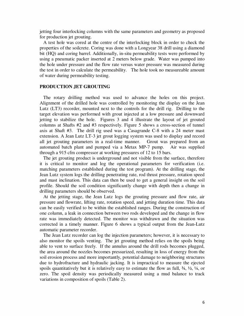
PRODUCTION JET GROUTING
The rotary drilling method was used to advance the holes on this project.
Alignment of the drilled hole was controlled by monitoring the display on the Jean
Lutz (LT3) recorder, mounted next to the controls for the drill rig. Drilling to the
target elevation was performed with grout injected at a low pressure and downward
jetting to stabilize the hole. Figures 3 and 4 illustrate the layout of jet grouted
columns at Shafts #2 and #3 respectively. Figure 5 shows a cross-section of tunnel
axis at Shaft #3. The drill rig used was a Casagrande C-8 with a 24 meter mast
extension. A Jean Lutz LT-3 jet grout logging system was used to display and record
all jet grouting parameters in a real-time manner. Grout was prepared from an
automated batch plant and pumped via a Metax MP-7 pump. Air was supplied
through a 915 cfm compressor at working pressures of 12 to 15 bars.
The jet grouting product is underground and not visible from the surface, therefore
it is critical to monitor and log the operational parameters for verification (i.e.
matching parameters established during the test program). At the drilling stage, the
Jean Lutz system logs the drilling penetrating rate, rod thrust pressure, rotation speed
and mast inclination. This data can then be used to get a general insight on the soil
profile. Should the soil condition significantly change with depth then a change in
drilling parameters should be observed.
At the jetting stage, the Jean Lutz logs the grouting pressure and flow rate, air
pressure and flowrate, lifting rate, rotation speed, and jetting duration time. This data
can be easily verified to be within the established ranges. During the construction of
one column, a leak in connection between two rods developed and the change in flow
rate was immediately detected. The monitor was withdrawn and the situation was
corrected in a timely manner. Figure 6 shows a typical output from the Jean-Lutz
automatic parameter recorder.
The Jean Lutz recorder can log the injection parameters; however, it is necessary to
also monitor the spoils venting. The jet grouting method relies on the spoils being
able to vent to surface freely. If the annulus around the drill rods becomes plugged,
the area around the nozzles becomes pressurized, resulting in loss of energy from the
soil erosion process and more importantly, potential damage to neighboring structures
due to hydrofracture and hydraulic jacking. It is impractical to measure the ejected
spoils quantitatively but it is relatively easy to estimate the flow as full, ¾, ½, ¼, or
zero. The spoil density was periodically measured using a mud balance to track
variations in composition of spoils (Table 2).

7
The spoils were sampled and cylinders cast for compressive strength testing. The
cylinders were filled with spoils typically in lifts and tamped to avoid air pockets and
stored in an area to avoid disturbance. This sampling method is an indication of the
material but may not be an accurate representative especially if mixing is poor. As
mentioned coring is typically intrusive and destructive so if strength is a key
parameter other means such as pressuremeter testing may be used.
Fig. 3. Layout of Jet-Grouted Columns at Shaft #2
Fig. 4. Layout of Jet-Grouted Columns at Shaft #3

8
Fig. 5. Cross-section Along Tunnel Axis at Shaft #3
Table 2. Spoil Densities Measured from the Ejected Spoil at the YDSS Project
Column I.D. Measured
spoil density
(g/cm3)
Comment Jet grouting date
YDSS Shaft #2,
Test #7
1.90 No adjacent columns were grouted April 12, 2007
YDSS Shaft #2,
Column A-3
1.97 Adjacent column B3 was grouted
24 hrs before
April 23, 2007
YDSS Shaft #2, Column A-1
1.92 Adjacent columns B1 was grouted 24 hrs ahead of time
April 24, 2007
YDSS Shaft #2,
Column L-5
1.90 /2.02 No adjacent columns were
grouted. Samples taken from the
top and bottom respectively from
the ejected spoil flow.
April 24, 2007
YDSS Shaft#2 A-2 1.88 Adjacent columns A1, A3 and B1
were grouted 24 hrs ahead of time
April 25, 2007
YDSS Shaft#2 C-2 1.94 Adjacent columns C1,C3,B1and
D2 were grouted 24 hrs ahead of
time
April 25, 2007
YDSS Shaft #2 F-1 1.87 Adjacent columns E1,E2 &G1
were grouted 24 hrs ahead of time
May 3, 2007
YDSS Shaft #3 I-1 1.92 No adjacent columns were grouted May 22,2007
YDSS #3, D7a 1.55 All adjacent columns grouted 24
hrs ahead of time
May 29,2007
YDSS Shaft #3 G3 1.92 Adjacent columns G4,
F3,H2,H3,H4 were grouted 24 hrs
ahead of time
May 29, 2007
Sterling Road P3 1.86 P1 and P2 were grouted 24 hrs ahead of time
Nov, 2010
Note: Injected grout S.G. =1.41 at YDSS and S.G.=1.57 at Sterling Road.

9
Fig. 6. Typical Jet-grouted Digital Log from Jean Lutz Monitor
The spoil densities stayed above 1.90 g/cm3 for most of the columns but dropped as
surrounding columns were installed.
At the start of production jet grouting a primary-secondary-tertiary-quaternary
(P,S,T,Q) sequence was followed, but very soon, it became apparent this was not
practical due to the working area being very tight making rig movement time
consuming. In order to improve productivity, a fresh column to fresh column based
sequence was implemented. Most of the new columns were jet grouted while the
adjacent columns were freshly installed (i.e. less than 24 hours curing time).

10
High production rates were achieved with the rod carousel and the 24-meter lattice
mast extension on the C-8 drill rig. This allowed for fast drill down times and for the
columns to be constructed in a single stroke without stopping for removal of rods
during column jetting operation.
The capabilities to store grout in a large 7 cubic meter agitator and to batch grout
quickly were important in allowing columns to be constructed without interruption.
At Shaft #2, a total of 75 columns were jetted in 14 working days, with an average
rate of 5.4 columns per day. At Shaft #3, a total of 149 columns were jetted in 20
working days, with an average production rate of 7.45 columns per 10 hour working
day.
QUALITY ASSURANCE/QUALITY CONTROL
The following components of the construction methodology assisted in maintaining
quality of the finished product:
• Careful planning of the general site arrangement, including allowing for
cement delivery, spoils containment and spoils storage/disposal.
• Pre-production test programs to establish the drilling and jetting parameters.
• Confirmation of verticality and ensuring a stable footprint for the drill rig.
Verticality was tracked and adjusted through the Jean Lutz monitoring
system.
• Control of the batching operation including measurement of specific gravity
of the grout and recording of each batch mixed.
• Used lattices to extend the drilling mast in order to ensure continuous jetting
operation.
• Incorporated large grout holding tank to supply sufficient grout during jetting.
• Computerized logging and display of jetting parameters for easy verification.
• Checked spoil and air returning during jetting and taking grout and spoil
samples periodically.
• Post-production test program to check the soilcrete strength, integrity and
permeability.
POST CONSTUCTION VERIFICATION PROGRAM
The post construction verification program included coring to check integrity,
unconfined compressive strength testing of spoils samples to confirm strength and in-
situ water pressure testing to check the permeability of the grouted zone (Table 3).
Core holes #1 and #2 were performed at the center of the interlocked columns in the
test zone and core holes #3, #4 and #5 were performed within the grouted production
zone. In-situ water test showed that the treated zone had a permeability of less than
10-5
cm/sec. Many of the boreholes took no measureable quantity of water over a 5
minute interval. Testing was conducted at an effective pressure of 1 psi per foot
depth. Table 3 shows the unconfined compressive strength testing results. Figure 7
shows the TBM during break-in at Shaft #3.

11
Fig. 7. TBM Break-in at Shaft #3
Table 3. UCS Test Results of Spoil Samples
Notes:
1. Samples were taken from the spoil around the columns during the time of
jetting.
2. Sample cylinder size dia.=76mm H=152mm.
3. Grout W/C=1.25 by weight. Type 20 cement used.
CONCLUSIONS
The following conclusions can be drawn from this case study:
• Jet grouting is an effective ground modification technique to stabilize problem
soils and provide containment of ground water.
Date of
sampling
Location of
sampling
Sample
Cylinder#1
Sample
Cylinder#2
Sample
Cylinder#3
S.G. from
spoil
Curing
time
(days)
UCS
(MPa)
Curing
time
(days)
UCS
(MPa)
Curing
time
(days)
UCS
(MPa)
24-Apr-
07 Shaft #2, Pile A-1 7 3.7 28 7.2 28 6.7 1.92
25-Apr-
07 Shaft #2, Pile A-4 7 2.7 28 5.9 28 6.4
26-Apr-
07 Shaft #2, Pile D-5 7 3.9 28 4.8 28 4.3 1.98
27-Apr-
07 Shaft #2, Pile J-4 7 2.3 28 4.5 28 5.7 1.96
28-Apr-
07 Shaft #2, Pile K-4 6 4.1 30 9.6 30 9.8 1.83

12
• The unconfined compressive strength (UCS) of the jet-grouted soil ranged
from 4.6 MPa to 9.7 MPa after 28 days compared to a specified minimum of
2MPa.
• The average in-situ permeability of the jet grouted column was less than 1 x
10-5
cm/sec
• A well-structured quality control/quality assessment program is vital for an
effective jet grouting project.
• The Jean Lutz LT3 data acquisition system provided invaluable information to
verify the injection parameters and evaluate the effectiveness of production
work on a real time basis.
• Column location and alignment are important aspects in the execution of a jet
grouting project.
• A field trial must be performed for each jet grouting project in order to
evaluate the effectiveness of the equipment and the selection of the
appropriate injection parameters.
• A specific jet grouting energy of 37.3 MJ/m created an average soilcrete
column of 1.5 m diameter within the limits of the subsurface conditions at the
YDSS Project.
REFERENCES
Earth Tech, (2005), “YDSS Interceptor Sewer – New Comparison of Alternative
Route Alignments”, Contract No. B8578, York Region, Ontario, Canada.
Xanthakos, P., Abramson, L. And Bruce, D., (1994), “Ground Control and
Improvement”, John Wiley & Sons, New York.