a castrogiovanni-acent-ices.pdf
TRANSCRIPT
A premier aerospace and defense company
A High Efficiency g yInertial CO2 Extraction System
(ICES)(ICES)
Dr. Anthony Castrogiovanni, Dr. Vladimir Balepin,Andrew Robertson, and Bon Calayag
Presented at the
NETL CO Capture Technology MeetingNETL CO2 Capture Technology MeetingPittsburgh, PAJuly 11, 2012
1

A premier aerospace and defense company
Company Backgrounds
• ATK is a leading aerospace & defense contractor• ACENT is a small business dedicated to applying expertise in aerospace and defense to clean energy challenges
• Founded in 2007, ACENT is developing
• ATK is a leading aerospace & defense contractor• ATK GASL in Ronkonkoma, NY operates the ATK Center for Energy and Aerospace Innovation
• Expertise and research interests include :• Aerospace propulsion Founded in 2007, ACENT is developing
technologies in CO2 capture, algal biomass, hydrogen vehicles, and enhanced oil recovery
• Aerospace propulsion• Carbon capture• Hydrogen fueled vehicles• Clean coal technologies• Oil recovery solutions• Oil recovery solutions
• ICES utilizes some methods developed under
2
a DOE SBIR with ACENT

A premier aerospace and defense company
Project Overview
Funding Summary:ARPA e: $ 2 693 KARPA-e: $ 2,693 KATK and ACENT Cost Share: $ 632 KNYSERDA (New York State) $ 200 K ( ) $TOTAL $ 3,525 K
Project Performance Dates:Phase 1: July 2010 – March 2011 (completed)Ph 2 J l 2011 J 2013 ( i )Phase 2: July 2011 – June 2013 (ongoing)
Project Participants:Project Participants:Alliant Techsystems (ATK)ACENT Laboratories LLC
3
WorleyParsons

A premier aerospace and defense company
Overall Project Objectives
• Demonstrate proof-of-concept of aero-thermodynamic CO condensation and separationCO2 condensation and separation
• Develop and benchmark analysis tools with experimental d t t bldata to enable:
• Scaling of demo system to power plant size
• Projection of economics in terms of COE and parasitic loads
• Provide basis for next-phase slip-stream testing with real flue gas
• Minimize flue gas pressurization requirements
• Maximize CO2 capture (>90% goal)
4
Maximize CO2 capture ( 90% goal)
A premier aerospace and defense company
ICES Technology Fundamentals
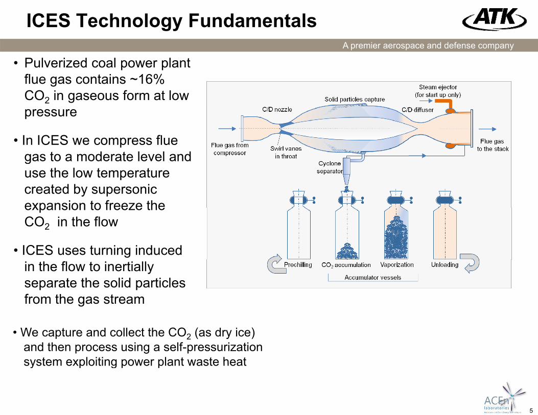
• Pulverized coal power plant flue gas contains ~16% CO2 in gaseous form at low pressure
• In ICES we compress flue gas to a moderate level andgas to a moderate level and use the low temperature created by supersonic expansion to freeze theexpansion to freeze the CO2 in the flow
• ICES uses turning induced in the flow to inertiallyseparate the solid particles from the gas stream
• We capture and collect the CO2 (as dry ice) and then process using a self-pressurization system exploiting power plant waste heat
5
system exploiting power plant waste heat

A premier aerospace and defense company
ICES on a P-T Diagram – Supersonic Expansion
12.01000
Isentropic Expansion of 16% CO2 in Nitrogen Relative to Phase Diagram of CO2
Liquid Phase
10.0100
Triple Point
Region of incipient
8.010
mbe
r
[psia]
pcondensation Gas Phase
4.0
6.0
0.1
1
Mach Num
Pressure [
Evolution of Partial Pressure of CO2 during Isentropic Expansion in Supersonic Nozzle(p0=30psia, T0=520ºR)
Solid Phase
2.00.01
(p0 30psia, T0 520 R)
0.00.001
0 100 200 300 400 500 600
T [R]
6
Temperature [R]

A premier aerospace and defense company
ICES Integration in PC Plant
18Flue Gas C l
Flue Gas Compressor
TBD Coolant
1719
22
Cooler Compressor
ICES Unit
21
22ICES Unit
Water20
21
7

A premier aerospace and defense company
ICES System Schematic
Compressor/HEX16
T 330K
18 19
22
HEX
Solid CO2
Capture DuctFluegas
Supersonic expansion
T=330KP=1.05 atm15% CO2
Subsonic diffusion
HEX
Cyclone separator (slip gas + CO2)
Flue gas from FGD T=300K
P=1.03 atm T=300KP=2.0 atm
T=400KP=1 atm<1.5% CO2
X
X
X X
T=298KP 150 t
21
CO accumulation
P=150 atm>99.5% CO2
CO2 accumulation & self pressurization system
8
X
Water Drain20
A premier aerospace and defense company
ICES Economic Impact
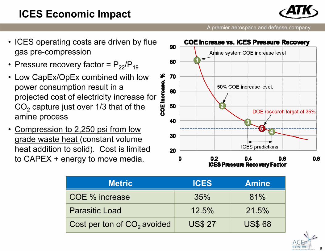
• ICES operating costs are driven by flue gas pre-compressionP f t P /P• Pressure recovery factor = P22/P19
• Low CapEx/OpEx combined with low power consumption result in a
j t d t f l t i it i fprojected cost of electricity increase for CO2 capture just over 1/3 that of the amine process
• Compression to 2,250 psi from low grade waste heat (constant volume heat addition to solid). Cost is limited t CAPEX + t dito CAPEX + energy to move media.
Metric ICES AmineCOE % increase 35% 81%Parasitic Load 12.5% 21.5%
9
Cost per ton of CO2 avoided US$ 27 US$ 68

A premier aerospace and defense company
Energy Consumption
Process Minimum Energy [kJ/kg CO2]
ICES[kJ/kg CO2]
Amine[kJ/kg CO2]
S ti 175 683*Separation -175 -683* -CO2 Compression -247 ~68** -Total -422 -751 -1,506Total 422 751 1,506
* Pre-compression of flue gas to 2 bar (absolute)** + Approximately 760 kJ/kg of low grade waste heat used to compress CO2from solid phase to 2 250psiafrom solid phase to 2,250psia
Fixed volume at ambient
~760 kJ/kg latent sensible heat
Supercritical CO2
pressure partially filled
with solid CO2 at 200 ºF
Initial Volume % filled with solid
Pressure at 70ºF [psia]
2
-200 ºF filled with solid 70 F [psia]
60% 3,00065% 6,000
10
Compression energy is nearly “economically free” but it is not “thermodynamically free” i.e. this energy would otherwise be wasted

A premier aerospace and defense company
ICES Plant Integration and Footprint
An ICES system sized for 545MW-equivalent flue gas contains twelve 60” ICES units (flue gas compression not shown)
L= 183 ftL= 183 ftW= 60 ftH = 70ft
ICES is projected to have a significantly smaller footprint and complexity compared to competing CO2 capture technologies and hence significantly
11
compared to competing CO2 capture technologies and hence significantly lower capital and maintenance costs

A premier aerospace and defense company
Key Advantages of ICES over other options
• No moving parts (after start)
N h i l / dditi th bl di• No chemicals/additives or other consumable media
• No refrigeration expense – low temperatures from supersonic expansionexpansion
• Inexpensive construction (concrete, sheet metal)
• Small footprint• Small footprint
• ICES units in test are equivalent to 0.3-0.6 MW slip stream
• The latest unit (0 3 MW) is 24” x 24” x 3”• The latest unit (0.3 MW) is 24 x 24 x 3
• Small size enables distributed deployment for other process applications in the petroleum and chemical industriespp p
• Availability of “cold sink” in solid CO2 accumulated
12

A premier aerospace and defense company
ICES Development Challenges
• Development of optimized supersonic contour to maximize particle size/migration and minimize pressuremaximize particle size/migration and minimize pressure losses
• Minimization of “slip gas” that is removed with solid CO2
• CO2 purity unknowns - other flue gas impurities thatCO2 purity unknowns - other flue gas impurities that condense will be removed with the CO2
S lid CO t/ lf i ti• Solid CO2 management/self pressurization
• This really is rocket science….but once the design is y gcomplete, it is easy and inexpensive to build and operate
13

A premier aerospace and defense company
Project Status – Phase 1
• Phase 1 and early Phase 2 efforts focused on an axisymmetric system with swirl
ICES test bench
14

A premier aerospace and defense company
Axisymmetric System Results
Phase 1 data showed good CO2 condensation and apparent, but erratic migration due to unsteady and separated flowerratic migration due to unsteady and separated flow
Outer (glass) wall)
CenterbodySolid CO2
15

A premier aerospace and defense company
We recently changed to a 2D version of ICES
• Better aerodynamic performance (lowerperformance (lower losses)
• Easier to fabricate d t t
Aluminum plenum chamber and throat
Aluminum plate reinforces plenum chamber
and test• No swirl vanes to
induce Clear acrylic sidewallsturbulence/wake
effects• Simpler capture duct
Clear acrylic sidewallsSupersonic flowpath
components made on 3D printer (ABS)
without swirlVacuum interface flange (steel)
16

A premier aerospace and defense company
Gen5 Test Article Design – ATK Installation
24” Vacuum Pipe
17

A premier aerospace and defense company
Test Data Comparison to CFD – Static Pressure
0.45
0.5
Test Data - Top SurfacesT t D t B tt S f
0.35
0.4
cham
ber)
Test Data -BottomSurfacesCFD Simulation - Top SurfacesCFD Simulation - Bottom SurfacesMach 1 9
0 25
0.3
tion
(Ps/
Pc Mach 1.9Mach 2.1Mach 2.75
0 15
0.2
0.25
ress
ure
Rat
0.1
0.15
Stat
ic P
r
Nucleation Begins
0
0.05
-5 0 5 10 15 20 25 30
18
X Position in Rig Coordinates

A premier aerospace and defense company
Laser Particle Imaging Diagnostic
Test Article
High Speed HD Laser Sheet Image cameraImage
19
Nd:YAG Laser

A premier aerospace and defense company
1, 10, and 100 Micron Particle Trajectories
1 μm1 μm
10 μm
100 μm100 μm
20
At 10 microns+ particles separate and coalesce allowing for a slender capture slot

A premier aerospace and defense company
Three modes in typical ICES test
CO2 migration toward lower wall evident
1) Air flow only
wall evident
2) 30 psi, 20% CO2
Optical and CO2 sampling results show condensation as e pected b t less than desired migration e ident Particle si e
3) 30 psi, 10% CO2
21
expected, but less than desired migration evident. Particle size does not appear large enough in these tests

A premier aerospace and defense company
Condensate Particle Size Control
• Classical nucleation theory provides basis for predicting critical condensate cluster size and subsequent growth rate:
• Both are strong function of the saturation ratio (S) = partial pressure of vapor/saturation pressure (pv/ps)
0 8
1
1.2
Diameter
• Maximum initial cluster size near S=1• Desirable to grow these clusters versus
0 2
0.4
0.6
0.8
s Critical Cluster D nucleating new ones at higher S
• Nozzle contour shape needs to be optimized for this purpose
‐0.4
‐0.2
0
0.2
Dim
ension
less • Need to further increase residence time
of flow in this critical region• Increasing scale toward power plant
i ill h l
22
0.900 0.950 1.000 1.050 1.100
Saturation Ratio
size will help

A premier aerospace and defense company
Current Plans
• Remaining portion of Phase 2
I ti t fl di ith lid CO ( lf t d) d th• Investigate flow seeding with solid CO2 (self generated) and other media to promote large particle formation (ongoing)
• Update contour to further optimize particle sizeUpdate contour to further optimize particle size
• Integration of capture duct to remove CO2
• Integration of diffuser to return flow to atmospheric pressure with• Integration of diffuser to return flow to atmospheric pressure with minimal losses
• “Phase 3”
• Ideal next step desired is a slip stream test, e.g. at the National Carbon Capture Center (NCCC)
23

A premier aerospace and defense company
Accomplishments to date
• Three ICES configurations have been developed and tested to datetested to date
• Demonstrated clean nozzle flow with low apparent losses (to be verified with later diffuser tests)
• Demonstrated supersonic condensation with someDemonstrated supersonic condensation with some migration
Pl i l t i ti l i t hi d i d• Plans in place to increase particle size to achieve desired migration performance
24

A premier aerospace and defense company
Acknowledgements
ARPA E:
Dr. Karma Sawyer, Dr. Scott Litzelman, Dr. Daniel Matuszak, Dr. Mark Hartneyy , , , y
NYSERDA:
Dr. Barry Liebowitzy
ATK & ACENT Labs:
Dr. Pat Sforza, Troy Custodio, Vincenzo Verrelli, Skip Day, Dean Feola, Ed Mihalik, Florin Girlea, Kirk Featherstone, Fred Gregory, Randy Voland
25

A premier aerospace and defense company
BACKUP
26

A premier aerospace and defense company
Schematic of Condensation Process
S = ps / pv , where pv is the partial pressure of the vapor and ps is the vapor saturation pressure at the temperature of the system.
27