a circuit board manufacturer's wastewater treatment …infohouse.p2ric.org/ref/27/26234.pdf ·...
TRANSCRIPT
A CIRCUIT BOARD MANUFACTURER'S WABTEWATER TREATMENT BYBTEM A BEMI-CLOSED LOOP CASE STUDY
By Robert F. Lee
Rogers Corporation Rogers, Connecticut
INTRODUCTION
Rogers Corporation is a multi-locational, international company, headquartered in Rogers, Connecticut. The company manufactures products ranging from foamed urethane materials used for shoes to sophisticated microwave circuitry used in military high performance aircraft. Oqe of the Arizona based divisions, that produces flexible circuits, faced a need to up- date existing wastewater treatment and to increase productive capacity. This presentation discusses the approach used to solve that situation.
BACKGROUND
With the passage of the Resource Conservation Recovery Act (RCRA) , Comprehensive Environmental Response, Compensation and Liability Act, and the amendments to the Clean Water Act that occurred between 1977 and 1981, Corporate management determined that, at this division, existing water and wastewater treatment facilities and existing procedures to dispose of metal containing sludges, via off-site land disposal, were inadequate to meet short and long term requirements and totally unable to handle future production needs. Additionally, a number of ancillary problems existed, such as: periodic variations in city supplied water pressure, frequeht variations in city supplied water quality and the ever present threat of water rationing.
In 1981, plating operations included: acid copper, tin/lead, tin, nickel, gold, electroless nickel and electroless copper; etching operations included: cupric chloride and alkaline etch. The plating area was equipped with a continuous flow-through pH neutralization and metals precipitation system, which whs rated at about 2 0 , 0 0 0 G P D . The etching area was equipped with its own pH neutralization and metals settling system which was rated at a maximum of 20,000 G P D flow. Both systems were at least 8-10 years old, experiencing frequent mechanical breakdowns and were at that time periodically having flows in excess of design capabilities. Also, during this period, the division was experiencing a rapid ramp-up of production levels as well as the introduction of numerous new processes.
1

PHABE I (Data Colleotion)
Meetings were held with division management, including engineering, marketing, production and sales to develop information on projected capacity needs over the next five year period. Following these meetings, a program of intense sampling and monitoring of flow rates, from various operations was established.
Concurrently, meetings were held with plant engineering to review status of current services, such as: electric capacity, water usage, water conditioning processes (softening and demineralization, plant layouts, piping layouts, maintenance records on wastewater treatment systems and a host of other operational service details. A sampling and flow monitoring program of incoming water was established and run parallel to the effluent sampling program.
Finally, as the effluent characterization data base began to grow, we began to review both existing regulations and anticipated likely directions of future ones. This review led to an early decision that at least two primary goals had to be achieved by any action taken: namely: (1) water discharges had to be reduced by reusing as much water as possible; and ( 2 ) metal containing sludge levels should be eliminated or reduced to the lowest practical amount.
This phase of work ran from February, 1981 to November, 1981 (9 months). There were some significant surprises that emerged: plant wide effluent discharges now averaged around 150,000 GPD, the etching wastetreatment system was running at 300% of rated capacity and climbing, 2,000 gallons of excess etchant (containing approximately one and one-half pounds of copper/gallon) were being removed for treatment per quarter, 4,000 gallons of metal containing sludge were being removed for landfilling every quarter, incoming water quality fluctuated between 1,200 PPM TDS and 3,000 PPM TDS (with an average calcium hardness of 600 PPM), incoming water pressure varied from 125 psi to as low as 15 psi, softeners functioned only about 60% of the time, demineralized water quality was highly variable and availability was not constant and finally, flows averaging about 20,000 GPD were occurring when no production existed. One significant positive surprise was that, with so much flow, we rarely exceeded metal limits, in effect at that time, on the effluent.
This data allowed us to make some realistic projections and gave us rational insights into why we were seeing some system performance fluctuations. The first projection was that at 150,000 GPD, and growing, we would soon face a very severe water availability crisis, being in a water scarce area to begin with. The second projection was that our levels of
2
sludge generation, which was going to landfill, would continue to increase not only in volume, but also in potential for future liabilities. Some of the insights showed that one of the major reasons for both softener and demineralizer performance variance was due to the fluctuation of incoming water quality and pressure.
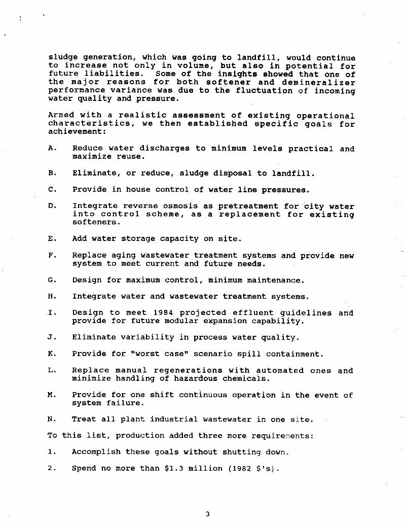
Armed with a realistic assessment of existing operational characteristics, we then established specific goals for achievement:
A.
B.
C .
D.
E.
F.
G .
H.
I.
J.
K.
L.
M.
N.
To
1.
2.
Reduce water discharges to minimum levels practical and maximize reuse.
Eliminate, or reduce, sludge disposal to landfill.
Provide in house control of water line pressures.
Integrate reverse osmosis as pretreatment for city water into control scheme, as a replacement for existing softeners.
Add water storage capacity on site.
Replace aging wastewater treatment systems and provide new system to meet current and future needs.
Design for maximum control, minimum maintenance.
Integrate water and wastewater treatment systems.
Design to meet 1984 projected effluent guidelines and provide for future modular expansion capability.
Eliminate variability in process water quality.
Provide for @@worst case" scenario spill containment.
Replace manual regenerations with automated ones and minimize handling of hazardous chemicals.
Provide for one shift continuous operation in the event of system failure.
Treat all plant industrial wastewater in one site.
this list, production added three more requirenents:
Accomplish these goals without shutting down.
Spend no more than $1.3 million (1982 $ I s ) .
3
3 . Allow for 3 new plating lines and double current etching capability (to be added in 1983/1984).
PHASE I1 (TECHNOLOGY ASSE88"T)
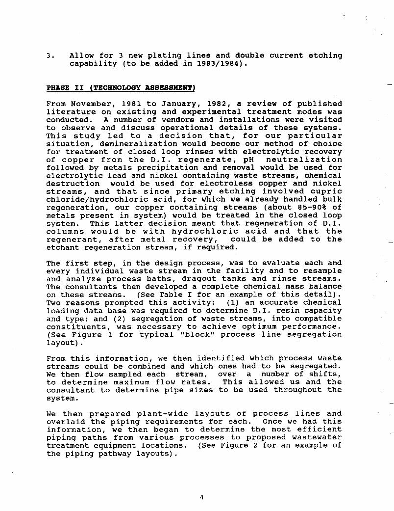
From November, 1981 to January, 1982, a review of published literature on existing and experimental treatment modes was conducted. A number of vendors and installations were visited to observe and discuss operational details of these systems. This study led to a decision that, for our particular situation, demineralization would become our method of choice for treatment of closed loop rinses with electrolytic recovery of copper from the D . I . regenerate, pH neutralization followed by metals precipitation and removal would be used for electrolytic lead and nickel containing waste streams, chemical destruction would be used for electroless copper and nickel streams, and that since primary etching involved cupric chloride/hydrochloric acid, for which we already handled bulk regeneration, our copper containing streams (about 85-90% of metals present in system) would be treated in the closed loop system. This latter decision meant that regeneration of D . I . columns would be with hydrochloric acid and that the regenerant, after metal recovery, could be added to the etchant regeneration stream, if required.
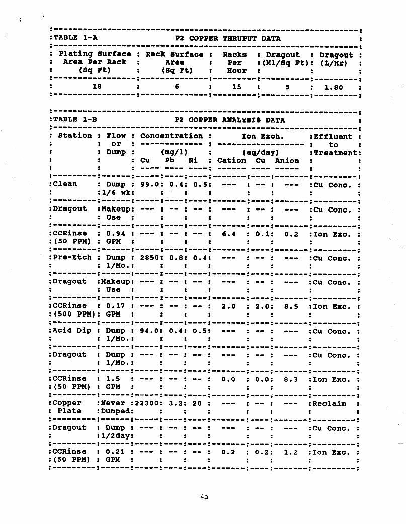
The first step, in the design process, was to evaluate each and every individual waste stream in the facility and to resample and analyze process baths, dragout tanks and rinse streams. The consultants then developed a complete chemical mass balance on these streams. (See Table I for an example of this detail). Two reasons prompted this activity: (1) an accurate chemical loading data base was required to determine D . I . resin capacity and type; and (2) segregation of waste streams, into compatible constituents, was necessary to achieve optimum performance. (See Figure 1 for typical I@blockl1 process line segregation layout).
From this information, we then identified which process waste streams could be combined and which ones had to be segregated. We then flow sampled each stream, over a number of shifts, to determine maximum flow rates. This allowed us and the consultant to determine pipe sizes to be used throughout the system.
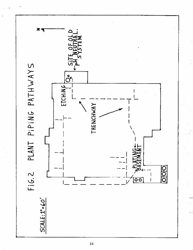
We then prepared plant-wide layouts of process lines and overlaid the piping requirements for each. Once we had this information, we then began to determine the most efficient piping paths from various processes to proposed wastewater treatment equipment locations. (See Figure 2 for an example of the piping pathway layouts).
4
4a

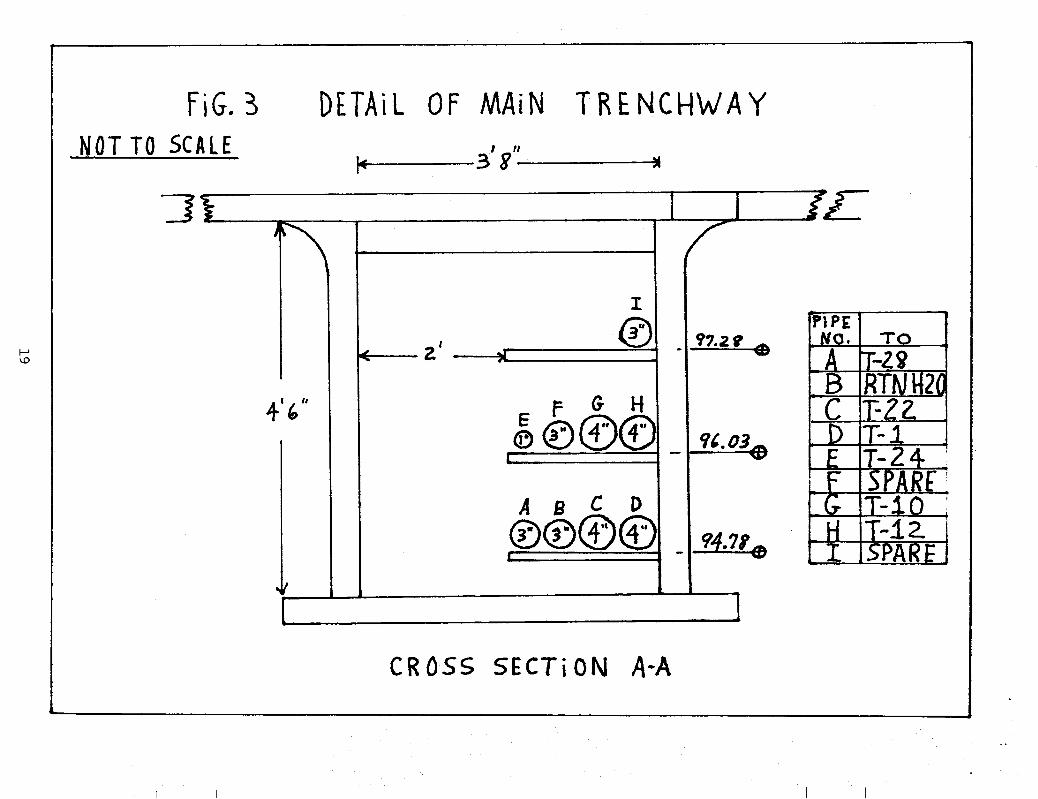
Since it was our goal to simplify operation, minimize maintenance and maximize control , we decided that where feasible we would gravity feed waste streams to treatment (this eliminated a large number of pumping stations) and pump treated water to process lines. To accomplish this and to provide maximum flexibility for future changes, a below grade trench network was designed, in house, to accommodate these pipes. This trench went from the existing plating room basement area, where it was decided that the holding tanks for wastewaters and pH neutralization/metals precipitation equipment would be located, to the various process line sites within the plant. (See Figure 3 for a detail of the main trenchway).
During the period from August to November 1982, the design work on the trenchway and segregation of flows was accomplished. At the end of this period, we had determined the nature and size of all required major equipment needs; solicitations for bids were sent out in November, 1982. In January, 1983 major equipment purchase costs and delivery schedules were complete and approval for capital was sought. At this time, estimates for project were approximately $1,150,000; this was within original target range. Approval for expenditure was received in February, 1983. Orders were placed according to predetermined schedules to insure timely receipt of equipment when required for installation.
PHASE IV (INSTALLATION)
The installation of the trenchway complex was completed in March, 1983. To accommodate productionts requirement for no shutdown, this work was done on third shift and weekends; this phase of construction took 6 weeks. This work was chosen to be done first because of our need to clear out existing equipment in the plating basement and our decision to pump existing effluent flows from this side of the plant over to the etching area side of the plant for treatment during the rest of the construction phase. Temporary treatment equipment was added to the existing etchant system wastewater treatment system to accommodate this added flow. To make the plumber's job a little easier, it was decided that all temporary piping would be white PVC and all ttfinaltt system pipes would be gray PVC piping; this decision saved us countless headaches during the course of construction.
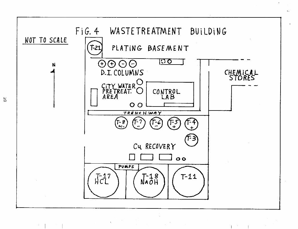
Next specifications and designs for a building addition, to house D . I . columns, water pretreatment, electrolytic recovery and a laboratory were completed in house. Construction commenced in August, 1983 and the building was essentially completed in November, 1983. (See Figure 4 for details of this building and layout of equipment).
5

Actual installation of treatment system equipment began in late November, 1983. Installation work was essentially completed in June, 1984 and start-up and debug of the system began in mid- June of 1984.
PHASE V (START-UP C DEBUO)
Water Pretreatment Modulo (Module I)
The first system module brought on stream was water pretreatment. City water is fed to a small, 5 0 0 gallon tank where it is adjusted for pH and a scale conditioner is added. From here the water overflows to another 5 0 0 gallon tank equipped with a level control, which controls water feed to the first tank, and an agitator. Water is then pumped through a sand filter and carbon filter, in series. (This accomplishes several things: (1) we now control system water pressure internally, ( 2 ) we remove any precipitated scale/sediment; and ( 3 ) we remove any residual chlorine from city water). All major pump installations are composed of two pumps; one on stream and the other on standby. Each pump is equipped with an amp-hour meter to record running time, used to schedule maintenance and operation is set so that when the next demand occurs the standby pump is activated; this provides alternating of pump use and insures pumps do not sit idle for long periods of time.
From here water is fed to a Reverse Osmosis Unit which removes about 7 5 % of the contained total dissolved solids. Product water is then fed to two sets of anion/cation columns for deionization. The reject brine is fed to sewer discharge. The R . O . unit replaces the old water softeners allowing for continuous use, as opposed to the prior practice of having to manually regenerate the softeners: this accomplished our goal of reducing labor where possible.
The two sets of D . I . (anion/cation) columns are recycled units; that is they are the manually regenerated ones we had, on the old water pretreatment system, that we modified by automating regeneration. The dual system allows for one set of columns to be on stream, while the other set is either being regenerated or on standby.
From the D . I . columns, the water is fed to a 25,000 gallon storage tank. This tank is equipped with level controls/alarms. Tank is located at ground level and normally feeds, by gravity, to holding tanks in the plating basement. However, dual pumps were provided to feed water directly to process, during start-up, and remain to perform the same function should the main system go down. Additionally,
6
these pumps provide continuous recirculation of water within the tanks to control algae build-up. Finally, these pumps are used to feed water to D . I . columns and carbon bed for regeneration/backflushing needs. See Figure 5 , Module One Schematic of Pretreatment Cycle.
closed Loop D.I. Water Module (Modula 11)
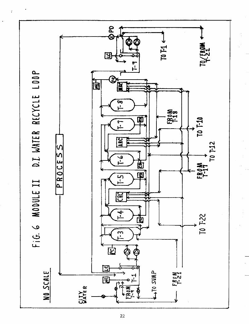
The second system module brought into operation was the semi- closed loop water treatment, which provides ongoing treated water for processes. See Figure 6 , Module Two for Schematic of this equipment.
In normal operation, all rinse waters not containing either lead or nickel metal, are returned, by gravity, to Tank #1 (T- 1). T-i is located in the plating basement and is equipped with a pH controller to adjust pH. Level controls activate dual station pumps which send this contaminated water up to the treatment building. T-1 is also fitted with an automatic valve (three-way) which can direct untreated city water or D . I . water, from the above ground storage tanks, as determined by system operator, to it. As an emergency feature, T-1 has a manually operated drain valve which will allow drainage of contents to a floor sump (part of the Spill Containment System) where water can be pumped to an emergency hold tank; from this tank, it can be pumped to neutralization/filtration and then to sewer.
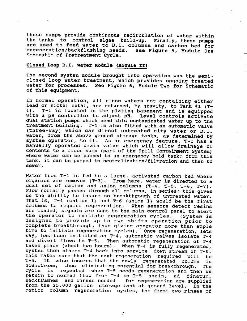
Water from T-1 is fed to a large, activated carbon bed where organics are removed (T-3). From here, water is directed to a dual set of cation and anion columns (T-4, T-5, T-6, T-7). Flow normally passes through all columns, in series; this gives us the ability to insure no breakthrough of untreated water. That is, T-4 (cation I) and T-6 (anion I) would be the first columns to require regeneration. When sensors detect resins are loaded, signals are sent to the main control panel to alert the operator to initiate regeneration cycles. (System is designed to provide up to two shifts operation prior to complete breakthrough, thus giving operator more than ample time to initiate regeneration cycles). Once regeneration, lets say, has been initiated on T-4, automatic valves isolate T-4 and divert flows to T-5. Then automatic regeneration of T-4 takes place (about two hours). When T-4 is fully regenerated, system then places T-4 back into service, down stream of T-5. This makes sure that the next regeneration required will be T-5. It also insures that the newly regenerated column is downstream, thus eliminating potential for breakthrough. The cycle is repeated when T-5 needs regeneration and then we return to normal flow from T-4 to T-5 again, ad finatum. Backflushes and rinses needed for regeneration are supplied from the 25,000 gallon storage tank at ground level. In the cation column regeneration cycles, the first two rinses of
7
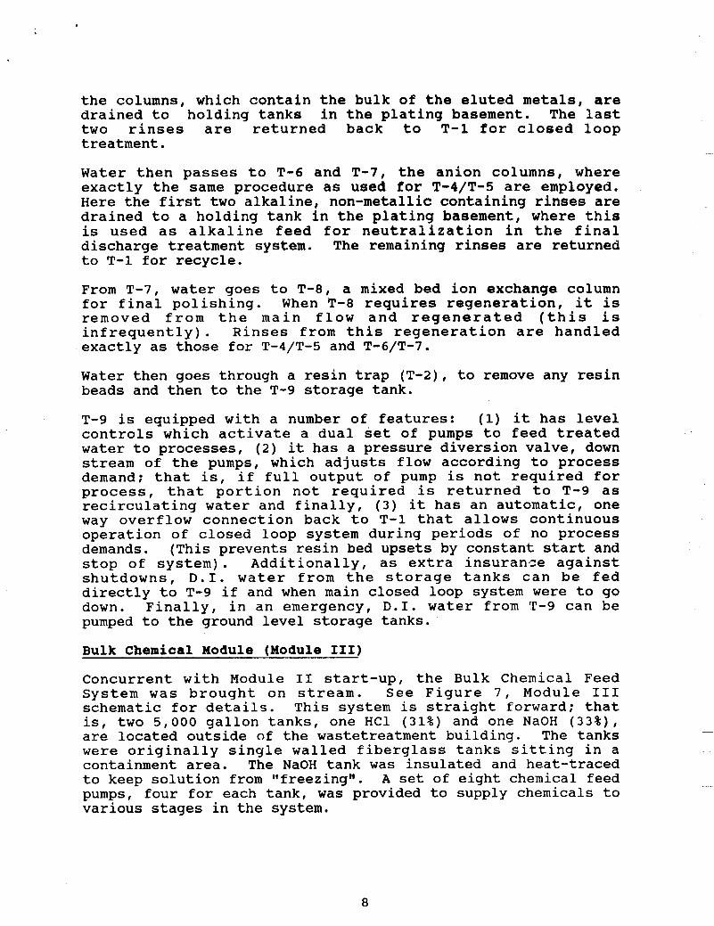
the columns, which contain the bulk of the eluted metals, are drained to holding tanks in the plating basement. The last two rinses are returned back to T-1 for closed loop treatment.
Water then passes to T-6 and T-7, the anion columns, where exactly the same procedure as used for T-4/T-5 are employed. Here the first two alkaline, non-metallic containing rinses are drained to a holding tank in the plating basement, where this is used as alkaline feed for neutralization in the final discharge treatment system. The remaining rinses are returned to T-1 for recycle.
From T-7, water goes to T-8, a mixed bed ion exchange column for final polishing. When T-8 requires regeneration, it is removed from the main flow and regenerated (this is infrequently). Rinses from this regeneration are handled exactly as those for T-4/T-5 and T-6/T-7.
Water then goes through a resin trap (T-2), to remove any resin beads and then to the T-9 storage tank.
T-9 is equipped with a number of features: (1) it has level controls which activate a dual set of pumps to feed treated water to processes, (2) it has a pressure diversion valve, down stream of the pumps, which adjusts flow according to process demand; that is, if full output of pump is not required for process, that portion not required is returned to T-9 as recirculating water and finally, ( 3 ) it has an automatic, one way overflow connection back to T-1 that allows continuous operation of closed loop system during periods of no process demands. (This prevents resin bed upsets by constant start and stop of system). Additionally, as extra insurance against shutdowns, D . I . water from the storage tanks can be fed directly to T-9 if and when main closed loop system were to go down. Finally, in an emergency, D . I . water from 't'-9 can be pumped to the ground level storage tanks.
Bulk Chemical Module (Module 111)
Concurrent with Module I1 start-up, the Bulk Chemical Feed System was brought on stream. See Figure 7 , Module I11 schematic for details. This system is straight forward: that is, two 5,000 gallon tanks, one HC1 (31%) and one NaOH ( 3 3 % ) , are located outside of the wastetreatment building. The tanks were originally single walled fiberglass tanks sitting in a containment area. The NaOH tank was insulated and heat-traced to keep solution from Igfreezinglg. A set of eight chemical feed pumps, four for each tank, was provided to supply chemicals to various stages in the system.
8
Effluent Neutralisation Modulo (Module IV)
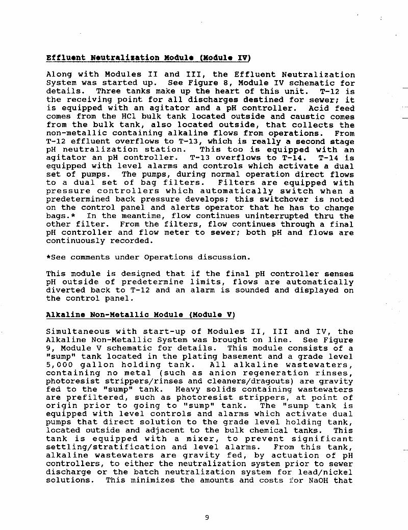
Along with Modules I1 and 111, the Effluent Neutralization System was started up. See Figure 8 , Module IV schematic for details. Three tanks make up the heart of this unit. T-12 is the receiving point for all discharges destined for sewer; it is equipped with an agitator and a pH controller. Acid feed comes from the HC1 bulk tank located outside and caustic comes from the bulk tank, also located outside, that collects the non-metallic containing alkaline flows from operations. From T-12 effluent overflows to T-13, which is really a second stage pH neutralization station. This too is equipped with an agitator an pH controller. T-13 overflows to T-14. T-14 is equipped with level alarms and controls which activate a dual set of pumps. The pumps, during normal operation direct flows to a dual set of bag filters. Filters are equipped with pressure controllers which automatically switch when a predetermined back pressure develops; this switchover is noted on the control panel and alerts operator that he has to change bags.* In the meantime, flow continues uninterrupted thru the other filter. From the filters, flow continues through a final pH controller and flow meter to sewer; both pH and flows are continuously recorded.
*See comments under Operations discussion.
This module is designed that if the final pH controller senses pH outside of predetermine limits, flows are automatically diverted back to T-12 and an alarm is sounded and displayed on the control panel.
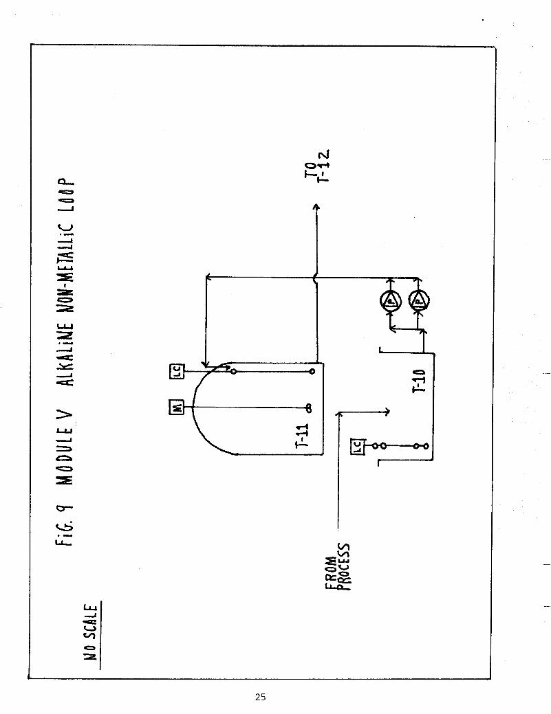
Alkaline Non-Metallic Module (Module V)
Simultaneous with start-up of Modules 11, I11 and IV, the Alkaline Non-Metallic System was brought on line. See Figure 9, Module V schematic for details. This module consists of a rrsumprr tank located in the plating basement and a grade level 5,000 gallon holding tank. All alkaline wastewaters, containing no metal (such as anion regeneration rinses, photoresist strippers/rinses and cleaners/dragouts) are gravity fed to the Irsumprt tank. Heavy solids containing wastewaters are prefiltered, such as photoresist strippers, at point of origin prior to going to rrsumprr tank. The Itsump tank is equipped with level controls and alarms which activate dual pumps that direct solution to the grade level holding tank, located outside and adjacent to the bulk chemical tanks. This tank is equipped with a mixer, to prevent significant settling/stratification and level alarms. From this tank, alkaline wastewaters are gravity fed, by actuation of pH controllers, to either the neutralization system prior to sewer discharge or the batch neutralization system for lead/nickel solutions. This minimizes the amounts and costs for NaOH that
9
would have to be used otherwise. (Virgin NaOH can be used, as well, if no alkaline wastewater is available or if more concentrated alkali is needed).
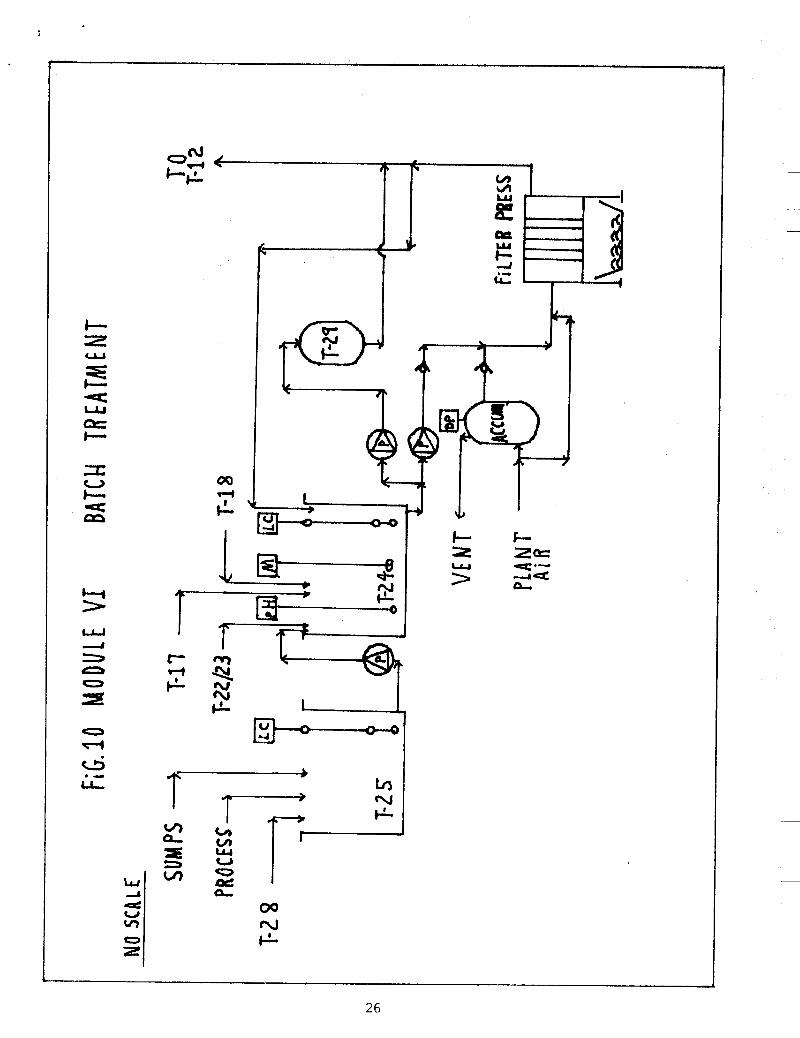
Lead/Nioksl Batoh Treatment Modulo (Modula VI)
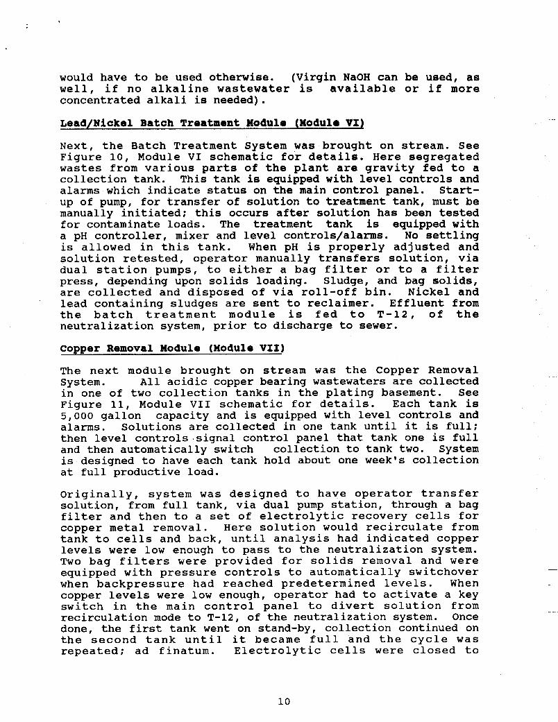
Next, the Batch Treatment System was brought on stream. See Figure 10, Module VI schematic for details. Here segregated wastes from various parts of the plant are gravity fed to a collection tank. This tank is equipped with level controls and alarms which indicate status on the main control panel. Start- up of pump, for transfer of solution to treatment tank, must be manually initiated; this occurs after solution has been tested for contaminate loads. The treatment tank is equipped with a pH controller, mixer and level controls/alarms. No settling is allowed in this tank. When pH is properly adjusted and solution retested, operator manually transfers solution, via dual station pumps, to either a bag filter or to a filter press, depending upon solids loading. Sludge, and bag solids, are collected and disposed of via roll-off bin. Nickel and lead containing sludges are sent to reclaimer. Effluent from the batch treatment module is fed to T-12, of the neutralization system, prior to discharge to sewer.
Copper Removal Module (Module VI11
The next module brought on stream was the Copper Removal System. All acidic copper bearing wastewaters are collected in one of two collection tanks in the plating basement. See Figure 11, Module VI1 schematic for details. Each tank is 5,000 gallon capacity and is equipped with level controls and alarms. Solutions are collected in one tank until it is full; then level controls.signa1 control panel that tank one is full and then automatically switch collection to tank two. System is designed to have each tank hold about one week's collection at full productive load.
Originally, system was designed to have operator transfer solution, from full tank, via dual pump station, through a bag filter and then to a set of electrolytic recovery cells for copper metal removal. Here solution would recirculate from tank to cells and back, until analysis had indicated copper levels were low enough to pass to the neutralization system. Two bag filters were provided for solids removal and were equipped with pressure controls to automatically switchover when backpressure had reached predetermined levels. When copper levels were low enough, operator had to activate a key switch in the main control panel to divert solution from recirculation mode to T-12, of the neutralization system. Once done, the first tank went on stand-by, collection continued on the second tank until it became full and the cycle was repeated; ad finatum. Electrolytic cells were closed to
10

atmosphere, which meant that gaseous build-up (chlorine gas) collected in the top of the two collection tanks; to compensate for this, these tanks were vented to the main exhaust duct, from plating and sent to the scrubber for removal. Scrubber spray water was recirculated, for a preset number of cycles and then discharged to T-12 of the neutralization system. (See operational discussion for changes made after start-up).
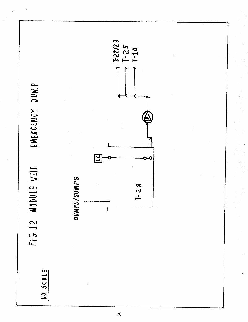
Emergenay Dump Module (Module VIII)
Tanks containing heavy concentrations of metal, such as pre- etch cleaners and plating tank dragouts, which require infrequent dumps, are connected to the emergency hold tank in the plating basement. This tank is equipped with level alarms and controls which signal the operator, via the main control panel, when solution is collected in tank. All dumps require manual initiation; usually, after notifying operator that the dump will be made. The emergency hold tank has a capacity of 3,000 gallons: no single dump tank, in the system, is larger than 600 gallons, so ample holding capacity is provided. If required, the operator can sample the collected wastes and make a determination of the best treatment mode. Tank has automatic valves, controlled from the main control panel, which can direct, via a single station pump to one of three destinations: (1) T-22/T-23 (Copper Removal Holding Tanks), ( 2 ) T-24 (Batch Treatment Module) or (3) T-10 (Alkaline Non- Metallic Sump Tank). (See Figure 12, Emergency Dump Module (Module VIII) Schematic for details).
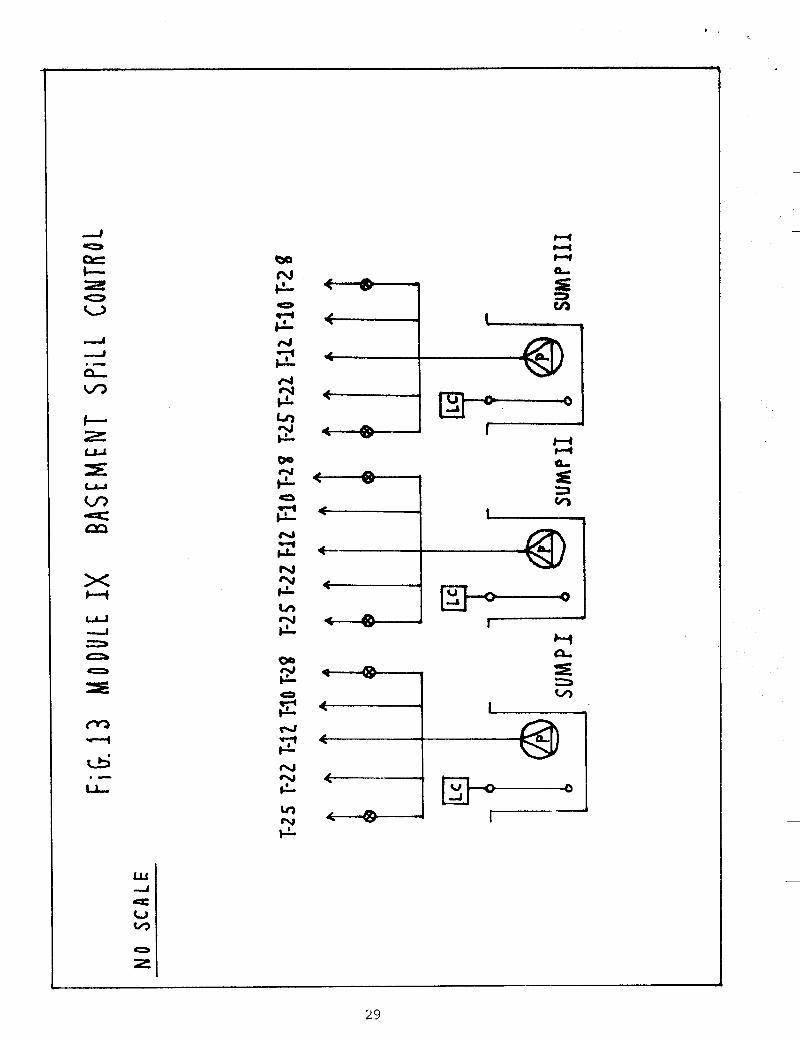
Spill Control Module (Module IX)
Spill control is an integral part of the total water/wastewater system. As mentioned earlier a trenchway was constructed to each process area in the plant: each process area is constructed such that any significant spill flows to the trench. In the etching area, because of the heavier flow potential for spills, a trench IIsump1I, behind a dam, is equipped with level controls which activate a single submersible pump that directs these to the emergency hold tank. The trenchway is lined and sloped so that any leakage, from pipes or dams, gravity flows down to the plating basement; here it flows onto the floor! which is also pitched to direct flows to collection trenches and sumps. Three separate trenchjsump systems are provided in the basement to collect spills/leaks. The floor and trench/sump systems are lined with chemical resistant coatings and the sumps are further protected by half-inch thick polypropylene linings. Each basement sump is equipped with level alarms and controls which notify the operator, via the main control panel, if a flooding condition is developing. Each sump also has three automatic valves which can direct, from the control panel, flows to: (1) T-22/T-23 (Copper Removal
11
Module Tanks), (2) T-12 (Neutralization System Prior To Sewer Discharge) and (3) T-10 (Alkaline Non-Metallic Sump). Additionally, each sump is equipped with two manually operated valves which can divert flows to: ( 4 ) T-25 (Batch Treatment Module Holding Tank) or T-1 (Process Water Holding Tank On closed Loop Module). Finally, a diaphragm pump, with 1,500 GPM flow capability, is located in the basement and can be activated, by the operator in the event of a city water main, or D.I. water storage tank, rupture and pump water direct to sewer. (See Figure 13, Module IX Schematic for details).
Control Panel
The control panel is located in the wastetreatment building laboratory. This control station consists of three panels: the first houses the motor controls and switches for the pumps, conductivity panel readouts, pH readouts and main on/off switches; the second contains fuse blocks, more pH/conductance readouts and pump switches; and the third, larger panel, contains all regeneration controllers, pressure controllers, relays, all flow rate panel readouts and a large status display board. This status board gives the operator a real time overview of all system functions and instant notice of abnormal performance of any critical operation. This board has light indicators which show normal operation (Green), standby or transient status (going to/from normal limits and to/from abnormal limits) (Yellow) and abnormal operation (Red). Additionally, an event recorder in this panel records every signal fed to the status board: the date, time, signal identification code and status for some 132 control points (black ink for normal, red ink for abnormal).
Like most wastewater treatment operators, ours performs routine analyses of effluent and runs batch treatment, as required. However, unlike most operators, ours is also in total control of all process operations. That is, since we treat not only waste water, but also process water, the operator can (if the situation warrants) isolate any process line from the system. Examples: (1) if a process line is experiencing problems and is discharging effluent outside of design parameters, the operator can divert those discharges to the emergency hold tank for short durations; (2) if the process line is, for whatever reason, discharging effluent beyond the system capability to handle, the operator can, terminate the flow of water to the process line (usually this is done after notifying supervisors) after suitable time allowed to clear the lines. Thus the operator of this Wastewater Treatment System is in reality the ttCzar" of operations.
The plant is equipped with emergency back-up electric power: however, should a major power failure occur, all automatic valves in the system are air operated (normally closed) and
12
will shutdown, terminating all flows. All solenoids in the system are also air operated; this coupled with air operated valves, provides a gradual, rather than instantaneous, system shutdown in the advent of a power failure. It also means a gradual startup, when power is returned; thus minimizing llhammeringll of pipes and reducing risk of damage.
START-UP BUMMARY
Combining Figures 5 through 13, we develop the total system configuration. See Figure 14, Total System Schematic for details. Although the total system appears quite complex, by breaking it down into individual modules, we were able to keep focused on specific operations.
A s with any Human endeavor, the best laid plans are still subject to Murphy's Laws; we were no exception. The overall project was completed within allowed time schedule, but was over-budget by some $250,000. Several factors contributed to this cost overrun: (1) an underestimation of plumbing labor (accounted for about $125,000), (2) unanticipated additional expenses to correct corrosion damage to existing basement structure, ( 3 ) unplanned changes in plating room layout, and (4) incorporation, into project, of a host of small llproduction j obsll.
The most serious problems involved: (a) just prior to last shipment of specified pumps, supplier went out of business; (b) after about three weeks operation, D.I. column rubber linings began to tlde-bondtt from base metal. In dealing with column supplier, we had to work around his filing for Chapter 11 and subsequent LBO.
Finally, during the course of this project, we underwent two extensive divisional management changes; this in turn led to some changes in lower level management. These changes required significant llreeducationtl of these individuals as to project I s objectives. The original project plan called for the designated system operator to join the project team at the start of the installation phase; however, due to these upper level changes in management, this did not occur until one week before actual startup. A s it was, although there were some hectic moments, the designated operator quickly absorbed the intricacies of the system and we became fully operational in September of 1984. The success of this project is due in large measure to four primary reasons: (1) a well laid out plan/schedule, (2) an extremely talented design team, ( 3 ) an excellent construction/installation crew, and (4) a highly dedicated and motivated treatment system operator.
13
OPERATIONS
During the course of the design and installation of this project, a series of procedural/equipment changes occurred:
1. Following several months of testing/development on electrolytic recovery of copper (Copper Recovery Module), a major event took place. That was the start-up of Inspiration Copper's Copper Waste Recovery Unit in Arizona. Prior to this, we had to ship copper bearing wastes to Southern California for recovery; an expensive and risky undertaking. The original intent of our own electrolytic recovery cells was to minimize this expense and risk. However, with Inspiration's start-up, we could inexpensively ship these wastes to their plant with minimal risk, since they are located just a couple of hours away. This development, coupled with increased demands on limited technical resources, led to a management decision to halt further work on our in house electrolytic recovery activity. Consequently, at present we can do one of two things with this copper bearing wastewater (depending on Inspiration's needs) ( a ) pump direct to tank truck, or (b) process wastewater through batch neutralization system to produce a cake for haul off in a roll-off bin. Depending upon copper market, our disposal costs are nothing or we produce a small income; this is a far cry from the approximate $3,000 - $4 ,000 per quarter we were paying for haulage to California.
Electrolytic recovery equipment was "moth-balledt1 and thus is available, for continued development, should conditions dictate that we must produce elemental copper ourselves.
2. Shortly after system start-up, problems with premature loading of the final effluent filters was experienced. These problems were traced to the photoresist stripping operations. By providing "point of origintt filtration, problem was alleviated and the need for the final effluent filters was removed. Units remain, if required for future needs, but are off-line.
3 . About one year after start-up of system, management decided to increase the capacity of the Electroless Plating Waste Treatment System and replace the small, original batch system with a larger proprietary unit. This reduced overall labor by allowing less frequent treatment cycles. This waste stream includes both dragout tanks and concentrated bath dumps.
4 . In 1988, a leak developed in the Bulk HC1 Storage Tank in the bottom tank flange and leaked about 2,000 gallons of acid into the containment pad around the tank.
14

Fortunately, the original containment structure prevented any release to the environment of HC1. However, as a result of this incident, these tanks were replaced with new, double walled tanks, the containment area was improved and an enclosure was installed around the tanks.
The system has been operating since mid-1984 and has performed to specification. Flows to sewer have been reduced to and stabilized at around 35,000 - 40,000 GPD; the semi-closed loop water recycle system runs at about 120 GPM (150,000 GPD), water line pressure variation no longer exists, water rationing threat no longer is a factor, water quality variances have been reduced to a level of insignificance, effluent to sewer meets current effluent guidelines, water and sewer bills have been reduced by 8 0 % (from 1982 levels, prorated for 1988 dollars), chemical consumption has been reduced and operator daily exposure to handling hazards of chemicals has been tremendously reduced, as compared to previous operations.
R.O. membranes have exhibited a three to four year life, within expectations, and D.I. resins have exceeded life expectancy of three years. Since start-up, production has increased both etching and plating capacity above original projections and with the changes noted above, the system has performed admirably.
As to future demands, the existing semi-closed loop system can go to 130 GPM (187,000 GPD) , existing water treatment and storage system can handle about 5 0 , 0 0 0 GPD make-up water. The neutralization system (to sewer) is close to capacity, but allowance has been made to install a duplicate system if required. Additional space allowance is provided for more D.I. columns, if required, for the semi-closed loop system.
ACKNOWLEDGEMENTS
The author wishes to express recognition and thanks to the following individuals and organizations that contributed to the success of the project: Mr. Charles Bergheimer (Ret.), Mr. Waymon Brooks (Ret.), Mr. Gerry Langelier, Mr. William Whiteley, Mr. Wayne Bixler, Mr. Vince Poleo and Mr. Me1 Harms of the Rogers Corporation; Mr. Frank Keery and Mr. Dan Casiraro, formerly with Rogers Corporation; Mr. Jim North and the Resource Consultant's organization; Mr. Rudy Mathis and the International Systems organization; Mr. Wallace Myers and the Americhem Engineering organization; K.J. Plumbing Contractors; and a host of other individuals and organizations, too numerous to mention.
15

Finally, the author wishes to express thanks to the following individuals who assisted in reviewing and typing this article: Mr. William Whiteley, Mr. Wayne Bixler and Ma. Debra Chatelle, all of the Rogers Corporation.
16

~ CLEAN DRAG ACID DIP
CC R DRAf OU
F i G. 1
PRE - ETC H
I
DRAG OUT
CU PLATiNG L i N E
CC R
T l-r
CC R ‘OPPER PLATE DRAG OUT
7
CC R
cu ONC. T (i Nk
I I I I I
2 -- .I--- >-
I I -i-
1 I 1 \ \
1 d- I J L I --I
I
18
P W
FIG. 3 NOTTO S C A L E
DETAiL OF MAiN TRENCHWAY
4'6''
JI r-
c 2
I
97.29
94. u3 4
94.783
1
CROSS SECTiON A-A
h: 0
NOT TO S C A L € F i G. 4 WA ST E T R E ATM € NT 8 U i LO i FJ G a PLATiNG BASEMENT
D.I. COLUEI\NS n
U 00- I L ~~
T R E N C H w s y I
..

LLI & a,
P I- .-
H Lu I -5 n 0 r:
In
E
I- < 3
LLI
w I 4 U u,
2 0
T
1
22

L
0
23

> U
.- u,
Y
lTT= U L c
00-
0
24
25
26

T- t/) e
s z n
UJ -J
V c/)
L 0
0
27
9,
3 5 n
u) Q
w d 4 U tn
I c-l cl( t4 a
3 s
s QI
3 w €
"1
29

w --I 4: u v,
f rah c
4 o c
30