a closer look at prevailing civil engineering practice
TRANSCRIPT

7/30/2019 A Closer Look at Prevailing Civil Engineering Practice
http://slidepdf.com/reader/full/a-closer-look-at-prevailing-civil-engineering-practice 1/83
A Closer Look at Prevailing Civil
Engineering Practice – What, Whyand How?
Vincent T. H. CHU ( 朱敦瀚朱敦瀚朱敦瀚朱敦瀚 )

7/30/2019 A Closer Look at Prevailing Civil Engineering Practice
http://slidepdf.com/reader/full/a-closer-look-at-prevailing-civil-engineering-practice 2/83
A Closer Look at Prevailing Civil Engineering Practice, What, Why and How? Vincent T. H. CHU
2
CONTENTS
Preface 3
1. Bridge Works 4
2. Concrete Structure 14
3. Drainage Works 24
4. Marine Works 30
5. Piles and Foundation 34
6. Roadworks 42
7. Slopes and Excavation 53
8. Tunneling 59
9. Site Investigation 66
10. Sewage and Waterworks 70
About the author 76

7/30/2019 A Closer Look at Prevailing Civil Engineering Practice
http://slidepdf.com/reader/full/a-closer-look-at-prevailing-civil-engineering-practice 3/83
A Closer Look at Prevailing Civil Engineering Practice, What, Why and How? Vincent T. H. CHU
3
Preface
It is indeed more than happy to realize that my previous engineering publications
have spread to Asia (Hong Kong, Singapore, Japan, Turkey, Philippines,
Mongolia, Vietnam, Pakistan, Malaysia), Europe (United Kingdom, Switzerland,
Spain, Germany, Bulgaria, Slovakia, Gospodarska Zbornica Slovenije), North
America (The United States and Canada), Australia, Barbados and South Africa. I
hope that through my writing work I could continue to share my engineering
knowledge with the rest of the world in an attempt to achieve simultaneous
progress in civil engineering.
It really took countless sleepless nights to complete this book. However, I really
enjoyed this writing process because it helped clear up some vague and forgotten
engineering knowledge and build up some brand new ones. I intend to write this
book in an easy-reading style as in my previous collections so that every readershould be able to pick up some gifts and useful knowledge from it.
Should you have any comments on the book, please feel free to send to my email
askvincentchu @yahoo.com.hk and discuss.
Vincent T. H. CHU
January 2010

7/30/2019 A Closer Look at Prevailing Civil Engineering Practice
http://slidepdf.com/reader/full/a-closer-look-at-prevailing-civil-engineering-practice 4/83
A Closer Look at Prevailing Civil Engineering Practice, What, Why and How? Vincent T. H. CHU
4
Chapter 1. Bridge Works
1. What is the purpose of leveling pad in bridge bearing?
Bridge bearings should be installed to lie horizontally on bridge piers andcolumns so that it would not induce eccentricity forces on substructure.However, the bridge superstructure requires different longitudinal andtransverse level and gradient in order to keep in line with the geometry ofthe road. As such, it is natural to follow that the superstructure can hardlymeet with substructure horizontally so that a leveling pad is introduced atthe bottom of the superstructure to join with bridge bearing. Wedge-shapedleveling pad is commonly used for better concrete mobility at the bridgebearings.
2. Central prestressing is normally required during construction inincremental launching method. Why?
The erection condition plays an important role to the structural design ofbridges when incremental launching method is adopted.
Each section of superstructure is manufactured directly against thepreceding one and after concrete hardens, the whole structure is movedforward by the length of one section. When the superstructure is launchedat prefabrication area behind one of the abutments, it is continuallysubjected to alternating bending moments. Each section of superstructure(about 15m to 25m long) is pushed from a region of positive moment andthen to a region of negative moment and this loading cycled is repeated. Assuch, tensile stresses occur alternately at the bottom and top portion ofsuperstructure section. For steel, it is of equal strength in both compressionand tension and it has no difficulty in handling such alternating stressduring launching process. However concrete could only resist small tensilestresses and therefore, central prestressing is carried out to reduce thetensile stress to acceptable levels.
Central prestressing means that the prestressing cables are arranged such
that the resultant compressive stresses at all points in a given cross sectionare equal and it does not matter whether tensile stresses occur in upper orlower portion of superstructure during launching process.

7/30/2019 A Closer Look at Prevailing Civil Engineering Practice
http://slidepdf.com/reader/full/a-closer-look-at-prevailing-civil-engineering-practice 5/83
A Closer Look at Prevailing Civil Engineering Practice, What, Why and How? Vincent T. H. CHU
5
Fig. 1.1 Bending moment envelope in incremental launching
3. Should special design be catered for in bridge piers upon jackingup of superstructure for installation of bearings in incrementallaunching method?
After the completion of launching process, the superstructure has to belifted up to allow for installation of bearings. This is usually achieved bymeans of jacks to raise 5-10mm successively at each pier. In fact, it isanticipated that no special design is necessary for this operation becausethe effect of differential settlements at support should already be checkedin bridge design. Level readings should be checked to ensure that it does
not deviate from the designed figure.
4. Can the use of temporary nose in incremental launching methodreduce the cantilever moment of superstructure to the value of innersupport moment?
When the superstructure is pushed forward, a temporary nose is usuallyadopted at the front end of the superstructure to reduce the cantilevermoment for which the central prestress is designed. The length oftemporary nose is about 60-65% of bridge span.
The bending moment of self-weight for internal spans (equal span) of longbridge is -0.0833WL2 at piers and +0.0417W L2 at mid-span (W = unitweight of deck and L = span length). However, without the use oftemporary nose, the bending moment in the leading pier when the deckhas to cantilever from one pier to another would be -0.5WL2, which is 6

7/30/2019 A Closer Look at Prevailing Civil Engineering Practice
http://slidepdf.com/reader/full/a-closer-look-at-prevailing-civil-engineering-practice 6/83
A Closer Look at Prevailing Civil Engineering Practice, What, Why and How? Vincent T. H. CHU
6
times higher than normal values at support.
Theoretically speaking, it is possible to reduce the cantilever moment to thevalue of inner support moment (i.e. -0.0833WL2 ) with the use of a long
nose. However, from economic point of view, it is would better to adopttemporary additional prestressing instead of longer nose. Hence, in actualsite practice, the use of temporary nose would not reduce the cantilevermoment of superstructure to the value of inner support moment but only toachieve -0.105WL2.
5. Which of the following methods to reduce cantilever moment isbetter in incremental launching, (i) temporary nose, (ii) mast or (iii)auxiliary piers?
The use of mast is an alternative to temporary nose. From practical point ofview, the use of mast requires continual adjustment of forces in the guyswhen the superstructure is pushed forward. On the other hand, theimplementation of temporary nose system does not require much attentionduring operation.
For large span lengths (>50m) it is advantageous to adopt auxiliary piersbecause this helps reduce the central prestress required. However, it maynot be economical for auxiliary piers with height more than 40m.
6. What are the main design considerations for temporary nose in
incremental launching?
There are two main design considerations for temporary nose:
(i) Maximum sagging momentThe maximum sagging moment at the point of connecting the noseto superstructure occurs when the superstructure is launched farfrom the pier. It is estimated to occur at about 75% of the spanlength.
(ii) Maximum bearing pressure at bottom flange of temporary nose

7/30/2019 A Closer Look at Prevailing Civil Engineering Practice
http://slidepdf.com/reader/full/a-closer-look-at-prevailing-civil-engineering-practice 7/83
A Closer Look at Prevailing Civil Engineering Practice, What, Why and How? Vincent T. H. CHU
7
Fig. 1.2 Maximum sagging moment in temporary nose
7. In precast segmental box girder bridges, the bridge segments are
usually formed by match casting. It is sometimes observed that a gapis formed between adjacent bridge segments. Why?
To enhance perfect fitting of bridge segments in precast segmental boxgirder bridges, segments are usually constructed by match casting so thatit would not impair the serviceability and load bearing ability of the bridge.The end face of completed segment is adopted as formwork for the newsegment. During the concrete hardening process, the hydration effect ofnew segment induces a temperature rise and develops a temperaturegradient in the completed segment. Hence, the completed segment bowstemporarily and the new segment sticks to this bowed shape whenhardened. After match casting, the completed segment retains its originalshape after cooling down while the new segment obtains the profile ofbowed shape. Such bowing effect is even more significant for slendersegments with large height to width ratio.
Fig. 1.3 Bowed shape
7/30/2019 A Closer Look at Prevailing Civil Engineering Practice
http://slidepdf.com/reader/full/a-closer-look-at-prevailing-civil-engineering-practice 8/83
A Closer Look at Prevailing Civil Engineering Practice, What, Why and How? Vincent T. H. CHU
8
8. What is the difference between dry joint and wet joint in precastsegmental bridges?
Dry joints have been properly used in the past in which the bridge
segments are formed by match casting. The prevalence in the past is dueto it lower cost and time for construction. There is no gluing material to sealup the joint. As such, leakage through the joint into the box culvert occursfrom time to time and this may affect the durability of externalpost-tensioning tendons. Moreover, owing to the effect of seismic,temperature and creep, the joints are found to open under these conditions.Spalling of top concrete slab at bridge joint was also reported.
Wet joint involves the use of epoxy glue at the mating precast segments.After the application of epoxy glue, a temporary precompression pressureof 0.3MPa is applied by stress bars at top, bottom and the sides of themating precast segments. The epoxy sets under the applied pressure. Theuse of epoxy joints provides lubrication to help in the fit-up and alignment ofthe mating segments and minimizes the effect of hard point contactbetween segments.
9. Why type of prestressing is better, external prestressing or internalprestressing?
At several locations in the span (i.e. third or quarter points) the tendons aredeviated to the correct tendon profile by concrete deviators in external
prestressing. The advantages of external prestressing are listed below:
(i) Owing the absence of bond between the tendon and structure,external prestressing allows the removal and replacement of one ortwo tendon at one time so that the bridge could be retrofitted in theevent of deterioration and their capacity could be increased easily.This is essential for bridges in urban areas where traffic disruption isundesirable.
(ii) It usually allows easy access to anchorages and provides the easeof inspection.
(iii) It allows the adjustment and control of tendon forces.
(iv) It permits the designer more freedom in selecting the shape of crosssection of bridges.
(v) Webs could be made thinner so that there is a reduction of deadload.
(vi) It enhances a reduction of friction loss because the unintentionalangular change like wobble is eliminated. Moreover, the use of

7/30/2019 A Closer Look at Prevailing Civil Engineering Practice
http://slidepdf.com/reader/full/a-closer-look-at-prevailing-civil-engineering-practice 9/83
A Closer Look at Prevailing Civil Engineering Practice, What, Why and How? Vincent T. H. CHU
9
polyethylene sheathing with external prestressing has lower frictioncoefficient than corrugated metal ducts in internal prestressing.
(vii) Improvement of concrete placing in bridge webs owing to theabsence of ducts.
The major distinction between internal prestressing and externalprestressing lies in the variation in cable eccentricity. The deflected shapeof external tendons is not exactly the same as beams because thedisplacement of external tendons is controlled by deviators. This is asecond order effect at working load and it is very important at ultimate load.
Based on past research, for small span with shallow cross section (i.e. lessthan 3m deep), the use of internal prestressing requires less steelreinforcement. However, for deeper bridge cross section, the employmentof external prestressing results in smaller amount of steel reinforcement.
10. What is the optimum size of cable duct for prestressing?
The cross sectional area of duct is normally 2.5 times that of the area ofprestressing steel. The size of ducts should be not designed to be too smallbecause of the followings:
(i) Potential blockage by grout(ii) Excessive development of friction(iii) Difficulty in threading prestressing tendon
11. For incremental launching method, the span depth ratio of bridgesis normally low. Why?
Bridges constructed by incremental launching method are usually low inspan depth ratio and typical values are 14 to17. With low span depth ratio,the bridge segments are stiff in bending and torsion which is essential tocater for the launching process. Such low span depth ratio could toleratethe discrepancy in vertical alignment on supports over which they slide.Such differential settlements may occur owing to the shortening of pierswhen the superstructure slides over them and the differential deformation
of different piers.
12. Why are split piers sometimes used when piers are built directlyinto the deck?
When the piers are built directly into deck without bearings, the monolithic

7/30/2019 A Closer Look at Prevailing Civil Engineering Practice
http://slidepdf.com/reader/full/a-closer-look-at-prevailing-civil-engineering-practice 10/83
A Closer Look at Prevailing Civil Engineering Practice, What, Why and How? Vincent T. H. CHU
10
construction creates a portal structure which modifies the bending momentenvelope in the deck when compared with bridges with bearings. Forinstance, hogging moments are increased in supports with the decrease insagging moments in mid-span of bridge deck. On the other hand, the shear
stiffness of piers is a major concern because it tends to resist lengthchanges of bridge deck which could not expand and contract readily.
In order to retain the bending stiffness of piers and to destroy the shearstiffness of pier simultaneously, the piers are split into two parts. The splitpier act like the flange of an “I beam” which is effective in resist bendingmoment. The web of the “I beam”, which is responsible for shear stiffness,is purposely removed so that the resulting split piers could deflect readilyunder length changes.
Fig. 1.4 Split pier
13. What is the significance of spacing of split piers?
Live loads on one span tend to cause uplift of outer column of the split piers(twin leaf piers). When the two split piers are designed too close, the upliftmay be greater than the dead load reaction of the outer pier so that tension
is induced in the outer pier. However, if the two split piers are designed tobe adequately far apart, the uplift could hardly overcome the dead loadleaving both piers in compression. As such, this allows for the use ofpinned bearing. The optimum spacing of twin piers is about 1/25 to 1/13 ofadjacent span.

7/30/2019 A Closer Look at Prevailing Civil Engineering Practice
http://slidepdf.com/reader/full/a-closer-look-at-prevailing-civil-engineering-practice 11/83
A Closer Look at Prevailing Civil Engineering Practice, What, Why and How? Vincent T. H. CHU
11
14. What is the significance of null point in bridge deck?
The null point is the position of zero movement in the bridge deck. Whenthe bridge deck is pinned at a single pier, it provides the location of null
point with no deck movement. However, when the bridge deck is pinned tomore piers, the position of null point has to be calculated. Thedetermination of null point is important because it serves to estimate theforces on the piers by deck length changes and to calculate the slidingmovement of sliding and free bearings.
For symmetrical deck founded on two identical fixed piers, the null pointshould be midway between the two fixed piers. However, if one pier is tallerthan the other, the null point would be shifted to the shorter stiffer pier.
15. In span-by-span construction, which prestress layout is better (i)single-span coupled cable or (ii) two-span overlapped cable?
For single-span coupled cable, the length of cable is one span and they arecoupled at the construction joint which is located at 0.25 of span. The useof single-span coupled cable in span-by-span construction suffers thefollowing drawbacks:
(i) Stressing all tendons in one span is time consuming. Moreover, theconstruction team has to wait until the concrete has gained enoughstrength before all tendons in the span to be stressed.
(ii) Extra time is required for coupling of tendons.(iii) The accommodation of coupler requires the lowering of designedtendon profile. Moreover, the coupler occupies large space in bridgeweb which is the region of high shear forces. To avoid generating aweak point in web, the web has to be locally thickened to maintainsufficient thickness of concrete.
(iv) Couplers have a higher risk of failure when compared with normalanchorages. The success of such prestress layout is highlydependent on the quality of coupler and workmanship becausecoupling of all prestressing tendons is carried out at the same point.
(v) The tendon length is only one span long which is economically
undesirable.
For two-span overlapped cable, the cable is two-span long. At eachconstruction phase in span-by-span construction, only 50% of tendons arestressed. In most cases, 50% tendons stressing would be sufficient to carryits self weight upon removal of falsework. As such, it allows the use of more

7/30/2019 A Closer Look at Prevailing Civil Engineering Practice
http://slidepdf.com/reader/full/a-closer-look-at-prevailing-civil-engineering-practice 12/83
A Closer Look at Prevailing Civil Engineering Practice, What, Why and How? Vincent T. H. CHU
12
economically longer cable with a reduction in construction time.
Fig. 1.5 Arrangement of single-span coupled cable and two-span overlapped cable
16. What is the difference between span-by-span construction andprogressive placement?
Balanced cantilever construction simply cantilevers segments from a pierin a balanced manner on each side until the mid-span is reached and aclosure is made with a previous half span cantilever from the preceding
pier.
Progressive placement is similar to span-by-span construction as they bothstart from one end of structure to another. In progressive placement,precast segments are progressively placed in successive cantilevers onthe same side of the same pier. This differs from the span-by-span methodin which segments are cast at alternative sides of the same pier such thatthe hogging moment at the pier is counterbalanced. For progressiveplacement, temporary stays with temporary tower are placed on the pier tolimit the cantilever stresses and deflections.
17. Why is creep a major concern in balanced cantilever method?
In balanced cantilever method, the moment is balanced along the length ofthe piers. However, along the extended cantilevers only a part of negativebending moment is balanced by prestressing bending moment arising from

7/30/2019 A Closer Look at Prevailing Civil Engineering Practice
http://slidepdf.com/reader/full/a-closer-look-at-prevailing-civil-engineering-practice 13/83
A Closer Look at Prevailing Civil Engineering Practice, What, Why and How? Vincent T. H. CHU
13
normal force induced by prestressing. As such, it results in largedeflections induced by concrete creep. These partly unbalancedpermanent loads generate creep which produces unexpected andunevaluated hyperstatic effect. In fact, the compressive stresses are very
high in lower slab while they are very low in upper slab of bridges.

7/30/2019 A Closer Look at Prevailing Civil Engineering Practice
http://slidepdf.com/reader/full/a-closer-look-at-prevailing-civil-engineering-practice 14/83

7/30/2019 A Closer Look at Prevailing Civil Engineering Practice
http://slidepdf.com/reader/full/a-closer-look-at-prevailing-civil-engineering-practice 15/83
A Closer Look at Prevailing Civil Engineering Practice, What, Why and How? Vincent T. H. CHU
15
3. Some concrete specification requires the testing of compressivestrength for both 7 days and 28 days. Why?
7-day compressive strength test results are usually not used for
acceptance purpose but for information only . Instead, 28-day compressivestrength test results are commonly adopted for acceptance purpose.
7-day compressive strength test results are often used to monitor the gainof early strength and they are estimated to be about 64% to 70% of the28-day strength. As such, it serves as a warning signal to both concreteproducers and contractors should the 7-day compressive strength testresults are far less than 75% of the 28-day strength. Nowadays, mostconcrete placement schedule are very tight and it is of paramountimportance for contractors to get to know as soon as possible theoccurrence of low 7-day compressive strength test results. As such, thecontractor could implement suitable measures promptly to get betterquality control procedures at construction site and to monitor closely onsampling, molding, and testing of the test cubes so as to avoid therecurrence of the production of low-strength concrete in the comingconcrete batches.
4. What is the purpose of adding gypsum in cement?
Gypsum is a mineral and is hydrated calcium sulfate in chemical form.Gypsum plays a very important role in controlling the rate of hardening of
the cement. During the cement manufacturing process, upon the cooling ofclinker, a small amount of gypsum is introduced during the final grindingprocess.
Gypsum is added to control the "setting of cement". If not added, thecement will set immediately after mixing of water leaving no time forconcrete placing.
5. What is the difference between release agent, form oils, formreleaser, demoulding agent?
Release agent, form oils, form releaser and demoulding agent arematerials for separating formwork from hardened concrete. Though theygenerally refer to the same meaning, there are slight differences amongthese terms.

7/30/2019 A Closer Look at Prevailing Civil Engineering Practice
http://slidepdf.com/reader/full/a-closer-look-at-prevailing-civil-engineering-practice 16/83
A Closer Look at Prevailing Civil Engineering Practice, What, Why and How? Vincent T. H. CHU
16
Release agent: Materials that contain ingredients which arechemically combined with cement.
Form oils: Diesel oils or other oil types.
Form releaserand demoulding agent: General terms to describe materials which perform
separation of forms from concrete.
6. How can release agent help to separate formwork from concrete?
There are generally two main types of form releaser: barrier type orchemically active type.
For barrier type (e.g. form oil), it creates a barrier between the form and thefresh concrete. However, the quick evaporation of diesel oils affects cleanair.
For chemically active type (e.g. release agent), an active ingredient (e.g.fatty acid) chemically combines with calcium (lime) in the fresh cementpaste. This calcium/fatty acid product (grease or metallic soap) is stableand causes the formwork to release from the hardened concrete. It is thisslippery, greasy, non-water soluble soap which allows the easy releasingof formwork from hardened concrete.
7. What are the potential problems of excessive application of formoils?
The problems of excessive application of form oils are:
(i) It stains the surface of hardened concrete.(ii) Excess oils have nowhere to escape and find its way inside the
cement paste and form holes subsequently. The oils bead upbecause of its incompatibility with water in chemical nature.
(iii) Higher cost is associated with increased usage of form oils.(iv) In a relatively short time essentially most diesel oil evaporates so
that it creates environmental problem.
8. Curing time in summer is less than that in winter. Why?
While concrete sets, it gains hardness and strength as the process ofhydration slowly spreads the entire body of material. Curing should be

7/30/2019 A Closer Look at Prevailing Civil Engineering Practice
http://slidepdf.com/reader/full/a-closer-look-at-prevailing-civil-engineering-practice 17/83
A Closer Look at Prevailing Civil Engineering Practice, What, Why and How? Vincent T. H. CHU
17
allowed to continue for several days before subjecting the new concrete tosignificant stress. The period of curing depends on the temperaturebecause the rate of all chemical reactions is dependent on temperature.Therefore, in summer the rate of reaction (hydration) is faster so that a
shorter curing time is required. On the contrary, in winter the rate ofreaction (hydration) is slower so that a longer curing time is required.
9. How does rain affect the freshly placed concrete?
Rain may affect the water cement ratio at top portion of freshly placedconcrete provided that the concrete is not properly protected from rain. Tosubstantially change the water-cement ratio of the concrete at the surfaceof the slab, external energy must be supplied to the system such astroweling passes with excess water on the concrete surface. The energysupplied by the finishing operations pushes the excess water into the slabsurface creating a high water cement ratio in the near surface of theconcrete so that its strength and durability is reduced. Sometimes, thedamage to the concrete surface is apparent since the texture of the surfaceis easily damaged after the initial curing period. When the surface strengthis affected, the long-term durability of the concrete may be reduced.However, the concrete strength and durability below the surface would not be affected.
10. What is the purpose of uniform rate of application of water (i.e. 2mdepth in 24 hours) in watertightness test of water retaining
structures?
In watertightness test of water retaining structures, it normally requires thefilling of water at a uniform rate or letting the water pool stand alone forsome time before actual measurement is carried out. The reason for suchprovision in watertightness test is to allow sufficient time for waterabsorption to take place in concrete. After allowing sufficient time for waterabsorption to occur, the subsequent measurement of a fall in water level isdeemed to be caused by water leakage instead of water absorptionprovided that adjustment has been made to other external effects such asevaporation.
11. Is curing compound suitable for all concrete?
For concrete structures with low water-cement ratio (i.e. less than 0.4), itmay not be suitable to use curing compound for curing. When hydrationtakes place, the relative humidity of interior concrete drops which leads to

7/30/2019 A Closer Look at Prevailing Civil Engineering Practice
http://slidepdf.com/reader/full/a-closer-look-at-prevailing-civil-engineering-practice 18/83
A Closer Look at Prevailing Civil Engineering Practice, What, Why and How? Vincent T. H. CHU
18
self-desiccation and drying-out. With no external supply of water, thecement paste can self-desiccate in such an extent that the hydrationprocess stops. As such, curing compounds may not be sufficient to retainenough water in the concrete. In this case, wet curing is a better choice
which serves to provide an external source of water.
12. What is the difference between curing compound and sealingcompound?
Curing compound is primarily used for reducing the loss of moisture fromfreshly-placed concrete and it is applied once after concrete finishing iscompleted. Sealing compounds is adopted to retard the entrance ofdamaging materials into concrete and they are normally applied after theconcrete is placed for 28 days. The harmful substances include water,deicing solutions and carbon dioxide which eventually cause freeze-thawdamage, steel corrosion and acid attack respectively.
13. What is the difference between plastic shrinkage cracks andcrazing cracks?
Plastic shrinkage cracks are caused by a rapid loss of water from concretesurface before setting of concrete such that the rate of evaporation ofsurface water is higher than the rate of replacement of upward rising water.Tensile force is developed at concrete surface which forms plasticshrinkage cracks when the concrete starts to stiffen. Plastic shrinkage
cracks appear to be parallel to each other with spacing of about 300mm to1m. The cracks are shallow and generally do not intersect the perimeter ofconcrete slab.
Crazing is the formation of a network of fine cracks on concrete surfacecaused by early shrinkage of surface layer. The pattern of crazing cracks isin the form of irregular hexagon. The cause of crazing cracks is theshrinkage of concentrated dense cement paste at concrete surface. A wetmix tends to depress the coarse aggregates and form a highlyconcentrated cement paste and fines on surface. Hence, the differencebetween plastic shrinkage cracks and crazing cracks lies in the fact that
crazing cracks arise from the shrinkage of weak material such as laitancein concrete surface while plastic shrinkage cracks appear even in normalconcrete surface.

7/30/2019 A Closer Look at Prevailing Civil Engineering Practice
http://slidepdf.com/reader/full/a-closer-look-at-prevailing-civil-engineering-practice 19/83
A Closer Look at Prevailing Civil Engineering Practice, What, Why and How? Vincent T. H. CHU
19
14. What is the significance of isolation joints?
Isolation joints isolate slabs or concrete structure from other parts ofstructure. The presence of isolation joints allows independent vertical or
horizontal movement between adjoining parts of the structure. Otherwise,the structure may experience cracking owing to the restrained movementcaused by directional connection between adjoining concrete structures.
15. What are the reasons of occurrence of dusting and scaling ofconcrete surface?
Dusting refers to the formation of loose powder arising from thedisintegration of concrete surface. For dusty concrete surface, they canbe easily scratched by nails. The cause of dusting can be related tofinishing works carried out before completion of concrete bleeding. Theworking back of bleeding water to concrete surface produces a lowstrength layer with high water cement ratio. It may also arise owing toinadequate curing and inadequate protection of freshly placed concreteagainst rain, wind and snow.
Scaling is the occurrence of peeling of hardened concrete surface as aresult of freezing and thawing effect. Scaling occurs in non-air-entrainedconcrete as air entrainment is normally adopted to protect concreteagainst freezing and thawing. Spaying of sodium chloride deicing salts isalso another common cause of scaling.
16. What is the purpose of adding polyethylene film in interior slabssitting on grade for building structures?
Membrane materials, such as polyethylene film, are commonly used toreduce vapour transmission from soils to concrete slab. They are oftentermed “vapour retarder” and are placed on the underside of concreteslabs sitting directly on soils for building structures. Protection frommoisture is essential because floors inside buildings are normally coveredwith carpet and tiles and penetration of water vapour through concreteslabs could result in the failure of adhesives in tiling, discoloration of
flooring products and fungal growth.
17. Should on-site addition of water to fresh concrete be allowed?
The addition of water to fresh concrete in truck mixer upon arrival at thelocation of concrete is allowed only if some design mixing water is held

7/30/2019 A Closer Look at Prevailing Civil Engineering Practice
http://slidepdf.com/reader/full/a-closer-look-at-prevailing-civil-engineering-practice 20/83
A Closer Look at Prevailing Civil Engineering Practice, What, Why and How? Vincent T. H. CHU
20
back during initial mixing stage. Addition of water in excess of designmixing water would definitely cause an increase of water cement ratioleading to a reduction of concrete strength.
The purpose of adding water to fresh concrete is to increase theworkability to facilitate placement of concrete. The use of water-reducingagent or superplasticizer could help resolve the problem but extraattention has to be paid on the segregation issue . In case there is somebuffer in the amount of water in fresh concrete so that addition of waterwould not result in exceeding the designed water cement ratio, watercould be added based on the following rule of thumb: 5 liters of water per m 3 of concrete gives about 25mm increase in slump .
18. What are the potential problems of using liquid nitrogen to coolconcrete?
Based on the results of past research, there is minimal impact on theproperties and performance of concrete by liquid nitrogen (LN). Theaddition of liquid nitrogen appears to decrease the slump value of freshconcrete. However, the slump loss is not caused by liquid nitrogen but byprevious hot concrete mix, i.e. the slump of LN-cooled concrete is thesame of original hot concrete. Liquid nitrogen can also be observed toextend the setting time of concrete.
The safety of workers is one of the major concerns when using liquid
nitrogen. The extremely low temperature of liquid nitrogen is dangerous toworkers as prolonged contact of liquid nitrogen with skin cause severeburns and frostbite. Most concrete mixing drums may not be capable toendure the thermal shock brought about by liquid nitrogen.
19. What is the difference between dry-mix method and wet-mixmethod in shotcrete?
Shotcrete is not a special product of concrete and it is not a specialmethod of placing concrete.
In dry-mix method the dry cementitious mixture is blown through a hose tothe nozzle, where the water is injected immediately. The dry-mix methodappears to be better for low volume placements. The nozzleman shouldpay great attention in adding the necessary amount of water duringshooting operation.

7/30/2019 A Closer Look at Prevailing Civil Engineering Practice
http://slidepdf.com/reader/full/a-closer-look-at-prevailing-civil-engineering-practice 21/83
A Closer Look at Prevailing Civil Engineering Practice, What, Why and How? Vincent T. H. CHU
21
Wet-mix method involves the pumping of ready mixed concrete to thenozzle. Compressed air is introduced at the nozzle to impel the mixtureonto the receiving surface. The wet-mix method is more favorable for largevolume placements. Rebound is less than in the dry-mix method. The
nozzleman does not need to be concerned with the control on wateraddition.
20. What is the difference between no-fines concrete, lightweightconcrete and lean concrete?
Pervious concrete is sometimes called "no fines" concrete. It is designedwith high porosity and allows water to pass though. It is commonly used inconcrete pavement so as to reduce surface runoff and allow the rechargingof ground water. The high porosity is achieved by a network ofinterconnected void. "No fines" concrete has little or no fines and contains just enough cement paste to cover the surface of coarse aggregates whilemaintaining the interconnectivity of voids.
Lightweight concrete is characterized by low density (1,400kg/m3 to 1,800kg/m3) and is made of lightweight coarse aggregates. In some cases, eventhe fine aggregates are also lightweight too. The primary use of lightweightconcrete is to reduce the dead load of concrete structures.
Lean concrete, which is also known as cement bound material, has lowcementitious material content. It has low concrete strength and is
commonly used as roadbase material.
21. What is the purpose of applying spatterdash before rendering andplastering?
Spatterdash is a mixture of one part of cement to one and a half parts ofcoarse sand with enough water. The mixture is thrown forcibly onto the wallso that the impact removes the water film at the interface betweenspatterdash and the substrate leading to the improvement in adhesion. Thespatterdash should cover the substrate surface completely and form arough texture. Spatterdash serves as an effective mechanical key to
prevent rendering and plastering material from sliding or sagging. Theroughness of spatterdash improves adhesion by providing a positive “key”for plaster to grip. The improper application of spatterdash affects thesubsequent bonding of rendering with substrate.

7/30/2019 A Closer Look at Prevailing Civil Engineering Practice
http://slidepdf.com/reader/full/a-closer-look-at-prevailing-civil-engineering-practice 22/83
A Closer Look at Prevailing Civil Engineering Practice, What, Why and How? Vincent T. H. CHU
22
22. What is the significance of Flakiness Index and Elongation Index?
Flakiness Index is the percentage by weight of particles in it, whose leastdimension (i.e. thickness) is less than three-fifths of its mean dimension.
Elongation Index is the percentage by weight of particles in it, whoselargest dimension (i.e. length) is greater than one and four-fifths times itsmean dimension.
Flaky and elongated particles may have adverse effects on concrete andbituminous mix. For instance, flaky and elongated particles tend to lowerthe workability of concrete mix which may impair the long-term durability.For bituminous mix, flaky particles are liable to break up and disintegrateduring the pavement rolling process.
23. What is the difference between carbonation and carbon dioxideattack?
For carbon dioxide attack, carbon dioxide dissolves in water to form a weakacid called carbonic acid. It would dissolve the cement matrix. However,the amount of carbon dioxide from the atmosphere is usually not sufficientto cause harm to concrete structures until additional source of carbondioxide is available (e.g. decaying vegetable matter).
Carbonation is the process of converting alkaline hydroxides in concrete to
carbonates by reaction with carbon dioxide. The significance ofcarbonation lies in the reduction of pH of pore water in concrete structurefrom 12-13 to 8-9 so that it drops the protection to steel reinforcement. Theprocess takes place at concrete surface and spreads inwards. The passivenature play an important role in steel corrosion as it prevents corrosioneven in the presence of water and oxygen. This passive nature is derivedfrom a stable and thin layer of iron oxide formed at the surface of steelreinforcement. However, if the pH of concrete is dropped, this passiveoxide layer becomes unstable and corrosion may start once water andoxygen supply is available.
24. What are the differences in the behavior and properties ofrecycled-aggregate concrete when compared to normal-aggregateconcrete?
Higher porosity of recycled aggregate compared to natural aggregate leadsto a higher absorption. Moreover, recycled aggregate has lower specific

7/30/2019 A Closer Look at Prevailing Civil Engineering Practice
http://slidepdf.com/reader/full/a-closer-look-at-prevailing-civil-engineering-practice 23/83
A Closer Look at Prevailing Civil Engineering Practice, What, Why and How? Vincent T. H. CHU
23
gravity than natural aggregate and will make concrete with higher dryingshrinkage and creep. Such differences become more significant whenthere is an increasing amount of recycled fine aggregates. Recycledaggregates also contain more chloride than normal aggregates which may
affect the durability of concrete. Moreover, excessive recycled fineaggregates can also generate a harsh concrete mix with low workability.

7/30/2019 A Closer Look at Prevailing Civil Engineering Practice
http://slidepdf.com/reader/full/a-closer-look-at-prevailing-civil-engineering-practice 24/83
A Closer Look at Prevailing Civil Engineering Practice, What, Why and How? Vincent T. H. CHU
24
Chapter Chapter Chapter Chapter 3. 3. 3. 3. Drainage Works Drainage Works Drainage Works Drainage Works
1. What is the importance of uniform support for precast concrete
pipes?
Concrete pipes are designed to be uniformly supported along the length tocarry vertical loads on its top. They are normally not intended to serve as abeam to carry loads in longitudinal direction under poor ground supports(i.e. high and low spots in bedding). Under cantilever beam action andsimply support beam action as shown in the diagram below, circumferentialcracks would develop in concrete pipes. Circumferential cracking developsin concrete pipes only when pipe bedding becomes non-uniform. Thereforein unstable ground conditions such as soft spot and hard foundations, careshould be taken to provide firm and even support to concrete pipes.
Fig. 3.1 Crack formation in non-uniform support
2. During the time of construction, cracks are likely to develop insmall diameter concrete pipes. Why?
During the construction of new pavement, vibratory roller and heavyequipment are needed to compact the filling material and bituminous

7/30/2019 A Closer Look at Prevailing Civil Engineering Practice
http://slidepdf.com/reader/full/a-closer-look-at-prevailing-civil-engineering-practice 25/83
A Closer Look at Prevailing Civil Engineering Practice, What, Why and How? Vincent T. H. CHU
25
material. These heavy equipment could generate very high impact loadwith short duration on the concrete pipes. It requires an extremely evenand uniform support in order to safely support these loads. Therefore, it isnot uncommon that construction vehicles are primary source of
crack-producer and it usually results in the formation of circumferentialcracks.
3. What is the difference between on-seating and off-seating head inpenstock?
A penstock is commonly used to control the flow and water level and forisolation of fluid. It mainly consists of a sliding door which is controlled bymechanical spindle moving through a hole in a frame built onto a structure.Penstock is the term used in UK while sluice gate is more commonlyadopted outside UK. In the design of penstock, it is important to identify if itwould take on-seating head or off-seating head.
On-seating head refers to the water pressure forcing the penstock into thewall while off-seating head refers to the water pressure forcing thepenstock out of the wall as shown below.
Fig. 3.2 On-seating (left) and off-seating head (right)
4. Should the same freeboard be maintained along a channel?
The freeboard is defined as the vertical distance from water surface to the
top of channel bank. The selection of freeboard is dependent on theconsequence should overflow out of channel bank occurs. Other than that,consideration should also be given to prevent waves, superelevation andfluctuations in water surface from overflowing the channel banks.

7/30/2019 A Closer Look at Prevailing Civil Engineering Practice
http://slidepdf.com/reader/full/a-closer-look-at-prevailing-civil-engineering-practice 26/83
A Closer Look at Prevailing Civil Engineering Practice, What, Why and How? Vincent T. H. CHU
26
Generally, a 300mm freeboard is generally considered acceptable. Forsteep channels, it is preferably to have the height of freeboard equal to theflow depth to account for high variations in swift flow induced by waves,surges and splashes.
5. Why is stoplog seldom used in drainage channels?
Stoplog consists of several sets of horizontal beams/logs stacked vertically.For narrow openings, the logs span between support slots at the ends ofthe openings. For wide openings, intermediate removable support postsmay be required. They are prevalent in the past because of its lowestablishment cost, simple erection and easy operation.
However, there are also several drawbacks of this closure system. Since itrequires a long lead time to mobilize workers and equipment for installation,it needs an accurate long-range weather forecast to allow for the long leadtime. The situation is even worse for wide stoplogs which requires speciallifting equipment for installation of intermediate support posts. Whencompared with time required to close sluice gates, the installation time ofstoplogs is much longer. Moreover, a storage building has to be provided toprevent material loss by theft and damage by vandalism.
Fig. 3.3 Stoplog system
6. What are the possible causes of longitudinal and circumferentialcracking in concrete pipes?
Concrete pipes are designed to crack in tensile zone so that steelreinforcement could take up the tensile stress. Flexural stresses aredeveloped at the top and bottom inside surfaces and on the outside

7/30/2019 A Closer Look at Prevailing Civil Engineering Practice
http://slidepdf.com/reader/full/a-closer-look-at-prevailing-civil-engineering-practice 27/83
A Closer Look at Prevailing Civil Engineering Practice, What, Why and How? Vincent T. H. CHU
27
surface at the sides. As such, they are the potential locations of longitudinalcracks.
Longitudinal cracks are formed as a result of excessive soil and traffic
loads or inadequate pipe bedding. Visible longitudinal cracks observed attop and invert inside the pipe should be more severe than those on theoutside because tensile stress occur at top and invert portion of the insideof the pipes. On the contrary, longitudinal cracks formed outside the pipe atthe sides of concrete pipe should be more severe than those on the inside.
Multiple longitudinal cracks with small crack width (e.g. 0.15mm) isacceptable which indicate effective transfer of stress from concrete to steel.Care should be taken when discovering a single wide longitudinal crack.Circumferential cracks may occur owing to loads imposed duringconstruction and uneven bedding. It may also be caused by the relativemovement of another drainage structure connecting to the concrete pipe.Circumferential cracks do not generally affect the load-carrying capacity ofconcrete pipes.
7. What are the potential problems of high velocity in pipes?
Flow velocity seldom causes abrasion problem for concrete pipes. Instead,the particles carried by effluent in high velocity may create abrasionproblem of concrete. The abrasive effect is dependent on the size ofparticles and velocity. In most circumstances, the problem of abrasion shall
be avoided for flow velocities less than 8m/s.
Very high velocity (i.e. more than 10m/s) could also induce significantcavitation problem because air bubbles are formed from low waterpressure and they would collapse when entering a region of high waterpressure.
8. Why is geotextile filter introduced below the rockfill layer of atypical box culvert?
In a typical box culvert, at the interface between rockfill layer and
sub-grade, a layer of geotextile filter is usually added to perform separationfunction. With the addition of geotextile filter layer, it avoids the intermixingof widely different soil granulations so as to reduce long-term settlement.Moreover, it also prevents interpenetration of rockfill into sub-grade so thatthe deformed configuration of rockfill may impair its intended function ofload spreading.

7/30/2019 A Closer Look at Prevailing Civil Engineering Practice
http://slidepdf.com/reader/full/a-closer-look-at-prevailing-civil-engineering-practice 28/83
A Closer Look at Prevailing Civil Engineering Practice, What, Why and How? Vincent T. H. CHU
28
9. What is the purpose of using riprap in drainage channels?
Riprap is an erosion-resistant ground cover made up of large, angular andloose stones (rock, concrete or other material) with geotextile or granular
layer underneath. Riprap is commonly used in drainage channel to providea stable lining to resist erosion by channel water. It is also used in channelswhere infiltration is intended but the velocity of flow is too large forvegetation.
A layer of geotextile is normally provided under riprap to performseparation from underlying soils. This prevents the migration offined-grained soils from sub-grade into riprap and results in settlement andloss of ground.
10. Should riprap be constructed by dumping or by hand-placing?
Riprap by dumping involves the dumping of graded stone by dragline orcrane in such a way that segregation would not take place. Dumped riprapis a layer of loose stone so that individual stones independently adjust toshift in or out of the riprap. The dumped riprap is very flexible and would notbe damaged or weakened by minor movement of the bank caused bysettlement. Moreover, local damage or soil loss can be readily repaired byplacement of more rock.
Riprap by hand-placing involves laying of stones by hand and by following
a pattern with the voids between the large stones filled with smaller stonesand the finished surface is kept even. The interlocking riprap produces atidy appearance and decreases flow turbulence. Also, owing to theinterlocking nature of riprap it allows the formation of riprap on steeperbank slopes. The thickness of riprap can usually be reduced whencompared with dumped riprap. However, it requires much labour forinstallation of riprap. Another drawback is that the interlocking of individualrocks produces a less flexible revetment so that a small movement in thebase material of the bank could cause failure of large portions of therevetment.
11. Should angular or rounded stones be used in riprap channel?
Rock used for riprap should be blocky and angular, with sharp edges andflat faces. Angular stones proved to be effective to withstand externalforces. Rounded stones have a high tendency to roll and inadequatelyprotect the channel bed and bank. The ratio of length to thickness of

7/30/2019 A Closer Look at Prevailing Civil Engineering Practice
http://slidepdf.com/reader/full/a-closer-look-at-prevailing-civil-engineering-practice 29/83
A Closer Look at Prevailing Civil Engineering Practice, What, Why and How? Vincent T. H. CHU
29
angular stones should be less than 2.
If rounded stones have to be used, they should not be placed not steepembankments. Moreover, the size of rounded stones shall be increased
(say 25%) with the corresponding increase in thickness of riprap layer.
12. Should a box culvert be designed as free flow or surcharged flow?
Whenever possible box culverts should be designed for free flow at designflow rate. A box culvert with surcharged flow is similar to inverted siphonwhich creates maintenance problem. There is a risk of blockage by silt anddebris and the inspection and maintenance of submerged culvert is difficultwhen compared with free flow condition. For long box culverts (more than20m) it is even more important to design for free flow to decrease the riskof blockage which results in an inaccessible path.
From hydraulic point of view, the change from free flow to submergedcondition would cause an increase in head loss leading to a rise inupstream water level.
13. How does lateral pressure of soils affect the drain performance?
The presence of lateral pressure of backfilling sidesoils induces bendingmoments in the opposite direction from those produced by vertical loadsand bedding support reaction. Such bending moment reduces the flexure
in pipe wall and as a result this causes an equivalent increase in supportingstrength of the pipe.
The lateral pressure of backfilling soils on drains is affected by thedeflection of drains. With no occurrence of deflection, lateral pressureinduced is in the form of active pressure. If pipe deflection occurs, the drainincreases its horizontal dimension so that passive pressure is developed.

7/30/2019 A Closer Look at Prevailing Civil Engineering Practice
http://slidepdf.com/reader/full/a-closer-look-at-prevailing-civil-engineering-practice 30/83
A Closer Look at Prevailing Civil Engineering Practice, What, Why and How? Vincent T. H. CHU
30
Chapter Chapter Chapter Chapter 4 44 4. Marine Works . Marine Works . Marine Works . Marine Works 1. Why is larger concrete cover (e.g. 75mm) normally used in marine
concrete?
In marine environment, the cover to reinforced concrete in exposure zonesis specified to be much larger than normal concrete (e.g. 75mm). Based onpast experimental studies, the concrete cover is identified to be directlyrelated to the corrosion failure of marine structures.
In Eurocode 1 under Ultimate Limit State the probability of failure is lessthan 10-4 while under Serviceability Limit State the probability of failure isless than 10-2. For corrosion aspects, it is normally classified under SLSstate. For OPC concrete with 50mm cover, the corrosion probability is
found to be more than 10-2. However, with the use of 75mm cover, thecorrosion probability is about 10-3, which fulfills the Eurocode requirement.
2. In mooring of vessels, wire ropes or fibre ropes are commonlyused for tying the vessels to mooring system. It is not recommendedto use them together in mooring. Why?
Mooring lines are provided by vessel while the shore provides the mooringpoints.
Wire ropes provide a more rigid mooring system than fibre ropes. When ahigh degree elastically is required, fibre ropes would be a better choice.The mixed usage of wire ropes and fibre ropes is not recommendedbecause of the uneven tensioning of ropes. Owing to different materialproperties associated with wire ropes and fibre ropes, it is almostimpossible to allocate uniform tension on both types of wires. As a result,there is possible occurrence of overloading in some ropes.
3. Which configuration is better, finger jetty or T-shaped jetty?
Finger jetty is a more efficient pier structure because it could accommodate
vessels at both sides of the jetty. However, there should be sufficient waterdepth as the berths at finger jetty is relatively close to shoreline whencompared with T-shaped jetty so that it is anticipated that vessels arerequired to berth at shallower water. Moreover, there should be no crosscurrent to enhance berthing at both sides of finger jetty. Also, as mooringpoints are often located on the jetty, leads are not ideal for larger ships.

7/30/2019 A Closer Look at Prevailing Civil Engineering Practice
http://slidepdf.com/reader/full/a-closer-look-at-prevailing-civil-engineering-practice 31/83
A Closer Look at Prevailing Civil Engineering Practice, What, Why and How? Vincent T. H. CHU
31
T-shaped jetty allows higher water depth for vessels to berth. Moreover,with the installation of breasting dolphins and mooring dolphins, it allowsthe berthing of larger vessels.
Fig. 4.1 Finger jetty and T-shaped jetty
4. What is the difference in design philosophy between flexibledolphin and rigid dolphin?
(A) Rigid dolphinThe impact energy of vessel is absorbed mainly by fender. As such, the
dolphin itself is designed as a rigid structure with a group of piles. Thepiles serve to transfer the reaction force from fender system to thefoundation soils. The design of rigid fender is similar to other structuresand the strength and stiffness of rigid dolphin should be sufficient towithstand berthing forces without causing excessive deformations.
(B) Flexible dolphinThe impact energy of vessel is absorbed by lateral deflection of piles.The dolphin itself performs both the functions of fender and berthing structure . Flexible dolphin is particular suitable in deep water regionbecause the energy absorption capacity is a function of pile length. The
pile stiffness could not be designed to be too low because largedeflection of pile may occur so that the pile may touch the jetty or thevessel may touch the pile. On the other hand, pile stiffness could not bedesigned to be too high because of potential yielding of piles or vessel’shull.

7/30/2019 A Closer Look at Prevailing Civil Engineering Practice
http://slidepdf.com/reader/full/a-closer-look-at-prevailing-civil-engineering-practice 32/83
A Closer Look at Prevailing Civil Engineering Practice, What, Why and How? Vincent T. H. CHU
32
5. What is the difference between breasting dolphin and mooringdolphin?
A dolphin is an isolated marine structure for berthing and mooring of
vessels. It is not uncommon that the combination of dolphins with pierscould drastically reduce the size of piers.
Dolphins are generally divided into two types, namely breasting dolphinsand mooring dolphins. Breasting dolphins serves the following purposes:
(i) Assist in berthing of vessels by taking up some berthing loads.(ii) Keep the vessel from pressing against the pier structure.(iii) Serve as mooring points to restrict the longitudinal movement of the
berthing vessel.
Mooring dolphins, as the name implies, are used for mooring only and forsecuring the vessels by using ropes. They are also commonly used nearpier structures to control the transverse movement of berthing vessels.
Fig. 4.2 Breasting dolphin and mooring dolphin
6. Why is it desirable to select fenders with low reaction force?
It is always in the interest of engineers to select fenders with high energyabsorption with low reaction force. The reaction force is an important factorin the design of quay walls because sufficient savings could be resultedfrom low reaction force exerted by fenders. In many fender systems suchas rubber fender, load-spreading panel is often adopted to cater for highreaction force. Hence, the use of fenders with low reaction force gets rid of

7/30/2019 A Closer Look at Prevailing Civil Engineering Practice
http://slidepdf.com/reader/full/a-closer-look-at-prevailing-civil-engineering-practice 33/83

7/30/2019 A Closer Look at Prevailing Civil Engineering Practice
http://slidepdf.com/reader/full/a-closer-look-at-prevailing-civil-engineering-practice 34/83
A Closer Look at Prevailing Civil Engineering Practice, What, Why and How? Vincent T. H. CHU
34
Chapter Chapter Chapter Chapter 5 55 5. .. . Piles and Founda Piles and Founda Piles and Founda Piles and Foundation tion tion tion
1. Why are bored piles usually cast higher than the required final
level?
It appears to be a common construction practice that bored piles arenormally cast up to a piling platform much higher than the formation level ofpile caps. Then, the excessive pile length has to be cropped and removedto the correct level for the subsequent construction of pile cap. Thereasons of such practice are as follows:
(i) It is technically sound to employ such practice because laitance,impurities and poorly-compacted concrete should have migrated tothe top of the piles. Therefore, additional length at the top of piles is
constructed to accommodate these sub-standard concrete, whichare subsequently removed and cropped to leave high qualityconcrete over the entire length of piles.
(ii) In actual site practice, the details of construction sequence andaccess arrangements have potential impact on the possibility ofconstructing piles to correct level without the need of cropping.
2. What is the purpose of maintaining excess water head duringexcavation for bored piles?
Excavation of bored piles is usually implemented by a hammer grab. Thesteel casing will be extended by welding or bolting on additional casing andis installed by hydraulic oscillator. Water is pumped into the casing duringexcavation and excess water head is required to be maintained to preventany ingress of material at the bottom of casing. Moreover, for excavationbelow pile casing, the provision of excess water head is essential tomaintain bore stability.
3. What is the widespread usage of 45o load spread rule?
Under the 45o load spread rule, when the horizontal distance between the
toe level of adjacent piles is smaller than the vertical difference betweenthe piles, additional load is deemed to be added by the pile at lowerfounding level. Hence, when the pile at lower founding level is within thezone of 45o spreading from the pile at higher elevation, further loadchecking is required for the lower pile.

7/30/2019 A Closer Look at Prevailing Civil Engineering Practice
http://slidepdf.com/reader/full/a-closer-look-at-prevailing-civil-engineering-practice 35/83
A Closer Look at Prevailing Civil Engineering Practice, What, Why and How? Vincent T. H. CHU
35
This 45o load spread rule is a common practice of foundation engineersand may not be incorporated in foundation codes. There are somesituations where this rule may fail. For instance, when two piles at thesame foundation level are situated close to each other, they shall have
load effect on each other. However, based on 45o load spread rule, it couldnot address this concern.
4. There is a general trend that toe defects in bored pile constructionhave become more serious. Why?
Direct coring method is commonly employed to check the quality andworkmanship of bored piles. It is further divided into two main types,namely interface coring (pile/rock interface) and full coring (entire concretepile length). In the past, the implementation of full-depth coring usuallytakes place near the pile centre to prevent physical conflicts withreinforcement cage. When placing concrete by tremie method, concretepouring by tremie pipe is carried out near pile centre and soft and weakmaterials are usually displaced to the sides of bored piles. As a result, thepile/rock interface at pile centre should indicate the best results. However,with the recent trend of using interface coring through reservation tubeattached to the reinforcement cage, there is a high chance that interfacecoring gives poor results as the reinforcement cage may trap soft and weakmaterials and they are located far from the pile centre.
5. Some piling contractors incline to use drop hammer instead of
hydraulic hammers in setting of piles. Why?
The use of high grade and heavy steel pipes may not warrant the use ofdrop hammer. For pile driving of Grade 55C steel section, it requiresheavier drop hammer with increased drop height so as to comply withpenetration resistance at final set. As such, it is possible that such heavyhammer may damage the pile and endangers the worker who takes thefinal set record.
Though hydraulic hammer is commonly used as standard hammer fordriving piles, some piling contractors prefer to employ drop hammers to
take final sets. The obvious reason of such practice is that it is convenientfor drop hammer to change energy input easily to cater for the range ofpenetration in final set. On the other hand, the use of hydraulic hammersfor setting of piles requires the knowledge of transfer of energy to pile headand hence needs the input from wave equation analysis.

7/30/2019 A Closer Look at Prevailing Civil Engineering Practice
http://slidepdf.com/reader/full/a-closer-look-at-prevailing-civil-engineering-practice 36/83
A Closer Look at Prevailing Civil Engineering Practice, What, Why and How? Vincent T. H. CHU
36
6. In driven piles, the allowable set is limited between 25mm and50mm per 10 blows. Why?
In final set table it is commonly to limit pile set between 25mm/10 blows
and 50mm/10 blows. The reason of the provision for lower limit of set valueof 25mm/10 blows is to avoid possible damage at pile toe owing tocompressive stress reflected at the bottom of pile. The upper limit of50mm/10 blows is established principally to avoid very heavy hammerimpacting at pile head so that the pile head may be damaged owing toexcessive compressive stress. These limitations are believed to be appliedoriginally to precast concrete piles.
7. What are the components in contributing the bearing capacity ofshallow foundation?
Based on Terzaghi’s bearing capacity equation, there are threecomponents in contribution to the bearing capacity:
(i) Surcharge pressureFoundations are normally not placed directly on the ground level.Instead, they are installed at a depth below the existing ground level.The soil pressure arising from the depth of soils serves as asurcharge imposing a uniform pressure at foundation level.
(ii) Self-weight of soilsThe self-weight of soils contribute to the bearing capacity and is
represented by 0.5rBNr (r=density of soils).(iii) Shear strengthThe shear strength of soils contributes to the bearing capacity and isrepresented by cNc.
8. What is the difference between pad foundation, strip foundationand raft foundation?
Shallow foundation is commonly accepted as foundation with foundinglevel less than 3m from ground surface. In case surface loads or surfaceconditions could still affect the bearing capacity, the foundation which sits
on it is called shallow foundation.
Pad foundation refers to the foundation which is intended for sustainingconcentrated loads from a single point load such as structural columns.
Strip foundation is used to support a line of loads such as load-bearing

7/30/2019 A Closer Look at Prevailing Civil Engineering Practice
http://slidepdf.com/reader/full/a-closer-look-at-prevailing-civil-engineering-practice 37/83
A Closer Look at Prevailing Civil Engineering Practice, What, Why and How? Vincent T. H. CHU
37
walls. For instance, closely-spaced columns render the use of padfoundation inappropriate and strip foundation may be a better alternative.
Raft foundation consists of a concrete slab which extends over the entire
loaded area so that loads from entire structure are spread over a large arealeading to a reduction of the stress of foundation soils is reduced. Moreover,raft foundation serves to avoid differential settlement which otherwisewould occur if pad or strip foundation is adopted.
9. What is the purpose of keeping tremie pipe’s tip immersed infreshly-placed concrete for about 1m in underwater concreting?
The size of tremie pipe is about 300mm with sections having flangecouplings fitted with gasket to prevent water leakage. The tremie pipeshould be closed initially to prevent water from entering the pipe. It shouldbe designed with sufficient thickness and weight so that it would not bebuoyant when empty inside water.
The placement of tremie concrete is commenced by putting the closed pipeunderwater to the location for concreting, followed by partial filling of tremiepipe with concrete. In order to have tremie concrete flowed out of the pipe,it is necessary to fill the pipe with concrete of sufficient height to overcomethe water pressure and frictional head. After that the tremie pipe is raisedabout 150mm to allow concrete to flow out. To enhance sufficient bonding,each succeeding layer of concrete should be placed before the preceding
layer has reached the initial set. The tremie pipe should be kept full ofconcrete up to the bottom of hopper.
The tip of tremie pipe should always be immersed in freshly-placedconcrete for at least 1m to prevent inflow of water into the tremie pipe and to avoid contact of freshly placed concrete with water . This serves as theseal against water entry. The loss of seal may result in increased flow ratewith fresh concrete affected by seawater. The distance that tremie concretecould be allowed to flow without excessive segregation is about 6-20m.
10. Why shouldn’t tremie pipe be left in a position too long without
lifting up?
When concrete starts to flow out of tremie pipe, the lifting of tremie pipeshould be carried out slowly to avoid disturbance of material surroundingthe end of tremie pipe. The mouth of pipe is embedded at least 1m belowthe concrete surface to maintain the seal.

7/30/2019 A Closer Look at Prevailing Civil Engineering Practice
http://slidepdf.com/reader/full/a-closer-look-at-prevailing-civil-engineering-practice 38/83
A Closer Look at Prevailing Civil Engineering Practice, What, Why and How? Vincent T. H. CHU
38
If a tremie pipe is left in a position too long without lifting up, it would impairthe quality of already-placed concrete. The fresh concrete may be placedunder the portion of concrete which have set already so that it would raise
the mass of already-placed concrete and induce cracks on it.
11. Why is bentonite slurry commonly used in diaphragm wallconstruction?
Bentonite slurry is one of the most common excavation fluid used inconstructing diaphragm wall. Bentonite clay (in powder form) and water arecombined in a colloidal mixer and clay particles bond to each other and setto form a gel when left to stand for a period of time. When the bentonite isset in motion, it reverts back to the fluid state rapidly.
Bentonite slurry shores the trench to stabilize the excavation and forms afilter cake on the slurry trench walls that reduces the slurry wall’s final soilpermeability and to reduce ground water flow. The gel strength andviscosity properties of the bentonite clay allow for cutting suspension andremoval.
12. Should high density or low density bentonite slurry be used indiaphragm wall construction?
The use of high density bentonite slurry could improve trench stability. It
helps to retain cuttings and particles in suspension and reduce the loss ofbentonite slurry into soils of high permeability such as sand. However, theuse of low density bentonite slurry is desirable from operation point of view.Low density bentonite slurry tends to be more neatly displaced from soilsand reinforcement. Moreover, the pumping of low density bentoniteslurry is more easily to be carried out.
13. What is the difference in mechanism in resisting clay and normalsoils by bentonite slurry in diaphragm wall construction?
For normal soils, water in bentonite slurry penetrates into the sandy walls
and leaves behind a layer of bentonite particles on the surface of the soils.The bentonite particles form the filter cake of low permeability on theexcavated faces. The filter would be formed only when slurry pressure isgreater than the pore water pressure in excavated soils. The filter cakeserves as impermeable layer and allows the application of full hydrostaticpressure of bentonite slurry on the excavated surface of soils.

7/30/2019 A Closer Look at Prevailing Civil Engineering Practice
http://slidepdf.com/reader/full/a-closer-look-at-prevailing-civil-engineering-practice 39/83
A Closer Look at Prevailing Civil Engineering Practice, What, Why and How? Vincent T. H. CHU
39
For soils with low permeability such as clay, there is little water passagefrom slurry to excavated clay surface so that filter cake would hardly beformed. As a result, slurry pressure simply applies on clay surface.
14. What is the function of introducing cement plug before pouringconcrete in bored piles?
It is a common practice in the construction of bored piles by adding acement plug before concreting of bored piles takes place. One of thepossible explanations is that the cement grout serves as a barrier andprotects fresh concrete from being washed away by water inside pile bore.The cement grout helps to set aside water when the first batch of concreteis poured down from the tremie pipe. As such, the quality of fresh concreteis anticipated not to be seriously affected by water and this helps toimprove toe imperfection problem.
15. What is the purpose of coating driven piles with bitumen?
Coating driven piles with bitumen serves the following purposes:
(ii) It acts as friction reducer and could effective reduce the effect ofdowndrag.
(iii) It offers protection of steel piles against acid attack from soils.(iv) It helps to prevent pile corrosion.
16. What are the possible methods to reduce downdrag on piles?
(A) Coating piles with friction reducer such as bitumen.(B) Predrill a hole firstly, followed by putting in the pile and subsequent
filling of annulus with bentonite slurry.(C) Drive the piles with an oversize shoe and fill the annulus with bentonite
slurry.(D) Adopt double tube method in which the inner pile takes up the structural
load and the outer pile carries the downdrag load.(E) Preload the soils to accelerate settlement.(F) Use electro-osmosis to enhance water content around the piles and
reduce the friction between pile and soils.(G) Increase the pile capacity by using larger diameter or longer length so
that the effect of downdrag is thereby reduced.

7/30/2019 A Closer Look at Prevailing Civil Engineering Practice
http://slidepdf.com/reader/full/a-closer-look-at-prevailing-civil-engineering-practice 40/83
A Closer Look at Prevailing Civil Engineering Practice, What, Why and How? Vincent T. H. CHU
40
17. What is the significance of allowing the usage of combined shaftresistance and end bearing of rock socket to resist loads?
In some design codes, it allows the simultaneous usage of shaft and base
resistance of rock sockets to resist loading. Past experience showed thatthe shaft resistance could be mobilized in rock socket provided that thelength of rock socket is less than three times the pile diameter. Suchprovision eliminates the need for bell-out because higher pile capacitycould be derived from the simultaneous usage of shaft and base resistanceof rock sockets. Bell-outs are commonly used in piling industry but itseffectiveness is doubtful because of some practical issues like the inabilityof thorough cleaning of pile base.
18. Can dynamic pile test (PDA test) be used to replace pile load testfor testing driven pile capacity?
The PDA system consists of two strain transducers and twoaccelerometers attached to opposite sides of the pile to measure the strainand acceleration in the pile. The force is computed by multiplying themeasured signals from a pair of strain transducers attached near the top ofthe pile by the pile area and modulus. The velocity measurement isobtained by integrating signals from a pair of accelerometers also attachednear the top of the pile.
PDA test is commonly used for the following purposes:
(i) Evaluation of driven pile capacitySoil resistance along the shaft and at the pile toe generates wavereflection that travel to the top of the driven piles. The time thereflections arrive at the pile top is a function of their locations alongthe pile length. The measured force and velocity at the pile top thusprovide necessary information to estimate soil resistance and itsdistribution.
(ii) Measurement of pile stress during drivingCompressive stress at pile top is measured directly from strain
transducers.
(iii) Measurement of hammer energy delivered to the pilesThe hammer energy delivered to the pile is directly computed as thework done on the pile from the integral of force times displacement( ∫Fdu ) and this can be calculated as force times velocity integrated

7/30/2019 A Closer Look at Prevailing Civil Engineering Practice
http://slidepdf.com/reader/full/a-closer-look-at-prevailing-civil-engineering-practice 41/83
A Closer Look at Prevailing Civil Engineering Practice, What, Why and How? Vincent T. H. CHU
41
over time ( ∫Fvdt ).
(iv) Determine if pile damage has occurred.Pile integrity can be checked by inspecting the measurements for
early tension returns (caused by pile damage) before the reflectionfrom the pile toe. The lack of such reflections assures a pile with nodefects.
There is a growing trend of using PDA test to check driven pile capacityinstead of traditional static load test which is more expensive andtime-consuming. Some engineers may have reservation on the use ofdynamic formula to evaluate driven pile capacity because of the fear ofimproper selection of quake values and damping factor.
19. What is the difference between Case Method and CAPWAPAnalysis?
High Strain Dynamic Testing consists of two main types, namely DynamicPile Monitoring and Dynamic Load Testing. Dynamic Pile Monitoringinvolves the use of PDA to perform real-time evaluation of Case Methodpile capacity, hammer energy transfer, driving stresses and pile integrity forevery blow count. On the other hand, Dynamic Load Testing is anothertechnique that is evolved from wave equation analysis. CAPWAP Analysismakes use of field measurements obtained by PDA and wave-equationtype analytical method to predict pile performance such as static load
capacity, pile-soil load transfer characteristics, soil resistance distribution,soil damping and quake values. CAPWAP Analysis is carried out on thePDA data after the test is complete.

7/30/2019 A Closer Look at Prevailing Civil Engineering Practice
http://slidepdf.com/reader/full/a-closer-look-at-prevailing-civil-engineering-practice 42/83
A Closer Look at Prevailing Civil Engineering Practice, What, Why and How? Vincent T. H. CHU
42
Chapter Chapter Chapter Chapter 6 66 6. .. . Roadworks Roadworks Roadworks Roadworks
1. What is the importance of glass beads in road markings?
Retroreflectivity refers to the part of incident light from headlights of avehicle being reflected back to the driver. Retroreflectivity is normallyachieved in road marking materials by using glass beads or ceramic beads.These beads are sprayed on the marking materials when the road ismarked. The beads are transparent and serve as lenses. When the lightpasses through the beads, it is refracted through the beads and thenreflected back towards the original path of entry. The use of glass beadsenhances retroreflectivity which raises the safety level for night driving.
Fig. 6.1 Glass bead in road marking
2. What is the significance of ten percent fines value in testingsub-base material?
Ten percent fines value is a measure of the resistance of aggregatecrushing subjected to loading and it is applicable to both weak and strongaggregate. Fine aggregates are defined as those passing 2.36mm sieve.The test aims at looking for the forces required to produce 10% of finevalues (i.e. weight of fines aggregates/weight of all aggregates = 10%).
This test is very similar to Aggregate Crushing Test in which a standardforce 400kN is applied and fines material expressed as a percentage of theoriginal mass is the aggregate crushing value.
Granular sub-base is subjected to repeated loadings from truck types. Thestress level at the contact points of aggregate particles is quite high. The

7/30/2019 A Closer Look at Prevailing Civil Engineering Practice
http://slidepdf.com/reader/full/a-closer-look-at-prevailing-civil-engineering-practice 43/83
A Closer Look at Prevailing Civil Engineering Practice, What, Why and How? Vincent T. H. CHU
43
sub-base in pavement is a structural layer used for distribution of trafficloads into larger area. As such, it is of paramount importance that thesub-base material should itself not be disintegrated under severe trafficloads. Ten percent fines value can be used to reveal the aggregate
properties when subjected to mechanical degradation.
3. What is Marshall Mix Design for bituminous materials?
The Marshall Mix Design method was originally developed by BruceMarshall of the Mississippi Highway Department in 1939. The main idea ofthe Marshall Mix Design method involves the selection of the asphaltbinder content with a suitable density which satisfies minimum stability andrange of flow values.
The Marshall Mix Design method consists mainly of the following steps:
(i) Determination of physical properties, size and gradation ofaggregates.
(ii) Selection of types of asphalt binder.(iii) Prepare initial samples, each with different asphalt binder content.
For example, three samples are made each at 4.5, 5.0, 5.5, 6.0 and6.5 percent asphalt by dry weight for a total of 15 samples. Thereshould be at least two samples above and two below the estimatedoptimum asphalt content.
(iv) Plot the following graphs:
(a) Asphalt binder content vs. density(b) Asphalt binder content vs. Marshall stability(c) Asphalt binder content vs. flow(d) Asphalt binder content vs. air voids(e) Asphalt binder content vs. voids in mineral aggregates(f) Asphalt binder content vs voids filled with asphalt
(v) Determine the asphalt binder content which corresponds to the airvoid content of 4 percent
(vi) Determine properties at this optimum asphalt binder content byreference with the graphs. Compare each of these values againstdesign requirements and if all comply with design requirements,
then the selected optimum asphalt binder content isacceptable. Otherwise, the mixture should be redesigned.
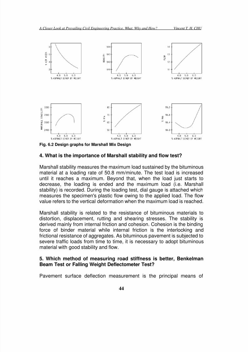
7/30/2019 A Closer Look at Prevailing Civil Engineering Practice
http://slidepdf.com/reader/full/a-closer-look-at-prevailing-civil-engineering-practice 44/83
A Closer Look at Prevailing Civil Engineering Practice, What, Why and How? Vincent T. H. CHU
44
Fig. 6.2 Design graphs for Marshall Mix Design
4. What is the importance of Marshall stability and flow test?
Marshall stability measures the maximum load sustained by the bituminousmaterial at a loading rate of 50.8 mm/minute. The test load is increaseduntil it reaches a maximum. Beyond that, when the load just starts to
decrease, the loading is ended and the maximum load (i.e. Marshallstability) is recorded. During the loading test, dial gauge is attached whichmeasures the specimen's plastic flow owing to the applied load. The flowvalue refers to the vertical deformation when the maximum load is reached.
Marshall stability is related to the resistance of bituminous materials todistortion, displacement, rutting and shearing stresses. The stability isderived mainly from internal friction and cohesion. Cohesion is the bindingforce of binder material while internal friction is the interlocking andfrictional resistance of aggregates. As bituminous pavement is subjected tosevere traffic loads from time to time, it is necessary to adopt bituminous
material with good stability and flow.
5. Which method of measuring road stiffness is better, BenkelmanBeam Test or Falling Weight Deflectometer Test?
Pavement surface deflection measurement is the principal means of

7/30/2019 A Closer Look at Prevailing Civil Engineering Practice
http://slidepdf.com/reader/full/a-closer-look-at-prevailing-civil-engineering-practice 45/83
A Closer Look at Prevailing Civil Engineering Practice, What, Why and How? Vincent T. H. CHU
45
evaluating a flexible pavement structure because the magnitude and shapeof pavement deflection is a function of traffic, pavement structure,temperature and moisture affecting the pavement structure. Deflectionmeasurements can be used in back calculation method to determine the
stiffness of pavement structural layers.
The Benkelman Beam measures the static deflection s and it is operated onthe basis of lever arm principle. Measurement is made by placing the tip ofthe beam between the dual tires and measuring the pavement surfacerebound as the truck is moved away. The test is of low cost but it is timeconsuming and labour intensive in carrying out the test.
In Falling Weight Deflectometer Test, the falling weight deflectometer ismounted in a vehicle. The sensors are lowered to the pavement surfaceand the weight is dropped. The test measures the impact load response offlexible pavement. It has the potential advantages that it is quick to performand the impact load can be readily changed. Moreover, the impact action offalling weight appears to be more accurately representing the transientloading of traffic.
6. What is the importance of friction course to expressways and highspeed roads?
Friction course, which is known as porous asphalt, is often used as surfacematerial in high speed roads and expressway. It is porous in nature which
allows for speedy drainage of surface water. Road safety can be improvedbecause it reduces the chance of hydroplaning/aquaplaning (i.e. there is alayer of water between the tires of the vehicle and the road surface. It maylead to the loss of traction and thus prevent the vehicle from responding tocontrol inputs such as steering, braking or accelerating). It also decreasesthe splash and spray from vehicles in wet weather. It serves as a drainagechannel for water to flow beneath the pavement surface.
Friction course has larger texture depth and this enhance improved skidresistance for vehicles traveling at high speed. It also has other benefitslike the reduction of noise generated by vehicle tyres.
7. For a concrete pavement constructed over a box culvert, why is itimportant to match the location of transverse joints with boundary ofbox culvert?
When a concrete pavement is constructed over a box culvert, it is important

7/30/2019 A Closer Look at Prevailing Civil Engineering Practice
http://slidepdf.com/reader/full/a-closer-look-at-prevailing-civil-engineering-practice 46/83
A Closer Look at Prevailing Civil Engineering Practice, What, Why and How? Vincent T. H. CHU
46
to match the location of transverse joints with boundary of box culvert.Otherwise, it is likely that full-depth transverse cracks would develop on thepavement slabs just above the location of boundary of box culvert. In casea layer of granular sub-base is introduced to place under the pavement
slabs, the sub-base layer serves as crack-arresting layer and the possibilityof development of transverse cracks in concrete pavement is reduced.
8. Is the skid resistance of bituminous pavement derived frommicrotexture of aggregates or texture depth of road surface?
The skid resistance of road surface is of paramount importance inenhancing road safety. The chance of occurrence of skidding is reducedwith an increase of skid resistance.
At low traffic speed (i.e. 50km/hr), the skid resistance is mainly controlledby microtexture of bituminous aggregates. For road speed exceeding50km/hr, the macrotexture of road surface comes into play which ischaracterized by texture depth of pavement. Hence, surface texturebecomes an important parameter when designing high speed roads andexpressway. The typical texture depth for concrete carriageway is 0.7mm.However, to maintain skid resistance provided by 0.7mm texture depth ofconcrete carriageway, 1.5mm texture depth is required for bituminouspavement in high speed road.
9. Why do some countries have reservation on the use of friction
course as bituminous surface layers?
Owing to the porous nature of friction course, its deterioration rate is fasterthan conventional bituminous materials and the durability of friction courseis a main concern form users. The service life of friction course is reportedto be around 8-10 years.
The main durability problem of friction course is associated with raveling offriction course and stripping of underlying layers. Raveling of friction courseoccurs as a result of lack of cohesion between aggregates. Stripping ofunderlying layers is attributed by inadequate drainage of water through the
friction course. With the use of polymer in friction course, it permits the useof higher air void (allows for better drainage) and higher binder content.

7/30/2019 A Closer Look at Prevailing Civil Engineering Practice
http://slidepdf.com/reader/full/a-closer-look-at-prevailing-civil-engineering-practice 47/83
A Closer Look at Prevailing Civil Engineering Practice, What, Why and How? Vincent T. H. CHU
47
10. What are the causes of longitudinal cracks and transverse cracksin bituminous pavement?
Longitudinal cracks in bituminous pavement are usually caused by fatigue
failure under repeated traffic loading. In thin pavements, cracking starts atthe bottom of the bituminous layer where the tensile stress is the highestand then it spreads to the surface as one or more longitudinal cracks. Inthick pavements, the cracks usually commence from the top because ofhigh localized tensile stresses from tire-pavement interaction. Afterrepeated loading, the longitudinal cracks develop into a pattern similar tothe back of an alligator.
Transverse cracks are usually formed as a result of thermal movement. Itmay occur because of shrinkage of the bituminous surface due to lowtemperatures or asphalt binder hardening.
11. Which of the following cause much damage to bituminouspavement?
(a) Low usage by heavy vehicles or frequent usage of lightvehicles;
(b) Low speed traffic or high speed traffic
The relationship between axle weight and the associated pavementdamage is not linear but exponential. The pavement damage caused byone passage of a fully loaded tractor-semi trailer (80kN) is more than 3,000
passages of private cars (9KN). Hence, heavy trucks and buses areresponsible for a majority of pavement damage.
Slow-moving traffic imposes greater damage than fast-moving traffic. Paststudies showed that when the speed is increased from 2km/hr to 24km/hr,the stress and pavement deflection is reduced by 40%.
12. What are the differences between tensioned corrugated beam anduntensioned corrugated beam?
Tensioned corrugated beam is mainly used in high speed road while
untensioned corrugated beam is mainly used in low speed road.
Tensioned corrugated beam is designed mainly for use on centralreservation. When a vehicle crashes into tensioned corrugated beam, thebeam remains in tension while the post gives way to allow for deformation.Tensioned corrugated beam absorbs impact energy by deflecting as a

7/30/2019 A Closer Look at Prevailing Civil Engineering Practice
http://slidepdf.com/reader/full/a-closer-look-at-prevailing-civil-engineering-practice 48/83
A Closer Look at Prevailing Civil Engineering Practice, What, Why and How? Vincent T. H. CHU
48
whole and helps the vehicle decelerate, and at the same time guide it backtowards the carriageway in a gradual and controlled manner. Tensionedcorrugated beam is normally not used on curves with radius less than120m.
Untensioned corrugated beam is commonly used for road bends whereradius of curvature is small as the use of untensioned beam does notrequire tensioning device. It is designed to deform in beams and tore-direct impacting vehicles on a course as close as possible parallel to thebarrier.
13. When are the conditions which warrant the installation of safetybarriers along roads?
In general there are several main conditions which warrant the installationof safety barriers along roads:
(i) It protects vehicles from hitting a roadside object (e.g. bridge pier,sign post, walls etc). Conversely, it protects the roadside object fromdamage by collision of vehicles.
(ii) It avoids the crossing over of vehicles over central median.(iii) It protects the vehicle from falling down a steep slope (more than 3m
high)(iv) A poor record of accidents involving run-off vehicles.
14. How do steel beam barriers (e.g. tension/untensioned beambarrier and open box barrier) function to contain vehicles uponcrashing?
Steel beam barrier consists mainly of horizontal rails and vertical posts.When a vehicle hits the steel beam barrier, the kinetic energy is resolved inthree components, namely vertical, normal to barrier and parallel to barrier.The vertical and normal components of kinetic energy are dissipatedthrough deformation and bending of beam and supporting posts. As such,the remaining component (i.e. parallel) guides the vehicle back to thecarriageway in a direction parallel to the barrier.
15. What is the significance of bleeding in bituminous pavement?
Bleeding occurs in bituminous pavement when a film of asphalt binderappears on road surface. Insufficient air void is a cause of bleeding inwhich there is insufficient room for asphalt to expand in hot weather and it

7/30/2019 A Closer Look at Prevailing Civil Engineering Practice
http://slidepdf.com/reader/full/a-closer-look-at-prevailing-civil-engineering-practice 49/83
A Closer Look at Prevailing Civil Engineering Practice, What, Why and How? Vincent T. H. CHU
49
forces its way to expand to pavement surface. Too much asphalt binder inbituminous material is also a common cause of bleeding. Bleeding is anirreversible process (the bleeded asphalt on pavement surface would notwithdraw in winter) so that the amount of asphalt binder on pavement
surface increases with time.
Bleeding forms a sticky and shiny surface which results in the loss of skidresistance for vehicles in wet weather.
16. Why is anti-skid dressing sometimes applied to pavementsurface?
Skid resistance of road pavement plays an importance role when vehiclestake a bend or brake. The use of anti-skid dressing increases the friction toreduce the possibility of skidding. Anti-skid dressing refers to the roadsurface treatment which includes high-friction calcined bauxite as the highPolished Stone Value artificial aggregate, together with a resin (epoxy,polyurethane) instead of bitumen to tie the aggregate to the road surface. Itis more expensive but is more durable in difficult sites such as crossing androundabout. Moreover, it also has side benefits of good acoustic quality.
Anti-skid dressing has normally a different colour to the road surface andused to be red in colour. Anti-skid dressing is commonly used in areaswhich require higher friction values such as approach to roundabouts andtraffic lights.
The ability of the road surface to resist skidding is a combination of thesurface texture of the road surface and the Polished Stone Value of theaggregate in the road surface. The higher the Polished Stone Value thehigher resistance the aggregate has to polished, and hence the greater thecapability the aggregate of retaining its own texture. Surface texture of theroad surface is often referred to as macrotexture while texture actually onthe surface of the aggregate is known as microtexture.
17. What is the purpose of road studs in roads?
In nighttime, car drivers could not see where the road ends and where thealignment of road changes in direction. Without sufficient number of roadlightings, it is necessary to provide some means to guide the drivers alongdark roads. Hence, in 1933 Percy Shaw invented the cat’s eye (i.e. roadstuds) which is based on the principle of cat’s eyes. When a ray of lightenters the eyes of a cat, the light shall be reflected back towards to the

7/30/2019 A Closer Look at Prevailing Civil Engineering Practice
http://slidepdf.com/reader/full/a-closer-look-at-prevailing-civil-engineering-practice 50/83
A Closer Look at Prevailing Civil Engineering Practice, What, Why and How? Vincent T. H. CHU
50
emitting source. As such, with the reflection of car’s headlights by roadstuds, it is possible to identify road conditions and alignment in darkness.
However, the provision of cats’ eye is not without problem. For instance,
there have been reported accidents arising from loosely installed cat’s eye.Some new design of cat’s eye uses LEDs which flash at about 100 timesper second. However, it is claimed to cause epileptic fits of drivers.
18. Why should edge courses of paving blocks sit on concretebedding?
In pavement made up of paving blocks, the edge courses are normallydesigned to sit on concrete bedding and haunching. The reason of suchprovision is to prevent lateral movement of paving blocks when subjectedto traffic loads. In essence, the edges formed by edge courses tie the bodyof the paving blocks as a single unit and they have to rely on concretebedding and haunching to resist the sideway forces generated by movingtraffic.
The concrete bed serves to keep the edge courses in position for surfacelevel and it provides the dead loads in the retaining structure. On the otherhand, concrete haunching also holds the edge courses in position from thepoint of view of lateral movement.
Fig. 6.3 Edge courses in paving blocks
19. What is the purpose of edge courses in paving blocks pavement?
The principal function of edge courses is to form a retaining structure withconcrete bedding and haunching to resist sideway movement arising fromtraffic loads. Other functions of edge courses include:
(i) It serves as level guides when carrying out screeding of sandbedding.

7/30/2019 A Closer Look at Prevailing Civil Engineering Practice
http://slidepdf.com/reader/full/a-closer-look-at-prevailing-civil-engineering-practice 51/83
A Closer Look at Prevailing Civil Engineering Practice, What, Why and How? Vincent T. H. CHU
51
(ii) It aids in the cutting of paving blocks near edge courses becausepaving blocks could lie over edge courses and the positions ofcutting could be marked accurately without any difficulty. However, ifa wall instead of edge courses is located adjacent to the pavement,
it is practically difficult to position the paving block over the gapbecause of the physical hindrance of the wall.
(iii) It could be designed as surface drainage channel to conveystormwater to a discharge point.
(iv) It acts as a frame which defines the shape of pavement.
20. For compaction of paving blocks, should the jointing sand beapplied before or after the compaction process?
The common practice is to apply jointing sand at the first place followed bysubsequent compaction. However, there are several potential problemsassociated with this method. Firstly, the presence of sand provides supportto paving blocks leading to inadequate compaction. Secondly, the excess jointing sand may be crushed during compaction and leaves stains on thesurface of paving blocks. Thirdly, damaged paving blocks appear to bedifficult for removal owing to frictional grip by jointing sand.
The alternative method is to carry out compaction firstly and then followedby application of joint sand and then re-compaction is carried out again.This method eliminates all the shortcomings of the first method describedabove. However, it suffers from the demerit of two passes of compaction
instead of a single stage of compaction is required. Moreover, thecompaction operation tends to be noisier because of the absence of theinfilling sand which helps to reduce noise level. The direct contact betweenindividual paving blocks is more vulnerable to spalling during compaction.
21. Can the sand bedding be omitted in paving block pavement?
In the paving block pavement, it normally consists of the following mainelements: sub-base, sand bedding and paving blocks. Sub-base is themain structural element to take up traffic load and spread it into larger areaso that the traffic stress is small enough for subgrade to sustain. Sand
bedding is used for providing correct line and level for paving blocks to lieon. To achieve this, screeding of bedding layer is implemented so that thepaving blocks could be laid directly on it without the need of further leveling.The large range of particle sizes associated with sub-base renders itunsuitable to provide a uniform surface with correct level for paving blocksto lie on.

7/30/2019 A Closer Look at Prevailing Civil Engineering Practice
http://slidepdf.com/reader/full/a-closer-look-at-prevailing-civil-engineering-practice 52/83
A Closer Look at Prevailing Civil Engineering Practice, What, Why and How? Vincent T. H. CHU
52
22. What is the difference between safety fence and safety barrier?
A safety fence is intended to absorb some energy caused by hitting
vehicles and to realign the vehicles to move parallel to the safety fence.
A safety barrier is intended to provide containment instead of energyabsorption upon hit by vehicles. Hence, it is anticipated to have littledeflection and deformation only. After crashing, it serves to re-direct thevehicles along the line of barrier.

7/30/2019 A Closer Look at Prevailing Civil Engineering Practice
http://slidepdf.com/reader/full/a-closer-look-at-prevailing-civil-engineering-practice 53/83
A Closer Look at Prevailing Civil Engineering Practice, What, Why and How? Vincent T. H. CHU
53
Chapter Chapter Chapter Chapter 7 77 7. . . . Slope Slope Slope Slopes ss s and and and and Excavation Excavation Excavation Excavation
1. In braced excavation, why is Rankine’s theory of lateral earth
pressure not applicable?
In braced excavation, sheetpiling is constructed at the first place, followedby the installation of struts as excavation proceeds. Following theinstallation of first row of struts, the depth of excavation is small so thatthere is no major yielding of soils. However, as further excavation takesplace, soils yield before the installation of n th row of struts. The first row ofstruts prevents yielding near the ground surface. As such, deformation ofwall increases with depth with the smallest at the ground level. Owing tothe effect of construction method of braced excavation, it differs from thedeformation condition of Rankine’s theory. This is attributed to arching
effects in which there exists upward redistribution of loads. The upper partof braced excavation is in the state of elastic equilibrium while the lowerpart is in the state of plastic equilibrium.
2. How could counterforts in counterfort retaining wall assist inresisting earth pressure?
Counterforts are used for high walls with height greater than 8 to 12 m.They are also used in situations where there is high lateral pressure, i.e.where the backfill soils are heavily surcharged.
The counterforts tie the base slab and wall stem together and they act astension bracing which strengthen the connection between wall and baseslab. The counterforts help to reduce bending moment and shear forcesinduced by soil pressure to the retaining wall. Moreover, it also serves toincrease the self-weight of the retaining wall which adds stability to theretaining wall.
3. What is the basic mechanism of soil nails in improving soilstability?
Soil nails improve slope stability by:
(i) Partial increase the normal force and shear resistance alongpotential slip surface in frictional soils.
(ii) Direct reduction of driving force along potential slip surface forcohesive and frictional soils.

7/30/2019 A Closer Look at Prevailing Civil Engineering Practice
http://slidepdf.com/reader/full/a-closer-look-at-prevailing-civil-engineering-practice 54/83
A Closer Look at Prevailing Civil Engineering Practice, What, Why and How? Vincent T. H. CHU
54
(iii) Soil nail head and facing provides containment effect to limit thedeformation near slope surface.
Soil nail head serves to provide reaction in mobilizing tensile force in soil
nail. Moreover, it provides confinement to soils in active zone behind soilnail head and avoids the occurrence of local failure between adjacent soilnails.
4. What is the purpose of installation of erosion control mat inslopes?
Steep slopes are prone to intermittent high velocity flows during rainstormand this causes erosion at slope surface which prevents the growth ofvegetation.
Erosion control mat is installed to control soil erosion and provide soilstability until vegetation can be established. The principal function oferosion control mat is to prevent pre-vegetated soil loss by stabilizing andprotecting soils from rainfall and surface erosion. Moreover, it could providea long-term artificial erosion control system which would increase the shearresistance of vegetation and provide long-term, tenacious reinforcement ofthe root system.
5. For Peck’s pressure envelope for braced excavation, should totalweight or effective weight be used in rectangular and trapezoidal
envelope?
The use of active and at-rest theory is not applicable in braced excavation.In essence, upper struts tend to be more heavily loaded while lower strutsappear to be less loaded when compared with active pressure theory.
Peck then measured the bracing loads which were converted back to soilpressures. For example, the pressure envelope for non-cohesive soils is0.65r HKa (r =soil density, H=height of excavation and Ka=active pressurecoefficient).
Some engineers consider r as total soil weight without applying any waterpressure. However, Peck has said “the earth pressures are essentiallyeffective active pressures multiplied by a factor and redistributed as arectangle or a trapezoid.” Hence, effective weight of soils should be usedfor r with water pressures added separately.

7/30/2019 A Closer Look at Prevailing Civil Engineering Practice
http://slidepdf.com/reader/full/a-closer-look-at-prevailing-civil-engineering-practice 55/83
A Closer Look at Prevailing Civil Engineering Practice, What, Why and How? Vincent T. H. CHU
55
6. What is the difference between sprigging and turfing?
A sprig is a part of stem with crowns and roots which is cut from a rhizomeor stolon. Sprigging is a type of vegetative planting by placing sprigs in
spaced intervals in holes. With proper transplantation and maintenance, asprig is capable of growing as a plant. The cost of sprigging is moderateand vegetation is expected to grow for around six months. However, thismethod requires high manual input and is labour intensive.
Turfing is the direct application of vegetation with developed roots. Thecost of turfing is high when compared with sprigging. However, it is thequickest way to get vegetation. Within a month mature-looking vegetationis ready for use.
7. How can concrete buttress stabilize rock fall?
Sometimes there is a cavity in rock slopes which is caused by previousrock falls. Concrete buttress, together with the use of rock dowels, couldhelp to stabilize the rock slope.
The buttress serves to avoid local toppling of rock face. Moreover, it keepsprotects the unstable rock and keep it in place. The presence of buttressalso helps hold up the overhang. The size of buttress should be largeenough to support the weak rock. In case the surface on which the buttressis founded is not normal to the resultant forces exerting on the buttress,
buttress is tied to rock surface by using rock dowels to avoid theoccurrence of sliding.
8. Should high preloads be adopted in struts in braced excavation?
Preloading in struts in braced excavation helps eliminate the potentialmovement. The application of preload decreases the shear stress in soilsestablished previously by excavation. As a result of stiffening of soils, thesoil movement is declined accordingly.
However, the use of very high preloads in struts may not be desirable
because the local outward movement at struts may cause damage tonearby utilities.

7/30/2019 A Closer Look at Prevailing Civil Engineering Practice
http://slidepdf.com/reader/full/a-closer-look-at-prevailing-civil-engineering-practice 56/83
A Closer Look at Prevailing Civil Engineering Practice, What, Why and How? Vincent T. H. CHU
56
9. What is the significance of free length and fixed length in tiebacksin anchored excavation?
The use of tiebacks in deep excavation allows uninterrupted earth moving
within the excavation zone owing to the absence of interior obstructions.The spacing of tieback should not be placed too close as this may impairthe capacity of tieback because of the interference between adjacentgrouted zones.
A tieback is made first by drilling a hole by a drill rig, followed by placing abar in the drilled hole. Concrete is then poured in the hole and theconnection of tieback with wall is made lastly. A tieback anchor consists ofan anchorage located in a bearing layer and the anchor is tensioned at thefront face of the wall. The portion of the anchor which transmits the force tothe surrounding soil is called the "fixed length". One the other hand, the"free length" of tieback transfers the force from the fixed length through theanchor head to the wall.
Fig. 7.1 Free length and fixed length in tieback
10. What is the typical proportioning of a retaining wall?
The base slab thickness of a cantilever retaining wall is about 10% of thetotal height of retaining wall. The length of base slab is about 50-70% of thetotal height of retaining wall. Generally speaking, the thickness of wallstems may vary along the stem provided that its size should not be less
than 300mm to facilitate concrete placement.
For retaining wall with a total height exceeding 8-12m, it is recommendedto adopt counterfort retaining wall. The counterforts in counterfort retainingwall are normally spaced at about 30% to 70% of the total height. Thelength of base slab is about 40-70% of the total height of retaining wall.

7/30/2019 A Closer Look at Prevailing Civil Engineering Practice
http://slidepdf.com/reader/full/a-closer-look-at-prevailing-civil-engineering-practice 57/83
A Closer Look at Prevailing Civil Engineering Practice, What, Why and How? Vincent T. H. CHU
57
11. What is the reason of adding steel wire mesh when using erosioncontrol mat in slopes?
It is not uncommon that the use of erosion control mat in slopes is
accompanied by the addition of steel wire mesh. The system of erosioncontrol mesh with a steel wire mesh proves to be a more effective methodto control surface erosion. In case surface erosion occurs even in thepresence of erosion control mat, the soil debris could be trapped betweenthe steel wire mesh and the slope surface. As such, the steel wire meshessentially serves as an additional protective layer to avoid furtheroccurrence of erosion.
12. What are the applications of diagonal strutting and long flyingshores in braced excavation?
Diagonal strutting is sometimes used at the corners of excavation to leavea large working space at excavation level.
Sometimes, raking struts are observed in long flying shores acrossexcavation and these struts serve to decrease the span length of struts.
Fig. 7.2 Diagonal strutting and long flying shores in braced excavation
13. Is force and moment equilibrium satisfied by Janbu’s method,Bishop’s method and Morgenstern-Price method?
Janbu’s method and Morgenstern-Price method are non-circular analyticalmethod and they are frequently used for soil slopes while Bishop’s methodis circular analytical method. Bishop’s Simplified method and Janbu’s

7/30/2019 A Closer Look at Prevailing Civil Engineering Practice
http://slidepdf.com/reader/full/a-closer-look-at-prevailing-civil-engineering-practice 58/83
A Closer Look at Prevailing Civil Engineering Practice, What, Why and How? Vincent T. H. CHU
58
Simplified method assume that the inter-slice forces are horizontal andinter-slice shear forces are neglected.
Force EquilibriumEquilibrium Method MomentEquilibrium Horizontal Vertical
Janbu’s Simplified No Yes YesBishop’s Simplified Yes No YesMorgenstern-Price Yes Yes Yes

7/30/2019 A Closer Look at Prevailing Civil Engineering Practice
http://slidepdf.com/reader/full/a-closer-look-at-prevailing-civil-engineering-practice 59/83
A Closer Look at Prevailing Civil Engineering Practice, What, Why and How? Vincent T. H. CHU
59
Chapter Chapter Chapter Chapter 8 88 8. . . . Tunneling Tunneling Tunneling Tunneling
1. How can Earth Pressure Balance TBM maintain stability of tunnel
face?
Earth Pressure Balance (EPB) TBMs are used in excavating andadvancing tunnels through any type of soft ground or soil condition,particularly below the water table. The EPB method consists of a cuttingchamber located behind the cutterhead. This chamber is used to mix thesoil with water foam. It is maintained under pressure by the muckingsystem. The ground at the cutting face is supported by earth pressure bybalancing the advancement of the tunnel with the discharge rate of theexcavated soil.
The underlying principle of the EPB method is that the excavated soil itselfis used to provide continuous support to the tunnel face by balancing earthpressure against the forward pressure of the machine. The thrust forcesgenerated from rear section of TBM is transferred to the earth in thecutterhead chamber so as to prevent uncontrolled intrusion of excavatedmaterials into the chamber. When the shield advances at the face ofexcavation, the excavated soil is then mixed together with a special foammaterial which changes its viscosity or thickness and transforms it into aflowing material. This muck is then stored and is used to provide supportand to balance pressure at the tunnel face during the excavation process.
2. Why do Slurry Shield TBMs have difficulty when tunneling in clay?
In Slurry Shield TBMs, the slurry forms a filter cake on the face ofexcavation which has the following purposes:
(i) It provides the surface for slurry pressure to act on.(ii) It acts as a seal against the y of groundwater into the tunnel.(iii) In case the TBM breaks down, this filter cake serves as a sealing
membrane at the tunnel face which allows man-entry into theexcavation and working chamber upon provision go compressed air.
Slurry Shield TBMs are widely used for non-cohesive soils ranging fromfine-grained sand to coarse-grained gravel. It is less suitable whenoperating in clay because:
(i) Most slurry separation plant could not separate clay from slurry. As

7/30/2019 A Closer Look at Prevailing Civil Engineering Practice
http://slidepdf.com/reader/full/a-closer-look-at-prevailing-civil-engineering-practice 60/83
A Closer Look at Prevailing Civil Engineering Practice, What, Why and How? Vincent T. H. CHU
60
such, the cost of frequent replacement of bentonite slurry issubstantially increased.
(ii) Clayey materials to clog and cause blockages in slurry systemleading to sudden pressure surges.
3. Should closed-end or open-end pipes be used in pipe ramming?
It is more common to adopt open-end pipes in pipe ramming because it isnot readily to undergo surface heaving or pipe deflection when comparedwith closed-end pipes. Moreover, the use of open-end pipes requires lowerramming force.
Closed-end pipes are only used in the following conditions:
(i) Ground with poor self-support so that inflow of soils inside the pipeswould render ground settlement and loss of support to utilityservices.
(ii) Small size of pipes.
4. What is the difference between “cut-and-cover” method and“cover-and-cut” method in tunnel construction?
“Cut-and-cover” method involves the construction of open cut at the firstplace, followed by the construction of tunnels under open excavation. Uponcompletion of the structure, backfilling and reinstatement would besubsequently carried out.
“Cover-and-cut” method involves firstly the construction of cover followedby the second stage in which construction activities are carried out underthe cover. As such, the disturbance to the public owing to constructionalactivities could be reduced to a minimum.
5. Would pipe ramming increase the vertical soil loads on installedpipes?
Consider a certain cross section along the line of pipe ramming. When thepipe is rammed close to the cross section, the horizontal and vertical soilpressure would increase owing to the effect of soil compaction broughtabout by dynamic ramming operation. Upon reaching the cross section,soil pressure is redistributed around the pipe such that the vertical pressureabove the pipes is reduced while the vertical pressure in pipe abutment

7/30/2019 A Closer Look at Prevailing Civil Engineering Practice
http://slidepdf.com/reader/full/a-closer-look-at-prevailing-civil-engineering-practice 61/83
A Closer Look at Prevailing Civil Engineering Practice, What, Why and How? Vincent T. H. CHU
61
locations is increased. When the pipe is advanced further, the load onpipes tend to increase owing to reorientation of soils around pipe wall.Finally, when the pipe is rammed some distance away from the crosssection, a stable state is achieved in which there is smaller earth pressure
on the pipe’s top and higher vertical soil pressure on soils at both sides ofthe pipe.
6. What are the situations which warrant the use of pipe ramminginstead of other trenchless methods?
There are two main distinct advantages of pipe ramming:
(i) Settlement and heaving of existing ground.Where a pipe have to be installed under an existing railway orheavily-trafficked highway, it is almost impossible to install the pipesby open excavation. In particular, if the pipes to be installed are ofshallow depth, the use of some trenchless methods (e.g. pipe jackingand heading) may cause considerable ground settlement because thesoil loss within shallow zone would induce larger settlement. As such,the use of pipe ramming could resolve this concern. Pipe ramming isa displacement method which generally would not result in groundloss. For open-ended steel casing, the soils inside the pipe are notremoved until the entire casing is installed in place.
(ii) Muck Disposal
For microtunneling, spoils are removed from the excavation face in aslurry so that the spoil are wet. Hence, sufficient space has to beprovided to allow for drying of spoils or the wet spoils have to beremoved off site immediately. For pipe ramming slurry is not used sothat the spoil retains only it natural moisture content. Therefore, it iseasier to handle in-situ soils than wet spoils. On the other hand, theamount of spoil produced by pipe ramming is smaller when comparedwith pipe jacking and microtunneling.
7. What is the difference between close mode, open mode and mixedmode of trenchless methods?
(i) Close modeIt refers to mechanically operated TBM using bulkhead or slurry tobalance earth pressure and groundwater. There is no manual accessto the face of excavation.

7/30/2019 A Closer Look at Prevailing Civil Engineering Practice
http://slidepdf.com/reader/full/a-closer-look-at-prevailing-civil-engineering-practice 62/83
A Closer Look at Prevailing Civil Engineering Practice, What, Why and How? Vincent T. H. CHU
62
(ii) Open modeIt refers free air hand-dug tunnel or compressed air handing tunnelingwith manual access to face of excavation.
(iii) Mixed mode
It is similar to close mode except that it allows access to the face ofTBM for manual removal of obstructions.
8. Why does settlement occur in microtunneling?
Settlements occur in microtunneling, or other tunnel construction methodsin two forms: large settlements and systematic settlements. The cause oflarge settlements is the over-excavation by microtunneling machineleading to the loss of stability at the tunnel face and the formation of emptyspace above the tunnel. The occurrence of large settlements is attributedto the improper operation of the tunneling machine or rapid unexpectedchanges in ground conditions.
Systematic settlements are mainly caused by the collapse of the radialovercut between the jacking pipe and the excavation. The annular spacebetween the jacking pipe and the excavation is essential in microtunnelingand pipe jacking for the following purposes:
(i) Reduction of jacking forces(ii) Injection of the lubrication(iii)Steering of the microtunneling boring machine
During tunneling, the soils may collapse onto the pipe, resulting insubsidence at the ground surface. Systematic settlements can becontrolled by limiting the radial overcut and by filling the annulus withbentonite lubricant during tunneling, and with cement grout after tunnelingis completed.
9. How could ground freezing stop ingress of groundwater inexcavation?
The concept of ground freezing involves the lowering of temperature of
ground near the excavation area. Drillholes with designed spacing areinstalled so that a chilled brine or liquid nitrogen is introduced into the holes.Brine requires continuous circulation while liquid nitrogen is for rapidfreezing and it is unrecoverable. With the addition of a chilled brine or liquidnitrogen, the groundwater is frozen into ice. Upon frozen, soils exhibithigher shear strength and the frozen zone acts as an impermeable barrier

7/30/2019 A Closer Look at Prevailing Civil Engineering Practice
http://slidepdf.com/reader/full/a-closer-look-at-prevailing-civil-engineering-practice 63/83
A Closer Look at Prevailing Civil Engineering Practice, What, Why and How? Vincent T. H. CHU
63
so that water could not enter the excavation zone.
10. Does microtunneling refer to tunnel size less than 1,000mm?
The international definition of microtunneling includes pipe with diameterup to 1,000mm only. However, in the United States, it allows for larger pipesize when defining microtunneling in which pipe with diameters up to 144inches are also counted within the ambit of microtunneling.
The basic concept of microtunneling has changed gradually owing torecent technological developments and past experience. For instance, theuse of alignment control system with advanced surveying techniquesallows for longer drives with good control and curved microtunneling. Theuse of automatic lubrication system enhances lower jacking forces. Theemployment of gripper in microtunneling machines helps developadequate loads on cutter discs for cutting rock.
11. What are the situations which warrant the use of microtunnelinginstead of other trenchless methods?
There are two main advantages of microtunneling:
(i) Difficult ground conditionsMicrotunnels could operate under a water head of 30m or more. It iscapable of handling a wide range of soils such as cobble, boulders
and rock without the need of dewatering.
(ii) Surface settlementSurface settlement could be minimized by using microtunneling. Forexample, the use of earth pressure balance method in microtunnelinghelps balance the external soil loads and groundwater. Moreover, therate of advancement of machine and the rate of excavation of tunnelface can be readily controlled so that it reduces the occurrence ofover-excavation at tunnel face and hence the ground settlement.
12. What is the difference between single shield and double shield
tunnel boring machine (TBM)?
In single shield TBM, it extends and moves forward by thrust cylinders onthe last segment ring installed.
In double shield TBM, it consists of an extendable front shield which

7/30/2019 A Closer Look at Prevailing Civil Engineering Practice
http://slidepdf.com/reader/full/a-closer-look-at-prevailing-civil-engineering-practice 64/83
A Closer Look at Prevailing Civil Engineering Practice, What, Why and How? Vincent T. H. CHU
64
enhances the cutterhead to be extended. The gripper in the middle sectionof TBM is mobilized so that it pushes against the tunnel walls to react theboring forces. As these forces are dissipated, it allows the installation oflining segments during tunnel so that it increases the speed of tunneling.
Upon completion of a trust stroke, the grippers are retracted and the endportion of TMB is pushed against the front shield by thrust cylinders.
Double shielded TBM is normally used in rock strata with geological faultzones and when a high rate of advancement is required. Single shieldedTBM is more suitable to hard rock strata.
13. In Slurry Shield TBMs, should high or low slurry pressure bemaintained to support excavated face?
In Slurry Shield TBMs, the slurry supports the wall of tunnel face in amanner similar to diaphragm wall. The bentonite forms a filter cake on thetunnel face on which the slurry exerts its pressure.
The face of a slurry shield tunnel boring machine is stabilized by bentoniteslurry, which is kept under pressure. If the slurry pressures provided are toolow, instability of the face results with occurrence of large settlements. Onthe contrary, in case the slurry pressures are kept too high, it leads to anexcessive loss of bentonite and significant soil disturbance would occur.
14. Is NATM a tunneling method or a tunneling concept?
In the original version of the New Austrian Tunneling Method, it is atunneling concept with a set of main principles as follows:
(i) Application of thin-spayed concrete lining(ii) Closure at invert to form a complete ring as soon as possible(iii) Measurement of deformation until equilibrium is attained
It is a design concept in which the ground (soil or rock) enclosing theopening becomes a load-bearing element through formation of ring-like
body. It uses all available means to develop maximum self-supportingcapacity to provide support of the underground opening. In essence, itmakes use of geological stress of surrounding soils to stabilize the opening.Therefore, NATM is a tunneling philosophy and concept rather thanexcavation techniques.

7/30/2019 A Closer Look at Prevailing Civil Engineering Practice
http://slidepdf.com/reader/full/a-closer-look-at-prevailing-civil-engineering-practice 65/83
A Closer Look at Prevailing Civil Engineering Practice, What, Why and How? Vincent T. H. CHU
65
15. What is the difference between NATM and Sprayed ConcreteLining?
The New Austrian Tunneling Method originated from rock tunnels and it
requires the use of rockbolts and shotcrete swiftly after blasting. Institutionof Civil Engineers has renamed it as Sprayed Concrete Lining forconstruction of tunneling linings by this method in soft ground .
There are some distinct differences in design philosophy between NATMand Sprayed Concrete Lining. In fact, it is not practical to mobilize inherentsoil strength through deformation in soft ground. For lower strength of soilsin soft ground, there should not be any delay in completing primary supportand ground deformation should be reduced as much as possible.

7/30/2019 A Closer Look at Prevailing Civil Engineering Practice
http://slidepdf.com/reader/full/a-closer-look-at-prevailing-civil-engineering-practice 66/83
A Closer Look at Prevailing Civil Engineering Practice, What, Why and How? Vincent T. H. CHU
66
Chapter Chapter Chapter Chapter 9 99 9. . . . S SS Site Investigation ite Investigation ite Investigation ite Investigation
1. What is the difference between Dynamic Probing and StandardPenetration test?
Standard Penetration Test (SPT) is an in-situ dynamic penetration test toprovide information on the properties of soil. It may also collect a disturbedsoil sample for grain-size analysis and soil classification. SPT involves thedriving of a standard sampler through a distance of 450mm into the bottomof a borehole using the standard weight of 63.5kg falling through 760mm.
Dynamic Probing Test as per BS1377: Part 9: 1990 involves the driving ofa metal cone into the ground through a series of 1-metre length steel rods.
These rods are driven from the surface by the hammer system on the rigwhich drops 63.5 kg weight onto the rods through a fall of 760mm. Thenumber of blows that is required to drive the cone down each 100mmincrement is then recorded until a required depth is reached or a refusal isachieved. Dynamic Probing has many applications. For instance, it may beused to estimate the depths of at the interface between hard and soft strataand to trace the outline of objects buried underground.
SPT test is used to provide valuable information on soil properties.However, the main use of dynamic probing is to interpolate information between boreholes/trial pits swiftly and to supplement information found
from boreholes and trial pits at a low cost. For instance, dynamic probing iscarried out close to a borehole where the underground conditions areidentified. As such, by using the dynamic probing, the result of boreholecan be extended to other areas in between two boreholes.
2. What is the difference between trial pit, trial trench and inspectionpit?
A trial pit is used for obtaining information on the subsurface soil conditions.It allows logging of the various soils types and soil sampling. Typical size oftrial pits has minimum base plan area of 1.5m2. Trial trench serves the
same purpose of trial pit except that they differ in size and dimension. Forinstance, the length of a trial trench is normally larger than its width by acertain factor (e.g. 5) to cater for its “trench” shape.
An inspection pit is a pit used for identifying and positioning of undergroundutilities and structure.

7/30/2019 A Closer Look at Prevailing Civil Engineering Practice
http://slidepdf.com/reader/full/a-closer-look-at-prevailing-civil-engineering-practice 67/83
A Closer Look at Prevailing Civil Engineering Practice, What, Why and How? Vincent T. H. CHU
67
3. When would engineers use Cone Penetration Testing instead ofStandard Penetration Test?
(I) Standard Penetration Test is carried out in boreholes at 1.5-2m intervals.
However, Cone Penetration Testing allows a continuous record ofground resistance profile.
(II) Disturbance to ground is less by Cone Penetration Testing whencompared with Standard Penetration Test.
(III) The use of Cone Penetration Testing is faster and cheaper whencompared with the combination of boring, sampling and StandardPenetration Test.
4. How to identify sand and clay from the results of Cone PenetrationTesting?
Cone Penetration Testing measures the pressure at the end of cone (endresistance), friction on sleeve and pore water pressure. Friction ratio isdefined as the ratio of friction/end resistance.
For clay, typical CPT results exhibit low end resistance, high friction ratioand high pore water pressure.
For sand, typical CPT results exhibit high end resistance, low friction ratioand low pore water pressure.
5. What is the purpose of adding hydrogen peroxide in sedimentationanalysis?
There are two major techniques of particle size distribution:
(i) Sieve analysis – for soil particles larger than 60µm they can beseparated by this method.
(ii) Sedimentation analysis – for soil particles smaller than 60µm, theyare too small to be sieved by sieve analysis. Instead, the particlesize distribution is worked out from the rate of settlement of soilparticles suspended in water by Stoke’s law.
In sedimentation analysis, the soil under testing is firstly boiled with littledistilled water to wet and break up the particles. After that, hydrogenperoxide is added to remove any organic material . Then the whole mixtureis allowed to stand still for a night and then boiled again to removehydrogen peroxide.

7/30/2019 A Closer Look at Prevailing Civil Engineering Practice
http://slidepdf.com/reader/full/a-closer-look-at-prevailing-civil-engineering-practice 68/83
A Closer Look at Prevailing Civil Engineering Practice, What, Why and How? Vincent T. H. CHU
68
6. How can trial pits be made in slopes?
In slopes, trial pits are transformed into another method called slopesurface stripping. It involves the removal of slope surface protection and
vegetation to reveal the soil conditions below slope surface for inspectionpurpose. The strip is about 0.3m to 0.5m wide and 150mm to 300mm deepand it usually extends from the crest to the toe of slopes. Slope surfacestripping is commonly used in Hong Kong.
7. Multistage triaxial test may not be preferable for consolidateddrained test. Why?
In multistage consolidated drained test, the soil sample is consolidatedunder all round pressure and then loaded by applying an axial stress. Priorto failure, loading is stopped and the specimen is consolidated under ahigher confining pressure. The above steps are repeated for 3 stages toobtain the failure envelope.
The main problem associated with multistage consolidated drained test liesin the practical difficulty in determining the failure state of the soil sample.Judgment has to be made regarding the condition of “immediately prior tofailure” on stress strain curves. It is not uncommon that wrong estimation ofthe failure state occurs when interpreting the stress strain curves. Whenthere is an underestimation of deviator stress at failure, it would result inoverestimation of friction angle and underestimation of cohesion. In case
actual failure of soil samples occurs before visual recognition, the sampleundergoes overstressing so that the deviator stress at failure in later stagesis reduced. As such, this leads to overestimation of cohesion andunderestimation of friction angle.
8. Why is multiple packer test instead of single packer test sometimesadopted in testing permeability of rock?
Packer test is used in unlined drillholes in rock to test the permeability. Insingle packer test, the hole is drilled to the bottom of first test section andthe top of the test section is sealed off by a packer. Water is then delivered
to the test section and it is kept at constant pressure and the flow ismeasured.
In highly fractured rock there is a high chance that water tends to leakaround the packer which gives inaccurate result. As such, multiple packersare adopted instead in which three sections of the drillhole are sealed up

7/30/2019 A Closer Look at Prevailing Civil Engineering Practice
http://slidepdf.com/reader/full/a-closer-look-at-prevailing-civil-engineering-practice 69/83
A Closer Look at Prevailing Civil Engineering Practice, What, Why and How? Vincent T. H. CHU
69
and water is pumped to them at equal pressure. This eliminates thetendency for water to flow around the packers from the middle section.Hence, a more accurate result could be obtained by measuring flow fromthe middle section alone.
Fig. 9.1 Illustration of multiple packer test
9. Why is shear box test not a better alternative to triaxial test indetermining shear strengths of soils?
The test procedure is simpler for shear box test. However, it suffers fromthe demerit that drainage conditions are not easily controlled and pore
water pressure cannot be measured. Moreover, the plane of failure isgoverned by the test itself rather than the properties of soil. It is likely thatshear stress distribution across the soil sample is not uniform. The abovelimitations may affect the accuracy and reliability of test results.
One of the advantages of shear box is that the test could be continued tolarge strains so that residue shear strength could be determined. In fact,triaxial test has mostly replaced shear box test for normal application.

7/30/2019 A Closer Look at Prevailing Civil Engineering Practice
http://slidepdf.com/reader/full/a-closer-look-at-prevailing-civil-engineering-practice 70/83
A Closer Look at Prevailing Civil Engineering Practice, What, Why and How? Vincent T. H. CHU
70
Chapter Chapter Chapter Chapter 10 10 10 10. . . . Sewage and Waterworks Sewage and Waterworks Sewage and Waterworks Sewage and Waterworks
1. Why are some ductile iron pipes cement-mortar lined?
Cement mortar lining provides a high pH in the inner surface of ductile ironpipes and it serves as a physical barrier to water to guard against corrosionof iron from acidic water. Moreover, owing to smooth nature of cementlining, it results in the provision of high flow.
For cement-mortar lined ductile iron pipes to convey water, water infiltratesthe pores of lining and releases some calcium hydrate. The freed calciumhydrate form calcium carbonate with calcium bicarbonate in water so that itserves to clog the pores of linings and avoid further permeation of water.Moreover, iron also reacts with lime to precipitate iron hydroxide which also
seals the pores of linings. As such, the lining provides both chemical andphysical barrier to aggressive water.
2. In some countries like the United States, asphaltic seal-coat is usedin cement mortar lining of ductile iron pipes. Why?
The original intention of adding a thin asphaltic seal-coat on freshly placedcement-mortar lining is to reduce water loss during hydration so as toachieve better curing of the linings. In fact, it also helps hinder the leachingof cement by corrosive water. Otherwise, leachates from cement liningsmay cause a rise in pH in water.
However, asphaltic seal-coat is considered undesirable from environmentalpoint of view. The seal-coat material is solvent-based which containsvolatile organic compounds, which is an air pollutant.
3. What is the purpose of polyethylene encasement for ductile ironpipes?
The provision of polyethylene encasement avoids the direct contact ofductile iron pipes with surrounding aggressive environment. However,
polyethylene encasement is not intended as a water-tight system. Initiallymoisture between ductile iron pipes and polyethylene encasementcontains some oxygen which shall be ultimately depleted and this wouldput a stop to the oxidation reaction. This process leads to a stable andstagnant environment near the pipe and it provides a protectiveenvironment.

7/30/2019 A Closer Look at Prevailing Civil Engineering Practice
http://slidepdf.com/reader/full/a-closer-look-at-prevailing-civil-engineering-practice 71/83
A Closer Look at Prevailing Civil Engineering Practice, What, Why and How? Vincent T. H. CHU
71
4. What is the purpose of bolt tightening sequence in flanged joints?
Bolted flange joint is widely used in watermains. In essence, a bolt axialtension is applied by the torque control method. The preload values are
recommended by gasket suppliers to control gasket crushing and toachieve proper gasket seating stress. A proper bolt tightening sequence inflanged joints is essential to control stress variation in flange jointcomponents. Otherwise, leakage occurs at flanged pipe joints duringoperating conditions.
Most joint surface of joints is not completely flat. The sequence of bolttightening exerts a huge effect on the resulting preloads. Since jointscontaining gaskets have a comparatively low compressive stiffness, boltpreloads in such joints are particularly sensitive to the tightening sequence.Owing to the compression of joint surfaces, tightening one bolt close toanother pre-loaded bolt will affect the preload generated by thefirstly-tightened bolt. A proper bolt tightening sequence ensures that aneven preload distribution is achieved in the flanged joint.
Fig. 10.1 Bolt tightening sequence in flanged joints
5. What is the reason of retightening in flanged joints?
Traditional gaskets are non-elastic in nature. As such, this property ofgasket results in a reduction in the bolt’s preload as time goes by. In fact,this phenomenon usually takes place shortly after installation leading tobolt relaxation. To reduce the effect of bolt relaxation which may causesubsequent water leakage during operation, retightening the bolts is

7/30/2019 A Closer Look at Prevailing Civil Engineering Practice
http://slidepdf.com/reader/full/a-closer-look-at-prevailing-civil-engineering-practice 72/83
A Closer Look at Prevailing Civil Engineering Practice, What, Why and How? Vincent T. H. CHU
72
carried out some time latter after initial tightening.
6. What are the limitations of CCTV regarding the inspection ofsewers?
CCTV is a well-established and prevalent method for pipe inspection.However, there are several limitations of CCTV technology:
(i) It could only provide the view of pipe internal surface abovewaterline.
(ii) It does not provide the view of soil conditions surrounding the pipe.(iii) Most CCTV system is incapable of measuring pipe gradient.(iv) It does not provide any structural data on the integrity of pipe wall.
7. What is the difference between ductile iron pipes and steel pipes inresisting external loads?
Ductile iron pipes normally possess thicker pipe walls and are generallystiffer than steel pipes. As such, it replies less on side fill soils to supportexternal loads. Hence, it is not necessary to achieve highly-compactedsoils for ductile iron pipes for sustaining external loads.
For steel pipes, owing to less stiffness associated with thinner pipe walls, itrelies heavily on the stiffness of backfill soils in resisting external loads.Hence, to enhance the external load-carrying capacity of steel pipes, the
most convenient methods are to improve the quality of backfill materialsand to increase the level of soil compaction.
8. What does the pipe thickness of ductile iron pipes generally largerthan that of steel pipes?
Both steel pipes and ductile iron pipes use hoop stress equation to modelinternal pressure design. The difference in pipe thickness arises as a resultof more conservative approach in DI pipes.
For ductile iron pipes, surge pressure is considered as part of design
pressure and they are added together before applying a safety factor of 2as follows:
Y
DS PF t
2
)( +=

7/30/2019 A Closer Look at Prevailing Civil Engineering Practice
http://slidepdf.com/reader/full/a-closer-look-at-prevailing-civil-engineering-practice 73/83
A Closer Look at Prevailing Civil Engineering Practice, What, Why and How? Vincent T. H. CHU
73
where t = Pipe thicknessF = Factor of Safety of 2P = Working pressureS = Surge pressure
Y = Yield strength of ductile iron
For steel pipes the design of working pressure is based on 50% of steelyield strength (i.e. a factor of safety of 2). The presence of surges could beallowed to increase the stress in pipe to 75% of yield strength. The designis based on the following steps:
(A) If surge pressure is less than or equal to one-half of working pressure,the pipe shall be designed using working pressure only with 50% yieldstrength as allowable stress.
Y
PDt
2= where Y = 50% of yield strength
(B) If surge pressure is more than or equal to one-half of working pressure,the pipe shall be designed using working pressure and surge pressureonly with 75% yield strength as allowable stress.
Y
DS Pt
2
)( += where Y = 75% of yield strength
For case A, the use of 50% yield strength is essentially the same ofadopting a safety factor of 2 in DI pipe design. However, as surge pressureis not considered, the thickness calculated is smaller than that in DI pipedesign.
For case B, the use of 75% yield strength is essentially the same ofadopting a safety factor of 1.33 in DI pipe design. As such, the thicknesscalculated is smaller than that in DI pipe design.
9. What are the controversial health issues of using asbestos cementpipes for watermain?
There are suspected health hazard for using asbestos cement pipes forwatermain. In drinking water the gastrointestinal tract cancer risk dependson the amount of asbestos swallowed. When asbestos cement pipes are ingood condition, there should be little safety problem. However, when the

7/30/2019 A Closer Look at Prevailing Civil Engineering Practice
http://slidepdf.com/reader/full/a-closer-look-at-prevailing-civil-engineering-practice 74/83
A Closer Look at Prevailing Civil Engineering Practice, What, Why and How? Vincent T. H. CHU
74
pipes become aged so that some may break down, it then become a greathazard. When someone takes a little asbestos which are distributed toother parts of the body so that no single parts of the body have excessiveamount of asbestos, the risk should be theoretically on the low side. The
harmful effect of asbestos is its ability to accumulate in human body. Themicroscopic fibers lodged in tissues can act like time bombs and causecancer years later. Since asbestos exposure is cumulative, adults havethree or four decades to develop cancer after exposure while youngstershave six or seven.
However, according to the findings of WHO, asbestos fibres are too largeto be absorbed during the digestion. Therefore, the chance of significanttransmission of asbestos fibres would seem to be low. Some evidencesuggests that high density asbestos-cement products pose no detectablerisk to the public because asbestos fibres are carcinogenic only wheninhaled but not ingested.
10. In road opening, it is sometimes noted that asbestos cementpipes are broken up into pieces. Why?
Asbestos cement is mainly a mixture of cement and asbestos fibres withdensity greater than 1000kg/m3. It contains about 10% asbestos fibres andit is a light grey hard material. The fibres are tightly held in cement mixtureand they shall be discharged if asbestos cement undergoes significantdisturbance such as drilling and sawing.
However, one of the important characteristics of asbestos cement is therelative brittleness. As such, asbestos cement pipes can be broken easilywhen falling at height or driven over by heavy vehicles. Hence, it is notuncommon that asbestos cement pipes are observed to break up intopieces in inspection pits.
11. What is the difference between “linear characteristic” and “equalpercentage characteristic” in controlling butterfly valves?
For “linear characteristic”, the flow rate is directly proportional to the
amount of travel of butterfly disk. For example, at 25% open of butterflydisk, the flow rate of 25% of maximum flow.
For “equal percentage characteristic”, equal increment of opening ofbutterfly disk leads to equal percentage change in flow rate. For example,when butterfly disc open from 30% to 40%, it generates a change in flow

7/30/2019 A Closer Look at Prevailing Civil Engineering Practice
http://slidepdf.com/reader/full/a-closer-look-at-prevailing-civil-engineering-practice 75/83
A Closer Look at Prevailing Civil Engineering Practice, What, Why and How? Vincent T. H. CHU
75
rate of 50%. Therefore, when butterfly disc open from 40% to 50%, it alsogenerates a change in flow rate of 50%. If the flow rate at 30% is 200m 3 /s,then the flow rate of 40% and 50% open are 300m3 /s and 450m3 /srespectively.
The use of different characteristics depends on the amount of pressuredrop available to the butterfly value. Should more than 25% of systempressure drop is available to the butterfly value, then the employment oflinear characteristic would provide the best results. On the contrary, if lessthan 25% of system pressure drop is available to the butterfly value, thenthe employment of equal percentage characteristic would be a betterchoice.
12. Why is partial PVC lining instead of full lining adopted in concretepipes?
The main function of PVC lining is to protect concrete surface againsthydrogen sulfide attack. Moreover, it also guards against attack by a widerange of acids and alkalis. Hydrogen sulfide generated in sewerage bybacterial action under anaerobic (absence of oxygen) conditions isconverted to sulphuric acid by aerobic bacteria growing on wet sewer walls.This acid reacts with the lime in the concrete, causing breakdown of theconcrete pipes. The addition of lining could also improve the flow capacity.
Only the concrete above the line of minimum flow shall be attacked by
hydrogen sulfide and therefore PVC lining is needed above this flow line.For medium to large pipe sizes, partial lining of 300 degree with 60 degreepipe invert exposed proves to be effective against attack. Small diameterpipe may warrant complete linings of pipes.

7/30/2019 A Closer Look at Prevailing Civil Engineering Practice
http://slidepdf.com/reader/full/a-closer-look-at-prevailing-civil-engineering-practice 76/83
A Closer Look at Prevailing Civil Engineering Practice, What, Why and How? Vincent T. H. CHU
76
About the Author
Vincent T. H. CHU (朱敦瀚朱敦瀚朱敦瀚朱敦瀚) obtained the degree of civil and structural
engineering in the University of Hong Kong. He is the author of the monthly
column “The Civil FAQ” in the Hong Kong Engineer published by the Hong
Kong Institution of Engineers and is the author of the civil engineering
monthly columns “The Civil Q&A” and “The Civil Corner” on the websites
on World Federation of Engineering Organization and the University of
Science and Technology (American Society of Civil Engineers – International
Student Group) respectively. He is the recipient of the Ombudsman’s Award
2007 under complaint-related category and Young Engineer of the Year
Award 2008 (Merit) organized by the Hong Kong Institution of Engineers.
He is also the author of the engineering book “200 Question and Answers on
Practical Civil Engineering Works”, “Civil Engineering Practical Notes
A-Z” , “Ask Vincent Chu (Common FAQ on Practical Civil Engineering
Works)” and “The Underlying Reasons in Practical Civil Engineering
Works”.
Book Title: “200 Question and Answers on Practical Civil
Engineering Works”
EUROPE
Posted on Engineering Websites
European Council of Civil Engineers ECCE
http://www.ecceengineers.eu/papers/index.php
Institution of Civil Engineer (United Kingdom)
http://www.ice.org.uk/knowledge/document_details.asp?Docu_id=171
5&intPage=4&faculty

7/30/2019 A Closer Look at Prevailing Civil Engineering Practice
http://slidepdf.com/reader/full/a-closer-look-at-prevailing-civil-engineering-practice 77/83
A Closer Look at Prevailing Civil Engineering Practice, What, Why and How? Vincent T. H. CHU
77
German Federation of Technical and Scientific Organisations DVT
http://www.dvt-net.de/intern.html
Slovak Chamber of Civil Engineers (斯洛伐克共和國)
http://www.sksi.sk/buxus/generate_page.php?page_id=1
Hemsley Orrell Partnership (Consulting Civil & Structural Engineers)
http://www.hop.uk.com/information.html
Imperial College London
http://civeselib.wordpress.com/ (posted on 30 June 2008)
Chamber of Commerce and Industry of Slovenia (Gospodarska zbornica
Slovenije) (斯洛文尼亞)
http://www.gzs.si/slo/panoge/zbornica_gradbenistva_in_industrije_gradbenega_materiala/strokovna_literatura_zbir_/druge_strokovne_publikac
ije
Colegio de Ingenieros de Caminos, Canales y Puertos (CICCP) (Spain)
http://www.ciccp.es/default.asp?dem=6
Distribution to Members
Schweizerischer Ingenieur- und Architektenverein (SIA - Switzerland)
The Federation of the Scientific - Engineering Unions in Bulgaria
ASIA
Posted on Engineering Websites
Japan Society of Civil Engineers
http://jsce.jp/index.pl?section=bookReview
The Institution of Engineers Singapore http://www.ies.org.sg/pageview.php?page_id=151
Turkish Chamber of Civil Engineers

7/30/2019 A Closer Look at Prevailing Civil Engineering Practice
http://slidepdf.com/reader/full/a-closer-look-at-prevailing-civil-engineering-practice 78/83
A Closer Look at Prevailing Civil Engineering Practice, What, Why and How? Vincent T. H. CHU
78
http://e-imo.imo.org.tr/Portal/Web/IMO.aspx?WebSayfaKey=815
Japan Federation of Engineering Societies
JFES-IAC E-News No. 5 (7/2008)
http://www.jfes.or.jp/activitie/iac_news/jfes-iac_e-news_005.pdf
Philippine Institute of Civil Engineers
http://www.pice.org.ph/console.htm
Mongolian Association of Civil Engineers
http://www.mace.org.mn/index.php
The University of Science and Technology (American Society of Civil
Engineers – International Student Group)
http://ihome.ust.hk/~asce/
The Alumni Newsletter of the University of Santo Tomas Civil
Engineering Department (Philippines)
http://lab6report.wordpress.com/2007/05/09/a-weblog-devoted-to-ust-ci
vil-engineers/
The University of Hong Kong (Civil Society)http://web.hku.hk/~civilsoc/
Distribution to Members
Institution of Engineers, Pakistan
The Hong Kong Institute of Vocational Education (Morrison Hill)
City University of Hong Kong
University of Science, Malaysia
Vietnam Society for Soil Mechanics and Geotechnical Engineering
(VSSMGE)
NORTH AMERICA
Posted on Engineering Websites

7/30/2019 A Closer Look at Prevailing Civil Engineering Practice
http://slidepdf.com/reader/full/a-closer-look-at-prevailing-civil-engineering-practice 79/83
A Closer Look at Prevailing Civil Engineering Practice, What, Why and How? Vincent T. H. CHU
79
Deep Foundations Institute
http://www.dfi.org/
The CivilEngineer.org
http://www.thecivilengineer.org/general_civil/library_general_civil.html
Distribution to Members
Structural Engineers Association of California (SEAOC)
Arup –Washington DC Office
OCEANIA
Posted on Engineering Websites
Engineer Australia (Informit e-library) http://www.informit.com.au/elibrary_ieleng.html
Distribution to Members
Monash University (Australia)
Giffith University (Australia)
AFRICA
Posted on Engineering Websites
South African Institution of Civil Engineeringhttp://www.civils.org.za/Publications/Otherpublicationsofinterest/tabid/94/Defa
ult.aspx
Institute of Professional Engineering Technologists (South Africa)http://www.ipet.co.za/news/OctFinalPDF2008.pdf
Distribution to Members
South African Institution of Civil Engineering

7/30/2019 A Closer Look at Prevailing Civil Engineering Practice
http://slidepdf.com/reader/full/a-closer-look-at-prevailing-civil-engineering-practice 80/83
A Closer Look at Prevailing Civil Engineering Practice, What, Why and How? Vincent T. H. CHU
80
ISLANDS OR OTHERS
Posted on Engineering Websites
World Federation of Engineering Organizations
http://www.wfeo.org/
The Barbados Association of Professional Engineers
http://www.bape.org/
International Association for Bridge and Structural Engineering (IABSE)www.iabse.org/elearning
World Council of Civil Engineers (WCCE)
http://www.wcce.net/resources.htm
Book Title: “Civil Engineering Practical Notes A-Z”
Posted on Engineering Websites
Institution of Civil Engineer (United Kingdom) website
http://www.ice.org.uk/knowledge/document_details.asp?Docu_id=2371&fac
ulty=
German Federation of Technical and Scientific Organisations DVT http://www.dvt-net.de/intern.html
The CivilEngineer.org
http://www.thecivilengineer.org/general_civil/library_general_civil.html
European Council of Civil Engineers ECCE
http://www.ecceengineers.eu/papers/index.php
The Institution of Engineers Singapore http://www.ies.org.sg/pageview.php?page_id=151
South African Institution of Civil Engineeringhttp://www.civils.org.za/Publications/Otherpublicationsofinterest/tabid/94/Defa
ult.aspx
Distribution to Members

7/30/2019 A Closer Look at Prevailing Civil Engineering Practice
http://slidepdf.com/reader/full/a-closer-look-at-prevailing-civil-engineering-practice 81/83
A Closer Look at Prevailing Civil Engineering Practice, What, Why and How? Vincent T. H. CHU
81
Monash University (Australia)
The Hong Kong Institute of Vocational Education (Morrison Hill)
Vietnam Society for Soil Mechanics and Geotechnical Engineering
(VSSMGE)
Finnish Civil Engineers' Association
Book Title: “Ask Vincent Chu (Common FAQ on Practical Civil
Engineering Works)”
Posted on Engineering Websites
World Council of Civil Engineers (WCCE)
http://www.wcce.net/resources.htm
The CivilEngineer.orghttp://www.thecivilengineer.org/general_civil/library_general_civil.html
The University of Hong Kong (Civil Society)
http://web.hku.hk/~civilsoc/
Institution of Civil Engineer (United Kingdom) website http://www.ice.org.uk/knowledge/document_details.asp?Docu_id=2370
&faculty=
European Council of Civil Engineers ECCE
http://www.ecceengineers.eu/papers/index.php
South African Institution of Civil Engineeringhttp://www.civils.org.za/Publications/Otherpublicationsofinterest/tabid/94/Defa
ult.aspx
The Institution of Engineers Singapore http://www.ies.org.sg/pageview.php?page_id=151
Distribution to Members
Giffith University (Australia)

7/30/2019 A Closer Look at Prevailing Civil Engineering Practice
http://slidepdf.com/reader/full/a-closer-look-at-prevailing-civil-engineering-practice 82/83
A Closer Look at Prevailing Civil Engineering Practice, What, Why and How? Vincent T. H. CHU
82
University of Science, Malaysia
Book Title: “The Underlying Reasons in Practical CivilEngineering Works”
Posted on Engineering Websites
European Council of Civil Engineers ECCE
http://www.ecceengineers.eu/papers/index.php
South African Institution of Civil Engineeringhttp://www.civils.org.za/Publications/Otherpublicationsofinterest/tabid/94/Defa
ult.aspx
German Federation of Technical and Scientific Organisations DVT
http://www.dvt-net.de/intern.html
The CivilEngineer.orghttp://www.thecivilengineer.org/general_civil/library_general_civil.html
Distribution to Members
Department of Construction, IVE(Morrison Hill)
Departments of Construction in IVE (Tuen Mun)
Engineers Canada
Institution of Engineers India
The author has established a free Civil FAQ email service called “Ask
Vincent Chu” (email: [email protected]) in which he would
answer civil engineering queries raised from engineers (especially young
engineers).
Interested readers could refer to the personal interview of the author
regarding his further background information:

7/30/2019 A Closer Look at Prevailing Civil Engineering Practice
http://slidepdf.com/reader/full/a-closer-look-at-prevailing-civil-engineering-practice 83/83
A Closer Look at Prevailing Civil Engineering Practice, What, Why and How? Vincent T. H. CHU
(i) Jiu Jik on 30 September 2008
http://www.jiujik.com/jsarticle.php?lcid=HK.B5&artid=3000022089&arttype=LEIS
U&artsection=CAREER
(ii) Face Magazine on 2 December 2008http://education.atnext.com/index.php?fuseaction=Article.View&articleID=1
1925677&issueID=20081203