a comparative analysis of hydraulic fracturing · pdf filea comparative analysis of hydraulic...
TRANSCRIPT

A COMPARATIVE ANALYSIS OF HYDRAULIC FRACTURING AND
UNDERGROUND INJECTION
Presenter: J. Daniel (Dan) Arthur, P.E., SPEC

AGENDA
Introduction Comparison
Description Regulatory Programs Well Types Permitting Area Considerations Casing & Cementing Groundwater Protection Well Integrity
Pressure Management Operating Procedures Fluid Disposition Fluid Characterization Volume Variations Reporting Financial Responsibility Risk Probability
Summary
2
INTRODUCTION
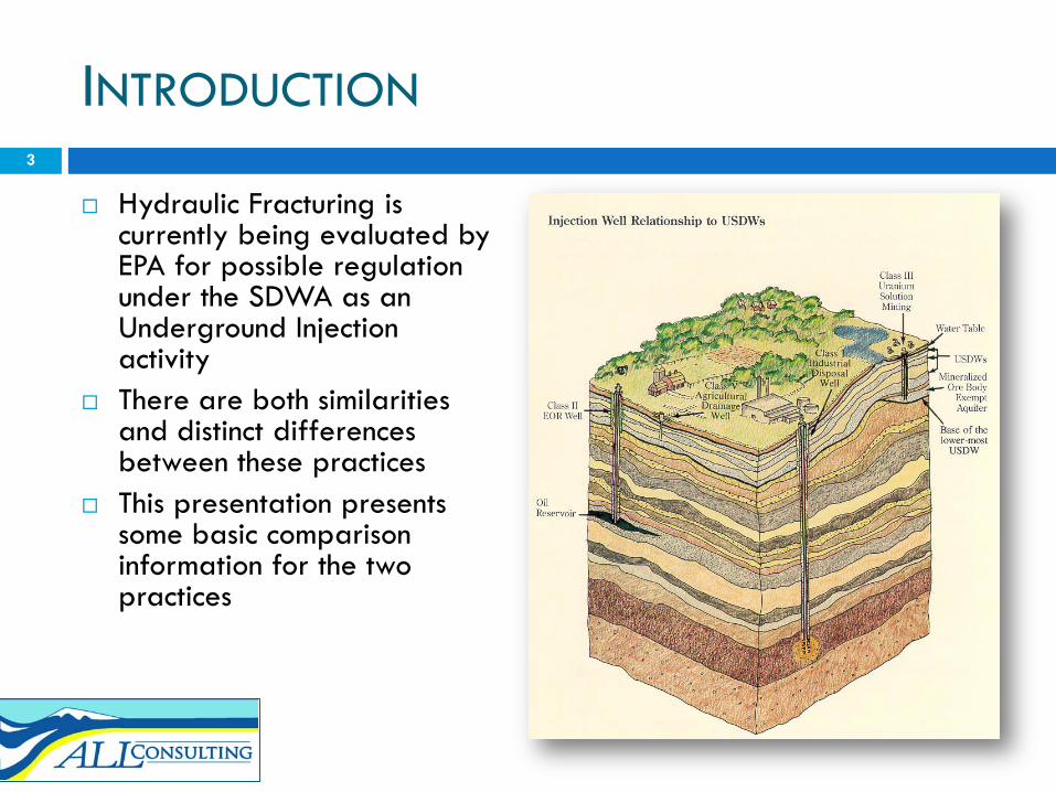
Hydraulic Fracturing is currently being evaluated by EPA for possible regulation under the SDWA as an Underground Injection activity
There are both similarities and distinct differences between these practices
This presentation presents some basic comparison information for the two practices
3
DESCRIPTION
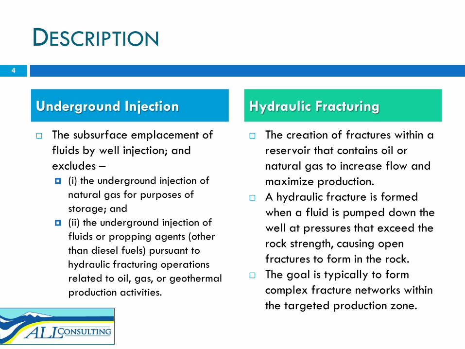
The subsurface emplacement of fluids by well injection; and excludes – (i) the underground injection of
natural gas for purposes of storage; and
(ii) the underground injection of fluids or propping agents (other than diesel fuels) pursuant to hydraulic fracturing operations related to oil, gas, or geothermal production activities.
The creation of fractures within a reservoir that contains oil or natural gas to increase flow and maximize production.
A hydraulic fracture is formed when a fluid is pumped down the well at pressures that exceed the rock strength, causing open fractures to form in the rock.
The goal is typically to form complex fracture networks within the targeted production zone.
4
Underground Injection Hydraulic Fracturing
REGULATORY PROGRAMS
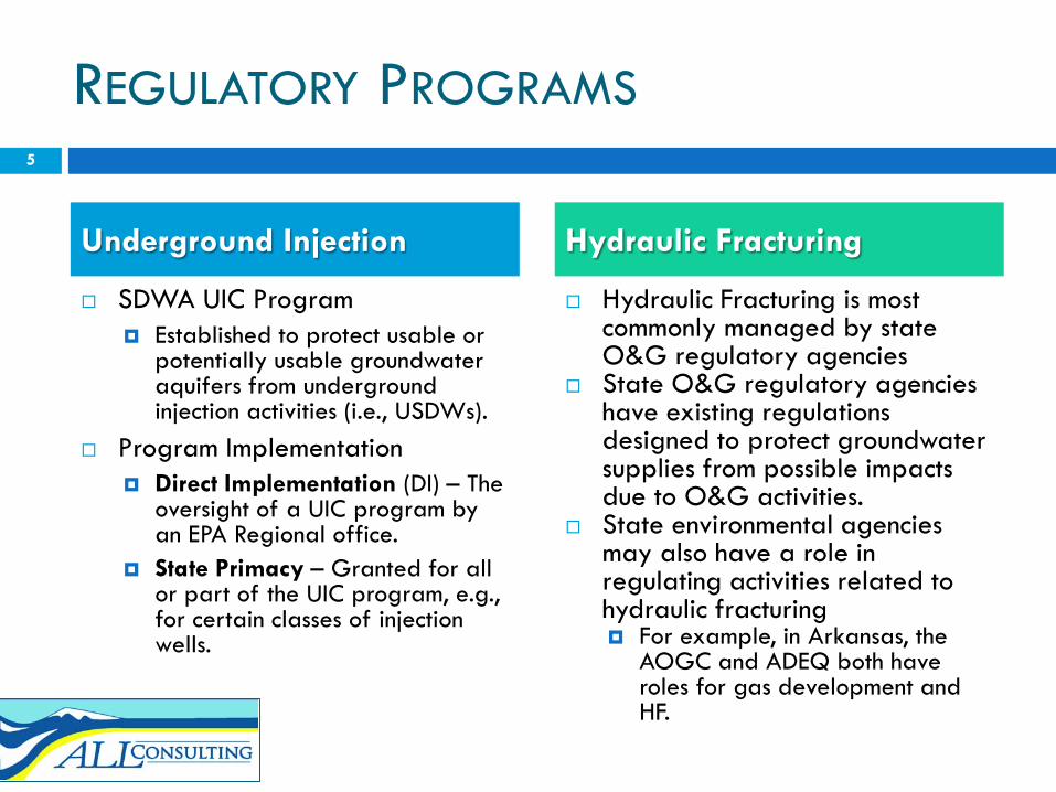
SDWA UIC Program Established to protect usable or
potentially usable groundwater aquifers from underground injection activities (i.e., USDWs).
Program Implementation Direct Implementation (DI) – The
oversight of a UIC program by an EPA Regional office.
State Primacy – Granted for all or part of the UIC program, e.g., for certain classes of injection wells.
Hydraulic Fracturing is most commonly managed by state O&G regulatory agencies
State O&G regulatory agencies have existing regulations designed to protect groundwater supplies from possible impacts due to O&G activities.
State environmental agencies may also have a role in regulating activities related to hydraulic fracturing For example, in Arkansas, the
AOGC and ADEQ both have roles for gas development and HF.
5
Underground Injection Hydraulic Fracturing
UIC PROGRAM REGULATORS
6
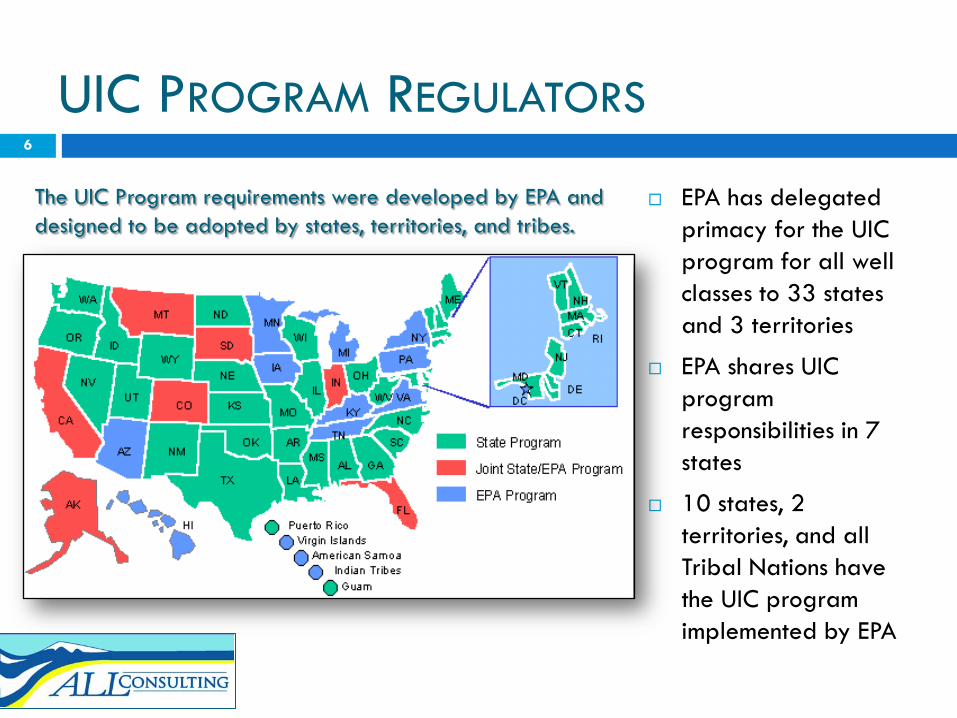
EPA has delegated primacy for the UIC program for all well classes to 33 states and 3 territories
EPA shares UIC program responsibilities in 7 states
10 states, 2 territories, and all Tribal Nations have the UIC program implemented by EPA
The UIC Program requirements were developed by EPA and designed to be adopted by states, territories, and tribes.
6
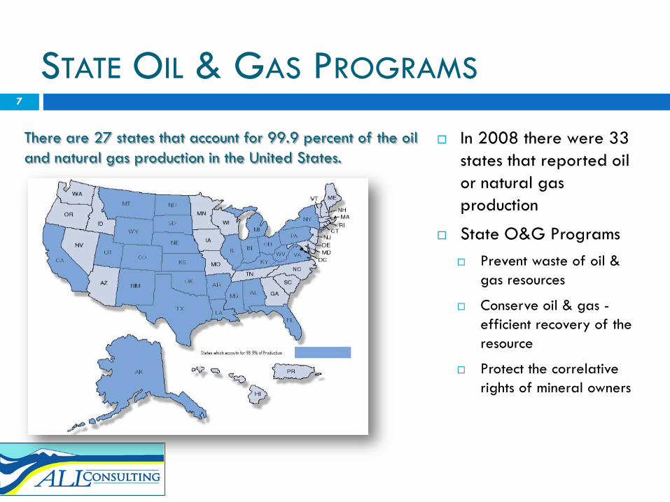
STATE OIL & GAS PROGRAMS
7
In 2008 there were 33 states that reported oil or natural gas production
State O&G Programs Prevent waste of oil &
gas resources
Conserve oil & gas -efficient recovery of the resource
Protect the correlative rights of mineral owners
There are 27 states that account for 99.9 percent of the oil and natural gas production in the United States.
7

PROGRAM PROTECTION TARGETS
Defined by Regulation, Underground Source of Drinking Water (USDW) – An aquifer that supplies or
contains a sufficient quantity of ground water to supply a public water system
fewer than 10,000 mg/l total dissolved solids
Not an exempted aquifer
Hydraulic fracturing is managed within state oil & gas programs
It is generally common that states have statute(s) relative to providing a clean and healthful environment within the state
Protection of water resources (groundwater and surface water) is a priority within every state and a priority of every oil & gas regulatory program
8
Underground Injection Hydraulic Fracturing
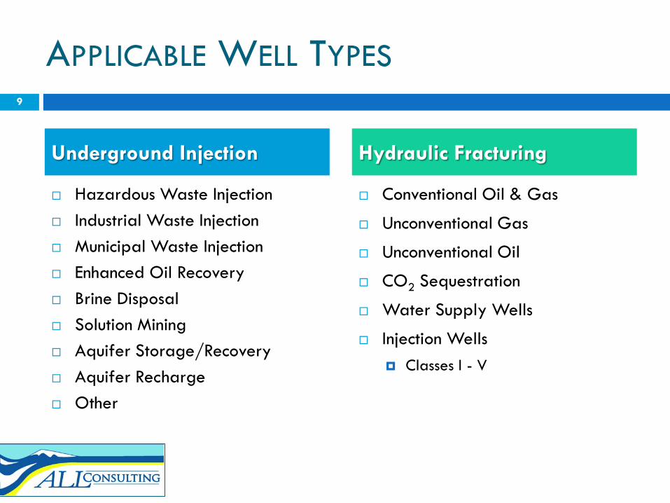
APPLICABLE WELL TYPES
Hazardous Waste Injection Industrial Waste Injection Municipal Waste Injection Enhanced Oil Recovery Brine Disposal Solution Mining Aquifer Storage/Recovery Aquifer Recharge Other
Conventional Oil & Gas
Unconventional Gas
Unconventional Oil
CO2 Sequestration
Water Supply Wells
Injection Wells Classes I - V
9
Underground Injection Hydraulic Fracturing

CLASS II INJECTION WELLS
Inject fluids associated with oil and natural gas production. Most of the injected fluid is salt water (brine), which is brought to the surface in the process of producing (extracting) oil and gas.
Inject Beneath the lowermost USDW. EPA Inventory lists 143,951 Class II wells in
operation in the United States, injecting over 2 billion gallons of brine every day.
Most oil and gas injection wells are in Texas, California, Oklahoma, and Kansas.
10
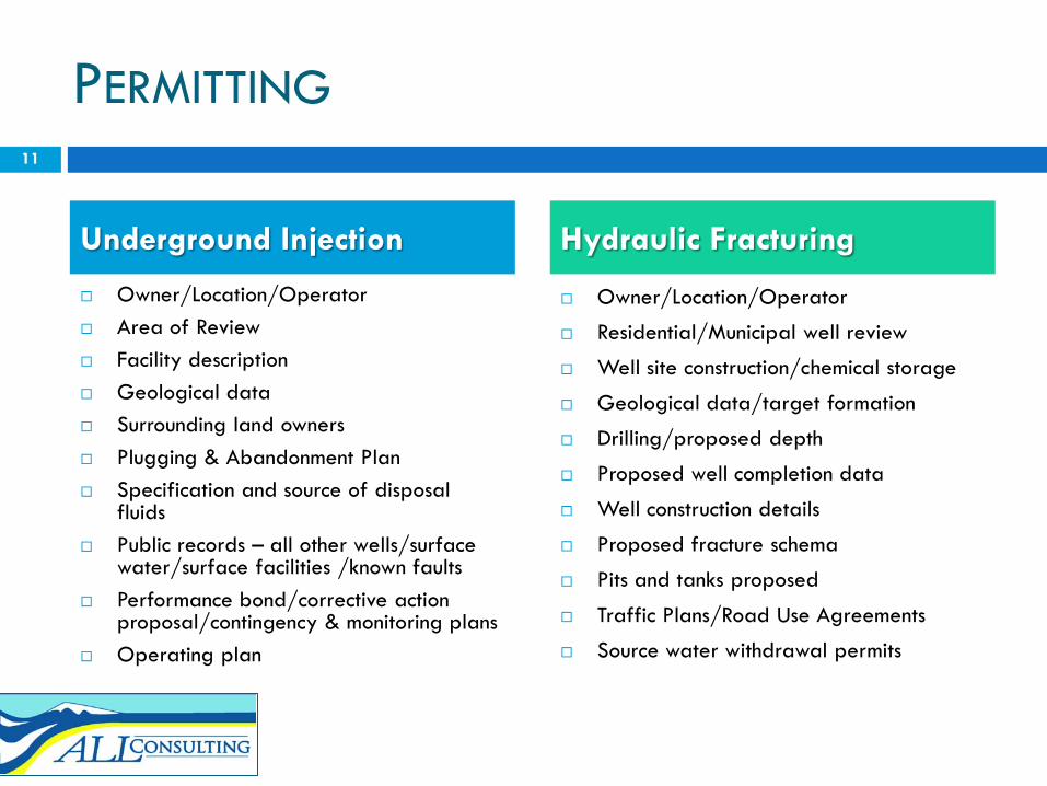
PERMITTING
Owner/Location/Operator Area of Review Facility description Geological data Surrounding land owners Plugging & Abandonment Plan Specification and source of disposal
fluids Public records – all other wells/surface
water/surface facilities /known faults Performance bond/corrective action
proposal/contingency & monitoring plans Operating plan
Owner/Location/Operator
Residential/Municipal well review
Well site construction/chemical storage
Geological data/target formation
Drilling/proposed depth
Proposed well completion data
Well construction details
Proposed fracture schema
Pits and tanks proposed
Traffic Plans/Road Use Agreements
Source water withdrawal permits
11
Underground Injection Hydraulic Fracturing

AREA CONSIDERATIONS
Area of Review Analysis ZOEI Presence of artificial penetration Springs Water wells Wells penetrating the injection
zone
USDW identification Confining interval Geological considerations
Pre-Site Assessment Geological considerations
Potential interfering wells
Area water supply wells
Surface and topographical challenges
Water sourcing
Other active production
Abandoned wells
12
Underground Injection Hydraulic Fracturing

CASING AND CEMENTING
Surface casing set below lowermost USDW and cemented to surface (generally)
Well casing and cementing program must prevent fluid movement into or between USDWs
Injectate confined to permitted injection interval
Surface casing setting depth typically established by state for purposes of protecting usable quality groundwater from oil and/or gas development activities
Some states include well casing and cementing programs in permits
13
Underground Injection Hydraulic Fracturing
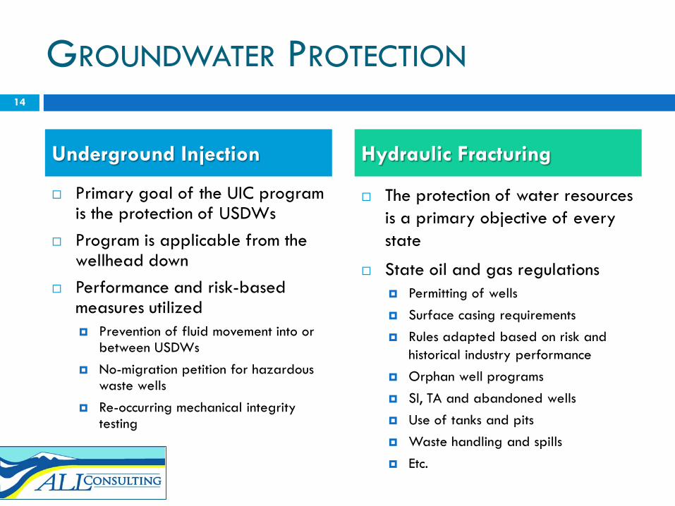
GROUNDWATER PROTECTION
Primary goal of the UIC program is the protection of USDWs
Program is applicable from the wellhead down
Performance and risk-based measures utilized Prevention of fluid movement into or
between USDWs No-migration petition for hazardous
waste wells Re-occurring mechanical integrity
testing
The protection of water resources is a primary objective of every state
State oil and gas regulations Permitting of wells Surface casing requirements Rules adapted based on risk and
historical industry performance Orphan well programs SI, TA and abandoned wells Use of tanks and pits Waste handling and spills Etc.
14
Underground Injection Hydraulic Fracturing

WELL INTEGRITY
Most injection wells must demonstrate internal and external mechanical integrity
For Class II wells, typical internal integrity tests are required once every 5 years
Some injection wells may be required to have continuous monitoring equipment to assure integrity is maintained
Operators commonly test wells before perforating to assure the well’s integrity is ready for fracturing activities
Surface equipment and piping is routinely tested
Testing may not be required, but is done as a best practice
Continuous monitoring is employed during fracturing
15
Underground Injection Hydraulic Fracturing

PRESSURE MANAGEMENT
Injection permits are generally granted with a maximum allowable injection pressure
It is common for wells to have a PMax determined by the fracture gradient of the top of the injection zone
Pressures exceeding the injection zone fracture gradient are allowed by rule
Wells may inject up to the PMaxthroughout the life of the well
Surface pressures sufficient to overcome friction and initiate fractures in the production zone are utilized
High friction factors are common due to facture fluid make-up (e.g., slurry)
Pressures maintained below pressure ratings of well tubulars and surface equipment (e.g., wellhead)
Pressures are maintain for duration of fracturing job (e.g., a few hours per stage)
16
Underground Injection Hydraulic Fracturing
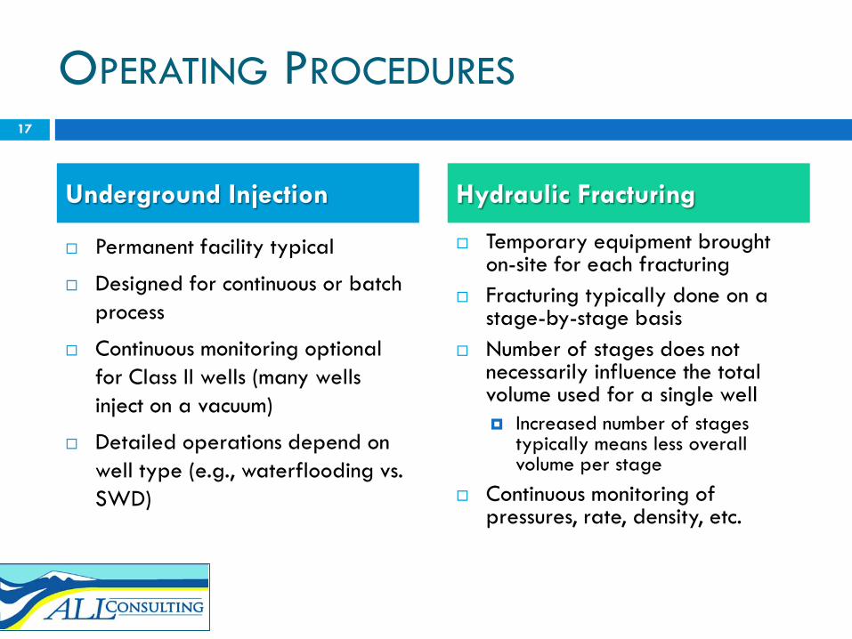
OPERATING PROCEDURES
Permanent facility typical
Designed for continuous or batch process
Continuous monitoring optional for Class II wells (many wells inject on a vacuum)
Detailed operations depend on well type (e.g., waterflooding vs. SWD)
Temporary equipment brought on-site for each fracturing
Fracturing typically done on a stage-by-stage basis
Number of stages does not necessarily influence the total volume used for a single well Increased number of stages
typically means less overall volume per stage
Continuous monitoring of pressures, rate, density, etc.
17
Underground Injection Hydraulic Fracturing

EXAMPLE FACILITIES/EQUIPMENT
Underground Injection Hydraulic Fracturing
18
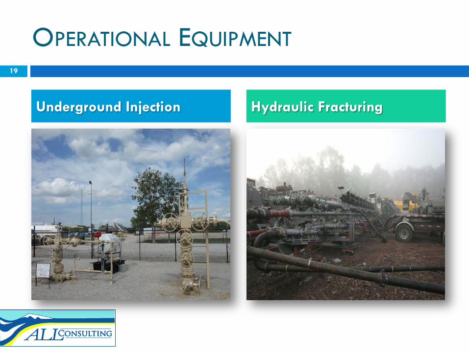
OPERATIONAL EQUIPMENT
Underground Injection Hydraulic Fracturing
19
FLUIDS DISPOSITION
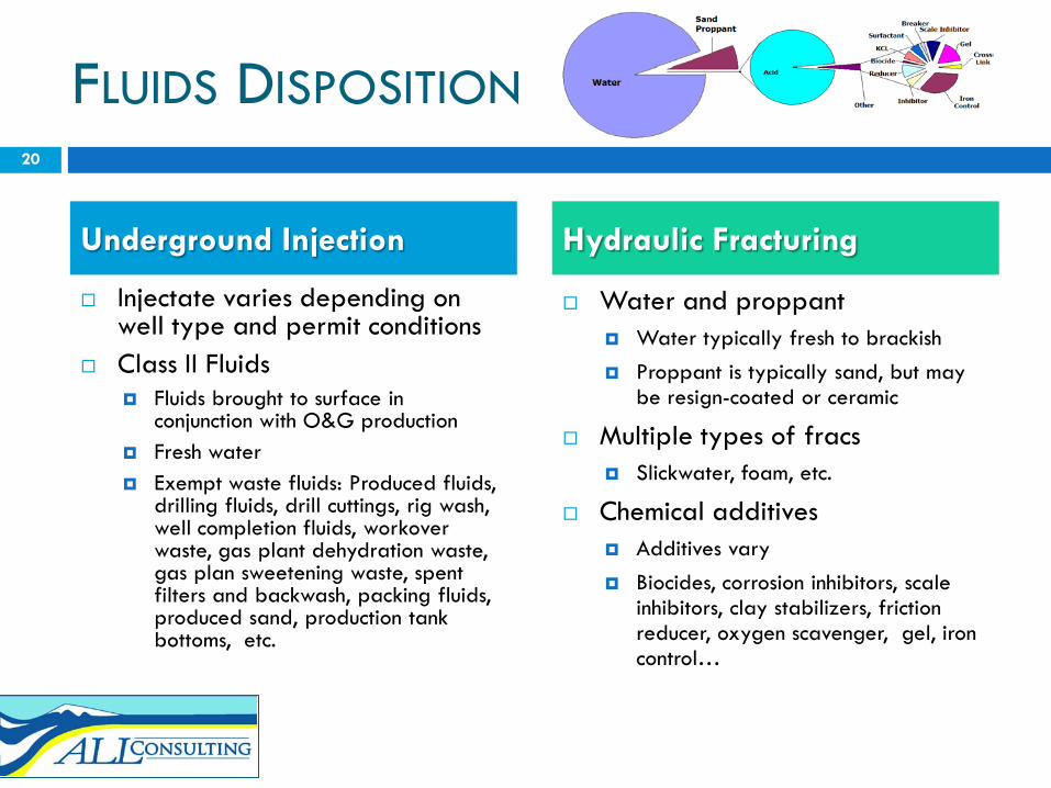
Injectate varies depending on well type and permit conditions
Class II Fluids Fluids brought to surface in
conjunction with O&G production Fresh water Exempt waste fluids: Produced fluids,
drilling fluids, drill cuttings, rig wash, well completion fluids, workover waste, gas plant dehydration waste, gas plan sweetening waste, spent filters and backwash, packing fluids, produced sand, production tank bottoms, etc.
Water and proppant Water typically fresh to brackish Proppant is typically sand, but may
be resign-coated or ceramic
Multiple types of fracs Slickwater, foam, etc.
Chemical additives Additives vary Biocides, corrosion inhibitors, scale
inhibitors, clay stabilizers, friction reducer, oxygen scavenger, gel, iron control…
20
Underground Injection Hydraulic Fracturing

FLUID CHARACTERIZATION
Injection characterization is part of the permitting process
The extent of characterization is generally dependant on the well class and fluid proposed for injection
The UIC program allows for some characterization details to be maintained as confidential information
Primary fluids are disclosed as part of the completion report
MSD Sheets are made available upon request
Historically, the make-up of some products are maintained as proprietary and have not been reported
Recently, multiple states are modifying rules to require full disclosure of fracturing additives
21
Underground Injection Hydraulic Fracturing

VOLUME VARIATIONS
Injection rates/volumes depend on well, formation, and operational objectives
Common for wells to inject 1,000 to over 20,000 barrels of fluid per day
Injection and disposal wells may or may not be continuous, but typically operate year-round for multiple years
Not uncommon for wells to be used for injection for 20+ years
Fluid volumes depend on the type of HF technique utilized
HV slickwater fracturing on horizontal wells commonly use 2-5 million gallons of water per well over 10 – 20 stages
The number of stages is dependant upon the interval to be fractured (a vertical well may use only one stage), thickness of the target zone, lithology of the formation, and other factors
22
Underground Injection Hydraulic Fracturing

REPORTING
Reporting varies depending on well type
For Class II wells, annual reporting of monthly average and maximum rate and pressure data is most common
Depending on permit conditions/requirements, water source information or water analysis may also be required
Summation of hydraulic fracturing activities have historically be reported on the well completion report
Some states require service tickets (e.g., Arkansas)
Several states have been modifying reporting rules, including requiring summary details by fracturing stage
23
Underground Injection Hydraulic Fracturing

FINANCIAL RESPONSIBILITY
Financial responsibility is a requirement of the UIC program
Financial responsibility is typically tied to plugging costs of the well
A plugging plan and cost estimate may be required for permitting
Blanket bonds are acceptable Some individual well bonds
States require bonding for O&G producing wells
Bonding requirements vary by state, but are generally tied to plugging liability
State agencies have a variety of tools relative to enforcement should problems arise
24
Underground Injection Hydraulic Fracturing

RISK PROBABILITY
Per a 1989 API and DOE study for basins with “reasonable” likelihood of corrosion, risk probability of injectate reaching a USDW ranged from one in 200,000 to one in 200 million for wells injecting on a continuous basis
Many states implement the Risk Based Data Management System and are able to assess risk probability on an ongoing basis
HF events for most well types (including shale gas wells) occur through multiple installed concentric casings over a short duration with considerable vertical separation (thousands of feet) of confining type zones between the production zone and the lowermost USDWs
Using the same technique as implemented for the 1989 API/DOE study, risks of fracturing fluids reaching a USDW would generally be far less probable than for injection wells
Underground Injection Hydraulic Fracturing
25
SUMMARY
Underground injection and hydraulic fracturing have some distinct similarities Pumping fluid into deep underground formations
Surface casing protective of fresh water
Confidentiality of some injectate/fracturing fluids
Underground injection and hydraulic fracturing have some distinct differences Long-term injection versus short-term pumping
Concern of corrosion of tubulars over time due to corrosive injectate
Fracturing is short-term followed by production opposed to long-term injection
Fracturing is not limited to unconventional gas wells, but is also done on injection wells, water wells, and other types of wells for a variety of purposes
DOE/API study found risks of injection fluids reaching a USDW to be remote. Based on operation, similar risks for fracturing would be less.
26
J. Daniel Arthur1718 S. Cheyenne Avenue
Tulsa, Oklahoma [email protected]
CONTACT AND CITING INFORMATION
Arthur, J.D., “A Comparative Analysis of Hydraulic Fracturing and Underground Injection”, Presented at the GWPC Water/EnergySymposium, Pittsburgh, Pennsylvania, September 25-29, 2010.
27