a comparative analysis on the effect of double- skin...
TRANSCRIPT

A Comparative Analysis On The Effect Of Double-
Skin Façade Typologies On Overall Building Energy
Consumption Performance In A Temperate Climate
DT175a – Module: ARCH4258 – Final Year Dissertation
Aaron Regazzoli
C09424237
Supervisor: Rory Greenan
10/05/2013

Abstract
Bsc Architectural Technology i
Abstract
One of the most important factors affecting the energy performance within a building
is a carefully and efficiently designed façade. The primary aim of this research was
to present a critical examination of the effect on the energy consumption of an office
building located within a temperate climate utilising Double-Skin Façade construction
as opposed to a conventional single-skin curtain wall system.
A comparative analysis of the effect on the overall energy consumption within an
office building was investigated in which a combination of various Double-Skin
Façade configurations, systems and cavity depths were utilised.
The use of computer aided dynamic thermal modelling was incorporated in order to
ensure the calculation of accurate and efficient simulations of the various Double-
Skin Façade systems due to the complex nature of the various functions within the
façade cavity.
Through the use of the dynamic thermal modelling simulations, a detailed analysis of
the efficiency of each respective combination of Double-Skin Façade construction
simulated was comprised. As such the optimum façade combination for use within
an office building located in a temperate climate was identified.

Acknowledgements
Bsc Architectural Technology ii
Acknowledgements
I would like to express my sincere thanks and appreciation to all staff of Dublin
Institute of Technology throughout my time within the college.
In particular to my current year head Sima Rouholamin for always finding the time
when I was in need of any assistance or guidance.
My assistant year head David Palmer, this dissertation wouldn’t have been possible
without his continuous guidance and direction. I truly appreciate his interest and
association with this research.
My research supervisor Rory Greenan, who provided me with valuable knowledge
and input throughout the course of the dissertation. In particular for getting me
started with the complex simulations and patiently replying to any queries which I
had.
Finally, I am indebted to my family, girlfriend and friends for encouraging me to
pursue this degree and research, without their support and encouragement
throughout my time within the course this would not have been possible.
Aaron Regazzoli,
May 2013.

Declaration
Bsc Architectural Technology iii
Declaration
I hereby declare that the work described within this dissertation is, except where
otherwise stated, entirely my own work and has not been submitted as an exercise
for a degree at this or any other university.
___________________
Aaron Regazzoli,
10/05/2013.

Contents
Bsc Architectural Technology iv
Table of Contents
Abstract ....................................................................................................................... i
Acknowledgements ..................................................................................................... ii
Declaration ................................................................................................................. iii
1.0 Introduction .......................................................................................................... 1
1.2 Double-Skin Façade Concept ........................................................................... 2
1.3 Research Objectives ......................................................................................... 4
2.0 Double Skin Façade Configuration ....................................................................... 6
2.1 Double-Skin Façade Construction .................................................................... 6
2.2 Double-Skin Façade Configuration ................................................................... 7
2.2.3 Box Façade ................................................................................................ 8
2.2.4 Corridor Façade ......................................................................................... 9
2.2.5 Shaft-Box Façade .................................................................................... 10
2.2.6 Multi-Storey Façade ................................................................................. 11
2.3 Double-Skin Façade System .......................................................................... 12
2.3.1 Naturally Ventilated Cavity ....................................................................... 12
2.3.2 Sealed Cavity ........................................................................................... 12
2.3.3 Regulating Cavity (Mixed-Mode Ventilation) ............................................ 13
3.0 The Role of Double-Skin Façades – Energy Consumption ................................ 14
3.1 Energy Performance - Double-Skin Façade ................................................... 15
3.2 Thermal Buoyancy (Stack Effect) ................................................................... 16
4.0 Dynamic Thermal Modelling - Methodology ....................................................... 18
4.1 Research Context ........................................................................................... 18
4.2 Establishing Base Model Parameters ............................................................. 19
4.2.1 Hawkins House Redevelopment – ‘’Drum’’ Office Area .......................... 19
4.2.2 Conventional Single-Skin Façade – Base Model Analysis ....................... 22
4.2.3 Double-Skin Façade Configurations ......................................................... 23

Contents
Bsc Architectural Technology v
4.3 Analysis / Simulations ..................................................................................... 24
4.3.1 SunCast ................................................................................................... 24
4.3.3 Vista Results Analysis .............................................................................. 25
4.3.4 MacroFlo .................................................................................................. 26
5.0 Dynamic Thermal Modelling Simulations ........................................................... 27
5.1 Analysis of Simulation Results ........................................................................ 27
5.1.1 Annual Energy Consumption (mWh) ........................................................ 27
5.1.2 Annual Heating and Cooling Loads (kWh) ............................................... 28
5.1.3 Annual Energy Consumption (kWh/m²) .................................................... 30
6.0 Conclusions and Recommendations .................................................................. 34
6.1 Comparison of Façade Configuration Energy Consumption ........................... 34
6.2 Recommendations – Optimum Cavity Depth .................................................. 37
6.3 Areas for Further Research ............................................................................ 38
References ............................................................................................................... 39
Appendix 1: The History of Double-Skin Façades ...................................................... 1
Appendix 2: IES Virtual Environment User Interface .................................................. 1
Appendix 3: Double-Skin Façade – Energy Consumption and Cost Analysis ............ 1

Table of Figures
Bsc Architectural Technology vi
Table of Figures
Chapter 1
Figure 1.1: Impact of the building façade on energy consumption (King, 2010). ........ 2
Figure 1.2: Typical Double-Skin Façade Configuration (ArchiExpo, 2003) . ............... 3
Chapter 2
Figure 2. 1: Typical Double-Skin Façade Composition (Caine, 2013). ....................... 6
Figure 2. 2: Corridor Façade Google SketchUp Model............................................... 7
Figure 2. 3: Box Façade Google SketchUp Model ..................................................... 7
Figure 2. 4: Multi-Storey Façade Google SketchUp Model ........................................ 7
Figure 2. 5: Shaft-Box Façade Google SketchUp Model ............................................ 7
Figure 2. 6: Box Façade Elevation ............................................................................. 8
Figure 2. 7: Box Façade Section ................................................................................ 8
Figure 2. 8: Box Façade Plan ..................................................................................... 8
Figure 2. 9: Site Assembley of Prefabricated Box Façade Elements (Oesterle, et al.,
2001). ......................................................................................................................... 8
Figure 2. 10: Corridor Façade Section ....................................................................... 9
Figure 2. 11: Corridor Façade Elevation ..................................................................... 9
Figure 2. 12: Corridor Façade Plan ............................................................................ 9
Figure 2. 13: Corridor Façade (Oesterle, Lieb, Lutz, & Heusler, 2001). ..................... 9
Figure 2. 14: Shaft-Box Façade Elevation ................................................................ 10
Figure 2. 15: Shaft-Box Façade Section ................................................................... 10
Figure 2. 16: Shaft-Box Façade Plan ....................................................................... 10
Figure 2. 17: ARAG 2000 Building Shaft-Box Façade (Oesterle, et al., 2001). ........ 10
Figure 2. 18: Multi-Storey Façade Plan .................................................................... 11
Figure 2. 19: Multi-Storey Façade Elevation ............................................................ 11
Figure 2. 20: Multi-Storey Façade Section ............................................................... 11
Figure 2. 21: Multi-Storey Façade (Gonchar, 2013). ................................................ 11
Figure 2. 22: Classification of Double-Skin Façades and Ventilation Methods. ........ 12
Figure 2. 23: Sketch Indicating airflow induced due to the stack effect. ................... 12
Figure 2. 24: Motorised Façade Ventilation Opening (BBRI, 2004). ......................... 13

Table of Figures
Bsc Architectural Technology vii
Chapter 3
Figure 3. 1: Schematic diagram heat transfer through a Double-Skin Façade. ........ 15
Figure 3. 2: Double-Skin Façade Winter and Summer Operations (Gonchar, 2013).
................................................................................................................................. 17
Chapter 4
Figure 4. 1: Proposed Redevelopment of Hawkins House South-Façade................ 18
Figure 4. 2: Hawkins House Redevelopment which highlights the proposed office
area. ......................................................................................................................... 19
Figure 4. 3: IES Applications User Interface. ............................................................ 20
Figure 4. 4: IES Room Function Interface. The office area (in green) and additional
Hawkins House redevelopment (pink) is highlighted above. .................................... 21
Figure 4. 5: IES Room Template Interface. .............................................................. 21
Figure 4. 6: Hawkins House Redevelopment 3D IES Virtual Environment Model. ... 22
Figure 4. 7: Hawkins House Redevelopment IES 3D Base Model. .......................... 22
Figure 4. 8: Corridor Façade .................................................................................... 23
Figure 4. 9: Multi-Storey Façade .............................................................................. 23
Figure 4. 10: Shaft-Box Façade ............................................................................... 23
Figure 4. 11: Box Façade ......................................................................................... 23
Figure 4. 12: IES SunCast – Solar Shading Calculations. ........................................ 24
Figure 4. 13: ApacheSim Parameters User Interface. .............................................. 25
Figure 4. 14: Vista Results Analysis Interface. ......................................................... 25
Figure 4. 15: MacroFlo Openings Database Manager Interface. .............................. 26
Chapter 5
Figure 5. 1: Annual Energy Consumption – Dynamic Thermal Modelling Simulations.
................................................................................................................................. 27
Figure 5. 2: Annual Heating and Cooling Loads - 200mm Cavity Depth. ................. 28
Figure 5. 3: Annual Heating and Cooling Loads - 600mm Cavity Depth. ................. 29
Figure 5. 4: Annual Heating and Cooling Loads - 1000mm Cavity Depth. ............... 29
Figure 5. 5: Box Façade – Annual Energy Consumption (kWh/m²). ......................... 31
Figure 5. 6: Corridor Façade – Annual Energy Consumption (kWh/m²). .................. 31
Figure 5. 7: Shaft-Box Façade – Annual Energy Consumption (kWh/m²). ............... 32
Figure 5. 8: Multi-Storey Façade – Annual Energy Consumption (kWh/m²). ............ 32
Figure 5. 9: Shaft-Box Façade Configuration – Airflow Concept. ............................. 33

Table of Figures
Bsc Architectural Technology
viii
Chapter 6
Figure 6. 1: Annual Energy Consumption – Facade Efficiency Comparison. ........... 34
Figure 6. 2: Multi-Storey Façade Regulating Cavity – Determination of Optimal
Cavity Depth. ............................................................................................................ 35
Figure 6. 3: Annual Energy Consumption Cost – Optimal Cavity Depth. .................. 36
Figure 6. 4: Horizontal Pivoting Transparent Slats (Teuxido, 2013). ........................ 38
Appendix 1
Appendix 1. 1: Steiff Factory Giengen, Germany. Circa 1904 (Solla, 2013). .............. 1
Appendix 1. 2: Famhouse Box-Type Windows in Mürren, Switzerland (Oesterle, et
al., 2001). ................................................................................................................... 1
Appendix 1. 3: Narkomfin Housing Building, Moscow, Russia. Circa 1928 (Wolfe,
2013). ......................................................................................................................... 2
Appendix 1. 4: Corbusier Sketch Illustrating Ideas (Tascón & Hernandez., 2008). .... 2
Appendix 2
Appendix 2. 1: Office Room Conditions. ..................................................................... 1
Appendix 2. 2: Double-Skin Façade Room Conditions. .............................................. 1
Appendix 2. 3: Double-Skin Façade MacroFlo Opening Template – Sealed Cavity. .. 2
Appendix 2. 4: Double-Skin Façade MacroFlo Opening Template – Naturally
ventilated Cavity. ........................................................................................................ 2
Appendix 2. 5: Double-Skin Façade MacroFlo Opening Template – Regulating
Cavity. ........................................................................................................................ 3
Appendix 3
Appendix 3. 1: Annual Energy Consumption Overview (mWh). ................................. 1

Table of Tables
Bsc Architectural Technology ix
Table of Tables
Chapter 1
Table 1.1: Reasearch Objectives Mapped to Methods...............................................5
Appendix 3
Appendix Table 3.1: Base Model Experimental Parameters.....................................1
Appendix Table 3.2: Base Model Examination..........................................................1
Appendix Table 3.3: IES Test Results.......................................................................2
Appendix Table 3.4: IES Test Results.......................................................................2
Appendix Table 3.5: IES Test Results.......................................................................2
Appendix Table 3.6: IES Test Results.......................................................................3
Appendix Table 3.7: IES Test Results.......................................................................3
Appendix Table 3.8: IES Test Results.......................................................................3
Appendix Table 3.9: IES Test Results.......................................................................4
Appendix Table 3.10: IES Test Results.....................................................................4
Appendix Table 3.11: IES Test Results.....................................................................4
Appendix Table 3.12: IES Test Results.....................................................................5
Appendix Table 3.13: IES Test Results ....................................................................5
Appendix Table 3.14: IES Test Results.....................................................................5

Chapter 1 Introduction
BSc Architectural Technology 1
1.0 Introduction
The primary aim of this research is to present a critical examination of the energy
performance associated with the use of various Double-Skin Façade typologies and
systems in an office building located within a temperate climate.
The concept of Double-Skin Façade construction is not a recent methodology and
dates back to the middle of the 19th century. However, rapid development of the
concept began during the 1970’s as a result of the oil crisis’ of 1973 and 1979
(Dickson, 2003). A growing concern regarding energy consumption during this period
resulted in an acceleration in improvements within the glass industry, and in turn
Double-Skin Façade technology also seen significant advancements (Bayram,
2003). A detailed account of the history of Double-Skin Façades can be seen in
Appendix 1.
Currently within the construction industry, buildings are not merely a simple
combination of stone and glass. In fact according to (Bayram, 2003) they are
becoming increasingly more energy efficient and as a result are achieving high
performance standards due to constant technological advancements and ever
increasing performance requirements.
The building façade acts as a ‘’filter’’ between the internal and external
environments. As a result It provides protection to the building interior from
undesirable impacts such as excessive heat gain, cold, radiation and wind generated
from the external environment (Consultants, 2013). As a result the façade is the
primary moderator between the external and internal environments, which underlines
the importance of the façade as a key aspect of reducing overall energy
consumption (Palmer, 2011). According to (King, 2010) 8% of energy consumption
within office buildings is as an direct result of heat loss through the façade walls and
windows; however the façade can have an indirect effect on a further 56% of energy
consumed through related functions such as infiltration, HVAC – heating, cooling and
air-conditioning and lighting (Palmer, 2011), see figure 1.1 below for a diagrammatic
representation of the effects in which the building façade impacts on overall energy
consumption.

Chapter 1 Introduction
BSc Architectural Technology 2
The possibility of Double-Skin Façade construction providing a reduction in energy
consumption related to heating and cooling loads in an office building is studied to
determine whether it is an energy efficient method of façade construction. In addition
a brief cost analysis will be outlined to evaluate if reduced energy consumption
justifies the initial construction costs in a long-term assessment. Previous cost
analysis show that the initial cost of Double-Skin Façade construction can range
from 200%-300% of conventional single-skin façade construction, depending on the
façade composition (Bayram, 2003).
1.2 Double-Skin Façade Concept
The term Double-Skin Façade can be defined as a combination of a traditional
single-skin façade which is doubled on the outside by a second layer, essentially an
additional glazed façade. Each of these layers are commonly referred to as a skin,
hence the origin of the widely used term ‘’Double-Skin Façade’’. In addition, a
naturally ventilated, sealed or self-regulating cavity is located between each skin
having a width which can range from several centimetres at the narrowest to several
metres for the widest accessible cavities (BBRI, 2004).
Figure 1. 1: Impact of the building façade on energy consumption (King, 2010).

Chapter 1 Introduction
BSc Architectural Technology 3
The glazing may stretch over an entire structure or over just a portion of it. The
internal layer of glass, typically insulating, serves as part of a conventional structural
wall or a curtain wall, while the additional layer, usually single glazed, is placed in
front of the main glazing and as a result creates the air space (Uuttu, 2001). An
example of typical Double-Skin Facade configuration is shown below in figure 1.2:
According to (Arons, 2000) the main objectives of the Double-Skin Façade concept
can be briefly defined under the following headings:
1. Reduced Energy Consumption and Ecological Responsibility
2. Natural Ventilation
3. Cost Reduction
4. Acoustic Insulation
5. Occupant Comfort
6. Increased Occupant Productivity
7. Additional Building Security
External Layer
Ventilation Grille
Internal Layer
Spandrel Panel
Grated Walkway
Figure 1. 2: Typical Double-Skin Façade Configuration (ArchiExpo, 2003) .

Chapter 1 Introduction
BSc Architectural Technology 4
1.3 Research Objectives
The Aim of this research is to provide a critical evaluation as to whether Double-Skin
Façade construction plays an important role in reducing energy consumption within
office buildings in a temperate climate.
The objectives of this research are as follows:
1. To characterise the various methods of Double-Skin Façade configuration and
construction used within the construction industry.
2. To research and establish the advantages and disadvantages associated with
the respective systems of Double-Skin Façade construction.
3. To determine the role and effect of Double-Skin Façade construction on
energy consumption and performance of buildings.
4. To carry out a comparative analysis of the effect on energy consumption on
buildings through various Double-Skin Façade configurations and systems as
opposed to conventional curtain wall construction.
5. To determine the performance efficiency against conventional curtain wall
construction and the associated payback durations of each respective system
in relation to the information obtained through research.
6. To establish the optimal combination of Double-Skin Facade configuration,
system and cavity depth in relation to overall building energy consumption for
use within an office building located in a temperate climate.
Objectives mapped to Research Methods:
Objectives Research Methods
Characterise the various methods of
Double-Skin Façade configurations.
Review current literature on methods of
classification of Double-Skin Façade typologies.
To research and establish the
advantages and disadvantages
associated with the respective systems
of Double-Skin Façade construction.
Review current literature on the advantages and
disadvantages that are associated which each
respective system of Double-Skin Façade
configuration with the construction industry.
To determine the role and effect of
Double-Skin Façade construction on
energy consumption and performance of
buildings.
Review available data and literature on the role
and effect that Double-Skin Façade construction
plays on the consumption of energy within
buildings.

Chapter 1 Introduction
BSc Architectural Technology 5
To carry out a comparative analysis of
the effect on energy consumption on
buildings through various Double-Skin
Façade configurations and systems as
opposed to conventional single-skin
curtain wall construction.
To perform computer aided dynamic thermal
modelling on various scenarios to determine the
respective energy consumption of various
Double-Skin Façade configurations.
To determine the performance efficiency
against conventional curtain wall
construction and the associated payback
durations of each respective system in
relation to the information obtained
through research.
Prepare a comparison of results from thermal
dynamic modelling to determine respective
system efficiency. Review of current data on
estimated Double-Skin Façade construction
costs and provide detailed outputs of payback
periods of each respective system tested.
To establish the optimal combination of
Double-Skin Façade configuration,
system and cavity depth in relation to
overall building energy consumption for
use within an office building located in a
temperate climate.
Through the comparison and analysis of the
results obtained through the use of the dynamic
thermal modelling simulations, to identify and
determine the most efficient combination of the
various double-skin façade parameters
evaluated.
Table 1.1: Reasearch Objectives Mapped to Methods.
In Conclusion, through a detailed investigation into the various methods of Double-
Skin Façade construction and configuration, the knowledge required in order to
effectively and efficiently determine the parameters of the dynamic thermal modelling
simulations are to be identified.

Chapter 2 Double-Skin Façade Configuration
BSc Architectural Technology 6
2.0 Double Skin Façade Configuration
In this chapter the typical composition of a Double-Skin Façade is examined in
further detail, together with an explanation of the various methods of classification
used within the construction industry to define the Double-Skin Façade configuration.
2.1 Double-Skin Façade Construction
There are a wide range of definitions from a large range of authors as to what
components actually constitute a Double-Skin Façade. However, the layers of a
Double-Skin Façade are generally comprised of the following elements:
External Glazing: The exterior layer
usually comprises of heat strengthened
safety or laminated safety glass. It may
be airtight or open with air inlet and
outlet openings controlled by either
manual or automated opening vents.
This layer may be completely glazed
and is used as a rain screen to provide
protection to the interior layer from the
external climatic conditions (Lee,
Selkowitz, Bazjanac, Inkarojrit, & Kohler,
2002).
Internal Glazing: The interior layer is
usually comprised of a fixed or operable
thermal insulating double or triple pane
glazed unit. Clear, low emmitance
coating, solar diffusion glazing, etc. can
be used on the internal glazing in order
to reduce the radiative heat gains to the
interior. This layer is generally
comprised of some built or opaque
elements and may contain fixed or operable casement or hopper windows,
depending on the ventilation strategy used (Lee, et al., 2002).
Figure 2. 1: Typical Double-Skin Façade Composition
(Caine, 2013).

Chapter 2 Double-Skin Façade Configuration
BSc Architectural Technology 7
Intermediate Cavity: The intermediate cavity between the external and internal
layers can be naturally, regulating (mixed-mode ventilation) or completely sealed.
The width of the cavity can vary as a function of the applied concept and can range
from 200mm to over 2m. The width of the intermediate cavity determines the
physical properties of the façade and the way in which it is maintained (Streicher et
al., 2007).
Any adjustable sun shading or day lighting equipment enhancement devices are
generally installed within the intermediate cavity to protect the internal rooms from
external elements and as a less expensive method than the use of externally
mounted systems. The airflow throughout the intermediate space is determined by
solar induced thermal buoyancy and through the effects of the wind (Oesterle, et al.,
2001).
2.2 Double-Skin Façade Configuration
There are many methods of configuration and classification of Double-Skin Façades.
Each one is dependent on design principles such as the origin and direction of air
flow within the cavity, the façade configuration and also according to the form in
which the intermediate space is divided. However, the principle factor which
determines the Double-Skin Façades classification is according to the desired
ventilation function (Oesterle, et al., 2001).
There are four main categories of configuration of Double-Skin Façades, as
mentioned below:
1. Box Façade: (Figure 2.2)
2. Corridor Façade (Figure 2.3)
3. Shaft-Box Façade (Figure 2.4)
4. Multi-Storey Façade (Figure 2.5)
Figure 2. 2: Box Façade
Google SketchUp Model
Figure 2. 3: Corridor
Façade Google SketchUp Model
Figure 2. 4: Shaft-Box
Façade Google SketchUp Model
Figure 2. 5: Multi-Storey
Façade Google SketchUp Model

Chapter 2 Double-Skin Façade Configuration
BSc Architectural Technology 8
2.2.3 Box Façade
According to (Oesterle, et al., 2001) the Box Façade is one of the oldest forms of
Double-Skin Façade configuration.
It is comprised of modular single storey Double-Skin Façade box units which are
divided by structural bay widths or on a room-by-room basis (Lee, et al., 2002).
The exterior single glazed skin contains openings in order to allow the ingress of
fresh air and the egress of stale air. Resulting in the ability of both the intermediate
space and internal rooms to be naturally ventilated (Oesterle, et al., 2001).
Box Façade configuration is most commonly used in situations where consideration
is given due to high external noise levels and when there are special requirements
regarding the transmittance of sound between adjoining rooms (Oesterle, et al.,
2001).
According to (Uuttu, 2001) the main advantages of a Box Façade configuration are:
1. Improvement of sound insulation both
horizontally and vertically across the façade
cavity.
2. Division into fire protection levels is achievable
throughout the façade cavity.
3. Occupant Controlled natural window ventilation
can be achieved.
Figure 2. 2: Box Façade Elevation Figure 2. 3: Box Façade Section Figure 2. 4: Box Façade Plan
Figure 2. 5: Site Assembley of
Prefabricated Box Façade Elements (Oesterle, et al., 2001).

Chapter 2 Double-Skin Façade Configuration
BSc Architectural Technology 9
2.2.4 Corridor Façade
A Corridor Façade is a single-storey façade which is separated horizontally at each
intermediate floor area (Uuttu, 2001).
It does not contain any vertical divisions except those that are required at the corner
of the building or elsewhere due to structural, acoustic or fire protection reasons
(Lee, et al., 2002).
The exterior single glazed skin contains openings that are usually positioned in a
staggered format from bay to bay in order to prevent stale air extracted on one floor
entering the cavity space of the floor immediately above (Oesterle, et al., 2001).
A Corridor Façade configuration is typically used in the situation of high-rise
buildings (Oesterle, et al., 2001).
According to (Uuttu, 2001) the main advantages of a Corridor Façade configuration
are:
1. Improvement of sound insulation both horizontally and
vertically across the façade cavity.
2. Division into fire protection levels is achievable
throughout the façade cavity.
3. Occupant Controlled natural window ventilation can be
achieved.
Figure 2. 7: Corridor Façade Elevation Figure 2. 6: Corridor Façade Section Figure 2. 8: Corridor Façade Plan
Figure 2. 9: Corridor Façade
(Oesterle, Lieb, Lutz, & Heusler, 2001).

Chapter 2 Double-Skin Façade Configuration
BSc Architectural Technology 10
2.2.5 Shaft-Box Façade
The Shaft-Box Façade is a unique variation of a Box Façade configuration with a
combination of both a Double-Skin Façade with a Multi-Storey Cavity and one with a
single-storey cavity (Uuttu, 2001).
It is comprised of an alternating layout of box façade units and vertical shaft
elements that are linked through airflow openings (Oesterle, et al., 2001).
As a result the vertical height of the shaft creates strong uplift forces due to the
increased stack effect and draws the air from the box façade elements up to the top
of the shaft where it is exhausted (Lee, et al., 2002).
Shaft-Box Façade configuration is typically used in low-rise buildings (Oesterle, et
al., 2001).
According to (Uuttu, 2001) the main advantages of a Shaft-Box Façade configuration
are:
1. Improvement of sound insulation both
horizontally and vertically across the
façade cavity.
2. Occupant Controlled natural window
ventilation can be achieved.
3. Provides additional building security.
Shaft Element
Figure 2. 11: Shaft-Box Façade Section Figure 2. 10: Shaft-Box Façade Elevation Figure 2. 12: Shaft-Box Façade Plan
Figure 2. 13: ARAG 2000 Building Shaft-Box
Façade (Oesterle, et al., 2001).

Chapter 2 Double-Skin Façade Configuration
BSc Architectural Technology 11
2.2.6 Multi-Storey Façade
In a Multi-Storey Façade the cavity is not separated horizontally or vertically by
divisions, it extends over the whole extent of the building envelope (Oesterle, et al.,
2001).
The principle behind a Multi-Storey Façade is dependent on air that accumulates at
the top of the cavity will heat up on a warm day and as a result will be exhausted
from the openings in the roof or external skin and in turn will result in cooler air being
drawn in from the base of the façade and replacing the exhausted air (Uuttu, 2001).
A Multi-Storey Façade configuration is most suited where external noise levels are
high and acoustic insulation is a key design requirement (Oesterle, et al., 2001).
According to (Uuttu, 2001) the main advantages of a Multi-Storey Façade
configuration are as follows:
1. Improvement of sound insulation both horizontally
and vertically across the façade cavity.
2. Occupant Controlled natural window ventilation
can be achieved.
3. Provides additional building security.
4. Shading devices placed within the cavity are
protected from the climatic elements as opposed
to externally mounted systems
Figure 2. 15: Multi-Storey Façade Elevation Figure 2. 16: Multi-Storey Façade Section
Figure 2. 14: Multi-Storey Façade Plan
Figure 2. 17: Multi-Storey Façade (Gonchar, 2013).

Chapter 2 Double-Skin Façade Configuration
BSc Architectural Technology 12
2.3 Double-Skin Façade System
In addition there are numerous combinations and design possibilities by varying the
partition configuration, ventilation system and airflow method (Aksamija).
2.3.1 Naturally Ventilated Cavity
The British Standard BS EN (12792., 2003) defines the process of natural ventilation
as dependent on pressure differentiation without the aid of air movement
components. The two driving forces that determine the effectiveness of natural
ventilation in Double-Skin Façades are the differences in pressure within the cavity
generated by thermal buoyancy, or the stack effect, and also by the effect of wind
velocity (BBRI, 2004).
The principle of the stack effect is dependent on
the theory that the warm air inside the cavity is less
dense than the cooler external air, and as a result
will be drawn out from openings located at the top
of the building envelope; as a result cooler denser
air will enter openings lower down. The process
will continue if the air entering the building is
continuously heated, typically by casual or solar
gains (Baker, 2013). The principle of the stack
effect is shown in figure 2.23 to the right.
2.3.2 Sealed Cavity
According to (Permasteelisa, 2013) a sealed cavity, or closed cavity façade, refers to
the method in a Double-Skin Façade construction whereby the cavities between the
internal and external layers are completely sealed. The concept of a Closed Cavity
Façade is simple and provides a number of benefits according to (Permasteelisa,
2013) such as:
Sealed Regulating
Cavity Airflow
Solar Radiation
Figure 2. 18: Classification of Double-Skin Façades and Ventilation Methods.
Figure 2. 19: Sketch Indicating airflow induced due to the stack effect.

Chapter 2 Double-Skin Façade Configuration
BSc Architectural Technology 13
A sealed Double-Skin Façade improves glazing transparency.
Greater energy and cost efficiency compared to naturally ventilated methods.
A sealed façade cavity is an energy saving method of façade construction.
2.3.3 Regulating Cavity (Mixed-Mode Ventilation)
As opposed to either solely naturally ventilated or sealed cavities, it is possible for
several ventilation methods to be utilised simultaneously within a Double-Skin
Façade configuration. In certain cases, the ventilation method can be regulated and
determined by motorised ventilation openings which react with environmental
parameters, such as cavity air temperature, etc. (BBRI, 2004).
Motorised ventilation openings, as presented
in figure 2.24, enable the possibility to vary
from one method of ventilation to another as a
function of their position (BBRI, 2004).
According to CIBSE Guide A (2005)
guidelines such as when the cavity air
temperature exceeds a mean temperature of
28° the motorised ventilation openings will be
activated in order to allow the dissipation of
heat from the façade cavity and as a result
prevent overheating within the façade cavity.
In conclusion, the various Double-Skin Façade configurations and systems
mentioned above, in addition with the variation of the cavity depth, are to be
examined to determine the overall effect on building energy consumption. The role in
which Double-Skin Façade construction affects building energy consumption is
explored within the next chapter in order to determine the main energy saving
principles associated with the use of the Double-Skin Façade concept.
Figure 2. 20: Motorised Façade Ventilation Opening (BBRI, 2004).

Chapter 3 The Role of Double-Skin Façades - Energy Consumption
BSc Architectural Technology 14
3.0 The Role of Double-Skin Façades – Energy Consumption
In this chapter the effect on façade performance in the context of Double-Skin
Façade construction is presented, together with an explanation of the various
performative concepts associated.
As briefly mentioned in Chapter 1, the use of Double-Skin Façade construction
provides various performance enhancing benefits to the building envelope.
According to (Arons, 2000) these benefits can be defined under the following
headings:
1. Reduced Energy Consumption and Ecological Responsibility: Reduced
energy consumption is achieved by minimising solar gain through the façade
and reducing cooling loads.
2. Cost Reduction: Double-Skin Façades are significantly more expensive to
construct than a conventional single-skin façade, however according to
(Saelens, 2002) their use reduces long-term costs due to reduced energy
consumption.
3. Natural Ventilation: Due to the protection of the external skin, natural
ventilation through the cavity can be achieved whilst not compromising
occupant comfort during harsh climatic conditions such as wind, rain and
snow.
4. Acoustic Insulation: Due to the addition of an external skin, it is possible to
achieve the same degree of acoustic insulation with the windows open as you
can with the windows closed in conventional single-skin façade construction.
5. Occupant Comfort/Productivity: As occupants are able to control light
penetration with louvers or shading devices and to regulate air movement and
temperature with operable windows the overall building comfort levels are
increased. In turn due to increased environmental control and comfort levels,
work productivity is increased.
6. Additional Security: Double-Skin Façades provide a relatively unobtrusive
method of achieving building security due to a continuous glazing layer with
small ventilation grilles as opposed to project openings with bars or vents.

Chapter 3 The Role of Double-Skin Façades - Energy Consumption
BSc Architectural Technology 15
3.1 Energy Performance - Double-Skin Façade
Energy consumption in relation to Double-Skin Façades for heating and cooling
loads is directly related with the total glazing area as the majority of the heat gains
and losses occur through the glass surfaces (Bayram, 2003).
Various standard values defining thermal transmission are used in building physics.
The coefficient of thermal transmission (U-Value) is the standard that is used to
describe the transfer of heat through a construction element in terms of the ambient
temperature differential on both sides of the construction element. The unit of
measurement of the U-Value is W / m² K (Oesterle, et al., 2001).
Although due to the nature of Double-Skin Façade construction the calculation of
heat transfer is a complex process as there are a wide range of methods of heat
transfer occurring simultaneously. These methods of heat transfer include laminar
and turbulent flows, temperature differentiation, density stratifications and varying
air-velocities (Tascón & Hernandez., 2008).
As a result the use of standard U-Value calculations for determining the thermal
performance of Double-Skin Façade construction is not a particularly suitable
method as in reality steady state calculations are not truly representative of the
complex scenarios which occur within a Double-Skin Façade cavity. See figure 3.1
below for a schematic diagram of heat transfer through a Double-Skin Façade.
Figure 3. 1: Schematic diagram heat transfer through a Double-Skin Façade.

Chapter 3 The Role of Double-Skin Façades - Energy Consumption
BSc Architectural Technology 16
However, according to (Bayram, 2003) the factor which has the greatest influence on
energy consumption in the context Double-Skin Façade is the stack effect, or
thermal buoyancy.
3.2 Thermal Buoyancy (Stack Effect)
Thermal Buoyancy is defined as the process which occurs when the density of the
air between the exterior and interior layers of a Double-Skin Façade is increased due
to the heat generated from the greenhouse effect. As the density of the air increases
inside the intermediate space pressure and temperature differences develop along
the height of the façade (Tascón & Hernandez., 2008). As a result of these pressure
differences will be drawn out from openings located at the top of the building
envelope; as a result cooler denser air will enter openings lower down. The process
will continue if the air entering the building is continuously heated, typically by casual
or solar gains (Baker, 2013).
According to (Arons, 2000) there are two main operations which take place in
Double-Skin Façades, summer and winter operations. Each system is
advantageously utilised to reduce energy consumption during the respective hot and
cold seasons.
1. Summer Operations: The air in the cavity removes excess heat by means of
the stack effect in order to prevent excessive heat accumulation in the cavity.
If an accumulation of heat is formed in the cavity unwanted heat passes into
the internal spaces. Therefore, the temperature of the inner skin is kept lower
and conduction, convection and radiation from the internal skin to the
occupied space is reduced. Accordingly less heat is transferred from the
outside to the inside, and less energy is required to cool the space.
2. Winter Operations: In winter the Double-Skin Façade utilises a sealed cavity,
with no air circulation. As the cavity heats up it increases the temperature of
the internal skin, and as a result reduces the conductive, convective and
radiant losses. Accordingly less heat is transferred from the inside to the
outside, and less energy is required to heat the space.
See figure 3.2 below for a diagramatic explanation of the variations in Double-Skin
Façade summer and winter operations.

Chapter 3 The Role of Double-Skin Façades - Energy Consumption
BSc Architectural Technology 17
The configuration of the system used is directly related with the climate in which the
building is located. Some studies show that the heating demand of the Double-Skin
Façades is higher than single-skin conventional façades. On the other hand, its
concept as a thermal buffer utilising the stack effect to remove excessive heat in
summer decreases the cooling loads significantly. Furthermore previous studies
show that as compared to the conventional single-skin façade systems Double-Skin
Façades are credited with a 30% reduction in energy consumption (Bayram, 2003).
In the remaining chapters the author intends to provide a critical examination of
energy consumption associated with each respective Double-Skin Façade system.
Each system will be examined through a number of varying parameters to determine
the effectiveness, or inefficiency, of the specific system in question.
Figure 3. 2: Double-Skin Façade Winter and Summer Operations (Gonchar, 2013).

Chapter 4 Dynamic Thermal Modelling - Methodology
BSc Architectural Technology 18
4.0 Dynamic Thermal Modelling - Methodology
In this chapter the methodology used to perform a parametric analysis on Double-
Skin Façade energy performance is presented, together with a brief overview of the
parameters chosen as a basis for the computer aided dynamic thermal modelling
simulations.
4.1 Research Context
As the primary aim of this research is to present a critical examination of energy
performance of Double-Skin Façades in office buildings in a temperate climate, the
building selected to be used as a base model for the dynamic thermal modelling
calculations was the proposed design of the Redevelopment of The Hawkins House
Offices on Hawkins Street, Dublin 2. The area of the building selected for detailed
analysis is the proposed ‘’Drum’’ located on the south façade, as shown in Figure 4.1
below:
Due to the nature of Double-Skin Façade construction, computer modelling has been
extensively used to predict energy consumption. For the purpose of the computer
aided dynamic thermal modelling, IES Virtual Environment (VE) software is used for
the building simulation analysis on the various façade configurations, systems and
depths examined on the proposed ‘’Drum’’ of Hawkins House.
Proposed ‘’Drum’’
Figure 4. 1: Proposed Redevelopment of Hawkins House South-Façade.

Chapter 4 Dynamic Thermal Modelling - Methodology
BSc Architectural Technology 19
4.2 Establishing Base Model Parameters
In order to provide an accurate and extensive critical analysis of Double-Skin Façade
energy consumption, a wide range of variations and permutations are to be
examined. As a result the effectiveness and efficiency of each respective system will
be clearly identifiable and comparable under numerous conditions. In addition to the
comparison of each Double-Skin façade system, an initial analysis using a
conventional single-skin façade will be carried out in order to provide a comparable
base energy consumption value. In order to achieve maximum comparability and
relevance the conventional single-skin façade will be of the same wall construction
as each respective Double-Skin Façade systems internal skin. A brief diagram of the
variations of Double-Skin Façade for examination within the software is shown
below:
Box Façade Corridor Façade Shaft-Box Façade Multi-Storey Façade
Naturally Ventilated Cavity Sealed Cavity Regulating Cavity
200mm 600mm 1000mm
4.2.1 Hawkins House Redevelopment – ‘’Drum’’ Office Area
As highlighted in figure 4.2 to the right, the
proposed office area located on the south
façade of the Hawkins House
Redevelopment will provide the basis for
the computer aided dynamic thermal
analysis on the energy performance on
Double-Skin Facades. The proposed office
area is comprised of a total of five floors,
with a total combined floor area of
852.44m².
Due to the complexity of the IES Virtual Environment software one limitation of the
research resulted in the computer aided thermal model using a rectangular floor plan
Figure 4. 2: Hawkins House Redevelopment which highlights the proposed office area.

Chapter 4 Dynamic Thermal Modelling - Methodology
BSc Architectural Technology 20
in the proposed office area as opposed to the elliptical ‘’drum’’ shape as shown
above. In order to achieve a representative as possible model, the rectangular office
floor plan is comprised of the key dimensions of the major and minor axis of the
elliptical drum shape (14.8m & 11.2m respectively).
IES Virtual Environment is divided into a number of
applications which each have specific performative or
informative functions in a wide range of areas relating to
thermal performance, design, solar shading etc. For the
purpose of a dynamic thermal modelling analysis of the
Hawkins House Redevelopment the Virtual Environment
Applications which must be utilised are as follows:
Model IT
SunCast
Apache Thermal
Vista Results
Macroflo
Microflo – CFD
The first step involved in the utilisation of the IES Virtual Environment software is to
create a 3D model of the desired building area, ie. The ‘’Drum’’. This 3D model
provides the basic information required for the additional IES applications to run
simulations and calculations.
The IES application in which you create and edit buildings and components is Model
IT. Even though the thermal analysis is specifically focused on the ‘’Drum’’ office
area, in order to create an accurate model it is necessary that the entire Hawkins
House Redevelopment is digitally modelled. This is to ensure the integrity of the
dynamic thermal calculations as the effects the surrounding building has on the
office area will be considered and evaluated, i.e. shading from the sun and the effect
of the wind. In order to the Hawkins House redevelopment in its entirety, two main
modelling functions must be used, ‘’Room’’ and ‘’Adjacent Building’’. These functions
define which areas of the 3D model will be examined for detailed dynamic thermal
Figure 4. 3: IES Applications
User Interface.

Chapter 4 Dynamic Thermal Modelling - Methodology
BSc Architectural Technology 21
modelling and which will not be included the output of direct results respectively. As
shown in figure 4.4 below the user interface enables the selection of the room
function upon Modelling of the room.
The next step in defining the room parameters is the assignment of room templates.
The room templates define a number of user defined pre-set values as shown below:
Room Attributes
Constructions
MacroFlo Opening Types
Thermal Conditions
A detailed account of the room templates for both the area and double skin façade
cavity used within the dynamic thermal modelling analysis can be a seen in
Appendix 2 (Figure 2.1-2.2). The IES 3D Hawkins House Redevelopment model can
be seen in figure 4.6 below, highlighting the ‘’room’’ function defined office area and
‘’adjacent building’’ defined redevelopment.
Figure 4. 4: IES Room Function Interface. The office area (in green) and additional Hawkins House redevelopment (pink) is highlighted above.
Figure 4. 5: IES Room Template Interface.

Chapter 4 Dynamic Thermal Modelling - Methodology
BSc Architectural Technology 22
Figure 4. 6: Hawkins House Redevelopment 3D IES Virtual Environment Model.
4.2.2 Conventional Single-Skin Façade – Base Model Analysis
In order to achieve a high level of result
integrity an initial analysis using a
conventional single-skin façade will be
carried out on the Office Area. This step
is necessary to provide a comparable
base energy consumption value and as
a result to calcite the efficiency, or
inefficiency of each respective Double-
Skin Façade system to be examined. In
order to achieve maximum comparability
the conventional single-skin façade will
be of the same wall construction as each respective Double-Skin Façade systems
internal skin. The single-skin base model is shown above in figure 4.7.
The ‘’Drum’’ Office Area –
Room Function
Redevelopment – Adjacent Building Function
Figure 4. 7: Hawkins House Redevelopment IES 3D
Base Model.

Chapter 4 Dynamic Thermal Modelling - Methodology
BSc Architectural Technology 23
4.2.3 Double-Skin Façade Configurations
In order to provide an accurate and extensive critical analysis of Double-Skin Façade
energy consumption, a wide range of variations and permutations are to be
examined. The variations which are to examined can be defined under the following
three headings:
1. Double-Skin Façade Type.
2. Double Skin Façade System.
3. Depth of the Double Skin Façade Cavity.
As previously described in Chapter 2, the four main methods of classification of
Double-Skin Façade are as follows:
Box Façade Corridor Façade Shaft-Box Façade Multi-Storey Façade
Each type of Double-Skin Façade will be assessed by varying the configuration of
the cavity within the IES 3D model. Google SketchUp models of the various
configurations to be examined are shown above in figures 4.8 - 4.11.
In addition to each Double-Skin Façade configuration, there are a number of cavity
system variations to be examined. As previously described in Chapter 3, the three
main system variations are as follows:
A Naturally Ventilated Cavity.
A Sealed Cavity.
A Regulating (mixed-mode ventilation) Cavity.
Figure 4. 11: Box
Façade
Figure 4. 8: Corridor Façade Figure 4. 10: Shaft-Box Façade
Figure 4. 9: Multi-Storey Façade

Chapter 4 Dynamic Thermal Modelling - Methodology
BSc Architectural Technology 24
Accordingly each respective system was created within the IES MacroFlo Openings
Database Manager. This allows for a detailed composition of ventilation openings
and window systems as required. A detailed account of the MacroFlo Opening
Profiles for the various Double-Skin Façade cavity systems used within the dynamic
thermal modelling analysis can be a seen in Appendix 2 (figure 2.3-2.5).
In addition to the variations in Double-Skin Façade configuration and system to be
assessed, the effect of the depth of the cavity on energy consumption within the
office area will also be examined. The dimensions of the cavity to be assessed are
as follows:
200mm.
600mm.
1000mm.
A broad range of depths (400mm variation in each) is to be examined in order to
achieve a large spectrum of results and to determine the effect of varying the cavity
depth.
4.3 Analysis / Simulations
Upon completion of the 3D model in the Model IT interface, the next step is to run
the various additional IES components in order to generate detailed experimental
result outputs.
4.3.1 SunCast
The purpose of SunCast is to analyse the way in which solar gains impact the
building. These impacts are also quantified in terms of heat gains and energy
consumption within the
building for later integration
with ApacheSim. The use of
SunCast as a method of
calculating annual solar
shading calculations is shown
in figure 4.12:
Calculation Parameters Interface
Solar Shading Calculations Output Figure 4. 12: IES SunCast – Solar Shading Calculations.

Chapter 4 Dynamic Thermal Modelling - Methodology
BSc Architectural Technology 25
4.3.2 ApacheSim
The purpose of ApacheSim is to model dynamic interactions between the building,
the external climate, the internal loads and processes and the building mechanical
systems. It integrates information generated from additional IES applications and
performs detailed performance simulations. It is within this application that detailed
analysis in relation to energy consumption will be calculated on the ‘’Drum’’ office
area. The user interface for setting the parameters of using the ApacheSim
application is shown below in figure 4.13.
4.3.3 Vista Results Analysis
Vista Results Analysis is located under the thermal group of applications within the
IES Virtual Environment suite. Its primary function is to act as a tool which is efficient
and easy to analyse the results from one or more simulations carried out using the
dynamic thermal modelling tools within IES. In figure 4.14, the user interface for the
comparison of dynamic thermal modelling is shown.
Vista Results Analysis Calculations Output
Results Parameter Interface
Figure 4. 13: ApacheSim Parameters User Interface.
Figure 4. 14: Vista Results Analysis Interface.

Chapter 4 Dynamic Thermal Modelling - Methodology
BSc Architectural Technology 26
4.3.4 MacroFlo
The primary function of the MacroFlo application is for analysing infiltration and
natural ventilation in buildings. It utilises a zonal airflow model to calculate air
movement in and through the building, driven by wind and buoyancy induced
pressures. For the purpose of comparing various Double-Skin Façade cavity airflow
systems, MacroFlo enables the input of data such as air flow characteristics, opening
profile, etc. which is necessary for an effective comparison of the various cavity
airflow systems. As previously mentioned in 4.2.2 the type of Double Skin Façade
systems to be examined comprise of naturally ventilated, sealed and regulating
(mixed-mode) cavities. The user interface of the MacroFlo Openings Database
Manager is shown below in 4.15.
In conclusion, through the use of each IES application as mentioned above the aim
of performing dynamic thermal calculations is to determine if Double-Skin Façade
construction provides a viable solution to reduce overall energy consumption as
opposed to a conventional single-skin façade.
Figure 4. 15: MacroFlo Openings Database Manager Interface.

Chapter 5 Dynamic Thermal Modelling Simulations
BSc Architectural Technology 27
0 10 20 30 40 50 60 70
Naturally Ventilated Cavity
Sealed Cavity
Regulating Cavity
Naturally Ventilated Cavity
Sealed Cavity
Regulating Cavity
Naturally Ventilated Cavity
Sealed Cavity
Regulating Cavity
Bas
e M
od
el
20
0m
m
60
0m
m
10
00
mm
Base Model 200mm 600mm 1000mm Naturally
Ventilated Cavity
Sealed Cavity Regulating
Cavity
Naturally Ventilated
Cavity Sealed Cavity
Regulating Cavity
Naturally Ventilated
Cavity Sealed Cavity
Regulating Cavity
Multi-Storey Façade 36.767 39.411 39.034 38.098 33.385 32.865 38.106 33.149 32.585
Shaft-Box Façade 47.258 42.419 42.268 49.645 42.968 42.697 61.625 38.836 38.509
Corridor Façade 39.509 34.302 33.680 40.340 34.482 33.801 41.568 35.329 34.588
Box Façade 38.817 34.164 33.810 41.812 35.335 34.936 44.011 36.097 35.774
Base Model 38.6719
Annual Energy Consumption (mWh) 5.0 Dynamic Thermal Modelling Simulations
As described in the previous chapter the aim of performing
dynamic thermal modelling calculations is to carry out a
comparative analysis of the effect on energy consumption
within the ‘’Drum’’ office area and to identify the most energy
efficient configuration in terms of the set parameters. In this
chapter the results obtained through the parametric analysis
on Double-Skin Façade energy performance are presented.
5.1 Analysis of Simulation Results
The overall energy consumption within the office area is
evaluated under the effect on heating and cooling loads in
relation to the use of various combinations of Double-Skin
Façade configurations, systems and depths. In order to
provide an accurate comparison of results, the energy
consumption related to heating and cooling loads for a
conventional single-skin façade is also evaluated (as
previously described in Chapter 4 – 4.2.2).
5.1.1 Annual Energy Consumption (mWh)
The annual energy consumption of each respective Double-
Skin Façade configuration, system and varying cavity depth
examined is shown to the right in Figure 5.1.
For the purpose of clarity each method of Double-Skin
Façade configuration, system and depth examined are
presented as a group in order to quickly determine the
efficiency of each system and to highlight any potentially
inefficient variations in terms of annual energy consumption.
Please refer to Appendix 3 (figure 3.1) for an additional
detailed analysis and account of the office annual energy
consumption for each of the respective simulations
performed.
Figure 5. 1: Annual Energy Consumption – Dynamic Thermal Modelling Simulations.
Chapter 5 Dynamic Thermal Modelling Simulations
BSc Architectural Technology 28
0
10000
20000
30000
40000
50000
60000
Annual Heating
Load (kWh)
Annual Cooling
Load (kWh)
Annual Heating
Load (kWh)
Annual Cooling
Load (kWh)
Annual Heating
Load (kWh)
Annual Cooling
Load (kWh)
Annual Heating
Load (kWh)
Annual Cooling
Load (kWh)
Base Model 200mm Naturally Ventilated Cavity
200mm Sealed Cavity 200mm Regulating Cavity
200mm Cavity Depth
Base Model Box Façade Corridor Façade Shaft-Box Façade Multi-Storey Façade
As previously discussed, detailed dynamic thermal simulations were carried out on
each method of Double-Skin Façade configuration, system and depth as mentioned
below:
Double-Skin Façade Configuration.
Double-Skin Façade Cavity Airflow System.
Double Skin Façade Cavity Depth.
In order to determine the most efficient combination of the Double-Skin Façade
variations examined, a detailed analysis of each configuration, system and cavity
depth are presented below.
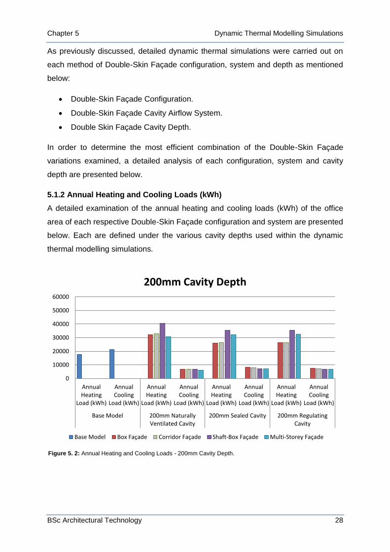
5.1.2 Annual Heating and Cooling Loads (kWh)
A detailed examination of the annual heating and cooling loads (kWh) of the office
area of each respective Double-Skin Façade configuration and system are presented
below. Each are defined under the various cavity depths used within the dynamic
thermal modelling simulations.
Figure 5. 2: Annual Heating and Cooling Loads - 200mm Cavity Depth.

Chapter 5 Dynamic Thermal Modelling Simulations
BSc Architectural Technology 29
0
10000
20000
30000
40000
50000
60000
Annual Heating
Load (kWh)
Annual Cooling
Load (kWh)
Annual Heating
Load (kWh)
Annual Cooling
Load (kWh)
Annual Heating
Load (kWh)
Annual Cooling
Load (kWh)
Annual Heating
Load (kWh)
Annual Cooling
Load (kWh)
Base Model 600mm Naturally Ventilated Cavity
600mm Sealed Cavity 600mm Regulating Cavity
600mm Cavity Depth
Base Model Box Façade Corridor Façade Shaft-Box Façade Multi-Storey Façade
0
10000
20000
30000
40000
50000
60000
Annual Heating
Load (kWh)
Annual Cooling
Load (kWh)
Annual Heating
Load (kWh)
Annual Cooling
Load (kWh)
Annual Heating
Load (kWh)
Annual Cooling
Load (kWh)
Annual Heating
Load (kWh)
Annual Cooling
Load (kWh)
Base Model 1000mm Naturally Ventilated Cavity
1000mm Sealed Cavity 1000mm Regulating Cavity
1000mm Cavity Depth
Base Model Box Façade Corridor Façade Shaft-Box Façade Multi-Storey Façade
Figure 5. 3: Annual Heating and Cooling Loads - 600mm Cavity Depth.
Figure 5. 4: Annual Heating and Cooling Loads - 1000mm Cavity Depth.

Chapter 5 Dynamic Thermal Modelling Simulations
BSc Architectural Technology 30
Upon initial review of the annual heating and cooling loads (kWh) within the office
area of the Hawkins House Redevelopment, it is clear that the conventional single-
skin façade base model has a greater demand on annual cooling loads than that of
heating loads.
However, in each of the various Double-Skin Façade simulations carried out it is
clear that the annual heating load demand is substationally greater than that of the
cooling load. This would suggest that although the heating demand associated with a
Double-Skin Façade is increased compared to a conventional single-skin façade, the
concept of a thermal buffer utilising the stack effect to remove excessive heat within
the cavity reduces the cooling loads significantly.
Due to this fact, overall annual energy consumption in relation to Double-Skin
Façade construction may be greater than that of a conventional single-skin façade
due to the increased heating loads. However, According to The European Energy
(Portal., 2013), as of November 2012 in Ireland, Industry prices per kWh for natural
gas (heating demands) and electricity (cooling demands) are €0.03852 and
€0.09618 respectively. This is an important economical aspect to consider as the
costs associated with the heating and cooling of a building has a ratio of
approximately 3:1. As a result, due the increased cooling load demand of a
conventional single-skin façade construction, the use of a Double-Skin Façade in
reality still provides a more cost effective method of façade construction in terms of
consumption of energy. A detailed account of the annual cost, and loads in relation
to energy consumption of each scenario can be seen in Appendix 3 (table 3.3-3.14).
5.1.3 Annual Energy Consumption (kWh/m²)
The annual energy consumption within the office area of the Hawkins House
redevelopment is presented below under the various Double-Skin Façade
configurations evaluated (A Box Façade, Corrdidor Façade and a Multi-Storey
Façade configuration).
The results are presented as per square metre of floor area (total floor area
852.44m²) This is necessary in order to determine and easily compare the overall
performance of each Double-Skin Façade configuration in greater detail.

Chapter 5 Dynamic Thermal Modelling Simulations
BSc Architectural Technology 31
Base Model 200mm 600mm 1000mm
Base Model 45.366
Naturally Ventilated 45.536 49.049 51.629
Sealed Cavity 40.077 41.452 42.345
Regulating Cavity 39.662 40.984 41.967
0.000
10.000
20.000
30.000
40.000
50.000
60.000
70.000
80.000
An
nu
al E
ne
rgy
Co
nsu
mp
tio
n (
Kw
h/m
²)
Box Façade
Base Model 200mm 600mm 1000mm
Base Model 45.366
Naturally Ventilated 46.348 47.323 48.764
Sealed Cavity 40.239 40.451 41.445
Regulating Cavity 39.510 39.652 40.576
0.000
10.000
20.000
30.000
40.000
50.000
60.000
70.000
80.000
An
nu
al E
ne
rgy
Co
nsu
mp
tio
n (
Kw
h/m
²) Corridor Façade
Figure 5. 5: Box Façade – Annual Energy Consumption (kWh/m²).
Figure 5. 6: Corridor Façade – Annual Energy Consumption (kWh/m²).

Chapter 5 Dynamic Thermal Modelling Simulations
BSc Architectural Technology 32
Base Model 200mm 600mm 1000mm
Base Model 45.366
Naturally Ventilated 55.439 58.238 72.292
Sealed Cavity 49.762 50.406 45.559
Regulating Cavity 49.584 50.088 45.175
0.000
10.000
20.000
30.000
40.000
50.000
60.000
70.000
80.000
An
nu
al E
ne
rgy
Co
nsu
mp
tio
n (
Kw
h/m
²)
Shaft-Box Façade
Base Model 200mm 600mm 1000mm
Base Model 45.366
Naturally Ventilated 43.132 44.692 44.702
Sealed Cavity 46.234 39.164 38.887
Regulating Cavity 45.791 38.554 38.226
0.000
10.000
20.000
30.000
40.000
50.000
60.000
70.000
80.000
An
nu
al E
ne
rgy
Co
nsu
mp
tio
n (
Kw
h/m
²)
Multi-Storey Façade
Figure 5. 7: Shaft-Box Façade – Annual Energy Consumption (kWh/m²).
Figure 5. 8: Multi-Storey Façade – Annual Energy Consumption (kWh/m²).

Chapter 5 Dynamic Thermal Modelling Simulations
BSc Architectural Technology 33
Upon review of the annual energy consumption of each Double-Skin Facade
configuration examined within the office area of the Hawkins House Redevelopment,
it is clear that the configuration which is performing the least efficiently in terms of
annual energy consumption is the Shaft-Box Façade configuration.
As such, the least efficient variation of the Shaft-Box Façade configuration examined
is the 1000mm naturally ventilated cavity. The annual energy consumption has a
value of 72.292 kWh/m², approximately 62% less efficient than the conventional
single-skin base model (45.366 kWh/m²).
As highlighted in Appendix 3 (table 3.5) the detailed cost analysis highlights that this
elevated value is attributed to by high annual heat loading demands (54,757.8 kWh)
and as a result, is the only configuration which is more expensive per annum than
the base model of the conventional single-skin façade.
Due to the nature of the Shaft-Box Façade, ie. dependent on various shafts to induce
the stack effect and cause air flow from the box elements in order to remove
excessive heat from the cavity (see figure 5.9). The high heating load may be as a
result of excessive airflow through the cavity due to a combination of the elevated
exposed façade of the office are (wind effects) and due to the large depth (1000mm)
of the naturally ventilated cavity.
In conclusion, the various dynamic
thermal modelling simulations carried
out on each respective Double-Skin
Façade configuration, cavity airflow
system and depth are presented above.
Through the results obtained from the
simulations, the optimal combination of
Double-Skin Façade construction is to
be identified in order to provide a
quantified conclusion on the most
efficient method of construction for use
within a temperate climate.
Figure 5. 9: Shaft-Box Façade Configuration – Airflow Concept.

6.0 Conclusions and Recommendations
BSc Architectural Technology 34
6.0 Conclusions and Recommendations
Through the results obtained within the dynamic thermal modelling simulations, as
discussed in the previous chapter, this chapter aims to provide a recommendation as
to which is the most energy efficient combination of Double-Skin Façade
configuration, system and depth of cavity to be utilised in an office building in a
temperate climate.
6.1 Comparison of Façade Configuration Energy Consumption
As highlighted within the various results in the previous chapter, the annual energy
consumption (kWh/m²) within the office area of the Hawkins House redevelopment
was presented under each of the four Double-Skin Façade configurations evaluated
within the dynamic thermal modelling simulations (see figures 5.5-5.8).
In order to determine which Double-Skin Façade configuration and cavity airflow
system is achieving the highest degree of efficiency in relation to energy
consumption, each of the best case scenarios from the four figures of results in
relation to façade configuration are shown together below in Table 6.1:
Figure 6. 1: Annual Energy Consumption – Facade Efficiency Comparison.
Box Façade Corridor Façade
Shaft-Box Façade
Multi-Storey Façade
Regulating Cavity 200mm 39.662 39.510
Regulating Cavity 1000mm 45.175 38.226
34.000
36.000
38.000
40.000
42.000
44.000
46.000
An
nu
al E
ne
rgy
Co
nsu
mp
tio
n (
kWh
/m²)
Façade Efficiency

6.0 Conclusions and Recommendations
BSc Architectural Technology 35
200mm 600mm 1000mm 1200mm 1400mm 1800mm
Multi-Storey Façade 45.791 38.554 38.226 38.201 38.312 38.937
34.000
36.000
38.000
40.000
42.000
44.000
46.000
48.000
An
nu
al E
ne
rgy
Co
nsu
mp
tio
n (
kWh
/m²)
Multi-Storey Façade - Optimal Cavity Depth
As indicated above, each of the best case scenarios of the Double-Skin Façade
configurations and systems evaluated are utilising a regulating cavity, underlining its
efficiency as opposed to the utilisation of a naturally ventilated or sealed cavity.
However, the 1000mm Multi-Storey Double-Skin Façade with a regulating cavity is
the most efficient façade construction combination evaluated. This combination
achieved an annual energy consumption value of 38.226 kWh/m², an increase in
efficiency of approximately 16% as opposed to the base model utilising a
conventional single-skin façade (45.366 kWh/m²).
In order to determine the most efficient combination of the Multi-Storey Double-Skin
Façade with a regulating cavity in terms of energy consumption a number of
additional dynamic thermal modelling simulations were undertaken at increased
cavity depths of 1200mm, 1400mm and finally 1800mm. These calculations were
performed to identify and establish the optimal depth of the cavity in terms of energy
consumption. A comparison of the energy consumption in relation to the cavity
depths is shown below in table 6.2:
Figure 6. 2: Multi-Storey Façade Regulating Cavity – Determination of Optimal Cavity Depth.

6.0 Conclusions and Recommendations
BSc Architectural Technology 36
0.00 500.00 1000.00 1500.00 2000.00 2500.00 3000.00
1000mm
1200mm
Base Model
Annual Energy Consumption Cost (€)
1000mm 1200mm Base Model
Base Model 2711.34
Multi-Storey Cavity 1624.76 1636.19
Multi-Storey Façade - Optimal Cavity Depth
As indicated above in figure 6.2, the optimal cavity depth of the Multi-Storey Double-
Skin Façade with a regulating cavity is located at a depth of approximately 1100mm.
Initially, the graph indicates a steady increase in energy efficiency of the Double-Skin
Façade between the respective depths of 200mm and 600mm. The energy efficiency
then gradually begins to stabilise between the respective depths of 600mm and
1200mm, before reducing in efficiency at an approximate depth of 1200mm. A
steady decrease in efficiency between the respective depths of 1200mm and
1400mm becomes considerably more substantial beyond a depth of 1400mm to
1800mm.
This trend indicates that beyond a certain depth of cavity (1200mm) the efficiency of
the Double-Skin Façade begins to decrease, becoming less efficient the greater the
depth, thus highlighting the importance of the need for careful consideration when
designing the dimensional parameters of a Double-Skin Façade construction.
However, even though the optimal cavity depth of the Multi-Storey Double-Skin
Façade with a regulating cavity is approximately 1100mm, there is only a relatively
small difference in terms of annual energy consumption between a cavity of 1000mm
and 1200mm (25 kWh/m²).
As such, further exploration in relation to the annual cost (€) of the office area in
relation to energy consumption of each depth is shown below in figure 6.3:
Figure 6. 3: Annual Energy Consumption Cost – Optimal Cavity Depth.

6.0 Conclusions and Recommendations
BSc Architectural Technology 37
As highlighted above in figure 6.3, the difference in cost of the annual energy
consumption between the 1000mm and 1200mm Multi-Storey regulating cavity is a
relatively unimpressive €11.43.
However, a substantial difference in the cost of annual energy consumption of the
office area of €1,086.58 exists between the 1000mm cavity depth and the
conventional single-skin façade base model.
This indicates a substantial improvement of 31% in annual energy efficiency
between the conventional single-skin façade base model and the Multi-Storey
Double-Skin Façade with a 1000mm regulating cavity system.
6.2 Recommendations – Optimum Cavity Depth
The primary aim of this research was to determine and evaluate the effect in which
various configurations, systems and cavity depths of Double-Skin Façade
construction plays in relation to overall the energy consumption of an office building
within a temperate climate.
Additionally, to establish and determine the optimal combination of Double-Skin
Façade configuration, cavity airflow system and cavity depth in relation to overall
building energy consumption for use within the façade of the office area of the
Hawkins House redevelopment.
Through the careful analysis of the results of the simulations of the dynamic thermal
modelling of the variations and combinations of Double-Skin Façade construction, it
is clear that the most efficient method of Double-Skin Façade construction for use
within the office area of the Redevelopment of Hawkins Hawkins House is comprised
of the following main parameters:
A Multi-Storey Double Skin Façade Configuration.
A Regulating (mixed mode) cavity ventilation system.
A 1000mm cavity depth.
In conclusion, this combination of Double-Skin Façade construction provides
increased annual percentage efficiency in terms of energy consumption of 31%, and
a substantial cost saving of €1,086.58 as opposed to the use of a conventional
single-skin façade.

6.0 Conclusions and Recommendations
BSc Architectural Technology 38
6.3 Areas for Further Research
Double-Skin Façade construction has excellent potential for a further decrease in
overall building energy consumption in a wide range of research areas. Some of the
main areas for further thought and research arising from this dissertation are:
The potential harnessing of heat generated within the Double-Skin Façade cavity for
reintegration within the building. As the temperature within the cavity can reach
extremely high temperatures, the ability to collect such heat is a viable option as
opposed to releasing the heat generated back into the environment. This can be
achieved through various methods in which the overall energy consumption of the
building can be decreased further, such as:
The use of phase-change materials.
The use of mechanical heat recovery systems.
Another viable method of potentially reducing overall building energy consumption is
the use and integration of photovoltaic panels within the external skin of the Double-
Skin Façade. This is an interesting area of further research as the high levels solar of
exposure in which double-skin facades receive provides an ideal situation for the
collection of solar energy and generation of electricity while also providing often
much needed solar shading to the building interior.
Another area of further research in
which the possibility of building
energy consumption can be
decreased is through the use of an
external skin comprised of
horizontal slats of transparent and
translucent glass (see figure 6.4).
The orientation of this method of
external skin configuration is
regulated by the use of a building
management system and as such
construction protects the interior of
building from large amounts of solar
radiation and thus regulates the interior temperature reducing overall cooling loads.
Figure 6. 4: Horizontal Pivoting Transparent Slats (Teuxido,
2013).

References
BSc Architectural Technology 39
References
12792., B. E. (2003). Ventilation for buildings, Symbols, terminology and graphical symbols.
Aksamija, A. Context Based Design of Double Skin Facades: Perkins + Will Research Journal.
ArchiExpo. (2003). from http://archiexpo.com/prod/feal-croatia-itd/ventilated-aluminium-facades-57866-587842.html
Arons, D. (2000). Properties and Applications of Double-Skin Building Facades. Massachusetts Institute of Technology.
Baker, N. (2013). Natural ventilation - stack ventilation. from http://www.architecture.com/SustainabilityHub/Designstrategies/Air/1-2-1-2-Naturalventilation-stackventilation.aspx
Bayram, A. (2003). Energy Performance of Double Skin Facades In Intelligent Office Buildings: A Case Study in Germany., The Middle East Technical University.
BBRI, B. B. R. I. (2004). Ventilated Double Facades - Classification and Illustration of Facade Concepts: Department of Building Physics, Indoor Climate and Building Services.
Caine, T. (2013). Green Buildings: The Cambridge Public Library. Consultants, B. (2013). Building Envelope. from
http://www.bauerconsultbotswana.com/7_BuildingEnvelope.pdf Crespo, A. M. L. (2002). History of the Double-Skin Facade: Harvard School of
Design. Dickson, A. (2003). Modelling Double-Skin Facades. University of Strathclyde,
Glasgow, Scotland. Gonchar, J. (2013). More Than Skin Deep | From Architectural Record | Originally
published in the July 2010 issue of Architectural Record | Architectural Record's Continuing Education Center. from http://continuingeducation.construction.com/article.php?L=5&C=685&P=4
Heimrath, R., Hengsberger, H., Mach, T., Streicher, W., & Waldner, R. (2005). Best Practice for Double-Skin Facades: Institute of Thermal Engineering, Graz University of Technology.
King, D. (2010). Engineering a Low Carbon Built Environment. London: The Royal Academy of Engineering.
Lee, E., Selkowitz, S., Bazjanac, V., Inkarojrit, V., & Kohler, C. (2002). High-Performance Commercial facades: Ernest Orlando lawerence Berkeley National Laboratory.
Oesterle, E., Lieb, R.-D., Lutz, M., & Heusler, W. (2001). Double-Skin Facades - Integrated Planning: Prestel.
Palmer, D. (2011). A Decision Making tool, Guidance and Considerations to Optimise Energy Consumption and Occupant Comfort when Replacing Facades on Exisiting Buildings. The University of Bath., Bath.
Permasteelisa, G. (2013). Closed Cavity Facades. from http://josef-gartner.permasteelisagroup.com/about-gartner/products-services/closed-cavity-facades/
Poizaris, H. (2006). Double-Skin Facades - A literature Review: Lund University, Lund Institute of Technology.
Portal., E. E. (2013). Renewable energy in final energy consumption. from http://www.energy.eu/

References
BSc Architectural Technology 40
Saelens, D. (2002). Energy Performance Assessment of Single Story Multiple-Skin Facades.
Solla, I. F. (2013). Façades Confidential: 11/01/2011 - 12/01/2011. from http://facadesconfidential.blogspot.ie/2011_11_01_archive.html
Streicher, W., Heimrath, R., Hengsberger, H., Mach, T., Waidner, R., Flamant, G., et al. (2007). On the Typology, Costs, Energy Performance, Environmental Quality and Operational Characteristics of Double Skin Facades in European Buildings. [Article]. Advances in Building Energy Research, 1, 1-28.
Tascón, & Hernandez., M. (2008). Experimental And Computational Evaluation Of Thermal Performance And Overheating In Double Skin Facades: University of Nottingham.
Teuxido, C. (2013). Double skin façade of Agbar Tower in Barcelona, by Jean Nouvel [226].
Uuttu, S. (2001). Study of Current Structures in Double-Skin Facades. Helsinki University of Technology, Helsinki.
Wolfe, R. (2013). The Sociohistoric Mission of Modernist Architecture:.

Appendix 1
BSc Architectural Technology 1
Appendix 1: The History of Double-Skin Façades
Although the concept of Double-Skin Façades is not new, there is a growing
tendency within the construction industry for architects and engineers to incorporate
them into projects. Information on the history of Double-Skin Façades can be
obtained through a wide range of articles, books, reports, etc.
However according to (Saelens, 2002) in 1849, Jean-Baptiste Jobard, the director of
The Industrial Museum in Brussels, was the first person to describe the idea of a
mechanically ventilated multiple-skin façade. He mentioned his theory of how ‘’in
winter hot air should be circulated between two glazing, while in summer it should be
cold air’’. His theory however is not mentioned for another 65 years. In 1914, Paul
Scheerbaert mentions a similar idea in his book “Glasarchitectur”.
It is apparent that as early as the 19th
century consideration was given to the
performance of buildings, especially in
terms of thermal performance. One can
still find an example of this in old
farmhouses with box-type windows in
Mürren, Switzerland. It is possible to open
the box windows but also remove the outer
casements completely. They are
constructed in such a manner that in
summer, the inner-casements can be opened and the outer layer of glazing
removed. This allows an adaptation of the building envelope to the climatic
conditions (Oesterle, et al., 2001).
The first example of a Double-Skin wall
construction can be found from the year
1903 in the Steiff Factory in Giengen,
Germany. The aim of the project was to
maximise day lighting but to also to
provide protection from the harsh climate
Appendix 1. 2: Famhouse Box-Type Windows in
Mürren, Switzerland (Oesterle, et al., 2001).
Appendix 1. 1: Steiff Factory Giengen, Germany. Circa 1904 (Solla, 2013).

Appendix 1
BSc Architectural Technology 2
of the region. In order to achieve these goals a three storey structure was erected. It
comprised of a ground floor acting as storage space with two upper floors as work
areas. The building was regarded as a complete success and thus two extensions
were built in 1904 and 1908. They were constructed using the same double-skin
façade construction method but timber was used as the main structural material due
to budgetary reasons. All buildings are still in use today (Heimrath, Hengsberger,
Mach, Streicher, & Waldner, 2005).
Also in the year 1903, the Post Office Savings Bank in Vienna, Austria, held a
competition for the design of its main building. Otto Wagner won the competition and
the bank was built in two construction phases from 1904 to 1912. It contained a
double-skin aluminium skylight supported by steel columns in the main hall (Poizaris,
2006).
By the end of the 1920’s, double-skin façades began to advance with other
considerations in mind. There are two main examples which can be used to highlight
this (Uuttu, 2001).
In 1928 in Russia, Moisei Ginzburg
investigated the possible use of double-
skin sections in the communal service
blocks of the Narkomfin housing building,
in Moscow. Ginzburg was very interested
in the technical aspects of windows and
how to achieve greater performance
standards (Uuttu, 2001).
Also at the same time in Moscow, Le Corbusier was in the
process of designing the Centrosoyus. The following year in
Paris he would then undertake the design of La Cité de
Refuge and the Immeuble Clarte. Each of the initial projects
were designed with Le Corbusier concept of ‘’mûr
neutralisant’’. His theory predicted that the transmission
losses and gains would disappear by the circulation of air at
room temperature through the building cavity. However his
Appendix 1. 3: Narkomfin Housing Building, Moscow,
Russia. Circa 1928 (Wolfe, 2013).
Appendix 1. 4: Corbusier Sketch
Illustrating Ideas (Tascón & Hernandez., 2008).

Appendix 1
BSc Architectural Technology 3
system was deemed as too expensive and inefficient to build and thus the idea was
abandoned (Saelens, 2002).
However, there was then little or no progress made in double-skin façade
construction up until the late 70’s and early 80’s of the century (Poizaris, 2006). The
oil crisis’ of 1973 and 1979 had a positive effect and resulted in a boost on the
development rate of insulating glazing as greater awareness on energy consumption
became evident. Many innovative improvements to the technology were made with
the introduction of low-emissivity coating and inert gas filled cavities. In the same
period an awareness grew on the effects of external shading, thermal mass and the
role of ventilation in relation to building performance standards (Dickson, 2003).
During the 80’s double-skin façades finally began to gain momentum within the
construction industry. Most of the façades constructed during this era were designed
with consideration to environmental factors, such as the offices of Leslie and
Godwin, or with the aesthetic effect of multiple layers of glass (Poizaris, 2006).
During the 90’s there were two main factors which began to have a large influence of
the proliferation of double-skin façades. The increase of environmental concerns
began to influence architectural design not only from a technical standpoint but also
due to political influences that make ‘’green buildings’’ a good image for corporate
architecture. In addition the rapid development of software and hardware allowed
designers to carry out highly complex calculations in order to effectively design
façades (Heimrath, et al., 2005).
As a result these factors make double-skin façades an ideal option for use in high
rise buildings. Typically they are provided with a large budget and the aim of
achieving an environmentally friendly image. Another aspect which makes them
particularly effective with high-rise buildings is the fact that a double-skin façade
allows windows to be opened despite strong wind conditions incurred on certain
floors due to their height within the building.
Examples of such can be found in RWE AG Headquarters by Ingenhoven, Overdiek
Kahlen und Partner, the Commerzbank Headquarters by Foster and Partners, both
of which were completed in Germany in 1997. The work of Renzo Piano in the Debis
Tower in 1998 is a less extreme example of this tendency. The firm carried out a

Appendix 1
BSc Architectural Technology 4
thorough environmental analysis of the façades in the building. As a result the idea
of creating an environmentally friendly skyscraper was progressed by the concept of
allowing the skin to adapt to the individual requirements (Crespo, 2002).

Appendix 2
BSc Architectural Technology 1
Appendix 2: IES Virtual Environment User Interface
Appendix 2. 1: Office Room Conditions.
Appendix 2. 2: Double-Skin Façade Room Conditions.

Appendix 2
BSc Architectural Technology 2
Appendix 2. 4: Double-Skin Façade MacroFlo Opening Template – Naturally ventilated Cavity.
Appendix 2. 3: Double-Skin Façade MacroFlo Opening Template – Sealed Cavity.

Appendix 2
BSc Architectural Technology 3
Appendix 2. 5: Double-Skin Façade MacroFlo Opening Template – Regulating Cavity.

Appendix 3
BSc Architectural Technology 1
Base Model
Box Façade
Corridor Façade
Shaft-Box Façade
Multi-Storey Façade
0
10
20
30
40
50
60
70
Naturally Ventilated
Cavity
Sealed Cavity Regulating
Cavity Naturally
Ventilated Cavity
Sealed Cavity Regulating
Cavity Naturally
Ventilated Cavity
Sealed Cavity Regulating
Cavity
Base Model 200mm
600mm
1000mm
Base Model
Box Façade
Corridor Façade
Shaft-Box Façade
Multi-Storey Façade
Appendix 3: Double-Skin Façade – Energy Consumption
and Cost Analysis
A detailed analysis of the various results obtained within the
thermal dynamic simulations is highlighted within the current
appendix, in addition to a number of detailed cost analysis
calculations. The results obtained include:
Natural Gas Consumption (kWh).
Electricity Consumption (kWh).
Annual Energy Consumption (mWh).
Annual Energy Consumption (kWh/m²).
Annual Energy Consumption Cost (€).
Percentage Efficiency (Opposed to Base Model).
An overview of the annual energy consumption (mWh) of each
respective Double-Skin Façade combinations is available to the
right in Appendix 3 Figure 3.1.
Dublin Experimental Parameters
Building Area (m²) 852.44 Natural Gas Price (€) 0.03852 Electricity Price (€) 0.09618
Project Baseline (kwh/m²) 110, 210 Appendix Table 3.1: Base Model Experimental Parameters
Dublin (Curtain Wall Construction) Cost (€) Natural Gas Consumption (kWh) 17484
€ 673.48
Electricity Consumption (kWh) 21187.9
€ 2,037.85
Annual Energy Consumption (mWh) 38.6719
€ 2,711.34
Energy Consumption ( kWh/m²) 45.36612548
€ 3.18
Appendix Table 3.2: Base Model Examination.
Appendix 3. 1: Annual Energy Consumption Overview (mWh).

Appendix 3
BSc Architectural Technology 2
Dublin (200mm Naturally Ventilated Cavity)
Façade Configuration Natural Gas Consumption
(kWh) Electricity Consumption (kWh) Annual Energy Consumption (mWh) Energy Consumption (kWh/m²) Annual Cost (€)
Box Facade 32001.7 6815 38.8167 45.5359908 €
1,888.17
Corridor Facade 32795.5 6713.8 39.5093 46.348482 €
1,909.02
Shaft-Box Facade 40623.9 6634.3 47.2582 55.43874056 €
2,202.92
Multi-Storey Facade 30563.1 6204 36.7671 43.1315987 €
1,773.99 Appendix Table 3.3: IES Test Results
Dublin (600mm Naturally Ventilated Cavity)
Façade Configuration Natural Gas Consumption
(kWh) Electricity Consumption (kWh) Annual Energy Consumption (mWh) Energy Consumption (kWh/m²) Annual Cost (€)
Box Facade 35227.6 6583.9 41.8115 49.04919994 €
1,990.21
Corridor Facade 33778 6562 40.34 47.32297874 €
1,932.26
Shaft-Box Facade 42999 6645.5 49.6445 58.23811647 €
2,295.49
Multi-Storey Facade 31724.1 6373.4 38.0975 44.69229506 €
1,835.01 Appendix Table 3.4: IES Test Results Dublin (1000mm Naturally Ventilated Cavity)
Façade Configuration Natural Gas Consumption
(kWh) Electricity Consumption (kWh) Annual Energy Consumption (mWh) Energy Consumption (kWh/m²) Annual Cost (€)
Box Facade 37432.6 6578.4 44.011 51.6294402 €
2,074.61
Corridor Facade 35048.4 6519.9 41.5683 48.76390127 €
1,977.15
Shaft-Box Facade 54757.8 6866.9 61.6247 72.29212613 €
2,769.73
Multi-Storey Facade 31800.4 6305.1 38.1055 44.70167988 €
1,831.38

Appendix 3
BSc Architectural Technology 3
Appendix Table 3.5: IES Test Results
Dublin (200mm Sealed Cavity)
Façade Configuration Natural Gas Consumption
(kWh) Electricity Consumption (kWh) Annual Energy Consumption (mWh) Energy Consumption (kWh/m²) Annual Cost (€)
Box Facade 26065.3 8098.3 34.1636 40.0774248 €
1,782.93
Corridor Facade 26500.1 7801.4 34.3015 40.23919572 €
1,771.12
Shaft-Box Facade 35437.4 6981.8 42.4192 49.76209469 €
2,036.56
Multi-Storey Facade 32331 7080.3 39.4113 46.2335179 €
1,926.37 Appendix Table 3.6: IES Test Results
Dublin (600mm Sealed Cavity)
Façade Configuration Natural Gas Consumption
(kWh) Electricity Consumption (kWh) Annual Energy Consumption (mWh) Energy Consumption (kWh/m²) Annual Cost (€)
Box Facade 27754.6 7580.8 35.3354 41.45206701 €
1,798.23
Corridor Facade 26992.5 7489.3 34.4818 40.45070621 €
1,760.07
Shaft-Box Facade 36119.5 6848.9 42.9684 50.40636291 €
2,050.05
Multi-Storey Facade 26258.8 7126.1 33.3849 39.16392943 €
1,696.88 Appendix Table 3.7: IES Test Results
Dublin (1000mm Sealed Cavity)
Façade Configuration Natural Gas Consumption
(kWh) Electricity Consumption (kWh) Annual Energy Consumption (mWh) Energy Consumption (kWh/m²) Annual Cost (€)
Box Facade 28779.1 7317.4 36.0965 42.34491577 €
1,812.36
Corridor Facade 27933.2 7395.9 35.3291 41.44467646 €
1,787.32
Shaft-Box Facade 32049.6 6786.3 38.8359 45.55851438 €
1,887.26
Multi-Storey Facade 26152.2 6996.3 33.1485 38.88660786 €
1,680.29
Appendix Table 3.8: IES Test Results

Appendix 3
BSc Architectural Technology 4
Dublin (200mm Regulating Cavity)
Façade Configuration Natural Gas Consumption
(kWh) Electricity Consumption (kWh) Annual Energy Consumption (mWh) Energy Consumption (kWh/m²) Annual Cost (€)
Box Facade 26364 7445.7 33.8097 39.66226362 €
1,731.67
Corridor Facade 26525.4 7154.1 33.6795 39.5095256 €
1,709.84
Shaft-Box Facade 35574.5 6693.3 42.2678 49.58448688 €
2,014.09
Multi-Storey Facade 32363.7 6670.5 39.0342 45.79114073 €
1,888.22 Appendix Table 3.9: IES Test Results
Dublin (600mm Regulating Cavity)
Façade Configuration Natural Gas Consumption
(kWh) Electricity Consumption (kWh) Annual Energy Consumption (mWh) Energy Consumption (kWh/m²) Annual Cost (€)
Box Facade 28170.1 6766.3 34.9364 40.98399887 €
1,735.89
Corridor Facade 27015 6786.3 33.8013 39.65240955 €
1,693.32
Shaft-Box Facade 36259 6438.3 42.6973 50.08833466 €
2,015.93
Multi-Storey Facade 26281.7 6583.6 32.8653 38.55438506 €
1,645.58 Appendix Table 3.10: IES Test Results
Dublin (1000mm Regulating Cavity)
Façade Configuration Natural Gas Consumption
(kWh) Electricity Consumption (kWh) Annual Energy Consumption (mWh) Energy Consumption (kWh/m²) Annual Cost (€)
Box Facade 29326.5 6447.6 35.7741 41.96670733 €
1,749.79
Corridor Facade 27955.7 6632.6 34.5883 40.57564169 €
1,714.78
Shaft-Box Facade 32220.3 6288.8 38.5091 45.17514429 €
1,845.98
Multi-Storey Facade 26175.9 6409.5 32.5854 38.2260335 €
1,624.76
Appendix Table 3.11: IES Test Results

Appendix 3
BSc Architectural Technology 5
Appendix Table 3.14: IES Test Results
Dublin (1200mm Regulating Cavity)
Façade Configuration Natural Gas Consumption
(kWh) Electricity Consumption (kWh) Annual Energy Consumption (mWh) Energy Consumption (kWh/m²) Annual Cost (€)
Multi-Storey 25942 6622 32.564 38.2009291 €
1,636.19 Appendix Table 3.12: IES Test Results
Dublin (1400mm Regulating Cavity)
Façade Configuration Natural Gas Consumption
(kWh) Electricity Consumption (kWh) Annual Energy Consumption (mWh) Energy Consumption (kWh/m²) Annual Cost (€)
Multi-Storey 26006 6652.4 32.6584 38.31167003 €
1,641.58 Appendix Table 3.13: IES Test Results
Dublin (1800mm Regulating Cavity)
Façade Configuration Natural Gas Consumption
(kWh) Electricity Consumption (kWh) Annual Energy Consumption (mWh) Energy Consumption (kWh/m²) Annual Cost (€)
Multi-Storey 26584 6607.2 33.1912 38.93669936 €
1,659.50