a comparison of two methods to articulate a …...facebow, owes its development to a great number of...
TRANSCRIPT

Marquette Universitye-Publications@Marquette
Master's Theses (2009 -) Dissertations, Theses, and Professional Projects
A Comparison of Two Methods to Articulate aMaxillary Cast with Lateral CephalometryLaura H. LuxMarquette University
Recommended CitationLux, Laura H., "A Comparison of Two Methods to Articulate a Maxillary Cast with Lateral Cephalometry" (2014). Master's Theses(2009 -). Paper 252.http://epublications.marquette.edu/theses_open/252
A COMPARISON OF TWO METHODS TO ARTICULATE A MAXILLARY CAST WITH LATERAL CEPHALOMETRY.
By
Laura H. Lux D.D.S
A Thesis submitted to the Faculty of the Graduate School,
Marquette University,
in Partial Fulfillment of the Requirements for
the Degree of Master of Science
Milwaukee, WI
May 2014

ABSTRACT A COMPARISON OF TWO METHODS TO ARTICULATE A MAXILLARY CAST WITH
LATERAL CEPHALOMETRY
Laura H. Lux D.D.S
Marquette University, 2014
The Kois Dento-Facial Analyzer, an arbitrary articulation system, is used by clinicians to articulate and evaluate clinical cases. There is, however, limited information for understanding how the Kois Dento-Facial Analyzer should be utilized. Dr. Kois and Dr. Lee originally patented the device in 2003 yet there is essentially no evidence-based research in the literature. The purpose of this study was to evaluate the outcomes of articulating the maxillary cast using the Kois Dento-Facial Analyzer in three-dimensions as compared to the position of the cast when using Panadent’s Pana-Mount Facebow.
Fifteen dried human skulls were used as test subjects. Maxillary diagnostic impressions were made on each skull as well as lateral cephalometric radiographs. Each diagnostic cast was articulated on a Panadent articulator according to the manufacturer’s instructions by means of the Kois Dento-Facial Analyzer as well as the Pana-Mount facebow. Standardized photographs of each articulation were then taken from a lateral view. From the cephalometric radiograph, key landmarks and measurements were made including the distance from the condylar center to the incisal edge and the occlusal plane angle relative to Frankfort Horizontal Plane. From the photographs taken of each articulation, the distance from the articular centers to the incisal edge position was measured, as was the occlusal plane angle relative to Frankfort Horizontal Plane. Finally, the three-dimensional position of each articulation was located and compared by means of the Panadent CPI III device.
Statistical analysis was completed for the data collected. From this study, the following conclusions were made:
1. The Kois Dento-Facial Analyzer articulates the maxillary cast in a position that is not statistically different to the Pana-Mount facebow when comparing the incisal edge position and occlusal plane angle relative to Frankfort Horizontal.
2. Both the Kois Dento-Facial Analyzer and the Pana-Mount facebow locate the maxillary incisal edge position in a significantly different position compared to the skull.
3. Both the Kois Dento-Facial Analyzer and the Pana-Mount facebow produce occlusal plane angles that are not significantly different than the angle on the skull.
4. The three dimensional location of the maxillary cast varies approximately 8-10 mm at the condyles.

i
ACKNOWLEDGMENTS
Laura H. Lux D.D.S.
I would like to acknowledge the members of my thesis committee without whom this thesis would not be possible: Dr.’s Geoffrey Thompson, Kenneth Waliszewski, and Gerald Ziebert. I would also like to thank my family, specifically my husband Walter, my son Dylan, and my parents Richard and Mary Ann for being patient as I undertook this endeavor. Finally, I would like to thank Marquette University School of Dentistry, faculty and administration.
ii
TABLE OF CONTENTS
ACKNOWLEDGMENTS …...…………………………………………………….…….. i
TABLE OF CONTENTS………………………………………………………………... ii
LIST OF TABLES. ……………………………………………………………...………iii
LIST OF FIGURES………………………………………………………………………iv
CHAPTER
I. INTRODUCTION ………………………………………….……………...…….1
II. REVIEW OF THE LITERATURE……………………………………………....5
III. MATERIALS AND METHODS…………………………………………...…...21
IV. RESULTS……………………………………………………………...………..32
V. DISCUSSION…………………………………………………………………...36
VI. CONCLUSION………………………………………………………………….44
VII. APPENDIX A……………………………………………………………..…….45
VIII. BIBLIOGRAPHY…………………………………………..…………………...47
iii
LIST OF TABLES
Table 1: One-way ANOVA for distance.
Table 2: Least square means differences Tukey’s HSD.
Table 3: One-way ANOVA for angulation.
Table 4: Least square means differences Tukey’s HSD.
Table 5: One sample t-test, right side.
Table 6. Means comparison of Kois Dentofacial Analyzer and the facebow, right side.
Table 7: One sample t-test, left side.
Table 8. Means comparison of Kois Dentofacial Analyzer and the facebow, left side.
Table 9. Raw Data. CPI III
Table 11. Raw Data. Distance from the approximate condylar axis to the incisal edge position.
Table 12. Raw Data. Occlusal plane angle in degrees.

iv
LIST OF FIGURES
Figure 1. Representation of Reference Planes.
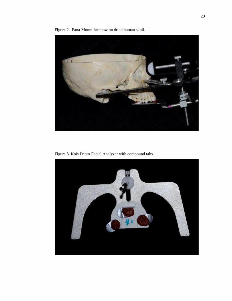
Figure 2. Pana-Mount facebow on dried human skull.
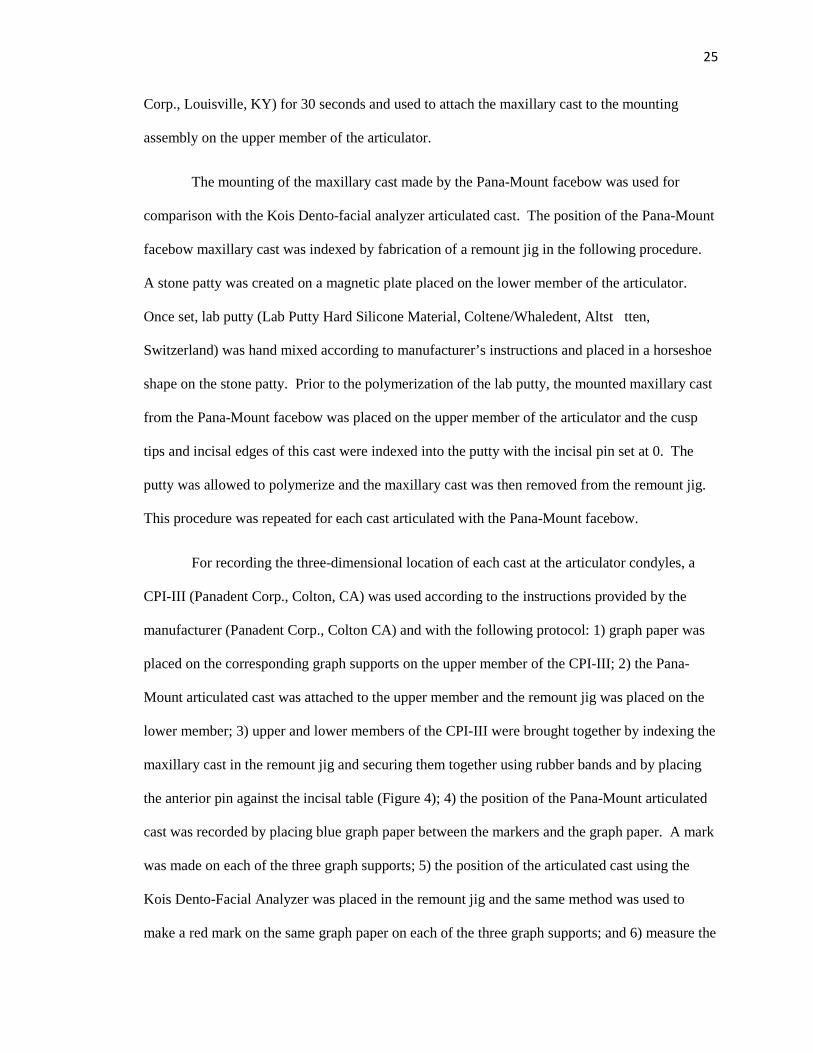
Figure 3. Kois Dento-Facial Analyzer with compound tabs
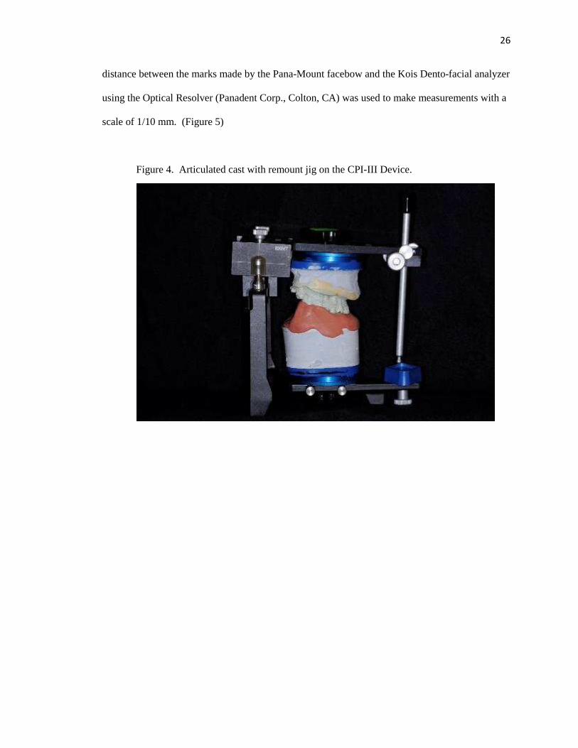
Figure 4. Articulated cast with remount jig on the CPI-III Device.
Figure 5. Example of graphical recording on CPI-III Device
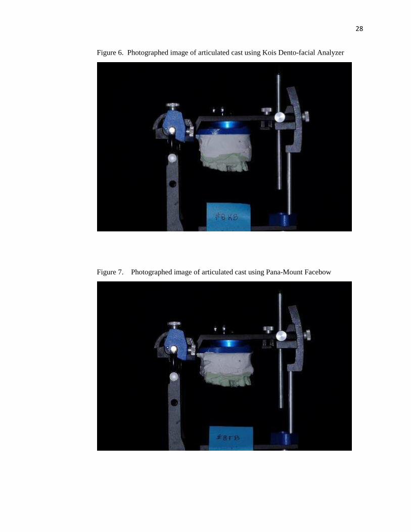
Figure 6. Photographed image of articulated cast using Kois Dento-facial Analyzer
Figure 7. Photographed image of articulated cast using Pana-Mount Facebow
Figure 8. Skull in Orthoceph machine
Figure 9. Cephalometric radiograph
Figure 10. Enlarged view showing arbitrary axis location
Figure 11. Diagram of Bonwill’s Theory
1
CHAPTER 1
INTRODUCTION
In the earliest years of restorative and prosthetic dentistry, restorations were created
directly in the mouth. This was challenging and time consuming for the dentist and patient alike.
With advances in material science, restorations fabricated on plaster replicas became the standard
for fixed and removable prosthodontics. The science of articulating casts developed in response to
a desire for fabricating restorations indirectly. Toward that end, articulators and facebows for
positioning casts were developed and oftentimes these devices were used in partnership to obtain
the desired results. Since the middle of the 19th century, few of the theories of articulation have
been changed.
An articulator is a mechanical instrument that represents the temporomandibular joints
and jaws, to which maxillary and mandibular casts may be attached to simulate some or all of the
mandibular movements (Academy of Prosthodontics, 2005). Articulators are further divisible
into four classes according to the Glossary of Prosthodontic Terms. A non-adjustable (Class I)
articulator is a simple holding instrument capable of accepting a single static registration; vertical
motion is only possible. Alternately, a Class II articulator is one that permits horizontal as well as
vertical motion but does not relate the motion to the temporomandibular joints. A semi-
adjustable (Class III) articulator simulates condylar pathways by using averages or mechanical
equivalents for all or part of the mandibular movement; these instruments allow for orientation of
the casts relative to the joints. Finally, the fully adjustable (Class IV) articulator is an instrument
that will accept three dimensional dynamic registrations; these instruments allow for orientation
of the casts to the temporomandibular joints and simulation of mandibular movements (Academy
of Prosthodontics, 2005).

2
Facebows are a caliper-like instrument used to record the spatial relationship of the
maxillary arch to osseous landmarks for the purpose of transferring this relationship to an
articulator. Another purpose is to transfer the opening axis of the mandible to the articulator.
Customarily, anatomic references are a transverse horizontal axis passing through the mandibular
condyles and one other selected point (Academy of Prosthodontics, 2005). Facebows are divided
into two types, kinematic or arbitrary. A kinematic facebow has adjustable calipers for locating
of the transverse horizontal axis of the mandible. The transverse horizontal is an axis that
connects the rotational centers of the right and left condyles; it is also known as the kinematic
axis. An arbitrary facebow, or earbow, is an instrument that uses an arbitrary axis, rather than the
true hinge axis for transferring the maxillary cast to the articulator. Typically an arbitrary
facebow uses the right and left external auditory meatus. Earbows provide an average anatomic
dimension between the external auditory meatus and the horizontal axis of the mandible
(Academy of Prosthodontics, 2005).
A horizontal reference plane may be established on the face with one anterior reference
point and two posterior reference points. It is from this plane that measurements of the posterior
anatomic determinants of occlusion and mandibular motion are made. Examples of horizontal
reference planes are Frankfort Horizontal, Axis Orbitale, Campers Plane, and the Esthetic
Reference Position (Figure 1).
3
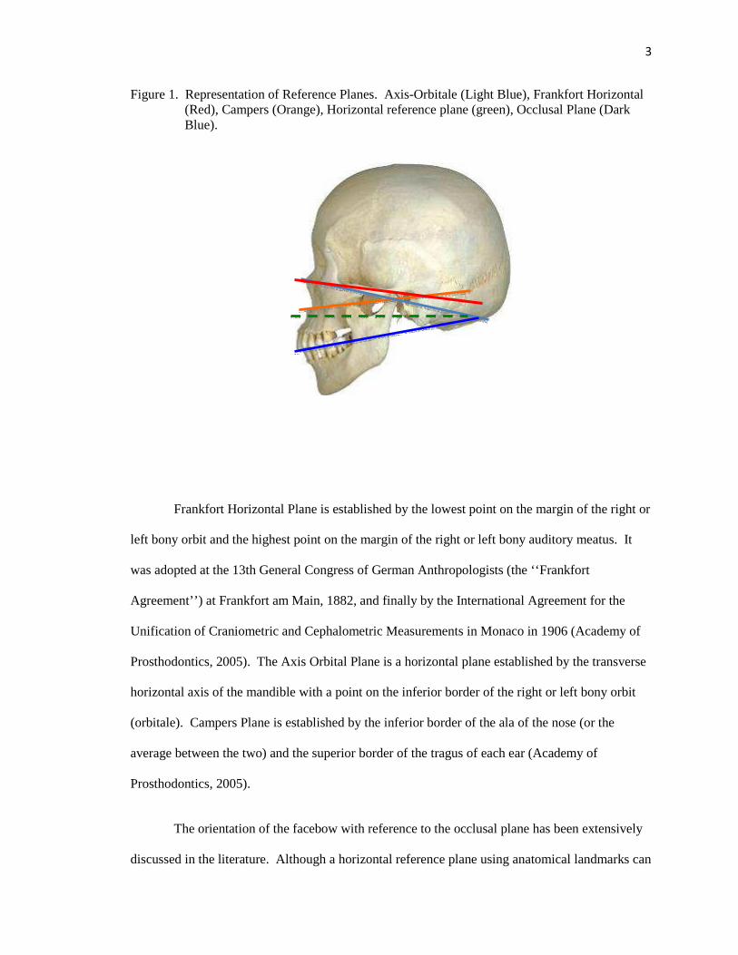
Figure 1. Representation of Reference Planes. Axis-Orbitale (Light Blue), Frankfort Horizontal (Red), Campers (Orange), Horizontal reference plane (green), Occlusal Plane (Dark Blue).
Frankfort Horizontal Plane is established by the lowest point on the margin of the right or
left bony orbit and the highest point on the margin of the right or left bony auditory meatus. It
was adopted at the 13th General Congress of German Anthropologists (the ‘‘Frankfort
Agreement’’) at Frankfort am Main, 1882, and finally by the International Agreement for the
Unification of Craniometric and Cephalometric Measurements in Monaco in 1906 (Academy of
Prosthodontics, 2005). The Axis Orbital Plane is a horizontal plane established by the transverse
horizontal axis of the mandible with a point on the inferior border of the right or left bony orbit
(orbitale). Campers Plane is established by the inferior border of the ala of the nose (or the
average between the two) and the superior border of the tragus of each ear (Academy of
Prosthodontics, 2005).
The orientation of the facebow with reference to the occlusal plane has been extensively
discussed in the literature. Although a horizontal reference plane using anatomical landmarks can
2
34
5
1
4
be used, it may not represent the erect head position of a patient on the articulator; therefore,
esthetic planes have been described. The Esthetic Reference Position is the position of the head
when an individual is sitting or standing erect with the head level and eyes fixed on the horizon.
This position can also be referred to as the Natural Head Position which was first described by
Broca as" the position of a standing man when his visual axis is horizontal” (Pitchford, 1991).
The design and application of the facebow has long been a topic of debate within the
dental community. Whether an arbitrary ear bow or a complex kinematic facebow should be
used, or even the use of a facebow at all, has often been a point of discussion between clinicians.
The device evaluated in this study, the Kois Dento-facial Analyzer, is an unconventional system
as its reference points are determined by esthetic parameters rather than anatomic ones. There is
interest in comparing this unconventional system to commonly accepted arbitrary facebows.
Why and how the Kois Dento-facial analyzer works has yet to be revealed and to date, there have
been no published studies establishing its validity. The undertaking of this Master’s thesis was
meant to begin that process.

5
CHAPTER 2
REVIEW OF THE LITERATURE
A facebow is a device that attempts to locate the maxillary cast in an orientation that
mimics that of the maxilla to the cranial base. More specifically, it records the position of the
maxilla in relation to an axis of rotation (Craddock, Symmons, 1952). This is key for creating
indirect oral prostheses with the same arc of closure exhibited by the patient. Designing such a
device did not happen overnight. Articulation, as influenced by the dental articulator and the
facebow, owes its development to a great number of people. While not all individuals created
facebows or articulators in the form that we are accustomed to today, each contributed elements
that allowed cast articulation and mandibular movement to evolve into a clinically useful
exercise.
In 1864, W. Bonwill described the “peculiar tripod arrangement of the lower jaw
forming an equilateral triangle” with the average dimensions of 4 inches when measuring from
the midpoint of the crest of the condyle to the point between the incisal edges of the lower central
incisors. He acknowledged that this dimension of 4 inches or approximately 100 mm might vary
slightly, “but never more than ¼ of an inch” (Bonwill, 1864). His rationale for this triangle was
that it was necessary, “for purpose of giving the largest number of muscles a chance to act on
both sides simultaneously” (Bonwill, 1864). Furthermore, the triangle provided symmetry to the
face and allowed the greatest number of teeth to contact during mastication, thus improving the
efficiency of the system. Bonwill claimed to have measured 4000 dead and “at least 6000 living
jaws”. Furthermore, his equilateral triangle is exemplified in his articulator that was the first to
provide a fixed intercondylar distance of 100 mm. Many historic and modern articulators
encompass elements of the equilateral triangle theory.

6
Francis H. Balkwill was the first to describe the downward and forward movement of the
condyle in lateral strokes as well as the sideways bodily movement of the mandible (Balkwill,
1866). He also designed an instrument that would measure the angle formed by the occlusal
plane of the teeth and a plane passing through the lines extending from the condyles to the incisal
line of the lower teeth with an average angle of 22-30 degrees (Brandrup-Wognsen, 1953). This
observation was historic because all articulators manufactured previous to this discovery were
simple hinges or operated about a vertical axis. It would be many years before articulators
incorporated downward and forward movement and many more years before that movement
could be measured and adjusted on the articulator. Much of the pioneer work involved how to
relate the maxillary cast in correct orientation on the articulator.
In 1882, Gilmer suggested taking measurements to relate the condyles to the maxilla in
order to improve accuracy in mounting the maxillary cast (Prothero, 1923). Richmond S. Hayes
developed the Caliper in 1889. The Caliper located the median incisal point in relation to its
distance from the condyles but paid little attention to the orientation of the occlusal plane
(Brandrup-Wognsen, 1953). Hayes was also able to register the forward movement of the
condyles as a steeply inclined path (Prothero, 1923). In 1894, George. K. Bagby developed a
predecessor to the facebow to articulate casts correctly in the anterior-posterior direction
(Moberg, 1973). The ‘jaw gage’ was described as an “attachment to determine the location of the
impression models (in) the articulator” (Starke). He identified “one of the cheeks at the condyle”
as the posterior reference point, and the “alveolar border of the symphysis” or the midline of the
wax rim as the anterior reference point (Starke, 2000).
It was not until1896, that George B. Snow finally developed the predecessor to the
modern day facebow. He introduced it to the dental community in 1899, and since that time very
few changes have been made. Snow's facebow was able to register the occlusal plane as well as
the distance from the condyles to the median incisal edge point (Brandrup-Wognsen, 1953).
7
Snow’s innovations also included a facebow fork as well as the use of the ‘ala-tragus line’ for
orienting the occlusal plane. He adapted an orientation originally located through osseous
landmarks described by I.N. Bromell, but with soft tissue landmarks making it more useful in a
clinical application (Starke, 2000). The term ‘facebow’ was not used until 1900 when A.D.
Gritman described the “implement devised by Prof. Snow…as a bow of metal (that) reaches
around the face…” (Starke, 2000).
Separate from the problem of correctly orienting casts to the articulator was the
movements that the articulator should reproduce. Charles E. Luce suggested in 1889, that the
condylar path was curved (Luce, 1889). For proof, he used a photographic method of analysis by
which he secured a ‘light framework’ to the lower incisors. Silver beads were attached to the
framework and over the condyle, angle, and symphysis. The patient was photographed during
opening and closing movements and the position of the beads were documented (Starke, 2001).
William E. Walker developed a device known as the Clinometer in 1895, which articulated casts
according to Bonwill’s method. He was the first to mention that the downward condylar
movement of the mandible was variable among individuals and this theory was incorporated into
his articulator (Brandrup-Wognsen, 1953). Furthermore, he constructed a device that mimicked
Luce’s device but improved upon its concept using small pencil points to trace the movements of
the condyle on paper held against the side of the face (Starke, 2001). Unfortunately, this device
was never refined and was not developed for sale to the general public as a facebow. Norman G.
Bennett revisited Balkwill’s findings with respect to the lateral bodily shift of the mandible, and
published a case study on a single patient, himself. This movement is now described as the
Bennett movement (Bennett, 1908). Alfred Gysi was the first to measure the lateral paths
(Bennett movements) and incorporate them into the articulator (Starke, 2001). He developed the
Condyle Register in 1910 to measure the condyle paths and would later develop the Trubyte
facebow and articulator in 1928 (Brandrup-Wognsen, 1953). According to Starke, Gysi was the

8
first to register the paths of the incisor point in the horizontal plane. He referred to the combined
anterior lateral tracings as the “Gothic Arch” (Starke, 2001).
Several theories of articulation advocated not using facebows or adjustable articulators.
In 1920, George Monson described his Spherical Theory, and stated that on average the shape of
an adult mandibular arch conforms to the dimensions of an 8 inch sphere with a radius of
approximately 4 inches (Starke, 2002). The center of the sphere was located in the glabella. This
theory nicely adopts the concepts of Bonwill’s equilateral triangle. Doubtful about the value of
facebows and adjustable articulators, C.J. Stansbery, believed that the opening movement around
the axis of rotation took teeth out of contact, thus the use of these instruments was futile except
for the arrangement of teeth in centric occlusion (Stansbery, 1928). He invented his own
instrument called the Stansbery Tripod.
Interestingly, it was during this same period that gnathology had its origin. Beverly B.
McCollum and his colleagues, Charles E. Stuart and Harvey Stallard, were developing the
theories of gnathology and formed the Gnathological Society in 1926. Their research made
possible the location of the axis of orientation and development of the Gnathoscope in 1928. The
ability to locate hinge axis allowed clinicians to change the vertical dimension of occlusion with
some accuracy and to record this position with some degree of jaw separation (Posselt, 1952).
McCollum was also the first to introduce the concept of Frankfort Horizontal Plane and Axis
Orbital Plane to prosthodontics in 1939 (Krueger, 1986).
Many in the profession felt that determining a true hinge axis was difficult to achieve and
not worthy of the time it took to locate it; therefore, arbitrary axes were investigated for clinical
use. An arbitrary axis location was described by Schlosser in 1946 (Schlosser, 1946). His
method consisted of palpating the position of the condyles, thus finding an approximate location
of the axis (Lauritzen and Bodner, 1961). He used a line connecting the upper margin of the
external auditory meatus to the outer canthus of the eye. A line drawn perpendicular to the first
9
was made at 13 mm in front of the anterior margin of the meatus (Lauritzen and Bodner, 1961).
Bergstrom stated in 1950 that the condylar axis is approximately 7 mm below Frankfort
Horizontal plane (Bergstrom, 1950).
In addition to the difficulty of determining a true hinge axis, some questioned whether
there was just one axis and whether it was reproducible. In 1951, L.E. Kurth and I.K. Feinstein
demonstrated that more than one point may serve as a hinge axis location and concluded than an
infinite number of points exist which may serve as hinge points (Kurth, Feinstein, 1951). F.W.
Craddock and H.F. Symmons deliberated whether the hinge axis concept was purely an academic
principle considering, as they proposed, that it would never be found to be more than a few
millimeters away from the assumed center of the condyle itself (Craddock, Symmons, 1952). In
the same year, R.B. Sloan stated, “the mandibular axis is not a theoretical assumption, but a
definite demonstrable biomechanical fact. It is an axis upon which the mandible rotates in an
opening and closing function when comfortably, not forcibly retruded” (Sloan, 1952). Brandrup-
Wognsen stated that complicated forms of registration were rarely necessary for practical work
(Brandrup-Wognsen, 1953). C. Schuyler supported Brandrup-Wognsen’s movement toward
simplicity by stating that, “the ideal is seldom if ever obtained, and the meticulous use of an axis
facebow should lead no one to believe there is a degree of safety in obtaining centric relation
records with the jaws separated beyond the normal rest position” (Schuyler, 1953). On locating
the kinematic axis, “no two operators will select the exactly same point,” and therefore he
supported the use of an arbitrary axis (Schuyler, 1953).
Henry Sicher stated, “the hinge position or terminal hinge position is that position of the
mandible from which or in which pure hinge movement of variable wide range is possible”
(Sicher, 1956). Ricketts, found that hinge axis is less sensitive to variations in soft tissue
anatomy compared to arbitrary methods, and thus variations in ear anatomy will lead to earbow
error (Ricketts, 1956). One of the most remarkable studies comparing arbitrary axis locations to

10
the true hinge axis was completed by Robert Schallhorn in 1957. It is both remarkable for what
he concluded but also because he was a dental student at the time. Schallhorn compared the
arbitrary center and kinematic center of the mandibular condyle for facebow mountings. He
concluded that using the arbitrary axis for facebow mounting on a semi-adjustable articulator is
justified. Furthermore, he stated that in over 95% of the subjects, the kinematic axis was within a
radius of 5 mm from the arbitrary axis. The average was 1.7 mm (Schallhorn, 1957). J. Preston
stated that the greatest error in hinge axis deviations are produced by a superior deviation. Also,
considering that there are so many asymmetries and that the mandible is not a rigid system, there
are limits in the potential accuracy of locating hinge axis clinically (Preston, 1979). In
contradiction to Schallhorn’s findings, Walker, only found 20% of arbitrary points within the true
hinge axis point (Walker, 1980). J. Simpson et al. in 1984 tested multiple arbitrary points and
determined their spatial relationship to hinge axis including Beyron’s, Gysi’s, Bergstrom’s,
Teteruck/Lundeen’s, and Camper’s compared to a test point 10 mm anterior to the superior
boarder of the tragus on Camper’s line. They found that Gysi and Bergstrom’s points were
generally inferior to hinge axis. Beyron’s point was generally inferior and anterior to hinge axis,
and the test point was evenly distributed around hinge axis (Simpson et al, 1984). In 2009, Sadr
and Sadr tried to identify where on the tragus is the most optimal location to use when viewing
Camper’s plane. They found that the superior boarder was the closest to being parallel to the
occlusal plane at 1.8 degrees, the middle was 4.16 degrees, and the inferior point on the tragus
was 5.83 degrees away from being parallel to the occlusal plane (Sadr, 2009)
Several important papers described the types of errors to be expected and the significance
thereof if an arbitrary axis was used. Lawrence A. Weinberg produced a two-part article in 1959
that discussed basic articulators and their concepts. In order to set a standard to compare
articulators, he created a hypothetical patient with average articulator settings based on skull
measurements. This would allow comparisons of articulation to be made based on technique.
11
This hypothetical patient had a condylar inclination of 40 degrees, the second molar was 32 mm
below the horizontal plane, 50 mm from hinge axis as measured along the horizontal plane, and
an incisal edge position of 100 mm from hinge axis and 32 mm below it. He found that an error
of 2-3 mm in the location of hinge axis produces such a small error occlusally that ‘no centric
relation record or cementation could be equally accurate’ (Weinberg, 1959). To our knowledge,
no other authors utilized this hypothetical patient for comparison. In 1960, Brotman discussed
the effects of errors in locating hinge axis according to a mathematical simulation. In his
example, he describes that with an error of 3 mm in locating hinge axis and with a 3 mm thick
occlusal record, the error in the occluding position (anterior-posteriorly) would be 0.009 mm.
Similarly, a 0.25 mm anterior-posterior shift would be found with a 5 mm inter-incisal opening
and a 5 mm hinge axis deviation. His model positioned the maxillary incisor teeth 110 mm
anterior to the true hinge axis. Furthermore, Brotman suggested guidelines when errors in hinge
axis occur. If the error in hinge axis location is in a superior or posterior direction, a protrusive
premature contact would be observed. If the error in hinge axis location is in an inferior or
anterior direction, a retrusive premature contact would be observed (Brotman, 1960). Weinberg
published an additional article in 1961 also discussing errors in hinge axis location. He
concluded that an occlusal error of 0.2 mm would occur on the non-working side at the second
molar in a model mounted 100 mm anterior to the terminal hinge axis with a 6 mm inter-incisal
opening and a 5 mm error in terminal hinge axis location (Weinberg, 1961). Additional support
for use of arbitrary location of hinge axis came from W. Nagy, T. Smithy and C. Wirth when they
found that 96% of predetermined hinge axis locations using Bergstrom's point (10 mm anterior to
earpiece on axis orbitale plane) were within 2 mm of the kinematic axis without significant
differences between the left and right sides (Nagy, Smithy, Wirth, 2002). These studies would
seem to suggest that use of arbitrary hinge axis landmarks will result in negligible clinical errors.
12
Making a counterpoint, W.R. Teteruck and H.C. Lundeen concluded that only 33% of the
arbitrary axis locations were within 6 mm of the kinematic axis but 56.4% of axis locations by
use of the earbow were within 6 mm of the true axis (Teteruck, Lundeen, 1966). Moreover, J.
Clayton estimated intraoral adjustments on restorations made using different methods of axis
location. He found that when using a simple hinge, 95% of the time adjustments would need to be
made. Semi-adjustable articulations would require adjustments 50% of the time, and locating
hinge axis would lower the adjustment rate to 5% (Clayton, 1971). N. Bellanti concluded in 1973
after his study on semi and fully adjustable articulators that errors in semi-adjustable articulation
would result in more than minimal adjustment in eccentric pathways (Bellanti, 1973). S. Hobo,
H. Shillingburg, and L. Whitsett stated in 1976 that when considering the radius of movement of
the mandible, if a facebow or hinge axis location is not used, occlusal records cannot be made at
an increased vertical dimension (Hobo, 1976). In 1982, Zuckerman discussed the error in incisor
displacement when hinge axis is inappropriately located. He stated that the magnitude of occlusal
error is directly proportional to the error in location of hinge axis, for example if there is an error
of 10 mm to the true axis, then only 1.5 mm of incisor displacement will occur. When
comparing deviations in the three dimensional location of the maxillary cast position, J. Goska
and L. Christensen in 1988, compared the outcomes of using four different facebow techniques
(Kinematic, Facia-bow, Earbow, and Twirl bow). They found that deviations along the x, y, and
z-axis were 1.5-4 mm with no consistent pattern. Furthermore, none of the facebows tested
seemed superior to any other when compared to the kinematic facebow (Goska, Christensen,
1988). In 1992, J. Bowley tried to quantify the magnitude of vertical and horizontal changes
caused by hinge axis deviations. His conclusions were that superior and anterior errors of the
location of terminal hinge axis (+10 to 30 mm) produced the most significant changes and
resulted in anterior directed anterior-posterior shifts of the mandible (Bowley, 1992). D. Choi et
al. investigated the variability of a group of dentists who used an arbitrary ear facebow to mount a
maxillary cast. They used a mathematical model to determine the x, y, and z-axis with a linear
13
distance difference calculated by a geometrical formula. Their findings indicated that a dentist
could expect a range of 1.2 mm of vertical error (Choi, 1999). D. Freeland, R. Kulbersh, and R.
Kaczynski compared arbitrary earbow articulations to true hinge axis articulations in three planes.
They found that the two facebow techniques were statistically different in all three planes, the
average distance in incisor position was 3.04 mm, and the arbitrary and true hinge axis points
were greater than 5 mm away from each other. They recommended that locating the true hinge
location saves treatment time in extensive cases such as those requiring opening of the vertical
dimension, equilibration, or orthognathic surgery (Freeland, Kulbersh, Kaczynski, 2010).
There has been much debate in the literature about anatomic landmarks used for orienting
casts on the articulator. Brandrup-Wognsen, in 1953, discussed Bonwill’s theories and pointed
out that Bonwill did not indicate at what level below the condyles the occlusal plane should be
situated. He stated that, “it seems he (Bonwill) mounted his casts with the occlusal plane
horizontal position midway between the top and bottom of the articulator” (Brandrup-Wognsen,
1953). He went further to discuss the appropriate location for the occlusal plane in the articulator
and pointed out that multiple methods of determining this position exist. For example, Hanau
provided an average groove on the incisal pin which approximates 3.5 cm below the plane
between the intercondylar shafts. Snow had used Camper’s plane (a line extending from the
upper part of the tragus to the lower edge of the nostril). Frankfort plane uses a line extending
from the tragus to infraorbital notch. Brandrup-Wognsen would later suggest the use of an
arbitrary axis point 12 mm on a line from tragus to canthus measured from the posterior margin
of the tragus. Olsson compared the average angles between reference lines used to orient the
occlusal plane. He found that the average difference between the occlusal plane and Camper’s
plane was 7 degrees, and the average difference between the occlusal plane and Frankfort
horizontal was 11 degrees. Variations in age, type of dentition, and posterior reference position
vary between individuals (Olsson, 1961). When considering the plane of orientation of dental

14
casts in the articulator; Trapazzano argued that this should not be a factor in articulation since it
can be variable within the available inter-ridge space (Trapazzano, 1965). “A change of height in
the mounting of the casts when a facebow transfer is used will not alter the relation of the casts to
the condylar inclination” (Trapazzano, 1965). He did say, however, that the plane of orientation
will influence the cuspal angulation necessary to balance the occlusion (Trapazzano, 1965). In
1996, a study was conducted by J. dos Santos et al. analyzing the ear-rod facebow and how it
positions casts between the upper and lower members of the articulator when orbitale or nasion
was used as the third point of reference. Changes in the position of the third point of reference
were evaluated by superimposing an outlined model of an articulator over the cephalometric
radiograph of seven patients. Three simulated positions of the occlusal plane (high, midway, and
low) were also evaluated for each patient. Furthermore, condylar guidance was determined from
a simulated protrusive position. The results of this study indicate that regardless of the mounting
position, the intercuspal position was not changed, yet the condylar guidance did change relative
to Frankfort horizontal reference plane. The angle formed between the upper member of the
articulator and the condylar guidance became smaller as the mounting position got closer to the
upper member of the articulator. The variability seen in the position of the ear piece for the
cephalographs was compensated by the change in horizontal condylar guidance relative to
mounting. They suggest mounting the casts in a convenient mid-position in the articulator (dos
Santos, 1996).
Several investigators looked at whether average values could also be determined for
simulating mandibular movements on the articulator. Lee performed a 7 year study in 1969
which would heavily influence the design of the Panadent articulator. He stated that hinge axis is
consistent to the mandible at various degrees of jaw opening (Lee, 1969). In Part I of Lundeen's
study in which he engraved condylar movement patterns in three dimensions in plastic blocks.
Multiple recordings were made for each patient. The average protrusive angle was 40 degrees
15
with a range of 25-75 degrees. He added that side shift occurs in the first few millimeters with a
medial, forward, and downward direction. The average medial movement was 1 mm with a range
from 0-3 mm (Lundeen, 1973). Part II of Lundeen’s work would come out in 1978. In that study
he found the average Bennett movement was 0.75 mm with 80% of subjects being 1.5 mm or
less. Large Bennett movements (2.5-3.5 mm) cause flattening of lateral movement pathways and
have the greatest potential for interfering contacts especially on the nonworking side. Low
Bennett movements (0-0.75 mm) allow anterior guidance to become the dominant determinant of
lateral contacts (Lundeen, 1978). In 2000, P. Proschel, T. Maul, and T. Morneburg found that,
“with a complete mean value setting, occlusal errors would exceed 200 microns at the second
molar in 16% of the subjects and 300 microns in 6%” of the subjects they tested. “Individual
facebow registrations of condylar angle and spatial relations would reduce this rate to 13% at 200
microns and 3 % at 300 microns. With additional setting of Bennett angles, occlusal errors would
exceed the mentioned limits in no more than 1.6% and 0.1% of cases respectively”. Thus, this
group resolved that using average values possesses a relatively low risk of occlusal errors
acceptable in clinical practice (Proschel, Maul, Morneburg 2000). Morneburg supported his
previous research further in 2002 when he concluded that; “mounting of casts in relation to
arbitrary axes could induce occlusal errors of less than 300 microns in the second molar area in
87% of patients with a 2 mm change of vertical dimension. In 12% of cases, errors between 300
and 500 microns would occur. In only 1%, errors greater than 500 microns had to be expected”.
He went on to propose that, “if changes of vertical dimension would not exceed 2 mm, the
transfer in relation to individual hinge axes would bring no advantage for occlusal therapy”
(Morneburg, 2002).
In 1968, Gonzalez and Kingery used cephometric radiographs of denture patients to
evaluate the planes of reference used by dentists when transferring the maxillary cast to the
articulator. They found that the relationships of the planes of reference on the patient were not
16
maintained once transferred to the articulator and that the average perpendicular distance from the
axis to Frankfort Horizontal was 7.1mm (Gonzalez, Kingery, 1968). When considering the
anterior reference point used for a facebow transfer, Noel D. Wilkie found that by not utilizing a
third point of reference, an unnatural appearance in the final prosthesis might result and may even
damage the supporting tissues. Furthermore, he suggested using the axis-orbitale plane due to its
ease of making and locating orbitale. The concept of using a third point of reference was
therefore easy to teach and understand (Wilkie, 1979). In an effort to improve esthetic treatment
planning and outcomes, Behrend discussed the use of a new device, the Pantometer. This device
would position a camera with a photo frame and when used with a facebow and transfer jig,
clinicians would better be able to communicate esthetic parameters to the lab (Behrend, 1985).
Pitchford stated that the facebow was a reasonably accurate device for transferring the vertical
position of the maxillary occlusal plane when Frankfort Horizontal was used. The facebow used
with orbitale, however, was unable to transfer the esthetic reference position to the articulator as
it places the incisal edges too low. In the esthetic reference position, orbitale average 11.4 mm
above porion +/- 5.24 mm. Furthermore, axis orbital and the horizontal reference plane were
approximately 13 degrees apart (Pitchford, 1991). In 1999, Ercoli discussed the use of a facebow
without using a third point of reference. He states that a proper articulation of the maxillary cast
is achieved when you have established the proper distance from the maxillary arch to hinge axis
and you have established the correct three dimensional relationship between the occlusal plane on
the articulator of that patient. According to Ercoli, the “plane of reference” establishes the
relationship between the condylar path and the occlusal plane. For example, historically
Frankfort Horizontal was used as a plane of reference with the assumption that it was parallel to
the horizontal reference plane. The horizontal reference plane is truly horizontal and thus it was
assumed that Frankfort Horizontal was also the same in this regard. Designers of articulators
could not replicate porion and as a result they substituted this cranial landmark with axis. The
assumption being made was that axis orbital plane was coincident with Frankfort Horizontal.

17
Frankfort horizontal, however, is not parallel with axis orbital plane nor is it a truly horizontal
plane of reference. Ercoli states that axis orbital plane and the horizontal reference plane are
approximately 13 degrees apart. He also suggests using the natural head position as described by
Broca can be used as an esthetic reference, but clarifies that this position is variable and almost
impossible to transfer to the articulator (Ercoli, 1999).
Errors in the application of the facebow have also been discussed in the literature
including the effect of asymmetries, variation in the third point of reference, and the inability to
adjust the articulator base (Stade, 1982). In 1985, Zuckerman discussed the downfalls of using a
facebow to articulate maxillary casts when the patient has an asymmetrical orientation in the
horizontal and vertical plane of orientation relative to their vertical cranial posture. This can lead
to misinterpretations by the lab technician leading to skewed midlines and cants in the occlusal
plane. He goes on to say that, “until an instrument that can adjust to all the anatomic hinge axis
asymmetries becomes available, it is more appropriate to use a method other than the facebow to
record the orientation of the maxillary cast,” (Zuckerman 1985). Kruger discussed planes of
orientation in 1986. He tested variations in natural head position by using bubble gauges on
facebows and found that the natural head position was the most comfortable position of the
patient when gazing at the horizon. He found that the average fluctuation of natural head position
within each tested subject was smaller than that determined variation in locating Frankfort
horizontal plane, only 0.18-0.34 inches in each subject (Kruger, 1986). Cooke looked into the
reproducibility of natural head posture and a method to standardize it in order to be clinically
useful when evaluating lateral cephalometric radiographs in orthodontics. He found that the
reproducibility of the natural head posture varied only 1.5-2.9 degrees. The best results were
found when a mirror and ear posts were used (Cooke, 1988). Ferrario found that regardless of
age, in healthy subjects, the soft tissue Frankfort plane was not horizontal (Ferrario, 1995).
18
Gerard Chiche discussed the need for an aesthetic articulation system. He points out that
traditional articulation systems “will yield accurate maxillomandibular relationships. Yet, these
traditional and proven methods typically based on condylar determinants, do not take into account
aesthetic orientation requirements, since anterior and posterior occlusal determinants are
evaluated and transferred to the articulator from a functional standpoint, with the assumption that
the aesthetic orientation of the anterior teeth is correct”. He compared the technique of using a
facebow to alternative methods of articulation such as using diagrammatic landmark
transmission, cast indexing, hydraulic leveling transfer, a modified facebow transfer, or aesthetic
facebow transfer system. These techniques could be used to accurately communicate horizontal
and vertical references with the laboratory (Chiche, 1997).
Seifert et.al, evaluated lateral cephalometric radiographs to determine which occlusal
plane reference was most parallel. He found that smallest inclination was between the occlusal
plane and Camper’s plane but that Camper’s plane had the largest variability depending on the
posterior reference point used. Furthermore, he stated that no one parameter could be used to
sufficiently orient the occlusal plane and suggests using alternate methods to orient the occlusal
plane such as esthetic or phonetic criteria (Seifert, 2000). The Kois Dento-facial analyzer was
originally patented in 2003 by the Panadent Corporation and developed by Dr. John C. Kois and
Mr. Thomas Lee. According to the patent description, “the invention is directed to a system,
including apparatus and method, for orienting a patient's bite, capturing or registering in bite
registration material the tilt or slant of the occlusal plane of the patient's teeth in three planes of
space in relation to the cranium or head and related to an average or specific axis-incisal distance”
(Panadent, 2003). While it is stated in the description that the operator may measure the patient’s
axis-incisal distance, an arbitrary measurement of 100 mm is applied to the axis-incisal
orientation of the maxillary cast. Furthermore, the Dento-facial analyzer uses spatial orientation
rather than anatomic landmarks to register the occlusal plane. In a recent publication, John Kois

19
measured the incisal edge position of maxillary casts to a line representing the horizontal axis.
Specifically, this line was located between the two ear rods on the Pana-Mount facebow. The
average measurement was 100.12 mm with a standard deviation of 5.33 mm. Furthermore, 89%
of participants were within 100 mm +/- 5 mm and there were no differences found between men
and women. Kois used a mathematical model to evaluate the effect on the occlusion at different
distances. For example, with a maxillary incisal edge position 80 mm away from the horizontal
axis, an 11 micron error would be seen with a 3 mm thick occlusal registration. At 110 mm, an
error of only 0.45 microns would be seen if a 1 mm thick occlusal registration were used (Kois,
2013).
The available research suggests that while locating the kinematic hinge axis is the most
accurate method for placing casts on a dental articulator; it is definitely a time-consuming process
compared with arbitrary facebows. Many studies confirm that arbitrary facebows and landmarks
result in negligible error at the time of restoration placement; however, there are those who
disagree. Even if one believes that an arbitrary facebow is clinically acceptable, it has been
challenged from the perspective of not being able to place the casts on the articulator in a manner
that simulates an esthetic reference position. From that basis, the purpose of this study is to
compare the position of maxillary casts transferred using two systems; one, a conventional
facebow and the other, the Kois Dento-facial analyzer.
The following research hypotheses were made:
1. There is no significant difference in the 2-dimensional or 3-dimensional location of the
maxillary cast articulated using the Kois Dento-Facial Analyzer compared to the Pana-
Mount Facebow

20
2. There is no significant difference in the distance between the maxillary central incisors
and the approximate condylar centers on articulated maxillary casts when using the Kois
Dento-Facial Analyzer or Pana-Mount facebow when compared with human skulls.
3. There is no significant difference in the occlusal plane angulation of the maxillary casts
articulated using the Kois Dento-Facial Analyzer or Pana-Mount facebow when
compared with human skulls.
21
CHAPTER 3
MATERIALS AND METHODS
A pilot study was completed on two dried human skulls. Data was acquired and a power
analysis was performed in order to determine the number of specimens required to complete this
study. As a result of the power analysis, a collection of 15 dried human skulls were assembled
and used as test specimens. The skulls were acquired from the faculty at Marquette University
School of Dentistry and through the Biological Sciences department at Marquette University.
Two alginate impressions were made of the maxillary arches on each of the fifteen skulls
(Jeltrate Plus, DENTSPLY Caulk, Milford, DE). Impressions were poured using a low
expansion type IV dental stone (Jade Stone, Whip Mix Corp., Louisville, KY) using
recommended powder and liquid ratios in a Whip Mix Vacuum Power Mixer Plus (Whip Mix
Corp., Louisville, KY) for 30 seconds. Impressions set for 1hour prior to separation of the stone
casts. Each stone cast was trimmed and indexed to prepare for articulation.
Two facebow transfer methods were used for each of the 15 skulls, the Pana-Mount
Facebow (Panadent Corp., Colton, CA) representing a traditional ear facebow and using the
infraorbital notch as the third point of reference, and the Kois Dento-facial analyzer (Panadent
Corp., Colton, CA). The 2 transfer systems were used according to the manufacturer
instructions. Compound bite registration tabs (Panadent Corp., Colton, CA) were placed on the
bite fork in a tripod design with one compound tab on the anterior in the midline and two on
either side of the bite fork in a molar location. The bite fork with registration tabs were heated in
a water bath (Whip Mix Corp., Louisville, KY) until soft. The bite fork was then registered on
the maxillary arch of the skulls so that the facial midline was centered in the middle of the fork
and the posterior areas were stabilized by the molar teeth. The fork was held in place until the
compound registration tabs cooled. The Pana-Mount facebow assembly was then attached to the
22
bite fork with the ear pieces placed into the external auditory meatus of the dried skulls and the
infraorbital pointer located at the infraorbital notch of each skull (Figure 2). The bite fork
assembly was tightened, then removed from the skull. It took 2 operators to acquire the data for
each skull specimen.
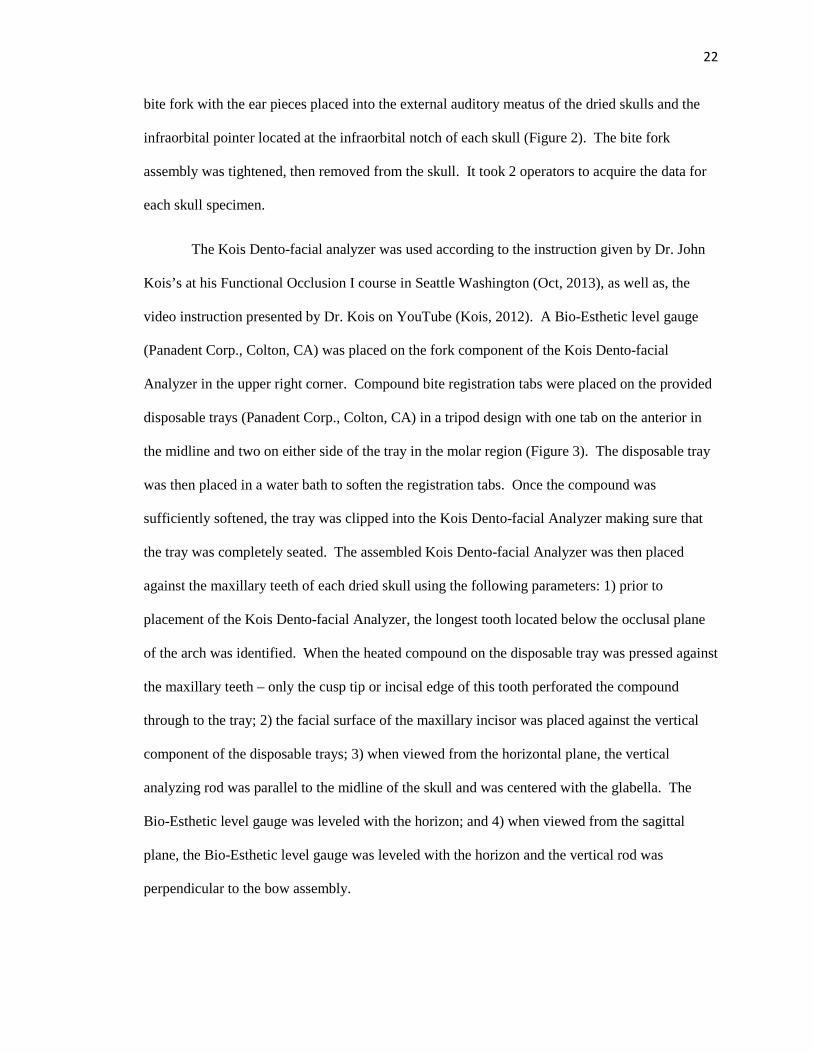
The Kois Dento-facial analyzer was used according to the instruction given by Dr. John
Kois’s at his Functional Occlusion I course in Seattle Washington (Oct, 2013), as well as, the
video instruction presented by Dr. Kois on YouTube (Kois, 2012). A Bio-Esthetic level gauge
(Panadent Corp., Colton, CA) was placed on the fork component of the Kois Dento-facial
Analyzer in the upper right corner. Compound bite registration tabs were placed on the provided
disposable trays (Panadent Corp., Colton, CA) in a tripod design with one tab on the anterior in
the midline and two on either side of the tray in the molar region (Figure 3). The disposable tray
was then placed in a water bath to soften the registration tabs. Once the compound was
sufficiently softened, the tray was clipped into the Kois Dento-facial Analyzer making sure that
the tray was completely seated. The assembled Kois Dento-facial Analyzer was then placed
against the maxillary teeth of each dried skull using the following parameters: 1) prior to
placement of the Kois Dento-facial Analyzer, the longest tooth located below the occlusal plane
of the arch was identified. When the heated compound on the disposable tray was pressed against
the maxillary teeth – only the cusp tip or incisal edge of this tooth perforated the compound
through to the tray; 2) the facial surface of the maxillary incisor was placed against the vertical
component of the disposable trays; 3) when viewed from the horizontal plane, the vertical
analyzing rod was parallel to the midline of the skull and was centered with the glabella. The
Bio-Esthetic level gauge was leveled with the horizon; and 4) when viewed from the sagittal
plane, the Bio-Esthetic level gauge was leveled with the horizon and the vertical rod was
perpendicular to the bow assembly.
23
Figure 2. Pana-Mount facebow on dried human skull.
Figure 3. Kois Dento-Facial Analyzer with compound tabs

24
After both facebows were recorded for each skull, a corresponding stone cast was
articulated on a PCH model Panadent articulator with the incisal pin set to 0. For the Pana-Mount
facebow, the following articulation method was used according to the instructions provided by
the manufacturer (Panadent Corp., Colton, CA) and by the video (Panadent, 2012). The Dyna-
Links and the incisal pin was removed from the upper member of the articulator. The facebow
was then attached to the upper member by clipping the ear holes of the facebow to the pins
located on the articulator arms and tightening the anterior screw on the facebow allowing anterior
portion of the upper member of the articulator to rest on the anterior surface of the facebow. The
entire assembly was stabilized by placing it on the lower member of the articulator prior to
completing the articulation procedure. The first maxillary cast for the corresponding skull was
then placed into the indentations made in the compound on the bite fork and a quick setting
Laboratory Plaster (Whip-Mix Corp., Louisville, KY) was then mixed with recommended
water/powder ratios in a Whip Mix Vacuum Power Mixer Plus (Whip Mix Corp., Louisville, KY)
for 30 seconds and used to attach the maxillary cast to the mounting assembly on the upper
member of the articulator.
For the Kois Dento-facial Analyzer, the following articulation method was used
according to the manufacturer’s instructions (Panadent Corp., Colton, CA) and the video
provided by Dr. Kois (Kois, 2012). The adjustable mounting platform was used with the index
set at zero. The disposable tray was removed from the Kois Dento-facial Analyzer and positioned
in the corresponding holes on the mounting platform. The platform was then placed on the
magnetic mounting plate on the lower member of the articulator. The second maxillary cast for
that corresponding skull was then placed into the indentations made in the compound on the
disposable plate and a quick setting mounting stone (Whip Mix Corp., Louisville, KY) was then
mixed with the proper water/powder ratio in a Whip Mix Vacuum Power Mixer Plus (Whip Mix
25
Corp., Louisville, KY) for 30 seconds and used to attach the maxillary cast to the mounting
assembly on the upper member of the articulator.
The mounting of the maxillary cast made by the Pana-Mount facebow was used for
comparison with the Kois Dento-facial analyzer articulated cast. The position of the Pana-Mount
facebow maxillary cast was indexed by fabrication of a remount jig in the following procedure.
A stone patty was created on a magnetic plate placed on the lower member of the articulator.
Once set, lab putty (Lab Putty Hard Silicone Material, Coltene/Whaledent, Altst�tten,
Switzerland) was hand mixed according to manufacturer’s instructions and placed in a horseshoe
shape on the stone patty. Prior to the polymerization of the lab putty, the mounted maxillary cast
from the Pana-Mount facebow was placed on the upper member of the articulator and the cusp
tips and incisal edges of this cast were indexed into the putty with the incisal pin set at 0. The
putty was allowed to polymerize and the maxillary cast was then removed from the remount jig.
This procedure was repeated for each cast articulated with the Pana-Mount facebow.
For recording the three-dimensional location of each cast at the articulator condyles, a
CPI-III (Panadent Corp., Colton, CA) was used according to the instructions provided by the
manufacturer (Panadent Corp., Colton CA) and with the following protocol: 1) graph paper was
placed on the corresponding graph supports on the upper member of the CPI-III; 2) the Pana-
Mount articulated cast was attached to the upper member and the remount jig was placed on the
lower member; 3) upper and lower members of the CPI-III were brought together by indexing the
maxillary cast in the remount jig and securing them together using rubber bands and by placing
the anterior pin against the incisal table (Figure 4); 4) the position of the Pana-Mount articulated
cast was recorded by placing blue graph paper between the markers and the graph paper. A mark
was made on each of the three graph supports; 5) the position of the articulated cast using the
Kois Dento-Facial Analyzer was placed in the remount jig and the same method was used to
make a red mark on the same graph paper on each of the three graph supports; and 6) measure the
26
distance between the marks made by the Pana-Mount facebow and the Kois Dento-facial analyzer
using the Optical Resolver (Panadent Corp., Colton, CA) was used to make measurements with a
scale of 1/10 mm. (Figure 5)
Figure 4. Articulated cast with remount jig on the CPI-III Device.

Figure 5. Example of graphical recording on CPI
In preparation for measuring and comparing the distances from the incisal edge position
to the condylar centers on the articulator, as well as, determine the occlusal plane angle,
photographs of each articulation were taken. Each articulation was placed o
with the floor. Using a camera (Nikon model D300S, Nikon Inc., Melville, NY) situated on a
tripod, images were made of each articulation. Position indices on the floor ensured that the
camera tripod and camera remained in the same pos
settings on the camera were kept the same for every photo. All photographs were made in one
setting. (Figures 6 and 7)
. Example of graphical recording on CPI-III Device
In preparation for measuring and comparing the distances from the incisal edge position
to the condylar centers on the articulator, as well as, determine the occlusal plane angle,
photographs of each articulation were taken. Each articulation was placed on a table top level
with the floor. Using a camera (Nikon model D300S, Nikon Inc., Melville, NY) situated on a
tripod, images were made of each articulation. Position indices on the floor ensured that the
remained in the same position for each photo. Furthermore, the
settings on the camera were kept the same for every photo. All photographs were made in one
27
In preparation for measuring and comparing the distances from the incisal edge position
to the condylar centers on the articulator, as well as, determine the occlusal plane angle,
n a table top level
with the floor. Using a camera (Nikon model D300S, Nikon Inc., Melville, NY) situated on a
tripod, images were made of each articulation. Position indices on the floor ensured that the
ition for each photo. Furthermore, the
settings on the camera were kept the same for every photo. All photographs were made in one
28
Figure 6. Photographed image of articulated cast using Kois Dento-facial Analyzer
Figure 7. Photographed image of articulated cast using Pana-Mount Facebow

29
Cephalometric radiographs were made of each skull (Figure 8) (Orthoceph OC200D,
Tuusula, Finland) and Dolphin software (Dolphin Imaging 11.0, Patterson Dental Supply Inc.,
Chatsworth, CA). Positioning rods were placed in the external auditory meatus of each skull and
the nasal bone was positioned against the glabella aligner. The skulls were supported until the
position of Frankfort horizontal was made parallel to the floor. Tin foil was placed on the incisal
edge position of the maxillary anterior tooth 8 or 9 as well as on the mesial buccal cusp tip of the
first or second molar. After exporting the images, the images were placed into PowerPoint
(Microsoft, Redmond, WA) and the magnification level was set to 180% (Figure 9).
Figure 8. Skull in Orthoceph machine.
30
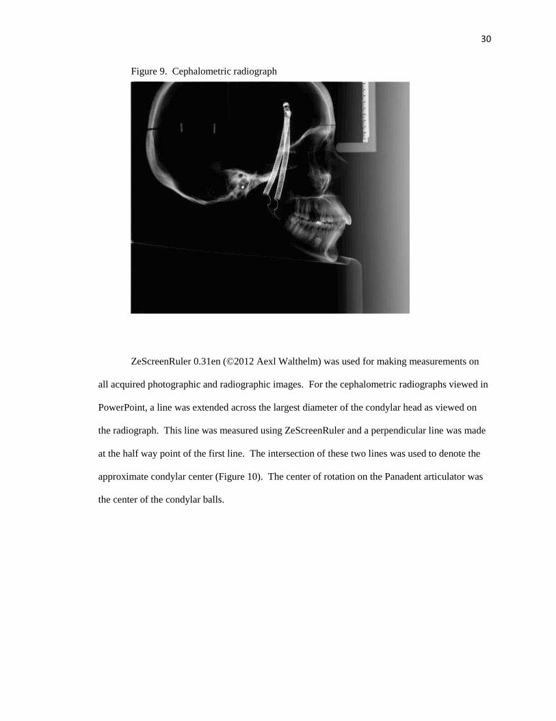
Figure 9. Cephalometric radiograph
ZeScreenRuler 0.31en (©2012 Aexl Walthelm) was used for making measurements on
all acquired photographic and radiographic images. For the cephalometric radiographs viewed in
PowerPoint, a line was extended across the largest diameter of the condylar head as viewed on
the radiograph. This line was measured using ZeScreenRuler and a perpendicular line was made
at the half way point of the first line. The intersection of these two lines was used to denote the
approximate condylar center (Figure 10). The center of rotation on the Panadent articulator was
the center of the condylar balls.

31
Figure 10. Enlarged view showing arbitrary axis location.
The axis of rotation was determined by measuring the distance between the approximate
condylar centers to the incisal edge of the maxillary anterior tooth. This was performed on each
photograph and radiograph. The occlusal plane angle was measured by extending a line from the
incisal edge of the central incisor and the mesiobuccal cusp tip of the first or second maxillary
molar. The angle of this line relative to the upper member of the articulator or Frankfort
Horizontal on the dried skulls was then measured.
Measuring the glabella aligner on the cephalometric x-ray machine and comparing that to
the dimension in the imported images determined the magnification on the lateral cephalometric
images. Measuring the Dyna-Link knob on the articulator and comparing that dimension to the
photographed image determined the magnification on the photographic images on the articulators.
One-way ANOVA and post hoc tests (Tukey-Kramer HSD) (α=.05) were used to evaluate
occlusal plane angle, axis-central incisor distance, and x. y, and z distance.

32
CHAPTER 4
RESULTS
Statistical analysis was completed for this study. A one-way ANOVA was used to test
the hypothesis that there will not be a difference in the distance between the maxillary central
incisors on articulated maxillary casts when using the Kois Dentofacial Analyzer or facebow
when compared with dry human skulls (Table 1). A test statistic of 6.26 (P=.0042) was obtained,
which indicates that at least two of the groups are significantly different. In order to determine
which groups differ with respect to this distance, a Least Square Means Differences Tukey’s HSD
post hoc analysis was performed. It was determined that the distance for the skull specimens was
significantly different from both the facebow and Kois Dentofacial Analyzer specimens (Table
2).
Table 1: One-way ANOVA for distance. Source DF Sum of Squares Mean Square F Ratio
Model 2 228.52844 114.264 6.26
Error 42 767.07467 18.264 Prob > F
C. Total 44 995.60311 .0042
Table 2: Least square means differences Tukey’s HSD. Levels not connected by same letter are
significantly different. Level Least Sq Mean
Facebow A 95.73
Kois A 95.51
Skull B 90.84
33
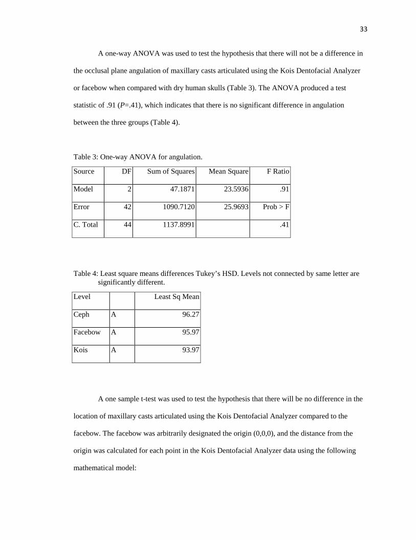
A one-way ANOVA was used to test the hypothesis that there will not be a difference in
the occlusal plane angulation of maxillary casts articulated using the Kois Dentofacial Analyzer
or facebow when compared with dry human skulls (Table 3). The ANOVA produced a test
statistic of .91 (P=.41), which indicates that there is no significant difference in angulation
between the three groups (Table 4).
Table 3: One-way ANOVA for angulation.
Source DF Sum of Squares Mean Square F Ratio
Model 2 47.1871 23.5936 .91
Error 42 1090.7120 25.9693 Prob > F
C. Total 44 1137.8991 .41
Table 4: Least square means differences Tukey’s HSD. Levels not connected by same letter are significantly different.
Level Least Sq Mean
Ceph A 96.27
Facebow A 95.97
Kois A 93.97
A one sample t-test was used to test the hypothesis that there will be no difference in the
location of maxillary casts articulated using the Kois Dentofacial Analyzer compared to the
facebow. The facebow was arbitrarily designated the origin (0,0,0), and the distance from the
origin was calculated for each point in the Kois Dentofacial Analyzer data using the following
mathematical model:
34
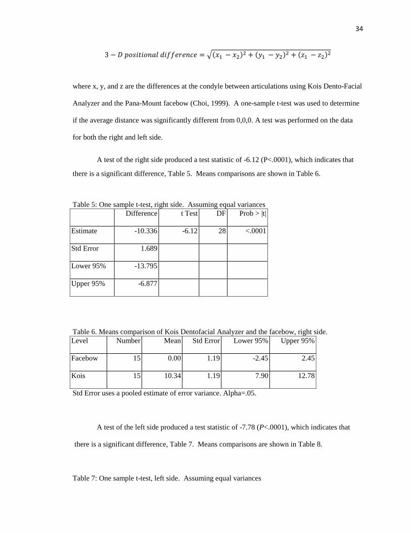
3 � � �������� �������� � ���� � ���� � ��� � ���� � ��� � ����
where x, y, and z are the differences at the condyle between articulations using Kois Dento-Facial
Analyzer and the Pana-Mount facebow (Choi, 1999). A one-sample t-test was used to determine
if the average distance was significantly different from 0,0,0. A test was performed on the data
for both the right and left side.
A test of the right side produced a test statistic of -6.12 (P<.0001), which indicates that
there is a significant difference, Table 5. Means comparisons are shown in Table 6.
Table 5: One sample t-test, right side. Assuming equal variances Difference t Test DF Prob > |t|
Estimate -10.336 -6.12 28 <.0001
Std Error 1.689
Lower 95% -13.795
Upper 95% -6.877
Table 6. Means comparison of Kois Dentofacial Analyzer and the facebow, right side. Level Number Mean Std Error Lower 95% Upper 95%
Facebow 15 0.00 1.19 -2.45 2.45
Kois 15 10.34 1.19 7.90 12.78
Std Error uses a pooled estimate of error variance. Alpha=.05.
A test of the left side produced a test statistic of -7.78 (P<.0001), which indicates that
there is a significant difference, Table 7. Means comparisons are shown in Table 8. Table 7: One sample t-test, left side. Assuming equal variances

35
Difference t Test DF Prob > |t|
Estimate -8.9520 -7.78 28 <.0001
Std Error 1.1512
Lower 95% -11.3100
Upper 95% -6.5940
Table 8. Means comparison of Kois Dentofacial Analyzer and the facebow, left side. Level Number Mean Std Error Lower 95% Upper 95%
Facebow 15 0.00 0.81399 -1.67 1.67
Kois 15 8.95 0.81399 7.29 10.62
Std Error uses a pooled estimate of error variance. Alpha=.05.
36
CHAPTER 5
DISCUSSION
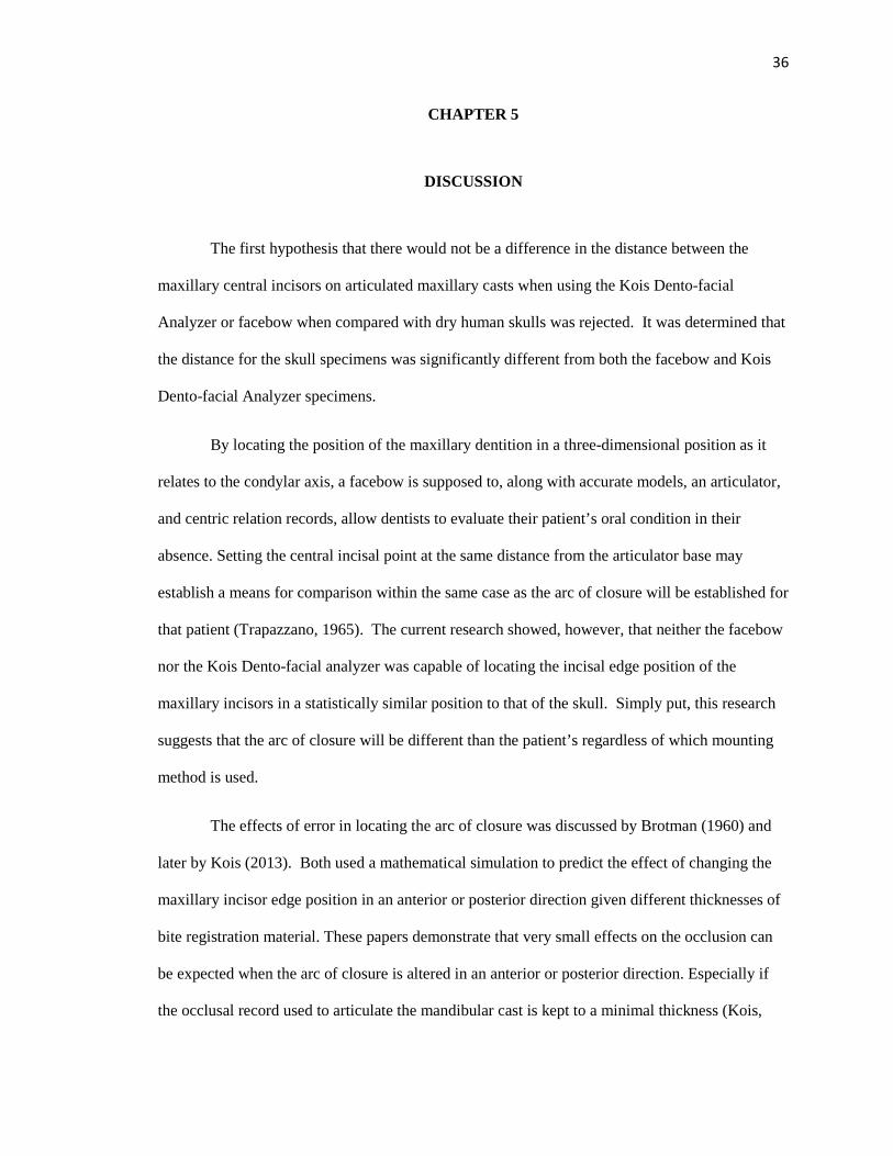
The first hypothesis that there would not be a difference in the distance between the
maxillary central incisors on articulated maxillary casts when using the Kois Dento-facial
Analyzer or facebow when compared with dry human skulls was rejected. It was determined that
the distance for the skull specimens was significantly different from both the facebow and Kois
Dento-facial Analyzer specimens.
By locating the position of the maxillary dentition in a three-dimensional position as it
relates to the condylar axis, a facebow is supposed to, along with accurate models, an articulator,
and centric relation records, allow dentists to evaluate their patient’s oral condition in their
absence. Setting the central incisal point at the same distance from the articulator base may
establish a means for comparison within the same case as the arc of closure will be established for
that patient (Trapazzano, 1965). The current research showed, however, that neither the facebow
nor the Kois Dento-facial analyzer was capable of locating the incisal edge position of the
maxillary incisors in a statistically similar position to that of the skull. Simply put, this research
suggests that the arc of closure will be different than the patient’s regardless of which mounting
method is used.
The effects of error in locating the arc of closure was discussed by Brotman (1960) and
later by Kois (2013). Both used a mathematical simulation to predict the effect of changing the
maxillary incisor edge position in an anterior or posterior direction given different thicknesses of
bite registration material. These papers demonstrate that very small effects on the occlusion can
be expected when the arc of closure is altered in an anterior or posterior direction. Especially if
the occlusal record used to articulate the mandibular cast is kept to a minimal thickness (Kois,
2013). With such small errors produced at the occlusal level,
using either system (Kois Dento
clinically. Although the difference in the incisal edge position might be significantly different
than that of the skull, it should not be extrapolated then that the amount of error produced at the
occlusal level would also be
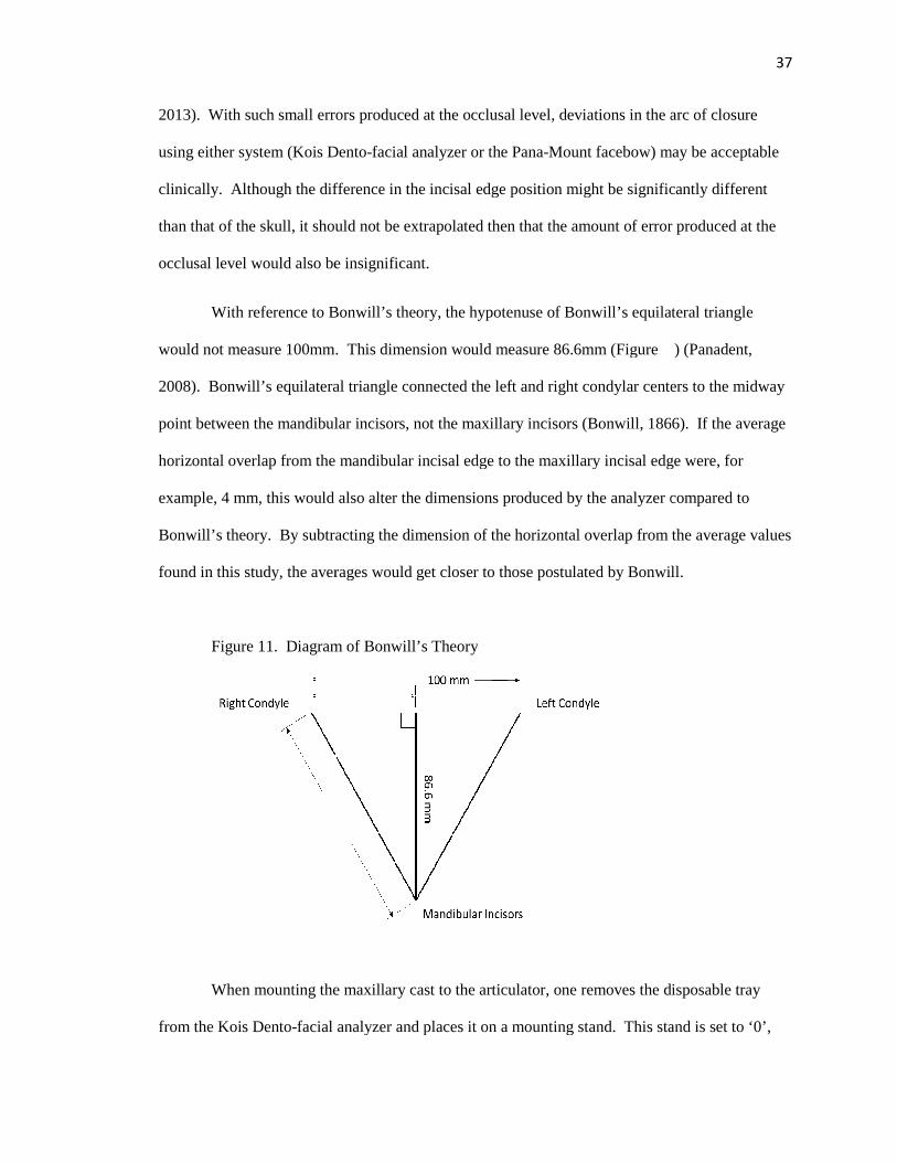
With reference to Bonwill’s theory, t
would not measure 100mm. This dimension would measure 86.6mm (Figure ) (Panadent,
2008). Bonwill’s equilateral triangle connected the left and right condylar centers to the midway
point between the mandibular incisors, not the maxillary incisors (Bonwill, 1866). If the average
horizontal overlap from the mandibular incisal edge to the maxillary incisal edge were, for
example, 4 mm, this would also alter the dimensions produced by the analyzer compared to
Bonwill’s theory. By subtracting
found in this study, the averages
Figure 11. Diagram of Bonwill’s Theory
When mounting the maxillary cast to the articulator, one removes the disposable tray
from the Kois Dento-facial analyzer and
2013). With such small errors produced at the occlusal level, deviations in the arc of closure
using either system (Kois Dento-facial analyzer or the Pana-Mount facebow) may be acceptable
e difference in the incisal edge position might be significantly different
than that of the skull, it should not be extrapolated then that the amount of error produced at the
occlusal level would also be insignificant.
With reference to Bonwill’s theory, the hypotenuse of Bonwill’s equilateral triangle
would not measure 100mm. This dimension would measure 86.6mm (Figure ) (Panadent,
2008). Bonwill’s equilateral triangle connected the left and right condylar centers to the midway
bular incisors, not the maxillary incisors (Bonwill, 1866). If the average
from the mandibular incisal edge to the maxillary incisal edge were, for
example, 4 mm, this would also alter the dimensions produced by the analyzer compared to
By subtracting the dimension of the horizontal overlap from the ave
found in this study, the averages would get closer to those postulated by Bonwill.
Diagram of Bonwill’s Theory
When mounting the maxillary cast to the articulator, one removes the disposable tray
facial analyzer and places it on a mounting stand. This stand is set to ‘0’,
37
deviations in the arc of closure
Mount facebow) may be acceptable
e difference in the incisal edge position might be significantly different
than that of the skull, it should not be extrapolated then that the amount of error produced at the
he hypotenuse of Bonwill’s equilateral triangle
would not measure 100mm. This dimension would measure 86.6mm (Figure ) (Panadent,
2008). Bonwill’s equilateral triangle connected the left and right condylar centers to the midway
bular incisors, not the maxillary incisors (Bonwill, 1866). If the average
from the mandibular incisal edge to the maxillary incisal edge were, for
example, 4 mm, this would also alter the dimensions produced by the analyzer compared to
the dimension of the horizontal overlap from the average values
Bonwill.
When mounting the maxillary cast to the articulator, one removes the disposable tray
places it on a mounting stand. This stand is set to ‘0’,
38
which places the maxillary cast in a position midway between the upper and lower members of
the articulator. From this position, the maxillary incisal edge is now supposed to be located 100
mm from a line perpendicular to the axis of rotation on the articulator. It is stated in the
instructions for the Kois-Dento-facial analyzer that this position is supported by multiple sources
including Bonwill, Monson’s spherical theory, Weinberg, and Dr. Kois’s original research
(Panadent, 2008). A description of the Kois Dento-Facial Analyzer is found on the Panadent
website (http://occlusion.files.wordpress.com/2014/03/instructions_for_kois_facial_analyzer.pdf).
The Kois Dento-facial Analyzer placed the maxillary incisal edge 95.51mm from the axis of the
articulator in this study. In comparison, the Pana-Mount facebow set the incisal edge
approximately 95.73mm away from the axis, a difference of only 0.22mm. The distance, as
measured from the cephalometric radiographs, was 90.84mm, or a difference of approximately
4mm from either facebow method. Other authors who also tried to determine the average axis
incisor distance found a similar measurement of 96.1mm (Stade, 1982). This is in comparison to
Kois’s average distance of 100.12mm (Kois, 2013).
Interestingly the Kois Dento-facial analyzer did not place the incisal edges exactly at
100mm as assumed. Some of the variation can be accounted for in the design of the disposable
tray used with the Kois system. As indicated in the instructions, the labial surface of the
maxillary incisor is placed against the vertical component of the tray. However, the angulation of
the incisors from the osseous structure of the maxilla influences the placement of the tray in
relation to the labial surfaces. Furthermore, indexing the incisors on the disposable tray in the
correct location was not as simple as it was implied to be. A certain amount of skill and training
in the placement of the Kois Dento-facial Analyzer was needed to be accurate.
One of the limitations of this study was that the actual kinematic axis of the dried skulls
could not be located. Thus, the measurement of the axis to incisal edge position was measured on
the cephalometric radiograph from an arbitrary center of the radiographed condyle (Gonzalez,
39
Kingery, 1968). In the orthodontic literature, the only source for a suggested location of the axis
is described by Ricketts (Ricketts, 1956). This position however is further down the condylar
neck than described by Bonwill’s method, and so this orthodontic landmark was not used.
Similarly, the axis location has been described as being 7 mm below Frankfort horizontal. The
method for locating the exact position however is unclear (Bergstrom, 1950) (Gonzalez, Kingery,
1968).
It is interesting to note that when the Pana-Mount facebow is attached to the upper
member of the articulator, the pins to which the facebow seat at the axis are approximately 7mm
posterior to the axis of rotation on the articulator. It seems that the manufacturers of the Panadent
system have taken into consideration some measurement simulating that the external auditory
meatus being posterior to the terminal hinge axis of the patient. This dimension may have been
applied based on the work by Teteruck and Lundeen in 1966 when they suggested modifying the
ear holes on the facebow in their study to a more posterior position. In that way, 75.5% of the
axis locations of the subjects in their study would fall within 6mm relative to an arbitrary axis
location (Teteruck, Lundeen, 1966). In comparison, other authors such as Schallhorn found 95%
of the axis points were located 13mm anterior to the posterior margin of the tragus on the tragus-
canthus line (Schallhorn, 1957). Regardless, as a result of the modification made by Panadent to
the location of the pins relative to the axis, the maxillary incisor distance to the axis has also been
modified once the facebow transfer is connected to the articulator base.
The second hypothesis that there would not be a difference in the occlusal plane
angulation of maxillary casts articulated using the Kois Dento-facial Analyzer or facebow when
compared with dry human skulls was accepted, as there is no significant difference in angulation
between the three groups.
Traditionally, discussions on the occlusal plane were in reference to denture construction
(Ogawa, 1996). According to Petricevic, the “most common reference plane is Frankfort

40
Horizontal which has been assumed to be horizontal when a patient is in an erect posture with
natural head position” (Petricevic 2006). The relationship of the occlusal plane to other
horizontal reference positions varies however between individuals. It has been hypothesized in
the literature that the occlusal plane is nearly parallel to Camper’s plane (Ogawa, 1996).
Comparatively, others found the occlusal plane varied from Camper’s plane by as much as 7
degrees and to Frankfort Horizontal by approximately 11 degrees (Olsson, 1961). Variations in
age, type of dentition, and posterior reference position change greatly and thus more detailed
comparisons between planes of reference may not be possible (Olsson, 1961).
While it is true that the Pana-mount facebow utilizes nasion as a third point to stabilize
the facebow while on the patient’s face, the developers of the Pana-Mount designed the arms of
the facebow to be 22mm below nasion and aligned with the infraorabital rim. Using the
dimension of nasion minus 23mm was advocated by Sicher in 1952 as an alternative to orbitale as
a third point of reference. The inferior surface of the frame becomes approximately level with
orbitale depending on the anatomical variation of the patient from this approximated dimension
(Sischer, 1952). When the Pana-Mount facebow is connected to the articulator, it was designed
to be aligned with the lower edge of the upper member of the articulator, making axis-orbital the
reference plane that is transferred from the patient to the articulator (Panadent, 2012).
While the facebow is reasonably accurate at transferring the vertical position of the
maxillary cast, using orbitale as a third point of reference does not transfer the esthetic reference
position to the articulator (Pitchford, 1991). The esthetic reference position according to
Pitchford is the position of the head when an individual is sitting or standing erect with the head
level and the eyes fixed on the horizon (Pitchford, 1991). “For 90% of the population, the
esthetic reference position is approximately 28 to 44mm below the condylar plane, yet a facebow
which uses orbitale as the third point of reference commonly places the incisal edges of the
maxillary teeth 54mm below the condylar plane” (Pitchford, 1991). The incisal edges are placed
41
too low, as orbitale is significantly higher than porion or the axis. More specifically, in the
esthetic reference position, Pitchford found that orbitale averaged 11.4mm above porion
(Pitchford, 1991). If axis is 7mm below porion as described by Bergstrom in 1950, than orbitale
would be almost 18.5mm higher than the axis. To correct these discrepancies, Pitchford
suggested raising either the orbital pointer of the orbital indicator by 18mm on a Whip mix
articulator and 11 mm on a Hanau (Pitchford, 1991). In contrast, Gonzalez and Kingery
suggested using a landmark 7mm inferior to orbitale to effectively transfer Frankfort Horizontal
Plane to the articulator (Gonzalez, Kingery, 1968).
Compared to traditional facebow systems, the Kois Dento-facial analyzer utilizes
unconventional reference positions to articulate the maxillary cast. Specifically, “this system (the
Kois Dento-facial Analyzer) registers the steepness and tilts of the occlusal plane related in three
planes of space” (Panadent, 2008). Unlike traditional facebows, anatomical landmarks are not
utilized. There is no physical third point of reference that should be identified on the patients face
such as orbitale or nasion, rather the operator must use the horizon and the identification of the
patient’s facial midline to orient the bow. Furthermore, one relies on the mounting platform to set
the antero-posterior dimension on the articulator.
In order to properly register the occlusal plane using the Kois Dento-facial analyzer the
proper technique must be applied. Rather than stabilizing the Kois Dento-facial analyzer against
the entire occlusal surfaces of the maxillary teeth, only the cusp tip/ incisal edge, which extends
beyond the occlusal level, should touch the platform. In this way, the cant of the occlusal plane
can be visualized once the disposable tray is seated on the mounting platform. It is interesting to
note that one of the advantages the Kois system is supposed to have over traditional techniques is
registering the occlusal plane in a position that can be optimally evaluated esthetically on the
articulator, as it is implied that this is a major disadvantage when using traditional earbow
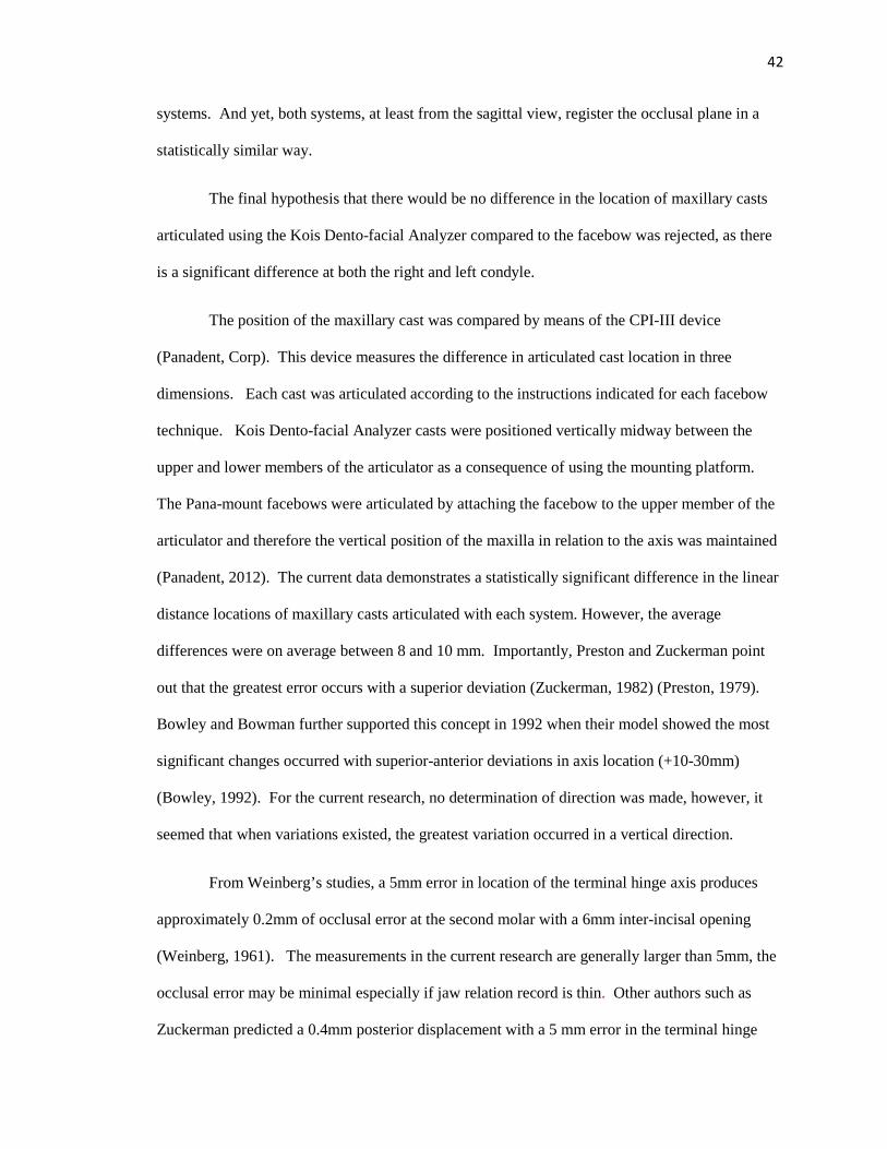
42
systems. And yet, both systems, at least from the sagittal view, register the occlusal plane in a
statistically similar way.
The final hypothesis that there would be no difference in the location of maxillary casts
articulated using the Kois Dento-facial Analyzer compared to the facebow was rejected, as there
is a significant difference at both the right and left condyle.
The position of the maxillary cast was compared by means of the CPI-III device
(Panadent, Corp). This device measures the difference in articulated cast location in three
dimensions. Each cast was articulated according to the instructions indicated for each facebow
technique. Kois Dento-facial Analyzer casts were positioned vertically midway between the
upper and lower members of the articulator as a consequence of using the mounting platform.
The Pana-mount facebows were articulated by attaching the facebow to the upper member of the
articulator and therefore the vertical position of the maxilla in relation to the axis was maintained
(Panadent, 2012). The current data demonstrates a statistically significant difference in the linear
distance locations of maxillary casts articulated with each system. However, the average
differences were on average between 8 and 10 mm. Importantly, Preston and Zuckerman point
out that the greatest error occurs with a superior deviation (Zuckerman, 1982) (Preston, 1979).
Bowley and Bowman further supported this concept in 1992 when their model showed the most
significant changes occurred with superior-anterior deviations in axis location (+10-30mm)
(Bowley, 1992). For the current research, no determination of direction was made, however, it
seemed that when variations existed, the greatest variation occurred in a vertical direction.
From Weinberg’s studies, a 5mm error in location of the terminal hinge axis produces
approximately 0.2mm of occlusal error at the second molar with a 6mm inter-incisal opening
(Weinberg, 1961). The measurements in the current research are generally larger than 5mm, the
occlusal error may be minimal especially if jaw relation record is thin. Other authors such as
Zuckerman predicted a 0.4mm posterior displacement with a 5 mm error in the terminal hinge

43
axis location and a 0.3mm anterior displacement with a -5mm terminal hinge axis deviation
(Zuckerman, 1982). From these statements, it is possible then that the difference in location of
the axis that occurs between the Pana-mount facebow and the Kois Dento-facial analyzer may
have a minimal effect on the occlusion. When other occlusal considerations are incorporated,
such as the use of anterior guidance, the effects of this difference in axis location may be smaller
still. Definitive conclusions on this cannot be made, however, until further research is conducted.
It is apparent that continued research on this topic is needed. Future research may
include application of the same protocol but applied to live human subjects rather than skulls. In
that way some of the inherent inaccuracies with using dried skulls may be eliminated.
Additionally, it is also suggested that a test of reproducibility of the Kois Dento-facial analyzer be
undertaken as it may be possible that achieving the same reference position is difficult with this
particular device.
44
CHAPTER 6
CONCLUSIONS
It is generally accepted that the use of a facebow, in the traditional sense, produces
articulated maxillary casts that are within clinically acceptable positions. It was unknown,
however, how this new facebow method (the Kois Dent-Facial Analyzer) would compare.
From this study, the following conclusions can be made:
1. The Kois Dento-Facial Analyzer mounts the maxillary casts in a position that is not
statistically different to the Pana-Mount facebow when comparing the incisal edge
position and the occlusal plane angle relative to Frankfort Horizontal.
2. Both the Kois Dento-Facial Analyzer and the Pana-Mount facebow locate the maxillary
incisal edge position in a significantly different position compared to the skull.
3. Both the Kois Dento-Facial Analyzer and the Pana-Mount facebow produce occlusal
plane angles that are not significantly different than the angle on the skull.
4. The three dimensional location of the maxillary cast varies approximately 8-10mm at the
condyles.

45
CHAPTER 7
APPENDIX A
Table 9. Raw Data. CPI III: Measuring the change in location of the maxillary cast articulated using the Kois Dento-facial Analyzer in three dimensions.
Right Left
Facebow 0.00 0.00
Facebow 0.00 0.00
Facebow 0.00 0.00
Facebow 0.00 0.00
Facebow 0.00 0.00
Facebow 0.00 0.00
Facebow 0.00 0.00
Facebow 0.00 0.00
Facebow 0.00 0.00
Facebow 0.00 0.00
Facebow 0.00 0.00
Facebow 0.00 0.00
Facebow 0.00 0.00
Facebow 0.00 0.00
Facebow 0.00 0.00
Kois 25.67 20.46
Kois 5.76 6.36
Kois 11.88 7.16
Kois 9.81 9.95
Kois 4.18 4.65
Kois 23.65 13.19
Kois 4.63 8.15
Kois 3.80 3.99
Kois 8.99 6.50
Kois 7.62 9.88
Kois 8.24 4.26
Kois 9.07 10.49
Kois 14.42 13.72
Kois 6.18 4.90
Kois 11.14 10.62

46
Table 11. Raw Data. Distance from the approximate condylar axis to the incisal edge position (mm).
Specimen Distance Specimen Distance Specimen Distance
Skull 87.7 Kois 96.2 Facebow 82.2
Skull 93.7 Kois 95.8 Facebow 100.7
Skull 83.1 Kois 95.8 Facebow 89.7
Skull 92.9 Kois 95.2 Facebow 96.6
Skull 91.1 Kois 95.5 Facebow 99.0
Skull 89.6 Kois 95.2 Facebow 96.2
Skull 89.1 Kois 94.6 Facebow 92.7
Skull 90.1 Kois 94.9 Facebow 94.5
Skull 96.3 Kois 95.8 Facebow 102.5
Skull 95.5 Kois 95.5 Facebow 103.2
Skull 89.5 Kois 95.6 Facebow 97.0
Skull 81.8 Kois 95.6 Facebow 87.2
Skull 93.9 Kois 95.1 Facebow 99.9
Skull 91.9 Kois 96.0 Facebow 93.0
Skull 96.4 Kois 95.8 Facebow 101.5
Table 12. Raw Data. Occlusal plane angle in degrees.
Specimen Angle Specimen Angle Specimen Angle
Ceph 103.6 Kois 92.8 Facebow 98.1
Ceph 93.6 Kois 89.5 Facebow 89.4
Ceph 95.2 Kois 92.9 Facebow 99.7
Ceph 97.2 Kois 98.9 Facebow 102.7
Ceph 97 Kois 97.3 Facebow 96.7
Ceph 102.1 Kois 95.5 Facebow 103.8
Ceph 94.2 Kois 100.5 Facebow 91.4
Ceph 86.9 Kois 89.7 Facebow 87.8
Ceph 98.1 Kois 98.1 Facebow 101.8
Ceph 98.5 Kois 91.5 Facebow 92.7
Ceph 103.3 Kois 95.3 Facebow 99.8
Ceph 84.8 Kois 93.5 Facebow 92.4
Ceph 103.8 Kois 94.3 Facebow 102.4
Ceph 90.3 Kois 91.4 Facebow 89.2
Ceph 95.5 Kois 88.3 Facebow 91.7

47
BIBLIOGRAPHY
Academy of Prosthodontics. (2005). The glossary of prosthodontic terms. J Prosth, 94(1), 10-92.
Balkwill, F. (1865-1867). The best form and arrangement of artificial teeth for mastication. Trans. Odontol. Soc. Gr. Brit., 5, 133-158.
Behrend, D. (1985). An esthetic control system for fixed and removable prosthodontics. J Prosth Dent, 54(4), 488-496.
Bellanti, N. (1973). The significance of articulator capabilities. Part 1. Adjustable vs. semi adjustable articulators. J Prosth Dent, 29(3), 269-275.
Bennett, N. (1908). A contribution to the study of the movements of the mandible. Proc. of Roy. Soc. of Med. Odontol. Sec.,1, 79-95.
Bergstrom, G. (1950). On the reproduction of dental articulation by means of articulators: a kinematic investigation. Acta Odont Scand, 9, 25.
Bonwill, W. (1899). The scientific articulator of human teeth as founded on geometrical mathematical and mechanical laws. Dental Items of Interest, (Oct), 617-643.
Bowley, J. (1992). Evaluation of variables associated with the transverse horizontal axis. J Prosth Dent, (68), 537-41.
Brandrup-Wognsen, T. (1953). The face-bow. Its significance and application. J Prosth Dent, 3(5), 618-630.
Brotman, D. (1960). Hinge axes. Part 1. The transverse hinge axis. J Prosth Dent, 10(3), 436-440.
Brotman, D. (1960). Hinge axes. Part 2. Geometric significance of transverse axis. J Prosth Dent, 10(4), 631-636.
Brotman, D. (1960). Hinge axes. Part 3. Vertical and sagittal rotational centers. J Prosth Dent, 10(5), 873-877.
Campion, G. (1905). Some graphic records of movements of the mandible in the living subject. Cosmos (Dental), 47, 39-42.
Chiche, G., & Aoshima, H. (1997). Functional verses aesthetic articulation of maxillary anterior restorations. PPAD, 9(3), 335-42.
Choi, D., Bowley, J., Marx, D., & Lee, S. (1999). Reliability of an ear-bow arbitrary face-bow transfer instrument. J Prosth Dent, 82(2), 150-6.
Clayton, J. (1971). Border positions and restoring occlusion. Dent Clin Nort Amer, (15), 525-42.

48
Craddock, F., & Symmons, H. (1952). Evaluation of the Facebow. J Prosth Dent, 2(5), 633-642.
Dos Santos Junior, J., Nelson, S., Nummikoski, P., (1996) Geometric analysis of occlusal plane orientation using simulated ear-rod facebow transfer system. J Prosth, 5(3), 172-81.
Ercoli, C., Graser, G., Tallents, R., & Galindo, D. (1999). Facebow record without a third point of reference: theoretical considerations and alternative techniques. J Prosth Dent, 82(2), 237-41.
Ferrario, V., Sforza, C., Tartaglia, G., Barbini, E., & Michielon, G. (1995). New television technique for natural head and body posture analysis. Cranio, 13(4), 247-55.
Ferrario, V., Sforza, C., Serrao, G., & Schmitz, J. (2002). Three-dimensional assessment of the reliability of a postural face-bow. J Prosth Dent, 87(2), 210-15.
Freeland, D., Kulbersh, R., & Kaczynski, R. (2010). Comparison of maxillary cast position mounted from true hinge kinematic face-bow vs. an arbitrary face-bow in three planes of space. RWISO Journal, (Sept), 45-54.
Gonzalez, H., & Kingery, R. (1968). Evaluation of planes of reference for orienting maxillary casts on articulators. JADA, 76(Feb), 329-337.
Goska, J., & Christensen, L. (1988). Comparison of cast positions by using four facebows. J Prosth Dent, 59(1), 42-4.
Hanau, R. (1926). Articulation defined, analyzed, and formulated. JADA, 13, 1694-1707.
Hobo, S., Shillingburg, H., &Whitsett, L. (1976). Articulator selection for restorative dentistry. J Prosth Dent, 36(1), 35-43.
Kois, J., Kois, D., & Chaiyabutr, Y. (2013). Occlusal errors generated at the maxillary incisal edge position related to discrepancies in the arbitrary horizontal axis location and to the thickness of the interocclusal record. J Prosth Dent, 110(5), 414-419.
Kois, J. (2012, 07 12). Introduction to the Kois Dento-facial analyzer system. Retrieved from http://www.youtube.com/watch?v=98WPDkB4ZCQ
Krueger, G., & Schneider, R. (1986). A plane of orientation with an extracranial anterior point of reference. J Prosth Dent, 56(1), 56-60.
Kurth, L., & Feinstein, I. (1951). The hinge axis of the mandible. J Prosth Dent, 1(3), 327-332.
Lauritzen, A., & Bodner, G. (1961). Variations in locations of arbitrary and true hinge axis. J Prosth Dent, 11(2), 224-229.

49
Lauritzen, A., & Wolford, L. (1961). Hinge axis location on an experimental basis. J Prosth Dent, 11(6), 1059-1067.
Lee, R. (1969). Jaw movements engraved in solid plastic for articulator controls. Part 1. Recording apparatus. J Prosth Dent, 22(2), 209-24.
Lee, R. (1969). Jaw movements engraved in solid plastic for articulator controls. Part 2. Transfer apparatus. J Prosth Dent, 22(5), 513-527.
Luce, C. (1889). Movements of the lower jaw. Bost. Med. Surg. Journ., 121, 8-11.
Lundeen, H., & Wirth, C. (1973). Condylar movement patterns engraved in plastic blocks. J Prosth Dent, 30(6), 866-75.
Lundeen, H., Shyrock, E., & Gibbs, C. (1978). An evaluation of mandibular border movements: their character and significance. J Prosth Dent, 40(4), 442-452.
Moberg, C. (1973). The pantograph as a facebow transfer instrument. J Prosth Dent, 29, 139-145.
Morneburg, T., & Proschel, P. (2002). Predicted incidence of occlusal errors in centric closing around arbitrary axes. Int J Prosth, 15(4), 358-364.
Morneburg, T., & Proschel, P. (2011). Impact of arbitrary and mean transfer of dental casts to the articulator on centric occlusal errors. Clin Oral Investig, 15(3), 427-34.
Nagy, W., Smithy, T., &Wirth, C. (2002). Accuracy of a predetermined transverse horizontal mandibular axis point. J Prosth Dent, 87(4), 387-94.
Ogawa, T., Koyano, K., & Suetsugu, T. (1996). The relationship between inclination of the occlusal plane and jaw closing path. J Prosth Dent, 76(6), 576-580.
Olsson, A., & Posselt, U. (1961). Relationship of various skull reference lines. J Prosth Dent, 11(6), 1045-1049.
Panadent. (2008, 10 13). Kois Dento-facial analyzer system instructions: “a simplified facebow for esthetics and function". Retrieved from http://occlusion.files.wordpress.com/2014/03/instructions_for_kois_facial_analyzer.pdf.
Panadent. (2012, 04 09). Relationship of facebow to articulator. Retrieved from http://www.youtube.com/watch?v=KLGdYIEUj2I
Panadent, (2003). Dento-facial analyzer. US Patent 6582931 B1. Retrieved from http://www.google.com/patents/US6582931.
Petricevic, N., Celebic, A., Celic, R., & Baucic-Bozic, M. (2006). Natural head position and inclination of cranial planes. Int J Prosth, 19(3), 279-80.

50
Pitchford, J. (1991). A re-evaluation of the axis orbitale plane and the use of orbitale in a facebow transfer record. J Prosth Dent, 66, 349-55.
Posselt, U. (1952). Studies in the mobility of the human mandible. Acta Odont. Scandinav, 10, 1-160.
Preston, J. (1979). A reassessment of the mandibular transverse horizontal long axis theory. J Prosth Dent, 41(6), 605-13.
Proschel, P., Maul, T., & Morneburg, T. (2000). Predicted incidence of excursive occlusal errors in common modes of articulator adjustment. Int J Prosth, 13(4), 303-310.
Prothero, J. (1923). Prosthetic dentistry. (3rd ed., pp. 1077-1176). Chicago: Medico-Dental Publishing Co.
Ricketts, R. (1956). The role of cephalometrics in prosthodontics. J Prosth Dent, 6(4), 488-503.
Sadr, K., & Sadr, M. (2009). A study of parallelism of the occlusal plane and ala tragus line. J Dent Res Dent Clin Dent Prospects, 3(4), 107-9.
Schallhorn, R. (1957). A study of the arbitrary center and the kinematic center of rotation for facebow mountings. J Prosth Dent, 7(2), 162-169.
Schlosser, R. (1946). Complete denture prosthesis. (2nd ed., p. 205). Philadelphia and London: WB Saunders Co.
Schulte, J. (1984). The hinge axis transfer procedure: A 3d error analysis. J Prosth Dent, 51(2), 247-251.
Schuyler, C. (1953). Factors of occlusion applicable to restorative dentistry. J Prosth Dent, 3(6), 772-82.
Seifert, D. et.al, (2000). Relations of reference planes for orientation of the prosthetic plane. Acta Stomatol Croat, 34(4), 413-16.
Sicher, H. (1952). Oral anatomy. (2 ed., p. 91). St. Louis: The C.V. Mosby Co.
Sicher, H. (1956). The biologic significance of hinge axis determination. J Prosth Dent, 6, 616.
Simpson, J., Hesby, R., Pfeifer, D., &Pelleu, G. (1984). Arbitrary mandibular hinge axis locations. J Prosth Dent, 51(6), 819-822.
Sloan, R. (1952). Recording and transferring the mandibular axis. J Prosth Dent, 2, 172.
Stade, E., Hanson, J., & Baker, C. (1982). Esthetic considerations in the use of face-bows. J Prosth Dent, 48(3), 253-256.
Stansbery, C. (1928). Futility of the facebow. JADA, 15, 1467-71.

51
Starcke, E. (2000). Dental instrumentation. The history of articulators: the appearance and early history of facebows. J Prosth Dent, 9(3), 161-5.
Starcke, E. (2001). Dental Instrumentation. The History of articulators: From facebows to the Gnathograph, a brief history of early devices developed for recording condylar movement: Part 1. J Prosth Dent, 10(4), 241-248.
Starcke E. (2002). Dental Instrumentation. The history of articulators: A critical history of articulators based on geometric theories of mandibular movement: Part 1. J Prosth Dent, 11(2): 134-146.
Strohaver, R., & Ryan, J. (1988). New facebow simplifies routine use and dental laboratory cooperation. J Prosth Dent, 60(5), 638-41.
Teteruck, W., & Lundeen, H. (1966). Accuracy of an ear face-bow. J Prosth Dent, 16(6), 1039-1046.
Trapozzano, V. (1965). Complete dentures - laws of articulation. J Prosth Dent, 13(1), 34-44.
Walker, P. (1980). Discrepancies between arbitrary and true hinge axes. J Prosth Dent, 43, 279.
Walker, W. (1896). Prosthetic dentistry: glenoid fossa; movements of the mandible; cusps and teeth. Dent. Cosmos, 38, 34-43.
Weinberg, L. (1959). The occlusal plane and cuspal inclination relation to incisal-condylar guidance for protrusive excursions. J Prosth Dent, 9(4), 607-618.
Weinberg, L. (1959). The transverse hinge axis: real or imaginary. J Prosth Dent, 9, 775-787.
Weinberg, L. (1961). An evaluation of the face bow mounting. J Prosth Dent, 11, 32.
Weinberg, L. (1963). An evaluation of basic articulators and their concepts. Part 1. Basic concepts. J Prosth Dent, 13(4), 622-644.
Weinberg, L. (1963). An evaluation of basic articulators and their concepts. Part 2. Arbitrary, positional, semi adjustable articulators. J Prosth Dent, 13(4), 645-663.
Wilkie, N. (1979). The anterior point of reference. J Prosth Dent, 41, 488.
Zuckerman, G. (1982). The geometry of the arbitrary hinge axis as it relates to the occlusion. J Prosth Dent, 48, 725-733.
Zuckerman, G (1985). Practical considerations for using the face-bow for complete denture prosthodontics. J Prosth Dent, 53, 2, 219-221.

52