a composite electrode of tio2 nanotubes and nanoparticles synthesised by hydrothermal treatment for...
TRANSCRIPT

Cite this: RSC Advances, 2013, 3,11001
A composite electrode of TiO2 nanotubes andnanoparticles synthesised by hydrothermal treatmentfor use in dye-sensitized solar cells
Received 28th December 2012,Accepted 24th April 2013
DOI: 10.1039/c3ra23482g
www.rsc.org/advances
Xiaoyan Wang,a Lidong Sun,a Sam Zhang,*a Xiu Wang,b Kaifu Huo,c Jijiang Fu,c
Hairong Wangc and Dongliang Zhaod
In dye-sensitized solar cells, highly ordered TiO2 nanotube arrays provide superior electron transport.
However, their low surface area limits the amount of dye loading and thus the photocurrent. In the
present work, a hydrothermal treatment of the TiO2 nanotubes was carried out to form TiO2 nanoparticles
on the tube walls, thereby increasing the surface area for a higher amount of dye loading. The nanotube
arrays were prepared by electrochemical anodization and subsequently hydrothermally treated in water at
90 uC. Using the same nanotube length (i.e., 6.5 mm), but different treatment durations, it was found that
nanotubes under hydrothermal treatment for 45 min yielded the best photovoltaic performance, due to
the combined merits of a high surface area and vectorial electron transport. Under the same treatment
duration (i.e., 45 min), but using different nanotube lengths, nanoparticle formation was found to be
accelerated in the longer tubes. The parts of the tubes near the bottom were constantly filled with
nanoparticles, which limited cell efficiency to about 2.2% when the length was over 16.5 mm. Accordingly,
a further efficiency enhancement of up to 3.5% was achieved with tubes of 16.5 mm by adjusting the
duration of the hydrothermal treatment.
1 Introduction
Since 1991,1 dye-sensitized solar cells (DSSCs) have receivedworldwide attention as a promising and competitive candidatefor low-cost photovoltaics.2–4 Conventional DSSCs adopt TiO2
nanoparticles (about 15–30 nm) as the photoanodes. Thephotoanodes provide a very high surface area for dyeadsorption and hence give rise to a high photocurrent,however numerous joints between the particles deterioratethe electron transport process.3 As such, one-dimensionalnanostructures (e.g., nanowires,5,6 nanotubes,7,8 and nanor-ods9) have been widely studied as alternatives for efficientelectron transport. Of particular interest are TiO2 nanotubearrays fabricated using electrochemical anodization, whichyields an oriented alignment suitable for vectorial electrontransport. However, in contrast to nanoparticles, the tubesexhibit a lower surface area for dye adsorption, which in turnresults in a lower photocurrent and efficiency. Consequently,
the most efficient device based on nanotubes yields anefficiency of y8% in comparison to y12% for nanoparticles,as detailed in one recent review paper.10
Much effort has been made to increase the surface area ofthe nanotubes, e.g., by exploiting the parallel configurationbased on double-sided nanotubes,11 decreasing the tubediameter,12,13 growing bamboo-type tubes,14 creating hierarch-ical structure,15,16 decorating nanoparticles,15,17,18 and so on.A composite electrode of TiO2 nanotubes and nanoparticles isfavorable for efficient DSSCs, as it combines the merits of theindividual components, i.e., the high surface area of thenanoparticles and the vectorial electron transport of thenanotubes. Several methods have been exploited to producethe composite electrode. TiCl4 treatment has been widelyemployed to precipitate very small nanoparticles (y3 nm17,19)on tube walls before assembling solar cells. To form a desiredcomposite electrode, a concentrated solution is needed,17,19,20
otherwise no obvious changes can be observed after thetreatment.20 Recently, hydrothermal treatment has beenreported to form the composite electrode in (NH4)2TiF6
16 ora P25-nanoparticle-containing aqueous solution.15 Watersoaking is another facile method used to convert nanotubeseither partially or entirely into nanoparticles or nano-wires.18,21,22 This process is performed without any additionalchemicals at room temperature, but it takes a very long periodof time (2–3 days) to form the composite architecture. In all
aSchool of Mechanical and Aerospace Engineering, Nanyang Technological
University, 50 Nanyang Avenue, Singapore 639798, Singapore.
E-mail: [email protected]; Fax: +65 67924062; Tel: +65 67904400bSchool of Materials Science and Engineering, Nanyang Technological University, 50
Nanyang Avenue, Singapore 639798, SingaporecSchool of Materials and Metallurgy, Wuhan University of Science and Technology,
Wuhan 430081, P. R. ChinadCentral Iron and Steel Research Institute, No. 76 Xueyuan Nanlu, Beijing 100081, P.
R. China
RSC Advances
PAPER
This journal is � The Royal Society of Chemistry 2013 RSC Adv., 2013, 3, 11001–11006 | 11001
Publ
ishe
d on
25
Apr
il 20
13. D
ownl
oade
d by
Uni
vers
ity o
f M
isso
uri a
t Col
umbi
a on
15/
08/2
013
11:4
2:12
.
View Article OnlineView Journal | View Issue

these cases, the obtained structures yield a high surface areafor dye loading and hence give rise to an appreciable efficiencyenhancement when applied in DSSCs. Nevertheless, the outertube walls are unlikely to be used any more, as the intertubespaces are filled or blocked by the newly formed nanoparticles.Additionally, electron transport in these electrodes is deterio-rated, as the integrity of the tubes has already been destroyed.In view of these problems, it is necessary to figure out theformation process of the composites in order to tailor theconfiguration for further efficiency improvement.
In this study, composite electrodes of nanotubes andnanoparticles were prepared by hydrothermal treatment ofthe nanotubes in water at 90 uC for short periods (,5 h). Thecomposites were systematically investigated and applied indye-sensitized solar cells by either changing the treatmentduration or tube length. The results indicate that, with anoptimized treatment duration for a particular tube length, anoptimal composite structure can be produced to utilize boththe inner and outer tube walls while maintaining the tubefeatures, thus increasing the power conversion efficiency.
2 Experimental
2.1 Anodization and hydrothermal treatment
Highly ordered TiO2 nanotube arrays were fabricated byelectrochemical anodization using titanium foil (0.25 mm,99.5% purity, Alfa Aesar) as the working electrode (back sideunprotected23) and a platinum gauze as the counter electrode.Prior to the anodization, the foils were degreased in acetone,ethanol and deionized (DI) water for 20 min each and driedusing a stream of air. The distance between electrodes was setat 22 mm. The electrolyte solution was ethylene glycol (extrapure, Merck) containing 0.3 wt% ammonium fluoride (98+%reagent, Sigma-Aldrich) and 5 vol% DI water. All of theanodizations were conducted at 50 V and at room temperature(y20 uC).
The resultant nanotubes were ultrasonically cleaned inethanol/DI water (1 : 1, v/v) for 30 min to remove thenanowires accumulated on tube tops.20 Prior to ultrasonica-tion, the as-anodized nanotubes were annealed at 200 uC for 2h to increase the adhesion strength between the tubes and thetitanium substrate. Subsequently, the cleaned and top-openednanotubes were immersed in 20 mL DI water inside a Teflon-lined stainless steel autoclave for the hydrothermal treatment.The autoclave was kept in an oven at 90 uC for differentdurations (,5 h). After cooling down to room temperature inthe oven, the samples were rinsed with DI water and dried inair.
2.2 Solar cell assembly
To obtain fully crystallized TiO2 nanotube arrays for use in DSSCdevices, the pristine and hydrothermally treated nanotubes weresubjected to thermal annealing at 450 uC for 3 h in air.Thereafter, the nanotubes were sensitized by soaking in a 0.3mM solution of N719 dye (cis-diisothiocyanato-bis(2,20-bipyridyl-4,40-dicarboxylato)ruthenium(II)bis(tetrabutylammonium), Solaronix)in acetonitrile/tert-butanol (1 : 1, v/v) solvent for 48 h. The
sensitized nanotube arrays were assembled into DSSCs withplatinized FTO glasses acting as the counter electrode,which were prepared by the thermal decomposition of aH2PtCl6 solution (0.6 mM) at 400 uC for 15 min. The twoelectrodes were separated using hot-melt films (SX1170,Solaronix, Switzerland) with a thickness of 25 mm. Theelectrolyte (EL HPE, Dyesol) containing an iodide/tri-iodideredox couple was introduced from one hole on the counterelectrode under a partial vacuum. The active area of the cellswas 0.26 cm2.
2.3 Characterizations
Top and cross-sectional views of the nanotube arrays werecharacterized by field emission scanning electron microscope(FESEM, JEOL, JSM-7600F). The morphology and structure of asingle tube attached with nanoparticles were obtained bytransmission electron microscopy (TEM, JEOL, JEM- 2010, 200kV). The phase compositions were examined with glancingangle X-ray diffraction (GAXRD, PANalytical Empyrean, Cu-Karadiation).
The photocurrent–voltage characteristics of DSSCs weremeasured with a digital source meter (Keithley 2400) undersimulated AM 1.5 illumination (100 mW cm22) from a solarsimulator (1 kW xenon with AM 1.5 filter, Muller). The amountof dye loading for the nanotube films was determined bymeasuring the UV-vis absorption spectra of the desorbed dyesolutions. The dye molecules were desorbed by immersing thesensitized samples in a 0.1 M solution of NaOH in a mixedsolvent system (water/ethanol = 1 : 1, v/v).
3 Results and discussion
3.1 Synthesis of the composite electrodes by hydrothermaltreatment
Fig. 1(a, b) shows the pristine smooth TiO2 nanotubes withpore diameter of 92 ¡ 5 nm. The top-opened tubes areobtained after clearing away the undesired nanowires from thetube tops.20 Compared with conventional nanoparticles usedin DSSCs, the large diameter tubes provide a much lowersurface area for dye adsorption. In order to increase the
Fig. 1 FESEM images of the top (a, c, e) and cross-section (b, d, f) of the TiO2
nanotube arrays of 6.5 mm, without (a, b) and with hydrothermal treatment for30 min (c, d) and 45 min (e, f).
11002 | RSC Adv., 2013, 3, 11001–11006 This journal is � The Royal Society of Chemistry 2013
Paper RSC Advances
Publ
ishe
d on
25
Apr
il 20
13. D
ownl
oade
d by
Uni
vers
ity o
f M
isso
uri a
t Col
umbi
a on
15/
08/2
013
11:4
2:12
. View Article Online
surface area, the nanotubes were therefore subjected tohydrothermal treatment in water at 90 uC.
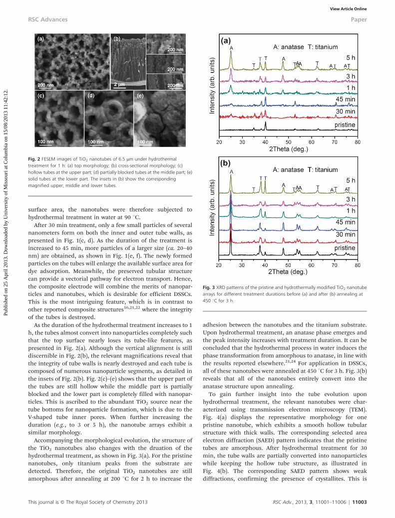
After 30 min treatment, only a few small particles of severalnanometers form on both the inner and outer tube walls, aspresented in Fig. 1(c, d). As the duration of the treatment isincreased to 45 min, more particles of a larger size (ca. 20–40nm) are obtained, as shown in Fig. 1(e, f). The newly formedparticles on the tubes will enlarge the available surface area fordye adsorption. Meanwhile, the preserved tubular structurecan provide a vectorial pathway for electron transport. Hence,the composite electrode will combine the merits of nanopar-ticles and nanotubes, which is desirable for efficient DSSCs.This is the most intriguing feature, which is in contrast toother reported composite structures16,21,22 where the integrityof the tubes is destroyed.
As the duration of the hydrothermal treatment increases to 1h, the tubes almost convert into nanoparticles completely suchthat the top surface nearly loses its tube-like features, aspresented in Fig. 2(a). Although the vertical alignment is stilldiscernible in Fig. 2(b), the relevant magnifications reveal thatthe integrity of tube walls is nearly destroyed and each tube iscomposed of numerous nanoparticle segments, as detailed inthe insets of Fig. 2(b). Fig. 2(c)–(e) shows that the upper part ofthe tubes are still hollow while the middle part is partiallyblocked and the lower part is completely filled with nanopar-ticles. This is ascribed to the abundant TiO2 source near thetube bottoms for nanoparticle formation, which is due to theV-shaped tube inner pores. When further increasing theduration (e.g., to 3 or 5 h), the nanotube arrays exhibit asimilar morphology.
Accompanying the morphological evolution, the structure ofthe TiO2 nanotubes also changes with the druation of thehydrothermal treatment, as shown in Fig. 3(a). For the pristinenanotubes, only titanium peaks from the substrate aredetected. Therefore, the original TiO2 nanotubes are stillamorphous after annealing at 200 uC for 2 h to increase the
adhesion between the nanotubes and the titanium substrate.Upon hydrothermal treatment, an anatase phase emerges andthe peak intensity increases with treatment duration. It can beconcluded that the hydrothermal process in water induces thephase transformation from amorphous to anatase, in line withthe results reported elsewhere.21,24 For application in DSSCs,all of these nanotubes were annealed at 450 uC for 3 h. Fig. 3(b)reveals that all of the nanotubes entirely convert into theanatase structure upon annealing.
To gain further insight into the tube evolution uponhydrothermal treatment, the relevant nanotubes were char-acterized using transmission electron microscopy (TEM).Fig. 4(a) displays the representative morphology for onepristine nanotube, which exhibits a smooth hollow tubularstructure with thick walls. The corresponding selected areaelectron diffraction (SAED) pattern indicates that the pristinetubes are amorphous. After hydrothermal treatment for 30min, the tube walls are partially converted into nanoparticleswhile keeping the hollow tube structure, as illustrated inFig. 4(b). The corresponding SAED pattern shows weakdiffractions, confirming the presence of crystallites. This is
Fig. 2 FESEM images of TiO2 nanotubes of 6.5 mm under hydrothermaltreatment for 1 h: (a) top morphology; (b) cross-sectional morphology; (c)hollow tubes at the upper part; (d) partially blocked tubes at the middle part; (e)solid tubes at the lower part. The insets in (b) show the correspondingmagnified upper, middle and lower tubes.
Fig. 3 XRD patterns of the pristine and hydrothermally modified TiO2 nanotubearrays for different treatment durations before (a) and after (b) annealing at450 uC for 3 h.
This journal is � The Royal Society of Chemistry 2013 RSC Adv., 2013, 3, 11001–11006 | 11003
RSC Advances Paper
Publ
ishe
d on
25
Apr
il 20
13. D
ownl
oade
d by
Uni
vers
ity o
f M
isso
uri a
t Col
umbi
a on
15/
08/2
013
11:4
2:12
. View Article Online

consistent with the pertinent XRD patterns shown in Fig. 3(a).When further prolonging the duration of the treatment to 45min, the original tubular structure is still discernible with thetube being filled with big particles, as shown in Fig. 4(c), andmore crystallites are thus formed (see the relevant inset). After1 h, the tubes are transformed into nanoparticles completely,losing the tubular structure, as depicted in Fig. 4(d). Thecorresponding SAED pattern shows the typical features seenfrom nanocrystals. The TEM results are in fairly goodagreement with the morphology and phase evolutions thatare presented in Fig. 1–3.
Hydrothermal generation of TiO2 nanoparticles is based ona dissolution–precipitation process in which water moleculesplay an essential role.21,24,25 The as-anodized TiO2 nanotubesare amorphous and thermodynamically unstable in water.Water molecules adsorb onto the surface of the amorphoustitania to combine with the basic octahedral titania unit ofTiO6
22. Subsequently, the dehydration of water leads to aregular arrangement of the octahedral unit and crystallization.Noticeably, stably crystallized tubes barely induce the dissolu-tion–precipitation process, resulting in limited changes to thetube morphology and structure.22 In this process, the ambienttemperature and pressure affect the nucleation and growth ofthe crystallites, influencing the final electrode configuration.Under the current experimental conditions, i.e., hydrothermaltreatment at 90 uC, the size and amount of the nanoparticlesincrease with treatment duration. For short durations (below 1h), amorphous tube walls partially dissolve and precipitate toform crystalline nanoparticles on the tubes. For long durations(above 1 h), the whole tube converts into a columnar structureconsisting of nanoparticles and no discernible morphologychange is observed for further prolonged treatment.Meanwhile, the relevant crystallinity enhances with thetreatment duration, as can be seen from the increasedintensity of the XRD (Fig. 3(a)) and SAED patterns (Fig. 4). It
demonstrates that the morphological evolution and phasetransformation occur simultaneously during the dissolutionand precipitation process. As compared to previousreports,18,21 the hydrothermal treatment at elevated tempera-ture (i.e., 90 uC) in this study drastically shortens thetransformation time (i.e., y1 h vs. 2–3 days). Furthermore,the nanoparticle size is much larger than that formed at roomtemperature (i.e., 20–40 nm vs. 3–10 nm 21) because the highertemperature and pressure facilitate the particle growth.
3.2 Application of the composite electrodes in DSSCs
The pristine and hydrothermally treated TiO2 nanotubes weresubsequently exploited as photoanodes in DSSCs. The photo-current–voltage characteristics are shown in Fig. 5(a).Compared to solar cells based on pristine nanotubes, thosebased on the treated nanotubes exhibit a higher powerconversion efficiency. The efficiency as a function of hydro-thermal treatment duration is summarized in the inset ofFig. 5(a). It shows that the efficiency dramatically increasesfrom 1.04% to 2.04% and then slightly drops to 1.63% as theduration increases. The enhancement in efficiency can be
Fig. 4 TEM images of a single pristine TiO2 nanotube (a), and nanotubes afterhydrothermal treatment for 30 min (b), 45 min (c), and 1 h (d). The insets are thecorresponding selected area electron diffraction patterns.
Fig. 5 Photocurrent–voltage characteristics of DSSCs based on pristine andhydrothermally treated TiO2 nanotube arrays of 6.5 mm (a) and thecorresponding dye loading study (b). The inset shows the efficiency as a functionof the hydrothermal treatment duration.
11004 | RSC Adv., 2013, 3, 11001–11006 This journal is � The Royal Society of Chemistry 2013
Paper RSC Advances
Publ
ishe
d on
25
Apr
il 20
13. D
ownl
oade
d by
Uni
vers
ity o
f M
isso
uri a
t Col
umbi
a on
15/
08/2
013
11:4
2:12
. View Article Online
ascribed to the nanoparticle formation under hydrothermaltreatment, which enhances the dye adsorption properties.Fig. 5(b) shows the relevant dye loading study. From 30 min to45 min, the remarkable increase in the amount of dye loadingcontributes to the abrupt efficiency enhancement, which inturn originates from the enlarged surface area from formingbig nanoparticles (see Fig. 1 and 4). Further increase in thetreatment duration has little influence on the dye amount, asthe tubes convert into nanoparticles completely around 1 h(see Fig. 2 and 4). In addition, the filled tube bottoms andintertube spacing after long treatment durations (see Fig. 2)reduce the surface area for dye adsorption, thus lowering thephotocurrent and power conversion efficiency. Moreover, thedestroyed integrity of the nanotubes may deteriorate thecharge collection process and therefore affect the cellperformance, as shown from the decreased photocurrent withincreased treatment duration (from 45 min to 5 h in Fig. 5(a))under a similar amount of dye loading (see Fig. 5(b)). Adetailed study of the electron transport and recombination inthese composite nanostructures is currently under way.Eventually, the nanotubes under hydrothermal treatment for45 min exhibit the highest efficiency in the present study,since they combine the advantages of nanoparticles andnanotubes.
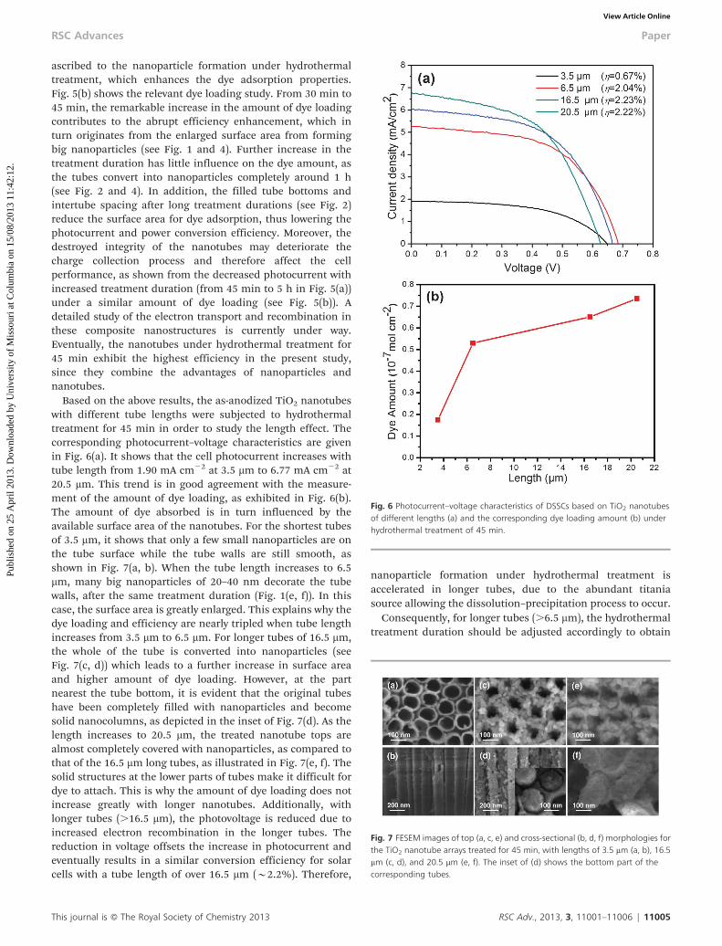
Based on the above results, the as-anodized TiO2 nanotubeswith different tube lengths were subjected to hydrothermaltreatment for 45 min in order to study the length effect. Thecorresponding photocurrent–voltage characteristics are givenin Fig. 6(a). It shows that the cell photocurrent increases withtube length from 1.90 mA cm22 at 3.5 mm to 6.77 mA cm22 at20.5 mm. This trend is in good agreement with the measure-ment of the amount of dye loading, as exhibited in Fig. 6(b).The amount of dye absorbed is in turn influenced by theavailable surface area of the nanotubes. For the shortest tubesof 3.5 mm, it shows that only a few small nanoparticles are onthe tube surface while the tube walls are still smooth, asshown in Fig. 7(a, b). When the tube length increases to 6.5mm, many big nanoparticles of 20–40 nm decorate the tubewalls, after the same treatment duration (Fig. 1(e, f)). In thiscase, the surface area is greatly enlarged. This explains why thedye loading and efficiency are nearly tripled when tube lengthincreases from 3.5 mm to 6.5 mm. For longer tubes of 16.5 mm,the whole of the tube is converted into nanoparticles (seeFig. 7(c, d)) which leads to a further increase in surface areaand higher amount of dye loading. However, at the partnearest the tube bottom, it is evident that the original tubeshave been completely filled with nanoparticles and becomesolid nanocolumns, as depicted in the inset of Fig. 7(d). As thelength increases to 20.5 mm, the treated nanotube tops arealmost completely covered with nanoparticles, as compared tothat of the 16.5 mm long tubes, as illustrated in Fig. 7(e, f). Thesolid structures at the lower parts of tubes make it difficult fordye to attach. This is why the amount of dye loading does notincrease greatly with longer nanotubes. Additionally, withlonger tubes (.16.5 mm), the photovoltage is reduced due toincreased electron recombination in the longer tubes. Thereduction in voltage offsets the increase in photocurrent andeventually results in a similar conversion efficiency for solarcells with a tube length of over 16.5 mm (y2.2%). Therefore,
nanoparticle formation under hydrothermal treatment isaccelerated in longer tubes, due to the abundant titaniasource allowing the dissolution–precipitation process to occur.
Consequently, for longer tubes (.6.5 mm), the hydrothermaltreatment duration should be adjusted accordingly to obtain
Fig. 6 Photocurrent–voltage characteristics of DSSCs based on TiO2 nanotubesof different lengths (a) and the corresponding dye loading amount (b) underhydrothermal treatment of 45 min.
Fig. 7 FESEM images of top (a, c, e) and cross-sectional (b, d, f) morphologies forthe TiO2 nanotube arrays treated for 45 min, with lengths of 3.5 mm (a, b), 16.5mm (c, d), and 20.5 mm (e, f). The inset of (d) shows the bottom part of thecorresponding tubes.
This journal is � The Royal Society of Chemistry 2013 RSC Adv., 2013, 3, 11001–11006 | 11005
RSC Advances Paper
Publ
ishe
d on
25
Apr
il 20
13. D
ownl
oade
d by
Uni
vers
ity o
f M
isso
uri a
t Col
umbi
a on
15/
08/2
013
11:4
2:12
. View Article Online

the preferred composite electrode of nanotubes and nanopar-ticles. This has been proved in Fig. 8, where nanotubes of 16.5mm in length were treated for less than 45 min. Thephotovoltaic device exhibits the best performance when thetreatment duration is reduced to around 15 min. All thecharacteristics are improved when compared to the deviceswith tubes treated for 45 min (photocurrent: 8.82 vs. 6.04 mAcm22, photovoltage: 0.70 vs. 0.67 V, fill factor: 0.57 vs. 0.55).Eventually, a power conversion efficiency of 3.54% is achieved.Therefore, an optimal treatment duration exists for aparticular tube length. For long tubes, the treatment durationshould be shortened to obtain an optimized compositestructure, which makes full use of both outer and inner tubewalls while also conserving the tube features.
4 Conclusions
It is facile and effective to create TiO2 nanoparticles on anodicnanotubes using a hydrothermal treatment in water. The tubemorphology and structure evolve with the duration of thehydrothermal treatment. For tubes with a length of 6.5 mm,within 1 h titania nanoparticles form on both the inner andouter tube walls while keeping the integrity of the tubes. Atprolonged times exceeding 1 h, the nanotubes are entirelyconverted into nanoparticles. At 45 min, the best efficiency of2.04% is obtained due to the combined effect of a high surfacearea from the nanoparticles and the vectorial electrontransport from the still preserved nanotubes. For tubes ofdifferent lengths under the same treatment duration (i.e., 45min), the efficiency of solar cells increases with tube length upto 16.5 mm, but this stays nearly constant over 16.5 mm. This isowing to the accelerated nanoparticle formation in longertubes, which fill the lower parts of the tubes and hence reducethe available surface area for dye attachment. Accordingly, afurther efficiency enhancement of 3.54% is achieved using
nanotubes of 16.5 mm by shortening the treatment duration toonly 15 min.
Acknowledgements
We thank Yong Mei Yoke of the Materials Lab of School ofMechanical and Aerospace Engineering, NanyangTechnological University, for her assistance in TEM measure-ments. This work is also supported by CISRI grant: 11020990A.
References
1 B. O’Regan and M. Gratzel, Nature, 1991, 353, 737–740.2 M. Gratzel, J. Photochem. Photobiol., C, 2003, 4, 145–153.3 M. Gratzel, Inorg. Chem., 2005, 44, 6841–6851.4 M. Gratzel, Nature, 2001, 414, 338–344.5 M. Law, L. E. Greene, J. C. Johnson, R. Saykally and P.
D. Yang, Nat. Mater., 2005, 4, 455–459.6 J. B. Baxter and E. S. Aydil, Appl. Phys. Lett., 2005, 86, 1–3.7 G. K. Mor, K. Shankar, M. Paulose, O. K. Varghese and C.
A. Grimes, Nano Lett., 2006, 6, 215–218.8 K. Zhu, N. R. Neale, A. Miedaner and A. J. Frank, Nano Lett.,
2007, 7, 69–74.9 J. Jiu, S. Isoda, F. Wang and M. Adachi, J. Phys. Chem. B,
2006, 110, 2087–2092.10 L. Sun, S. Zhang, Q. Wang and D. Zhao, Nanosci.
Nanotechnol. Lett., 2012, 4, 471–482.11 L. Sun, S. Zhang, X. Wang, X. W. Sun, D. Y. Ong and A. K.
K. Kyaw, Energy Environ. Sci., 2011, 4, 2240–2248.12 X. Wang, S. Zhang and L. Sun, Thin Solid Films, 2011, 519,
4694–4698.13 N. Liu, K. Lee and P. Schmuki, Electrochem. Commun., 2012,
15, 1–4.14 D. Kim, A. Ghicov, S. P. Albu and P. Schmuki, J. Am. Chem.
Soc., 2008, 130, 16454–16455.15 A. Hu, C. Cheng, X. Li, J. Jiang, R. Ding, J. Zhu, F. Wu, J. Liu
and X. Huang, Nanoscale Res. Lett., 2011, 6, 91–96.16 M. D. Ye, X. K. Xin, C. J. Lin and Z. Q. Lin, Nano Lett., 2011,
11, 3214–3220.17 P. Roy, D. Kim, I. Paramasivam and P. Schmuki,
Electrochem. Commun., 2009, 11, 1001–1004.18 J. Lin, X. L. Liu, M. Guo, W. Lu, G. G. Zhang, L. M. Zhou, X.
F. Chen and H. T. Huang, Nanoscale, 2012, 4, 5148–5153.19 D. Kim, P. Roy, K. Lee and P. Schmuki, Electrochem.
Commun., 2010, 12, 574–578.20 L. Sun, S. Zhang, X. Wang, X. W. Sun, D. Y. Ong, X. Wang
and D. Zhao, ChemPhysChem, 2011, 12, 3634–3641.21 D. Wang, L. Liu, F. Zhang, K. Tao, E. Pippel and K. Domen,
Nano Lett., 2011, 11, 3649–3655.22 N. Liu, S. P. Albu, K. Lee, S. So and P. Schmuki, Electrochim.
Acta, 2012, 82, 98–102.23 L. Sun, S. Zhang, X. W. Sun, X. Wang and Y. Cai, Langmuir,
2010, 26, 18424–18429.24 Y. Liao, W. Que, P. Zhong, J. Zhang and Y. He, ACS Appl.
Mater. Interfaces, 2011, 3, 2800–2804.25 J. Yu, G. Dai and B. Cheng, J. Phys. Chem. C, 2010, 114,
19378–19385.
Fig. 8 Photocurrent–voltage characteristics of DSSCs based on pristine andhydrothermally treated TiO2 nanotube arrays of 16.5 mm in length usingdifferent treatment durations.
11006 | RSC Adv., 2013, 3, 11001–11006 This journal is � The Royal Society of Chemistry 2013
Paper RSC Advances
Publ
ishe
d on
25
Apr
il 20
13. D
ownl
oade
d by
Uni
vers
ity o
f M
isso
uri a
t Col
umbi
a on
15/
08/2
013
11:4
2:12
. View Article Online