a consideration of p-delta effects in ductile …3)0151.pdf · 151 a consideration of p-delta...
TRANSCRIPT
151
A C O N S I D E R A T I O N OF P - D E L T A E F F E C T S
IN D U C T I L E R E I N F O R C E D C O N C R E T E F R A M E S
T. Paulay*
ABSTRACT
The likely effects of secondary moments due to the gravity load, which is being laterally displaced during inelastic seismic storey drift, upon ductile reinforced concrete frames is examined. Existing building code recommendations and design procedures relevant to the phenomenon are briefly reviewed. The probable effect of P-delta moments on inelastic dynamic frame response is discussed. With the aid of illustrations various design considerations are presented. It is suggested that if strength demand due to P-delta effects exceeds 1 5 % of the ideal lateral load carrying capacity of a subframe, this strength demand should be m e t . From the comparison of the elastic and inelastic deformations of a frame due to earthquake loading, recommendations are made for the estimation of critical inelastic drifts in the lower half of the frame. This is subsequently used to quantify the problem with the aid of the "stability index". The quantitative evaluation of P-delta effects for an 18 storey frame is illustrated in the appendix.
1. INTRODUCTION
Recent work of a discussion group of the New Zealand National Society for Earthquake Engineering, Committees of the Standards Association of New Zealand and researchers at Universities was centered on various design aspects of earthquake resisting ductile reinforced concrete frames. In this context the implications of the so called P-delta effects, widely considered to be relatively unimportant in seismic design, remained unresolved. In the common linear elastic "first order" analysis P-delta effects are neglected. Whenever secondary effects due to structural deformations, such as delta, are also included in the elastic analysis, it is no longer linear and reference is made to a "second order" analysis.
After briefly reviewing current practice and restating well established principles of the P-delta phenomenon with reference to seismic design only, an attempt is made to formulate a simple design procedure. A number of questions lead up to the design recommendations:
(a) A r e secondary moments due to P-delta effects critical in seismic design, and if so, when are they critical? (b) Is the remedy to be found in increased lateral stiffness or in added strength to compensate for loss in lateral load carrying capacity and in energy dissipation.
2. A REVIEW OF CURRENT APPROACHES TO THE P-DELTA PROBLEM
Most building codes do not give definitive guidance with respect to the quantifying of P-delta effects. The SEAOC Code is a typical document .. It requires that "lateral deflections or drift of a storey*
* Professor of Civil Engineering, University of Canterbury, Christchurch.
# In N e w Zealand the word "floor"would be used.
relative to its adjacent storeys shall be considered in accordance with accepted engineering practice". In its commentary this document implies that only secondary m e m b e r s , which are not part of the lateral force resisting system, must be checked for actions that might be induced in them by interstorey drift. In this the drift should be arbitrarily assumed to be four times that calculated for the response of the elastic structure to code forces.
The most recent relevant recommendations of the Applied Technology C o u n c i l ( 2 ) concern themselves also with limitations on storey drifts. Presumably no additional requirements need be met if the computed interstorey drift, 6, is less than a certain limit, typically 1% to 1.5% of the storey height. The drift is derived from the expression
6 = » (1 - 8) ( 1 )
where 6 e is the drift computed for the elastic frame under code specified lateral loading, y is the ductility factor, typically equal to 5 for ductile reinforced concrete frames, and 8 is a stability coefficient which is similar to the stability index subsequently given in Eq. ( 4 b ) . In Eq. (1) the elastic drift is magnified by the factor 1/(1 - 8 ) , to allow for the additional drift due to P-delta secondary m o m e n t s .
The New Zealand Code for the Design of Steel S t r u c t u r e s ' ^ makes it a very clear and distinct requirement t h a t , "if in any frame the P-delta moment resulting from the product of an ultimate column load ( P ) , excluding loads resulting from resisting overturning, and the interstorey deflection at first yield at a level (delta) exceeds 5 percent of the plastic moment capacity of the beams framing into the column at that level, then the strength of the frame shall be increased to carry the P-delta m o m e n t s " .
This provision concedes a 20 percent
B U L L E T I N O F T H E N E W Z E A L A N D N A T I O N A L S O C I E T Y F O R E A R T H Q U A K E E N G I N E E R I N G , V O L . 1 1 , N O . 3 , S E P T E M B E R , 1 9 7 8 .

152
loss of beam capacity with respect to lateral loading when a storey displacement ductility ratio of four is attained. The intention of this provision is to make a progressive failure due to P-delta effects, to be examined subsequently in greater detail, unlikely. It is not clear whether the first yield refers to the frame as a whole or to the storey in question. It appears that if the required increase of the plastic moment capacity of the beams as a result of the computed elastic drift 6 e is considerably m o r e than 5 percent, the capacity loss in the beams so designed, due to P-delta moment, at a displacement ductility of four, may be larger than 20 percent.
(4) In a recent study Andrews pointed
out that in focussing on the role of compression m e m b e r s , codes tend to divert designers * attention from the significance that P-delta effects have on beams of ductile frames. In an analytical study he suggested that with proper flexibility control the influence of P-delta effects will always be negligible. He concluded that existing design controls(5) for seismic zone A of New Zealand are adequate to limit P-delta effects to tolerable levels. From design judgement this level was considered to be maintained if the energy loss of the work done by the storey earthquake shear in the absence of gravity load (P) was not reduced by more than 10 percent by the P-delta effect. He suggested that the existing drift limit of 1% of storey height should, however, be reduced to 0.8% and 0.6% in seismic zones B and C respectively.
In reporting the experimental results related to the behaviour of subassemblages of reinforced concrete ductile frames, Bertero and Popov pointed out the seriousness of the compounding effects of stiffness and strength degradation due to inelastic reversed cyclic loading, and that of P-delta m o m e n t s . In their model they found 4 0 % loss of storey shear capacity caused by P-delta moments at a displacement ductility ratio of four, and they concluded that this cannot be neglected in either analysis or design, as it may lead to premature instability. They also found experimentally that a large portion of the inelastic interstorey drift was due to the breakdown of anchorage in the beam-column joints, resulting in excessive slippage of the flexural reinforcement. It must be pointed o u t , however, that the dramatic loss of strength (40%) associated in their specimen with a displacement ductility factor of 4, corresponded with a large drift of 5 percent of the storey height. They concluded that the consideration of P-delta effects should b e included in the design of m e d i u m high-rise b u i l d i n g s , and in particular storey drift limits should be established by limiting the displacement ductility ratios that may be used in the design.
In a section dealing with slenderness effects on compression m e m b e r s , the 1977 edition of the ACI Building Code and its c o m m e n t a r y ^ ) points out that for the critical compression load in frames not braced against sidesway the sum of all column loads, Z P U , rather than individual column loads P u , should be considered. T h e design column moments are then
appropriately magnified. In order to ensure that the magnified column end-moments can be sustained at beam-column joints, the beams must also be designed to resist these magnified moments. Because the transition from a braced to an unbraced frame cannot be defined clearly, the document suggests that whenever the stability index Q a is less than 0.04 the P-delta moment is not expected to exceed 5 percent of the first order m o m e n t s , and therefore the frame can be considered to be braced. The stability index defined in this c o d e ( 7 ) is
where H u is the total factored lateral force acting within the storey, such as due to wind, and 6 e is the elastically-computed first order interstorey deflection due to H u . The commentary of this code mentions that procedures for evaluating frame stiffness are currently being developed for special application to structures in seismic areas and that they should be considered as they become available. These comments imply that in the future the ACI Building Code m i g h t extend its moment magnification procedure also to compensate for P-delta effects in unbraced frames that are subjected to seismic actions.
There are also other techniques that can efficiently evaluate the effect of storey sway on column strength. Apart from a second-order finite element a n a l y s i s , direct and iterative P-delta analyses have been developed. The latter are relatively simple. They aim to determine storey by storey the interstorey drift 6 e . Those analyses and consequent design procedures are reviewed in an excellent paper by MacGregor and Hage . They conclude that in the range of 0. 0475<Q a< 0.22 sufficiently accurate column moments are obtained if the second-order moments are calculated directly from the first order deflections. The significance of foundation deformation in the estimation of <5e is emphasised. For values of the stability index, Q a , larger than 0.2 the probability of column failure increases rapidly and it is suggested that such frames should not be used.
The major problem in any stability or second-order analysis of concrete structure is the choice of a suitable mathematical model of flexural rigidity EI under various loading conditions. The difficulty w i l l be appreciated if the contributions of cracking, axial load, inelastic behaviour of steel and concrete, cyclic reversed loading, and the variation of the cracked regions along a member upon flexural stiffnesses are considered. For purposes of second-order analysis a reasonable estimate of flexural rigidity may be m a d e ( 1 2 ) if I = 0.4 I g for beams and 0.8 Ig for columns.
In all these stability analyses the intensities of both the gravity load (P) and the lateral load (H u) are known. The structure is expected to resist these forces close to the state of elastic limit and hence a reasonable estimate of the
153
drift 6 e can be made for the design (ultimate) load. In none of the known second-order design procedures is the effect of displacement ductility considered.
Some indication of the magnitude of interstorey drifts and associated P-delta effects that may be expected during catastrophic earthquakes in ductile frames, which were designed in accordance with recent p r o p o s a l s ' ^ ) , m a v ^ e gained from an analytical study of J u r y ( 9 ) . The maximum percentage loss of ideal storey moment capacity due to P-delta effects in various frames, subjected to specially chosen ground excitations of only limited duration, is presented in Table 1. in terms of R where
P-Delta Moment Demand for the R _ Critical Storey
Available Total Ideal Beam Moment Capacity at Floor
x 100
It is seen that the El Centro 1940 N-S excitation, often used as a prototype, did not produce critical conditions in the 6 and 18 storey frames studied. Drifts, of the magnitude imposed during tests by Bertero and P o p o v w e r e not encountered in this analytical study. It is pointed o u t , however, that the analysis did not include allowances for stiffness degradation due to repeated and significant excursions beyond yield.
3. THE STABILITY INDEX
The distorted shape of a multistorey frame at an instant of severe inelastic lateral displacement is shown in Fig. 1. Plastic hinges that have developed are also shown. W h i l e the maximum displacement at roof level is A u , the centre of gravitational attraction on the mass at the same time is displaced only by A m . The secondary moment due to P-delta effect with respect to the ground floor is therefore W-t-Am, where W t is the total weight of the frame. This overturning m o m e n t will need to be resisted by moments and particularly by axial forces at the base of the columns, as indicated in Fig. 1, w h i c h are additional to those required to equilibrate gravity and lateral loads. It is evident that these actions, when applied to plastic hinges, will reduce the member capacities that will be available to resist lateral forces generated by earthquake m o t i o n s . The axial forces, induced in the columns due to P-delta moments only, originate from shear forces generated in beams at each floor. The beams at a floor in turn are affected by the product of the gravity load at that floor and from the frame above and the storey drift.
A somewhat idealised configuration of the beams and columns at intermediate storeys of the frame of Fig. 1 are shown in Fig. 2 ( a ) . The relative displacement of the floors, i.e. the drift, is 6. Consequently the secondary moment W t r 6 i + W t r S 2 ~ w t r ^ must be resisted by the subframe, drawn with heavy lines in Fig. 2 ( a ) .
In accordance with accepted principles used in N e w Zealand, the chosen structural system consists of "strong" columns and "weak" b e a m s . Therefore the strength of a subframe w i t h respect to overturning moments of any kind is limited by the strength of the beams rather than that of the columns. If the ideal terminal flexural capacity of a
beam, shown as a plastic hinge, is , then at the development of a beam sway mechanism, shown in Fig. 2 ( c ) , the ideal moment capacity of the subframe is ZM^. Consequently the total lateral earthquake load carrying capacity of the subframe is
EM = EM. e I w. 6 tr (3)
These terminal m o m e n t s , which are introduced to the beams by the column shear forces, such as shown in Fig. 2 ( a ) , need be compared with the total dependable moment demand stipulated in the design^ ' for the sub-frame, Z M e . The significance of the secondary m o m e n t , W t r 6 , in reducing the lateral load resisting capacity of the subframe at the floor under consideration, is conveniently measured by its ratio to the required dependable design moment demand thus:
w r ZM (4a)
The storey drift can be expressed in terms of the average slope of the frame, (Fig. 1) A u / H , the average of the storey heights above and below the floor under consideration, l c , and a suitable displacement magnification factor. A, which relates the storey drift to the average slope of the frame. With these substitutions Eq. (4a) becomes
1 W. A c tr u HEM (4b)
where is termed the stability index.
It is suggested that in view of the inaccuracies in estimates involved in the design process for seismic actions and the conservatism in estimating an appropriate value for A, P-delta effects need not be considered when Q r is smaller than 0.15. This limit is approximately three times larger than what has been suggested for wind l o a d ^ 1 2 ' .
4. THE PROBABLE INFLUENCE OF P-DELTA EFFECTS ON THE DYNAMIC RESPONSE
The response of a well designed and detailed subframe of the type shown in Fig. 2(a) to cyclic earthquake simulating static loading may be represented by curve 1 in Fig. 3. If the secondary moment contribution due to P-delta effects is significant, the resistance of the subframe against lateral load can be markedly reduced during the first loading path. This is shown by curve 2 in Fig. 3. The shaded area also indicates the resulting loss of energy dissipation in the first quadrant of a full cycle of loading. However, it is also evident that w h e n the subframe is being returned to its original (undisplaced) position, the resistance against external lateral load is being increased by the 6 W t r secondary m o m e n t s . Consequently during the complete cycle of loading, shown in Fig. 3, there will be no loss of energy dissipation due to P-delta m o m e n t s . This indicates that the P-delta effect should have no significant effect upon the inelastic dynamic response of a ductile frame as long as the displacement amplitudes in both directions are of similar m a g n i t u d e s .
In a study of the influence of design

154
assumptions on the computed dynamic response of ductile frames to 5 different ground m o t i o n s , Powell and R o w ( 1 0 ) found only small increases of displacements and interstorey drifts when P-delta effects were considered. The 10 storey frames studied were relatively flexible. However, the chosen ground motions imposed a maximum interstorey drift of only 1.2% of the storey height.
Using an entirely different approach, Andrews has s h o w n ( 4 ) that the P-delta elastic softening effect on the increase of the fundamental period T of a frame, designed according to NZS 4203, is negligible and hence it does not justify a reduction in the design base shear.
Fig. 3 shows that the secondary moments reduce both strength and stiffness during the first quadrant of the response, whereas increased resistance is offered against forces that tend to restore the frame to its original perfectly vertical position. It is thus evident that after a very large displacement in one direction, resulting from a long velocity p u l s e , the frame may not b e restored to its original undisplaced position. During subsequent ground excitations the frame will exhibit degrading strength characteristics in the loading direction and this could encourage "crawling", leading to incremental collapse, as illustrated in Fig. 4. This type of response is more likely to occur in structures in w h i c h energy dissipation is concentrated in a storey so that inherently large storey drifts are required to provide the necessary system displacement ductility. The critical nature of the P-delta effect on frames w i t h column hinge mechanisms is evident from studies recently carried out by Kelly U 1 ) .
In most reinforced concrete structures some stiffness degradation, as a result of several large displacement excursions into the inelastic domain, will be inevitable.
Bauschinger effect on the flexural bars in the plastic hinge zones, shear displacements in the same regions and slip of the beam bars in beam-column joint c o r e s , will be responsible in frames for some stiffness reduction, particularly at the onset of load application in each new cycle of imposed displacement. The response of a subframe to monotonic and cyclic loading with equal amplitudes in both directions at an advanced stage of stiffness deterioration are shown by curves 1 and 2 in Fig. 5. The contribution of P-delta moments to the cyclic response of the degrading stiffness model is shown by the curves enclosing the shaded area. W h e n Figs. 4 and 5 are compared it is immediately apparent that much smaller resistance is being offered by this latter structure w h e n it is being returned to its original (undisplaced) position. It is seen that, for the same drift, the loss of energy dissipation due to stiffness degradation can be very considerable. However, a beneficial feature of the response, in comparison with that shown in Fig. 4, is the reduction of resistance against restoration of the frame to its original configuration. It appears that progressive stiffness degradation, w h i c h may lead to increased displacement
response for a given ground excitation, is not likely to aggrevate further incremental failure due to P-delta effects.
5. DESIGN CONSIDERATIONS
The obvious precaution to be taken in an attempt to minimise detrimental P-delta effects, is to increase the stiffness of the f r a m e d ) . However, it is difficult to properly quantify the critical deflections, i.e. drift. A routine calculation procedure will yield the deflections at each floor when the lateral static load is defined and an elastic analysis is used. Unfortunately the critical effects of P-delta moments emerge only w h e n large inelastic deflections occur. These inelastic deformations are much more difficult to estimate.
If P-delta effects are likely to be critical in an earthquake resisting frame, a radical increase in stiffness will be required to alleviate these effects. A moderate increase in beam and column sizes, without being accompanied by strength increase, is not likely to reduce the inelastic interstorey drifts drastically. For example, in the study of frames by Powell and Row(10) it was found that a 2.8 fold increase in beam stiffnesses and some consequent increase in strength reduced the total displacement and drift by approximately 4 0 % only. Such large increases in beam stiffnesses from one design to another will rarely be possible in practical frames. Moreover, increased stiffness will invite increased force response and h e n c e , to comply with code requirements (5) .
the strength of the members throughout the frame and the foundations will also need to be increased. Admittedly this may be achieved with little if any increase in flexural beam reinforcement.
Another alternative to compensate for the effect of P-delta secondary moments is to increase the strength of the structure without changing member sizes. This is illustrated in Fig. 6 which shows the idealised bilinear responses of a subframe. A comparison of curves 1 and 1A show the effect of P-delta m o m e n t s . This is similar to that shown in Fig. 3. If the strength of the subframe is now suitably increased, the corresponding responses will be those shown by curves 2 and 2A. It is evident that with the appropriate increase of strength, the response illustrated by curve 2A will closely approximate the originally intended o n e , shown by curve 1 in Fig. 6, in which no allowance was m a d e for P-delta effects.
This approach has the advantage that the same structural sizes can be retained while the flexural strength of the beams at some of the lower floors only may have to be increased. A t these floors the column strength will also need to b e checked if the "weak" beam "strong" column system is to be r e t a i n e d ( 8 ) . Because the m e m b e r sizes have not been increased the period of vibration of the structure, T, and the consequent base shear coefficient used in the design remains unaltered.
6. AN ESTIMATION OF INTERSTOREY DRIFT
In making allowances for P-delta effects

155
considerable difficulty is encountered in the estimation of interstorey drift that should be expected. Most estimates of deformations are based on analyses of elastic frames. Inelastic deformations occurring during earthquakes are then estimated as being multiples of the elastic deformations, in accordance with assumed displacement ductility factors. A more reliable and yet simple estimate does not appear to be available. A significant error inherent in this common approach, particularly relevant to the estimation of interstorey drift, needs to be discussed, however.
The typical computed deflected shape of an elastic multistorey frame, such as shown in Fig. 1, w h e n subjected to a lateral static design loading (5) j_s illustrated by curve 1 in Fig. 7. From this the interstorey drifts are readily derived.
In recognition of the much larger deflections that will occur during the inelastic dynamic response of the frame to some future earthquake, these deformations are required to be increased by the designer^ The N e w Zealand loading and design c o d e ^ ^ suggests that for a ductile reinforced concrete frame of a building of normal occupancy, the appropriate multiplier should be 2.5. In consideration of building separation and damage control, the largest interstorey drift so evaluated is stipulated not to exceed 1% of the storey height- The corresponding deflected frame shape of a frame is shown by curve 2 in Fig. 7.
When numerous plastic hinges form in the beams of a frame and particularly after the development of column hinges at foundation level, as shown in Fig. 1, the deformed shape of the frame will distinctly differ from the elastic deflection pattern. Curve 3 in Fig. 7 shows a typical inelastic deformed shape for the same frame, with the deflection at roof level, A u , being the same as before, i.e. 2.5 times the elastic deflection. From this qualitative illustration it is evident that the interstorey drifts at the lower storeys will be m u c h larger than 2.5 times those during the elastic response, represented by curve 1 in Fig. 7. Analytical studies(9,10) convincingly confirm this inelastic deflection pattern.
Fig. 7 shows that a more realistic estimate of the interstorey drifts may be made if the average slope in the lower half of the frame is taken as 2 A U / H , so that the estimated interstorey drift in the lower storeys is 6 = 2 A U 1 C / H (see Fig. 2 ( a ) ) .
Frames situated in seismic zones B and C of N e w Zealand are required to be designed for lateral forces that are 83% and 67% of those in zone A. Frames situated in these zones are therefore likely to be more flexible. Because of their reduced potential strength with respect to lateral load, while essentially carrying the same total w e i g h t , as Eq. (2) and Eq. (4a) show, they w i l l be more sensitive to strength reduction due to P-delta effects. It appears prudent therefore to assume a proportionally larger increase of the estimated inelastic drift in these zones. It m i g h t appear to be overly conservative to allow a deflection magnification in
zone C of 1/0.67 = 1.5 and correspondingly 1.20 in zone B with respect to a frame located in zone A. However, the strength increase necessary to accommodate P-delta effects in the few cases when this might be necessary, as given subsequently by Eq. (5) , is not very sensitive to the interstorey drift 6. On the other hand it is suggested that, while being perhaps conservative , for the sake of simplicity, no additional allowance be made for the increase of drift due to P-delta moments only.
When this suggestion is combined with the estimation of the average interstorey drift in the lower storeys the displacement magnification factor, X, in Eq. (4b) becomes
A = 2 x 1.00 = 2.0 in Zone A A = 2 x 1.20 = 2.4 in Zone B
and A = 2 x 1.50 = 3.0 in Zone C
7. ADDITIONAL STRENGTH TO ACCOMMODATE P-DELTA MOMENTS
In the previous sections the assumptions with respect to expected drift were outlined. It was proposed that the basis for considering the relative importance of P-delta effects should be the same elastic deflection which is required by NZS 4203 to be evaluated for other purposes. For ductile frames this is 2.5 times the computed deflection due to the lateral design load. The generally expected maximum inelastic deflection i s , however, about four times the elastic deflection. Fig. 6 shows that the increase of storey shear capacity of an idealised bilinear system by an amount that would be lost due to P-delta effects at a displacement ductility ratio of 2.5 (line 1 A ) , could be considered to fully compensate for loss of energy dissipation due to P-delta contribution up to a displacement ductility factor of 4. (Compare the shaded triangles in Fig. 6.)
It is therefore suggested that when Q r , computed from Eq. ( 4 b ) , is larger than 0.15, then the ideal earthquake shear capacity of the storey should correspond with no less than
EM. > IM / (j) + Q ZM - EM (1.1 + Q ) (5) I e' y r e e rJ
It will be noted that the sum of the ideal moment capacities of all b e a m s , as detailed at a floor, Z M j , is compared with the corresponding sum of moments for the specified design loading, £ M e , that is now appropriately magnified. Therefore any excess flexural strength that m a y have been provided in the beams because of gravity load or construction consideration may be considered to contribute toward the resistance of P-delta secondary moments.
8. SUMMARY AND DESIGN RECOMMENDATIONS
1) W h e n the final member sizes, and hence the stiffness of the frame, have been determined, the appropriately magnified elastic frame deflection at roof level, A u , should be checked. This is also required to confirm whether the initial design assumption with respect to period estimation is acceptable.
2) Determine whether P-delta effect should be considered by evaluating the stability index from
156
Q r = A 1 W, A c tr u (4)
where the value of X should be taken as 2, 2.4 and 3.0. in seismic zones A, B and C respectively.
For the value of W t r the average of the values above and below the floor under consideration, or conservatively the value below the floor, i.e. the larger of the two, should be used.
If Q r > 0.15, P-delta effects should be given further considerations. Typical distributions of w e i g h t s , W t r , and moment demands due to lateral design load, Z M Q , for a 16 storey frame are shown in Fig. 8. From previous examination of the total moment on a subframe and from Fig. 2 it is evident that Z M e - ZV±1C = V e l c , where V e
is the design storey earthquake shear, the distribution of which is also shown in Fig. 8.
3) The ideal beam flexural capacities with respect to column centre lines, M^, based on properties of the beams as detailed, should be evaluated in all spans of the floor under consideration. This is readily obtained from the beam flexural overcapacities at the same locations, M 0 , which were required as part of the capacity design of columns, i.e. = M 0 / 1 . 2 5 .
4) A t the floors in the lower half of the frame only, wherever it was found that Q r > 0.15, it is to be ascertained that
mi > me d.i + Q r) (5)
If this requirement is not satisfied the flexural reinforcement in some or all of the beams at that floor will need to be increased. In accordance with the concepts of capacity design philosophy, the columns, supporting these b e a m s , may also need to be checked for strength. It is advisable to make an estimate for the likely P-delta m o m e n t contribution during the preliminary stages of the design w h e n deflections are being computed in order to establish the fundamental period of the structure. In m o s t cases such estimates may be readily incorporated into the beam design, leading to flexural reinforcement in excess of that required for the appropriate combination of gravity and lateral load induced beam m o m e n t s .
Fig. 8 shows the typical distribution of the secondary moments <$W t r. These are based on the assumed distribution of drift, 6, w h i c h is compared in Fig. 8 with typical drift distributions obtained for elastic and inelastic frames, all frames having the same deflection at roof level, A L The last diagram of Fig. 8 compares the dependable beam m o m e n t demands for the specified lateral load, £ M e , with the ideal moment capacities that might have been provided, ZM-^, and the total beam moment demand due to the lateral design load plus the P-delta secondary m o m e n t s . The shaded area in Fig. 8 shows, somewhat exaggerated, the m a g n i t u d e s of the total additional beam flexural capacities which will need to be provided at different floors in this example fr a m e , to compensate for P-delta moment
demands.
The application of the suggested design procedure is illustrated for an 18 storey frame in the Appendix.
9. REFERENCES
1. "Recommended Lateral Force Requirements and Commentary", Seismology Committee Structural Engineers Association of California, 1973, 146 pp.
2. "Final Review Draft of Recommended Comprehensive Seismic Design Provisions for Buildings", ATC - 3 - 0 5 , Prepared by Applied Technology C o u n c i l , Palo A l t o , California, January 1977.
3. N e w Zealand Standard - Code for Design of Steel Structures (with Commentary) NZS 3404:1977 Standards A s s o c i a t i o n of N e w Zealand 27 pp.
4. A n d r e w s , A. L., "Slenderness Effects in Earthquake Resisting F r a m e s " , Bulletin of the New Zealand National Society for Earthquake Engineering, V o l . 1 0 , N o . 3, September 1 9 7 7 , pp. 154-158.
5. New Zealand Standard - Code of Practice for General Structural Design and Design Loadings for B u i l d i n g s , NZS 4203:1976, Standards A s s o c i a t i o n of New Zealand, 80 pp.
6. Bertero, V. V. and Popov, E . P., "Seismic Behaviour of Ductile M o m e n t -Resisting Reinforced Concrete F r a m e s " , Reinforced Concrete Structures in Seismic Zones, Publication S P - 5 3 , A merican Concrete Institute, Detroit, 1977, pp. 247-291.
7. Building Code Requirements for Reinforced Concrete (ACI318-77), A m e r i c a n Concrete Institute, Detroit, 1 9 7 7 , 102 p p , Commentary 132 pp.
8. Paulay, T., "Seismic Design of Ductile Moment Resisting Reinforced Concrete F r a m e s , Columns-Evaluation of A c t i o n s " , Bulletin of the New Zealand National Society for Earthquake Eegineering, V o l . 1 0 , N o . 2, June 1 9 7 7 , p p . 85-94.
9. Jury, R. D., "Seismic Load Demands on Columns of Reinforced Concrete M u l t i storey F r a m e s " , Research Report N o . 7 8 - 1 2 , February 1978, Department of Civil Engineering, University of Canterbury, 129 pp.
10. P o w e l l , G. H. and Row, D. G., "Influence of Analysis and D e s i g n Assumptions on Computed Inelastic Response of Moderately Tall F r a m e s " , Earthquake Engineering Research Center, University of California, B e r k e l e y , Report N o . EERC 76-11, A pril 1 9 7 6 , 111 pp.
11. Kelly, T. E . , "Some Comments on Reinforced Concrete Structures Forming Column Hinge M e c h a n i s m s " , B u l l e t i n of the N e w Zealand National Society for Earthquake Engineering", V o l . 1 0 , No. 4, December 1977, pp. 186-195.
12. MacGregor, J. G. and H a g e , S. E . , "Stability Analysis and Design of Concrete F r a m e s " , Journal of the Structural Division, A S C E , V o l . 103, N o . S T 1 0 , October 1977, pp. 1953-1970.
10. NOTATIONS
H = total height of frame = total factored lateral load acting
within the storey
1 5 7
I = effective second moment of area of a section
I = second moment of area based on the gross concrete section
& c = average storey height
= beam flexural capacity to resist earthquake loads only
M e = dependable beam flexural capacity required to resist design earthquake loading, with reference to column centre lines
= ideal flexural capacity of a beam with reference to the centre line of the supporting column
M Q = flexural overcapacity of a beam measured at the centre line of the supporting column
P = gravity load in general, or column load
P u = factored design column load
Q = stability index as defined by ACI 318-77
Q r = stability index with reference to floor r
V e = total design earthquake storey shear = design earthquake shear across a
column W t r = t o t a l gravity load considered at
floor r 6 = interstorey displacement or drift 6 = the value of 6 for elastic conditions e A m = m a x i m u m displacement of centre of mass
A = m a x i m u m displacement at roof level computed in accordance with NZS 4 2 03
6 = stability coefficient X = displacement magnification factor $ = capacity reduction factor = 0.9 \i = ductility factor.
Paper received 14 A u g u s t , 1978.
11. APPENDIX
The application of the proposed design procedure is illustrated by checking the adequacy of a f r a m e ^ which has been carefully designed to the minimum requirements of capacity d e s i g n ^ ) , without considering P-delta effects, however. The beam strengths provided in the 18 storey frame have been m a d e to m a t c h , as closely as practicable, the m o m e n t demands resulting from the s p e c i f i e d l a t e r a l loading.
The essential data for this two-bay one-way frame are as follows:
load at ground floor (D + 1.3L R) was 33.9 M N . Muto's approximate lateral load analysis was used to derive all frame actions resisting the base shear of 1.91 M N . In accordance with the requirements of NZS 4203, the maximum computed elastic drift, which occurred half-way up the frame, was 31 m m ( 9 ) . H owever, the drift derived for assessing P-delta effects in-con junction with the proposed stability index, Q r , is 52 mm. (0.0142 £ c )
In Fig. 9 the quantities £ M e , determined from the elastic analysis and derived at each of the lower 9 floors, are shown with solid circles. The same results could be closely approximated if the storey shear V e and the storey height £ c are used, as discussed in Section 8.2. The storey m o m e n t s , £ c V e , so obtained are shown with crosses. A marked difference is apparent at the lower two storeys only, where the columns contribute significantly in cantilever action.
The stepped line in Fig. 9 shows the ideal beam strengths, IMj_, finally chosen (9). It will be seen that the design requirement, 2 M e < <j>£M^, is everywhere satisfied and that it xs not unduly exceeded. (<J> = 0.9.)
Using the average drift of £ ^ A U / H = 52 mm and X = 2 for this frame, situated in Zone A, the values of Q r w e r e readily found, and these are shown separately in Fig. 9. It is incidental that the suggested minimum v a l u e , Q r - 0.15, is reached at near midheight of the frame.
The required ideal total beam moments at each floor were computed from Eq. ( 5 ) , and these are shown also with open circles in Fig. 9. Alongside each storey the percentage by which this moment demand exceeds the ideal capacity provided in the original design(9) i s shown in brackets. It is seen that additional beam flexural capacities of this order can be provided with relative ease.
To be consistent, the flexural demand at the base of the columns should also be increased to cater for the P-delta secondary moments at this level. The elastic analysis indicated that the points of contraflexure along the first storey columns were situated approximately 0.66 £ c above the base. Hence the additional total moment due to drift, to be resisted by all the columns at ground floor level, may be estimated as 6 W t = (0.66 x 0.052) x 33900 = 1163 kNm. From the original elastic frame a n a l y s i s t h e total dependable moment demand for the three columns was found to be 5 915 kNm. Accordingly the total ideal m o m e n t of resistance of all columns at ground floor level should be
ZM. , = 1.4 x 5915 + 1163 = 9444 kNm I , col It is seen that the P-delta contribution represents a 1 4 % increase in total moment demand for the 1st storey columns.
Column spacing is 9.2 m in both d i r e c t i o n s . Storey heights are 3.65m throughout. M e m b e r sizes, in millimetres, for the lower six storeys are: beams 1000 x 5 5 0 , exterior columns 1000 x 650, interior columns 1000 x 1000. The period of the frame was assessed at 2.34 sees, and this led to the use of a base shear c o e f f i c i e n t ^ of 0.06. The total gravity
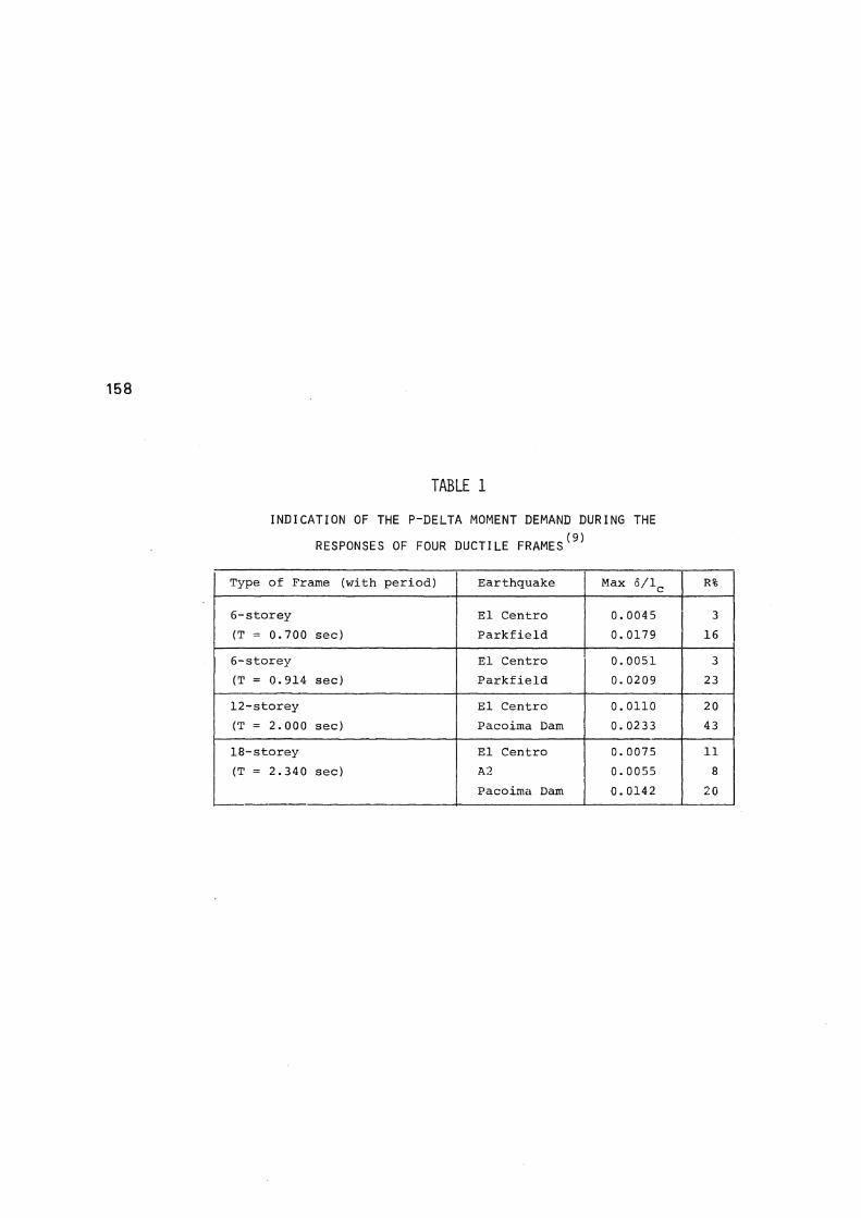
TABLE 1
INDICATION OF THE P-DELTA MOMENT DEMAND DURING THE
RESPONSES OF FOUR DUCTILE F R A M E S ( 9 )
Type of Frame (with period) Earthquake M a x 6 / l c R%
6-storey El Centre 0.0045 3 (T = 0.700 sec) Parkfield 0.0179 16
6-storey El Centro 0.0051 3 (T = 0.914 sec) Parkfield 0.0209 23
12-storey El Centro 0.0110 20 (T = 2.000 sec) Pacoima Dam 0.0233 43
18-storey El Centro 0.0075 11 (T = 2.340 sec) A2 0.0055 8
Pacoimci Dam 0.0142 20

1 5 9
FIGURE 1: TYPICAL CONFIGURATION OF A MULTISTOREY FRAME DURING SEVERE EARTHQUAKE ATTACK
(r+1)
ZZZ!* r̂TTTTTTTTTnml
(b)
L a i b & (c )
(ef)
FIGURE 2: A TYPICAL INTERMEDIATE FLOOR OF A FRAME: (a) S T O R E Y D I S P L A C E M E N T S , E A R T H Q U A K E A N D G R A V I T Y L O A D
A C T I O N S .
(b) B E A M B E N D I N G M O M E N T S R E Q U I R E D T O R E S I S T L A T E R A L S T A T I C
D E S I G N L O A D I N G .
(c) D E V E L O P M E N T O F M O M E N T S A T B E A M H I N G E S .
(d) M O M E N T P A T T E R N A T T H E D E V E L O P M E N T O F I D E A L B E A M F L E X
U R A L R E S I S T A N C E .
WITH AND WITHOUT P-DELTA EFFECT FIGURE 4 : P-DELTA MOMENTS CAUSING " C R A W L I N G "
AND LEADING TO INCREMENTAL COLLAPSE
