a contoured gap coaxial plasma gun with injected plasma ...hyperv.com/pubs/rsinak808083506_1.pdf ·...
TRANSCRIPT

A contoured gap coaxial plasma gun with injected plasma armatureF. Douglas Witherspoon,a� Andrew Case, Sarah J. Messer, Richard Bomgardner II,Michael W. Phillips,b� Samuel Brockington, and Raymond Eltonc�
HyperV Technologies Corp., Chantilly, Virginia 20151, USA
�Received 25 February 2009; accepted 17 July 2009; published online 27 August 2009�
A new coaxial plasma gun is described. The long term objective is to accelerate 100–200 �g ofplasma with density above 1017 cm−3 to greater than 200 km/s with a Mach number above 10. Suchhigh velocity dense plasma jets have a number of potential fusion applications, including plasmarefueling, magnetized target fusion, injection of angular momentum into centrifugally confinedmirrors, high energy density plasmas, and others. The approach uses symmetric injection of highdensity plasma into a coaxial electromagnetic accelerator having an annular gap geometry tailoredto prevent formation of the blow-by instability. The injected plasma is generated by numerous�currently 32� radially oriented capillary discharges arranged uniformly around the circumference ofthe angled annular injection region of the accelerator. Magnetohydrodynamic modeling identifiedelectrode profiles that can achieve the desired plasma jet parameters. The experimental hardware isdescribed along with initial experimental results in which approximately 200 �g has beenaccelerated to 100 km/s in a half-scale prototype gun. Initial observations of 64 merging injector jetsin a planar cylindrical testing array are presented. Density and velocity are presently limited byavailable peak current and injection sources. Steps to increase both the drive current and the injectedplasma mass are described for next generation experiments. © 2009 American Institute ofPhysics. �DOI: 10.1063/1.3202136�
I. INTRODUCTION
Plasma jets with high density and velocity have a num-ber of important applications in fusion energy and elsewhere,including plasma refueling, disruption mitigation in toka-maks, magnetized target fusion, injection of momentum intocentrifugally confined mirrors, plasma thrusters, and high en-ergy density plasmas.
In magnetoinertial fusion �MIF�,1–4 for example, an im-ploding material liner is used to compress a magnetizedplasma to fusion conditions and to confine the resulting burn-ing plasma inertially to obtain the necessary energy gain. Theimploding shell may be solid, liquid, gaseous, or a combina-tion of these states. The presence of the magnetic field in thetarget plasma suppresses thermal transport to the plasmashell, thus lowering the imploding power needed to compressthe target to fusion conditions. This allows the required im-ploding momentum flux to be generated electromagneticallyusing off-the-shelf pulsed power technology. Practicalschemes for standoff delivery of the imploding momentumflux are required and are open topics for research. One ap-proach for accomplishing this, called plasma jet driven MIF�PJMIF�, uses a spherical array of pulsed plasma guns tocreate a spherically imploding shell of very high velocity,high momentum flux plasma.5 This approach requires devel-opment of plasma jet accelerators capable of achieving ve-locities of 50–200 km/s with very precise timing and densityprofiles, and with high total mass and density. Low-Z plasma
jets would require the higher velocities, whereas some recentcalculations6–8 have indicated the possibility of using high-Zplasma shells at velocities of only 50–100 km/s.
Thio et al.5,9 recognized that coaxial railgun acceleratorswere potentially capable of meeting this challenge, notingthat spheromaks and field reversed configurations had al-ready achieved velocities in excess of 200 km/s, albeit withlower densities and total mass. They projected that it wouldbe possible to accelerate 200–400 �g of plasma to�200 km /s in a plasma gun with a length of no more than 1m and a muzzle diameter of less than 0.2 m, with timingprecision of better than 100 ns. Given these parameters, thedensity of the plasma jets would need to be approximately1017 cm−3.
We describe our work to develop the pulsed plasma guntechnology needed for an experimental demonstration of thePJMIF concept and also for the other applications mentionedearlier. The parameters in the previous paragraph were takenas experimental goals. Initial work used existing computa-tional and analytical tools to develop and refine a specificplasma gun concept having a novel tapered coaxial electro-magnetic �EM� accelerator profile �originally suggested byThio10� and an array of symmetric plasma injectors. The pro-file is designed to suppress the main barrier to success incoaxial guns, namely, the blow-by instability in which thearc slips past and outruns the bulk of the plasma mass.11–13
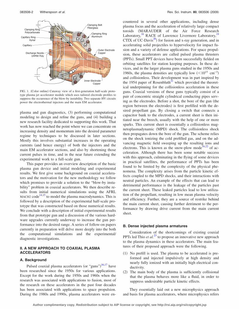
The first generation half-scale prototype gun is illustratedschematically in Fig. 1.
Our efforts to date have focused mainly on �1� develop-ing various plasma injection systems and ensuring they workreliably with the accelerator section, �2� developing a suite of
a�Electronic mail: [email protected]�Advanced Energy Systems, Inc., Princeton, NJ 08540.c�University of Maryland, College Park, MD 20742.
REVIEW OF SCIENTIFIC INSTRUMENTS 80, 083506 �2009�
0034-6748/2009/80�8�/083506/15/$25.00 © 2009 American Institute of Physics80, 083506-1
Author complimentary copy. Redistribution subject to AIP license or copyright, see http://rsi.aip.org/rsi/copyright.jsp
plasma and gun diagnostics, �3� performing computationalmodeling to design and refine the guns, and �4� building anew research facility dedicated to supporting this work. Thatwork has now reached the point where we can concentrate onincreasing density and momentum into the desired parameterregime by techniques to be discussed in later sections.Mostly this involves substantial increases in the operatingcurrents �and hence energy� of both the injectors and themain EM accelerator sections, and also by shortening thosecurrent pulses in time, and in the near future extending theexperimental work to a full-scale gun.
This paper provides an overview description of the basicplasma gun device and initial modeling and experimentalresults. We first give some background on coaxial accelera-tors and the motivation for the new methodology we followwhich promises to provide a solution to the “blow-by insta-bility” problem in coaxial accelerators. We then describe re-sults from initial numerical simulations using the AFRLMACH2 code14,15 to model the plasma macrodynamics. This isfollowed by a description of the experimental half-scale pro-totype that was constructed based on those numerical results.We conclude with a description of initial experimental resultsfrom that prototype gun and a discussion of the various hard-ware upgrades currently underway to increase the gun per-formance into the desired range. A series of follow-on paperscurrently in preparation will delve more deeply into the boththe computational simulations and the experimental/diagnostic investigations.
II. A NEW APPROACH TO COAXIAL PLASMAACCELERATORS
A. Background
Pulsed coaxial plasma accelerators �or “guns”�16,17 havebeen researched since the 1950s for various applications.Except for the work during the 1950s and 1960s when theresearch was associated with applications to fusion, most ofthe research on these accelerators in the past four decadeshas been associated with applications to space propulsion.During the 1980s and 1990s, plasma accelerators were en-
countered in several other applications, including denseplasma focus and the acceleration of relatively large compacttoroids �MARAUDER of the Air Force ResearchLaboratory,18 RACE of Lawrence Livermore Laboratory,19
CTIX of UC-Davis20� for fusion and x-ray generation, and inaccelerating solid projectiles to hypervelocity for impact fu-sion and a variety of defense applications. For space propul-sion, these accelerators are called pulsed plasma thrusters�PPTs�. Small PPT devices have been successfully fielded onorbiting satellites for station keeping purposes. In these de-vices, and in the larger plasma guns studied in the 1950s and1960s, the plasma densities are typically low ��1015 cm−3�and collisionless. Their development was in part inspired bythe 1954 paper of Rosenbluth21 which provided the theoret-ical underpinning for the collisionless acceleration in theseguns. Coaxial versions of these guns typically consist of apair of concentric straight cylindrical conducting pipes serv-ing as the electrodes. Before a shot, the bore of the gun �theregion between the electrodes� is first prefilled with the de-sired propellant gas. By closing a switch that connects acapacitor bank to the electrodes, a current sheet is then ini-tiated near the breech, usually with the help of one or moresparks. This current sheet is essentially a collisionless mag-netoplasmadynamic �MPD� shock. The collisionless shockthen propagates down the bore of the gun. The scheme relieson the shock ionizing the cold prefilled gas, and on the ad-vancing magnetic field sweeping up the resulting ions andelectrons. This is known as the snow-plow mode16,22 of ac-celeration. Although there has been some notable successwith this approach, culminating in the flying of some devicesin practical satellites, the performance of PPTs has beenfound to be limited by the complexity of the physical phe-nomena. The complexity arises from the particle kinetic ef-fects coupled to the MPD shocks, and their interactions withneutral particles. An example of the effects that can lead todetrimental performance is the leakage of the particles pastthe current sheet. These leaked particles lead to low utiliza-tion of the propellant, resulting in low mean plasma velocityand efficiency. Further, they are a source of restrike behindthe main current sheet, causing further detriment to the per-formance by drawing drive current from the main currentsheet.
B. Dense injected plasma armatures
Consideration of the shortcomings of existing coaxialPPTs led Thio et al.23 to propose an innovative new approachto the plasma dynamics in these accelerators. The main fea-tures of their proposed approach were the following.
�1� No prefill is used. The plasma to be accelerated is pre-formed and injected impulsively at high density andnearly fully ionized with an initially high electrical con-ductivity.
�2� The main body of the plasma is sufficiently collisionalthat the plasma behaves more like a fluid, in order tosuppress undesirable particle kinetic effects.
They essentially laid out a new microphysics approachand basis for plasma accelerators, where microphysics refers
Clamping RingPolycarbonate
Clamping BoltFiberglass
Clamping RingAluminum
Outer ElectrodeCopper
Inner ElectrodeCopper
Capillary RingKynar
Capillary
Discharge NozzleUHMW Poly
FIG. 1. �Color online� Cutaway view of a first-generation half-scale proto-type plasma jet accelerator module which uses tailored electrode profiles tosuppress the occurrence of the blow-by instability. Two separate HV circuitspower the electrothermal injectors and the main EM accelerator.
083506-2 Witherspoon et al. Rev. Sci. Instrum. 80, 083506 �2009�
Author complimentary copy. Redistribution subject to AIP license or copyright, see http://rsi.aip.org/rsi/copyright.jsp

here mainly to localized particle effects. The new approachtraded the microphysics problems of conventional PPTs withthe engineering challenge of creating the new pulsed plasmafeeds �injectors� that would be needed to inject the denseplasmas that meet the requirements of the new microphysicsproposed. One of the objectives of our research is to demon-strate the potential of this new microphysics approach toplasma acceleration.
However, having a plausible microphysics approach isonly half the challenge. The microphysics also needs to beimplemented in a practical macrodynamic scheme, wheremacrodynamic refers mainly to bulk magnetohydrodynamics�MHD� fluid type behavior and the associated flow geom-etries. Several challenges remain to be overcome once thishighly collisional, no prefill, microphysics approach isadopted. First, the approach requires new plasma injectors tobe developed that can deliver the dense plasma that meetsthe microphysics specifications. Second, in the main plasmaaccelerator, the notable MHD instabilities and the issues ofrestrike, skin friction, and electrode ablation and erosion willneed to be addressed and overcome.
Thio et al.9 proposed an accelerator concept as a possibleimplementation of this new approach. The accelerator con-sisted of a pair of coaxial electrodes, both electrodes havinga gradual conical taper and an EM focusing section muchlike a plasma focus device. The conical taper induces a smallcomponent of radially inward velocity at the muzzle exitwhich tends to focus the jet for a short distance before col-lisional effects cause subsequent rebound and expansion fur-ther downstream. Whether the focusing provides a net gainin the performance of the jet during its flight to the targetremains to be determined, since the induced compressionalheating may take back whatever gains were made byfocusing.
The acceleration chamber would be thoroughly flushedwith helium and evacuated �i.e., no gas prefill�. The twoelectrodes are electrically connected to the two terminals of acapacitor bank or pulse forming network �PFN�. Before ashot, the capacitor bank �or PFN� is charged to the desiredvoltage, which appears simultaneously on the electrodes. Therequired plasma mass is introduced into the accelerationchamber by a set of extremely low-jitter ��10 ns� pulsedplasma injector feeds arranged annularly near the breech.The plasma is then launched in the form of a plasma “fan”�or “plume”� radially inwards toward the axis of the innerelectrode. The plasma fans join to form a dense plasma sheetthat closes the external circuit and initiates the main currentpulse to accelerate the plasma sheet down the accelerator. Asomewhat similar technique was used by Kohno et al.24 in aplasma opening switch experiment.
The requisite amount of plasma is injected into the ac-celerator using pulsed electrothermal capillary dischargeswith ablative polyethylene walls. Ablative capillaries havebeen used successfully for large electrothermal guns,25 injec-tors to high energy railguns,26 plasma thrusters,27 and in ex-periments involving laser propagation through long plasmachannels,28–31 to name just a few applications. Ultimately theablative walls will be replaced with nonablative refractoryceramics, as has been accomplished for pulsed soft x-ray
sources32–35 and for high energy pulsed thermal spraydevices.36 This will allow clean and repetitive operation. TheH2 or D2 �or other, higher-Z gases� in this case are intro-duced by other means, which are currently under develop-ment at HyperV and will be addressed in future papers.
C. The blow-by instability
Plasma acceleration techniques which depend on Lor-entz j��B� forces are generally susceptible to MHD instabili-ties that can deteriorate the plasma jet acceleration processsignificantly, induce restriking and secondary arcs, and eventerminate plasma jets. Therefore, it is crucial to understandthe MHD instabilities and optimize the design of the accel-erator to avoid them in order to achieve the desired plasmajet acceleration. The major instabilities include the blow-byand Rayleigh–Taylor instabilities. The Rayleigh–Taylor in-stability encompasses filamentation and interchange insta-bilities.
The main macrodynamic problem in coaxial plasma jetacceleration is the blow-by instability that develops duringthe acceleration phase. The blow-by instability has its originin the r−2 radial dependence of the magnetic pressure. If theplasma has an initially uniform density and thickness �uni-form mass distribution�, its acceleration will be higher alongthe inner electrode than along the outer one. The fastermovement along the inner electrode produces a “backwardcanting” of the current-carrying plasma. The canting currentsheet then develops a large axial component which producesa Lorentz force with a radial outward component. This radialacceleration causes a runaway effect in which increasinglymore plasma mass is removed from the high velocity region,making the imbalance of the magnetic field pressure againstthe adverse density profile more severe. As can be seen inFig. 2, the blow-by instability accelerates a small piece ofplasma to a disproportionately high velocity, while leaningmost of the plasma mass against the outer electrode where iteventually exits at much lower velocity.
Blow-by was previously investigated by Baker et al.11,12
More recently, Cassibry et al.13 performed a detailed compu-tational study of the blow-by instability in straight coax ac-celerators and found that for straight coax guns, the principalacceleration phase must be limited to no more than about1 �s and the electrode radius ratio should be no more thanabout 2:1. These constraints are too severe to achieve the
Outer Electrode
Inner Electrode
Outer Electrode
CL
�
�
Hot, Low Density
Plasma Races AheadAlong Inner Electrode
Cool, High DensityPlasma Lags
Behind
Lorentz ForceStrongest Near Axis,⊥ to Current
FIG. 2. �Color online� Illustration of blow-by in a straight coax acceleratordriven by a HV capacitor. The larger magnetic field and higher currentdensity at smaller radii causes an imbalance in the nominally axially di-rected Lorentz force, resulting in a faster acceleration of plasma near theinner electrode, which runs away from the bulk of the plasma.
083506-3 Witherspoon et al. Rev. Sci. Instrum. 80, 083506 �2009�
Author complimentary copy. Redistribution subject to AIP license or copyright, see http://rsi.aip.org/rsi/copyright.jsp

goals of this project, but Thio10 and Cassibry37 also beganinvestigating the possibility of combining pulsed injectionalong with shaping of the electrode profiles as a means tosuppress the blow-by instability and thus achieve higherperformance.
D. Coaxial accelerators with tailored electrodegeometries
Cassibry37 and Thio10 had looked at a curved profile co-axial configuration, which showed some promise but was notinvestigated experimentally. Our approach to addressing theblow-by problem uses a novel shaping of the electrodesoriginally suggested by Thio.10 This is basically a furtherevolution of his straight conical tapered gun mentioned in thelast section and the curved profile investigated by Cassibry.37
Our initial modeling effort, described in Sec. IV, focused onanalyzing this approach and identifying geometries and pa-rameters which would avoid the blow-by. Although someminor modifications to Thio’s10 original suggestion werefound to be necessary, the simulations supported the basicconcept.
We thus adopt Thio’s10 microphysics approach that useshighly collisional plasma in a shaped coaxial plasma gun,along with plasma sources that impulsively inject a densefast-moving preformed plasma armature into a coaxial gunhaving no initial prefill. Ideally, no external switch would berequired, letting the injected plasma itself act as a closingswitch, but in practice one may be required.
Assuming an impulsively injected plasma armature, wenow consider the physics issues and challenges of control-ling the macrodynamics of the plasma slab so that the globalcharacteristics of the plasma acceleration can be achieved.
III. CONTROL OF PLASMA MACRODYNAMICS
A. The injection and transition regions
Figure 3 shows the baseline geometry for the acceleratorbased on Thio’s10 earlier suggestion. This electrode geometryprovides for a breech section �between A and B� that is or-thogonal to the gun axis. It was later found to be necessary tochange this to an oblique angle, but the following discussionremains essentially unchanged. In this section of the gun, theinjected plasma initially flows radially inward toward thegun axis. The initial discharge, initiated by the injectedplasma, is axial between the electrodes �and mostly so for theangled injector case�, thus forming a fat z-pinch that rapidlyaccelerates the plasma radially inwards in the region betweenA and B to supersonic speeds. As the plasma enters the tran-sitional region between B and C, its leading edge is at theouter electrode. Having the leading edge of the plasma at theouter electrode is the preferred inclination for the plasma tocounter the blow-by instability. Thio10 and Cassibry37 callthis the “forward canting” of the plasma sheet. Furthermore,the plasma sees a convex curvature at the outer electrode,versus a concave curvature at the inner electrode. The con-vex curvature produces an expanding fan of the Mach lines�characteristics� for the flow at the outer electrode, givingrise to an expansion of the flow at the outer electrode.
The flow expansion helps accelerate the plasma alongthe outer electrode, reducing the density of the plasma nearthe outer electrode. On the other hand, the concave curvaturerelative to the flow at the inner electrode produces conver-gence of the Mach lines for the flow at the inner electrodebetween B and C, making the flow bend into itself, givingrise to compression of the flow at the inner electrode. Theincreased plasma density near the inner electrode tends toreduce the acceleration produced by the greater Lorentz forcethere. A favorable density profile, monotonic with respect tothe magnetic pressure, is thus created by the way the plasmais injected and by the chosen curvatures of the entry andtransition regions. These features help to suppress �or at leastdelay� the occurrence of the blow-by. The electrode profilesare chosen so that the bends produce smooth transitions inthe flow, making the compression or expansion as isentropic�shockless� as possible. Our studies showed that the rightangle turn is too sharp, while 45° is about right, as discussedlater in Sec. IV B.
In the above discussion, we have borrowed fluid dynam-ics concepts established for steady-flow, even though theflow in our accelerator is unsteady. However, just as is com-mon experience in similar cases, the qualitative descriptionsremain essentially correct, while the deviations from the
FIG. 3. Baseline plasma jet accelerator geometry for simulations. The rightangle turn in this drawing turns out to be too large, and an angle closer to45° is much better. See Figs. 4 and 5 for examples of simulated plasma flowin this geometry.
083506-4 Witherspoon et al. Rev. Sci. Instrum. 80, 083506 �2009�
Author complimentary copy. Redistribution subject to AIP license or copyright, see http://rsi.aip.org/rsi/copyright.jsp

steady-flow results lie in the quantitative details. The two-dimensional �2D� MHD modeling validated this expectationand the qualitative behavior of the flow as described above isobserved in the simulations.
B. The intermediate acceleration stage
The section of the accelerator between C and D is calledthe intermediate acceleration stage. As the plasma enters thisstage, the driving current reaches its peak, and the full Lor-entz force is brought to bear on the plasma.
A taper is maintained in the outer electrode to mechani-cally induce a focusing of the flow toward the axis, the ideabeing that after the flow exits from the accelerator, the radi-ally inward velocity component of the flow could helpcounter the thermal expansion of the jet radially, to producea focusing flow or at least a collimated flow over the requireddistance.
A gradually decreasing concave curvature is maintainedalong the inner electrode to continue to reduce the risk of anyblow-by instability, seeking to maintain an organized andcompact acceleration of the plasma. This is done at the ex-pense of some constriction of the flow and thus some reduc-tion in the acceleration of the plasma through the constric-tion. This is compensated, however, by the final accelerationstage, in which the concavity in the curvature becomes con-vex at point D, beyond which the supersonic flow expandsalong the inner electrode.
C. The final accelerating and focusing stage
The region indicated by points D, E, F, and G representsthe final accelerating and focusing stage. The driving currentis maintained as close as possible to a flat top equaling itspeak value at the point C until the plasma first reaches nearthe top of the inner electrode �point F�. The driving current isultimately allowed to fall to zero after that as the plasmareaches the point G close to the muzzle.
In addition to the Lorentz acceleration, the supersonicexpansion around the inner electrode beyond the point Dcontributes to the total acceleration of the flow. The convexcurvature of the inner electrode also bends the flow towardthe axis. Because of the cylindrical geometry, the flow ex-pansion soon ceases and gives in to compression due to con-vergence of the flow toward the axis. Nevertheless, furtheracceleration of the flow occurs due to the increasing Lorentzforce.
Beyond point D, the plasma at the outer electrode makesgains in the axial position of the plasma at the inner elec-trode, producing a forward tilting of the current flow. Theforward tilting of the current produces a force that acceler-ates the plasma toward the axis, as well as axially, thus fo-cusing the flow electromagnetically, similar to a denseplasma focus device. The forward tilting of the current in-creases as the plasma moves toward the point G, producing aconical z-pinch with the tip of the inner electrode as thevertex. The radial pinching of the flow intensifies as the ver-tex angle of the conical z-pinch decreases, and leads to for-ward electrothermal acceleration of the plasma axially sup-ported by the intense magnetic pressure due to the z-pinch at
the top of the inner electrode. To further enhance the nearlyisentropic compression of the flow, a small concave curva-ture is provided on the outer electrode in this region. Thecombination of the EM and electrothermal acceleration pro-pels the plasma forward as a relatively focused jet. The outerelectrode has an extended section at the muzzle to provide aguided drift of the accelerated plasma jet to allow it to coolradiatively and convectively in contact with the wall. Thislowers the sound speed of the jet and increases its Machnumber rapidly as it exits from the muzzle of the accelerator.The high Mach number then maintains the collimation of thefocused jet.
IV. ACCELERATOR DESIGN
A series of simulations were performed to find a suitablegeometrical configuration and set of parameters that sup-presses plasma blow-by and allows at least 100 �g ofplasma to be accelerated to 200 km/s. We will briefly sum-marize the initial modeling results in this section, while de-ferring to future papers for more detailed analysis. The simu-lations validated the basic conceptual approach with therestriction that the right angle injection needed to be reduced.
A. The MHD code
To understand the dynamics of contoured coaxial plasmaguns and the effect electrode shape has on performance, pre-liminary design simulations were carried out using theMACH2 code.14,15
MACH2 is a 2.5-dimensional single-fluidMHD simulation code. The code follows the nonlinear evo-lution of density, velocity, and magnetic field, as well as theelectron and ion specific internal energies. The code solvesequations for mass continuity, fluid momentum, electron, andion specific internal energies, radiation energy density, andmagnetic induction. Quantities are solved on a 2D Cartesianor cylindrical mesh; for the coaxial geometries studied here,a cylindrical mesh was used. The equations are coupledthrough equation of state �EOS� and transport coefficients.MACH2 features a range of EOS and transport models includ-ing table look-up that can utilize the Los Alamos NationalLaboratory SESAME EOS database.38 Our calculations usedthe ideal gas EOS, Spitzer resistivity, and Braginskii trans-port coefficients. The magnetic induction equation can op-tionally include a Hall effect term in certain geometries,which unfortunately did not include the geometry of interesthere. The Hall effect is thought to have an influence on theparticle dynamics on the trailing edge of the plasma blob,which may lead, in certain circumstances, to detachment ofthe current armature. Other than the possibility of detach-ment, it is not expected to appreciably change the accelera-tion of the plasma blob. The Hall effect will be left for futurestudy.
A multiblock grid with arbitrary quadrilateral cells andboundary-fitted coordinates is used, which makes possiblethe simulation of a large variety of complex geometries andboundary conditions. Perfectly conducting walls are assumedon the electrode surfaces. Blocks are connected by overlap-ping ghost cells. An insulating boundary is assumed at thebreech of the gun. For cylindrical geometry, the quantity rB�
083506-5 Witherspoon et al. Rev. Sci. Instrum. 80, 083506 �2009�
Author complimentary copy. Redistribution subject to AIP license or copyright, see http://rsi.aip.org/rsi/copyright.jsp

is computed on the insulating surface using Ampere’s law.These computations used both an LRC circuit model and aprescribed current profile of a shape that can be generated bya PFN. At the beginning of the computation, initial plasmaconditions are prescribed on the blocks. For these simula-tions, an initial annular slug of constant density with an ini-tial velocity directed down the bore of the gun is assumed.This mimics the initial plasma produced by capillary injec-tion. Though these initial conditions may seem highly sim-plified, the initial density profile was not found to have anappreciable effect on the outcome: during the first microsec-ond or two, the plasma tends to thermally expand to fill thebreech before acceleration gets underway.
B. The wasp profile
Initial simulations used a “Wasp” profile for the centerelectrode �so-called because of its similarity to a wasp’sbody� with 90° injection of the plasma, as illustrated earlierin Fig. 3. After running a number of test cases with thisconfiguration, it was observed that this design overcorrectsfor blow-by. The problem lies with the sharp right angle turnthe plasma must make going around the initial corner, whereit transitions from the z-pinch into the main accelerator sec-tion. This is illustrated in Fig. 4. The momentum of theplasma causes formation of a pocket of very low densityplasma just around the corner which rapidly accelerates un-der both electrothermal and EM forces up along the outerelectrode. Meanwhile the main bulk of the plasma continuesforward curving around along the inner electrode, generatingthe very steep density gradient seen in the figure.
The current density peaks in the regions of high conduc-tivity, i.e., where the temperature and charge carrier densityare high, as seen in the joule heating contours in Fig. 4. Asthe plasma accelerates around the curve, it necessarily takes
the current attachment point on the outer electrode with it.This stretches out the current channel very rapidly. The re-sulting j��B� forces then act to further compress the plasmaradially inwards against the inner wall. The result is a “blow-by” that occurs on the outside rather than on the inside as ina straight coax.
A set of initial conditions could not be found that cir-cumvents this problem for this specific injection geometry. Inthis particular configuration, the curvature is excessive andovercorrects, causing the blow-by to occur on the outside.This suggests that the convexity of the outer electrode andthe concavity of the inner electrode in the transition from thez-pinch to the main acceleration section needs to be reduced.
C. Systematic tuning of profile curvature
Based on the simulations described above, a new seriesof simulations were performed to test the original wasp elec-trode profile, but with an angled injector to provide the cor-rect curvature. The best angle seemed to be around 45°, aswas also indicated by another series of simulations usingsimple circular arc profiles to study armature dynamics. Thedetailed behavior of the flow from a well performing simu-lation of the wasp electrode profile is shown in Fig. 5, whichshows contours of the kinetic energy density 1 /2�v2. As canbe seen from these figures, a compact, well-organized plasmaslug is formed early in time. The curvature of the electrodeprofile continues to maintain a compact plasma as it acceler-ates up the annular channel, very much as expected theoreti-cally and described in Sec. III above. A number of runs weremade with a range of parameters for the initial conditions�injection velocity, density, temperature, and plasma mass�.The current density is confined primarily to the compactplasma armature for these best runs. This successful profile,and the range of parameters determining the initial condi-tions, were later used as the baseline for the design and de-velopment of the prototype plasma accelerator.
The plasma is injected at the correct angle to allow thearmature to hold together as it accelerates down bore. Thej��B� forces on each end of the armature are balanced so thatthe extra distance the inner attach point has to travel aroundthe convex curve of the inner electrode �region C in Fig. 3�just allows it to maintain pace with the attach point on theouter electrode. As the armature starts to compress near thethroat �region D in Fig. 3�, the plasma compresses and a hintof blow-by can be seen near the outer wall, but the compress-
-
+
Density at 11.5 µs-
+
Density at 13 µs
-
+
Joule heating at 11.5 µs-
+
Joule heating at 13 µs
FIG. 4. �Color online� MACH2 density and joule heating contours at 11.5 and13 �s for baseline Wasp profile run hyperv37. Highest density is the innerred contour, lowest the outer dark blue contour. Velocity plots �not shown�indicate the plasma rapidly accelerating around the corner, leaving a lowdensity pocket there which prevents significant current flow.
CL
-
+
4 µs
CL
-
+
5 µs
CL
-
+
6 µs
CL
-
+
6.6 µs
CL
-
+
7.4 µs
FIG. 5. �Color online� MACH2 kinetic energy density contours for a 200 �g,200 km/s case for a full-scale “wasp” profile. The total gun length is 75 cm,muzzle diameter is 15 cm, and the diameter at the angled injection point is�33 cm.
083506-6 Witherspoon et al. Rev. Sci. Instrum. 80, 083506 �2009�
Author complimentary copy. Redistribution subject to AIP license or copyright, see http://rsi.aip.org/rsi/copyright.jsp

ing plasma prevents it from growing. As the plasmatravels through the throat and emerges on the other side itrapidly accelerates toward the axis where it compresses tovery high density and then rapidly exits through the muzzle.The bulk flow velocity in the muzzle region of these simu-lations was about 200 km/s with densities in the range of1016–1017 cm−3 with total mass on the order of200–400 �g. The bulk flow velocity is defined as Vbulk
= �2Ekinetic /Mtotal�1/2. The plasma jet takes on a “smoke-ringlike” structure in most of these simulations with a lowdensity core near the axis, as seen in Fig. 5.
Of particular interest is the potential efficiency of theseguns. An estimate is provided by the simulation, which out-puts total plasma kinetic energy Ekinetic=�1 /2�v2d3x, energystored in the magnetic field Emagnetic=� B2
2�0d3x, and the en-
ergy dissipated as joule heating Ejoule=�I2Rdt. We define theoverall gun efficiency as
� =Ekinetic
1
2CVi
2 −1
2CVf
2
, �1�
where the final capacitor voltage is taken as the peak nega-tive voltage on the capacitor bank at the time of current zeroas it rings down. This is essentially equivalent to assumingthat all stored magnetic field energy can be recovered in theexternal circuit. If we further assume an external resistanceof 1 m�, then the gun efficiency is roughly 59% for the casein Fig. 6�a� and 75% for the case in Fig. 6�b�. In all cases welooked at, the total joule heating in the plasma was smallcompared to the kinetic energy or the magnetic field energy,being typically only 10%–15% of the former, and the simu-lation gun efficiencies ranged between 35% and 75%. Higherefficiencies are seen for the more massive armatures at lowervelocity �such as 50 km/s�, as would be expected. This isgood news since just these types of plasma jets appear tohave promise for PJMIF. These simulations have not in-cluded various other effects �such as skin friction drag�which will tend to depress the overall efficiency, and higherexternal circuit resistance which will need to be kept to 1 or2 m� �skin effect in the rails themselves however is negli-gible�. In any case, efficiencies in the range of 40%–60%appear to be possible and are consistent with reported railgunefficiencies using inductive recapture39 and in pulsed induc-tive thrusters.40 This will require additional work to clarify.
V. PROTOTYPE ACCELERATOR
A cutaway view of the first-generation half-scale proto-type plasma accelerator was shown earlier in Fig. 1. Thedesign is based on the wasp profile and MACH2 simulationsdescribed earlier, but the half-scale conforms to the physicalconstraints of installation onto the Maryland CentrifugaleXperiment �MCX� vacuum chamber at the University ofMaryland, where it was intended as a driver of rotations in acentrifugally confined mirror plasma.41 Modeling similar tothat of the last section predicted the half-scale gun couldaccelerate 80–100 �g of polyethylene plasma to �90 km /swith a 9 �s current pulse of �190 kA. The experimental
results described below confirm these performance predic-tions.
The accelerator consists of two main copper alloy elec-trodes with a ring of 32 equally spaced capillary dischargeinjector units. The capillaries are mounted in an insulatingblock of Kynar so that they float electrically with respect tothe two main electrodes. The tungsten exit nozzle of eachcapillary is recessed behind a polyethylene nozzle, whichprovides a tapered transition to the breech of the main co-axial accelerator. The two main electrodes are held togetherby two stiff ring structures using 32 insulating fiberglassstuds. The Kynar ring also provides high-voltage �HV� insu-lator standoff between the inner and outer electrodes. At-tempts to operate without an external switch have been gen-erally unsuccessful to date. Even at an ambient pressure of10−5 Torr, the structure does not hold off more than about6 kV after the first shot. It is currently unknown whether thisis a fundamental limitation, or whether it could be avoidedwith a modified design, perhaps using a ceramic insulatorinstead of plastic. This will be readdressed in the future.
The main electrodes were machined from solid cylindri-cal ”logs” of copper alloy. The inner wall profiles were ma-chined with numerically controlled lathes using profile datafrom the MHD simulations.
A. Experimental facility
The experimental facility is shown in Fig. 7. The gun ismounted on a support stand and connected to an octagonally
0
2
4
6
8
10
12
14
0 1 2 3 4 5 6 7 8 9 10 11 12 13 14 150
50
100
150
200
250
Ene
rgy
(kJ)
,C
urre
nt(1
05A
mps
)
Vel
ocity,
km/s
Time, microsec
VbulkEkinetic
EmagneticEjoule
Current
(a)
0
2
4
6
8
10
12
14
0 1 2 3 4 5 6 7 8 9 10 11 12 13 14 150
50
100
150
200
250
Ene
rgy
(kJ)
,C
urre
nt(1
05A
mps
)
Vel
ocity,
km/s
Time, microsec
VbulkEkinetic
EmagneticEjoule
Current
(b)
FIG. 6. MACH2 simulations show performance capability of coax gun for �a�low mass �400 �g� and �b� high mass ��8000 �g� armatures. Curves peakand then drop off in �a� as plasma leaves computational zone at muzzle exit.
083506-7 Witherspoon et al. Rev. Sci. Instrum. 80, 083506 �2009�
Author complimentary copy. Redistribution subject to AIP license or copyright, see http://rsi.aip.org/rsi/copyright.jsp
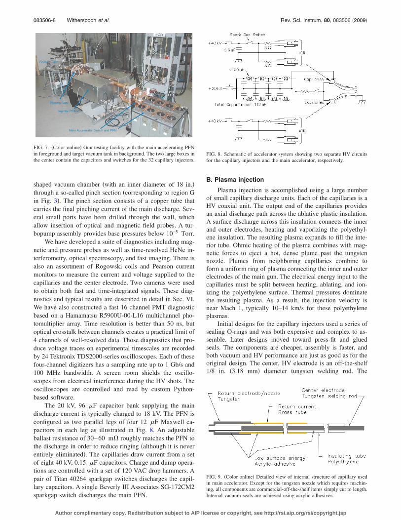
shaped vacuum chamber �with an inner diameter of 18 in.�through a so-called pinch section �corresponding to region Gin Fig. 3�. The pinch section consists of a copper tube thatcarries the final pinching current of the main discharge. Sev-eral small ports have been drilled through the wall, whichallow insertion of optical and magnetic field probes. A tur-bopump assembly provides base pressures below 10−5 Torr.
We have developed a suite of diagnostics including mag-netic and pressure probes as well as time-resolved HeNe in-terferometry, optical spectroscopy, and fast imaging. There isalso an assortment of Rogowski coils and Pearson currentmonitors to measure the current and voltage supplied to thecapillaries and the center electrode. Two cameras were usedto obtain both fast and time-integrated signals. These diag-nostics and typical results are described in detail in Sec. VI.We have also constructed a fast 16 channel PMT diagnosticbased on a Hamamatsu R5900U-00-L16 multichannel pho-tomultiplier array. Time resolution is better than 50 ns, butoptical crosstalk between channels creates a practical limit of4 channels of well-resolved data. Those diagnostics that pro-duce voltage traces on experimental timescales are recordedby 24 Tektronix TDS2000-series oscilloscopes. Each of thesefour-channel digitizers has a sampling rate up to 1 Gb/s and100 MHz bandwidth. A screen room shields the oscillo-scopes from electrical interference during the HV shots. Theoscilloscopes are controlled and read by custom Python-based software.
The 20 kV, 96 �F capacitor bank supplying the maindischarge current is typically charged to 18 kV. The PFN isconfigured as two parallel legs of four 12 �F Maxwell ca-pacitors in each leg as illustrated in Fig. 8. An adjustableballast resistance of 30–60 m� roughly matches the PFN tothe discharge in order to reduce ringing �although it is neverentirely eliminated�. The capillaries draw current from a setof eight 40 kV, 0.15 �F capacitors. Charge and dump opera-tions are controlled with a set of 120 VAC drop hammers. Apair of Titan 40264 sparkgap switches discharges the capil-lary capacitors. A single Beverly III Associates SG-172CM2sparkgap switch discharges the main PFN.
B. Plasma injection
Plasma injection is accomplished using a large numberof small capillary discharge units. Each of the capillaries is aHV coaxial unit. The output end of the capillaries providesan axial discharge path across the ablative plastic insulation.A surface discharge across this insulation connects the innerand outer electrodes, heating and vaporizing the polyethyl-ene insulation. The resulting plasma expands to fill the inte-rior tube. Ohmic heating of the plasma combines with mag-netic forces to eject a hot, dense plume past the tungstennozzle. Plumes from neighboring capillaries combine toform a uniform ring of plasma connecting the inner and outerelectrodes of the main gun. The electrical energy input to thecapillaries must be split between heating, ablating, and ion-izing the polyethylene surface. Thermal pressures dominatethe resulting plasma. As a result, the injection velocity isnear Mach 1, typically 10–14 km/s for these polyethyleneplasmas.
Initial designs for the capillary injectors used a series ofsealing O-rings and was both expensive and complex to as-semble. Later designs moved toward press-fit and gluedseals. The components are cheaper, assembly is faster, andboth vacuum and HV performance are just as good as for theoriginal design. The center, HV electrode is an off-the-shelf1/8 in. �3.18 mm� diameter tungsten welding rod. The
���� �������� � ��� ��� ���
������ ���
������ �����
������ ����
FIG. 7. �Color online� Gun testing facility with the main accelerating PFNin foreground and target vacuum tank in background. The two large boxes inthe center contain the capacitors and switches for the 32 capillary injectors.
FIG. 8. Schematic of accelerator system showing two separate HV circuitsfor the capillary injectors and the main accelerator, respectively.
FIG. 9. �Color online� Detailed view of internal structure of capillary usedin main accelerator. Except for the tungsten nozzle which requires machin-ing, all components are commercial-off-the-shelf items simply cut to length.Internal vacuum seals are achieved using acrylic adhesives.
083506-8 Witherspoon et al. Rev. Sci. Instrum. 80, 083506 �2009�
Author complimentary copy. Redistribution subject to AIP license or copyright, see http://rsi.aip.org/rsi/copyright.jsp
grounded outer conductor is a brass cylinder. The nozzleelectrode is tungsten. A high density polyethylene tube pro-vides the HV insulation and ablative mass. An assemblydrawing of the final design is shown in Fig. 9. The capillariescan be seen protruding from the rear of the accelerator in Fig.10, with the internal mounting details in the annular breechof the accelerator illustrated in Fig. 11.
Once a capillary establishes a surface discharge, its re-sistance drops as the increasing capillary current heats theplasma. Initially, this led to the concern that the capillaryarray would operate unevenly, i.e., the voltage would droptoo low to complete the discharge initiation of the remainingcapillaries once the first one went. This would result in ahighly asymmetric injection into the main gun. Such highasymmetry would accelerate the development of theRayleigh–Taylor instability and sharply limit gun perfor-mance. To avoid this situation, early designs placed a ballastresistor in series with each capillary, but the explicit ballastresistors ultimately turned out to be unnecessary, since thestray �inductive� impedances in the circuit were found to besufficient to maintain balance.
We have established reliable symmetric operation of 32capillaries �and 64 in the TwoPi device discussed later� byconnecting each capillary to the switch through a single
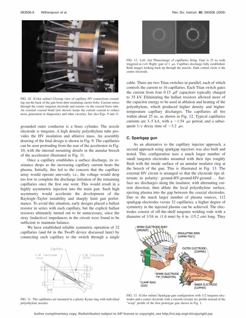
cable. There are two Titan switches in parallel, each of whichcontrols the current to 16 capillaries. Each Titan switch gatesthe current from four 0.15 �F capacitors typically chargedto 35 kV. Eliminating the ballast resistors allowed more ofthe capacitor energy to be used in ablation and heating of thepolyethylene, which produced higher density and higher-temperature capillary discharges. The capillaries all firewithin about 25 ns, as shown in Fig. 12. Typical capillariescurrents are 3–5 kA, with a �1.54 �s period, and a subse-quent 1 /e decay time of �3.2 �s.
C. Sparkgap gun
As an alternative to the capillary injector approach, asecond approach using sparkgap injectors was also built andtested. This configuration uses a much larger number ofsmall tungsten electrodes mounted with their tips roughlyflush with the inside surface of an annular insulator ring atthe breech of the gun. This is illustrated in Fig. 13. Theexternal HV circuit is arranged so that the electrode tips al-ternate in polarity: ground-HV-ground-HV-ground…. Sur-face arc discharges along the insulator, with alternating cur-rent direction, then ablate the local polyethylene surface,ejecting plasma into the gap between the coaxial electrodes.Due to the much larger number of plasma sources, 112sparkgap electrodes versus 32 capillaries, a higher degree ofsymmetry in the injected plasma can be achieved. The elec-trodes consist of off-the-shelf tungsten welding rods with adiameter of 1/16 in. �1.6 mm� by 6 in. �15.2 cm� long. They
FIG. 10. �Color online� Closeup view of capillary HV connections extend-ing out the back of the gun from their insulating carrier bolts. Current entersthrough the center tungsten electrode and returns via the coaxial brass tube.An external coaxial braid �not shown� keeps the current coaxial to reducenoise generation in diagnostics and other circuitry. See also Figs. 9 and 11.
FIG. 11. The capillaries are mounted in a plastic Kynar ring with individualpolyethylene nozzles.
FIG. 12. Left: fast PImaximage of capillaries firing. Gate is 25 ns widetriggered at t=0. Right: gate of 1 �s. Capillary discharge fully established.Both images looking back up through the muzzle. Dark central circle is thecenter electrode.
FIG. 13. �Color online� Sparkgap gun configuration with 112 tungsten elec-trodes and a center electrode with a smooth circular arc profile instead of the“wasp” profile of the first prototype gun shown in Fig. 1.
083506-9 Witherspoon et al. Rev. Sci. Instrum. 80, 083506 �2009�
Author complimentary copy. Redistribution subject to AIP license or copyright, see http://rsi.aip.org/rsi/copyright.jsp

are carefully press-fit into a slightly undersize hole in thepolyethylene, forming a tight vacuum seal that allows basepressures into the 10−6 Torr range. Figure 14 shows the HVconnections surrounding the gun. There are seven switches,each of which connects two 0.15 �F capacitors to 16 elec-trodes. A combined total of almost 0.7 MA is driven throughthe 112 sparkgaps generating the injected plasma.
D. TwoPi test fixture
The “TwoPi” test fixture was built to allow developmenttesting of large capillary arrays and their associated HV cir-cuitry. The initial version used a disk-shaped vacuum cham-ber with an inner diameter of 19.5 in. �49.5 cm� and innerheight of 2 in. �5.1 cm�. 64 radially inward pointing capillar-ies �essentially identical to those used on the gun� are ar-ranged uniformly around the periphery, as seen in Fig. 15.Large top and bottom acrylic viewing flanges allow opticalprobing and imaging of the plasma as it emerges from thecapillaries and propagates toward the center. Test resultsfrom a slightly smaller diameter TwoPi with an upgradedpower supply are described later in Sec. VI H.
VI. EXPERIMENTAL RESULTS
We discuss below typical characteristics for the half-scale prototype gun used on MCX. Variations in the ballastresistances, fill pressure, and other machine parameterswere observed to shift these numbers. For example, theelectron density was found to increase from 4�1014 to
6�1014 cm−3 when the ballast resistor was decreased from8 to 0 �. For purposes of definiteness and direct compari-sons, all measurements quoted below are made with 0 �ballast resistance on the capillary plasma injectors and a1 �s delay between firing the capillaries and the main PFN.The background pressure is less than 10−5 Torr of air �i.e.,no separate gas filling�.
A. Gun electrical
The main gun’s current and voltage waveforms are rou-tinely measured. A Rogowski coil records peak currents ofabout 174 kA on each shot. The first half-cycle of the currentring lasts 22.8 �s, and the reverse current is 44% of the peakcurrent �see Fig. 16�. Voltage is obtained by a Pearson moni-tor measuring current through a 1 k� resistor across thegun’s breech. The current waveform varies smoothly overthe course of the shot, suggesting that any restrikes or fila-mentation provide only gradual changes to the gun imped-ance. Additional Rogowski coils measure the current to indi-vidual capillaries. These Rogowski coils show 5 kA percapillary.
B. Visible light imaging
A Nikon D70s digital camera routinely gives time-integrated color pictures of the plasma discharge from vari-ous angles. These typically show a bright blue-white plasmaflowing from the gun muzzle and gradually expanding down-stream, as seen in Fig. 17. A pink plasma fills the targetchamber, and a dimmer blue plasma rebounds off the backwall of the chamber. The interior of the gun is filled with abright blue plasma, and there is often evidence for distinctbright-white filaments between the inner and outer electrodes�future work will attempt to determine when and where theseoccur within the gun�. Photographs of the capillary plasmaplumes taken without firing the main PFN confirm that allcapillaries fire on virtually every shot �Fig. 12�.
A fast PImax camera �model 7489-0004� is used to im-age the gun plasma on submicrosecond time scales. It con-firms that the capillaries fire simultaneously within 25 ns.The PImax shows the gun produces a dense bright stream of
FIG. 14. �Color online� Rear view of sparkgap gun with main bank discon-nected to show only the 112 sparkgap injectors firing.
FIG. 15. �Color online� Left: arrangement of the original TwoPi test fixtureshowing copper bus plates, ballast resistors, capacitors, switches, andvacuum vessel. Right: Nikon open shutter photograph of a test shot in origi-nal TwoPi test fixture.
-100
-50
0
50
100
150
0 10 20 30 40
Cur
rent
(kilo
ampe
res)
Time (microseconds)
FIG. 16. �Color online� Main accelerating current rings due to impedancemismatch.
083506-10 Witherspoon et al. Rev. Sci. Instrum. 80, 083506 �2009�
Author complimentary copy. Redistribution subject to AIP license or copyright, see http://rsi.aip.org/rsi/copyright.jsp

plasma �Fig. 18�. If the background pressure is raised to thevicinity of 1 mTorr, the stream of plasma condenses into adiscrete blob.
Photodiodes have been positioned to look across theplasma flow. These measure speeds of the luminous frontranging up to �143 km /s for some gun configurations.
C. Spectrometry
We used a compact Ocean Optics, Inc. survey spec-trograph to identify interesting regions in the plasma spec-trum, time-integrated over the event. It showed spectra con-sistent with a 2:1 hydrogen-to-carbon ratio, as expected forthe ablative polyethylene capillaries used for plasma injec-tion. Interesting regions identified by the spectrograph werefurther examined using a 1 m stigmatic Czerny/Turner spec-trometer �Acton Model 410� with the PImax camera previ-ously mentioned used for capturing the spectra. It was
coupled to the experiment by two 100 �m diameter fiber-optic cables aligned along the entrance slit, thus permittingtwo simultaneous views of the plasma, e.g., axial and radial.The monochromator was equipped with an 1800grooves/mm grating for a nominal reciprocal linear disper-sion at the exit of 0.5 nm/mm. With a pixel size of 0.011 mmat the charge coupled device �CCD�, this dispersion trans-lates to nominally 0.006 nm/pixel at the detector output.Hence, a detector coverage of 1024 pixels yields a wave-length span of nominally 6.1 nm at any one wavelength set-ting. A spectral resolution of 6 pixels �as determined fromspectral lamps� results both from the selection of a 50 �mwide entrance slit and from a somewhat larger pixel size�16 �m� for the image intensifier in front of the CCD.
Spectral lines from neutral hydrogen �Balmer series�, aswell as carbon atoms up to 3 times ionized �C IV spectra� arerecorded and analyzed. The intensity ratio of carbon-ionlines yields an electron temperature in the slug as high as4–5 eV, and 5–6 eV in the gun itself when viewed axially.These are based on calculations42 of ionization balance �seeFig. 19�. Interestingly, neutral C I emission is not observed,implying an electron temperature greater than �2 eV.
Doppler shift measurements along the axis of the gunindicate a mean C+ velocity of 80–90 km/s, with a lessercomponent exceeding 100 km/s �see Fig. 20�. There is also asomewhat stationary component �arising either at the gun orat the output window� that at times distinctly shows a portion
FIG. 17. �Color online� Nikon open shutter photograph of bright jet plumein vacuum tank. One arm of the interferometer and the interferometer probebeam are visible at the top of the image. Plasma jet travels toward thebottom where it stagnates on one of the 8 side port windows.
FIG. 18. PIMax image of plasma stream incident on the pressure probe.This image coincides with an increase in the measured pressure. The brightspot at the probe tip and the dim arc upstream of it are reproducible featuresof the bow shock.
FIG. 19. �Color online� Relative line intensities for carbon ions. �a� Viewedradially from the gun, implying an electron temperature in the blob fromionization balance of kTe�4–5 eV. �b� Viewed axially inside the gun, im-plying an electron temperature internal to the gun from ionization balance ofkTe�5–6 eV, higher than in the expanding blob.
083506-11 Witherspoon et al. Rev. Sci. Instrum. 80, 083506 �2009�
Author complimentary copy. Redistribution subject to AIP license or copyright, see http://rsi.aip.org/rsi/copyright.jsp

moving with a velocity of �12 km /s. For the same shots onwhich photodiodes measured 143 km/s, the Doppler shift inthe fastest H-� component corresponds to a speed of 147km/s �see Sec.VI B�.
The widths of hydrogen Balmer- and - lines observedradially indicate43 an electron density �5�1014 cm−3, aver-aged across the column �Fig. 21�. This is likely a slight over-estimate of the electron density after correcting for a smallDoppler broadening contribution. Other configurationshave shown higher electron densities, ranging up to �5�1015 cm−3, depending primarily on the fill pressure �seealso Secs. VI E and VI F�.
D. Ballistic pendulum tests
Initial measurements of the plasma slug momentumwere made using a fast camera and a low mass ballisticpendulum consisting of a plastic Petri dish suspended by atungsten wire. A PImax fast camera recorded the image atmultiple time delays. The pendulum mass and maximumvertical rise give the change in its potential energy ��EP
=mdishg�h�. From this we calculated the pendulum initialkinetic energy ���EK+EP�=0� and momentum �pdish
=�2mdishEK�. If all this momentum is transferred from theplasma, the plasma momentum pslug is not less than the ini-tial momentum of the dish, pdish. �We equate the momenta ofthe dish and plasma slug rather than using the kinetic ener-
gies. This accounts for the likelihood of an inelastic collisioninvolving heating and radiation.� The chamber was evacu-ated, so the momentum lost to drag is negligible. In addition,the dish is wider and much more massive than the plasma, sothe amount it moves during the impact event is tiny, and itblocks the entire plasma throughout impact. We confirmedthat this momentum transfer results from the main acceler-ated plasma jet by firing the injector capillaries without themain gun. In this case, no pendulum motion was detected.Typical direct measurements are: mdish=28.9 g, 21° dis-placement, and vslug=90 km /s �from spectroscopy, Sec.VI C�. From the measured angular displacement, the dishundergoes a vertical displacement of 9.7 mm. The measure-ments imply a plasma momentum of 13 g m /s and a mass of140 �g. Raising the background pressure to �1 m Torr hasbeen observed to lower the momentum to 11 g m /s. Thependulum measures a somewhat higher total momentum�and mass� than the value estimated from other diagnostics�see Secs. VI C and VI E�. This is probably due to a “rocket”effect of material ablated from the dish surface by theplasma.
E. Interferometry
The HyperV interferometry system is a 632 nm HeNelaser quadrature heterodyne interferometer using a singlepass through an acousto-optic modulator at 110 MHz whichserves as both the modulation source for the reference beamand the beam splitter. The unmodulated scene beam makestwo passes through the plasma before recombining with themodulated reference beam on a polarizing beam splitter. Thescene beam makes two passes through a quarter wave plate,rotating the direction of polarization through 90° so that thescene and reference beams have orthogonal polarizationwhen recombined on the beamsplitter. The combined beam ispassed through a polarizer at 45° to the polarization directionof the beams, projecting the sense of polarization onto thesame axis. Detection is via a fiber coupled reverse biasedPIN diode, and the signal is demodulated using a quadratureheterodyne detection circuit. This arrangement measures theline-integrated electron density across the output plasma blob17 cm downstream from the muzzle. If we estimate the pathlength from PImax photographs �10 cm at the position of theinterferometer�, we find a typical density is 5�1014 cm−3.This density is comparable to that obtained by Stark broad-ening, as described above. The 90 km/s speed of the plasmaand the observed duration give an estimated plasma sluglength of about 1 m. A 10 cm diameter column 1 m in lengthwith this electron density and an average ion mass of 5 amuwill have a mass of about 33 �g. �Compare measurementsin Secs. VI C, VI D, and VI F.�
Optical spectroscopy �Sec. VI C� on the sparkgap gunhas routinely measured Doppler shift velocities of 100 km/sfor carbon and hydrogen lines. The HeNe interferometershows that the plasma is produced in multiple pulses �due tocurrent ringing�. To obtain a mass estimate, we assume anaverage ion mass of 5.5 amu per free electron, and use the100 km/s speed to convert the time history into a spatialprofile. With these assumptions, integration of the first pulsealone gives a mass of 200 �g from the interferometer traces.
FIG. 20. �Color online� Velocity for C+ ions from the Doppler shift in twoC II spectral lines viewed along the axis compared to the unshifted radialview. A shift in 0.18 nm here is equivalent to a velocity of �82 km /s.
FIG. 21. �Color online� Stark broadened H- Balmer line of neutral hydro-gen with a Lorentzian fit at an electron density of Ne=5�1014 cm−3. Thelack of a central dip is attributed to integration along the radial line of sight.
083506-12 Witherspoon et al. Rev. Sci. Instrum. 80, 083506 �2009�
Author complimentary copy. Redistribution subject to AIP license or copyright, see http://rsi.aip.org/rsi/copyright.jsp

F. Pressure probe
We have constructed a fast pressure probe incorporatinga commercial piezoelectric pressure sensor from PCB Pi-ezotronics �Model 113A21, used in combination with aModel 480D06 bias and amplifier unit.� The stainless-steelsensor is epoxied inside the end of a 9.5 mm outer-diameterquartz tube and is protected from the plasma by a 0.5 mmthick polished quartz disk. Shock tube calibrations indicatethe probe has a nominal 0.8 �s rise time, although there isan acoustic resonance near 160 kHz. For pressures lastinglonger than 2 �s, the probe generates a signal of about 2.3mV/kPa.
When this probe is aligned for head-on collision with theplasma slug, it measures an increase in pressure coincidentwith the arrival of the luminous plasma stream described inSec. VI B. At a distance of 15 cm downstream from themuzzle, this signal shows a flattop pulse of �150 kPa andhas a full-width, half-maximum duration near 10 �s. This isapproximately the adiabatic stagnation pressure of theplasma flow. We combine this pressure with the 90 km/svelocity from spectroscopy, the electron density frominterferometry and Stark widths, and with estimates of Z=1,T=3 eV, and =5 /3 to estimate the mass per ion as5.8�10−27 kg=3.5 amu. We can estimate the plasmamomentum density by multiplying this mass by the densityand velocity from optical diagnostics. This gives0.26 kg m−2 s−1. If we take the diameter of the plasma col-umn as 10 cm and the duration as 12 �s, this gives a totalmomentum of 2.2 g m /s and a mass of 24 �g. Measure-ments taken in combination with the interferometer showthat the electron density increases by about a factor of 6when crossing the shock structure upstream of the pressureprobe. �See Fig. 18 and compare measurements in Secs.VI B, VI C, and VI E.�
G. Magnetic probes
Several passive magnetic induction probes have beenconstructed and inserted into the plasma accelerator. Theseare protected by 3 mm diameter quartz tubes with a half-millimeter thick wall. The probe heads are constructed ofmagnet wire, with 12–14 turns at a 1 mm nominal diameter.These probes are placed just inside the outer electrode andare aligned to measure the azimuthal component of dB/dt.Two probes are inserted into the main accelerator section, atabout the same axial position as the inner electrode’s neck.Except for the earliest times, these two probes are stronglycorrelated with the current. Since the sign of B� / I is con-stant, the main current paths are downstream from theseprobes during most of the shot. In particular, there is no signof restrikes upstream of this position. From these data, weconclude that the dominant current sheet passes the neck2–4 �s after the switch closes. Additional magnetic induc-tion probes have been constructed and installed downstreamof the inner electrode’s nose. These will also be just insidethe outer electrode’s wall. These have been individually cali-brated in situ with a 24 �s current oscillation. At that fre-quency, typical sensitivities are about 1�10−5 V s /T. Theseproduce waveforms similar to that of the main gun’s current
�Sec. VI A�, but with much more structure and timedelaysdependent on their axial position. From this, we concludethat the dominant current sheet passes the neck in about3 �s and has formed a plasma focus structure by 10 �s.
H. TwoPi Jet merging and implosion experiments
To examine the physics of the capillaries’ coplanar merg-ing jets as they enter the breech of the gun, we utilized theTwoPi test fixture described earlier. Inward radial jet velocityat the nozzles is typically 10–14 km/s as measured by bothDoppler shift and photodiodes. Measurements on the TwoPiallow rough descriptions of the plasma fan injected into thegun. An upgraded TwoPi test fixture �Fig. 22� was fabricatedwith a slightly smaller inner diameter of 12.9 in. �32.8 cm�.The height was increased substantially to 15.4 in. �39.1 cm�to allow placement of the large pumpout port on the side,underneath the ring of capillaries. The smaller diameter alsoallowed the jet nozzles to form a more closely spaced initialring thus allowing formation of imploding plasma liners. Thepower supply was upgraded to 0.11 �F per capillary and theballast resistors were removed to allow more current to thecapillaries. The total energy per capillary thus increased from23 to 67 J. These changes produced the much more energeticplasmas seen in Fig. 22.
Testing with the upgraded TwoPi facility has shown thesymmetric implosion of 64 plasma jets to a small centralcore as shown in Fig. 23. This was produced by what appearsto be a precursor shell imploding at roughly 80 km/s but withrelatively small mass, and which was then followed tens ofmicroseconds later by the main larger mass shell implodingat a slower 10–14 km/s, Fig. 23. The larger �but slower� massshell reveals a fairly well defined cylindrical shell which ap-pears to propagate without significant instability to the cen-ter, forming another bright core. These tests demonstrate thatmultiple discrete plasma jets can indeed merge to form im-ploding plasma shells in a configuration different than thatdemonstrated earlier by Degnan et al.44 Further work on thisis underway and will be reported in future papers.
The total mass of this imploding shell is estimated to be100–200 �g. For the MTF application, it is required to have60 or more large coaxial guns arranged in a spherical arrayfiring toward the center, each of which launches 200 �g, fora total of 12 000 �g of plasma imploding at 200 km/s. Evenhigher density plasma liners are of interest for PJMIF, so that
FIG. 22. �Color online� The upgraded TwoPi test fixture has all tungstenelectrodes, twice the capacitance per capillary of the original, as well aslower base pressure and better diagnostic access. Test firings exhibit muchbetter symmetry as indicated by Nikon open shutter photograph.
083506-13 Witherspoon et al. Rev. Sci. Instrum. 80, 083506 �2009�
Author complimentary copy. Redistribution subject to AIP license or copyright, see http://rsi.aip.org/rsi/copyright.jsp

it is important to begin understanding the jet merging andimplosion dynamics for such liners produced by multiplemerging jets using high-Z gases.
VII. DISCUSSION AND NEXT STEPS
The half-scale prototype gun works roughly as predictedby the MACH2 code in terms of total mass and velocity; butthe measured density is lower than desired. In order to attainthe full performance potential of these plasma guns, we willneed to make upgrades in several key areas. First, we mustgo to shorter pulse plasma injectors with more mass perpulse. The current approach uses ablating polyethylene cap-illary discharges as the mass source. Increasing the availablecurrent to the discharge and shortening the pulse will provideshorter higher density plasma slugs which should performbetter in the subsequent acceleration in the main gun. How-ever, having injected higher mass, we will then need to in-crease the main drive current by several factors to acceleratethe larger mass to even higher velocity. We will need to buildPFNs capable of driving about 0.8 MA for 8–10 �s toachieve full performance. In the case of both injection andmain current, shortening the pulse and increasing the currentessentially implies going to smaller capacitance operated athigher voltage, which is the direction we are proceeding.
For the pulsed plasma injection, we are investigatingseveral options, which include higher energy capillary dis-charges, metal-vapor arc discharges, ablative spark dis-charges, arc-driven plenums with integral burst diaphragm,and minirailgun injectors. The minirailguns appear to holdthe most promise because they have the ability to operate
with both ablative capillary mass sources, and more impor-tantly, with pure high density gas using very fast openingvalves. Experimental work in this area is progressing rapidly,with preliminary measurements indicating velocities of�60 km /s, electron densities Ne�1017 cm−3 just outsidethe muzzle, dropping to Ne�1016 cm−3 and temperaturesTe�3 eV in the jet plume, and rising as high as 7�1017 cm−3 and 6 eV, respectively, back within the 1 cmsquare bore minirailgun itself. Further results will be re-ported in the future.
Lastly, we will need to work with full-scale guns. Such agun has recently been fabricated and will soon be mountedonto a new much larger vacuum chamber. The old vacuumchamber used to date is far too small to contain the plasmaplume of the full-scale gun. The larger vacuum chamber hasa diameter of �1 m and is nearly 2 m long, allowing formuch higher energy plumes. The new chamber also providesa flight path of sufficient length to diagnose an entire plasmaslug in transit. It also will allow simultaneous testing of sev-eral full-scale guns so that jet merging experiments at highenergy can be performed.
The full-scale gun has been fabricated with a large num-ber of internal probe ports, both azimuthally and axially. Thiswill allow direct local magnetic and spectroscopic measure-ments to be made in studying the dynamic structure of theplasma armature during acceleration, which has been diffi-cult to do on the smaller scale gun used to date. These mea-surements will help us confirm whether the blow-by instabil-ity is truly being suppressed and if so, under what conditions.
VIII. SUMMARY
A new coaxial plasma accelerator was described whichholds promise for eliminating the blow-by instability andallowing attainment of performance beyond that available inpresent coaxial accelerators. Simulations were described inwhich blow-by was seen to be avoidable and which attainedthe ultimate goal of 200 �g at 200 km/s. Experiments with afirst-generation half-scale gun show that the gun performsroughly as designed, although detailed measurements of themagnetic structure deep within the gun still need to be per-formed. A plan for upgrading the hardware was described forpushing the performance to higher mass, density, and veloc-ity. Considerably more detail regarding experimental resultswill be forthcoming in papers now in preparation.
ACKNOWLEDGMENTS
The authors are grateful to Dr. Y.C. Francis Thio fororiginating and encouraging this line of research and to bothhim and Dr. Jason Cassibry for many useful discussions. Theauthors are also grateful to Professor Tom York of Ohio StateUniversity for his advice on building the fast pressure probeand donation of some essential components. We also grate-fully recognize the efforts of David N. van Doren and JohnRyan for their expert mechanical/electrical implementationsof the plasma jet design, Tim Barrett for design and fabrica-tion of electrical control systems, Brij Barua and Dave vanDoren for help with experiment assembly and operation, andto Mike and Sherry Frese of NumerEx for help with MACH2.
(a)
(b) (c)
FIG. 23. Well defined imploding plasma liners produced by the merging of64 discrete plasma jets are observed. �a� A highly symmetric implosion �butwith small mass� at 80 km/s produces a small well defined central sphere ofhigher density plasma �Table I�. �b� The slower more massive shell followsmuch later, and finally collapses in �c�. Pictures are contrast enhanced toshow detail.
083506-14 Witherspoon et al. Rev. Sci. Instrum. 80, 083506 �2009�
Author complimentary copy. Redistribution subject to AIP license or copyright, see http://rsi.aip.org/rsi/copyright.jsp

This work was supported by the U.S. DOE Office of FusionEnergy Sciences under Grant No. DE-FG02-05ER54810,and SBIR Grants No. DE-FG02-04ER83978 and DE-FG02-05ER84189.
1 R. E. Siemon, I. R. Lindemuth, and K. F. Schoenberg, Comments PlasmaPhys. Controlled Fusion 18, 363 �1999�.
2 R. E. Siemon, P. J. Turchi, D. C. Barnes, J. H. Degnan, P. Parks, D.Ryutov, and Y. C. F. Thio, Proceedings of the Joint Conference of the 12thInternational Toki Conference and the 3rd General Scientific Assembly ofAsia Plasma and Fusion Association, Toki, Japan, 11–14 December 2001�unpublished�.
3 I. R. Lindemuth and R. C. Kirkpatrick, Nucl. Fusion 23, 263 �1983�.4 R. C. Kirkpatrick, I. R. Lindemuth, and M. S. Ward, Fusion Technol. 27,201 �1995�.
5 Y. C. F. Thio, E. Panarella, R. C. Kirkpatrick, C. E. Knapp, and F.Wysocki, Current Trends in International Fusion Research, Proceedingsof the 2nd Symposium, E. Panarella, ed. �NRC Press, National ResearchCouncil of Canada, Ottawa, Canada, 1999�.
6 Y. C. F. Thio, First U.S. Plasma Jet Workshop, Los Alamos NationalLaboratory, 24–25 January 2008 �unpublished�.
7 S. C. Hsu, J. Fusion Energy 28, 246 �2008�.8 J. Cassibry, S. Thompson, S. Hsu, and D. Witherspoon, Bull. Am. Phys.Soc. 53, 155 �2008�.
9 Y. C. F. Thio, C. E. Knapp, R. C. Kirkpatrick, R. E. Siemon, and P. J.Turchi, J. Fusion Energy 20, 1 �2001�.
10 Y. C. F. Thio, personal communication �September 23, 2003�.11 K. L. Baker, D. Q. Hwang, R. W. Evans, R. D. Horton, H. S. McLean, S.
D. Terry, S. Howard, and C. J. DiCaprio, Nucl. Fusion 42, 94 �2002�.12 K. L. Baker, R. D. Horton, D. Q. Hwang, R. W. Evans, and S. Howard,
IEEE Trans. Plasma Sci. 30, 48 �2002�.13 J. T. Cassibry, Y. C. F. Thio, and S. T. Wu, Phys. Plasmas 13, 053101
�2006�.14 R. E. Peterkin, M. H. Frese, and C. R. Sovinc, J. Comput. Phys. 140, 148
�1998�.15 R. E. Peterkin, Jr. and M. H. Frese, Air Force Research Laboratory �Kirk-
land AFB, NM, 2000�.16 R. G. Jahn, Physics of Electric Propulsion, 1st ed. �McGraw-Hill, New
York, 1968�, pp. 272–275, 288–297.17 J. Marshall, Phys. Fluids 3, 134 �1960�.18 J. H. Degnan, R. E. Peterkin, Jr., G. P. Baca, J. D. Beason, D. E. Bell, M.
E. Dearborn, D. Dietz, M. R. Douglas, S. E. Englert, T. J. Englert, K. E.Hackett, J. H. Holmes, T. W. Hussey, G. F. Kiuttu, F. M. Lehr, G. J.Marklin, B. W. Mullins, D. W. Price, N. F. Roderick, E. L. Ruden, C. R.Sovinec, P. J. Turchi, G. Bird, S. K. Coffey, S. W. Seiler, Y. G. Chen, D.Gale, J. D. Graham, M. Scott, and W. Sommars, Phys. Fluids B 5, 2938�1993�.
19 J. H. Hammer, C. W. Hartman, J. L. Eddleman, and H. S. McLean, Phys.Rev. Lett. 61, 2843 �1988�.
20 H. S. McLean, D. Q. Hwang, R. D. Horton, R. W. Evans, S. D. Terry, J. C.Thomas, R. Raman, Fusion Sci. Technol. 33, 252 �1998�.
21 M. Rosenbluth, Los Alamos Science and Technology Report No. LA-1850, 1954.
22 P. J. Hart, Phys. Fluids 5, 38 �1962�.23 Y. C. F. Thio, J. T. Cassibry, and T. E. Markusic, AIAA Joint Propulsion
Conference, Indianapolis, IN, Paper AIAA-2002-3803, July 2002 �unpub-lished�.
24 S. Kohno, Y. Teramoto, I. V. Lisitsyn, S. Katsuki, and H. Akiyama, IEEETrans. Plasma Sci. 27, 778 �1999�.
25 D. A. Tidman, Y. C. Thio, S. A. Goldstein, and D. S. Spicer, GT-DevicesTechnical Note No. GTD 86-7, November 1986.
26 R. L. Burton, S. A. Goldstein, D. A. Tidman, S. Y. Wang, N. K. Winsor,and F. D. Witherspoon, IEEE Trans. Magn. 22, 1410 �1986�.
27 R. L. Burton, D. Fleischer, S. A. Goldstein, and D. A. Tidman, J. Propul.Power 6, 139 �1990�.
28 M. Levin, A. Pukhov, R. F. Hubbard, D. Kaganovich, D. F. Gordon, P.Sprangle, A. Ting, B. Hafizi, and A. Zigler, Appl. Phys. Lett. 87, 261501�2005�.
29 B. H. P. Broks, W. Van Dijk, J. J. W. van der Mullen, A. J. Gonsalves, T.P. Rowlands-Rees, and S. M. Hooker, Phys. Plasmas 14, 023501 �2007�.
30 D. J. Spence, P. D. S. Burnett, and S. M. Hooker, Opt. Lett. 24, 993�1999�.
31 Y. Ehrlich, C. Cohen, D. Kaganovich, A. Zigler, R. F. Hubbard, P.Sprangle, and E. Esarey, J. Opt. Soc. Am. B 15, 2416 �1998�.
32 D. J. Spence and S. M. Hooker, Phys. Rev. E 63, 015401�R� �2000�.33 C. D. Macchietto, B. R. Benware, and J. J. Rocca, Opt. Lett. 24, 1115
�1999�.34 B. R. Benware, C. D. Macchietto, C. H. Moreno, and J. J. Rocca, Phys.
Rev. Lett. 81, 5804 �1998�.35 J. J. Rocca, D. P. Clark, J. L. A. Chilla, and V. N. Shlyaptsev, Phys. Rev.
Lett. 77, 1476 �1996�.36 F. D. Witherspoon, R. L. Kincaid, and D. W. Massey, J. Therm. Spray
Technol. 11, 119 �2002�.37 J. T. Cassibry, Ph.D. dissertation, University of Alabama in Huntsville,
�2004�.38 S. P. Lyon and J. D. Johnson, LANL Technical Report No. LA-UR-92–
3407, 1992.39 D. E. Johnson and D. P. Bauer, IEEE Trans. Magn. 25, 271 �1989�.40 R. H. Lovberg and C. L. Dailey, AIAA J. 20, 971 �1982�.41 I. Uzun-Kaymak, S. Messer, R. Bomgardner, A. Case, R. Clary, R. Ellis,
R. Elton, C. Teodorescu, F. D. Witherspoon, and W. Young, Plasma Phys.Controlled Fusion 51, 095007 �2009�.
42 P. Mazzotta, G. Mazzitelli, S. Colafrancesco, and N. Vittorio, Astron.Astrophys. Suppl. Ser. 133, 403 �1998�.
43 M. A. Gigosos and V. Cardenoso, J. Phys. B 29, 4795 �1996�.44 J. H. Degnan, W. L. Baker, M. Cowan, Jr., J. D. Graham, J. L. Holmes, E.
A. Lopez, D. W. Price, D. Ralph, and N. F. Roderick, Fusion Technol. 35,354 �1999�.
083506-15 Witherspoon et al. Rev. Sci. Instrum. 80, 083506 �2009�
Author complimentary copy. Redistribution subject to AIP license or copyright, see http://rsi.aip.org/rsi/copyright.jsp