a course material on robotics - sasurie college of … sem 7...me 2028 robotics iv/vii mechanical...
TRANSCRIPT

ME 2028 ROBOTICS IV/VII MECHANICAL ENGINEERING
V.SENTHILRAJA/AP MECH 2015-2016
A Course Material onRobotics
ByMr. V.SENTNILRAJA
ASSISTANT PROFESSORDEPARTMENT OF MECHANICAL ENGINEERING
SASURIE COLLEGE OF ENGINEERINGVIJAYAMANGALAM – 638 056

ME 2028 ROBOTICS IV/VII MECHANICAL ENGINEERING
V.SENTHILRAJA/AP MECH 2015-2016
QUALITY CERTIFICATE
This is to certify that the e-course material
Subject Code : ME2028
Scubject : Robotics
Class : IV Year MECH
being prepared by me and it meets the knowledge requirement of the university curriculum.
Signature of the AuthorName:Designation:
This is to certify that the course material being prepared by Mr.V.Senthilraja is of adequatequality. He has referred more than five books amount them minimum one is from aboradauthor.
Signature of HDName:
SEAL

ME 2028 ROBOTICS IV/VII MECHANICAL ENGINEERING
V.SENTHILRAJA/AP MECH 2015-2016
ME2028 ROBOTICS SYLLABUS
OBJECTIVES:• To understand the basic concepts associated with the design and functioning and applications of Robots Tostudy about the drives and sensors used in Robots• To learn about analyzing robot kinematics and robot programming
UNIT I FUNDAMENTALS OF ROBOT 7Robot – Definition – Robot Anatomy – Co-ordinate Systems, Work Envelope, types and classification –Specifications – Pitch, Yaw, Roll, Joint Notations, Speed of Motion, Pay Load – Robot Parts and Functions –Need for Robots – Different Applications
UNIT II ROBOT DRIVE SYSTEMS AND END EFFECTORS 10Pneumatic Drives – Hydraulic Drives – Mechanical Drives – Electrical Drives – D.C. Servo Motors, StepperMotor, A.C. Servo Motors – Salient Features, Applications and Comparison of Drives End Effectors –Grippers – Mechanical Grippers, Pneumatic and Hydraulic Grippers, Magnetic Grippers, Vacuum Grippers;
Two Fingered andThree Fingered Grippers; Internal Grippers and External Grippers; Selection and DesignConsiderations
UNIT III SENSORS AND MACHINE VISION 10Requirements of a sensor, Principles and Applications of the following types of sensors – Position of sensors(Piezo Electric Sensor, LVDT, Resolvers, Optical Encoders, Pneumatic Position Sensors), Range Sensors(Triangulation Principle, Structured, Lighting Approach, Time of Flight Range Finders, Laser Range Meters),Proximity Sensors (Inductive, Hall Effect, Capacitive, Ultrasonic and Optical Proximity Sensors), TouchSensors, (Binary Sensors, Analog Sensors), Wrist Sensors, Compliance Sensors, Slip Sensors. Camera, FrameGrabber, Sensing and Digitizing Image Data – Signal Conversion, Image Storage, Lighting Techniques. ImageProcessing and Analysis – Data Reduction: Edge detection, Segmentation Feature Extraction and ObjectRecognition - Algorithms. Applications – Inspection, Identification, Visual Serving and Navigation.
UNIT IV ROBOT KINEMATICS AND ROBOT PROGRAMMING 10Forward Kinematics, Inverse Kinematics and Differences; Forward Kinematics and Reverse Kinematics ofManipulators with Two, Three Degrees of Freedom (In 2 Dimensional), Four Degrees of Freedom (In 3Dimensional) – Deviations and Problems. Teach Pendant Programming, Lead through programming, Robotprogramming Languages – VAL Programming – Motion Commands, Sensor Commands, End effectercommands, and Simple programs
UNIT V IMPLEMENTATION AND ROBOT ECONOMICS 8RGV, AGV; Implementation of Robots in Industries – Various Steps; Safety Considerations for RobotOperations;Economic Analysis of Robots – Pay back Method, EUAC Method, Rate of Return Method.
TOTAL: 45 PERIODS
TEXT BOOK:1. M.P.Groover, “Industrial Robotics – Technology, Programming and Applications”, McGraw-Hill, 2001
REFERENCES:1. Fu.K.S. Gonzalz.R.C., and Lee C.S.G., “Robotics Control, Sensing, Vision and Intelligence”, McGraw-HillBook Co., 19872. Yoram Koren, “Robotics for Engineers”, McGraw-Hill Book Co., 19923. Janakiraman.P.A., “Robotics and Image Processing”, Tata McGraw-Hill, 1995

ME2028 ROBOICS IV/VII MECHANICAL ENGINEERING
V.SENTHILRAJA /AP MECH 2015-2016
CHAPTER CONTENTS PAGENO
1 FUNDAMENTALS OF ROBOT 1
1.1 Introduction to Robot 1
1.2 Definition 1
1.3 Robot Anatomy 2
1.4 Co-ordinate System 3
1.5 Work Envelop 4
1.6 Robot Classification and Specification 5
1.7 Pitch, Yaw, Roll, Joint Notations 7
1.8 Speed of Motion and Pay Load 8
1.9 Robot Parts and Functions 8
1.10 Need of Robot and its Application 9
2 ROBOT DRIVE SYSTEMS AND END EFFECTORS 14
2.1 Introduction 14
2.2 Mechanical Drives 14
2.3 Electrical Drives 14
2.4 Hydraulic Drives15
2.5 Pneumatic Drives15
2.6 Servo Motors and Stepper Motors 15
2.7 AC Servo Motor | Stepper Motor 18
2.8 Grippers 19

ME2028 ROBOICS IV/VII MECHANICAL ENGINEERING
V.SENTHILRAJA /AP MECH 2015-2016
2.9 Magnetic grippers 20
2.10 Mechanical Gripper 21
2.11 Hydraulic Grippers 23
2.12 vacuum grippers 24
2.13 Two and Three-fingered gripper 25
2.14 Selection and design considerations 27
3 SENSORS AND MACHINE VISION29
3.1 Introduction to Sensors29
3.2 Need of Sensors 29
3.3 Position Sensors 30
3.4 Proximity Sensor 31
3.5 Wrist-Force Sensing 32
3.6 Compliant geometry 32
3.7 Slip sensing 33
3.8 Analog Frame Grabbers 35
3.9 Machine Vision System 36
3.10 Sensing & Digitizing Image Data 37
3.11 Signal conversion 38
3.12 Object tracking software 39
4 ROBOT KINEMATICS AND ROBORT PROGRAMMING 41
4.1 Forward Kinematics 41
4.2 Inverse Kinematics 41

ME2028 ROBOICS IV/VII MECHANICAL ENGINEERING
V.SENTHILRAJA /AP MECH 2015-2016
4.3 Teach Pendant 41
4.4 Leadthrough Programming Method: 42
4.5 Robot Programming Methods42
4.6 Programming Languages for Robotics 43
4.7 Motion Commands and the Control of Effectors 46
5 IMPLEMENTATION AND ROBOT ECONOMICS 49
5.1 RGV (Rail Guided Vehicle) 49
5.2 Packmobile with trailer AGV50
5.3 Implementation of Robot Systems 52
5.4 Industrial Robots and Robot System Safety 54
5.5 Hazards 55
5.6 Economic Analysis Of Robot 57
5.7 Payback method 57
5.8 EUAC method 58
5.9 ROI method 58

ME 2028- ROBOTICS IV /VII MECHANICAL ENGINEERING
1 V.SENTHILRAJA-AP/MECH 2015-2016
UNIT-I
FUNDAMENTALS OF ROBOT
1.1 INTRODUCTION
Robots are devices that are programmed to move parts, or to do work with a tool.
Robotics is a multidisciplinary engineering field dedicated to the development of autonomous
devices, including manipulators and mobile vehicles.
Roboticists develop man-made mechanical devices that can move by themselves, whose
motion must be modelled, planned, sensed, actuated and controlled, and whose motion
behaviour can be influenced by “programming”. Robots are called “intelligent” if they succeed
in moving in safe interaction with an unstructured environment, while autonomously achieving
their specified tasks.
This definition implies that a device can only be called a “robot” if it contains a
movable mechanism, influenced by sensing, planning, actuation and control components. It
does not imply that a minimum number of these components must be implemented in software,
or be changeable by the “consumer” who uses the device; for example, the motion behaviour
can have been hard-wired into the device by the manufacturer.
So, the presented definition, as well as the rest of the material in this part of the
WEBook, covers not just “pure” robotics or only “intelligent” robots, but rather the somewhat
broader domain of robotics and automation. This includes “dumb” robots such as: metal and
woodworking machines, “intelligent” washing machines, dish washers and pool cleaning
robots, etc. These examples all have sensing, planning and control, but often not in individually
separated components. For example, the sensing and planning behaviour of the pool cleaning
robot have been integrated into the mechanical design of the device, by the intelligence of the
human developer.
Robotics is, to a very large extent, all about system integration, achieving a task by an
actuated mechanical device, via an “intelligent” integration of components, many of which it
shares with other domains, such as systems and control, computer science, character animation,
machine design, computer vision, artificial intelligence, cognitive science, biomechanics, etc. In
addition, the boundaries of robotics cannot be clearly defined, since also its “core” ideas,
concepts and algorithms are being applied in an ever increasing number of “external”
applications, and, vice versa, core technology from other domains (vision, biology, cognitive
science or biomechanics, for example) are becoming crucial components in more and more
modern robotic systems.
1.2 Definition
The term comes from a Czech word, robota, meaning "forced labor." The
word robot first appeared in a 1920 play by Czech writer Karel Capek, R.U.R.: Rossum's
Universal Robots. In the play, the robots eventually overthrow their human creators.
An automatically controlled, reprogrammable, multipurpose, manipulator
programmable in three or more axes, which may be either, fixed in place or mobile for use in
industrial automation applications.

ME 2028- ROBOTICS IV /VII MECHANICAL ENGINEERING
2 V.SENTHILRAJA-AP/MECH 2015-2016
An industrial robot is defined by ISO as an automatically controlled, reprogrammable,
multipurpose manipulator programmable in three or more axes. The field of robotics may be
more practically defined as the study, design and use of robot systems
for manufacturing (a top-level definition relying on the prior definition of robot). Typical
applications of robots include welding, painting, assembly, pick and place (such as packaging,
palletizing and SMT), product inspection, and testing; all accomplished with high endurance,
speed, and precision.
1.3 Robot Anatomy
The anatomy of robot is also known as structure of robot. The basic components or
sections in anatomy of robots are as follows.
The RIA (Robotics Industries Association) has officially given the definition for
Industrial Robots. According to RIA, “An Industrial Robot is a reprogrammable, multifunctional
manipulator designed to move materials, parts, tools, or special devices through variable
programmed motions for the performance of a variety of tasks.”
The Anatomy of Industrial Robots deals with the assembling of outer components of a
robot such as wrist, arm, and body. Before jumping into Robot Configurations, here are some of
the key facts about robot anatomy.
End Effectors: A hand of a robot is considered as end effectors. The grippers
and tools are the two significant types of end effectors. The grippers are used
to pick and place an object, while the tools are used to carry out operations
like spray painting, spot welding, etc. on a work piece.
Robot Joints: The joints in an industrial robot are helpful to perform sliding
and rotating movements of a component.
Manipulator: The manipulators in a robot are developed by the integration of
links and joints. In the body and arm, it is applied for moving the tools in the
work volume. It is also used in the wrist to adjust the tools.
Kinematics: It concerns with the assembling of robot links and joints. It is
also used to illustrate the robot motions.
1.4 Co-ordinate System

ME 2028- ROBOTICS IV /VII MECHANICAL ENGINEERING
3 V.SENTHILRAJA-AP/MECH 2015-2016
A coordinate system defines a plane or space by axes from a fixed point called the origin.
Robot targets and positions are located by measurements along the axes of coordinate systems. A
robot uses several coordinate systems, each suitable for specific types of jogging or
programming.
The Robots are mostly divided into four major configurations based on their appearances,
sizes, etc. such as:
Cylindrical Configuration,
Polar Configuration,
Jointed Arm Configuration, and
Cartesian Co-ordinate Configuration.
Cylindrical Configuration:
This kind of robots incorporates a slide in the horizontal position and a column in the
vertical position. It also includes a robot arm at the end of the slide. Here, the slide is capable of
moving in up & down motion with the help of the column. In addition, it can reach the work
space in a rotary movement as like a cylinder.
Example: GMF Model M1A Robot.
Advantages:
Increased rigidity, and
Capacity of carrying high payloads.
Disadvantages:
Floor space required is more, and
Less work volume.
Polar Configuration:
The polar configuration robots will possess an arm, which can move up and down. It comprises
of a rotational base along with a pivot. It has one linear & two rotary joints that allows the robot
to operate in a spherical work volume. It is also stated as Spherical Coordinate Robots.
Example: Unimate 2000 Series Robot.
Advantages:Long reach capability in the horizontal position.
Disadvantages:
Vertical reach is low.

ME 2028- ROBOTICS IV /VII MECHANICAL ENGINEERING
4 V.SENTHILRAJA-AP/MECH 2015-2016
Jointed Arm Configuration:
The arm in these configuration robots looks almost like a human arm. It gets three rotary
joints and three wrist axes, which form into six degrees of freedoms. As a result, it has the
capability to be controlled at any adjustments in the work space. These types of robots are used
for performing several operations like spray painting, spot welding, arc welding, and more.
Example: Cincinnati Milacron T3 776 Robot
Advantages:
Increased flexibility,
Huge work volume, and
Quick operation.
Disadvantages:
Very expensive,
Difficult operating procedures, and
Plenty of components.
Cartesian Co-ordinate configuration:
These robots are also called as XYZ robots, because it is equipped with three rotary joints
for assembling XYZ axes. The robots will process in a rectangular work space by means of this
three joints movement. It is capable of carrying high payloads with the help of its rigid structure.
It is mainly integrated in some functions like pick and place, material handling, loading and
unloading, and so on. Additionally, this configuration adds a name of Gantry Robot.
Example: IBM 7565 Robot.
Advantages:
Highly accurate & speed,
Fewer cost,
Simple operating procedures, and
High payloads.
Disadvantages:
Less work envelope, and
Reduced flexibility.
1.5 Work Envelop
It is the shape created when a manipulator reaches forward, backward, up and down.
These distances are determined by the length of a robot's arm and the design of its axes. Each
axis contributes its own range of motion.
A robot can only perform within the confines of this work envelope. Still, many of
the robots are designed with considerable flexibility. Some have the ability to reach behind
themselves. Gantry robots defy traditional constraints of work envelopes. They move along track
systems to create large work spaces.

ME 2028- ROBOTICS IV /VII MECHANICAL ENGINEERING
5 V.SENTHILRAJA-AP/MECH 2015-2016
Technical Features of an Industrial Robot
The technical features of an industrial robot determine its efficiency and effectiveness at
performing a given task. The following are some of the most important among these technical
features.
1.6 Robot Classification
Degree of Freedom (D.O.F) - Each joint on the robot introduces a degree of freedom. Each
dof can be a slider, rotary, or other type of actuator. Robots typically have 5 or 6 degrees of
freedom. 3 of the degrees of freedom allow positioning in 3D space, while the other 2or 3 are
used for orientation of the end effector. 6 degrees of freedom are enough to allow the robot to
reach all positions and orientations in 3D space. 5 D.O.F requires a restriction to 2D space, or
else it limits orientations. 5 D.O.F robots are commonly used for handling tools such as arc
welders.
Work Volume/Workspace - The robot tends to have a fixed and limited geometry. The
work envelope is the boundary of positions in space that the robot can reach. For a Cartesian
robot (like an overhead crane) the workspace might be a square, for more sophisticated robots
the workspace might be a shape that looks like a ‘clump of intersecting bubbles’.
The Pneumatic Robot. The pick and place machine is the simplest of the robots. Pneumatic
powered, it has no servo motors driving the axes, but an air cylinder
instead.
As such, each stoke is to an end stop, that is generally adjustable for
a few millimeters, via a micrometer type screw.

ME 2028- ROBOTICS IV /VII MECHANICAL ENGINEERING
6 V.SENTHILRAJA-AP/MECH 2015-2016
A popular application is to pick and place small components into an assembly, maybe from a
vibratory bowl feeder to an assembly fixture.
Pick and Place units are fast, accurate and very cost effective.
The Scara Robots. Scara means Selective, Compliant, Robot arm.This robot is
especially designed for assembly automation and uses 4-axes of
motion, each axes driven by a servo motor. The two joints have a
motor each and the base has a rotate axis.
The forth axis is the vertical axis that generally inserts a
component. This arrangement makes a very "stiff" arrangement
that is ideally suited for accurate insertion. The Scara is the least
expensive of the servo powered robots and are usually small and
can be very fast. The photo at left is of an Epson robot. Take a look
at this page for more details- The Scara Robots.
The Gantry Robot. This type of robot is generally mounted direct to the shop floor
and usually has a large work envelope.
It can be used for material handling applications and I used
them for stacking and de-stacking steel blanks, that were laser welded
into tailored blanks.
They can be pneumatic powered but the cost of servo drives for
industrial robotics is getting so competitive that today the air powered
types are few and far between.
More details can be found by visiting this page- The Gantry
Robot.
Cartesian robots. These machines are usually mounted on a table and are similar in
concept to the gantry robot but on a smaller scale. The axes can
be air or servo motor powered and are generally offered in
modules, that are complete and can be bolted together, to form
the motions required.
The photo shows a Toshiba robot.
The 6-Axes Industrial Robot Arm. Maybe the most recognized industrial
robot. It is available in a wide range of sizes and
payloads, They can be small enough to mount on a table or, like the ABB IR 140
shown here are floor mounted.
Applications are universal in the field of industrial robotics. The robot arm
can be found in all types of uses, from assembly to welding to painting and
material handling.
The Painting Robot.
When used in a painting application, the robot does not
need a large payload capability but does need good

ME 2028- ROBOTICS IV /VII MECHANICAL ENGINEERING
7 V.SENTHILRAJA-AP/MECH 2015-2016
repeatability and accurate path following.When correctly programmed and well maintained, a
paint robot will produce excellent repeatable results with no paint runs or overspray.
The photo shows an ABB IRB 52.
The Welding Robot. The welding robot does not require a large payload capability but a larger work envelope can be
an advantage and smooth, non-jerky movement is required. Welding is a dirty operation, so
sealing of critical areas is essential and the shielding gas used in MIG operations must ensure
that weld spatter is kept tp a minimum.
Robot Grippers.
A most important detail in industrial robotics is the part/ robot
interface.Grippers come in many sizes and different types. The photo
shows an SMC gripper that is available in various bore sizes and is
toggle operated. The toggle has the effect of increasing the clamping
force and can provide gripping when pneumatic power is absent.
Robotic End of Arm Tooling.
The E.O.A.T. ( End Of Arm Tooling), in industrial robotics, is an
essential component of the whole. Custom designed tooling can be
very complicated. The fact that modular components are available
reduces the technical risk and cost of many applications.
1.7 Wrist configuration
Roll- This is also called wrist swivel, this involves rotation of the wrist mechanism about the arm
axis.
Pitch- It involves up & down rotation of the wrist. This is also called as wrist bend.

ME 2028- ROBOTICS IV /VII MECHANICAL ENGINEERING
8 V.SENTHILRAJA-AP/MECH 2015-2016
Yaw- It involves right or left rotation of the wrist.
Notation TRL:
ƒ Consists of a sliding arm (L joint) actuated relative to the body, which can rotate about both a
vertical axis (T joint) and horizontal axis (R joint)
Notation TLO:
ƒ Consists of a vertical column, relative to which an arm assembly is moved up or down
ƒ the arm can be moved in or out relative to the column
Notation LOO:
ƒ Consists of three sliding joints, two of which are orthogonal Other names include rectilinear
robot and x-y-z robot.
1.8 Speed of Motion
1. Point-to-point (PTP) control robot: is capable of moving from one point to another point.
The locations are recorded in the control memory. PTP robots do not control the path to get from
one point to the next point. Common applications include component insertion, spot welding,
whole drilling, machine loading and unloading, and crude assembly operations.
2. Continuous-path (CP) control robot: with CP control, the robot can stop at any specified
point along the controlled path. All the points along the path must be stored explicitly in the
robot’s control memory. Typical applications include spray painting, finishing, gluing, and arc
welding operations.
3. Controlled-path robot: the control equipment can generate paths of different geometry such
as straight lines, circles, and interpolated curves with a high degree of accuracy. All controlled-
path robots have a servo capability to correct their path.
1.8 Pay Load
Maximum payload is the weight of the robotic wrist, including the EOAT and work
piece. It varies with different robot applications and models. Determining
your payload requirements is one way to narrow down your robot search.
1.9 Robot Parts and Functions
The controller is the "brain" of the industrial robotic arm and allows the parts of the
robot to operate together. It works as a computer and allows the robot to also be connected to
other systems. The robotic arm controller runs a set of instructions written in code called a
program. The program is inputted with ateach pendant. Many of today's industrial robot arms use
an interface that resembles or is built on the Windows operating system.
Industrial robot arms can vary in size and shape. The industrial robot arm is the part
that positions the end effector. With the robot arm, the shoulder, elbow, and wrist move and twist
to position the end effector in the exact right spot. Each of these joints gives the robot another
degree of freedom. A simple robot with three degrees of freedom can move in three ways: up &
down, left & right, and forward & backward. Many industrial robots in factories today are six
axis robots.

ME 2028- ROBOTICS IV /VII MECHANICAL ENGINEERING
9 V.SENTHILRAJA-AP/MECH 2015-2016
The end effector connects to the robot's arm and functions as a hand. This part comes in
direct contact with the material the robot is manipulating. Some variations of an effector are
a gripper, a vacuum pump, magnets, and welding torches. Some robots are capable of
changing end effectors and can be programmed for different sets of tasks.
The drive is the engine or motor that moves the links into their designated positions. The
links are the sections between the joints. Industrial robot arms generally use one of the following
types of drives: hydraulic, electric, or pneumatic. Hydraulic drive systems give a robot great
speed and strength. An electric system provides a robot with less speed and strength. Pneumatic
drive systems are used for smaller robots that have fewer axes of movement. Drives should be
periodically inspected for wear and replaced if necessary.
Sensors allow the industrial robotic arm to receive feedback about its environment. They
can give the robot a limited sense of sight and sound. The sensor collects information and sends
it electronically to the robot controlled. One use of these sensors is to keep two robots that work
closely together from bumping into each other. Sensors can also assist end effectors by adjusting
for part variances. Vision sensors allow a pick and place robot to differentiate between items to
choose and items to ignore.
1.10 Need of Robot and its Application
Industrial Applications
Industrial robots are used to assemble the vehicle parts, as shown in the figure.
As the assembly of the machine parts is a repetitive task to be performed, the robots are
conveniently used instead of using mankind (which is more costly and less précised compared to
robots.)
Auto Industry:
The auto industry is the largest users of robots, which automate the production of
various components and then help, assemble them on the finished vehicle. Car production is the
primary example of the employment of large and complex robots for producing products. Robots
are used in that process for the painting, welding and assembly of the cars. Robots are good for
such tasks because the tasks can be accurately defined and must be performed the same every
time, with little need for feedback to control the exact process being performed.
Material Transfer , Machine Loading And Unloading There are many robot applications in which the robot is required to move a work
part or other material from one location to another. The most basic of these applications is where
the robot picks the part up from one position and transfers it to another position. In other
applications, the robot is used to load and/or unload a production machine of some type.
Material transfer applications are defined as operations in which the primary objective is to move
a part from one location to another location. They are usually considered to be among the most
straightforward of robot applications to implement. The applications usually require a relatively
unsophisticated robot, and interlocking requirements with other equipments are typically
uncomplicated. These are the pick ad place operations. The machine loading and unloading
applications are material handling operations in which the robot is used to service a production
machine by transferring parts to and/or from the machine.
Robots have been successfully applied to accomplish the loading and/or unloading function in
the production operations

ME 2028- ROBOTICS IV /VII MECHANICAL ENGINEERING
10 V.SENTHILRAJA-AP/MECH 2015-2016
· Die casting
· Plastic molding
· Forging and related operations
· Machining operations
· Stamping press operations
The other industrial applications of robotics include processing operations such as spot welding,
continuous arc welding; spray coating, also in assembly of machine parts and their inspection.
Roboticarm The most developed robot in practical use today is the robotic arm and it is seen in
applications throughout the world. We use robotic arms to carry out dangerous work such as when
dealing with hazardous materials. We use robotic arms to carry out work in outer space where man
cannot survive and we use robotic arms to do work in the medical field such as conducting
experiments without exposing the research. Some of the most advanced robotic arms have such
amenities as a rotating base, pivoting shoulder, pivoting elbow, rotating wrist and gripper fingers.
All of these amenities allow the robotic arm to do work that closely resembles what a man can do
only without the risk.
Medical Applications
Medical robotics is a growing field and regulatory approval has been granted for the use
of robots in minimally invasive procedures. Robots are being used in performing highly delicate,
accurate surgery, or to allow a surgeon who is located remotely from their patient to perform a
procedure using a robot controlled remotely. More recently, robots can be used autonomously in
surgery.
Future Applications
We can theorize a likely profile of the future robot based on the various research
activities that are currently being performed. The features and capabilities of the future robot will
include the following (it is unlikely that all future robots will possess all of the features listed).
•Intelligence: The future robot will be an intelligent robot, capable of making decisions
about the task it performs based on high-level programming commands and feed back data from its
environment.
•Sensor capabilities: the robot will have a wide array of sensor capabilities including
vision, tactile sensing, and others. Progress is being made in the field of feedback and tactile
sensors, which allow a robot to sense their actions and adjust their behavior accordingly. This is
vital to enable robots to perform complex physical tasks that require some active control in
response to the situation. Robotic manipulators can be very precise, but only when a task can be
fully described.
•Tele presence: it will possess a tele presence capability, the ability to communicate
information about its environment (which may be unsafe for humans) back to a remote” safe”
location where humans will be able to make judgments and decisions about actions that should be
taken by the robots.
•Mechanical design: the basic design of the robot manipulator will be mechanically more
efficient, more reliable, and with improved power and actuation systems compared to present day
robots. Some robots will have multiple arms with advanced control systems to coordinate the
actions of the arms working together. The design of robot is also likely to be modularized, so that
robots for different purposes can be constructed out of components that are fairly standard.
•Mobility and navigation: future robots will be mobile, able to move under their own
power and navigation systems.

ME 2028- ROBOTICS IV /VII MECHANICAL ENGINEERING
11 V.SENTHILRAJA-AP/MECH 2015-2016
•Universal gripper: robot gripper design will be more sophisticated, and universal hands
capable of multiple tasks will be available.
•Systems integration and networking: robots of the future will be “user friendly” and
capable of being interfaced and networked with other systems in the factory to achieve a very high
level of integration.
Industrial Applications
We will divide our presentation of future industrial applications into three areas:
· Manufacturing
· Hazardous and inaccessible environments,
· Service industries
Future Manufacturing Applications
The present biggest application areas for industrial robots are in the spot-welding and the
materials handling and machine loading categories. The handling of materials and machine tending
are expected to continue to represent important applications for robots, but the relative importance
of spot welding is expected to decline significantly. The most significant growth in shares of
manufacturing applications is expected to be in assembly and inspection and in arc welding.
Robotic welding is one of the most successful applications of industrial robot
manipulators. In fact, a huge number of products require welding operations in their assembly
processes.Welding can in most cases impose extremely high temperatures concentrated in small
zones. Physically, that makes the material experience extremely high and localized thermal
expansion and contraction cycles, which introduce changes in the materials that may affect its
mechanical behavior along with plastic deformation. Those changes must be well understood in
order to minimize the effects.
The majority of industrial welding applications benefit from the introduction of robot
manipulators, since most of the deficiencies attributed to the human factor is removed with
advantages when robots are introduced. This should lead to cheaper products since productivity
and quality can be increased, and production costs and manpower can be decreased.
Hazardous And Inaccessible Nonmanufacturing Environments
Manual operations in manufacturing that are characterized as unsafe, hazardous,
uncomfortable, or unpleasant for the human workers who perform them have traditionally been
ideal candidates for robot applications. Examples include die-casting, hot forging, spray-painting,
and arc welding. Potential manufacturing robot applications that are in hazardous or inaccessible
environments include the following:
· Construction trades
· Underground Coal mining: The sources of dangers in this field for humans include fires,
explosions, poisonous gases, cave-ins, and underground floods.
· Hazardous utility company operations: The robots have a large scope of application in
the nuclear wastage cleaning in nuclear plants, in the electrical wiring, which are dangerous and
hazardous to humans.
· Military applications
· Fire fighting
· Undersea operations: The Ocean represents a rather hostile environment for human
beings due principally to extreme pressures and currents. Even when the humans venture into the
deep, they are limited in terms of mobility and the length of time they can remain underwater. It
seems much safer and more comfortable to assign aquatic robots to perform whatever task must be
done underwater.

ME 2028- ROBOTICS IV /VII MECHANICAL ENGINEERING
12 V.SENTHILRAJA-AP/MECH 2015-2016
· Robots in space: Space is another inhospitable environment for humans, in some
respects the opposite of the ocean. Instead of extremely high pressures in deep waters, there is
virtually no pressure in outer space. Therefore, this field is also of large importance as far as the
robotics is concerned.
Service Industry And Other Applications:
In addition to manufacturing robot applications, robot applications that are considered hazardous,
there are also opportunities for applying robots to the service industries. The possibilities cover a
wide spectrum of jobs that are generally non-hazardous:
· Teaching robots
· Retail robots
· Fast-food restaurants
· Garbage collection in waste disposal operations
· Cargo handling and loading and distribution operations
· Security guards
· Medical care and hospital duties
· Agricultural robots
· House hold robots
Medical Applications
The medical applications of robotics include Nano robotics, swarm robotics, also
surgeries and operations using the knowledge of robotics.
Nano robotics is the technology of creating machines or robots at or close to the scale of a
nanometer (10-9 meters). Nanorobots (nanobots or nanoids) are typically devices ranging in size
from 0.1-10 micrometers and constructed of nanoscale or molecular components. As no artificial
non-biological nanorobots have so far been created, they remain a hypothetical concept at this
time.
Swarm robotics is a new approach to the coordination of multirobot systems, which
consist of large numbers of relatively simple physical robots. Potential application for swarm
robotics includes tasks that demand for extreme miniaturization (Nano robotics, microbotics), on
the one hand, as for instance distributed sensing tasks in micro machinery or the human body. On
the other hand, swarm robotics is suited to tasks that demand for extremely cheap designs, for
instance a mining task, or an agricultural foraging task. Artists are using swarm robotic techniques
to realize new forms of interactive art installation.
Robots For Paralyzed Patients
One of the interesting and concerning future applications of robotics in medical field
include service to paralyzed people who electric wheelchairs to move around. But now a robotic
device can help paralyzed patients to walk on treadmills. After training, some of the patients, who
rebuild confidence, have also regained muscle power and can, walk over short distances. The robot
helps the paralyzed patients in their daily routine such as helping them to take bath, changing their
clothes, and feeding them. A robot doesn’t force food into their mouth but it takes the spoon to till
the patient’s mouth.
REVIEW QUESTIONS
2 MARK QUESTIONS 1. Define robot (Nov/Dec 2011)
2. Define base and tool coordinate systems. (Nov/Dec-2012)
3. Name the important specifications of an industrial robot. (Nov/Dec-2012)

ME 2028- ROBOTICS IV /VII MECHANICAL ENGINEERING
13 V.SENTHILRAJA-AP/MECH 2015-2016
4. What is meant by pitch, yaw and roll? (Nov/Dec-2008)
5. What is work volume? (Nov/Dec-2008), (Nov/Dec 2011)
6. What is meant by a work envelope? (Nov/Dec-2007), (Apr/May-2010), (May/Jun 2013)
7. Sketch a robot and name its parts. (Nov/Dec-2007)
8. What are the four basic robot configurations available commercially? (Apr/May-2010)
9. Classify the robot as per the type of control and mobility (May/Jun 2013)
16 MARK QUESTIONS 1. (i) Explain the speed of motion in industrial robots. (8)(Apr/May 2010)
(ii) Explain the load- carrying capacity of a robot.(8) (Apr/May 2010)
2. (i) With a neat sketch explain the three degrees of freedom associated with the robot wrist.
(10) (Apr/May 2010) (ii) Discuss the four types robot controls.(6) (Apr/May 2010)
3. (i) Classify the industrial robots and briefly describe it.(8)
(ii) Describe the major elements of an industrial robot.(8) (Nov/Dec-2012)
4. (i) Describe in detail the anatomy of an industrial robot(8)(16) (May/Jun 2013)
(ii) Describe the industrial application of robots.(8) (Nov/Dec-2012)
5. Describe the specifications of an industrial robot and with its configuration.(16) (May/Jun
2013)
6. (i) Sketch a robot wrist and explain it’s the joint movements.(8) (Nov/Dec 2007)
(ii) Briefly explain the need for robots in industries.(8) (Nov/Dec 2007)
7. Classify the robots according to the coordinates of motion. with a sketch and example, explain
the features of each type.(12+4) (Nov/Dec 2007)
8. Explain the various parts of a robot with neat sketch. (Nov/Dec 2008)
9. (i) Explain the different types of robots(8) (Nov/Dec 2008)
(ii) What are the specifications of robots?(8) (Nov/Dec 2008)
10. (a) Sketch and explain the following configuration of robot.
(i) TRR ii) TRL:R iii) RR:R (8)
(b) Briefly explain in the following terms:
(i) Payload (ii) compliance (iii) Precision (iv) Accuracy. (8) (Nov/Dec 2012)
UNIT-II
ROBOT DRIVE SYSTEMS AND END EFFECTORS

ME 2028- ROBOTICS IV /VII MECHANICAL ENGINEERING
14 V.SENTHILRAJA-AP/MECH 2015-2016
2.1 Introduction Robot Drive Systems
The actions of the individual joints must be controlled in order for the
manipulator to perform a desired motion. The robot’s capacity to move its body, arm, and wrist
is provided by the drive system used to power the robot.
The joints are moved by actuators powered by a particular form of drive system.
Common drive systems used in robotics are electric drive,
hydraulic drive, and pneumatic drive.
TypesofActuators
*Electric Motors, like: Servomotors, Stepper motors or Direct-drive electric
motors
*Hydraulicactuators
*Pneumatic actuators
2.2 MechanicalDriveSystems
The drive system determines the speed of the arm movement, the strength of the
robot, dynamic performance, and, to some extent, the kinds of application.
A robot will require a drive system for moving their arm, wrist, and body. A drive
system is usually used to determine the capacity of a robot. For actuating the robot joints, there
are three different types of drive systems available such as:
Electric drive system,
Hydraulic drive system, and
Pneumatic drive system.
The most importantly used two types of drive systems are electric and hydraulic.
2.3 Electric Drive System:
The electric drive systems are capable of moving robots with high power or
speed. The actuation of this type of robot can be done by either DC servo motors or DC stepping
motors. It can be well – suited for rotational joints and as well as linear joints. The electric drive
system will be perfect for small robots and precise applications. Most importantly, it has got
greater accuracy and repeatability. The one disadvantage of this system is that it is slightly
costlier. An example for this type of drive system is Maker 110 robot.
2.4 Hydraulic Drive System:
The hydraulic drive systems are completely meant for the large – sized robots. It
can deliver high power or speed than the electric drive systems. This drive system can be used
for both linear and rotational joints. The rotary motions are provided by the rotary vane

ME 2028- ROBOTICS IV /VII MECHANICAL ENGINEERING
15 V.SENTHILRAJA-AP/MECH 2015-2016
actuators, while the linear motions are produced by hydraulic pistons. The leakage of hydraulic
oils is considered as the major disadvantage of this drive. An example for the hydraulic drive
system is Unimate 2000 series robot.
2.5 Pneumatic Drive System:
The pneumatic drive systems are especially used for the small type robots, which
have less than five degrees of freedom. It has the ability to offer fine accuracy and speed. This
drive system can produce rotary movements by actuating the rotary actuators. The translational
movements of sliding joints can also be provided by operating the piston. The price of this
system is less when compared to the hydraulic drive. The drawback of this system is that it will
not be a perfect selection for the faster operations.
2.6 DC Servo Motors | Stepper Motor
Under Electrical Motor
As we know that any electrical motor can be utilized as servo motor if it is
controlled by servomechanism. Likewise, if we control a DC motor by means of
servomechanism, it would be referred as DC servo motor. There are different types of DC
motor, such shunt wound DC motor, series DC motor, Separately excited DC motor, permanent
magnet DC motor, Brushless DC motor etc. Among all mainly separately excited DC motor,
permanent magnet DC motor and brush less DC motor are used as servo.
DC Servo Motor
The motors which are utilized as DC servo motors, generally have separate DC
source for field winding and armature winding. The control can be archived either by controlling
the field current or armature current. Field control has some specific advantages over armature
control and on the other hand armature control has also some specific advantages over field
control. Which type of control should be applied to the DC servo motor, is being decided
depending upon its specific applications. Let's discus DC servo motor working principle for
field control and armature control one by one.
Field Controlled DC Servo Motor

ME 2028- ROBOTICS IV /VII MECHANICAL ENGINEERING
16 V.SENTHILRAJA-AP/MECH 2015-2016
The figure below illustrates the schematic diagram for a field controlled DC servo
motor. In this arrangement the field of DC motor is excited be the amplified error signal and
armature winding is energized by a constant current source .
The field is controlled below the knee point of magnetizing saturation curve. At
that portion of the curve the mmf linearly varies with excitation current. That means torque
developed in the DC motor is directly proportional to the field current below the knee point of
magnetizing saturation curve From general torque equation of DC motor it is found that, torque
T ∝ φIa. Where, φ is field flux and Ia is armature current. But in field controlled DC servo motor,
the armature is excited by constant current source , hence Ia is constan.
The DC Stepper Motor
Like the DC motor above, Stepper Motors are also electromechanical actuators
that convert a pulsed digital input signal into a discrete (incremental) mechanical movement are
used widely in industrial control applications. A stepper motor is a type of synchronous brushless
motor in that it does not have an armature with a commutator and carbon brushes but has a rotor
made up of many, some types have hundreds of permanent magnetic teeth and a stator with
individual windings.
Stepper Motor
As it name implies, the stepper motor does not rotate in a continuous fashion like
a conventional DC motor but moves in discrete “Steps” or “Increments”, with the angle of each
rotational movement or step dependant upon the number of stator poles and rotor teeth the
stepper motor has.

ME 2028- ROBOTICS IV /VII MECHANICAL ENGINEERING
17 V.SENTHILRAJA-AP/MECH 2015-2016
Because of their discrete step operation, stepper motors can easily be rotated a
finite fraction of a rotation at a time, such as 1.8, 3.6, 7.5 degrees etc. So for example, lets
assume that a stepper motor completes one full revolution (360o in exactly 100 steps.
Then the step angle for the motor is given as 360 degrees/100 steps = 3.6 degrees
per step. This value is commonly known as the stepper motors Step Angle.
There are three basic types of stepper motor, Variable Reluctance, Permanent
Magnet andHybrid (a sort of combination of both). A Stepper Motor is particularly well suited to
applications that require accurate positioning and repeatability with a fast response to starting,
stopping, reversing and speed control and another key feature of the stepper motor, is its ability
to hold the load steady once the require position is achieved.
Generally, stepper motors have an internal rotor with a large number of
permanent magnet “teeth” with a number of electromagnet “teeth” mounted on to the stator. The
stators electromagnets are polarized and depolarized sequentially, causing the rotor to rotate one
“step” at a time.
Modern multi-pole, multi-teeth stepper motors are capable of accuracies of less
than 0.9 degs per step (400 Pulses per Revolution) and are mainly used for highly accurate
positioning systems like those used for magnetic-heads in floppy/hard disc drives,
printers/plotters or robotic applications. The most commonly used stepper motor being the 200
step per revolution stepper motor. It has a 50 teeth rotor, 4-phase stator and a step angle of 1.8
degrees (360 degs/(50×4)).
Stepper Motor Construction and Control
In our simple example of a variable reluctance stepper motor above, the motor
consists of a central rotor surrounded by four electromagnetic field coils labelled A, B, C and D.

ME 2028- ROBOTICS IV /VII MECHANICAL ENGINEERING
18 V.SENTHILRAJA-AP/MECH 2015-2016
All the coils with the same letter are connected together so that energising, say coils
marked A will cause the magnetic rotor to align itself with that set of coils.
By applying power to each set of coils in turn the rotor can be made to rotate or
"step" from one position to the next by an angle determined by its step angle construction, and by
energising the coils in sequence the rotor will produce a rotary motion.
The stepper motor driver controls both the step angle and speed of the motor by
energising the field coils in a set sequence for example, “ADCB, ADCB, ADCB, A…” etc, the
rotor will rotate in one direction (forward) and by reversing the pulse sequence to “ABCD,
ABCD, ABCD, A…” etc, the rotor will rotate in the opposite direction (reverse).
So in our simple example above, the stepper motor has four coils, making it a 4-
phase motor, with the number of poles on the stator being eight (2 x 4) which are spaced at 45
degree intervals. The number of teeth on the rotor is six which are spaced 60 degrees apart.
Then there are 24 (6 teeth x 4 coils) possible positions or “steps” for the rotor to
complete one full revolution. Therefore, the step angle above is given as: 360o/24 = 15
o.
Obviously, the more rotor teeth and or stator coils would result in more control and a finer step
angle. Also by connecting the electrical coils of the motor in different configurations, Full, Half
and micro-step angles are possible. However, to achieve micro-stepping, the stepper motor must
be driven by a (quasi) sinusoidal current that is expensive to implement.
It is also possible to control the speed of rotation of a stepper motor by altering the time delay
between the digital pulses applied to the coils (the frequency), the longer the delay the slower the
speed for one complete revolution. By applying a fixed number of pulses to the motor, the motor
shaft will rotate through a given angle.
The advantage of using time delayed pulse is that there would be no need for any
form of additional feedback because by counting the number of pulses given to the motor the
final position of the rotor will be exactly known. This response to a set number of digital input
pulses allows the stepper motor to operate in an “Open Loop System” making it both easier and
cheaper to control.
2.7 AC Servo Motor | Stepper Motor
Servos are controlled by sending an electrical
pulse of variable width, or pulse width
modulation (PWM), through the control wire.
There is a minimum pulse, a maximum pulse
and a repetition rate. A servo motor can usually
only turn 90° in either direction for a total of
180° movement. The motor's neutral position is
defined as the position where the servo has the
same amount of potential rotation in the both
the clockwise or counter-clockwise direction.
The PWM sent to the motor determines
position of the shaft, and based on the duration
of the pulse sent via the control wire
the rotor will turn to the desired position. The
servo motor expects to see a pulse every 20
milliseconds (ms) and the length of the pulse
will determine how far the motor turns. For
example, a 1.5ms pulse will make the motor
turn to the 90° position. Shorter than 1.5ms
Standard Heavy Duty Servo

ME 2028- ROBOTICS IV /VII MECHANICAL ENGINEERING
19 V.SENTHILRAJA-AP/MECH 2015-2016
moves it to 0° and any longer than 1.5ms will
turn the servo to 180°, as diagramed below.
The guts
of a servo motor (L) and an assembled servo
(R)
Variable Pulse Width Control Servo Position
When these servos are commanded to move, they will move to the position and
hold that position. If an external force pushes against the servo while the servo is holding a
position, the servo will resist from moving out of that position. The maximum amount of force
the servo can exert is called the torque rating of the servo. Servos will not hold their position
forever though; the position pulse must be repeated to instruct the servo to stay in position.
2.8 Grippers
In robotics, an end effector is the device at the end of a robotic arm, designed to
interact with the environment. The exact nature of this device depends on the application of the
robot.In the strict definition, which originates from serial robotic manipulators, the end effector
means the last link (or end) of the robot. At this endpoint the tools are attached. In a wider sense,
an end effector can be seen as the part of a robot that interacts with the work environment. This
does not refer to the wheels of a mobile robot or the feet of ahumanoid robot which are also not
end effectors—they are part of the robot's mobility.

ME 2028- ROBOTICS IV /VII MECHANICAL ENGINEERING
20 V.SENTHILRAJA-AP/MECH 2015-2016
End effectors may consist of a gripper or a tool. When referring to robotic prehension there are
four general categories of robot grippers, these are:
1. Impactive – jaws or claws which physically grasp by direct impact upon the object.
2. Ingressive – pins, needles or hackles which physically penetrate the surface of the object
(used in textile, carbon and glass fibre handling).
3. Astrictive – suction[vague]
forces applied to the objects surface (whether by vacuum,
magneto- or electroadhesion).
4. Contigutive – requiring direct contact for adhesion to take place (such as glue, surface
tension or freezing).
They are based on different physical effects used to guarantee a stable grasping
between a gripper and the object to be grasped. Industrial grippers can be mechanical, the most
diffused in industry, but also based on suction or on the magnetic force. Vacuum cups and
electromagnets dominate the automotive field and in particular metal sheet handling. Bernoulli
grippers exploit the airflow between the gripper and the part that causes a lifting force which
brings the gripper and part close each other (i.e. the Bernoulli's principle). Bernoulli grippers are
a type of contactless grippers, namely the object remains confined in the force filed generated by
the gripper without coming into direct contact with it. Bernoulli gripper is adopted in
Photovoltaic cell handling in silicon wafer handling but also in textile or leather industry. Other
principles are less used at the macro scale (part size >5mm), but in the last ten years they
demonstrated interesting applications in micro-handling.
A gripper is a motion device that mimics the movements of people, in the case of
the gripper, it is the fingers. A gripper is a d evice that holds an object so it can be manipulated.
It has the ability to hold and release an object while some action is being performed. The fingers
are not part of the gripper, they are specialized custom tooling used to grip the object and are
referred to as "jaws." Two main types of action are performed by grippers:
External: This is the most popular method of holding objects, it is the most simplistic and it
requires the shortest stroke length. When the gripper jaws close, the closing force of the gripper
holds that object.
Internal: In some applications, the object geometry or the need to access the exterior of the
object will require that the object is held from the center. In this case the opening force of the
gripper will be holding the object.
2.9 Magnetic Grippers
Magnetic grippers are most commonly used in a robot as an end effector for
grasping theferrous materials. It is another type of handling the work parts other than
themechanical grippers and vacuum grippers.
Types of magnetic grippers:

ME 2028- ROBOTICS IV /VII MECHANICAL ENGINEERING
21 V.SENTHILRAJA-AP/MECH 2015-2016
The magnetic grippers can be classified intotwo common types, namely:
Magnetic grippers with
Electromagnets
Permanent magnets
Electromagnets:
Electromagnetic grippers include a controller unit and a DC power for handling
the materials. This type of grippers is easy to control, and very effective in releasing the part at
the end of the operation than the permanent magnets. If the work part gripped is to be released,
the polarity level is minimized by the controller unit before the electromagnet is turned off. This
process will certainly help in removing the magnetism on the work parts. As a result, a best way
of releasing the materials is possible in this gripper.
Permanent magnets:
The permanent magnets do not require any sort of external power as like the
electromagnets for handling the materials. After this gripper grasps a work part, an additional
device called asstripper push – off pin will be required to separate the work part from the
magnet. This device is incorporated at the sides of the gripper.
The advantage of this permanent magnet gripper is that it can be used in
hazardous applications like explosion-proof apparatus because of no electrical circuit. Moreover,
there is no possibility of spark production as well.
Benefits:
This gripper only requires one surface to grasp the materials.
The grasping of materials is done very quickly.
It does not require separate designs for handling different size of
materials.
It is capable of grasping materials with holes, which is unfeasible in
the vacuum grippers.
Drawbacks:
The gripped work part has the chance of slipping out when it is moving
quickly.
Sometimes oil in the surface can reduce the strength of the gripper.
The machining chips may stick to the gripper during unloading.
2.10 Mechanical Gripper
A mechanical gripper is used as an end effector in a robot for grasping the objects
with its mechanically operated fingers. In industries, two fingers are enough for holding
purposes. More than three fingers can also be used based on the application. As most of the
fingers are of replaceabletype, it can be easily removed and replaced.

ME 2028- ROBOTICS IV /VII MECHANICAL ENGINEERING
22 V.SENTHILRAJA-AP/MECH 2015-2016
A robot requires either hydraulic, electric, or pneumatic drive system to create the input power.
The power produced is sent to the gripper for making the fingers react. It also allows the fingers
to perform open and close actions. Most importantly, a sufficient force must be given to hold the
object.
In a mechanical gripper, the holding of an object can be done by two different methods such as:
Using the finger pads as like the shape of the work part.
Using soft material finger pads.
In the first method, the contact surfaces of the fingers are designed according to
the work part for achieving the estimated shape. It will help the fingers to hold the work part for
some extent.
In the second method, the fingers must be capable of supplying sufficient force to
hold the work part. To avoid scratches on the work part, soft type pads are fabricated on the
fingers. As a result, the contact surface of the finger and co – efficient of friction are improved.
This method is very simple and as well as less expensive. It may cause slippage if the force
applied against the work part is in the parallel direction. The slippage can be avoided by
designing the gripper based on the force exerted.
µ nf Fg = w ………………… 1
µ => co – efficient of friction between the work part and fingers
nf => no. of fingers contacting
Fg => Force of the gripper
w => weight of the grasped object
The equation 1 must be changed if the weight of a work part is more than the
force applied to cause the slippage.
µ nf Fg = w g …..……………. 2
g => g factor
During rapid grasping operation, the work part will get twice the weight. To get
rid out of it, the modified equation 1 is put forward by Engelberger. The g factor in the equation
2 is used to calculate the acceleration and gravity.
The values of g factor for several operations are given below:
g = 1 – acceleration supplied in the opposite direction.
g = 2 – acceleration supplied in the horizontal direction.
g = 3 – acceleration and gravity supplied in the same direction.
A pneumatic gripper is a specific type of pneumatic actuator that typically involves either
parallel or angular motion of surfaces, A.K.A. “tooling jaws or fingers” that will grip an object.
When combined with other pneumatic, electric, or hydraulic components, the gripper can be used
as part of a "pick and place" system that will allow a component to be picked up and placed
somewhere else as part of a manufacturing system.
Some grippers act directly on the object they are gripping based on the force of the air pressure
supplied to the gripper, while others will use a mechanism such as a gear or toggle to leverage
the amount of force applied to the object being gripped. Grippers can also vary in terms of the
opening size, the amount of force that can be applied, and the shape of the gripping surfaces—
frequently called "tooling jaws or fingers". They can be used to pick up everything from very
small items (a transistor or chip for a circuit board, for example) to very large items, such as
an engine block for a car. Grippers are frequently added to industrial robots in order to allow the
robot to interact with other objects.
Common industrial pneumatic components include:
pneumatic direct operated solenoid valve

ME 2028- ROBOTICS IV /VII MECHANICAL ENGINEERING
23 V.SENTHILRAJA-AP/MECH 2015-2016
pneumatic pilot operated solenoid valve
pneumatic external piloted solenoid valve
pneumatic manual valve
pneumatic valve with air pilot actuator
pneumatic filter
pneumatic pressure regulator
pneumatic lubricator
2.11 Hydraulic Grippers
Posted by admin on Tuesday, September 24, 2013 · 1 Comment
Grippers are devices used with pick-and-place robotic systems to pick up or place an object on
an assembly line, conveyor system, or other automated system. Fingered tooling—or jaws—is
attached to the grippers to grip or hold the object.
They come in a variety of styles and powered designs. Three common types are
parallel, three-finger, and angled designs. The most common are parallel designs, with two
fingers that close on a workpiece to grip it or open it out by creating pressure on the inside.
Three-finger designs hold the workpiece in the center, and have three fingers offset by 120°.
Finally, angled designs feature jaws that work at a variety of different angle openings (for
example, 30°, 40°, etc.).
In addition, three choices of power are available; the most common being
pneumatic grippers; electromechanical grippers are second most common; and the least common
being hydraulic grippers. Hydraulic grippers are most often used in conjunction with a piece of
equipment that only has a hydraulic power source for actuators.
Most hydraulic grippers are designed for a hydraulic system where the cylinder diameter is made
with less surface area, meaning that a hydraulic gripper would have the same force at 60 bar as a
pneumatic gripper of the same size at 6 bar.
In general, hydraulic and pneumatic grippers have the same basic actuation
principle. They include direct acting piston designs as well as piston wedge designs.
The direct acting piston design is used when a hydraulic force acts directly on a piston that is
directly connected to the jaw or finger that is touching or gripping the part.
The piston wedge design features a hydraulic force acting on a piston while the piston itself is
acting on a wedge. The wedge translates this force to the jaws or fingers, providing the grip force
to grip the part. The wedge can give a mechanical advantage as it can increase grip force while

ME 2028- ROBOTICS IV /VII MECHANICAL ENGINEERING
24 V.SENTHILRAJA-AP/MECH 2015-2016
keeping the piston diameter and pressure to the piston the same. This allows more grip force in a
smaller package compared to the directing piston.
Unlike electromechanical grippers, which have motors on each actuator, one
single motor powers the hydraulic fluid that supplies energy to multiple devices throughout a
plant.When selecting a hydraulic gripper, it is important to consider the following:
Part weight and size to be lifted
Part material
Clearance issues around the part that could interfere with the gripping part
The environment the gripper will be used in (corrosive, food or beverage,
etc.)
The motion path of the robot or linear device that is moving the gripper
The power supply that will be available and the pressure ratings available
2.12 Vacuum grippers
Vacuum grippers are used in the robots for grasping the non – ferrous objects. It
usesvacuum cups as the gripping device, which is also commonly known as suction cups. This
type of grippers will provide good handling if the objects are smooth, flat, and clean. It has only
one surface for gripping the objects. Most importantly, it is not best suitable for handling the
objects with holes.
Vacuum cups:
Generally, the vacuum cups (suction cups) will be in the round shape. These cups
will be developed by means of rubber or other elastic materials. Sometimes, it is also made
of soft plastics. Moreover, the vacuum cups are prepared of hard materials for handling the soft
material objects.
Two different devices are used in the suction cups for creating the vacuum. They are:
Venturi
Vacuum pump
Venturi device is operated with the help of shop air pressure, while the vacuum
pump is driven either by means of vane or piston device. The vacuum pump has the ability to
create the high vacuum. As the venturi is a simple device, it is more reliable and inexpensive.
Both these devices are very well capable of providing high vacuum if there is a sufficient supply
of air pressure.
Types of vacuum grippers:
The ball joint type vacuum gripper is capable of changing into various
contact angles automatically. Moreover, the bending moments in the
vacuum cups are also decreased. It is used for carrying irregular
materials, heavy objects, etc.

ME 2028- ROBOTICS IV /VII MECHANICAL ENGINEERING
25 V.SENTHILRAJA-AP/MECH 2015-2016
A vacuum gripper with level compensator can be very helpful in
balancing the objects with different levels. It also has the capability to
absorb the shocks.
Applications of vacuum grippers:
Vacuum grippers are highly useful in the heavy industries,
automobiles, compact disc manufacturing, and more for material
handling purposes.
It is also used in the tray & box manufacturing, labeling, sealing,
bottling, and so on for packaging purposes.
2.13 Two and Three-fingered gripper
Three-fingered gripper
It's also costly to order custom-made handlers for special parts. To solve these
problems, engineers at Barrett Technology Inc., Cambridge, Mass. (barrett.com), developed the
Barrett Hand, a three-fingered gripper that can securely hold a wide variety of shapes and parts.
The device has three articulated fingers. The center finger is fixed, and the other
two rotate up to 180˚ around the outside of the hand's palm. This gives the hand a wide variety of
grips and configurations. Each finger has two sections which act in concert to grab objects.
When the first section touches an object, the second section continues retracting until it is also in
contact. With all the fingers in play, and including the palm, the hand can have a seven-point grip
on the object. This lets it deal with objects of unknown or inconsistent shapes. The hand can lift
about 1.2 kg.
The hand's eight joints are controlled by four brushless-dc motors, all in the wrist
section. A torque switch lets four motors control eight axes of motion. The gripper's
communications, five microprocessors, sensors, and signal processor are packed inside the palm

ME 2028- ROBOTICS IV /VII MECHANICAL ENGINEERING
26 V.SENTHILRAJA-AP/MECH 2015-2016
body. A small umbilical cable connects the hand to an array of robotic arms from different
manufacturers.
Two-fingered gripper
The mechanism driving the fingers of this Gripper is optimized to obtain two
distinct contact regions. The first one, called the “encompassing grip region”, is located at the
base of the fingers, while the second one, called the “pinch grip region”, is located at their
end/tip. The boundary between these two adjacent regions is called the “equilibrium point”.
When the contact of the finger with the object to be grasped occurs in the
encompassing grip region, the finger automatically adapts to the shape of
the object and curls around it. On the other hand, when the contact is
made in the pinch grip region, the finger maintains its parallel motion and
the object is pinched.
Since the finger keeps its parallel motion when a contact is made above
the equilibrium point during a pinch grip, the same is true for a contact made below the
equilibrium point during an inside grip, i.e. for a force applied at the back of the finger. This
unique feature allows the Gripper to pick up objects from the inside, which proves to be very
useful in many situations.
Coupling between the fingers
In addition to the mechanism used inside each of its fingers, the Gripper also
relies on a special coupling architecture between the fingers. In fact, it is mechanically designed
to ensure that the two fingers move in conjunction with each other in order to center the object
grasped in the middle of the Gripper. This self-centering avoids the need to use expensive sensor
sand is above all safer.
In the same vein to make this Robot Gripper as reliable as possible, a self-locking feature
has been incorporated into it between the actuator and the fingers. By doing so, we are sure that
the Gripper will never release the object and let it fall if the power is shut down. It is also
economically interesting, as the actuator doesn’t need to apply torque continually when an object
is grasped, thus in addition to the power saved, the lifespan of the Gripper is thereby maximized.

ME 2028- ROBOTICS IV /VII MECHANICAL ENGINEERING
27 V.SENTHILRAJA-AP/MECH 2015-2016
2.14 Selection and design considerations in robot gripper
The industrial robots use grippers as an end effector for picking up the raw and
finished work parts. A robot can perform good grasping of objects only when it obtains a proper
gripper selection and design. Therefore, Joseph F. Engelberger, who is referred as Father of
Roboticshas described several factors that are required to be considered in gripper selection and
design.
The gripper must have the ability to reach the surface of a work part.
The change in work part size must be accounted for providing accurate positioning.
During machining operations, there will be a change in the work part size. As a result,
the gripper must be designed to hold a work part even when the size is varied.
The gripper must not create any sort of distort and scratch in the fragile work parts.
The gripper must hold the larger area of a work part if it has various dimensions,
which will certainly increase stability and control in positioning.
The gripper can be designed with resilient pads to provide more grasping contacts in
the work part. The replaceable fingers can also be employed for holding different
work part sizes by its interchangeability facility.
Moreover, it is difficult to find out the magnitude of gripping force that a gripper must apply to
pick up a work part. The following significant factors must be considered to determine the
necessary gripping force.
Consideration must be taken to the weight of a work part.
It must be capable of grasping the work parts constantly at its centre of mass.
The speed of robot arm movement and the connection between the direction of
movement and gripper position on the work part should be considered.
It must determine either friction or physical constriction helps to grip the work part.
It must consider the co-efficient of friction between the gripper and work part.
2 MARK QUESTIONS
1. Which type of drive system is more suitable for heavy load robot application? (Nov/Dec-
2012)
2. What is end effector? Classify. (Nov/Dec-2012) (May/Jun 2013)
3. Compare pneumatic drive robots with stepper motor drive robots. (Nov/Dec-2008)
4. What is the difference between internal grippers and external grippers? (Nov/Dec-2008)
5. Classify robots according to the drive system. (Nov/Dec-2007)
6. List any TWO important advantages and disadvantages of a pneumatic gripper. (Nov/Dec-
2007)
7. What is a mechanical gripper? (May/apr 2010)
8. How will sensor evaluated? (May/Jun 2013)
10. Give some examples of tool as robot end effector. (Nov/Dec 2011)
11. What are the types of hydrulic actuators? (Nov/Dec 2011)
12. What are the properties of stepper motor? (May/apr 2010)
16 MARK QUESTIONS

ME 2028- ROBOTICS IV /VII MECHANICAL ENGINEERING
28 V.SENTHILRAJA-AP/MECH 2015-2016
1. Discuss about the salient features of stepper and servo motor with limitations. (Nov/Dec-2012)
2. Describe the types of end effector & gripper mechanisms with simple sketches. (Nov/Dec-
2012) (May/Jun 2013) (Nov/Dec 2008)
3. (i))Discuss the types of drive systems used in robots.(12) (ii) discuss any one of the types of
gripper mechanism.(4) (Apr/May 2010)
4. (i)discuss about magnetic and vacuum grippers.(8)
(ii)explain the working of DC servo motors used in robotics.(8) (Apr/May 2010)
5. Explain the different types of electrical drives used in robot actuation. (Nov/Dec 2008)
6. (i) with neat sketch, explain the working of a stepper motor. (8) (Nov/Dec 2007)
(ii) with suitable illustration explain working on external and internal grippers. (8) (Nov/Dec
2007)
7. With neat sketch explain any five types of mechanical grippers (Nov/Dec 2007)
8. Discuss about the salient features of different drive systems used in robots.
(May/Jun 2013)
9. Discuss the performance characteristics of actuators. Compare electrical, pneumatic &
hydraulic actuators for their characteristics. (Nov/Dec 2011)
10. Discuss in detail the selection and design considerations of grippers in robot. (Nov/Dec 2011)
UNIT III
SENSORS AND MACHINE VISION
3.1 Introduction to Sensors
Sensors are devices that are used to measure physical variables like temperature, pH,
velocity, rotational rate, flow rate, pressure and many others. Today, most sensors do not
indicate a reading on an analog scale (like a thermometer), but, rather, they produce a voltage or
a digital signal that is indicative of the physical variable they measure. Those signals are often
imported into computer programs, stored in files, plotted on computers and analyzed to death.
Sensors come in many kinds and shapes to measure all kinds of physical variables.
However, many sensors have some sort of voltage output. There are a number of implications to
that.
If a sensor has a voltage output, then it is a voltage source that is controlled by the
physical variable it measures.
If the sensor is a voltage source, you need to remember that no physical voltage sources
are ideal, and non-ideal voltage sources are usually best described with a Thevinin
Equivalent Circuit that contains the voltage source and an internal resistance.
If a source has an internal resistance, there is a possibility of loading the source. If a
significant load is attached to the source, the terminal voltage will drop. At that point, the
terminal voltage is not what you expect it to be (from calibrations, spec sheets, etc.)
3.2 Need of Sensors

ME 2028- ROBOTICS IV /VII MECHANICAL ENGINEERING
29 V.SENTHILRAJA-AP/MECH 2015-2016
Seismic monitors provide an early warning system for earthquakes.
The latest sensor equipment includes heart rate, electrical voltage, gas, light, sound,
temperature, and distance sensors. Data is collected via the sensors and then transmitted to the
computer. Up to date software is used to collect, display and store the experimental data. The
computer software can then display this data in different formats - such as graphs, tables or meter
readings, which make it easy for students to understand the process and bring science to life.
The significance of sensor technology is constantly growing. Sensors allow us to monitor
our surroundings in ways we could barely imagine a few years ago. New sensor applications are
being identified everyday which broadens the scope of the technology and expands its impact on
everyday life.
In Industry
On the factory floor, networked vibration sensors warn that a bearing is beginning to fail.
Mechanics schedule overnight maintenance, preventing an expensive unplanned shutdown.
Inside a refrigerated grocery truck, temperature and humidity sensors monitor individual
containers, reducing spoilage in fragile fish or produce.
In the Environment Networks of wireless humidity sensors monitor fire danger in remote forests. Nitrate
sensors detect industrial and agricultural runoff in rivers, streams and wells, while distributed
seismic monitors provide an early warning system for earthquakes. Meanwhile built-in stress
sensors report on the structural integrity of bridges, buildings and roadways, and other man-made
structures.
For Safety and Security
Fire fighters scatter wireless sensors throughout a burning building to map hot spots and
flare-ups. Simultaneously, the sensors provide an emergency communications network.

ME 2028- ROBOTICS IV /VII MECHANICAL ENGINEERING
30 V.SENTHILRAJA-AP/MECH 2015-2016
Miniature chemical and biological sensors in hospitals, post offices, and transportation centres
raise an alarm at the first sign of anthrax, smallpox or other terror agents.
3.3 Position Sensors
In this tutorial we will look at a variety of devices which are classed as Input Devices and
are therefore called “Sensors” and in particular those sensors which are Positional in nature. As
their name implies, Position Sensors detect the position of something which means that they are
referenced either to or from some fixed point or position. These types of sensors provide a
“positional” feedback.
One method of determining a position, is to use either “distance”, which could be the
distance between two points such as the distance travelled or moved away from some fixed
point, or by “rotation” (angular movement). For example, the rotation of a robots wheel to
determine its distance travelled along the ground. Either way, Position Sensors can detect the
movement of an object in a straight line using Linear Sensors or by its angular movement
using Rotational Sensors.
Sensors used in Robotics
The use of sensors in robots has taken them into the next level of creativity. Most
importantly, the sensors have increased the performance of robots to a large extent. It also allows
the robots to perform several functions like a human being. The robots are even
made intelligent with the help of Visual Sensors (generally called as machine vision or computer
vision), which helps them to respond according to the situation. The Machine Vision system is
classified into six sub-divisions such as Pre-processing, Sensing, Recognition, Description,
Interpretation, and Segmentation.
Different types of sensors:
There are plenty of sensors used in the robots, and some of the important types are listed below:
Proximity Sensor,
Range Sensor, and
Tactile Sensor.
3.4 Proximity Sensor:
This type of sensor is capable of pointing out the availability of a component. Generally,
theproximity sensor will be placed in the robot moving part such as end effector. This sensor will
be turned ON at a specified distance, which will be measured by means of feet or millimeters. It
is also used to find the presence of a human being in the work volume so that the accidents can
be reduced.
Range Sensor:

ME 2028- ROBOTICS IV /VII MECHANICAL ENGINEERING
31 V.SENTHILRAJA-AP/MECH 2015-2016
Range Sensor is implemented in the end effector of a robot to calculate the distance
between the sensor and a work part. The values for the distance can be given by the workers on
visual data. It can evaluate the size of images and analysis of common objects. The range is
measured using the Sonar receivers & transmitters or two TV cameras.
Tactile Sensors:
A sensing device that specifies the contact between an object, and sensor is
considered as theTactile Sensor. This sensor can be sorted into two key types namely: Touch Sensor, and
Force Sensor.
The touch sensor has got the ability to sense and detect the touching of a
sensor and object. Some of the commonly used simple devices as touch sensors are micro –
switches, limit switches, etc. If the end effector gets some contact with any solid part, then this
sensor will be handy one to stop the movement of the robot. In addition, it can be used as an
inspection device, which has a probe to measure the size of a component.
The force sensor is included for calculating the forces of several
functions like the machine loading & unloading, material handling, and so on that are performed
by a robot. This sensor will also be a better one in the assembly process for checking the
problems. There are several techniques used in this sensor like Joint Sensing, Robot – Wrist
Force Sensing, and Tactile Array Sensing.
3.5 Wrist-Force Sensing
Several different forces exist at the point where a robot arm joins the end effector.
This point is called the wrist. It has one or more joints that move in various ways. A wrist-force
sensor can detect and measure these forces. It consists of specialized pressure sensors known
as strain gauges. The strain gauges convert the wrist forces into electric signals,which go to the
robot controller. Thus the machine can determine what is happening at the wrist, and act
accordingly.
Wrist force is complex. Several dimensions are required to represent all the possible
motions that can take place. The illustration shows a hypothetical robot wrist, and the forces that
can occur there. The orientations are right/left, in/out, and up/down. Rotation is possible along all
three axes. These forces are called pitch, roll, and yaw. A wrist-force sensor must detect, and
translate, each of the forces independently. A change in one vector must cause a change in sensor
output for that force, and no others.
3.6 Compliant geometry

ME 2028- ROBOTICS IV /VII MECHANICAL ENGINEERING
32 V.SENTHILRAJA-AP/MECH 2015-2016
The compliant geometry of the robot allows the body to deform. The side of the body is
to be covered with textile. An impact at any point on its textile cover will deform the textile
slightly but also tilt the top of the body away from the impact. A compliant body has many safety
advantages in populated environments, such as a party or conference reception. Many robots use
a mobile outer shell to detect collisions, e.g. in the Rug Warrior (Jones and
Flynn, 1993). In ButlerBot however, the body itself s the detector. While
compliance has been investigated for couplings and joints (see e.g. Trease et al., 2005; Meyer et
al., 2004), we are not aware of other work using the whole body as a compliant system. Inside
the robot is a light-weight support structure. The tray of ButlerBot is supported by 4 poles which
have foam dampers at the end. Additionally 4 strings stretch from the centre of the tray down to
the edge of the base like the stays of a boat mast, see figures 1b and 2. Each string incorporates a
spring to allow flexibility. The 4 poles are mounted off-centre, which allows the tray effectively
to shake in the horizontal X-Y plane. The springs have a sensor attached (potentiometer Pot in
figure 2) in order to measure their extension. This allows estimating the position of the tray at the
top and the amplitude and direction of the shaking. There is a sensor in the spring aligned with
the X-axis and another sensor in the spring aligned with the Y-axis.
3.7 Slip sensing Humans can grasp an object without information such as a coefficient of friction
or weight. To implement this graspingmotion with the robot hand, sensors have been proposed
that detect an incipient slip within the contact surface or stick-slip.
Method of slip detection

ME 2028- ROBOTICS IV /VII MECHANICAL ENGINEERING
33 V.SENTHILRAJA-AP/MECH 2015-2016
The sensor is constructed of electrode and pressure conductive rubber(Inaba Rubber Co.,
Ltd.) as shown in figure.
The voltage difference Vp is measured and the signal processing is performed.
Then the initial slip can be detected. The pressure conductive rubber was a high polymer material
primarily composed of silicone rubber with carbon particles uniformly distributed within.

ME 2028- ROBOTICS IV /VII MECHANICAL ENGINEERING
34 V.SENTHILRAJA-AP/MECH 2015-2016
As shown in figure, the object is placed on the surface of the sensor. The upper
graph shows the output of the slip sensor when pulling force is applied to the object.
The lowest graph shows the pulling force and its position shifts through slippinge.
First, the pulling force is increased until about 0.15s, after which it remains roughly constant.
Specifically, it can be considered that a transition from static friction to dynamic friction occurs
at the place marked with a verticalline in the figure.
In an unloaded condition, the electrical resistance is infinity. However, the electrical
resistance changes when the normal force was added, because the mutual contact between carbon
particles increases. Moreover, when added a tangential force, the electrical resistance randomly
changes by changing the mutual contact between carbon particles.
Here, looking at the enlarged portion of the upper graph, a complex change in the
voltage emerges immediately before the occurrence of slip (the time of the initial slip).
Upon performing a frequency analysis with respect to this voltage change, it was found that the
sensor output Vp at the time of the initial slip includes a high frequency component of
severalkHztoseveral10kHz.In this regard, such high-frequency change does not occur when
thechangeinforceisinnormaldirection.The slip sensor presented here extracts this high-frequency
component by applying the discrete wavelet transform (DWT) and detects the
initialslipoftheobject.The middle graph presents the results of DWT power using Haar wavelets.
It is clear that immediately before slip occurs, the DWT power increases.
Frame Grabbers
Hundreds of frame grabbers are on the market to allow integration of digital and
analog machine-vision cameras with host computers. Varying features make each one unique for
a particular application. When evaluating frame grabbers for a specific application, developers
must be aware of specific camera types (either digital or analog), the sensor types they use (area
or linescan), their systems requirements, and the cost of peripherals.
Digital Frame Grabbers
To guarantee low latency between image acquisition and processing, frame
grabbers with digital camera interfaces such as Camera Link cameras are often used, especially
in high-speed semiconductor applications. The Camera Link standard’s Full configuration allows
a maximum of 680 Mbytes/s (64-bit at 85 MHz), currently the highest bandwidth on the market.
High-speed applications can also benefit from onboard tap reordering that can be accomplished
with many frame grabbers. This removes the burden of recomposing an entire image from
complex multitap cameras (several simultaneous data channels) from the host computer. Other
features, such as the recently available power-over-Camera Link standard, offer simpler
integration (a single cable for power and data) of compatible Camera Link cameras when this
feature is available on the frame grabber.
3.8 Analog Frame Grabbers
Even with established standards such as RS-170, NTSC, CCIR, and PAL, great
differences exist among analog frame grabbers. Differences appear through jitter, digization
quality, and colour separation, all of which affect image quality. However, because it is difficult
to compare frame grabbers from datasheet specifications, many OEMs benchmark several
models before making a selection.

ME 2028- ROBOTICS IV /VII MECHANICAL ENGINEERING
35 V.SENTHILRAJA-AP/MECH 2015-2016
Some analog frame grabbers can handle multiple cameras either through multiple analog
interfaces or multiplexing techniques, thus reducing the number of frame grabbers used in multi
camera systems. When multiplexing video on a frame grabber, the resynchronization time
required with each switching reduces the total frame rate. In the case of a multiple simultaneous
input configuration, onboard memory will guarantee that images are transferred without loss of
data.
Area-Array Cameras
Today’s frame grabbers commonly offer onboard FPGAs to perform
neighbourhood operations such as convolution, off-loading the task from the host PC. This
allows functions such as Bayer colour interpolation and dead-pixel management to be performed
directly on the frame grabber. While some cameras offer Bayer interpolation internally, most
frame grabbers can also handle the task. Several ways exist to interpolate camera data when a
Bayer pattern is used. The most simple linear interpolation gives relatively poor image quality;
an intermediate quality method is bilinear interpolation; the highest quality is obtained by
nonlinear interpolation.
Similarly, dead-pixel management can be used to correct the images and reconstruct or interpret
neighborhood pixel values. Each pixel is compared to its neighbors, and if there is a very high-
or low-intensity pixel, a dead pixel may exist and a new value is computed using kernel-based
algorithms. Although the host computer can perform these operations internally, it requires
substantial processing power.
Frame grabbers that support line scan cameras are mostly used in applications
requiring a high level of synchronization between the movement of objects on a conveyor and
image acquisition. To interface to such conveyors, frame grabbers usually provide interfaces to
TTL, RS-644, optocouplers, and pulse dividers (to adjust the encoder pulse-per-line ratio) and
support for bidirectional encoders (where opposing movements are necessary). Linescan cameras
can be difficult to integrate in cases where lines are generated constantly. Large quantities of data
are generated and could create data-transfer issues-some frame grabbers may lose lines of image
data.
Frame grabbers can also interface to trilinear line scan colour cameras. These
cameras use a sensor comprising three lines, each covered with a colour filter-typically red,
green, and blue. Here, the pixel information of each colour line does not represent the same
physical location in space, so it is necessary to realign each colour. For example, if the camera
has red, green, and blue filters, in that order, the green channel has to be delayed by one line and
the blue by two to match the red channel. This spatial registration can be easily performed on a
frame grabber, off-loading the PC of this function.
The ease of integrating a frame grabber into a vision system is determined by how
simple it is to synchronize image acquisition with external events controlled using TTL, RS-
644/LVDS, and optocouplers. The most general use of I/Os is for triggers: an external signal
from a sensor or programmable logic device indicates that an image must be captured. In many
applications, external lighting is required, and the frame grabber offers dedicated signal lines to
synchronize strobe lighting with the camera’s integration period. Most frame grabbers offer
additional digital I/Os that can be used for other types of acquisition or synchronization.
3.9 Machine Vision System
Machine vision system is a sensor used in the robots for viewing and recognizing
an object with the help of a computer. It is mostly used in the industrial robots
for inspection purposes. This system is also known as artificial vision or computer vision. It has

ME 2028- ROBOTICS IV /VII MECHANICAL ENGINEERING
36 V.SENTHILRAJA-AP/MECH 2015-2016
several components such as a camera, digital computer, digitizing hardware, and an interface
hardware & software. The machine vision process includes three important tasks, namely:
Sensing & Digitizing Image Data
Image Processing & Analysis
Applications
3.10 Sensing & Digitizing Image Data:
A camera is used in the sensing and digitizing tasks for viewing the images. It
will make use of special lighting methods for gaining better picture contrast. These images are
changed into the digital form, and it is known as the frame of the vision data. A frame grabber is
incorporated for taking digitized image continuously at 30 frames per second. Instead of scene
projections, every frame is divided as a matrix. By performing sampling operation on the image,
the number of pixels can be identified. The pixels are generally described by the elements of the
matrix. A pixel is decreased to a value for measuring the intensity of light. As a result of this
process, the intensity of every pixel is changed into the digital value and stored in the computer’s
memory.
Image Processing & Analysis:
In this function, the image interpretation and data reduction processes are done.
The threshold of an image frame is developed as a binary image for reducing the data. The data
reduction will help in converting the frame from raw image data to the feature value data. The
feature value data can be calculated via computer programming. This is performed
by matching the image descriptors like size and appearance with the previously stored data on
the computer.
The image processing and analysis function will be made more effective
by training the machine vision system regularly. There are several data collected in the training
process like length of perimeter, outer & inner diameter, area, and so on. Here, the camera will
be very helpful to identify the match between the computer models and new objects of feature
value data.
Applications:
Some of the important applications of the machine vision system in the robots are:
Inspection
Orientation
Part Identification
Location

ME 2028- ROBOTICS IV /VII MECHANICAL ENGINEERING
37 V.SENTHILRAJA-AP/MECH 2015-2016
3.11 Signal conversion
Our interface modules are the links between the real physical process and the
control system. Use the [EEx ia]-version of this function modules to assure a save data
transmission from the potentially explosive area to the non-hazardous area and vice-versa.
Select the respective product properties below. The right-hand column adjusts the product list
immediately and displays only products corresponding to your specifications.
Image Processing
Robotic vision continues to be treated including different methods for processing,
analyzing, and understanding. All these methods produce information that is translated into
decisions for robots. From start to capture images and to the final decision of the robot, a wide
range of technologies and algorithms are used like a committee of filtering and decisions.
Another object with other colors accompanied by different sizes. A robotic vision system
has to make the distinction between objects and in almost all cases has to tracking these objects.
Applied in the real world for robotic applications, these machine vision systems are designed to
duplicate the abilities of the human vision system using programming code and electronic parts.
As human eyes can detect and track many objects in the same time, robotic vision systems seem
to pass the difficulty in detecting and tracking many objects at the same time.
Machine Vision
A robotic system finds its place in many fields from industry and robotic services. Even
is used for identification or navigation, these systems are under continuing improvements with
new features like 3D support, filtering, or detection of light intensity applied to an object.
Applications and benefits for robotic vision systems used in industry or for service robots:
automating process;
object detection;
estimation by counting any type of moving;
applications for security and surveillance;
used in inspection to remove the parts with defects;
defense applications;
used by autonomous vehicle or mobile robots for navigation;
for interaction in computer-human interaction;
In this article, I make an overview of vision tools and libraries used for machine vision as
well as most common vision sensors used by engineers to apply machine vision in the real world
using robots.

ME 2028- ROBOTICS IV /VII MECHANICAL ENGINEERING
38 V.SENTHILRAJA-AP/MECH 2015-2016
3.12 Object tracking software
A tracking system has a well-defined role and this is to observe the persons or
objects when these are under moving. In addition, the tracking software is capable of predicting
the direction of motion and recognizes the object or persons.
OpenCV is the most popular and used machine vision library with open-source code and
comprehensive documentation. Starting with image processing, 3D vision and tracking, fitting
and many other features, the system include more than 2500 algorithms. The library interfaces
have support for C++, C, Python and Java (in work), and also can run under Windows, Linux,
Android or Mac operating systems.
SwisTrack
Used for object tracking and recognition, SwisTrack is one of the most advanced
tools used in machine vision applications. This tracking tool required only a video camera for
tracking objects in a wide range of situations. Inside, SwisTrack is designed with a flexible
architecture and uses OpenCV library. This flexibility opens the gates for implementing new
components in order to meet the requirements of the user.
visual navigation
Autonomous navigation is one of the most important characteristics for a mobile
robot. Because of slipping and some incorrigible drift errors for sensors, it is difficult for a
mobile robot to realize self-location after a long distance navigation. In this paper, the perceptual
landmarks were used to solve this problem, and the visual serving control was adopted for the
robot to realize self-location. At the same time, in order to detect and extract the artificial
landmarks robustly under different illuminating conditions, the color model of the landmarks
was built in the HSV color space. These functions were all tested in real time under experiment
conditions.
Edge Detector
Edge Detector Robot from IdeaFires is an innovative approach towards Robotics
Learning. This is a simple autonomous Robot fitted with Controller and Sensor modules. The
Edge Detector Robot senses the edges of table or any surface and turns the robot in such a way
that it prevents it from falling.
TWO MARK QUESTIONS
1. Differentiate between the sensor & transducer. (Nov/Dec-2012)
2. Name any two algorithms for image enhancement application. (Nov/Dec-2012)
3. Briefly explain the function of a piezoelectric sensor. (May/Jun 2013)
4. What is image analysis? (May/Jun 2013)
5. What is triangulation? (Apr/May 2010)
6. What is smoothing in vision system? (Apr/May 2010)
7. What is LVDT? (Nov/Dec 2008)
8. What is meant by segmentation in image analysis? (Nov/Dec 2008)
9. What is function frame grabber? (Nov/Dec 2007)
10. State the working principle of the touch sensor? (Nov/Dec 2007)
11. Name some feedback devices used in robotics. (Nov/Dec 2011)
12. What are the application of machine vision system? (Nov/Dec 2011)
16 MARK QUESTIONS

ME 2028- ROBOTICS IV /VII MECHANICAL ENGINEERING
39 V.SENTHILRAJA-AP/MECH 2015-2016
1. Explain the principal of sensing. Describe force sensing with strain gauge and wrist force
sensor. (Nov/Dec 2011)
2. Explain machine vision system with a sketch. Give practical examples of its applications.
(Nov/Dec 2007) (Nov/Dec 2011) (May/Jun 2013)
3. (i)With suitable sketch and an application example ,explain the principle of working of the
following sensors:
(a) Inductive proximity sensor
(b) Slip sensor. (8) (Nov/Dec 2007)
(ii) Write a note on the applications of a machine vision system.(8) (Nov/Dec 2007)
4. Explain the segmentation methods used in vision system with suitable example. (Apr/May
2010)
5. (i)Describe the construction ,working and application of incremental encode.(8)
(ii) Explain the two object recognition technique used in industries.(8) (Apr/May 2010)
6. Explain the principle of the following sensors and also mention how they are used in robots.
(i) Piezo elecric sensor
(ii) Inductive proximity sensor
(iii) Touch sensor
(iv) Slip sensor (4 x 4) (Nov/Dec 2008)
7. Describe the classification of sensors and the factors to be considered for its
selection(May/Jun 2013)
8. Describe any one algorithm for image edge detection and image segmentation with
advantages. (Nov/Dec 2012)
9. Describe the principle and application of LVDT, Resolver and Range sensor. (Nov/Dec 2012)
UNIT-IV
ROBOT KINEMATICS AND ROBOT PROGRAMMING
4.1 Forward Kinematics

ME 2028- ROBOTICS IV /VII MECHANICAL ENGINEERING
40 V.SENTHILRAJA-AP/MECH 2015-2016
A manipulator is composed of serial links which are affixed to each other revolute
or prismatic joints from the base frame through the end-effector. Calculating the position and
orientation of the end-effector in terms of the joint variables is called as forward kinematics. In
order to have forward kinematics for a robot mechanism in a systematic manner, one should use
a suitable kinematics model. Denavit-Hartenberg method that uses four parameters is the most
common method for describing the robot kinematics. These parameters ai-1, α −1i , di and θi are
the link length, link twist, link offset and joint angle, respectively. A coordinate frame is attached
to each joint to determine DH parameters. Zi axis of the coordinate frame is pointing along the
rotary or sliding direction general manipulator.
4.2 Inverse Kinematics
The inverse kinematics problem of the serial manipulators has been studied for many
decades. It is needed in the control of manipulators. Solving the inverse kinematics is
computationally expansive and generally takes a very long time in the real time control of
manipulators. Tasks to be performed by a manipulator are in the Cartesian space, whereas
actuators work in joint space. Cartesian space includes orientation matrix and position vector.
However, joint space is represented by joint angles. The conversion of the position and
orientation of a manipulator end-effector from Cartesian space to joint space is called as inverse
kinematics problem. There are two solutions approaches namely, geometric and algebraic used
for deriving the inverse kinematics solution, analytically. Let’s start with geometric approach.
4.3 Teach Pendant
A Control Box For Programming The Motions Of A Robot. Also Called A "Teach Box,"
The Robot Is Set To "Learning" Or "Teach" Mode, And The Pendant Is Used To Control The
Robot Step By Step. Teach Pendants Are Typically Handheld Devices And May Be Wired Or
Wireless.
Robot Programming
According to the consistent performance by the robots in industries, the robot
programming can be divided in two common types such as:
Leadthrough Programming Method
Textual Robot Languages
4.4 Leadthrough Programming Method:
During this programming method, the traveling of robots is based on the desired
movements, and it is stored in the external controller memory. There are two modes of a control
system in this method such as a run mode and teach mode. The program is taught in the teach
mode, and it is executed in the run mode. The leadthrough programming method can be done by
two methods namely:

ME 2028- ROBOTICS IV /VII MECHANICAL ENGINEERING
41 V.SENTHILRAJA-AP/MECH 2015-2016
Powered Leadthrough Method
Manual Leadthrough Method
a) Powered Leadthrough Method:
The powered leadthrough is the common programming method in the industries. A teach
pendant is incorporated in this method for controlling the motors available in the joints. It is also
used to operate the robot wrist and arm through a sequence of points. The playback of an
operation is done by recording these points. The control of complex geometric moves
is difficultto perform in the teach pendant. As a result, this method is good for point to
point movements. Some of the key applications are spot welding, machine loading & unloading,
and part transfer process.
b) Manual Leadthrough Method:
In this method, the robot’s end effector is moved physically by the programmer at the
desired movements. Sometimes, it may be difficult to move large robot arm manually. To get rid
of it ateach button is implemented in the wrist for special programming. The manual leadthrough
method is also known as Walk Through method. It is mainly used to perform continuous path
movements. This method is best for spray painting and arc welding operations.
Textual Robot Languages:
In 1973, WAVE language was developed, and it is the first textual robot language as well.
It is used to interface the machine vision system with the robot. Then AL language was
introduced in 1974 for controlling multiple robot arms during arm coordination. VAL was
nvented in 1979, and it is the common textual robot language. Later, this language was dated in
1984, and called as VAL II. The IBM Corporation has established their two own languages such
as AMLand AUTOPASS, which is used for the assembly operations.
Other important textual robot languages are Manufacturing Control Language (MCL), RAIL, and
Automatic Programmed Tooling (APT) languages.
4.5 Robot Programming Methods
There are three basic methods for programming industrial robots but currently over 90%
are programmed using the teach method.
Teach Method
The logic for the program can be generated either using a menu based system or simply
using a text editor but the main characteristic of this method is the means by which the robot is
taught the positional data. A teach pendant with controls to drive the robot in a number of
different co-ordinate systems is used to manually drive the robot to the desired locations.
These locations are then stored with names that can be used within the robot program.
The co-ordinate systems available on a standard jointed arm robot are :-
JointCo-ordinates The robot joints are driven independently in either direction.
GlobalCo-ordinates The tool centre point of the robot can be driven along the X, Y or Z axes of the robots
global axis system. Rotations of the tool around these axes can also be performed
ToolCo-ordinates Similar to the global co-ordinate system but the axes of this one are attached to the tool

ME 2028- ROBOTICS IV /VII MECHANICAL ENGINEERING
42 V.SENTHILRAJA-AP/MECH 2015-2016
centre point of the robot and therefore move with it. This system is especially useful when the
tool is near to the workpiece.
WorkpieceCo-ordinates With many robots it is possible to set up a co-ordinate system at any point within the
working area. These can be especially useful where small adjustments to the program are
required as it is easier to make them along a major axis of the co-ordinate system than along a
general line. The effect of this is similar to moving the position and orientation of the global co-
ordinate system.
This method of programming is very simple to use where simple movements are
required. It does have the disadvantage that the robot can be out of production for a long time
during reprogramming. While this is not a problem where robots do the same task for their entire
life, this is becoming less common and some robotic welding systems are performing tasks only
a few times before being reprogrammed.
Lead Through
This system of programming was initially popular but has now almost disappeared. It is
still however used by many paint spraying robots. The robot is programmed by being physically
moved through the task by an operator. This is exceedingly difficult where large robots are being
used and sometimes a smaller version of the robot is used for this purpose. Any hesitations or
inaccuracies that are introduced into the program cannot be edited out easily without
reprogramming the whole task. The robot controller simply records the joint positions at a fixed
time interval and then plays this back.
Off-line Programming
Similar to the way in which CAD systems are being used to generate NC programs for
milling machines it is also possible to program robots from CAD data. The CAD models of the
components are used along with models of the robots being used and the fixturing required. The
program structure is built up in much the same way as for teach programming but intelligent
tools are available which allow the CAD data to be used to generate sequences of location and
process information. At present there are only a few companies using this technology as it is still
in its infancy but its use is increasing each year. The benefits of this form of programming are:-
Reduced down time for programming.
Programming tools make programming easier.
Enables concurrent engineering and reduces product lead time.
Assists cell design and allows process optimisation
4.6 Programming Languages for Robotics
This article is all about giving an introduction about some of the programming languages
which are used to design Robots.
There are many programming languages which we use while building Robots, we have a
few programming languages which we always prefer to use in designing. Actually the
programming languages which we use mainly depend on the hardware one is using in building
robots.
Some of them are- URBI, C and BASIC. URBI is an open source language. In this article
we will try to know more about these languages. Let's start with URBI.

ME 2028- ROBOTICS IV /VII MECHANICAL ENGINEERING
43 V.SENTHILRAJA-AP/MECH 2015-2016
URBI : URBI stands for Universal Real-time Behavior Interface. It is a client/server based
interpreted language in which Robot works as a client and controller as a server. It makes us to
learn about the commands which we give to Robots and receive messages from them. The
interpreter and wrapped server are called as "URBI Engine". The URBI Engine uses commands
from Client and receives messages to it. This language allows user to work on basic Perception-
action principle. The users just have to write some simple loops on the basis of this principle
directly in URBI.
PYTHON : There is another language which is used in designing Robots. Python is an object-
oriented language which is used to access and control Robots. Python is an interpreted language;
this language has an application in working with mobile robots, particularly those manufactured
by different companies. With python it is possible to use a single program for controlling many
different robots. However Python is slower than C++ but it has some good sides as well as it
proved very easy to interact with robots using this language, it is highly portable and can be run
in windows and MAC OSX plus it can easily be extendable using C and C++ language. Python
is a very reliable language for string manipulation and text processing.
ROBOTC : Other Languages which we use are C, C++ and C # etc. or their implementation,
like ROBOTC, ROBOTC is an implementation of C language. If we are designing a simple
Robot, we do not need assembly code, but in complex designing we need well-defined codes.
ROBOTC is another programming language which is C-based. It is actually a text based
programming language. The commands which we want to give to our Robot, first written on the
screen in the form of simple text, now as we know that Robot is a kind of machine and a
machine only understands machine language. So these commands need to be converted in
machine language so that robot can easily understand and do whatever it is instructed to do.
Although commands are given in text form (called as codes) but this language is very
specific about the commands which is provided as instruction. If we do even a minor change in
given text it will not accept it as command. If the command which is provided to it is correct it
colorizes that text, and we came to know that the given command in text form is correct (as we
have shown in our example given below). Programming done in ROBOTC is very easy to do.
Commands given are very straightforward. Like if we want our robot to switch on any hardware
part, we just have to give code regarding to that action in text form. Suppose we want robot to
turn motor of port, we just have to give command in this way:
Although program above is not exactly shown in the way in which it should be written,
this is just to provide you a visualization of what we have told you. This is not written in an
appropriate manner.ROBOTC provide advantage of speed, a Robot programmed in ROBOTC
programming supports 45 times more speed than provided by other programming based on C
plus it has a very powerful debugging feature.
ROBOTICS.NXT :
ROBOTICS.NXT has a support for a simple message-based control. It direct commands, nxt-
upload is one of its programs which is used to upload any file. It works on Linux. After getting
introduction on programming languages, it becomes necessary to know something about MRDS
as well, MRDS is an environment which is designed especially for controlling robots.
Microsoft Robotics Developer Studio:

ME 2028- ROBOTICS IV /VII MECHANICAL ENGINEERING
44 V.SENTHILRAJA-AP/MECH 2015-2016
Microsoft Robotics Developer Studio is an environment given for simulation purpose of
Robots. It is based on a .net library concurrent implementation. This environment has support so
that we can add other services as well. It has features which not only include creating and
debugging Robot Applications but also it becomes easy to interact with sensors directly. C#
programming language is used as a primary language in it. It has 4 main components:
· Concurrency and coordination Runtime (CCR)
· Decentralized software services (DSS)
· Visual Programming Language (VPL)
· Visual simulation environment (VSE)
Concurrency and coordination Runtime is a synchronous programming library based on
.net framework. Although it is a component of MRDS but it can be used with any application.
DSS is also a .net runtime environment, In DSS services are exposed as resources which one can
access through programs. DSS uses DSSP (Decentralizes software services protocol) and HTTP.
If we want to graphics and visual effects in our programming, we use VPL. Visual
Programming language is a programming language which allows us to create programs by doing
manipulations in programming languages graphically. We use boxes and arrows in this kind of
programming while we want to show dataflow kind of things.
Visual programming language has huge application in animations.
The last component which we are going to describe is Visual Simulation Environment. VSE
provides simulates physical objects. Visual Simulation environment is an integrated
environment for picture-based, object oriented and component based applications of simulation.
Programming in robotics is a very vast topic that we cant cover in a single article. This is
just an introduction for those who want to get an idea about using languages in building of robots
4.7 Motion Commands and the Control of Effectors
Real-time systems are slaves to the clock. They achieve the illusion of smooth
behavior by rapidly updating a set of control signals many times per second. For example, to
smoothly turn a robot's head to the right, the head must accelerate, travel at constant velocity for
a while, and then decelerate. This is accomplished by making many small adjustments to the
motor torques. Another example: to get the robot's LEDs to blink repeatedly, they must be turned
on for a certain period of time, then turned off for another length of time, and so forth. To get
them to glow steadily at medium intensity, they must be turned on and off very rapidly.
The robot's operating system updates the states of all the effectors (servos,
motors, LEDs, etc.) every few milliseconds. Each update is called a "frame", and can
accommodate simultaneous changes to any number of effectors. On the AIBO, updates occur
every 8 milliseconds and frames are buffered four at a time, so the application must have a new
buffer available every 32 milliseconds; other robots may use different update intervals. In
Tekkotsu these buffers of frames are produced by the MotionManager, whose job is to execute a
collection of simultaneously active MotionCommands (MCs) of various types every few
milliseconds. The results of these MotionCommands are assembled into a buffer that is passed to
the operating system (Aperios for the AIBO, or Linux for other robots).
Suppose we want the robot to blink its LEDs on and off at a rate of once per second. What we
need is a MotionCommand that will calculate new states for the LEDs each time the
MotionManager asks for an update. LedMC, a subclass of both MotionCommand and

ME 2028- ROBOTICS IV /VII MECHANICAL ENGINEERING
45 V.SENTHILRAJA-AP/MECH 2015-2016
LedEngine, performs this service. If we create an instance of LedMC, tell it the frequency at
which to blink the LEDs, and add it to the MotionManager's list of active MCs, then it will do all
the work for us. There's just one catch: our application is running in the Main process, while the
MotionManager runs in a separate Motion process. This is necessary to assure that potentially
lengthy computations taking place in Main don't prevent Motion from running every few
milliseconds. So how can we communicate with our MotionCommand while at the same time
making it available to the MotionManager?
The solution is to construct MotionCommands in a memory region that is shared
by both processes. Because we have continuous access to the MotionCommand, we can change
its parameters even while it's active, to tell it to do different things. But it's dangerous to modify
a MotionCommand while the MotionManager is in the midst of invoking it. Therefore, Tekkotsu
provides a mutual exclusion mechanism called an MMAccessor that temporarily locks out the
MotionManager when we need to invoke a MotionCommand's member functions from within
Main. Whenever we want to call such functions, we must lock down the MotionCommand by
creating an MMAccessor first. Destroying the MMAccessor unlocks the MotionCommand.
There is one remaining wrinkle to the story. When a MotionCommand is
passed to the MotionManager, it is assigned a unique ID called an MC_ID that identifies it
within the MotionManager's active list. To lock the MotionCommand, we must pass this MC_ID
value to the MMAccessor constructor. The MC_ID is also used when we tell the MotionManager
to remove this MotionCommand from its active list. So the MC_ID must be saved somewhere.
Normally it is kept in a protected data member within the Behavior instance so it can be shared
by the doStart, doStop, and doEvent methods.
To summarize: MotionCommands must be instantiated in shared memory. An MC_ID, which is
typically stored locally in the Behavior (not in shared memory), uniquely identifies the
MotionCommand within the MotionManager's active list. Certain member functions of the
MotionCommand will be called repeatedly from within the Motion process, by the
MotionManager, to compute updated effector states. An MMAccessor, created in Main using the
MC_ID, must be used to lock down an active MotionCommand so we can safely call its member
functions from within the Main process.
TWO MARK QUESTIONS 1. List the different robot parameters. (Nov/Dec-2012)
2. What are the limitations of on-line robot programming? (Nov/Dec-2012)
3. What is inverse kinematics? (May/Jun 2013)

ME 2028- ROBOTICS IV /VII MECHANICAL ENGINEERING
46 V.SENTHILRAJA-AP/MECH 2015-2016
4. Write down the basic types of robot programming. (May/Jun 2013)
5. Determine the translated vector for the given vector v=25i+10j+20k, perform a translation by
a distance of 8 units in “X” direction, 5 units in “Y” direction and 0 units in “Z” direction.
(Apr/May 2010)
6. Write the meaning of the following command D MOVE (1,10),D MOVE (<4,5,6>,<30,-
45,90>)(Apr/May 2010)
7. What are the motion commands available in VAL programming? (Nov/Dec 2008)
8. What is meant by Inverse kinematics of robots? (Nov/Dec 2008)
9. What is meant by a teach pendant? (Nov/Dec 2007) (Nov/Dec 2011)
10. Explain any two commands associated with the programming of end effectors. (Nov/Dec
2007)
11. Define reverse kinematics. (Nov/Dec 2011)
16 MARK QUESTIONS 1. Write a VAL robot program to perform pick and place operation on the conveyer system. it
consist of two conveyors running parallel with centre distance of 600 mm at same level. An
industrial robot is fixed centrally between the conveyors. The robot is used to transfer work
pieces from conveyor 1 to 2 at a constant speed. Draw a schematic view of the system .assume
all necessary dimension. (May/Jun 2013) . (Nov/Dec 2012)
2. (i) Consider two frames {A}&{B}.The frame {B} is rotated with respect to frame{A} by 30
degree. around z-axis and the origin of{B} is shifted with respect to the origin of{A}
by[5,10,5].the Z a and Z b axes are parallel point ‘p’ is described in {B} by 1,2,3).describe

ME 2028- ROBOTICS IV /VII MECHANICAL ENGINEERING
47 V.SENTHILRAJA-AP/MECH 2015-2016
the same point with respect to {A} using the transform matrix .(8) (Apr/May 2010)
(ii) Write short note dynamics of a robot.(8) . (May/Jun 2013)
3. Describe briefly the kinematics and dynamics of a robot. . (Nov/Dec 2012)
4. (i) Explain the manual lead through programming in robot application.(6)
(ii) Write about end effectors command & sensor command.(10) (Apr/May 2010)
5. Derive forward & inverse kinematics equations of manipulator for a particular position.
(Nov/Dec 2008)
6. (i) write short notes on teach pendant.(8)
(ii) Explain the various features robot programming languages.(8) (Nov/Dec 2012)
7. Using VAL language, discuss the basic commands and explain the structure of the program
for a typical pick and place operation. (Nov/Dec 2007)
8. (i) Write a critical note on forward and inverse kinematics of a 3 degrees of freedom:
robot(10)
9. (ii) Write a note on lead –through programming.(6) (Nov/Dec 2007)
10. Explain the various programming methods used in robotics with examples and features of
each. (Nov/Dec 2011)
11. Discuss various difficulties associated with the inverse kinematic solution and explain
‘geometric approach’ used in inverse kinematic problem. (Nov/Dec 2012)

ME 2028- ROBOTICS IV /VII MECHANICAL ENGINEERING
48 V.SENTHILRAJA-AP/MECH 2015-2016
UNIT-V
IMPLEMENTATION AND ROBOT ECONOMICS
5.1 RGV (Rail Guided Vehicle)
Overview Rail Guided Vehicle (RGV) is a flexible transportation vehicle developed by SMC's own
technology. It can link multiple destinations and be a good & economic alternative of conveyor
by its characteristic that it can eliminate complex and fixed layout of conveyors, which enables
simple and easily maintainable transportation system.
In a system multiple vehicles can be operated according to the transportation
requirement. RGV system constitutes of transportation rail, vehicles and controller. RGV rail can
be installed linear or circular.
RGV is controlled by distribution control system and can be expanded easily as the
system parameter changes. This characteristic cannot be obtained in normal conveyor system.
Features Independent operation of vehicle by individual controller on each vehicle
Low noise & vibration
Modular design of drive unit to enable less parts and easy maintenance
Relatively accurate positioning by an encoder
Distribution control system
Application Super high speed-RGV application
Driving speed 265m/min, C/V loading speed 30m/min
Inactivity server motor & S-curve urgent acceleration/deceleration
Installation of absolute encoder in external timing belt
Introduction
Automated guided vehicles (AGV) increase efficiency and reduce costs by helping to
automate a manufacturing facility or warehouse. The first AGV was invented by Barrett
Electronics in 1953. The AGV can tow objects behind them in trailers to which they can
autonomously attach. The trailers can be used to move raw materials or finished product. The
AGV can also store objects on a bed. The objects can be placed on a set of motorized rollers
(conveyor) and then pushed off by reversing them. AGVs are employed in nearly every industry,
including, pulp, paper, metals, newspaper, and general manufacturing. Transporting materials
such as food, linen or medicine in hospitals is also done.
An AGV can also be called a laser guided vehicle (LGV). In Germany the technology is
also called Fahrerlose Transportsysteme (FTS) and in Sweden förarlösa truckar. Lower cost
versions of AGVs are often called Automated Guided Carts (AGCs) and are usually guided by
magnetic tape. AGCs are available in a variety of models and can be used to move products on
an assembly line, transport goods throughout a plant or warehouse, and deliver loads.
The first AGV was brought to market in the 1950s, by Barrett Electronics of Northbrook,
Illinois, and at the time it was simply a tow truck that followed a wire in the floor instead of a
rail. In 1976, Egemin Automation (Holland, MI) started working on the development of an
automatic driverless control system for use in several industrial and commercial applications.
Out of this technology came a new type of AGV, which follows invisible UV markers on the

ME 2028- ROBOTICS IV /VII MECHANICAL ENGINEERING
49 V.SENTHILRAJA-AP/MECH 2015-2016
floor instead of being towed by a chain. The first such system was deployed at the Willis Tower
(formerly Sears Tower) in Chicago, Illinois to deliver mail throughout its offices.
5.2 Packmobile with trailer AGV
Over the years the technology has become more sophisticated and today automated
vehicles are mainly Laser navigated e.g. LGV (Laser Guided Vehicle). In an automated process,
LGVs are programmed to communicate with other robots to ensure product is moved smoothly
through the warehouse, whether it is being stored for future use or sent directly to shipping areas.
Today, the AGV plays an important role in the design of new factories and warehouses, safely
moving goods to their rightful destination.
Wired
A slot is cut in to the floor and a wire is placed approximately 1 inch below the surface.
This slot is cut along the path the AGV is to follow. This wire is used to transmit a radio signal.
A sensor is installed on the bottom of the AGV close to the ground. The sensor detects the
relative position of the radio signal being transmitted from the wire. This information is used to
regulate the steering circuit, making the AGV follow the wire.
Guide tape
AGVs (some known as automated guided carts or AGCs) use tape for the guide path. The
tapes can be one of two styles: magnetic or colored. The AGC is fitted with the appropriate guide
sensor to follow the path of the tape. One major advantage of tape over wired guidance is that it
can be easily removed and relocated if the course needs to change. Colored tape is initially less
expensive, but lacks the advantage of being embedded in high traffic areas where the tape may
become damaged or dirty. A flexible magnetic bar can also be embedded in the floor like wire
but works under the same provision as magnetic tape and so remains unpowered or passive.
Another advantage of magnetic guide tape is the dual polarity. small pieces of magnetic tape may
be placed to change states of the AGC based on polarity and sequence of the tags.
Laser target navigation
The navigation is done by mounting reflective tape on walls, poles or fixed machines.
The AGV carries a laser transmitter and receiver on a rotating turret. The laser is transmitted and
received by the same sensor. The angle and (sometimes) distance to any reflectors that in line of
sight and in range are automatically calculated. This information is compared to the map of the
reflector layout stored in the AGV's memory. This allows the navigation system to triangulate
the current position of the AGV. The current position is compared to the path programmed in to
the reflector layout map. The steering is adjusted accordingly to keep the AGV on track. It can
then navigate to a desired target using the constantly updating position.
Modulated Lasers The use of modulated laser light gives greater range and accuracy over
pulsed laser systems. By emitting a continuous fan of modulated laser light a system can
obtain an uninterrupted reflection as soon as the scanner achieves line of sight with a
reflector. The reflection ceases at the trailing edge of the reflector which ensures an accurate
and consistent measurement from every reflector on every scan. By using a modulated laser
a system can achieve an angular resolution of ~ 0.1 mrad (0.006°) at 8 scanner revolutions
per second.

ME 2028- ROBOTICS IV /VII MECHANICAL ENGINEERING
50 V.SENTHILRAJA-AP/MECH 2015-2016
Pulsed Lasers A typical pulsed laser scanner emits pulsed laser light at a rate of
14,400 Hz which gives a maximum possible resolution of ~ 3.5 mrad (0.2°) at 8 scanner
revolutions per second. To achieve a workable navigation, the readings must be interpolated
based on the intensity of the reflected laser light, to identify the centre of the reflector.
Inertial (Gyroscopic) navigation
Another form of an AGV guidance is inertial navigation. With inertial guidance, a
computer control system directs and assigns tasks to the vehicles. Transponders are embedded in
the floor of the work place. The AGV uses these transponders to verify that the vehicle is on
course. A gyroscope is able to detect the slightest change in the direction of the vehicle and
corrects it in order to keep the AGV on its path. The margin of error for the inertial method is
±1 inch.[1]
Inertial can operate in nearly any environment including tight aisles or extreme
temperatures.[2]
Inertial navigation can include use of magnets embedded in the floor of the
facility that the vehicle can read and follow.[3]
Unit-load AGV using natural-features navigation to carry steel to quality assurance lab
Natural features (Natural Targeting) navigation
Navigation without retrofitting of the workspace is called Natural Features or Natural
Targeting Navigation. One method uses one or more range-finding sensors, such as a laser range-
finder, as well as gyroscopes or inertial measurement units with Monte-Carlo/Markov
localization techniques to understand where it is as it dynamically plans the shortest permitted
path to its goal. The advantage of such systems is that they are highly flexible for on-demand
delivery to any location. They can handle failure without bringing down the entire manufacturing
operation, since AGVs can plan paths around the failed device. They also are quick to install,
with less down-time for the factory.[4]
Vision guidance
Vision-Guided AGVs can be installed with no modifications to the environment or
infrastructure. They operate by using cameras to record features along the route, allowing the
AGV to replay the route by using the recorded features to navigate. Vision-Guided AGVs use
Evidence Grid technology, an application of probabilistic volumetric sensing, and was invented
and initially developed by Dr. Moravec at Carnegie Mellon University. The Evidence Grid
technology uses probabilities of occupancy for each point in space to compensate for the
uncertainty in the performance of sensors and in the environment. The primary navigation
sensors are specially designed stereo cameras. The vision-guided AGV uses 360-degree images
and build a 3D map, which allows the vision-guided AGVs to follow a trained route without
human assistance or the addition of special features, landmarks or positioning systems
5.3 Implementation of Robot Systems
Implementation of Robot Systems by Mike Wilson is a book about how to integrate
robots into the manufacturing process. Wilson takes you through the process of deploying and
developing your robotic systems, because, as Wilson puts it: “All successful projects require a
methodical approach to project planning.” By following his lessons from over 30 years of

ME 2028- ROBOTICS IV /VII MECHANICAL ENGINEERING
51 V.SENTHILRAJA-AP/MECH 2015-2016
experience working with robotics and automation, you can learn how to spec, design, order,
monitor, and evaluate manufacturing robots.
After the introductory section discussing the history of robots in manufacturing
we jump into a discussion of the different types of robots (articulated, SCARA, cartesian,
parallel mechanisms, etc…), how they perform, and how to select the proper robot type. For
performance he picks out the following four items that you need to evaluate for a given
application and robot.
1. Weight carrying capacity
2. Repeatability (path and tool position)
3. Reach and Working envelope (configuration, number of axes, etc..)
4. Speed (for each axis or given path).
That list is followed by a list of how to select your robot. It is a combination of
the items above and a few more things such as:
5. Mounting capabilities
6. Dimensions and weight
7. Protection and environmental considerations
8. Electrical requirements
The following two chapters are all about the common components in a manufacturing
system and the applications that robots are commonly used for. So to build your robotic system
you will need to start by considering:
Handling Equipment: conveyors, ground vehicles, part feeders, bowl feeders, linear
feeders, blow feeders, bandoleer feeders, and magazine feeders

ME 2028- ROBOTICS IV /VII MECHANICAL ENGINEERING
52 V.SENTHILRAJA-AP/MECH 2015-2016
Vision Systems: For inspection and positioning
Process Equipment: There are two types of process equipment.
1. Equipment that handles parts
2. Equipment that applies a process: Welding, Painting, dispensing, cutting, etc..
Grippers and Tool Changers
Tooling & Fixturing
Assembly Automation Components
System Controls
Safety & Guarding
While I just provided a list, the book goes into detail about each of the above categories.
Now that the reader knows what they need to consider and how to evaluate a solution,
we can look at typical applications. The primary applications discussed include: welding (arc,
spot and laser), dispensing (painting, adhesives, and sealant), processing (cutting, grinding,
deburing, and polishing), handling (casting, molding, forging, stamping, inspection, palatizing,
and packing), followed by some electronics assembly. For each of these topics the concept and
requirements are first discussed, followed by a section on developing a solution.
After developing the ideas required to iterate a system we are ready to develop
specifications for each section. The author discusses the process starting with the concept and
requirements, all the way to testing, warranties, and training.
Once your solution is in place it is important to quantify the benefits that you are receiving. The
author discusses the 10 key benefits of robots as developed by the International Federation of
Robotics in 2005:
Reduce operating cost
Improve product quality and consistency
Improve quality of work for employees
Increase production output
Increase product manufacturing flexibility
Reduce material waste and increase yield
Comply with safety rules and improve workplace health and safety
Reduce labor turnover and difficulty of recruiting workers
Reduce capital costs
Save space in high-value manufacturing areas
These ten areas are a good start for justifying robots as part of a business model. They
can also be used to evaluate a system before purchasing.
After reading this book I found it interesting to see the different processes and methods
that robots are typically used for in manufacturing. If you are looking to get into the field, then
you should read this book. While I think it is great that the author walks the reader through the

ME 2028- ROBOTICS IV /VII MECHANICAL ENGINEERING
53 V.SENTHILRAJA-AP/MECH 2015-2016
different tasks, and how to evaluate the robotic solutions, I often felt that the book was
repetitive.
I think this book is good for researchers looking to break into manufacturing robotics, to
help get a good idea of various manufacturing processes. It might also useful when writing
grants to have metrics that you can discuss. For a practicing (maybe beginner) engineer, this
book has good chapters on project management and how to evaluate a system pre and post
installation
5.4 Industrial Robots and Robot System Safety Industrial robots are programmable multifunctional mechanical devices designed to move
material, parts, tools, or specialized devices through variable programmed motions to perform a
variety of tasks. An industrial robot system includes not only industrial robots but also any
devices and/or sensors required for the robot to perform its tasks as well as sequencing or
monitoring communication interfaces.
Robots are generally used to perform unsafe, hazardous, highly repetitive, and unpleasant
tasks. They have many different functions such as material handling, assembly, arc welding,
resistance welding, machine tool load and unload functions, painting, spraying, etc.
See Appendix IV:4-1 for common definitions. Most robots are set up for an operation by the
teach-and-repeat technique. In this mode, a trained operator (programmer) typically uses a
portable control device (a teach pendant) to teach a robot its task manually. Robot speeds during
these programming sessions are slow.
This instruction includes safety considerations necessary to operate the robot properly
and use it automatically in conjunction with other peripheral equipment. This instruction applies
to fixed industrial robots and robot systems only. See Appendix IV:4-2 for the systems that are
excluded.
A. Accidents: Past Studies 1. Studies in Sweden and Japan indicate that many robot accidents do not occur
under normal operating conditions but, instead during programming, program
touch-up or refinement, maintenance, repair, testing, setup, or adjustment. During
many of these operations the operator, programmer, or corrective maintenance
worker may temporarily be within the robot's working envelope where unintended
operations could result in injuries.
2. Typical accidents have included the following:
A robot's arm functioned erratically during a programming sequence and
struck the operator.
A materials handling robot operator entered a robot's work envelope
during operations and was pinned between the back end of the robot and a
safety pole.
A fellow employee accidentally tripped the power switch while a
maintenance worker was servicing an assembly robot. The robot's arm struck
the maintenance worker's hand.
B. Robot Safeguarding 1. The proper selection of an effective robotic safeguarding system should be based
upon a hazard analysis of the robot system's use, programming, and maintenance
operations. Among the factors to be considered are the tasks a robot will be
programmed to perform, start-up and command or programming procedures,
environmental conditions, location and installation requirements, possible human
errors, scheduled and unscheduled maintenance, possible robot and system
malfunctions, normal mode of operation, and all personnel functions and duties.

ME 2028- ROBOTICS IV /VII MECHANICAL ENGINEERING
54 V.SENTHILRAJA-AP/MECH 2015-2016
2. An effective safeguarding system protects not only operators but also engineers,
programmers, maintenance personnel, and any others who work on or with robot
systems and could be exposed to hazards associated with a robot's operation. A
combination of safeguarding methods may be used. Redundancy and backup
systems are especially recommended, particularly if a robot or robot system is
operating in hazardous conditions or handling hazardous materials. The
safeguarding devices employed should not themselves constitute or act as a hazard
or curtail necessary vision or viewing by attending human operators.
5.5 Hazards The operational characteristics of robots can be significantly different from other
machines and equipment. Robots are capable of high-energy (fast or powerful) movements
through a large volume of space even beyond the base dimensions of the robot (see Figure IV:4-
6). The pattern and initiation of movement of the robot is predictable if the item being "worked"
and the environment are held constant. Any change to the object being worked (i.e., a physical
model change) or the environment can affect the programmed movements.
Some maintenance and programming personnel may be required to be within the
restricted envelope while power is available to actuators. The restricted envelope of the robot can
overlap a portion of the restricted envelope of other robots or work zones of other industrial
machines and related equipment. Thus, a worker can be hit by one robot while working on
another, trapped between them or peripheral equipment, or hit by flying objects released by the
gripper.
A robot with two or more resident programs can find the current operating program
erroneously calling another existing program with different operating parameters such as
velocity, acceleration, or deceleration, or position within the robot's restricted envelope. The
occurrence of this might not be predictable by maintenance or programming personnel working
with the robot. A component malfunction could also cause an unpredictable movement and/or
robot arm velocity.
Additional hazards can also result from the malfunction of, or errors in, interfacing or
programming of other process or peripheral equipment. The operating changes with the process
being performed or the breakdown of conveyors, clamping mechanisms, or process sensors could
cause the robot to react in a different manner.
I. Types of Accidents. Robotic incidents can be grouped into four categories: a robotic arm
or controlled tool causes the accident, places an individual in a risk circumstance, an
accessory of the robot's mechanical parts fails, or the power supplies to the robot are
uncontrolled.
1. Impact or Collision Accidents. Unpredicted movements, component malfunctions,
or unpredicted program changes related to the robot's arm or peripheral equipment
can result in contact accidents.
2. Crushing and Trapping Accidents. A worker's limb or other body part can be
trapped between a robot's arm and other peripheral equipment, or the individual
may be physically driven into and crushed by other peripheral equipment.
3. Mechanical Part Accidents. The breakdown of the robot's drive components,
tooling or end-effector, peripheral equipment, or its power source is a mechanical
accident. The release of parts, failure of gripper mechanism, or the failure of end-
effector power tools (e.g., grinding wheels, buffing wheels, deburring tools, power
screwdrivers, and nut runners) are a few types of mechanical failures.
4. Other Accidents. Other accidents can result from working with robots. Equipment
that supplies robot power and control represents potential electrical and
pressurized fluid hazards. Ruptured hydraulic lines could create dangerous high-

ME 2028- ROBOTICS IV /VII MECHANICAL ENGINEERING
55 V.SENTHILRAJA-AP/MECH 2015-2016
pressure cutting streams or whipping hose hazards. Environmental accidents from
arc flash, metal spatter, dust, electromagnetic, or radio-frequency interference can
also occur. In addition, equipment and power cables on the floor present tripping
hazards.
II. Sources of Hazards. The expected hazards of machine to humans can be expected with
several additional variations, as follows.
1. Human Errors. Inherent prior programming, interfacing activated peripheral
equipment, or connecting live input-output sensors to the microprocessor or a
peripheral can cause dangerous, unpredicted movement or action by the robot from
human error. The incorrect activation of the "teach pendant" or control panel is a
frequent human error. The greatest problem, however, is over familiarity with the
robot's redundant motions so that an individual places himself in a hazardous
position while programming the robot or performing maintenance on it.
2. Control Errors. Intrinsic faults within the control system of the robot, errors in
software, electromagnetic interference, and radio frequency interference are
control errors. In addition, these errors can occur due to faults in the hydraulic,
pneumatic, or electrical subcontrols associated with the robot or robot system.
3. Unauthorized Access. Entry into a robot's safeguarded area is hazardous because
the person involved may not be familiar with the safeguards in place or their
activation status.
4. Mechanical Failures. Operating programs may not account for cumulative
mechanical part failure, and faulty or unexpected operation may occur.
5. Environmental Sources. Electromagnetic or radio-frequency interference
(transient signals) should be considered to exert an undesirable influence on
robotic operation and increase the potential for injury to any person working in the
area. Solutions to environmental hazards should be documented prior to equipment
start-up.
6. Power Systems. Pneumatic, hydraulic, or electrical power sources that have
malfunctioning control or transmission elements in the robot power system can
disrupt electrical signals to the control and/or power-supply lines. Fire risks are
increased by electrical overloads or by use of flammable hydraulic oil. Electrical
shock and release of stored energy from accumulating devices also can be
hazardous to personnel.
7. Improper Installation. The design, requirements, and layout of equipment,
utilities, and facilities of a robot or robot system, if inadequately done, can lead to
inherent hazards
5.6 Economi Analysis Of Robot
Background And Purpose:
Stroke is a leading cause of disability. Rehabilitation robotics have been developed to aid
in recovery after a stroke. This study determined the additional cost of robot-assisted therapy and
tested its cost-effectiveness.
Methods:
We estimated the intervention costs and tracked participants' healthcare costs. We
collected quality of life using the Stroke Impact Scale and the Health Utilities Index. We
analyzed the cost data at 36 weeks postrandomization using multivariate regression models
controlling for site, presence of a prior stroke, and Veterans Affairs costs in the year before
randomization.

ME 2028- ROBOTICS IV /VII MECHANICAL ENGINEERING
56 V.SENTHILRAJA-AP/MECH 2015-2016
Results:
A total of 127 participants were randomized to usual care plus robot therapy (n=49),
usual care plus intensive comparison therapy (n=50), or usual care alone (n=28). The average
cost of delivering robot therapy and intensive comparison therapy was $5152 and $7382,
respectively (P<0.001), and both were significantly more expensive than usual care alone (no
additional intervention costs). At 36 weeks postrandomization, the total costs were comparable
for the 3 groups ($17 831 for robot therapy, $19 746 for intensive comparison therapy, and $19
098 for usual care). Changes in quality of life were modest and not statistically different.
Conclusions:
The added cost of delivering robot or intensive comparison therapy was recuperated by
lower healthcare use costs compared with those in the usual care group. However, uncertainty
remains about the cost-effectiveness of robotic-assisted rehabilitation compared with traditional
rehabilitation.
Three methods to develop a robot with profit
Before starting the development of a robot, some of the data must be collected to carry
out economic analysis effectively. They are:
Type of robot to be installed.
Cost to install a robot.
Time taken to produce a robot.
Savings and benefits in the development.
In an industry, the investment put on the development of a robot can be
compared and analyzed by three common methods such as:
Payback method
EUAC (Equivalent Uniform Annual Cost) method
ROI (Return on Investment) method
5.7 Payback method:
The duration taken to equal the initial investment and net accumulated cash flow in the
development of a robot is called as payback period or payback method. If the net annual cash
flows are identical to every year, then it can be stated by a formula given below.
Payback period = Investment Cost / Net Annual Cash Flow
5.8 EUAC method:
The EUAC is the short form of Equivalent Uniform Annual Cost method. It is used to
alter thetotal cash flows and investments into the equivalent uniform costs over the expected time
of developing a robot. It is done by employing different interest features that are connected with
the calculations of engineering economy.
5.9 ROI method:
The Return on Investment is the expansion of ROI method. It is used to determine
the return ratio of the current project, which is related to the anticipated expenditures and profits.
If the rate of return is low to the expected cost of a company, then the investment made
is accepted.

ME 2028- ROBOTICS IV /VII MECHANICAL ENGINEERING
57 V.SENTHILRAJA-AP/MECH 2015-2016
TWO MARK QUESTIONS
1. List out the few robot applications area in manufacturing. (May/Jun 2013) (Nov/Dec 2008)
(Nov/Dec 2011)
2. What are the functions of work cell controller? (May/Jun 2013)
3. How an AVG will differ with Robot? (Nov/Dec-2012)
4. List few safety precautions necessary for robotic application. (Nov/Dec-2012) (Nov/Dec
2007) (Nov/Dec 2011)
5. What are the three levels of safety sensor systems in robotics defined by National Bureau of
Standards? (Apr/May 2010)
6. What is AGV? (Nov/Dec 2008)
7. How do you calculate the robot economics by rate of investment method? (Nov/Dec 2007)
8. Function of robots in a Computer Integrated Manufacturing environment. (Nov/Dec 2011)
16 MARK QUESTIONS 1. Discuss in detail various methods available for the analysis of robot economics. (Nov/Dec
2008)
2. Write a critical note on the steps that a company should follow during implementing robotics.
(Nov/Dec 2007) (may/june2013)
3. (i) write a note on AGV.(8)
(ii) Explain the features of safety sensors & safety monitoring of robots.(8)
4. (i) explain the different safety considerations for robot operations.(8) (Apr/May 2010)
(Nov/Dec 2007)
(ii) Explain about robot welding.(8) (Nov/Dec 2008)
5. (i) explain the working of automated guided vehicles with

ME 2028- ROBOTICS IV /VII MECHANICAL ENGINEERING
58 V.SENTHILRAJA-AP/MECH 2015-2016
(a) Component –based DCS
(b) Design with field bus technology.(10) (Apr/May 2010)
(ii) Explain the design consideration for workplace safety.(6) (Apr/May 2010)
6. Write short note on Equivalent Uniform Annual cost and rate of return methods.
(may/june2013)
7. Discuss about the implementation issues of robots in an assembly environment. (Nov/Dec
2012)
8. Illustrate the economics of robot implementation with help of pay back method(Nov/Dec
2012)

ME 2028- ROBOTICS IV /VII MECHANICAL ENGINEERING
59 V.SENTHILRAJA-AP/MECH 2015-2016
QUESTION BANK
UNIT I Fundamentals of Robots
Part-A 1. Define Robot. Nov/Dec 2008
RIA defines a robot as a ―programmable, multifunction manipulator designed to
Move materials, parts, tools or special devices through variable programmed motions for
the performance of the variety of tasks.
2. Types of rotary joint notations Nov/Dec 2010
o Rotational joint (type R)
o Twisting joint (type T)
o Revolving joint (type V) 3. Work space? Nov/Dec 2010
The space in which the end point of the robot arm is capable of
operating 4. Accuracy of robot?
The robot‘s ability to reach a reference point within the robot‘s full work volume is
known as accuracy of robot.
5. Benefits of industrial robots? Nov/Dec 2009
Increased Productivity
Significant Savings
Improved Quality
Better Safety
Competitive Edge
6. Repeatability of robot? May/June 2013
Repeatability refers to robot‘s ability to return to the programmed point when it is
commanded to do so.
7. Define Pitch, yaw and roll. Apr/May 2010
Pitch is rotation around the X axis, yaw is around the Y axis, and roll is around the Z
axis. Yaw is side to side swinging around an axis. Pitch is up and down movement

ME 2028- ROBOTICS IV /VII MECHANICAL ENGINEERING
60 V.SENTHILRAJA-AP/MECH 2015-2016
about an axis and roll is rotatory motion about an axis.
8. What is work volume? Nov/Dec 2009
The volume of the space swept by the robot arm is called work volume.
9. Define the Quality of a robot. Nov/Dec 2011
A Robot is said to be high quality when the precision and accuracy is
more.
10. Robot anatomy? Nov/Dec 2010,2011,2013
Study of structure of robot is called robot anatomy. Manipulator is constructed of a
series of joints and links. A joint provides relative motion between the input link and the
output link.
11. Three degrees of freedom associated with the arm and body motion? Apr/May2010
1. Right (or) left movement (X-axis motion)
2. In and out movement (Y-axis motion)
3. Vertical movement (Z-axis motion)
12. What is Industrial Robot? May/June 2011
An industrial robot is an automatically controlled, reprogrammable, multipurpose
manipulator programmable in three or more axes. A programmable mechanical device
that is used in place of a person to perform dangerous or repetitive tasks with a high
degree of accuracy.
13. What is mean Payload? Nov/Dec 2012,2013
The maximum load which can be carried out by the manipulator at low or normal
speed.

ME 2028- ROBOTICS IV /VII MECHANICAL ENGINEERING
61 V.SENTHILRAJA-AP/MECH 2015-2016
14. List out the Important specifications of an industrial robot. May/June 2013
o Accuracy
o Repeatability
o Degree of Freedom
o Resolution
o Envelope
15.Four basic robot configurations available commercially? Nov/Dec 2010,2011
o Cartesian coordinate system
o Cylindrical coordinate system
o Polar or spherical coordinate system
o Revolute coordinate system 15. Work envelop? Nov/Dec 2009,2011,2012
The work envelop is described by the surface of the work space.
Part-B (16 Marks)
1. D ifferent types of robots. Nov/Dec 2008
Industrial robots
Industrial robots are used in an industrial manufacturing environment. Usually
these are articulated arms specifically developed for such applications as welding, material
handling, painting and others.
Domestic or household robots
Robots used at home. This type of robots includes many quite different devices such
as robotic vacuum cleaners, robotic pool cleaners, sweepers, gutter cleaners and other
robots that can do different chores.
Also, some surveillance and telepresence robots could be regarded as household
robots if used in that environment.
Medical robots
Robots used in medicine and medical institutions. First and foremost - surgery robots.

ME 2028- ROBOTICS IV /VII MECHANICAL ENGINEERING
62 V.SENTHILRAJA-AP/MECH 2015-2016
Also, some automated guided vehicles and maybe lifting aides.
Service robots
Robots that don’t fall into other types by usage. These could be different data
gathering robots, robots made to show off technologies, robots used for research, etc.
Military robots
Robots used in military. This type of robots includes bomb disposal robots, different
transportation robots, reconnaissance drones. Often robots initially created for military
purposes can be used in law enforcement, search and rescue and other related fields.
Entertainment robots
These are robots used for entertainment. This is a very broad category. It starts with
toy robots such as robosapien or the running alarm clock and ends with real heavyweights
such as articulated robot arms used as motion simulators.
Space robots
This type would include robots used on the International Space Station, Canadarm
that was used in Shuttles, as well as Mars rovers and other robots used in space.
Hobby and competition robots
Most of the hobbyist robots are mobile and made to operate by rolling around on
wheels propelled by electric motors controlled by an on board microprocessor.
Explorer robots
The majority of these robots are completely self-reliant due to their sensory systems,
however they may also be controlled by humans giving orders through computer
commands.
The other types of explorer robots are underground mine exploring robots, seeing and
walking undersea robots, and even bomb defusing robots used by police.
Laboratory robots
Laboratory robotics is the act of using robots in biology or chemistry labs.
For example, pharmaceutical companies employ robots to move biological or chemical
samples around to synthesize novel chemical entities or to test pharmaceutical value of
existing chemical matter.
Sequence robots

ME 2028- ROBOTICS IV /VII MECHANICAL ENGINEERING
63 V.SENTHILRAJA-AP/MECH 2015-2016
A manipulator which progresses successively through the various stages of an
operation according to the predetermined sequence.
Playback robots
The playback robots are capable of performing a task by teaching the position. These
positions are stored in the memory, and done frequently by the robot. Generally, these
playback robots are employed with a complicated control system. It can be divided into
two important types, namely:
Point to Point control robots
Continuous Path control robots 2. Four basic robot configurations classified according to the coordinate system.
Nov/Dec2011
Classification Based on Physical Configuration (or) Co-ordinate Systems:
Cartesian configuration
Cylindrical configuration
Polar configuration
Joint-arm configuration
Cartesian Configuration:
Robots with Cartesian configurations consist of links connected by linear joints (L).
Gantry robots are Cartesian robots (LLL).

ME 2028- ROBOTICS IV /VII MECHANICAL ENGINEERING
64 V.SENTHILRAJA-AP/MECH 2015-2016
Cylindrical Configuration
linear (L) joints succeeded to connect the links.
The designation of the arm for this configuration can be TRL or TRR. Robots
with the designation TRL are also called spherical robots.
Those with the designation TRR are also called articulated robots. An
articulated robot more closely resembles the human arm.
Joint-arm Configuration:
The jointed-arm is a combination of cylindrical and articulated configurations. The
arm of the robot is connected to the base with a twisting joint. The links in the
arm are connected by rotary joints.
Many commercially available robots have this configuration.
Simple Comparison of Co-ordinate systems

ME 2028- ROBOTICS IV /VII MECHANICAL ENGINEERING
65 V.SENTHILRAJA-AP/MECH 2015-2016
3. Joint Notation Scheme. Apr/May2010
A robot joint is a mechanism that permits relative movement between parts of a robot
arm. The joints of a robot are designed to enable the robot to move its end-effector along
a path from one position to another as desired.
The basic movements required for a desired motion of most industrial robots are:
1. Rotational movement: This enables the robot to place its arm in any direction on a
horizontal plane.
2. Radial movement: This enables the robot to move its end-effector radially to reach
distant points.
3. Vertical movement: This enables the robot to take its end-effector to different heights.
4. These degrees of freedom, independently or in combination with others, define the complete motion of the end-effectors.
These motions are accomplished by movements of individual joints of the robot arm. The
joint movements are basically the same as relative motion of adjoining links. Depending on
the nature of this relative motion, the joints are classified as prismatic or revolute.
Prismatic joints are also known as sliding as well as linear joints. They are called

ME 2028- ROBOTICS IV /VII MECHANICAL ENGINEERING
66 V.SENTHILRAJA-AP/MECH 2015-2016
prismatic because the cross section of the joint is considered as a generalized prism. They
permit links to move in a linear relationship. Revolute joints permit only angular motion between links. Their variations include:
Rotational joint (R)
Twisting joint (T)
Revolving joint (V)
In a prismatic joint, also known as a sliding or linear joint (L), the links are generally
parallel to one another. In some cases, adjoining links are perpendicular but one link slides at
the end of the other link.
The joint motion is defined by sliding or translational movements of the links. The
orientation of the links remains the same after the joint movement, but the lengths of the links
are altered.
A rotational joint (R) is identified by its motion, rotation about an axis perpendicular to
the adjoining links. Here, the lengths of adjoining links do not change but the relative
position of the links with respect to one another changes as the rotation takes place.
A twisting joint (T) is also a rotational joint, where the rotation takes place about an axis
that is parallel to both adjoining links.
A revolving joint (V) is another rotational joint, where the rotation takes place about an
axis that is parallel to one of the adjoining links. Usually, the links are aligned perpendicular
to one another at this kind of joint. The rotation involves revolution of one link about another.

ME 2028- ROBOTICS IV /VII MECHANICAL ENGINEERING
67 V.SENTHILRAJA-AP/MECH 2015-2016
4. T echnical specification in Robotics. Nov/Dec2009
Accuracy:
The robot's program instruct the robot to move to a specified point, it does not
actually perform as per specified.
The accuracy measures such variance. That is, the distance between the specified
position that a robot is trying to achieve (programming point), and the actual X, Y and Z
resultant position of the robot end effector.
Repeatability:
The ability of a robot returns repeatedly to a given position. It is the ability of a
robotic system or mechanism to repeat the same motion or achieve the same position.
Repeatability is is a measure of the error or variability when repeatedly reaching for a
single position. Repeatability is often smaller than accuracy.
Degree of Freedom (DOF):
Each joint or axis on the robot introduces a degree of freedom. Each DOF can be a
slider, rotary, or other type of actuator. The number of DOF that a manipulator possesses
thus is the number of independent ways in which a robot arm can move. Industrial robots
typically have 5 or 6 degrees of freedom.
Three of the degrees of freedom allow positioning in 3D space (X, Y, Z), while the
other 2 or 3 are used for orientation of the end effector (yaw, pitch and roll). 6 degrees of
freedom are enough to allow the robot to reach all positions and orientations in 3D
space. 5 DOF requires a restriction to 2D space, or else it limits orientations. 5 DOF
robots are commonly used for handling tools such as arc welders.

ME 2028- ROBOTICS IV /VII MECHANICAL ENGINEERING
68 V.SENTHILRAJA-AP/MECH 2015-2016
Resolution:
The smallest increment of motion can be detected or controlled by the robotic control
system. It is a function of encoder pulses per revolution and drive (e.g. reduction gear)
ratio. And it is dependent on the distance between the tool center point and the joint axis.
Envelope:
A three-dimensional shape, that defines the boundaries that the robot manipulator can
reach; also known as reach envelope.
Reach:
The maximum horizontal distance between the center of the robot base to the end of
its wrist.
Maximum Speed:
A robot simultaneously moving with all joints in complimentary directions at full
speed with full extension. The maximum speed is the theoretical values which does not
consider under loading condition.
Payload:
The maximum payload is the amount of weight carried by the robot manipulator at
reduced speed while maintaining rated precision. Nominal payload is measured at
maximum speed while maintaining rated precision. These ratings are highly dependent
on the size and shape of the payload due to variation in inertia.
5. V arious parts of a robot with neat sketch. Apr/May 2010
Controller:
Every robot is connected to a computer, which keeps the pieces of the arm working
together. This computer is known as the controller.
The controller functions as the "brain"of the robot. The controller also allows the robot
to be networked to other systems, so that it may work together with other machines,
processes, or robots.
Robots today have controllers that are run by programs - sets of instructions written in
code. Almost all robots of today are entirely pre-programmed by people; they can do only
what they are programmed to do at the time, and nothing else. In the future, controllers
with artificial intelligence, or AI could allow robots to think on their own, even program
themselves. This could make robots more self-reliant and independent.

ME 2028- ROBOTICS IV /VII MECHANICAL ENGINEERING
69 V.SENTHILRAJA-AP/MECH 2015-2016
Arm:
Robot arms come in all shapes and sizes. The arm is the part of the robot that
positions the end- effector and sensors to do their pre-programmed business. Many (but
not all) resemble human arms, and have shoulders, elbows, wrists, even fingers.
This gives the robot a lot of ways to position itself in its environment. Each joint is
said to give the robot 1 degree of freedom. So, a simple robot arm with 3 degrees of
freedom could move in 3 ways: up and down, left and right, forward and backward.
Drive:
The drive is the "engine" that drives the links (the sections between the joints into
their desired position. Without a drive, a robot would just sit there, which is not often
helpful. Most drives are powered by air, water pressure, or electricity.
End-Effector:
The end-effector is the "hand" connected to the robot's arm. It is often different from
a human hand - it could be a tool such as a gripper, a vacuum pump, tweezers, scalpel,
blowtorch - just about anything that helps it do its job. Some robots can change end-
effectors, and be reprogrammed for a different set of tasks.
Sensor:
Most robots of today are nearly deaf and blind. Sensors can provide some limited
feedback to the robot so it can do its job.

ME 2028- ROBOTICS IV /VII MECHANICAL ENGINEERING
70 V.SENTHILRAJA-AP/MECH 2015-2016
Compared to the senses and abilities of even the simplest living things, robots have a
very long way to go.
The sensor sends information, in the form of electronic signals back to the controller.
Sensors also give the robot controller information about its surroundings and let it know
the exact position of the arm, or the state of the world around it. 6. Robot anatomy with neat sketch. Nov/Dec 2011
Robot anatomy is concerned with the physical construction and characteristics of the
body, arm, and wrist, which are the component of the robot manipulator.
- Base.-fixed are mobile
- The manipulator- arm which several degrees of freedom (DOF).
- The end-effector or gripper- holding a part or tool.
Robot anatomy
Drives or actuators – Causing the manipulator arm or end effector to move
in a space.
Controller – with hardware & software support for giving commands to the
drives

ME 2028- ROBOTICS IV /VII MECHANICAL ENGINEERING
71 V.SENTHILRAJA-AP/MECH 2015-2016
Sensors - To feed back the information for subsequent action of the arm or
grippers as well as to interact with the environment in which the robot is working.
Interface – Connecting the robot subsystem to the external world.
Which consist of a number of component that allowed be oriented in a verity of
position movements between the various components of the body, arm, and wrist are
provided by a series of joints. These joint movements usually involve either rotation or
sliding motions. 7. Types of joints used in robots. Nov/Dec 2010,Apr/May2012
The Robot Joints is the important element in a robot which helps the links to travel in
different kind of movements. There are five major types of joints such as:
Rotational joint
Linear joint
Twisting joint
Orthogonal joint
Revolving joint
Rotational Joint:
Rotational joint can also be represented as R – Joint. This type will allow the joints to
move in a rotary motion along the axis, which is vertical to the arm axes.
Linear Joint:
Linear joint can be indicated by the letter L – Joint. This type of joints can perform
both translational and sliding movements.
These motions will be attained by several ways such as telescoping mechanism and
piston. The two links should be in parallel axes for achieving the linear movement.
Twisting Joint:
Twisting joint will be referred as V – Joint. This joint makes twisting motion among
the output and input link. During this process, the output link axis will be vertical to the
rotational axis. The output link rotates in relation to the input link.
Orthogonal Joint:
The O – joint is a symbol that is denoted for the orthogonal joint. This joint is
somewhat similar to the linear joint. The only difference is that the output and input links
will be moving at the right angles.
Revolving Joint:

ME 2028- ROBOTICS IV /VII MECHANICAL ENGINEERING
72 V.SENTHILRAJA-AP/MECH 2015-2016
Revolving joint is generally known as V – Joint. Here, the output link axis is
perpendicular to the rotational axis, and the input link is parallel to the rotational axes. As
like twisting joint, the output link spins about the input link. 8. Four types of robot control. Apr/May 2010
1. Point-to-point (PTP) control robot
2. Continuous-path (CP) control robot
3. Controlled-path robot
4. Stop-to-Stop
Point to Point Control Robot (PTP):
The PTP robot is capable of moving from one point to another point. The locations are
recorded in the control memory.
PTP robots do not control the path to get from one point to the next point. Common
applications include:
Component insertion
Spot welding
hole drilling
Machine loading and unloading
Assembly operations
Continuous-Path Control Robot (CP):
The CP robot is capable of performing movements along the controlled path. With CP
from one control, the robot can stop at any specified point along the controlled path.
All the points along the path must be stored explicitly in the robot's control memory.
Applications Straight-line motion is the simplest example for this type of robot.
Some continuous-path controlled robots also have the capability to follow a smooth curve
path that has been defined by the programmer.
In such cases the programmer manually moves the robot arm through the desired path
and the controller unit stores a large number of individual point locations along the path in
memory (teach-in).
Typical applications include:
spray painting
finishing

ME 2028- ROBOTICS IV /VII MECHANICAL ENGINEERING
73 V.SENTHILRAJA-AP/MECH 2015-2016
gluing
Arc welding operations
Controlled-Path Robot:
In controlled-path robots, the control equipment can generate paths of different geometry
such as straight lines, circles, and interpolated curves with a high degree of accuracy.
Good accuracy can be obtained at any point along the specified path.
Only the start and finish points and the path definition function must be stored in the
robot's control memory.
It is important to mention that all controlled-path robots have a servo capability to correct
their path. Stop-to-Stop:
It is open loop system
Position and velocity unknown to controller
On/off commands stored as valve states
End travel set by mechanical
9. Draw the Wrist Motions in detail. Nov/Dec2009

ME 2028- ROBOTICS IV /VII MECHANICAL
ENGINEERING
74 V.SENTHILRAJA-AP/MECH 2015-2016
UNIT II
Robots Drive Systems and End Effectors
Part-A 1. Define end effectors. Nov/Dec2009
End effector is a device that is attached to the end of the wrist arm to perform
specific task. It is also called as gripper. 2. Give some examples of Robot End Effector. Nov/Dec2008
Gripper
Tools
Welding equipments
End of arm Tooling (EOAT)
3. D ifference between internal grippers and external grippers. Apr/May 2010
In internal grippers, the finger pads are mounted on the inside of the fingers. This
mounting allows the pads to fit into the inside diameter of the part it must lift. The
pads are pressed against the inside wall of the part.
An external gripper is designed so that the finger pads press against the outside of
the component. The exterior surface of the grips had closed fingers. 4. T ypes of Mechanical Grippers.
Linkage actuation gripper
Gear and rack actuation gripper
Cam actuated gripper
Screw actuated gripper
5. List any two limitations of magnetic grippers Nov/Dec2009
Residual magnetism
Side slippage
More than one sheet will be lifted by the magnet from a stack
6. List any four important factors to be considered in the selection and design of
grippers. Apr/May 2010
The gripper must have the ability to reach the surface of a work part.
The change in work part size must be accounted for providing
accurate positioning.
During machining operations, there will be a change in the work part

ME 2028- ROBOTICS IV /VII MECHANICAL
ENGINEERING
75 V.SENTHILRAJA-AP/MECH 2015-2016
size. As a result, the gripper must be designed to hold a work part even
when the size is varied.
The gripper must not create any sort of distort and scratch in the fragile
work parts. 7. Give some examples of tool as robot End effector. Nov/Dec2009
Spot Welding Tools
Arc welding Torch
Spray painting nozzle
Water jet cutting tool
8. Name some feedback devices used in robotics. Nov/Dec2010,2013
Potentiometer
Resolver
Encoder
9. Types of encoders? Apr/May 2010
(a) Linear encoder
(b) Rotary encoder
(i) Absolute encoder
(ii) Incremental encoder 10. Types of Drive systems used in Robots. Nov/Dec2011
Electric motors like: Servomotors, Stepper motors
Hydraulic actuators
Pneumatic actuators
11. Characteristics of actuating systems. Nov/Dec2010
Weight
Power-to-weight ratio
Operating Pressure
Stiffness Vs. Compliance 12. List any two unique features of a stepper motor. Apr/May 2011
Moves in known angle of rotation.
Position feedback is not necessary.
Rotation of the shaft by rotation of the magnetic field.
13. What is a RCC device? For what purpose is it used in a robot? Nov/Dec2009

ME 2028- ROBOTICS IV /VII MECHANICAL
ENGINEERING
76 V.SENTHILRAJA-AP/MECH 2015-2016
In robotics, a Remote Center Compliance, Remote Center of Compliance or RCC
is a mechanical device that facilitates automated assembly by preventing peg-like
objects from jamming when they are inserted into a hole with tight clearance. In a
naive design without an RCC, a robot might pick up a peg with its gripper, center the
peg over the hole and then push the peg along the axis of the hole.
Part-B 1. Mechanical drives system. Apr/May 2012
When the various driving methods like hydraulic, pneumatic, electrical servo
motors and stepping motors are used in robots, it is necessary to get the motion in
linear or rotary fashion.
When motors are used, rotary motion is converted to linear motion through rack
and pinion gearing, lead screws, worm gearing or bail screws.
Rack and Pinion Movement:
The pinion is in mesh with rack (gear of infinite radius). If the rack is fixed, the
pinion will rotate. The rotary motion of the pinion will be converted to linear motion
of the carriage.
Ball Screws:
Sometimes lead screws rotate to drive the nut along a track. But simple lead screws
cause friction and wear, causing positional inaccuracy.
Therefore ball bearing screws are used in robots as they have low friction. The
balls roll between the nut and the screw. A cage is provided for recirculation of the
balls. The rolling friction of the ball enhances transmission efficiency to about 90%.
Gear Trains:
Gear trains use spur, helical and worm gearing. A reduction of speed, change of
torque and angular velocity are possible. Positional errors are caused due to backlash
in the gears.
Harmonic Drive:
For speed reduction, standard gear transmission gives sliding friction and backlash.

ME 2028- ROBOTICS IV /VII MECHANICAL
ENGINEERING
77 V.SENTHILRAJA-AP/MECH 2015-2016
Moreover, it takes more space.
Harmonic drive due to its natural preloading eliminates backlash and greatly
reduces tooth wear.
Harmonic drives are suitable for robot drives due to their smooth and efficient
action. The circular spline is a rigid ring with gear teeth machined on the inside
diameter.
The flex spline is a flexible ring with the teeth cut on its outside diameter.
The flex spline has fewer teeth (say 2 teeth less) than the circular spline. The wave
generator is elliptical and is given input motion.
Wave generator and flex spline is placed into the circular spline such that the outer
tooth of flex spline is in mesh with the internal teeth of circular spline.
If the circular spline has 100 teeth and the flex spline has 98 teeth, and if the wave
generator makes one complete revolution, the flex spline will engage 98 teeth of the
circular spline.
Since circular spline has 100 teeth and only 98 teeth have been in engagement for
one complete rotation, the circular saline's position has been shifted by 2 teeth.
Thus after 50 revolutions of the wave generator, the circular spline will have made
one full rotation. The ratio of harmonic drive is 2: 100 or 1: 50.
The gear ratio is influenced by the number of teeth cut into the circular spline and
the flex spline. The harmonic drive has high torque capacity.
2. Pneumatic actuators system with neat sketch. Nov/Dec 2010
Pneumatic systems use pressurized air to make things move. Basic

ME 2028- ROBOTICS IV /VII MECHANICAL
ENGINEERING
78 V.SENTHILRAJA-AP/MECH 2015-2016
pneumatic
system consists of an air generating unit and an air-consuming unit.
Air compressed in compressor is not ready for use as such, air has to be filtered,
moisture present in air has to be dried, and for different applications in plant
pressure of air has to be varied.
Several other treatments are given to the air before it reaches finally to the
Actuators. Practically some accessories are added for economical and efficient
operation of system.
Compressor:
A device, which converts mechanical force and motion into pneumatic fluid power,
is called compressor.
Every compressed-air system begins with a compressor, as it is the source of
airflow for all the downstream equipment and processes Electric Motor Electric motor
is used to drive the compressor.
Pressure Switch:
Pressure Switch is used to maintain the required pressure in the receiver; it adjusts
the High Pressure Limit and Low Pressure Limit in the receiver.The compressor is
automatically turned off when the pressure is about to exceed the high limit and it is
also automatically turned on when the pressure is about to fall below the low limit. Safety Valve:
The function of the safety valve is to release extra pressure if the pressure
inside the receiver tends to exceed the safe pressure limit of the receiver.
Check Valve:
The valve enables flow in one direction and blocks flow in a counter direction is
called Check Valve.
Once compressed air enters the receiver via check valve, it is not allowed to go
back even when the compressor is stopped.
Direction Control Valve:
Directional-control valve are devices used to change the flow direction of fluid
within a Pneumatic/Hydraulic circuit.
They control compressed-air flow to cylinders, rotary actuators, grippers, and other
mechanisms in packaging, handling, assembly, and countless other applications.
These valves can be actuated either manually or electrically.

ME 2028- ROBOTICS IV /VII MECHANICAL
ENGINEERING
79 V.SENTHILRAJA-AP/MECH 2015-2016
Pneumatic Actuator:
A device in which power is transferred from one pressurized medium to another
without intensification.
Pneumatic actuators are normally used to control processes requiring quick and
accurate response, as they do not require a large amount of motive force. They may be
reciprocating cylinders, rotating motors or may be a robot end effectors.
3. V arious types of Gripper mechanisms. Nov/Dec2009
Pivoting or Swinging Gripper Mechanisms:
This is the most popular mechanical gripper for industrial robots. It can be
designed for limited shapes of an object, especially cylindrical work piece.
If actuators that produce linear movement are used, like pneumatic piston-
cylinders, the device contains a pair of slider-crank mechanisms.
When the piston 1 is pushed by pneumatic pressure to the right, the elements in the

ME 2028- ROBOTICS IV /VII MECHANICAL
ENGINEERING
80 V.SENTHILRAJA-AP/MECH 2015-2016
cranks 2 and 3, rotate counter clockwise with the fulcrum F and clockwise with the
fulcrum F respectively, when B < 1800. These rotations make the grasping action at the
extended end of the crank elements 2 and 3.
The releasing action can be obtained by moving the piston to the left. An angle
B ranging from 160° to is commonly used.
This is the swing block mechanism. The sliding rod 1, actuated by the pneumatic
piston transmits motion by way of the two symmetrically arranged swing-block
linkages 1--2--3--4 and 1—2—3‘—4‘ to grasp or release the object by means of the
subsequent swinging motions of links 4 and 4‘ at their Pivots F.
A gripper using a rotary actuator in which the actuator is placed at the cross point of
the two fingers. Each finger is connected to the rotor and the housing of the actuator,
respectively. The actuator movement directly produces grasping and releasing actions.
The cam actuated gripper includes a variety of possible designs, one of which is
shown.

ME 2028- ROBOTICS IV /VII MECHANICAL
ENGINEERING
81 V.SENTHILRAJA-AP/MECH 2015-2016
A cam and follower arrangement, often using a spring-loaded follower, can provide the
opening and closing action of the gripper. The advantage of this arrangement is that the
spring action would accommodate different sized objects.
The screw is turned by a motor, usually accompanied by a speed reduction mechanism.
Due to the rotation of the screw, the threaded block moves, causing the opening and
dosing of the fingers depending on the direction of rotation of the screw.
4. Gripper selection and design Nov/Dec2013

ME 2028- ROBOTICS IV /VII MECHANICAL ENGINEERING
82 V.SENTHILRAJA-AP/MECH 2015-2016

ME 2028- ROBOTICS IV /VII MECHANICAL ENGINEERING
83 V.SENTHILRAJA-AP/MECH 2015-2016
5. Explain about Magnetic Grippers. Apr/May 2010
Magnetic grippers are used extensively on ferrous materials. In general, magnetic grippers
offer the following advantages in robotic handling operations
Variations in part size can be tolerated
Pickup times are very fast
They have ability to handle metal parts with holes
Only one surface is required for gripping
The residual magnetism remaining in the work piece may cause problems. Mother potential
disadvantage is the problem of picking up one sheet at a time from a stack.
The magnetic attraction tends to penetrate beyond the top sheet in the stack, resulting in the
possibility that more than a single sheet will be lifted by the magnet.
Magnetic grippers can use either electromagnets or permanent magnets.
Electromagnetic grippers are easier to control, but require a source of dc power and an
appropriate controller.

ME 2028- ROBOTICS IV /VII MECHANICAL ENGINEERING
84 V.SENTHILRAJA-AP/MECH 2015-2016
When the part is to be released, the control unit reverses the polarity at a reduced power
level before switching off the electromagnet.
This procedure acts to cancel the residual magnetism in the work piece ensuring a positive
release of the part. The attractive force, P of an electromagnet is found from Maxwell‘s
equation given by
Permanent magnets do not require an external power and hence they can be used in
hazardous and explosive environments, because there is no danger of sparks which might
cause ignition in such environments.
When the part is to be released at the end of the handling cycle, in case of permanent
magnet grippers, some means of separating the part from the magnet must be provided. One
such stripping device is shown in figure. 6. Working of a stepper motor. Nov/Dec2009
A stepper motor is an electromechanical device which converts electrical pulses into
discrete mechanical movements.

ME 2028- ROBOTICS IV /VII MECHANICAL ENGINEERING
85 V.SENTHILRAJA-AP/MECH 2015-2016
The shaft or spindle of a stepper motor rotates in discrete step increments when electrical
command pulses are applied to it in the proper sequence. The motors rotation has several direct
relationships to these applied input pulses. The sequence of the applied pulses is directly related
to the direction of motor shafts rotation. The speed of the motor shafts rotation is directly
related to the frequency of the input pulses and the length of rotation is directly related to the
number of input pulses applied.
This means that a digital signal is used to drive the motor and every time it receives a
digital pulse it rotates a specific number of degrees in rotation.
Each step of rotation is the response of the motor to an input pulse (or digital command).
Step-wise rotation of the rotor can be synchronized with pulses in a command-pulse
train, assuming that no steps are missed, thereby making the motor respond faithfully to
the pulse signal in an open-loop manner.
Stepper motors have emerged as cost-effective alternatives for DC servomotors in
high-speed, motion-control applications (except the high torque-speed range) with the
improvements in permanent magnets and the incorporation of solid-state circuitry and
logic devices in their drive systems.
Today stepper motors can be found in computer peripherals, machine tools, medical
equipment, automotive devices, and small business machines, to name a few
applications.
Advantages of Stepper Motors:
Position error is noncumulative. A high accuracy of motion is possible, even under
open-loop control.
Large savings in sensor (measurement system) and controller costs are possible when
the open- loop mode is used.
Because of the incremental nature of command and motion, stepper motors are easily
adaptable to digital control applications.
No serious stability problems exist, even under open-loop control.
Torque capacity and power requirements can be optimized and the response can be
controlled by electronic switching.
Brushless construction has obvious advantages.

ME 2028- ROBOTICS IV /VII MECHANICAL ENGINEERING
86 V.SENTHILRAJA-AP/MECH 2015-2016
7. V arious drive system used with an industrial robot and compare their features, merits and demerits. May/June2011
34
UNIT III

ME 2028- ROBOTICS IV /VII MECHANICAL ENGINEERING
87 V.SENTHILRAJA-AP/MECH 2015-2016
Sensors and Machine vision
Part-A
1. What are the common imaging device used for robot vision systems? Apr/May 2010
Black and white Videocon camera, charge coupled devices, solid-state camera, charge
injection devices. 2. Define Segmentation. Nov/Dec 2009,2011,2013
Segmentation is the method to group areas of an image having similar characteristics or
features into distinct entities representing part of the image. 3. What is Thresholding? Nov/Dec2012
Thresholding is a binary conversion technique in which each pixel is converted into a
binary value either black or white. 4. Functions of machine vision system. Apr/May 2009
Sensing and digitizing image data
Image Processing and analysis
Application
5. Define sensors and transducer. Nov/Dec 2010
Sensor is a transducer that is used to make a measurement of a physical variable of
interest. Transducer is a device that converts the one form of information into another
form
without changing the information content. 6. Basic classifications of sensors. Nov/Dec2008
Tactile Sensors,
Proximity Sensors,
Range sensors,
Voice sensors etc.,
7. What is Tactile sensor? Nov/Dec2009,2011
Tactile sensor is device that indicates the contact between themselves and some other
solid objects.
ME 2028- ROBOTICS IV /VII MECHANICAL ENGINEERING
88 V.SENTHILRAJA-AP/MECH 2015-2016
8. Define region growing. Apr/May 2009
Region growing is a collection of segmentation techniques in which pixels are
grouped in regions called grid elements based on attribute similarities. 9. What is feature extraction? Nov/Dec2010
In vision applications distinguishing one object from another is accomplished by
means of features that uniquely characterize the object. A feature (area, diameter, and
perimeter) is a single parameter that permits ease of comparison and identification. 10. Various techniques in image processing and analysis. Nov/Dec2008
Image data reduction
Segmentation
Feature extraction
Object recognition
11. Give an application example of a proximity sensor. Nov/Dec 2011
Ground proximity warning system for aviation safety
Vibration measurements of rotating shafts in machinery
Sheet break sensing in paper machine.
Roller coasters
Conveyor systems
12. W orking of inductive type proximity sensor. Nov/Dec 2009,2012
Inductive proximity sensors operate under the electrical principle of
inductance.
Inductance is the phenomenon where fluctuating current, which by
definition has a magnetic component induces an electromotive force
(emf) is a target object.
To amplify a devices inductance effect, a sensor manufacturer twists wire
into a tight coil and runs a current through it.
13. Name some feedback devices used in robotics. Apr/May 2009
Position Sensors
Velocity Sensors
14. Types of encoders. Nov/Dec2008
Incremental encoders
Absolute encoders
15. Which is Frame grabber? Apr/May 2013

ME 2028- ROBOTICS IV /VII MECHANICAL ENGINEERING
89 V.SENTHILRAJA-AP/MECH 2015-2016
It is a hardware device used to capture and store the digital image. 16. Classify the position sensors. Nov/Dec2011
Incremental encoders
Absolute encoders
Resistive position sensors
Linear variable differential transformer.
Encoders
Potentiometer
Resolver.
17. Define Tactile array sensor. Nov/Dec2008
Tactile array sensor is a special type of force senor composed of a matrix of force
sensing elements.
Part-B (16 Marks) 1. List out the Characteristics of Sensors. Nov/Dec2011
Resolution:
It is the minimum step size within the range of measurement of a sensor in a wire-
wound potentiometer, it will be equal to resistance of one turn of wire. In digital devices
with ‗n‘bits, resolution is ‗Full range/2n‘.
Sensitivity:
It is defined as the change in output response divided by the change
in input response.
Highly sensitive sensors show larger fluctuations in output as a result of
fluctuations
in input.
Linearity:
It represents the relationship between input variations and output
variations.
In a sensor with linear output, any change in input at any level within the
range will produce the same change in output.
Range:
It is the difference between the smallest and the largest outputs that a sensor can
provide, or the difference between the smallest and largest inputs with which it can
operate properly.
Response time:

ME 2028- ROBOTICS IV /VII MECHANICAL ENGINEERING
90 V.SENTHILRAJA-AP/MECH 2015-2016
It is the time that a sensor‘s output requires to reach a certain percentage
of total change.
It is also defined as the time required to observe the change in output as a
result of change in input for example, ordinary mercury thermometer
response time and digital thermometer response time.
Frequency response:
The frequency response is the range in which the system‘s ability to resonate
to the input remains relatively high.
The larger the range of frequency response, the better the ability of the
system to respond to varying input.
Reliability:
It is the ratio between the number of times a system operates properly and
the number of times it is tried.
For continuous satisfactory operation, it is necessary to choose reliable
sensors that last long while considering the cost as well as other
requirements.
Accuracy:
It shows how close the output of the sensor is to the expected value.
For a given input, certain expected output value is related to how close the
sensor‘s
output value is to this value.
Repeatability:
is poor.
Also, a specific range is desirable for operational performance as the
performance of robots depends on sensors.
Repeatability is a random phenomenon and hence there is no compensation.
Interfacing:
Direct interfacing of the sensor to the microcontroller/microprocessor is
desirable while some add-on circuit may be necessary in certain special
sensors.
The type of the sensor output is equally important. An ADC is required
for analogue output sensors for example, potentiometer output to
microcontroller.

ME 2028- ROBOTICS IV /VII MECHANICAL ENGINEERING
91 V.SENTHILRAJA-AP/MECH 2015-2016
Size, weight and volume:
Size is a critical consideration for joint displacement sensors.
When robots are used as dynamic machines, weight of the sensor is important.
Volume or spaces also critical to micro robots and mobile robots used for
surveillance.
Cost is important especially when quantity involved is large in the end
application. 2. Working principle of position sensors. Apr/May 2011
Position sensors are used to monitor the position of joints. Information about
the position is fed back to the control systems that are used to determine the
accuracy of positioning.
In most cases in robots, a primary interest is to control the position of the arm.
There is a large variety of devices available for sensing position. However, the most
popular angular-position sensors are the following devices:
Encoders
Synchros
Resolvers
Potentiometers
Types of Position Sensor:
Position sensors use different sensing principles to sense the displacement of a
body. Depending upon the different sensing principles used for position sensors, they can
be classified as follows:
1. Resistance-based or Potentiometric Position sensors
2. Capacitive position sensors
3. Linear Voltage Differential Transformers
4. Magnetostrictive Linear Position Sensor
5. Eddy Current based position Sensor
6. Hall Effect based Magnetic Position Sensors
7. Fiber-Optic Position Sensor
8. Optical Position Sensors
Potentiometric Position Sensors:

ME 2028- ROBOTICS IV /VII MECHANICAL ENGINEERING
92 V.SENTHILRAJA-AP/MECH 2015-2016
Potentiometric position sensor use resistive effect as the sensing principle. The sensing
element is simply a resistive (or conductive) track. A wiper is attached to the body or part of
the body whose displacement is to be measured. The wiper is in contact with the track. As the
wiper (with the body or its part) moves, the resistance between one end of the track and the
wiper changes. Thus, the resistance becomes a function of the wiper position. The change in resistance per unit change in wiper position is linear.
Resistance, proportional to wiper position, is measured using voltage divider
arrangement. A constant voltage is applied across the ends of the track and the voltage across the
resistance between the wiper and one end of the track is measured. Thus, voltage output
across the wiper and one end of the track is proportional to the wiper position.
The conductive track can be made linear or angular depending upon the
requirements. The tracks are made from carbon, resistance wire or piezo resistive material.
3. Briefly explain the working principle of Range sensors with neat sketch. Nov/Dec2009
The distance between the object and the robot hand is measured using the range
sensors
Within it is range of operation.
The calculation of the distance is by visual processing. Range sensors find use in
robot
navigation and avoidance of the obstacles in the path.
The - location and the general shape characteristics of the part in the work envelope
ofthe robot S done by special applications for the range sensors.
There are several approaches like, triangulation method, structured lighting
approach and time-of flight range finders etc. In these cases the source of illumination
can be light-source, laser beam or based on ultrasonic.
Triangulation Method:

ME 2028- ROBOTICS IV /VII MECHANICAL ENGINEERING
93 V.SENTHILRAJA-AP/MECH 2015-2016
The object is swept over by a narrow beam of sharp light.
The sensor focused on a small spot of the object surface detects the reflected
beam of light.
If ‗8‘is the angle made by the illuminating source and ‗b‘is the distance between
source and the sensor, the distance ‗c of the sensor on the robot is given as
Structured Lighting Approach:
This approach consists of projecting a light pattern the distortion of the pattern to
calculate the range. A pattern in use today is a sheet of light generated narrow slit.
As illustrated in. Figure, the intersection of the sheet with objects in the‘ work space
yields a light Stripe which is viewed through a television camera displaced a distance B from
the light source.

ME 2028- ROBOTICS IV /VII MECHANICAL ENGINEERING
94 V.SENTHILRAJA-AP/MECH 2015-2016
The stripe pattern is easily analyzed by a computer to obtain range information. For
example, an inflection indicates a change of surface, and a break corresponds to a gap
between surfaces.
Specific range values are computed by first calibrating the system. One of the simplest
arrangements is shown in Figure, which represents a top view of Figure.
In this, arrangement, the light source and camera are placed at the same height, and the
sheet of light is perpendicular to the line joining the origin of the light sheet and the center of
the camera lens.
We call the vertical plane containing this line the reference plane.
Clearly, the reference plane is perpendicular to the sheet of light, and any vertical flat
surface that intersects the sheet will produce a vertical stripe of light in which every point
will have the same perpendicular distance to the reference plane. –
The objective of the arrangement shown in Figure. is to position the camera so that every
such vertical stripe also appears vertical in the image plane.
In this way, every point, the same column in the image will be known to have the same
distance to the ‗reference plane.
4. Working principle of Proximity sensors. Nov/Dec2012
Proximity Sensors: Nov/Dec2012
The output of the proximity sensors gives an indication of the presence of an object
with in the vicinity job operation.
In robotics these sensors are used to generate information of object grasping and
obstacle avoidance. This section deals with some of the important proximity sensors used
in robotics.
Proximity sensor is a sensor, which senses the presence or absence of the object
without having physical contact between the objects.

ME 2028- ROBOTICS IV /VII MECHANICAL ENGINEERING
95 V.SENTHILRAJA-AP/MECH 2015-2016
Inductive Proximity Sensors:
The ferromagnetic material brought close to this type of sensor results in change in
position of the flux lines of the permanent magnet leading to change in inductance of the
coil.
The induced current pulse in the coil with change in amplitude and shape is
proportional to rate of change of flux line in magnet.
Construction:
The proximity inductive sensor basically consists of a wound coil located in front of a
permanent magnet encased inside a rugged housing. The lead from the coil, embedded in
resin is connected to the display through a connector.
The effect of bringing the sensor in close proximity to a ferromagnetic material
causes a change in the position of the flux lines of the permanent magnet.
5. Machine vision systems of Robot. May/June2013

ME 2028- ROBOTICS IV /VII MECHANICAL ENGINEERING
96 V.SENTHILRAJA-AP/MECH 2015-2016
Machine vision system consists of: Lighting, camera, A/D convertor, frame
grabber, computer processor, robot controller and robot manipulator.
The hardware and software for performing the function of sensing and processing
the image and utilizing the results obtained to command the robot.
The sensing and digitizing functions involve the input of vision data by means of a
camera focused on the scene of interest. Special lighting techniques are frequently
used to obtain an image of sufficient contrast for later processing.
The image viewed by the camera is typically digitized and stored in computer
memory. The digital image is called a frame of vision data, and is frequently
captured by a hardware device called a frame grabber.
These devices are capable of digitizing images at the rate of 30 frames per second.
The frames consist of a matrix of data representing projections of the scene sensed
by the camera.
The elements of the matrix are called picture elements, or pixels. The number of
pixels are determined by a sampling process per formed on each image frame.
A single pixel is the projection of a small portion of the scene which reduces that
portion to a single value. The value is a measure of the light intensity for that

ME 2028- ROBOTICS IV /VII MECHANICAL ENGINEERING
97 V.SENTHILRAJA-AP/MECH 2015-2016
element of the scene.
Each pixel intensity is converted into a digital value. (We are ignoring the
additional complexities involved in the operation of a color video camera.)
The digitized image matrix for each frame is stored and then subjected to image
processing and analysis functions for data reduction and interpretation of the
image.
These steps are required in order to permit the real-time application of vision
analysis required in robotic applications.
Typically an image frame will be threshold to produce a binary image, and then
various feature measurements will further reduce the data representation of the
image.
This data reduction can change the representation of a frame from several.

ME 2028- ROBOTICS IV /VII MECHANICAL ENGINEERING
98 V.SENTHILRAJA-AP/MECH 2015-2016
6. Explain the various techniques in Image Processing and Analysis. Nov/Dec2011
In the industrial applications the algorithms and programs are developed to process the
images captured, digitized and stored in the computer memory.
The size of data to be processed is huge, of the order of 106 which is to be substantially
executed in seconds.
The difficult and time consuming task of processing is handled effectively by the following
techniques.
(1) Image data reduction
(2) Segmentation
(3) Feature extraction
(4) Object recognition
Image Data Reduction:
The purpose of image data reduction is to reduce the volume of data either by elimination
of some or part processing, leading to the following sub-techniques.
(a) Digital conversion
Digital conversion is characterized by reduction in number of gray levels. For a 8-bit
register each pixel would have 28=256 gray levels. When fewer bits are used to represent pixel
intensity the digital conversion is reduced, to suit the requirements.
Segmentation:

ME 2028- ROBOTICS IV /VII MECHANICAL ENGINEERING
99 V.SENTHILRAJA-AP/MECH 2015-2016
An image can be broken into regions that can then be used for later calculations. In effect
this method looks for different self contained regions, and uses region numbers instead of pixel
intensities.
A simple segmentation algorithm might be,
1. Threshold image to have values of 1 and 0.
2. Create a segmented image and fill it with zeros (set segment number variable to one).
3. Scanning the old image left to right, top to bottom.
4. If a pixel value of 1 is found, and the pixel is 0 in the segmented image, do a flood fill for
the pixel onto the new image using segment number variable.
5. Increment segment # and go back to step 3.
6. Scan the segmented image left to right, top to bottom.
7. If a pixel is found to be fully contained in any segment, flood fill it with a new segment
as in steps 4 and 5.

ME 2028- ROBOTICS IV /VII MECHANICAL ENGINEERING
100 V.SENTHILRAJA-AP/MECH 2015-2016
Object Recognition: Form Fitting
It can sometimes help to relate a shape to some other geometric primitive using compactness, perimeter, area, etc.
o Square
o Ellipse
o Circle
o Rectangle 7. With suitable applications brief explain the following: Nov/Dec2009
(i) Optical encoders
(ii) Laser range meters
(iii) Capacitive type touch sensors
(iv) Ultrasonic proximity sensors
(i) Optical encoders:
The absolute optical encoder employs the same basic construction as incremental
optical encoders except that there are more tracks of stripes and a corresponding number
of receivers and transmitters.

ME 2028- ROBOTICS IV /VII MECHANICAL ENGINEERING
101 V.SENTHILRAJA-AP/MECH 2015-2016
Usually, the stripes are arranged to provide a binary number proportional to the shaft
angle. The first track might have two stripes, the second four, the third eight, and so on. In
this way the angle can be read directly from the encoder without any necessary counting.
(ii) Laser range meters:
A pulsed-laser system described by larvis [produces a two-dimensional array with values
proportional to distance. The two-dimensional scan is accomplished by deflecting the laser light via a
rotating mirror.
The 66 working range of this device is on the order of I to 4 m, with an accuracy of ± 0. 25 cm.
Figure shows a collection of three-dimensional objects, and Figure is the corresponding sensed array
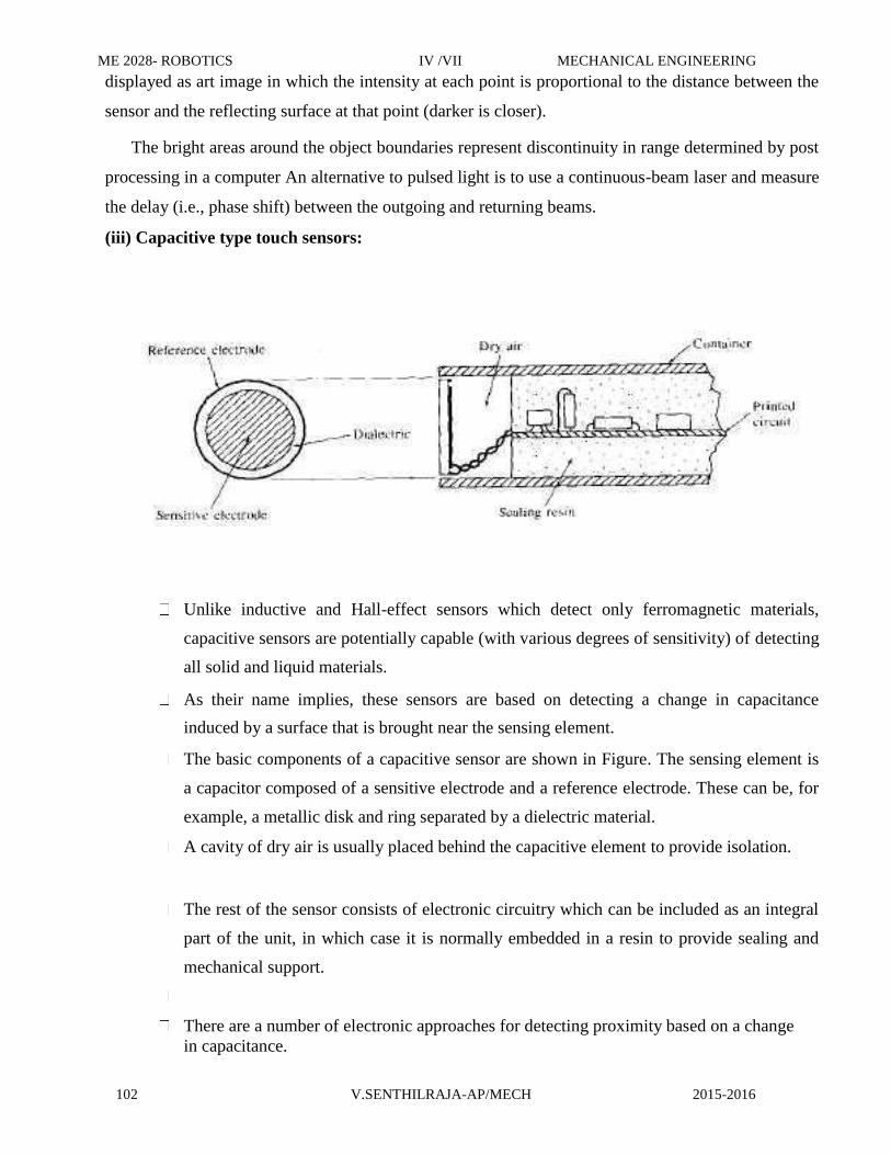
ME 2028- ROBOTICS IV /VII MECHANICAL ENGINEERING
102 V.SENTHILRAJA-AP/MECH 2015-2016
displayed as art image in which the intensity at each point is proportional to the distance between the
sensor and the reflecting surface at that point (darker is closer).
The bright areas around the object boundaries represent discontinuity in range determined by post
processing in a computer An alternative to pulsed light is to use a continuous-beam laser and measure
the delay (i.e., phase shift) between the outgoing and returning beams. (iii) Capacitive type touch sensors:
Unlike inductive and Hall-effect sensors which detect only ferromagnetic materials,
capacitive sensors are potentially capable (with various degrees of sensitivity) of detecting
all solid and liquid materials.
As their name implies, these sensors are based on detecting a change in capacitance
induced by a surface that is brought near the sensing element.
The basic components of a capacitive sensor are shown in Figure. The sensing element is
a capacitor composed of a sensitive electrode and a reference electrode. These can be, for
example, a metallic disk and ring separated by a dielectric material.
A cavity of dry air is usually placed behind the capacitive element to provide isolation.
The rest of the sensor consists of electronic circuitry which can be included as an integral
part of the unit, in which case it is normally embedded in a resin to provide sealing and
mechanical support.
There are a number of electronic approaches for detecting proximity based on a change
in capacitance.
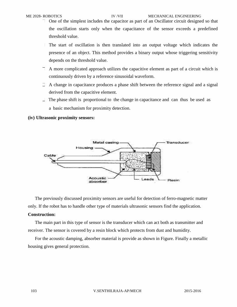
ME 2028- ROBOTICS IV /VII MECHANICAL ENGINEERING
103 V.SENTHILRAJA-AP/MECH 2015-2016
One of the simplest includes the capacitor as part of an Oscillator circuit designed so that
the oscillation starts only when the capacitance of the sensor exceeds a predefined
threshold value.
The start of oscillation is then translated into an output voltage which indicates the
presence of an object. This method provides a binary output whose triggering sensitivity
depends on the threshold value.
A more complicated approach utilizes the capacitive element as part of a circuit which is
continuously driven by a reference sinusoidal waveform.
A change in capacitance produces a phase shift between the reference signal and a signal
derived from the capacitive element.
The phase shift is proportional to the change in capacitance and can thus be used as
a basic mechanism for proximity detection. (iv) Ultrasonic proximity sensors:
The previously discussed proximity sensors are useful for detection of ferro-magnetic matter
only. If the robot has to handle other type of materials ultrasonic sensors find the application. Construction:
The main part in this type of sensor is the transducer which can act both as transmitter and
receiver. The sensor is covered by a resin block which protects from dust and humidity.
For the acoustic damping, absorber material is provide as shown in Figure. Finally a metallic
housing gives general protection.

ME 2028- ROBOTICS IV /VII MECHANICAL ENGINEERING
104 V.SENTHILRAJA-AP/MECH 2015-2016
UNIT IV
Robot kinematics and Robot Programming
Part-A
1. Methods of robot programming? Nov/Dec2010
Lead through methods
Textual robot languages
Mechanical Programming 2. Ways of accomplishing lead through programming? Nov/Dec2012
Powered Lead through
Manual Lead through
3. Teach pendant. Apr/May2009
The teach pendant is usually a small handheld control box with combinations of toggle
switches,
dials and buttons to regulate the robot‘s physical movements and program capabilities. 4. Methods of teaching. Nov/Dec 2011
Joint movements
X-Y-Z coordinates motions
Tool coordinate motions
5. Types of Robot kinematics. Nov/Dec2009
Forward kinematics
It is a scheme to determine joint angles of a robot by knowing its position in the world
coordinate system.
Reverse kinematics
It is a scheme to determine the position of the robot in the world coordinate system by
knowing the joint angles and the link parameters of the robot. 6. Define Trajectory planning. Nov/Dec2008
It is defined as planning of the desired movements of the manipulator.
7. Degrees of freedom. Nov/Dec2009,2010 Apr/May2011,2013
The number of independent ways by which a dynamic system can move without violating any
constraint imposed on it, is called degree of freedom. In other words, the degree of freedom

ME 2028- ROBOTICS IV /VII MECHANICAL ENGINEERING
105 V.SENTHILRAJA-AP/MECH 2015-2016
can be defined as the minimum number of independent coordinates which can specify the position
of the system completely. 8. Joint mode of teaching robots. Nov/Dec2013
The teach pendant has a set of toggle switches (or similar controlled devices) operate each
joint either of it to directions until the endeffector has been positioned to the desired point. 9. Reasons for defining points in a program.
To define a working position for the endeffectors
To avoid obstacles
10. Define Position representation. Nov/Dec2009
The position of the end of the arm may be represented by the two joint angles q1 and q2.this
is known as position representation.
Pj = (q1,q2) 11. What is Servo controlled robots? Nov/Dec2013
Servo controlled robots, which are programmed by lead through an textual language methods
tend to actuate all axes simultaneously. 12. Define Circular Interpolation. May/June 2011
Circular Interpolation requires the programmer to define a circle in the robot‘s
workspace which is
done by specifying three points that lie along the circle. 13. Irregular smooth motions? Apr/May2007
The segments in manual lead though programming are sometimes approximately straight
sometimes curved and sometimes back and forth motions. These motions are called irregular
smooth motions. 14. Manual lead through programming? Nov/Dec2007
In manual lead through programming the programmer moves the manipulated wrist to teach
spray-painting or arc welding. The movements consist of combination of smooth motion
segments.
Part-B (16 Marks)

ME 2028- ROBOTICS IV /VII MECHANICAL ENGINEERING
106 V.SENTHILRAJA-AP/MECH 2015-2016
1. Explain Robot Programming Languages in detail. Nov/Dec2013
Robot languages have been developed for ease of control of motions of robots having
different structures and geometrical capabilities.
Some of the robot languages have been developed by modifying the existing general-
purpose computer languages and some of them are written in a completely new style.
Programming languages have been developed by the pioneer efforts of various
researchers at Stanford Artificial Intelligence Laboratory; research laboratories of
IBM Corporation, under U.S. Air Force sponsorship, General Electric Co., Unimation
and many other robot manufacturers.
WAVE and AL:
WAVE, developed at Stanford, demonstrated a robot hand—eye coordination
while it was implemented in a machine vision system.
Later a powerful language AL was developed to control robot arms. WAVE
incorporated many important features.
Trajectory calculations through coordination of joint movements, end-effector
positions and touch sensing were some of the new features of WAVE. But the
algorithm was too complex and not userfriendly.
They could not be run in real-time and on-line. On the other hand, trajectory
calculations are
possible at compile time and they can be modified during run time.
AML:
A manufacturing language, AML was developed by IBM. AML is very useful for
assembly operations as different user—robot programming interfaces are possible.
The programming language AML is also used in other automated
manufacturing systems.
The advantage of using AML is that integers, real numbers and strings can be
specified in the same aggregate which is said to be an ordered set of constants
or variables.
MCL:
US Air force ICAM project led to the development of another manufacturing
control language known as MCL by McDonnel—Douglas.
This is a modification of the popular APT (Automatically Programmed Tooling)
language used in CNC machine tools as many similar commands are used to control

ME 2028- ROBOTICS IV /VII MECHANICAL ENGINEERING
107 V.SENTHILRAJA-AP/MECH 2015-2016
machine tools in CAM applications. RAIL:
was developed by Automatic for robotic assembly, inspection, arc
welding and machine vision. A variety of data types as used in PASCAL can be
used.
It
uses Motorola 68000 type microcomputer system; It supports many commands and
control of the vision system. HELP:
HELP was developed by General Electric Company. It acts more or less like
RAIL.
It has the capability to control two robot arms at the same time. The structure
of the language is like PASCAL. JARS:
JARS was developed by NASA JPL. The base of the language is PASCAL. JARS can
be interfaced with PUMA 6000 robot for running robotic programs. RPL:
RPL was developed at SRI International. A compiler is used to convert a program into the
codes that can be interpreted by an interpreter. Unimation PUMA 500 can be controlled with
the help of RPL. The basic ideas of LISP (an Al language) have been organized into a
FORTRAN-like syntax in RPL. It is modular and flexible.
Besides these, there are some other languages like PAL, ADA etc. PAL has been written by
Richard Paul by modifying WAVE and incorporating features of PASCAL. But the
representations of syntaxes used in the program are difficult to handle. ADA developed by the
Department of Defense (DOD) in USA is a real-time system that can be run on several
microcomputers like Zilog, VAX, Motorola 68000, etc. ADA is convenient for controlling the
robots used in a manufacturing cell.
Different textual robot languages have different attributes. Far example, VAL, HELP and
MC though powerful for many simple tasks, do not have the same structured modular
programming capability like AL, AML, JARS and ADA or VAL II. In a manufacturing cell,
multiple robots or robotic equipment work in unison. Control of two or more operations done
by the robots in a coordinated manner is complex.
Synchronizing the motions of the robots requires necessary software commands. AL, ADA,
AML, MCL have the capability of controlling multiple arms.

ME 2028- ROBOTICS IV /VII MECHANICAL ENGINEERING
108 V.SENTHILRAJA-AP/MECH 2015-2016
The programming language must be capable of expressing various geometric features like
joint angles, coordinate transformations such as rotation, translation, and vector quantities.
Homogeneous matrices are used to specify the rotation. Rotation can also be specified by Euler angles. AML, RAIL and VAL use Euler angles
while AL manipulates homogeneous matrix for control. AL is very suitable for assembly
tasks wherein many sensors are employed, though other languages like AML and HELP are
flexible enough to run various subroutines.
2.Derive the forward and reverse transformation of 2-Degree of freedom and 3- degree
of freedom arm. Apr/May 2011

ME 2028- ROBOTICS IV /VII
MECHANICAL ENGINEERING
109 V.SENTHILRAJA-AP/MECH 2015-2016

ME 2028- ROBOTICS IV /VII MECHANICAL ENGINEERING
110 V.SENTHILRAJA-AP/MECH 2015-2016
Adding Orientation: A 3-Degree of Freedom Arm in (2D) Two Dimension
The arm we have been modeling is very simple; a two-jointed robot arm has little
practical value except for very simple tasks. Let us add to the manipulator a modest capability
for orienting as well as positioning a part or tool. Accordingly, we will incorporate a third
degree of freedom into the previous configuration to develop the RR:R manipulator shown in
Fig. 4-5. This third degree of freedom will represent a wrist joint. The world space
coordinates for the wrist end would
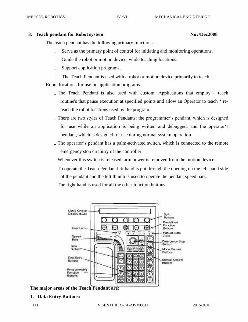
ME 2028- ROBOTICS IV /VII MECHANICAL ENGINEERING
111 V.SENTHILRAJA-AP/MECH 2015-2016
3. Teach pendant for Robot system Nov/Dec2008
The teach pendant has the following primary functions:
Serve as the primary point of control for initiating and monitoring operations.
Guide the robot or motion device, while teaching locations.
Support application programs.
The Teach Pendant is used with a robot or motion device primarily to teach.
Robot locations for use: in application programs.
The Teach Pendant is also used with custom. Applications that employ ―teach
routine's that pause execution at specified points and allow an Operator to teach * re-
teach the robot locations used by the program.
There are two styles of Teach Pendants: the programmer‘s pendant, which is designed
for use while an application is being written and debugged, and the operator‘s
pendant, which is designed for use during normal system operation.
The operator‘s pendant has a palm-activated switch, which is connected to the remote
emergency stop circuitry of the controller.
Whenever this switch is released, arm power is removed from the motion device.
To operate the Teach Pendant left hand is put through the opening on the left-hand side
of the pendant and the left thumb is used to operate the pendant speed bars.
The right hand is used for all the other function buttons. The major areas of the Teach Pendant are: 1. Data Entry Buttons:

ME 2028- ROBOTICS IV /VII MECHANICAL ENGINEERING
112 V.SENTHILRAJA-AP/MECH 2015-2016
The data entry buttons are used to input data, normally in response to prompts that
appear on the pendant display
The data entry buttons include YES/NO, DEL, the numeric buttons, the decimal point
and the REC/DONE button, which behaves like the Return or Enter key on a normal
keyboard. In many cases, application programs have users press the REC/DONE button
to signal that they have completed a task. 2. Emergency Stop Switch:
The emergency stop switch on the Teach Pendant immediately halts program execution and
turns off arm power. 3. User LED:
The pendant is in background mode when the user LED is in not lit and none of the
predefined functions are being used. The user LED is lit whenever an application program is
making use of the Teach Pendant. 4. Mode Control Buttons:
The mode control buttons change the state being used to move the robot, switch control
between the Teach Pendant and the application programs and enable arm power when
necessary. 5. Manual Control Buttons:
When the Teach Pendant is in manual mode, these buttons select which robot joint will
move, or the coordinate axis along which the robot will move. 6. Manual State LEDs:
The manual state LEDs indicates the type of manual motion that has been selected. 7. Speed Bars:
The speed bars are used to control the robot‘s speed and direction. Pressing the speed bar
near the outer ends will move the robot faster, while pressing the speed bar near the center
will move the robot slower. 8. Slow Button:
The slow button selects between the two different speed ranges of the speed bars.
9. Predefined Function Buttons:
The predefined function buttons have specific, system- wide functions assigned to them, like
display of coordinates, clear error, etc. 10. Programmable Function Buttons:
The programmable function buttons are used in custom application programs, and their
functions will vary depending upon the program being run.

ME 2028- ROBOTICS IV /VII MECHANICAL ENGINEERING
113 V.SENTHILRAJA-AP/MECH 2015-2016
11. Soft Buttons:
The ―soft‖ buttons have different functions depending on the application program being run,
or the selection made from the predefined function buttons.
4. Explain the Capabilities and limitations of Lead through methods. Nov/Dec2007
During this programming method, the traveling of robots is based on the desired movements,
and it is stored in the external controller memory.
There are two modes of a control system in this method such as a run mode and teach mode.
The program is taught in the teach mode, and it is executed in the run mode.
The leadthrough programming method can be done by two methods namely:
Powered Leadthrough Method
Manual Leadthrough Method
Powered Leadthrough Method:
The p o w e r e d l e a d t h r o u g h i s the common programming method in the industries.
A teach pendant is incorporated in this method for controlling the motors available in the
joints. It is also used to operate the robot wrist and arm through a sequence of points.
The playback of an operation is done by recording these points. The control of complex
geometric moves is difficult to perform in the teach pendant. As a result, this method is good
for point to point movements.
Some of the key applications are spot welding, machine loading & unloading, and part
transfer process.
Manual Leadthrough Method:
In this method, the robot‘s end effectors is moved physically by the programmer at the
desired movements.
Sometimes, it may be difficult to move large robot arm manually. To get rid of it a teach
button is implemented in the wrist for special programming.
The manual leadthrough method is also known as Walk Through method. It is mainly used to
perform continuous path movements. This method is best for spray painting and arc welding
operations.
Limitation:
Lead through programming is not readily compatible with modern
computer based technology.

ME 2028- ROBOTICS IV /VII MECHANICAL ENGINEERING
114 V.SENTHILRAJA-AP/MECH 2015-2016
Robot cannot be used in production, while it is being programmed.
5.Differentiate forward and inverse kinematics. Nov/Dec2013
Forward kinematics:
The transformation of coordinates of the end-effector point from the joint space to the world
space is known as forward kinematic transformation. Reverse kinematics:
The transformation of coordinates from world space to joint space is known as backward or
reverse kinematic transformation.
Robot Kinematics:
Robot arm kinematics deals with the analytic study of the motion of a robot arm with respect to a
fixed reference coordinate system as a function of time.
The mechanical manipulator can be modelled as an open loop articulated chain with several rigid
links connected in series by either revolute‘ or prismatic‘ joints driven by the actuators.
For a manipulator, (the position and orientation of the end-effector are derived from the given
joint angles and link parameters, the scheme is called the forward kinematics problem.

ME 2028- ROBOTICS IV /VII MECHANICAL ENGINEERING
115 V.SENTHILRAJA-AP/MECH 2015-2016
If, on the other hand, the joint angles and the different configuration of the manipulator are
derived from the position and orientation of the endeffector, the scheme is called the reverse
kinematics problem.
Representing the Position Considering the revolute type of joint only, the position of the end-
effector can be represented by the joint angles, 0 02,...,. 0,, as,
The position of the end-effector can also be defined in world space as,
6. Derive the expression for direct and inverse kinematics of 4 degrees of freedom robot manipulator. May/June 2011
A 4-Degree of Freedom Manipulator in (3D) Three Dimensions:
The configuration of a manipulator in three dimensions. The manipulator has 4 degrees -
of freedom: joint I (type T joint) allows rotation about the z axis; joint 2 (type R) allows
rotation about an axis that is perpendicular to the z axis; joint 3 is a linear joint which is
capable of sliding over a certain range; and joint 4 is a type R joint which allows rotation
about an axis that is parallel to the joint 2 axis. Thus, we have a TRL: R manipulator.

ME 2028- ROBOTICS IV /VII MECHANICAL ENGINEERING
116 V.SENTHILRAJA-AP/MECH 2015-2016
Let us define the angle of rotation of joint I to be the base rotation 0; the angle of rotation of joint 2 will
be called the elevation angle 4.; the length of linear joint 3 will be called the extension L (L-represents a
combination of links 2 and 3); and the angle that joint 4 makes with the x — y plane will be called the pitch
angle 4.
The position of the end of the wrist, P, defined in the world coordinate system for the robot, is given by
7. List the commands used in VAL II programming and describe its functions.Nov/Dec2007

ME 2028- ROBOTICS IV /VII MECHANICAL ENGINEERING
117 V.SENTHILRAJA-AP/MECH 2015-2016
\
UNIT V
Implementation and Robots Economics
Part-A

ME 2028- ROBOTICS IV /VII MECHANICAL ENGINEERING
118 V.SENTHILRAJA-AP/MECH 2015-2016
1. Different types of material handling operation. Nov/Dec2008
Manually operated devices—hand trucks, powered trucks, cranes, monorails and
hoists.
Automated systems—conveyors, AGV‘s.
Miscellaneous systems—industrial robots, transfer mechanisms, elevators,
pipelines, containers, dial indexing tables, etc.
2. Define Gantry Robot? Nov/Dec2013
Cartesian coordinate robots with the horizontal member supported at both ends are
sometimes called Gantry robots. 3. Give four Applications of AGV. Nov/Dec2007,2010,2011
Driverless train operations
Storage distribution system
Assembly line operation
FMS 4. Types of AGV vehicles. Apr/May2009,2011
Towing vehicles
Unit load vehicles
Pallet trucks
Fork trucks
Light load Vehicles
Assembly line vehicles. 5. Differentiate palletizing and depalletizing. Nov/Dec2009
A palletizer or palletiser is a machine which provides automatic means for stacking cases of
goods or products on to a pallet.
A depalletizer machine is any machine that can break down a pallet. Usually, a robot is used
for this task, although there are some other forms of depalletizer that can also break down pallets
and move products from one place to another using simple push bars and conveyor belts.
6. What are the steps to be followed by the company in order to implement robot programs in
its operations? Nov/Dec2007
Initial familiarization with the technology
Plant survey to identify potential applications

ME 2028- ROBOTICS IV /VII MECHANICAL ENGINEERING
119 V.SENTHILRAJA-AP/MECH 2015-2016
Selection of the application
Selection of the robot
Detailed economic analysis and capital authorization
Planning and engineering the installation
Installation 7. Typical technical features required for material transfer. Nov/Dec2009
Number of axes: 3to 5
Control system: limited sequence or point-to-point playback
Drive system: pneumatic or hydraulic
Programming: manual, powered lead through 8. Different methods of economic analysis. Nov/Dec2009,2011
Payback method
Equivalent uniform annual cost (EUAC) method
Return on investment (ROI) method 9. Define ROI method. Apr/May2011
The return on investment method determines the rate of return for the proposed project
based on the estimated cost and revenues. 10. What is EUAC method? Nov/Dec2007
Equivalent uniform annual cost (EUAC) method converts all of the present and future
investments and cash flows into their equivalent uniform cash flows over the anticipated life
of the project. 11. Define Deadman switch. Nov/Dec2009,2011
A dead man switch is a useful control feature during lead through programming. It is a
trigger or toggle switch device generally located on the teach pendant which requires active
pressure to be applied tom the devices in order to drive the manipulator.

ME 2028- ROBOTICS IV /VII MECHANICAL ENGINEERING
120 V.SENTHILRAJA-AP/MECH 2015-2016
12. What are the general characteristics that make potential robot application technically practical
and economically feasible?
1) Hazardous or uncomfortable working conditions
2) Repetitive operations
3) Difficult handling jobs
4) Multicast operation
Part-B (16 Marks) 1. AGV & RGV types of robots. Nov/Dec2013
Automated Guided Vehicles:
An AGV is a computer controlled, driverless vehicle used for transporting materials from point-to-
point in a manufacturing setting.
They represent a major category of automated materials handling devices. They are guided along
defined pathways in the floor.
The vehicles are powered by means of on-board batteries that allow operation for several hours
between recharging.
The definition of the pathways is generally accomplished using wire embedded in the floor or
reflective paint on the floor surface. Guidance is achieved by sensors on the vehicles that can follow the
guide wires or paint.
When it arrives at the proper destination, the material is off loaded onto another conveyor or the
workstation. The vehicle is then dispatched to the next location or to home to await further orders. A
computer controls its motion.
The key terms in AGV are Guide path — The term guide path refers to the actual path the AGV
follows in making its rounds through manufacturing plant. The guide path may be of the

ME 2028- ROBOTICS IV /VII MECHANICAL ENGINEERING
121 V.SENTHILRAJA-AP/MECH 2015-2016
embedded wire type or optical devices.
Routing — It is the ability of the AGV to make decisions that allow it to select the
appropriate route as it moves across the shop floor.
Towing vehicles
These are the most widely used type of AG V‘s and are called the work horse. They are most
commonly used for transporting large amounts of bulky and heavy materials
from the warehouse to various locations in the manufacturing plant, e.g. driverless train Unit load vehicles
They are used in settings with short guide paths, high volume, and need for independent movement
and versatility. Warehouses and distribution centres are the most likely settings for these vehicles. They can
operate in an environment where there is not much room and movement is restricted. Rail Guided Vehicles:
Motorised vehicles that are guided by a fixed rail system constitute a third category of material
transport systems.
If the system uses just one rail it is called a monorail system; whereas it can also consist of a two-rail
system. Monorails typically operate from a suspended position overhead, while two-rail systems are
generally found on the plant floor.
Vehicles operate asynchronously and are driven by an on-board electric motor, with power being
supplied by an electrified rail. This removes the necessity of stoppages owing to battery-power wear-out, as
with AGVs, but it presents a new safety hazard in the form of the electrified rail.
Routing variations are possible in rail systems through a combination of turntables, switches, and other
specialised track sections. This allows different loads to travel different routes, in a similar manner to an
AGVS.

ME 2028- ROBOTICS IV /VII MECHANICAL ENGINEERING
122 V.SENTHILRAJA-AP/MECH 2015-2016
Sorting Transfer Vehicle (STV) is a fast, flexible and easily installed material transport system. STVs
can be used to move loads of all sizes in a warehouse.
STV features sorting and collecting capabilities for multiple AS/RS aisle conveyor stations. It
enables picking by order line and sorting by destination to one.
The STV track can be arranged in a loop or straight line to accommodate a variety of applications, such
as mixed SKU pallet picking, cycle counting, quality inspection, load sorting and truck loading.
Advantages of STVs include: fewer motors, no single point of failure, high-speed, high- throughput and expansion flexibility to handle future growth.
2. Elaborate Economic analysis of Robots . Nov/Dec2009
In addition to the technological considerations involved in applications engineering for a
robotics project, there is also the economic issue.
Will the robot justify itself economically? The economic analysis for any proposed engineering
project is of considerable importance in most companies because management
usually decides whether to install the project on the basis of this analysis.
To perform the economic analysis of a proposed robot project, certain basic information is needed
about the project. This information includes the type of project being considered, the cost of the robot
installation, the production cycle time, and the savings and
benefits resulting from the project.
Type of Robot Installation:
There are two basic categories of robot installations that are commonly encountered. The
first involves a new application. This is where there is no existing facility.
The second situation is the robot installation to replace a current method of operation.
The present method typically involves a production operation that is performed
manually, and the robot would be used somehow to substitute for the human labor.
In either of these situations, certain basic cost information is needed in order to perform the
economic analysis.
The following subsection discusses the kinds of cost and operating data that are used to analyze the
alternative investment projects.
Cost Data Required for the Analysis
The cost data required to perform the economic analysis of a robot project divide into two types:
investment costs and operating costs.
Investment costs:
1. Robot purchase cost—The basic price of the robot equipped from the manufacturer with the

ME 2028- ROBOTICS IV /VII MECHANICAL ENGINEERING
123 V.SENTHILRAJA-AP/MECH 2015-2016
proper options (excluding end effector) to perform the application.
2. Engineering costs— The costs of planning and design by the user company‘s
engineering staff to install the robot.
3. Installation costs— This includes the labor and materials needed to prepare the
installation site (provision for utilities, floor preparation, etc.).
4. Special tooling— This includes the cost of the end eflector, parts position and other
fixtures and tools required to operate the work cell,
5. Miscellaneous costs—This covers the additional investment costs not included by any
of the above categories (e.g., other equipment needed for the cell). Operating costs and savings: 6. Direct labor cost—The direct labor cost associated with the operation of the robot cell.
Fringe benefits are usually included in the calculation of direct labor rate, but other
overhead costs are excluded. 7. Indirect labor cost—The indirect labor costs that can be directly allocated to thc operation
of the robot cell. These costs include supervision, setup, programming, and other personnel
costs not included in category 6 above 8. Maintenance—This covers the anticipated costs of maintenance and repair for the robot cell.
These costs are included under this separate heading rather than in category 7 because the
maintenance costs involve not only indirect labor (the maintenance crew) but also materials
(replacement parts) and service calls by the robot manufacturer. A reasonable ‗rule of thumb‖ in the absence of better data is that the annual maintenance cost for she
robot will be approximately 10 percent of the purchase price (category I).
9. Utilities—this includes the cost of utilities to operate the robot cell (e.g., electricity,
air pressure, gas). These are usually minor costs compared to the above items.
10. Training—Training might be considered to be an investment cost because much of
the training required for the installation will occur as a first cost of the installation.
However, training should he a continuing activity, and so it is included as an operating cost.

ME 2028- ROBOTICS IV /VII MECHANICAL ENGINEERING
124 V.SENTHILRAJA-AP/MECH 2015-2016
3. Explain about Safety sensors and safety monitoring of Robots. Nov/Dec2009

ME 2028- ROBOTICS IV /VII
MECHANICAL ENGINEERING
125 V.SENTHILRAJA-AP/MECH 2015-2016

ME 2028- ROBOTICS IV /VII
MECHANICAL ENGINEERING
126 V.SENTHILRAJA-AP/MECH 2015-2016
4. Various steps involved for implementing the robot in industries. Nov/Dec2011 5. Economic analysis of industrial robots. Apr/May 2013

ME 2028 ROBOTICS VII/IV MECHANICAL ENGINEERING
127 V.SENTHILRAJA AP/MECH 2015-2016