a cracking good story about liquid metal … · a cracking good story about liquid metal...
TRANSCRIPT
www.voestalpine.com
WHITE PAPER
Robert Sierlinger, Martin Gruber, voestalpine Stahl GmbH
A CRACKING GOOD STORY ABOUT LIQUID METAL EMBRITTLEMENT DURING SPOT WELDING OF
ADVANCED HIGH STRENGTH STEELS
www.voestalpine.com
WHITE PAPER
INHALT
03 Abstract
04 01. Introduction
06 02. Attempting to distinguish the LME sensitivity
of zinc coated steels
06 02.01. Experimental
08 02.02. Results & Discussion
14 03. Attempting to avoid LME during spot
welding of zinc coated steels
14 03.01. Experimental
16 04. Summary
www.voestalpine.com
WHITE PAPER
ABSTRACTAdvanced high strength steels (AHSS), mainly dual-phase and complex-phase steels, havebeen introduced to vehicle manufacturing successfully in the past fifteen years. Nowadaystensile strength levels from 600 to 1200 MPa are covered. Current developments are aimingat increasing the formability at a certain strength level. These steels are called “AdvancedHigh Strength Steels with High Ductility (AHSS HD)”.
In general the suitability for spot welding, which always is a major objective duringdevelopment, is determined by the amount of alloying elements on the one hand and by thetype of coating, mainly alloys of zinc in case of steel, on the other hand. Improving strengthand forming properties has been linked to continuously increasing alloying content of AHSSin comparison to low alloyed mild and conventional high strength steels. The combination ofhigher alloying content and the occurence of liquid zinc, which is an inevitable consequencedue to the heat generation during spot welding, and tensions during welding can lead toliquid metal embrittlement (LME), as the zinc is able to penetrate the grain boundaries ofthe steel in the heat affected zone of the spot weld.
In addition to the material and surface aspects the occurrence of LME furthermore depends on the spot welding situation itself, including number and thickness of sheets, welding machine, electrode caps, tensions during welding, overall heat input and also misfits during welding.
This paper gives an overview about the susceptibility of advanced high strength steels to liquid metal embrittlement and possible countermeasures during spot welding. Spot welding has been performed with a wide range of AHSS using the same pedestal type 1000Hz-MFDC welding machine applying comparable conditions with respect to the welding environment used.
3

www.voestalpine.com
WHITE PAPER
01 IntroductionSuitability for spot welding is the major development aspect of advanced high strengthsteels in the field of joining, because spot welding is and will remain the primary joiningprocess in steel intense car body manufacturing. In Europe most of the development work is done referring to Stahl-Eisen-Prüfblatt 1220-Part 2 (SEP1220-2), which describes a practicalprocedure for the determination of the suitability of steel sheet for the spot weldingprocess.
Usually a similar two-sheet combination of the desired steel is being welded usingparameters in step with actual practice. The suitability for spot welding is then described bydetermination of welding current range, electrode life, bearable loads and fracture types forvarious load types, e.g. tensile shear and cross tension load. Additionally metallographyincluding hardness testing is carried out.
In welding thin steel sheet the use of zinc based coatings for corrosion protection is one ofthe major factors determining suitability for welding. Zinc based coatings generally lead to adegradation of steel´s suitability for spot welding. On the one hand electrode life is loweredin comparison to uncoated steel and on the other hand zinc can be observed penetrating thegrain boundaries of the steel in the heat affected zone of the spot weld inducing brittlefracture by LME. LME has accompanied the spot welders since zinc coatings on steel sheetshave been used from corrosion protection reasons.
LME develops due to the intrusion of liquid zinc into the steel sheet along the grainboundaries of a sensitive material under the impact of tensions from the spot weldingelectrode being pressed onto the steel surface (Figure 1).
4
2
2. Introduction
Suitability for spot welding is the major development aspect of advanced high strengthsteels in the field of joining, because spot welding is and will remain the primary joiningprocess in steel intense car body manufacturing. In Europe most of the development work isdone referring to Stahl-Eisen-Prüfblatt 1220-Part 2 (SEP1220-2), which describes a practicalprocedure for the determination of the suitability of steel sheet for the spot weldingprocess.
Usually a similar two sheet combination of the desired steel is being welded usingparameters in step with actual practice. The suitability for spot welding is then described bydetermination of welding current range, electrode life, bearable loads and fracture types forvarious load types, e.g. tensile shear and cross tension load. Additionally metallographyincluding hardness testing is carried out.
In welding thin steel sheet the use of zinc based coatings for corrosion protection is one ofthe major factors determining suitability for welding. Zinc based coatings generally lead to adegradation of steel´s suitability for spot welding. On the one hand electrode life is loweredin comparison to uncoated steel and on the other hand zinc can be observed penetrating thegrain boundaries of the steel in the heat affected zone of the spot weld inducing brittlefracture by LME. LME has accompanied the spot welders since zinc coatings on steel sheetshave been used from corrosion protection reasons.
LME develops due to the intrusion of liquid zinc into the steel sheet along the grainboundaries of a sensitive material under the impact of tensions from the spot weldingelectrode being pressed onto the steel surface (Figure 1).
Figure 1: Conditions for the occurence of LME
Hence the occurrence of LME is closely linked to the chemical composition, structure andmetallic coating of the steel, as well as to the spot welding situation, e.g. type of electrode,welding current and overall heat input.
Figure 1: Conditions for the occurence of LME
Hence the occurrence of LME is closely linked to the chemical composition, structure andmetallic coating of the steel, as well as to the spot welding situation, e.g. type of electrode,welding current and overall heat input.
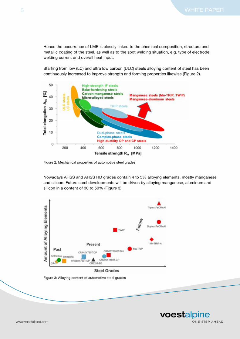
Starting from low (LC) and ultra low carbon (ULC) steels alloying content of steel has beencontinuously increased to improve strength and forming properties likewise (Figure 2).
Nowadays AHSS and AHSS HD grades contain 4 to 5% alloying elements, mostly manganeseand silicon. Future steel developments will be driven by alloying manganese, aluminum andsilicon in a content of 30 to 50% (Figure 3).
www.voestalpine.com
WHITE PAPER5
Figure 2: Mechanical properties of automotive steel grades
3
Starting from low (LC) and ultra low carbon (ULC) steels alloying content of steel has beencontinuously increased to improve strength and forming properties likewise (Figure 2).
Figure 2: Mechanical properties of automotive steel grades
Nowadays AHSS and AHSS HD grades contain 4 to 5 % alloying elements, mostly manganeseand silicon. Future steel developments will be driven by alloying manganese, aluminum andsilicon in a content of 30 to 50 % (Figure 3).
Figure 3: Alloying content of automotive steel grades
The mentioned elements, manganese, silicon and aluminum are known to be essential forfulfilling mechanical properties and at the same time especially for increasing the electricalresistance of the steel significantly. This leads to higher heat generation in possibly LMEcritical regions of the spot weld. In combination with higher tensions during spot welding inthese regions due to the higher strength of the steel, also at elevated temperatures, the LMErisk is increased in comparison to lower alloyed steels.
Figure 3: Alloying content of automotive steel grades
www.voestalpine.com
WHITE PAPER6
The mentioned elements, manganese, silicon and aluminum are known to be essential forfulfilling mechanical properties and at the same time especially for increasing the electricalresistance of the steel significantly. This leads to higher heat generation in possibly LME-critical regions of the spot weld. In combination with higher tensions during spot welding inthese regions due to the higher strength of the steel, also at elevated temperatures, the LMErisk is increased in comparison to lower alloyed steels.
Again manganese and silicon are to be mentioned in this context, as both elements deliveran important contribution to solid solution strengthening of the steel, also at elevatedtemperatures.
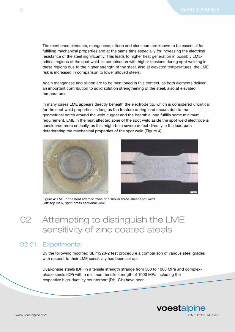
In many cases LME appears directly beneath the electrode tip, which is considered uncriticalfor the spot weld properties as long as the fracture during load occurs due to thegeometrical notch around the weld nugget and the bearable load fulfills some minimumrequirement. LME in the heat affected zone of the spot weld aside the spot weld electrode isconsidered more critically, as this might be a severe defect directly in the load pathdeteriorating the mechanical properties of the spot weld (Figure 4).
4
Again manganese and silicon are to be mentioned in this context, as both elements deliveran important contribution to solid solution strengthening of the steel, also at elevatedtemperatures.
In many cases LME appears directly beneath the electrode tip, which is considered uncriticalfor the spot weld properties as long as the fracture during load occurs due to thegeometrical notch around the weld nugget and the bearable load fulfills some minimumrequirement. LME in the heat affected zone of the spot weld aside the spot weld electrode isconsidered more critically, as this might be a severe defect directly in the load pathdeteriorating the mechanical properties of the spot weld (Figure 4).
Figure 4: LME in the heat affected zone of a similar three sheet spot weld(left: top view, right: cross sectional view)
3. Attempting to distinguish the LME sensitivity of zinc coated steels
3.1. Experimental
By the following modified SEP1220-2 test procedure a comparison of various steel gradeswith respect to their LME sensitivity has been set up.
Dual phase steels (DP) in a tensile strength strange from 500 to 1000 MPa andcomplex phase steels (CP) with a minimum tensile strength of 1000 MPa including therespective high ductility counterpart (DH, CH) have been investigated, additionally micro-alloyed steel (LA) and TRIP-steel have been included.
Steel sheets have been either electrolytically galvanized (EG) or hot dip galvanized (GI) in athickness range from 1.0 to 1.6 mm.
In the first step the maximum welding current (Imax) has been determined for a similartwo sheet combination of each steel grade strictly as described in SEP1220-2. Therefore a1000 Hz-MFDC-pedestal type welder has been used applying single-pulse welding withconstant current regulation. Electrode has been chosen F1-16-20-6 (CuCrZr).
Figure 4: LME in the heat affected zone of a similar three-sheet spot weld(left: top view, right: cross sectional view)
02 Attempting to distinguish the LME sensitivity of zinc coated steels
02.01. ExperimentalBy the following modified SEP1220-2 test procedure a comparison of various steel gradeswith respect to their LME sensitivity has been set up.
Dual-phase steels (DP) in a tensile strength strange from 500 to 1000 MPa and complex- phase steels (CP) with a minimum tensile strength of 1000 MPa including therespective high-ductility counterpart (DH, CH) have been

investigated, additionally microalloyed steel (LA) and TRIP steel have been included.
Steel sheets have been either electrolytically galvanized (EG) or hot dip galvanized (GI) in athickness range from 1.0 to 1.6 mm.
In the first step the maximum welding current (Imax) has been determined for a similartwo-sheet combination of each steel grade strictly as described in SEP1220-2. Therefore a1000 Hz-MFDC-pedestal type welder has been used applying single-pulse welding withconstant current regulation. Electrode has been chosen F1-16-20-6 (CuCrZr).
In the second step a similar three-sheet combination has been welded for the LMEcomparison using the afore determined Imax of the similar two-sheet combination. Electrodeforce and weld time of the two-sheet combination have been applied also for the three-sheet combination.
Occurrence of LME in the heat affected zone has then been provoked by increasing the heatinput in the three-sheet combination through application of long time welding using doubledand quintupled welding time at a constant welding current Imax.
As can be seen in Figure 6, which is a magnification of Figure 5, even with suitable heat inputLME can be observed starting to penetrate into a sensitive steel grade.
www.voestalpine.com
WHITE PAPER7
5
In the second step a similar three sheet combination has been welded for the LMEcomparison using the afore determined Imax of the similar two sheet combination. Electrodeforce and weld time of the two sheet combination have been applied also for the threesheet combination.
Occurrence of LME in the heat affected zone has then been provoked by increasing the heatinput in the three sheet combination through application of long time welding using doubledand quintupled welding time at a constant welding current Imax.
As can be seen in Figure 6, which is a magnification of Figure 5, even with suitable heat inputLME can be observed starting to penetrate into a sensitive steel grade.
Figure 5: Similar three sheet spot weld withsuitable heat input (single weld time)
Figure 6: Similar three sheet spot weld withsuitable heat input (single weld time)
Figure 7 and Figure 8 show that increasing the heat input by extending the weld time causesLME with corresponding depth up to single sheet thickness.
Figure 7: Similar three sheet spot weld withincreased heat input (double weld time)
Figure 8: Similar three sheet spot weld withexcessive heat input (quintupled weld time)
8 spots have been welded at each weld time setting. Afterwards the number of spot weldsaffected by LME and the depth of LME have been evaluated. This has been done by visualtesting including the use of a microscope and subsequent metallography.
5
In the second step a similar three sheet combination has been welded for the LMEcomparison using the afore determined Imax of the similar two sheet combination. Electrodeforce and weld time of the two sheet combination have been applied also for the threesheet combination.
Occurrence of LME in the heat affected zone has then been provoked by increasing the heatinput in the three sheet combination through application of long time welding using doubledand quintupled welding time at a constant welding current Imax.
As can be seen in Figure 6, which is a magnification of Figure 5, even with suitable heat inputLME can be observed starting to penetrate into a sensitive steel grade.
Figure 5: Similar three sheet spot weld withsuitable heat input (single weld time)
Figure 6: Similar three sheet spot weld withsuitable heat input (single weld time)
Figure 7 and Figure 8 show that increasing the heat input by extending the weld time causesLME with corresponding depth up to single sheet thickness.
Figure 7: Similar three sheet spot weld withincreased heat input (double weld time)
Figure 8: Similar three sheet spot weld withexcessive heat input (quintupled weld time)
8 spots have been welded at each weld time setting. Afterwards the number of spot weldsaffected by LME and the depth of LME have been evaluated. This has been done by visualtesting including the use of a microscope and subsequent metallography. 5
In the second step a similar three sheet combination has been welded for the LMEcomparison using the afore determined Imax of the similar two sheet combination. Electrodeforce and weld time of the two sheet combination have been applied also for the threesheet combination.
Occurrence of LME in the heat affected zone has then been provoked by increasing the heatinput in the three sheet combination through application of long time welding using doubledand quintupled welding time at a constant welding current Imax.
As can be seen in Figure 6, which is a magnification of Figure 5, even with suitable heat inputLME can be observed starting to penetrate into a sensitive steel grade.
Figure 5: Similar three sheet spot weld withsuitable heat input (single weld time)
Figure 6: Similar three sheet spot weld withsuitable heat input (single weld time)
Figure 7 and Figure 8 show that increasing the heat input by extending the weld time causesLME with corresponding depth up to single sheet thickness.
Figure 7: Similar three sheet spot weld withincreased heat input (double weld time)
Figure 8: Similar three sheet spot weld withexcessive heat input (quintupled weld time)
8 spots have been welded at each weld time setting. Afterwards the number of spot weldsaffected by LME and the depth of LME have been evaluated. This has been done by visualtesting including the use of a microscope and subsequent metallography.
5
In the second step a similar three sheet combination has been welded for the LMEcomparison using the afore determined Imax of the similar two sheet combination. Electrodeforce and weld time of the two sheet combination have been applied also for the threesheet combination.
Occurrence of LME in the heat affected zone has then been provoked by increasing the heatinput in the three sheet combination through application of long time welding using doubledand quintupled welding time at a constant welding current Imax.
As can be seen in Figure 6, which is a magnification of Figure 5, even with suitable heat inputLME can be observed starting to penetrate into a sensitive steel grade.
Figure 5: Similar three sheet spot weld withsuitable heat input (single weld time)
Figure 6: Similar three sheet spot weld withsuitable heat input (single weld time)
Figure 7 and Figure 8 show that increasing the heat input by extending the weld time causesLME with corresponding depth up to single sheet thickness.
Figure 7: Similar three sheet spot weld withincreased heat input (double weld time)
Figure 8: Similar three sheet spot weld withexcessive heat input (quintupled weld time)
8 spots have been welded at each weld time setting. Afterwards the number of spot weldsaffected by LME and the depth of LME have been evaluated. This has been done by visualtesting including the use of a microscope and subsequent metallography.
Figure 5: Similar three-sheet spot weld withsuitable heat input (single weld time)
Figure 6: Similar three-sheet spot weld withsuitable heat input (single weld time)
Figure 7: Similar three-sheet spot weld withincreased heat input (double weld time)
Figure 8: Similar three-sheet spot weld withexcessive heat input (quintupled weld time)
www.voestalpine.com
WHITE PAPER8
8 spots have been welded at each weld time setting. Afterwards the number of spot weldsaffected by LME and the depth of LME have been evaluated. This has been done by visualtesting including the use of a microscope and subsequent metallography.
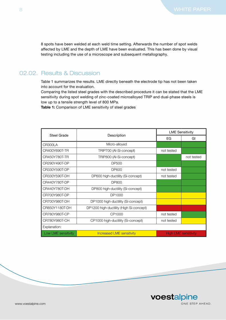
02.02. Results & DiscussionTable 1 summarizes the results. LME directly beneath the electrode tip has not been takeninto account for the evaluation.Comparing the listed steel grades with the described procedure it can be stated that the LMEsensitivity during spot welding of zinc-coated microalloyed TRIP and dual-phase steels islow up to a tensile strength level of 800 MPa.Table 1: Comparison of LME sensitivity of steel grades
Steel Grade DescriptionLME Sensitivity
EG GI
CR300LA Micro-alloyed
CR400Y690T-TR TRIP700 (Al-Si-concept) not tested
CR450Y780T-TR TRIP800 (Al-Si-concept) not tested
CR290Y490T-DP DP500
CR330Y590T-DP DP600 not tested
CR330Y590T-DH DP600 high-ductility (Si-concept) not tested
CR440Y780T-DP DP800
CR440Y780T-DH DP800 high-ductility (Si-concept)
CR700Y980T-DP DP1000
CR700Y980T-DH DP1000 high-ductility (Si-concept)
CR850Y1180T-DH DP1200 high-ductility (High Si-concept)
CR780Y980T-CP CP1000 not tested
CR780Y980T-CH CP1000 high-ductility (Si-concept) not tested
Explanation:
Low LME sensitivity Increased LME sensitivity High LME sensitivity
www.voestalpine.com
WHITE PAPER9
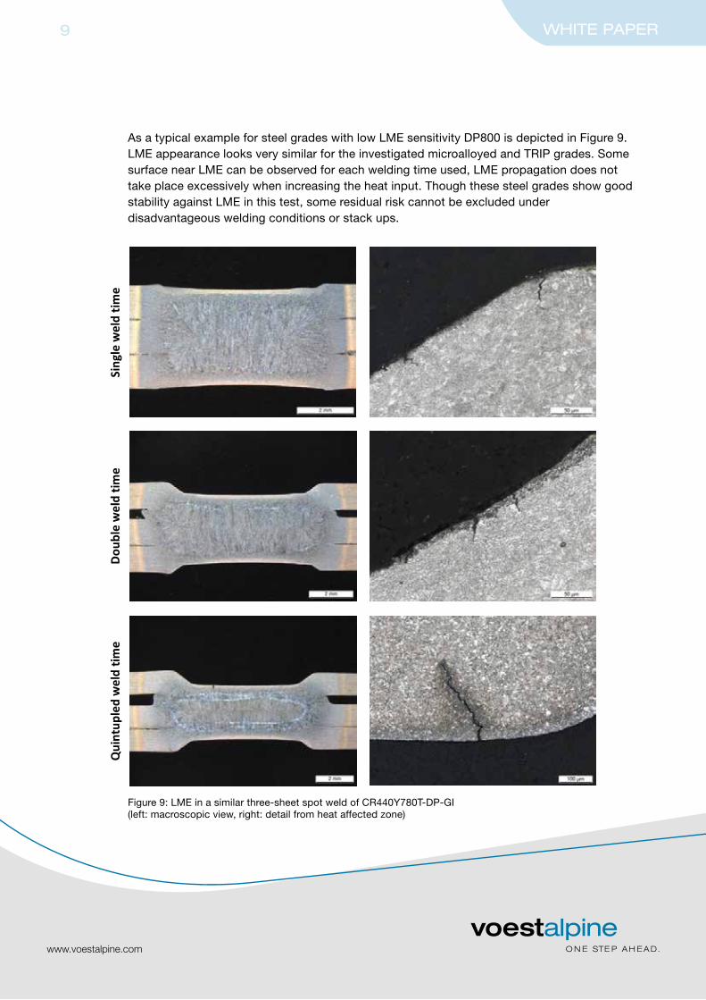
As a typical example for steel grades with low LME sensitivity DP800 is depicted in Figure 9.LME appearance looks very similar for the investigated microalloyed and TRIP grades. Somesurface near LME can be observed for each welding time used, LME propagation does nottake place excessively when increasing the heat input. Though these steel grades show goodstability against LME in this test, some residual risk cannot be excluded underdisadvantageous welding conditions or stack ups.
7
As a typical example for steel grades with low LME sensitivity DP800 is depicted in Figure 9.LME appearance looks very similar for the investigated micro-alloyed and TRIP-grades. Somesurface near LME can be observed for each welding time used, LME propagation does nottake place excessively when increasing the heat input. Though these steel grades show goodstability against LME in this test, some residual risk cannot be excluded underdisadvantageous welding conditions or stack ups.
Sing
lew
eld
time
Dou
ble
wel
dtim
eQ
uint
uple
dw
eld
time
Figure 9: LME in a similar three sheet spot weld of CR440Y780T-DP-GI(left: macroscopic view, right: detail from heat affected zone)
Figure 9: LME in a similar three-sheet spot weld of CR440Y780T-DP-GI(left: macroscopic view, right: detail from heat affected zone)

www.voestalpine.com
WHITE PAPER10
Increased LME sensitivity can be observed with dual-phase steels starting at a tensilestrength level of 1000 MPa, where LME starts propagating at double weld time resulting in a30 to 50% penetration of the sheet thickness at extended weld times (Figure 10). Almost50% of the welded spots are affected by LME.
8
Increased LME sensitivity can be observed with dual phase steels starting at a tensilestrength level of 1000 MPa, where LME starts propagating at double weld time resulting in a30 to 50 % penetration of the sheet thickness at extended weld times (Figure 10). Almost50 % of the welded spots are affected by LME.
Sing
lew
eld
time
Dou
ble
wel
dtim
eQ
uint
uple
dw
eld
time
Figure 10: LME in a similar three sheet spot weld of CR700Y980T-DP-GI(left: macroscopic view, right: detail from heat affected zone)
Figure 10: LME in a similar three-sheet spot weld of CR700Y980T-DP-GI(left: macroscopic view, right: detail from heat affected zone)
9
Especially the highly silicon alloyed DP1200 high ductility is noticeable due to LMEpenetrating nearly the entire sheet thickness (Figure 11). In case of DP1200 high ductilitymore than 50 % of the welded spots were affected by LME, which besides the LME depthcould be used for distinguishing from DP1000, where less than 50 % of the spots wereaffected.
Comparing DP1000 with its high ductility counterpart and DP1200 high ductility theobservable increase of LME sensitivity can most probably be linked to an increasing amountof silicon, which is the major distinguishing factor inbetween these steel grades.
Sing
lew
eld
time
Dou
ble
wel
dtim
eQ
uint
uple
dw
eld
time
Figure 11: LME in a similar three sheet spot weld of CR850Y1180T-DH-EG(left: macroscopic view, right: detail from heat affected zone)
www.voestalpine.com
WHITE PAPER11
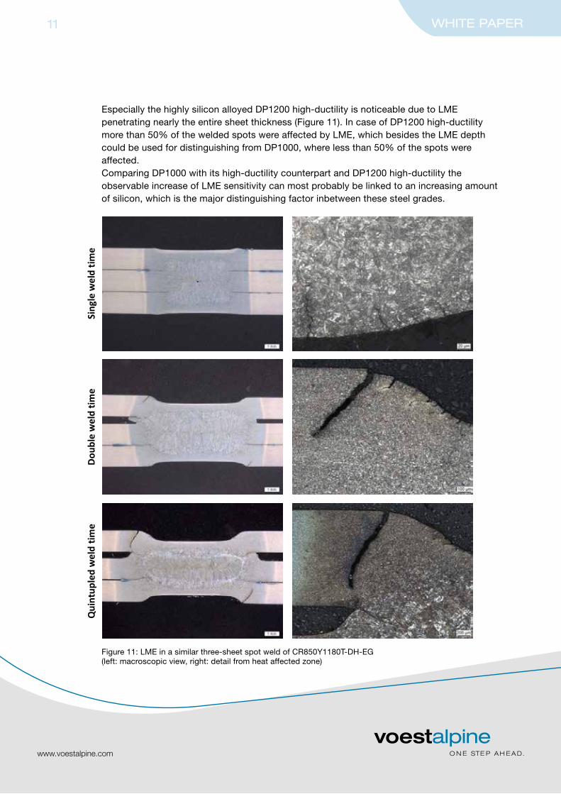
Especially the highly silicon alloyed DP1200 high-ductility is noticeable due to LMEpenetrating nearly the entire sheet thickness (Figure 11). In case of DP1200 high-ductilitymore than 50% of the welded spots were affected by LME, which besides the LME depthcould be used for distinguishing from DP1000, where less than 50% of the spots wereaffected.Comparing DP1000 with its high-ductility counterpart and DP1200 high-ductility theobservable increase of LME sensitivity can most probably be linked to an increasing amountof silicon, which is the major distinguishing factor inbetween these steel grades.
Figure 11: LME in a similar three-sheet spot weld of CR850Y1180T-DH-EG(left: macroscopic view, right: detail from heat affected zone)

10
Figure 12 shows that the LME sensitivity of CP1000 is quite low, as no severe LME can bedetected up to quintupled weld time. Generally the amount of alloying elements in complexphase steels is lower than in dual phase steels. Furthermore its microstructure mainlyconsisting of bainite accompanied by annealed martensite could be less sensitive incomparison to the microstructure of dual phase steels.
Sing
lew
eld
time
No LME foundin this macrosection.
Dou
ble
wel
dtim
eQ
uint
uple
dw
eld
time
Figure 12: LME in a similar three sheet spot weld of CR780Y980T-CP-GI(left: macroscopic view, right: detail from heat affected zone)
www.voestalpine.com
WHITE PAPER12
Figure 12 shows that the LME sensitivity of CP1000 is quite low, as no severe LME can bedetected up to quintupled weld time. Generally the amount of alloying elements in complex-phase steels is lower than in dual-phase steels. Furthermore its microstructure mainlyconsisting of bainite accompanied by annealed martensite could be less sensitive incomparison to the microstructure of dual-phase steels.
Figure 12: LME in a similar three-sheet spot weld of CR780Y980T-CP-GI(left: macroscopic view, right: detail from heat affected zone)

11
Nevertheless also with complex phase steels an increase in LME sensitivity can be observedcomparing CP1000 and CP1000 high ductility with LME showing up in the higher alloyedCP1000 high ductility (Figure 13). Again silicon has to be mentioned in this context,additionally the manganese content is slightly increased in the high ductility grade.
Sing
lew
eld
time
Dou
ble
wel
dtim
eQ
uint
uple
dw
eld
time
Figure 13: LME in a similar three sheet spot weld of CR780Y980T-CH-GI(left: macroscopic view, right: detail from heat affected zone)
www.voestalpine.com
WHITE PAPER13
Nevertheless also with complex-phase steels an increase in LME sensitivity can be observedcomparing CP1000 and CP1000 high-ductility with LME showing up in the higher alloyedCP1000 high-ductility (Figure 13). Again silicon has to be mentioned in this context,additionally the manganese content is slightly increased in the high-ductility grade.
Figure 13: LME in a similar three-sheet spot weld of CR780Y980T-CH-GI(left: macroscopic view, right: detail from heat affected zone)

www.voestalpine.com
WHITE PAPER14
03 Attempting to avoid LME during spot welding of zinc coated steels
For the investigation of countermeasures against LME the most sensitive steel gradeDP1200 high-ductility has been chosen. Prevention of LME has been aimed at by avoidinghigh strains and tensions in the desired area of the electrode intendation. Therefore electrodes with bigger electrode diameter and/or tip diameter have been used.
03.01. ExperimentalTable 2 shows the welded two and three-sheet combination. Both combinations are LMEcritical due to asymmetrical heat input with high heat concentration on the side of thesensitive DP1200 high-ductility. The same 1000 Hz-MFDC-pedestal type welder has beenused again applying single-pulse welding with constant current regulation.
Electrode has first been chosen F1-16-20-6 and then changed to F1-16-20-8 for bothcombinations. F1-20-22-8 has additionally been applied with the three-sheet combinationand A0-16-20 with the two-sheet combination. Squeeze time has been set to 500 ms generally.
Table 2: Welded combinations and welding parameters
Minimum and maximum welding current has then been determined according to SEP1220-2 in each case (Table 3).
Table 3: Minimum (Imin) and maximum (Imax) welding current
Sheet 1 Sheet 2 Sheet 3Eletrode(CuCrZr)
Electrodeforce[kN]
Weldtime[ms]
Holdtime[ms]
CR850Y1180T-DH-EG(1.2 mm)
CR22MnB5press hardened
(1.5 mm)
CR440Y780T-DP-GI(0.8 mm)
F1-16-20-6F1-16-20-8F1-20-22-8
4.3 500 400
CR850Y1180T-DH-EG(1.2 mm)
CR3-EG (0.8 mm)F1-16-20-6F1-16-20-8
A0-16-20-402.3 280 200
Sheet 1 Sheet 2 Sheet 3Eletrode(CuCrZr)
Imin
[kA]Imin
[kA]
CR850Y1180T-DH-EG(1.2 mm)
CR22MnB5press hardened
(1.5 mm)
CR440Y780T-DP-GI(0.8 mm)
F1-16-20-6F1-16-20-8F1-20-22-8
5.75.86.0
6.68.58.5
CR850Y1180T-DH-EG(1.2 mm)
CR3-EG (0.8 mm)F1-16-20-6F1-16-20-8
A0-16-20-40
6.16.25.8
7.89.07.6

Additional improvement can be achieved by the use of electrode type A0, where LME isclearly reduced compared to F-type electrodes. This shows that the basic idea of reducingstresses and strains in the observed region is practicable, nevertheless some uncritical LME remains (Figure 17).
www.voestalpine.com
WHITE PAPER15
Figure 16: LME in the CR850Y1180T-DH-EG-sheet of a dissimilar two-sheet weld(left: F1-16-20-6, welded at Imax = 7.8 kA; right: F1-16-20-8, welded at Imax = 9.0 kA)
14
Figure 16: LME in the CR850Y1180T-DH-EG-sheet of a dissimilar two sheet weld(left: F1-16-20-6, welded at Imax=7.8 kA; right: F1-16-20-8, welded at Imax=9.0 kA)
Additional improvement can be achieved by the use of electrode type A0, where LME isclearly reduced compared to F-type electrodes. This shows that the basic idea of reducingstresses and strains in the observed region is practicable, nevertheless some uncritical LMEremains (Figure 17).
Figure 17: LME in the CR850Y1180T-DH-EG-sheet of a dissimilar two sheet weld(A0-16-20-40, welded at Imax=7.6 kA)
5. Summary
It has been shown that a modified SEP1220-2-procedure can be used for distinguishing theLME sensitivity of zinc coated high strength steels. Therefore the maximum welding currentof a similar two sheet combination has been determined strictly according to SEP1220-2. Forthe determination of LME sensitivity this welding current has then been applied in a similarthree sheet combination of the same steel and heat input has been increased by extendingthe weld time. With this approach LME has been provoked in the circumferential area of thespot weld electrode. Up to a tensile strength of 800 MPa LME sensitivity of electrolyticallyand hot dip galvanized steels has turned out to be low in this test. LME has been observedstarting at a tensile strength level of 1000 MPa and above.
Figure 17: LME in the CR850Y1180T-DH-EG-sheet of a dissimilar two-sheet weld(A0-16-20-40, welded at Imax = 7.6 kA)

www.voestalpine.com
WHITE PAPER16
04 SummaryIt has been shown that a modified SEP1220-2-procedure can be used for distinguishing theLME sensitivity of zinc coated high strength steels. Therefore the maximum welding currentof a similar two-sheet combination has been determined strictly according to SEP1220-2. Forthe determination of LME sensitivity this welding current has then been applied in a similarthree-sheet combination of the same steel and heat input has been increased by extendingthe weld time. With this approach LME has been provoked in the circumferential area of thespot weld electrode. Up to a tensile strength of 800 MPa LME sensitivity of electrolyticallyand hot dip galvanized steels has turned out to be low in this test. LME has been observedstarting at a tensile strength level of 1000 MPa and above.
The increased LME sensitivity of advanced high strength steels with high ductility suggeststhat LME is not mainly a question of strength but more of chemical composition andmicrostructure. Complex-phase steels appeared less sensitive to LME in comparison to dual-phase steels because of their lower alloying content. High-ductility grades have beenobserved more sensitive in comparison to their respective classic counterparts due to theirhigher alloying content.
Countermeasures against LME have been applied by using spot welding electrodes withbigger electrode diameter and/or bigger tip diameter in LME-critical combinations. LMEcould be reduced for all combinations but not eliminated entirely.