a critical review of researches on anchorages with end...
TRANSCRIPT

2937 | International Journal of Current Engineering and Technology, Vol.4, No.4 (Aug 2014)
Review Article
International Journal of Current Engineering and Technology E-ISSN 2277 – 4106, P-ISSN 2347 - 5161
©2014 INPRESSCO®
, All Rights Reserved
Available at http://inpressco.com/category/ijcet
A Critical Review of Researches on Anchorages with End Hooks and Bends in
Reinforced Concrete Structures
Rizgar Amin AghaȦ*
ȦFaculty of Engineering, University of Sulaimani - Kurdistan Region of Iraq
Accepted 25 August 2014, Available online 28 Aug2014, Vol.4, No.4 (Aug 2014)
Abstract
This paper reviews the most experimental works on anchorages by hooked and bent bars in reinforced structure. Some of
these works resulted in forming expressions to design bond strength by codes of practice like ACI. None of these works
represent the real structure conditions as they were carried out on pull-out specimens except those unpublished tests by
Gulparvar which applies directly to anchorages at simple supported beams. There is Schiessl’s theoretical approach to
treat and calculate anchorage resistance based on the of the compatibility of deformations between straight lead lengths
and terminal bends and hooks.This review has been done as a part of a research study and used as a base to undertake a
substantial test program on end anchorage at simply supported beams at London South Bank University between 2003-
2005 by the author of this paper to obtain PhD in structural engineering. The present situation seems to be that there are
5 results by Gulparvar available from tests to failure of 90 bends at supports and none for
180 bends. There are
probably isolated results from tests in which unintended anchorage failures have occurred, but the total of information is
clearly very small.
Keywords: Bearing stress, 180o hooks or 90
o bends, tail length, concrete strength, concrete cover, transverse
reinforcement, transverse pressure
1. Introduction
1 If the end anchorage of a bar is assisted by a bend or hook,
the action of the bend produces a concentrated
compression on the concrete which produces transverse
tension. Failure is often by splitting which is generally
attributed solely to the bearing effect. A pull-out failure
with the bar slipping around the bend is also possible.In
addition to the factors mentioned previously in part one in
relation to bond others which should be considered in
relation to bent anchorages are:
The considerable movement of the bar corresponding
to the compression within the bend, which may make
it impossible for the resistance of the bend to be fully
mobilized while.
The bond in the lead length is still intact.
The uncertainty about the distributions of the bond
and bearing stresses around a bend.
The possibility of the splitting effects from bond and
bearing being combined and so reducing the
resistance to splitting.
2.Pull-out experimental works
2.1 Mylrea(Mylrea T.D.1928)
The first tests of end hooks that seem to be of any real
interest appear to have been those by Mylrea. His type of
*Correspoding author Rizgar Amin Agha (BSc, MSc, PhD) is working
as Senior Lecturer
test specimen is illustrated by Fig.(1). It is to some extent a
model of a beam end, but the reaction R on the left
produces no transverse pressure in the area of the lead
length and hook. The bars were plain round with a
diameter of 12.7 mm . The internal radius of bend varied
from zero, i.e. a bar bent flat against itself, up to 11 . In
ten specimens there was no other reinforcement. In twelve
the hook was surrounded by a helix with 5,7 or 10 turns of
6.3 mm wire. The concrete cylinder strength varied from
13.6 to 24.6 2/ mmN .
Fig.1Mylrea’s test arrangements
In all the tests the steel stresses exceeded the elastic limit.
Some were terminated at large movements and in some the
bars fractured where the wire used for slip movement was
Dial 1Dial 2
38.1
114.3
T
R
R
R
She
ath
12.7
38.1
67
118
38.1
38.1
571.
6
228.6228.6

Rizgar Amin Agha A Critical Review of Researches on Anchorages with End Hooks and Bends in Reinforced Concrete structures
2938 |International Journal of Current Engineering and Technology, Vol.4, No.4 (Aug 2014)
fixed, but the majority failed by splitting. Where the bends
had normal internal radii ( 5.2 ), the movements at both
the dial gauges shown in Fig.(1) were around the bend, i.e.
upward at gauge 2 and downward at gauge 1. However for
r , and in late stages for r , at gauge 2 the bar
moved downward and the end bearing of the bar bent the
whole anchorage.
In calculating nominal bearing stresses bnomb AF /, ,
Mylrea included the end face of the bar in the bearing area
for r and r , making rAb 24/2 . For larger
radii of bend rAb 2 .Thus, for a given value of F , his
nominal bearing stresses were much lower than those
calculated by current methods ( rFb / ).Mylrea’s
calculations assumed a high bar stiffness and flexural
strength, while present methods ignore the bending
stiffness and strength.The present approach is reasonable
for large radii of bend, but bar flexure does appear to play
a role for small radii- as r approaches zero, b does not
tend to infinity. In Mylrea’s tests the resistances of
anchorages with r and r were practically the same
as those for 5.2r
2.2 Muller(Muller.H.H.1968)
Muller made 500 tests of which 300 were on ribbed bars
with terminal hooks or bends. The bar sizes were 8,12 and
18 mm and the tests specimens were 200 mm cubes for the
two smaller bar sizes and 300 mm cubes for the 18 mm
bars.The bars had straight bonded lengths 2 before and
after the bends.
2.3 Hribar and Vasko(Hribar J.A et al. 1975)
In the tests by Hribar and Vasko hollow-ram jacks reacting
against the top surfaces of concrete blocks were used to
apply tension to anchorages embedded in the blocks.The
bars were debonded from the surface down to the levels of
the beginnings of the anchorages, which were at the starts
of the curves of 90 bends and 180 hooks.The bars had
stress-strain curves which were linear up to about 400 2/ mmN and had a well-defined yield at about 422 2/ mmN
.The ultimate stresses were about 650,680 and 730 2/ mmN for bar sizes of 12.7, 22.2 and 34.9
2/ mmN .
Their deformations complied with the provisions of
ASTM A305-56T which would appear to satisfy the
requirements of EC2.
The tests were continued until failure which was
generally by the fracture of the bars.The corresponding bar
stresses are not given in most cases- the ultimate stresses
quoted above are average values from the tests for which
ultimate stresses are given. Stresses corresponding to
givendisplacements and displacements corresponding to
given stresses are detailed in (Hribar J.A et al. 1975). The
displacements or slips given were obtained by subtracting
the elastic elongation of the bar between the measuring
point at the start of the anchorage from the total
displacement between the measuring point and the
concrete surface which would seem to involve significant
errors once the bar stresses exceeded the elastic limit.
The two main series of tests (series and ) were made
on bars cast in two large concrete blocks approximately
1.5 m deep and 4.6 m square(series ) or 3.04x3.66 m (series
). In these tests the depths to the starts of the anchorages
were generally 254, 457 and 616 mm for 12.7,22.2 and 34.9
mm bars. These depths were such that the calculated
pressure in the concrete was about 0.5 2/ mmN . In series
some tests were made in a large plain concrete block but
others were in small blocks (of unknown dimensions) with
heavy, but undefined reinforcement. Depths to the starts of
the bonded lengths varied but are not defined. Because of
uncertainties here, these tests are generally not considered
in the following.
The main conclusions drawn by Hribar and Vasko are
1. A well-defined relationship exists between average
bond stress and bonded length for each bar size and is
relatively insensitive to the type of anchorage ( straight or
bent ). Although this is not stated in (Hribar J.A et al.
1975) this conclusion relates to average stress at a given
slip( principally 0.25 mm ). In the few cases where pull-out
failures occurred, the ultimate bond stresses were
practically independent of bar size. The relationships
drawn in (Hribar J.A et al. 1975)show the bond stress
increasing for increasing bar size. This is misleading, as a
more rational basis for comparison would be the bond
stresses for different bar sizes in tests with equal /bl (not
equalbl ). From the paper's Fig.2, which shows bond
stresses at 0.25 mm slip,for bar sizes of 12.7, 22.2 and
34.9 mm , the bond stresses at 10/ bl are 9.4,9.0 and 8.8 2/ mmN and those at 20/ bl are 6.2,4.7 and 5.5 2/ mmN
.Thus for similar values of /bl the bond stress for a given
slip decreases relatively slightly, with increasing bar size.
2. Hook geometry and embedment length were the prime
factors affecting the pull-out characteristic of a bar.Prior to
yielding the efficiency of an anchor decreased with
increase in hook angle, but beyond yield of the steel a 180
hook performed better than a 90 hook. An increase in
radius of hook increased the efficiency of an anchor more
than an extension beyond the hook.
3. Point (1) above suggests that anchors, curved or
straight, can be designed on the basis of bond alone.
4. The results are based on tests in which splitting was
prevented by either mass concrete or (in series only)
auxiliary reinforcement and would be applicable to such
situations. The value of an anchor should be based on the
ultimate concrete strength and the restraint against
splitting. A distinct linear relationship exists between
stress and loaded end displacement at low bar stresses
(100 2/ mmN for 34.9 mm bars to 240 2/ mmN for 12.7 mm
bars). Deviation from a linear relationship indicated
incipient crushing of the concrete or incipient bond failure,
which could significantly alter the effectiveness of anchors
at high working stresses under fatigue conditions.
Points (3) and (4) seem confused. In view of (4) it is
clear that anchorages should not be designed on the risk of
their causing splitting. A rather more rational

Rizgar Amin Agha A Critical Review of Researches on Anchorages with End Hooks and Bends in Reinforced Concrete structures
2939 |International Journal of Current Engineering and Technology, Vol.4, No.4 (Aug 2014)
interpretation of the test results would seem to be as
follows:
1. For the serviceability limit state, the steel stress
corresponding to 0.25mm slip at the loaded end of an
anchorage can be calculated assuming an average bond
stress along it of
c
b
bf
lkf
3/2
25.0,
in SI units. (1)
An average value of 3/210k
This relationship is compared with the test results from
series II and III in Fig.(2). It should be noted that it is
derived from tests with effectively infinite cover. It should
however apply more generally providing the cover does
not split at the load in question, which is probable at
service loads,if uls requirements are met.Also it applies to
first loading and the slip could be expected to increase
with repeated loading.
Fig. 2 Average bond stresses at 0.25mm loaded-end
sliptest series 1,2 and 3 by Hribar and Vasko
2. The test data are insufficient for any definitive
conclusions to be drawn for uls design. No splitting
failures occurred in spite of the bearing stresses in bends
being up to cf7 , cf6 and cf5 for the standard bend radii of5.2 ( mm7.12 ), mm2.220.3 and mm9.340.4 . All of
these are in excess of maximum characteristic resistances
obtained from EC2 and BS8110 by setting /a in their
equations.
There were a few pull-out failures (not accompanied
by any visible cracking of the blocks and the results for
these are shown in Fig.(3), where the average bond stress
at failure is plotted against /bl .The results include the
bond failures of the series tests of bars cast in a large
block. For 10/ bl , there appears to be a fairly clear
relationship between cbu ff / and /bl , valid for both
straight and bent anchorages. This could be expressed in a
form similar to that used above for 25.0,bf , i.e.
cb
bu fl
f
3/210
25.2
(2)
Fig. 3 Ultimate bond stresses, tests by Hribar and Vasko
In relation to both of the above conclusions, the effect of
concrete strength on bond resistance has been assumed to
be one of proportionality between bf and cf .The test
results do not contradict this, but the variation of cf was
very limited - cf =29.0 , 32.7 and 25.52/ mmN respectively
for series I, II and III. The possibility of direct comparison
between Hribar and Vasko and Muller is very limited, but
some observations can be made.
1. Table (1) gives Hribar and Vasko’s results for the steel
stresses developed at loaded end slips of 0.2 mm in tests
of 180o hooks with varying tail lengths, fc was 32.75N/m
2.
While Muller’s conclusion that tail lengths have no
0
0.5
1
1.5
2
0 10 20 30 40 50 60
c
b
b fl
f
3/2
25.0,
10
/bl
c
b
f
f 25.0,
0
0.5
1
1.5
2
0 10 20 30 40 50
c
b
b fl
f
3/2
25.0,
10
c
b
f
f 25.0,
/bl
0
0.5
1
1.5
2
0 10 20 30 40 50
/bl
c
b
f
f 25.0,
c
b
b fl
f
3/2
25.0,
10
0
0.5
1
1.5
2
2.5
3
3.5
4
0 5 10 15 20 25
c
bu
f
f
/bl
c
b
bu fl
f
3/2
1025.2
bends
bends
anchorage
straight
180
90
KEY
Straight anchorages
900 bends with standard radii
and t=4
t=8
t=12
other 900 bends
1800 bends with standard radii
and t=4 or
other 1800 bends

Rizgar Amin Agha A Critical Review of Researches on Anchorages with End Hooks and Bends in Reinforced Concrete structures
2940 |International Journal of Current Engineering and Technology, Vol.4, No.4 (Aug 2014)
Table 1Effect of tail length on bar stresses at slip of mm25.0 ( Hribar and Vasko)
Specimens 2-14 2-15 2-16 2-20 2-21 2-22 2-26 2-27 2-28
)(mm 12.7 12.7 12.7 22.2 22.2 22.2 34.9 34.9 34.9
/r 2.5 2.5 2.5 3.0 3.0 3.0 4.0 4.0 4.0
/tl 0 2 5 0 2 4 0 2 4
2
25.0, / mmNf s 219 212 218 157 196 218 103 214 260
Table 2Effect of radius of bend on bar stresses at slip of mm25.0 for bars with 0tl ( Hribar and Vasko)
Specimens 2-14 2-39 2-40 2-20 2-34 2-35 2-36 2-26 2-43
)(mm 12.7 12.7 12.7 22.2 22.2 22.2 34.9 34.9 34.9
/r 0 0 0 0 0 0 0 0 0
/tl 2.5 3.5 4.5 3.0 3.5 4.0 4.5 4.0 6.0
2
25.0, / mmNf s 219 276 307 157 202 243 303 103 312
influence on bar stresses at slips up to 0.2 mm is supported
by the results for the smallest bar size, it is clearly
contradicted by those for the larger bar sizes both of which
had were greater than the 18mm maximum size tested by
Muller.
2. Muller indicates the effect of the radius of bend by a
diagram valid for slips up to mm2.0 which shows that in
relation to the bar stress for 5.2r , there is a 20%
reduction when 25.1r and a 25% increase when
0.5r .Table (2) gives Hribar and Vasko’s results for
180 hooks with varying radii of bend ( all for cf 32.752/ mmN ). It is true that the tests by Hribar and Vasko were
made on bars with 0/ tl, while in Muller's 5tl , but
according to Muller /tl has no influence on 2.0,sf .The
results above show the bars stresses to have increased by
40% for an 80% increase of /r when mm7.12 , by 93%
for a 100% increase of /r when mm2.22 and by
203% for a 50% of /r when mm9.34 . All of these
increments are much greater than Muller’s 25% for a
100% increase of /r .
2.4 Minor and Jirsa(Minor J. et al. 1975)
Minor made 38 pairs of pull-out tests to examine the
influences of various parameters on the capacities of
anchorages by bends.The bars were embedded in plain
concrete blocks as shown in Fig.(4), with their lead lengths
“c” debonded. The primary variables were the total
bonded length ( 8.4bl to 7.9 ) , the angle of bend ( 0 to180 ), the internal radius of bend ( 6.1r to 7.5 ) and the
bar diameter (16,22 and 28 mm ).The tail length varied as a
function of bl and r . The concrete strength cf was
generally in the range from 25 to 40 2/ mmN . Measurements
of slip were made at both ends of the bond lengths and at
the some intermediate points.
The test arrangement seems far from ideal as the node
formed by the vectors of the applied forces lies outside the
bar. According to (Minor J. et al. 1975).
,,, lr Variable
Bar size
(mm)
Dimensions(mm)
a b c
15.9 305 203 152
22.3 406 203 203
28.6 406 305 190
Fig. 4Minor and Jirsas' test arrangements
In nearly all the tests the bond lengths were short enough
to produce bond failure rather than bar or concrete
fracture”, but 19 tests were terminated at high stress or
large slip and for these the maximum loads are unknown.
A further 32 failed by fracture of the concrete.This failure
mode is not described but can reasonably be assumed to be
splitting resulting from bond and bearing stresses.The
remaining 25 tests ended in pull-out failures. In many of
the tests the maximum stresses in the bars exceeded their
nominal yield stress of 414 2/ mmN .The maximum stress
reported is 531 2/ mmN .Minor and Jirsa concluded that:
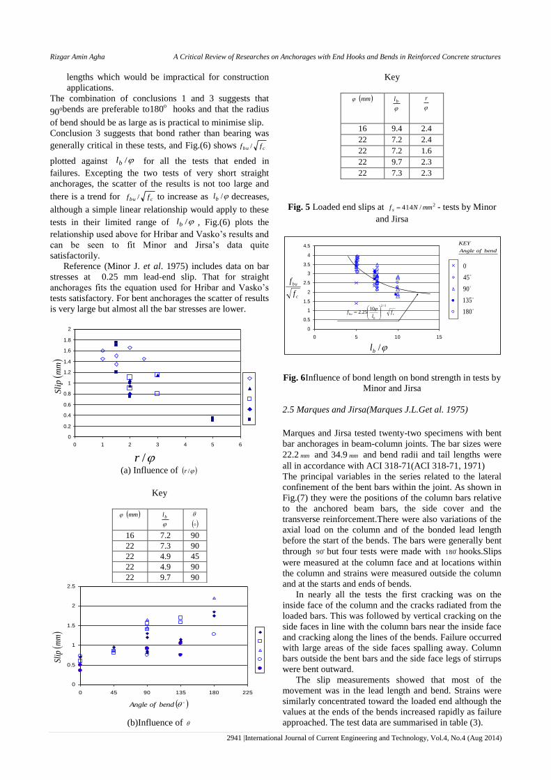
1. For equal ratios /bl , the larger the angle of the bend
, the greater is the slip at a given bar stress and the
smaller the ratio /r , the greater is the slip at a
given bar stress. Fig.(5) shows that this is broadly true
for a bar stress of 414 2/ mmN .
2. In an anchorage consisting of both bent and straight
(tail) sections most of the slip is developed in the
curved section.
3. There is little difference in strength between straight
and bent bar anchorages except for a very short bond
38 a
C =T
R
R
c
r
T
a
a
b
Rizgar Amin Agha A Critical Review of Researches on Anchorages with End Hooks and Bends in Reinforced Concrete structures
2941 |International Journal of Current Engineering and Technology, Vol.4, No.4 (Aug 2014)
lengths which would be impractical for construction
applications.
The combination of conclusions 1 and 3 suggests that
90obends are preferable to180
o hooks and that the radius
of bend should be as large as is practical to minimise slip.
Conclusion 3 suggests that bond rather than bearing was
generally critical in these tests, and Fig.(6) shows cbu ff /
plotted against /bl for all the tests that ended in
failures. Excepting the two tests of very short straight
anchorages, the scatter of the results is not too large and
there is a trend for cbu ff / to increase as /bl decreases,
although a simple linear relationship would apply to these
tests in their limited range of /bl , Fig.(6) plots the
relationship used above for Hribar and Vasko’s results and
can be seen to fit Minor and Jirsa’s data quite
satisfactorily.
Reference (Minor J. et al. 1975) includes data on bar
stresses at 0.25 mm lead-end slip. That for straight
anchorages fits the equation used for Hribar and Vasko’s
tests satisfactory. For bent anchorages the scatter of results
is very large but almost all the bar stresses are lower.
(a) Influence of /r
Key
mm
bl
16 7.2 90
22 7.3 90
22 4.9 45
22 4.9 90
22 9.7 90
(b)Influence of
Key
mm
bl
r
16 9.4 2.4
22 7.2 2.4
22 7.2 1.6
22 9.7 2.3
22 7.3 2.3
Fig. 5 Loaded end slips at 2/414 mmNf s - tests by Minor
and Jirsa
Fig. 6Influence of bond length on bond strength in tests by
Minor and Jirsa
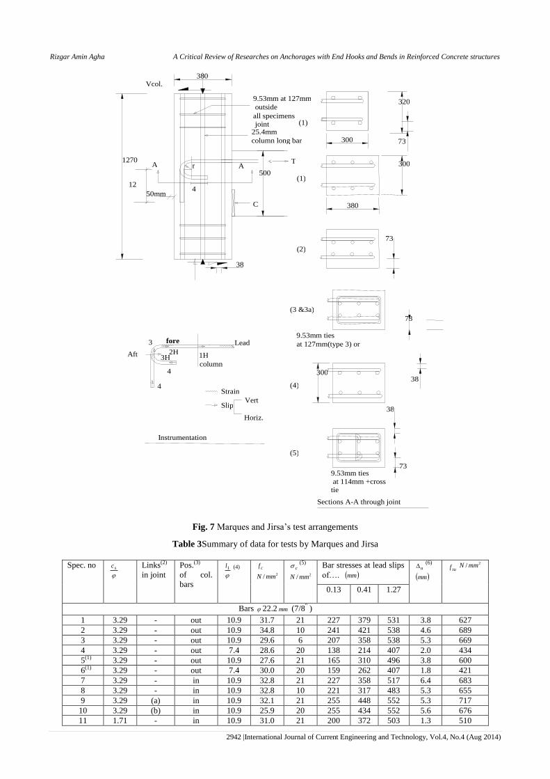
2.5 Marques and Jirsa(Marques J.L.Get al. 1975)
Marques and Jirsa tested twenty-two specimens with bent
bar anchorages in beam-column joints. The bar sizes were
22.2 mm and 34.9 mm and bend radii and tail lengths were
all in accordance with ACI 318-71(ACI 318-71, 1971)
The principal variables in the series related to the lateral
confinement of the bent bars within the joint. As shown in
Fig.(7) they were the positions of the column bars relative
to the anchored beam bars, the side cover and the
transverse reinforcement.There were also variations of the
axial load on the column and of the bonded lead length
before the start of the bends. The bars were generally bent
through 90 but four tests were made with 180 hooks.Slips
were measured at the column face and at locations within
the column and strains were measured outside the column
and at the starts and ends of bends.
In nearly all the tests the first cracking was on the
inside face of the column and the cracks radiated from the
loaded bars. This was followed by vertical cracking on the
side faces in line with the column bars near the inside face
and cracking along the lines of the bends. Failure occurred
with large areas of the side faces spalling away. Column
bars outside the bent bars and the side face legs of stirrups
were bent outward.
The slip measurements showed that most of the
movement was in the lead length and bend. Strains were
similarly concentrated toward the loaded end although the
values at the ends of the bends increased rapidly as failure
approached. The test data are summarised in table (3).
0
0.2
0.4
0.6
0.8
1
1.2
1.4
1.6
1.8
2
0 1 2 3 4 5 6
/r
mm
Sli
p
0
0.5
1
1.5
2
2.5
0 45 90 135 180 225
mm
Slip
bendofAngle
0
0.5
1
1.5
2
2.5
3
3.5
4
4.5
0 5 10 15
c
bu
f
f
/bl
c
b
bu fl
f
3/2
1025.2
180
135
90
45
0
bendofAngle
KEY
Rizgar Amin Agha A Critical Review of Researches on Anchorages with End Hooks and Bends in Reinforced Concrete structures
2942 |International Journal of Current Engineering and Technology, Vol.4, No.4 (Aug 2014)
Fig. 7 Marques and Jirsa’s test arrangements
Table 3Summary of data for tests by Marques and Jirsa
Spec. no
sc
Links(2)
in joint
Pos.(3)
of col.
bars
1l (4) cf 2/ mmN
c(5)
2/ mmN
Bar stresses at lead slips
of…. mm u
(6)
mm suf
2/ mmN
0.13 0.41 1.27
Bars 22.2 mm (7/8" )
1 3.29 - out 10.9 31.7 21 227 379 531 3.8 627
2 3.29 - out 10.9 34.8 10 241 421 538 4.6 689
3 3.29 - out 10.9 29.6 6 207 358 538 5.3 669
4 3.29 - out 7.4 28.6 20 138 214 407 2.0 434
5(1) 3.29 - out 10.9 27.6 21 165 310 496 3.8 600
6(1) 3.29 - out 7.4 30.0 20 159 262 407 1.8 421
7 3.29 - in 10.9 32.8 21 227 358 517 6.4 683
8 3.29 - in 10.9 32.8 10 221 317 483 5.3 655
9 3.29 (a) in 10.9 32.1 21 255 448 552 5.3 717
10 3.29 (b) in 10.9 25.9 20 255 434 552 5.6 676
11 1.71 - in 10.9 31.0 21 200 372 503 1.3 510
2H
50mm
(3 &3a)
(4)
(5)
(2)
(1)
(1)
A A
Sections A-A through joint
73
38
9.53mm ties
at 114mm +cross tie
9.53mm ties
at 127mm(type 3) or
300
320
380
300
73
300
Vert
Horiz.
Slip
Strain
4
4
fore Lead
1H
column 3H
3
Aft
38
Vcol.
500
1270 r
9.53mm at 127mm
outside
joint all specimens
25.4mm
column long bar
4
T
C
12
380
Instrumentation
38
73
73

Rizgar Amin Agha A Critical Review of Researches on Anchorages with End Hooks and Bends in Reinforced Concrete structures
2943 |International Journal of Current Engineering and Technology, Vol.4, No.4 (Aug 2014)
Bars 34.9 mm (
8
31
)
12 2.09 - out 4.4 33.8 21 131 227 331 1.5 338
13 2.09 - out 4.4 32.8 6 131 200 331 1.5 358
14 2.09 - out 2.2 31.7 21 124 207 - 1.0 290
15(1) 2.09 - out 4.4 30.3 21 90 172 296 1.3 303
16(1) 2.09 - out 4.4 30.0 5 179 255 - 1.3 345
17 2.09 - in 4.4 34.5 21 152 241 331 1.5 331
18 2.09 - in 4.4 31.0 5 124 193 345 1.5 365
19 2.09 (a) in 4.4 33.4 6 110 193 365 2.3 427
20 2.09 (b) in 4.4 34.5 7 165 290 455 1.5 476
21 1.09 - in 4.4 28.3 5 179 269 - 0.8 303
22 2.09 (c) in 4.4 34.5 5 159 269 434 2.0 455
Note:
1.Specimens with 180 hooks, all others had 90 bends.
2.(a)- 5.9 @127 , (b)- 5.9 @63 , (c)- 5.9 +cross tie @63
3.Out-column bars outside beam bars , In- column bars inside beam bars.
4. 1l =lead length.
5.Column load/column area.
6.Lead slip at failure.
For mm2.22 bars /r =3 ; for mm9.34 bars /r =4
For 90 bends tail length= 12 ; for 180 bends tail length= 4
yf for the anchored bars =450 to 475 2/ mmN
The conclusions reached by Marques and Jirsa were
1. In contrast to the results from Minor and Jirsa, there
was little difference in behaviour between the
specimens with 90o and 180
o and bends.
2. The specimens with longer lead lengths developed
less slip and higher bar stresses than those with
shorter leads.
3. The location of the main column bars had little effect.
4. Column links within the joints improved performance,
particularly for the larger beam bars.
5. Axial loading of the column had little effect.
The relevant provisions of ACI 318-71 were reviewed in
the light of the test results. The bond in the lead length was
calculated via the basic expression for development
lengths for bottom-cast bars. The bar stresses developed
by bends plus tails were calculated as cf where
8.14 for 2.22 and 9.29 for 9.34 ( in SI
units).The ratios of experimental to computed bar stresses
varied from 1.19 to 1.86 with a mean of 1.47 and a
coefficient of variation of 13.3%.
An alternative design procedure was proposed.
According to this the bar stress developed by a standard
hook or bend is
ch ff 85/158 ( N, mm ) (3)
Where: =1.4 if mm35 and the bonded lead length
mml 1021 and the side cover is not less than 63mm and
the cover on the tail extension is not less than 51 mm.
=1.8 if the conditions above are complied with and in
addition the joint is confined by closed ties at a spacing
3 . =1.0 in all other cases.
No increase in bar stress is allowed for tail extensions
or bend radii greater than those of standard hooks and
bends. If the bonded lead length mm102 , the increase
of bar stress can be calculated assuming a bond stress
equal to /8 cf . In overall terms this modification of
ACI 318 has little effect on the correlation of experimental
and computed strengths. The mean ratio is reduced from
1.47 to 1.43 while the coefficient of variation is
unchanged.
The Marques and Jirsa alternative is clearly the basis
of the current ACI 318.This does, to some extent, explain
the oddly arbitrary use of fixed covers etc. rather than
dimensionless quantities such as /sc . Further analysis
of these results would be very difficult. Inspite of strain
measurements having been made at the beginnings and
ends of the bends, the results are given for only two
specimens, one with 22.2 mm bars and one with 34.9 mm
bars. In both cases, the tail bond stresses were initially
much lower than those in the curves, but were rising
rapidly close to failure. For the smaller bars, the lead
length bond stresses were initially highest , but reduced in
the latter stages, while for the larger bars they were
initially small and were practically zero above half the
ultimate load. With the forces at the starts of the bends
unknown it is unrealistic to make comparisons with
calculated bearing resistances. If the bond stress is taken
as being uniform along the whole length bl the bearing
stresses for the specimens without transverse
reinforcement are on average 27% above BS8110
predictions for the smaller bars but for the large bars they
are 24% below BS8110 values. The variation may be a
matter of behaviour in relation to bond/anchorage but
there are also issues related to the other actions in beam-
column joints. As can be seen from table (3) the provision
of stirrups within the joint region did increase the forces
anchored but for the smaller main bars the stirrups at
St=5.7 gave a higher result than that for stirrups at 85.2
. For the larger bars, with 8.1ts the results were higher
than for stirrups at 6.3

Rizgar Amin Agha A Critical Review of Researches on Anchorages with End Hooks and Bends in Reinforced Concrete structures
2944 |International Journal of Current Engineering and Technology, Vol.4, No.4 (Aug 2014)
Fig. 8 Soroushian et al’s test arrangements
Table 4 Summary of results of tests by Soroushian et al.
Spec.
no.
cf
2mm
N
mm
Stirrups
t
st
s
A
suF
kN
suf 2/ mmN
c
bu
f
f
bu 2/ mmN
c
bu
f
1 26.1 25.4 [email protected] 0.037 294 580 1.62 152 5.82
2 26.1 25.4 [email protected] 0.037 268 528 1.48 138 5.31
3 26.1 25.4 [email protected] 0.028 208 410 1.15 107 4.12
4 26.1 25.4 [email protected] 0.065 313 617 1.72 162 6.20
5 41.7 25.4 [email protected] 0.037 292 576 1.27 151 3.62
6 26.1 19.1 [email protected] 0.049 193 674 1.88 176 6.75
7 26.1 31.8 [email protected] 0.029 350 441 1.13 87 3.31
Note: specified yield stress of reinforcement= 480 2/ mmN , suF = force in one bar.
2.6 Soroushian , Obaseki , Nagi and Rojas(Soroushian P.
et al. 1988)
Soroushianet al. tested anchorages of 090 bends. The test
arrangements shown in Fig.(8) to some extent simulated
conditions at beam-column joints, but without vertical
load and with unrealistic reactions on the columns. In all
the tests the bends had 12 long tails and ACI standard
internal radii of 3 for mm19 and mm25 bars and 4 for mm32
bars. The variables were the confining reinforcement, the
concrete strength and the bar size. Behaviour was similar
in all tests. Initially at about half the ultimate load
horizontal cracking occurred on the side faces in the plane
of the two bars, and extended along the bends with
increasing load. Vertical cracks in the planes of the bends
appeared close to failure and the side cover split away.
The test results are summarised in table (4) for which
ultimate loads have been scaled from graphs in
(Soroushian P. et al. 1988). Soroushian et al. conclude
that
1. Pull-out resistance increases with increasing bar
diameter , but the increase is lower than the
corresponding rise in the bar yield force. (The
ultimate bar force was approximately proportional to
in the three relevant tests).
2. Confinement of concrete surrounding the hook is an
important factor influencing the hook performance.
3. Concrete compression strength did not influence the
hook pull-out behaviour in the limited tests.
They also modified an empirical equation by Eligehausen
for the relationship between the bar stress and the loaded-
end slip to fit their test results. For the rising branch of
loading, the expression given amounts to
2.0,, 54.2/ uss FF , with in mm and 25.005.0271, usF
in KN and mm ( Note the US to SI conversion in reference
(55) is incorrect).
Conclusions 1 to 3 are a fair reflection of the test
results. The third of them is the most surprising and is
supported by only one variation of the concrete strength.
The only obvious explanation for it would be that at the
ultimate limit the restraint against splitting provided by the
transverse reinforcement predominates over that from the
concrete.
The second conclusion is supported by the results for
four tests, all with the same bar size, bend radius, cover
and concrete strength. The circle points in Fig.(9) show
cbu f/ and tst sA / for these tests and do suggest a
relationship passing through the origin. The two other
points show that any general relationship would need to
take account of the effects of bar size, and other factors.
Account may also need to be taken of the presence of the
large volume of concrete in front of the anchorages and
not subjected to any direct effects from bond stresses. In
regard to the first conclusion, it can be noted that, in the
relevant tests, the forces developed were approximately
proportional to the bar size, but the tests did involve
variations of the ratios /sc and /r as well as the ratio of
the area of transverse reinforcement to that of the anchored
bars.
In relation to serviceability the proposal by Soroushian
applied to the typical specimens with 25.4 mm bars gives
a steel stress of 233N/m2 at a slip of0.25 mm and this
agrees well with 247 N/m2 given by the equation derived
above from the tests by Hribar and Vasko.
12
51
297
Column bars
425.4mm
355
51
stirrups 12.7mm
305
Debonded
305
596

Rizgar Amin Agha A Critical Review of Researches on Anchorages with End Hooks and Bends in Reinforced Concrete structures
2945 |International Journal of Current Engineering and Technology, Vol.4, No.4 (Aug 2014)
Fig. 9 Influence of transverse reinforcement on ultimate strength -tests by Soroushian et al.
Fig.10 Detailing of beams by Gulparvar
Table 5 Ultimate bond stresses at anchorages (N/m2)for Gulparvar's beams G4 and G6
Beam No Average Lead length Bend Tail
G4 8.00 8.10 12.16 2.03
G6 8.84 - 92.7 6.50
0
1
2
3
4
5
6
7
0 0.4 0.8 1.2 1.6
c
bu
f
mmsA tst /
4/8.31
3/4.25
3/1.13
r
r
r
Beam 1
40
0
200 200
32 25
32
10
01
25
10050
400175
100
125
10
01
25
400175
25
75
25
100
25
10
01
25
400175
175 400
50
10
0
1005050
75
12
5
400175
2T10
2T25
Stirrups
R6 @200c/c
175 400 400 500
A
support plates
150 mm long
Beam 5
Beam 2 Beam 3Beam 4
Beam 6

Rizgar Amin Agha A Critical Review of Researches on Anchorages with End Hooks and Bends in Reinforced Concrete structures
2946 |International Journal of Current Engineering and Technology, Vol.4, No.4 (Aug 2014)
Table 6 Results of tests by Gulparvar
Beam
No. bl
mm 1l
mm ec (4)
mm
cuf
2mm
N
P
2mm
N
buF
kN
1RKF
kN 2RKF
kN RK
bo
F
F
G1(1) 362.5 100 50 44.5 14.58 248 222 195 1.27
G2 376.7 75 50 53.4 15.00 252 233 264 1.08
G3(2) 376.7 75 50 51.0 14.83 249 247 241 1.03
G4(3) 401.7 100 25 53.2 15.00 >252 269 280 >0.94
G5 301.7 75 50 53.1 13.33 224 202 263 1.11
G6 301.7 0 125 51.0 12.50 209 198 204 1.06
Note: (1) mmr 75 in beam G1, mm100 in all others
(2) mmcs 25 in beam G3 , mm32 in all others
(3) beam G4 failed in shear in the other shear span
(4) ec = end cover
(5) in columns 8 and 9 underlinings indicate the critical calculated strength
3. Simply supported beam experimental work by
Gulparvar(Gulparvar D., 1997)
Gulparvar tested six simply supported beams to investigate
the anchorage capacities of 090 bends at supports. Details
of the beams are shown in Fig.(10). The variables were the
tail length, the radius of bend, the side cover, the end face
cover and the straight lead length over the support. In all
but one of the tests failure occurred at the support with the
bent anchorages. In these cases there was generally
cracking on the side faces along the lines of the bars
followed by vertical cracking (splitting) visible on the end
face in line with one or both of the bars. In beam G1 there
was a horizontal crack on the end face at the level of the
tops of the bars. In beam G5, where the tail lengths were
short, the failure seemed to be purely by the bars pulling
around the bends as there was no cracking on the end of
the beam. In beam G6, where the bends started at the inner
face of the support, the concrete within the bends spalled
out sideways. Beam G4 failed by shear in the shear span
with straight anchorages. The bar stresses at midspan were
at or close to yield ( 2/520480 mmNf y ) but those at the
supports were lower due to the action of the single stirrup (2/260 mmNf y ) in the shear span.
In beams G4 and G6 there were strain gauges at
opposite ends of diameters at the beginnings an ends of the
bends, and there was an extra pair at midspan in beam G6.
Bond stresses calculated from these strains are given in the
table (5).
For the normal anchorage in beam G4 with the bend
starting just beyond the centre of the support, the bond in
the tail remained low, although it should be noted that
there was no anchorage failure in this beam and the tail
length might have become more active in an anchorage
failure. In beam G6, where the bend began at the inner
face of the support and the anchorage length was reduced
the tail bond stress was much closer to the average.
Gulparvar proposed that the characteristic anchorage
capacity of a bar could be calculated as the lesser of the
values corresponding to bond and bearing failures.
bbpRKb lfF (4)
rlfF bbpRK 1 (5)
Where bpf is the BS8110(BS8110,2005) bond stress
( cub ff 7.0 ) modified by the MC90/EC2 (EuroCode
2,2004)coefficient allowing for the effect of transverse
pressure, bbbp fpff 67.104.01/ with P in Nm2 (note:
the ratio bbp ff /max, is greater than in EC2, but for the
beams in question max,bpf is practically as in EC2 due to
the Eurocode’s higher value for bf ). The upper limit
governs for all of Gulparvar’s beams, P is the transverse
pressure at the support, bl is the bonded length
( lead+bend+tail) over the support, 1l is the lead length
over the support and b is the limit stress for bearing in the
bend as given by BS8110.
Table (6) summarises the results of a comparison
between the actual anchorage resistances and values
calculated as above.
The agreement between the calculated and
experimental resistances is good, but the range of tests is
very limited.
The application of the influence of p to the whole
anchorage length including the vertical tail section seems
rather dubious.
4. Theoretical approach by Schiessl(Schiessl P.,1982)
Schiesslstudied anchorage resistance as a combination of
components from straight bar lengths and terminal bends
or hooks(or welded transverse bars). Bond – slip
relationships for straight bars were derived from the
results of pull-out tests with 5 bond lengths and
relationships between loaded-end bar stresses sof and
slips were found from tests of bends and hooks with 2
bonded lead lengths as shown in Fig.(11), ( see Muller in
2.6.2).
bf = ccu baf - for straight lengths (6)
e
cuso dff - for bent anchorages (7)

Rizgar Amin Agha A Critical Review of Researches on Anchorages with End Hooks and Bends in Reinforced Concrete structures
2947 |International Journal of Current Engineering and Technology, Vol.4, No.4 (Aug 2014)
where bf = bond stress sof = steel stress, 2 before start
of a bend.
=slip in general for straight bars or loaded-end slip for
bent anchorages.
The values of the coefficients a to e depend upon the bar
size and the bars’s position during concreting.
c
s
s
c
s
s
E
E
f
f
E
f
dx
d1 (8)
bs f
dx
df
4 (9)
Where sf = bar stress at section x and fc= concrete stress at
section x. bf = bond stress at section x.
Fig. 11 Bond lengths for bent and straight parts of
anchorages in Schiessl’s approach
If conditions at one section e.g. at the loaded end of a
hook+ 2 , are specified, the development of stress along
the straight length of the bar can be found from equations
(6, 8 and 9) and Schiessl used a finite difference approach
for this. The calculations start with defining a straight
anchorage length from 2 in front of bend then:
1- sof can be calculated for any assumed using
equation (8)
2- Calculating bf for the value of by eqn.(6) and
assuming it applies along a defined length,then at the end
of the length the developed sf is sum of the increment
calculated from eqn. (9) and 0,sf at the start of the length.
3- The developed elongation can be calculated from the
average stress in the length, and at the end of the length
is the sum of this and the slip 2 from the bend.4- The
process can be repeated for subsequent lengths using end
values of sf and for one length as the start values for
the next length till the developed steel stress reach the
required working value of 24N/m2.
Schiessl's criterion for determining the development
length for a bar with an end hook was that the slip at the
section of maximum bar stress should not be significantly
greater than that for a straight development length.
The maximum bar stress considered was related to
working load design and was 2402/mmN . With this level of
maximum stress the slip at the start of the bend is
relatively small and the contribution of the hook is limited.
Fig.(12), which is reproduced from (Schiessl
P.,1982)shows the reduction of anchorage length which is
obtained as a function of the increase of slip at the
beginning of the anchorage.The 30% reduction used in
DN1045 and the CEB-FIP model code of 1978( and
subsequently in EC2) corresponds to a 5 to 10% increase
of slip.
Fig. 12 Results of all calculations ,288 mm
2/5525 mmNfcu for ribbed bars in upper and lower
positions from Schiessl
This work is of interest as it appears to be the background
of EC2’s treatment of hooks and bends using the
coefficient 1 . It does however have severe limitations. It
is a working stress method and not one for the ultimate
limit state. Its criterion for determining the deformation
limit, which governs the contribution of a hook, is not a
realistic performance criterion as it does not define
capacity or even a crack width. As applied by Schiessl it
has the further problem that the concrete stress cf , and
thence the shortening of the concrete, is determined
assuming that a prism of concrete develops a stress equal
to scc AAf / ,where cA is the area of the prism and sA is the
area of the bar. This is not realistic for the flexural tension
zone of a beam, in which the concrete cracks. Using the
expression ecuso dff to calculate the bar stress at a slip
of 0.255mm,with d=16.5 for an upward bend and e=0.47,
both as given by Muller, for 2/30 mmNfc ( 200,cuf as
presumably used by Muller 2/75.33 mmN ),
2/290 mmNf so which agrees exactly with the
expression from Hribar and Vasko’s results for a standard
,5.2 r 5.2tl 180
o bend with a 2 lead length.
Conclusions
The only one of the works reviewed that applies directly to
anchorages at simple supports isGulparvar’s dissertation.
His proposal to limit the ultimate bond stress throughout
an anchorage to a straight bar value (BS8110’s
characteristic stressenhanced to allow for the effect of
transverse pressure) and to limit the bearing stress to
BS8110’s characteristic value agrees with his test data.
The data are however very limited. He does not treat
serviceability as such but plots maximum crack widths. At
half of the full flexural capacity these never exceeded
mm3.0 , and the maximum widths were probably those of
the flexural cracks at midspan rather than of the shear
cracks running to the supports.
The other papers are of less direct relevance. Mylrea’s
tests were made on plain round bars, but do show that the
current treatment of bearing stresses which neglects the
flexural stiffness of the bars in it's rFsb / leads to
2 x
x=0
f
s
0
5
10
15
20
25
30
35
0 5 10 15 20 25 %
%
leng
than
chor
age
ofre
duct
ion
240KN/mm2

Rizgar Amin Agha A Critical Review of Researches on Anchorages with End Hooks and Bends in Reinforced Concrete structures
2948 |International Journal of Current Engineering and Technology, Vol.4, No.4 (Aug 2014)
serious errors if /r is very small and may cause some
errors at the present minimum 2/ r .Schiessl’s
treatment of the compatibility of deformations between
straight lead lengths and terminal bends and hooks is not
of much relevance to conditions at a support if it is
assumed that shear cracking may reach to the support
although, it could be of interest for cases where there are
no shear cracks and the location of the flexural crack
closest to the support can be predicted.
Muller’s work with pull-out tests, made on hooks (and
some bends) in cube specimens, is limited to service load
behaviour and most of the results are given only in terms
of relative performance. His predictions of steel stresses as
functions of loaded-end slip give results similar to those
from the expression derived here from Hribar and Vasko’s
results for the bar stress at a slip of mm25.0 .
A possibly important conclusion in his work is the
considerable difference between the performances of
downturned and upturned hooks, with the former
developing only 53% of the bar stresses developed by the
latter at a slip of mm1.0 .Schiessl’s expressions suggest that
the difference reduces as the slip increases up to mm5.0 , but
it must be very uncertain whether it becomes negligible at
failure, as assumed in ACI 318.
The tests by Hribar and Vasko provide information on
bond in relation to loaded-end slip and, to a lesser extent
ultimate strength, in circumstances of effectively infinite
cover in both directions normal to the straight part of a
bar. The information on bond v loaded end slip should be
of practical use with normal covers provided there is no
splitting of the cover at service loads. That on ultimate
bond strength can only be regarded as an upper limit
applicable where the covers are large.
Minor and Jirsa’s test arrangements were rather
suspect, but the ultimate bond stresses, for both bond
failures without splitting and other rather than ill-defined
failures in which the concrete “ fractured”, fit the same
trend as those inHribar and Vasko’s tests, i.e.
cbu flf3/2
/1025.2 .The results for loaded end slips were
very scattered but the bar stresses at slips of mm25.0 were
generally lower than those from Hribar and Vasko.
With much longer tail lengths, 12 for 90o bends, and
specimens realistically representing beam-column joints,
the tests by Marques and Jirsa all ended in splitting of the
cover in the planes of bends. They show similar strengths
for 90o and180
o bends and are the basis for the very
prescriptive rules of the present ACI 318. They are
difficult to analyse rationally, largely because of the lack
of information on the distribution of bar stresses along the
anchorages and particularly the stresses at the starts of the
curves. They show that transverse reinforcement can
increase ultimate capacity, but the few tests with
transverse reinforcement are insufficient to allow any
relationship to be developed between the ultimate bar
stress and the many parameters involved.
Soroushian et al's tests representing beam-column
joints were much poorer representations of reality than
those of Marques and Jirsa. The number of tests was also
very small. The results suggest that with relatively heavy
transverse reinforcement it is the stirrups, rather than the
concrete that provide most of the restraint against splitting.
The bar stresses at loaded-end slips of 0.25mmagree well
Hribar and Vasko’s results.
For given bar and cover dimensions and concrete
strengths, the performances of terminal hooks and bends
are likely to be very considerably affected by the stress
fields in the surrounding concrete. For any particular type
of application, relevant experimental data are needed for
the formulation of design guidance. Even though results
for other applications may have relevance, this cannot be
known in the absence of data for the case in question. The
present situation seems to be that there are 5 results
available from tests to failure of 90o
bends at supports and
none for 180o bends. There are probably isolated results
from tests in which unintended anchorage failures have
occurred, but the total of information is clearly very small.
In these circumstances it was decided that the priority for
the present work was to conduct a reasonable number of
tests of one type which should be a realistic representation
of conditions at a simple support and at the same time be
relatively simple to interpret e.g. the anchorage lengths
and the forces on them should be clearly defined.There
should be variations of bar size, cover, radius of bend and
tail and lead lengths for both and bends. To keep the
number of tests manageable it was decided not to
investigate the effect of transverse reinforcement, or the
orientation of the bends relative to the direction of
concreting.
References Mylrea T.D. (1928,)The carrying capacity of semi-circular hooks,
ACI Journal Proceeding. Vol.24, pp 240-272
Muller.H.H. (1968)Ausziehversuche mit betonstahlhaken, Aus
Unseren Forschungsarbeiten,II Vol.80, Technischen Hochschule,
Munchen, December .pp 70-75.
Hribar J.A and Vasko R.C.(1969) End anchorage of high strength
steel reinforcing bars, ACI Journal, Vol. 66, No. 11, Nov. pp 875-
883.
Minor J. and Jirsa J.O. (1975)Behaviour of bent bar anchorages, ACI
Journal, Vol.72, No. 4, April. pp 141-149.
Marques J.L.G and Jirsa J.O. (1975) A study of hooked bar
anchorages in beam- column joints, ACI Journal Proceedings
Vol.72, No. 5, May, pp 198-209.
ACI 318-71 (1971) Building code requirements for structural
concrete, American Concrete Institute. Detroit.
Soroushian P, Obaseki K, Nagi M and Rojas C. (1988)Pullout
behavior of hooked bars in exterior beam-column connections.
ACI Structural Journal, Vol.85, No. 16, May- June , pp 269-276
Gulparvar D. (1997) Anchorage using 90 bends in simply supported
beams. M.Sc. dissertation, University of Westminster. London.
Nov.
BS8110.(2005)Structural use of concrete, Part 1, Code of practice for
design and construction, British Standards Institution, London .
EuroCode 2(2004): Design of Concrete Structures - Part 1-1: General
rules and rules for buildings. BS EN1992-1-1: 2004, British
Standards Institution London, Dec.
Schiessl P. (1982) Interaction between anchorage of bond, hooks and
welded transverse bars, Proceedings of the International
Conference on Bond in Concrete. Paisley, Applied Science
Publishers, London, pp 42