a critical review of weld metal embrittlementfiles.aws.org/wj/supplement/wj_1971_08_s357.pdf · a...
TRANSCRIPT

A Critical Review of Weld Metal Embrittlement The literature on weld metal embrittlement is reviewed and comparisons are made between several forms of embrittlement BY R. A. S W I F T A N D H. C. R O G E R S
ABSTRACT. Several types of embrittlement in ferrous alloy welds have been postulated, including postweld heat treatment (stress relief) embrittlement, temper embrittlement and creep embrittlement. The effects of these forms of embrittlement on weld metal itself are considered here. Of principal concern is 2V4Cr-lMo steel weld metal although other alloy compositions are discussed. Whenever weld metal data are lacking, pertinent data for plate steel are used. Initially, the effects of welding process on the notch toughness of as-deposited welds are discussed. The phenomenological aspects of each type of embrittlement are then described, followed by an examination of various proposed mechanisms of embrittlement.
Few studies have been conducted in which the several forms of embrittlement have been simultaneously evaluated in one material. Therefore, qualitative comparisons are made based upon available information. The major factors affecting the three forms of embrittlement are alloy composition, purity and microstructure. The welding process is important through its effect on purity and micro-structure.
Alloys that form coherent precipitates during tempering are more prone to stress relief embrittlement and creep embrittlement than alloys that do not form coherent precipitates. Nickel, chromium, manganese and silicon are the most detrimental alloying elements insofar as their role in temper embrittlement is concerned. Impurity elements such as arsenic, antimony, tin, and phosphorus are important to all three forms of embrittlement. A pearlitic structure is the least susceptible to embrittlement; a martensitic structure, the most susceptible.
Introduction Current design of elevated tempera
ture pressure vessels, utilizing existing alloys at their maximum capabilities as well as new high strength steels,
R. A. SWIFT is Research Assistant and H. C. ROGERS is Professor of Metallurgical Engineering, Drexel University, Philadelphia. Pa.
Paper prepared for the Subcommittee on Weld Metals and Welding Procedures of the PVRC Fabrication Division, and reviewed and approved for publication by the Division.
demands an improved understanding of the factors that affect toughness in these steels. Much progress has been made in the understanding of these factors, but the information is considerably scattered throughout the literature. Embrittlement that can result from postweld heat treatment or service has been classified into one of these three types: stress relief embrittlement, temper embrittlement and creep embrittlement. The purpose of this paper is to discuss the available data on these types of embrittlement in low alloy steel weld metals and particularly in 2 1 / 4 Cr-1 Mo steel. For purpose of comparison, whenever weld metal data do not exist, corresponding plate or heat-affected zone data, if available, will be used.
Mechanistic studies of these three types of embrittlement have never been carried on simultaneously in one material. In fact, few simultaneous investigations of the several forms of embrittlement in one material have been conducted. Any direct comparisons that have been made between the various forms of embrittlement are based upon few phenomena.
After welding, the first form of embrittlement that may be encountered in a weld results from postweld heat treatment. This has been termed stress relief embrittlement. It is characterized by a decrease in the upper shelf energy and an upward shift in the Charpy V-notch impact energy transition temperature of the weld metal or heat-affected zone either after stress relieving in the temperature range of 600°-1100° F or on slow cooling of the welded joint after welding. Brittle fractures occur by transgranular cleavage. Stress relief embrittlement has been studied as a function of welding parameters and thermal or mechanical treatment. However, few mechanistic studies of stress relief embrittlement have been conducted; hence, direct correlations with other forms of embrittlement are
difficult. Temper embrittlement has received
considerable attention within the past several years. For the previous 10-15 year period, interest in temper embrittlement had declined. Recent rebirth of interest in this phenomenon has been principally due to the application of low alloy steels to elevated temperature pressure vessels. In light of this, the literature is again beginning to contain information pertinent to temper embrittlement of weld and plate material. Temper embrittlement is manifest by an upward shift in the Charpy V-notch impact energy transition temperature on holding a susceptible material in the temperature range of 700°-1100° F for extended periods of time or on slowly cooling through this range. There is however, no effect on the upper shelf energy. The brittle fracture path is along prior austenitic grain boundaries. The mechanism of temper embrittlement has been studied using chemical analysis and Auger electron spectroscopy of the fracture surface.
Of the three forms of embrittlement found to occur in elevated temperature pressure vessel steels and considered in this paper, creep embrittlement has been most extensively investigated. It is manifest by a reduction in rupture ductility with increasing time to "rupture (or decreasing stress). On longer-time exposure, the rupture ductility again increases. In the low rupture ductility regime, fracture occurs along prior austenitic boundaries. Despite the preponderance of information relating to this form of embrittlement, it is the least understood and has received only limited mechanistic evaluation.
The phenomenologies of these three forms of embrittlement show strong similarities. For example, embrittlement of each type occurs at temperatures below 1100° F and fractures are usually intergranular. A quenched and tempered or welded structure is more susceptible to embrittlement than fer-
W E L D I N G R E S E A R C H S U P P L E M E N T ] 357-s

cotter Band for 5/32" Dia. E70I8
Size £_ Mn -.Si. 5/32" .061 .72 .56
•60 120 0 6 0 Test Tempera tu re , °F
Fig. 1—Impact properties of weld metals deposited with three covered-electrode systems5
rite-bainite or ferrite-pearlite structures. It is the intent of this paper to review the factors affecting each form of embrittlement and examine any correlations that may exist.
As-Welded Toughness Notch toughness is used as an ac
ceptability criterion for welds. It is
measured by Charpy V-notch impact tests of weld deposit either in the as-welded or stress-relieved conditions. The notch toughness of the as-welded deposit and the factors affecting it are discussed in this section. The major welding processes are reviewed with respect to the effect of welding parameters and composition
- 40 0 32 Test Temperature, °F
Fig. 2—Effect of preheat on the Charpy V-notch energy of a mild steel weld deposit9
on the as-welded toughness. In subsequent sections the effect on notch toughness of stress relieving and long-term service in the temperature range of 700-1100° F are discussed.
Table 1 Joining
Plate Thickness,
in .
Vi
1
2
a See b N.D.
—Charpy V-Notch and Dro ASTM A517-F Steel10
Weld ing cond i t i on , "
A SMA A SMA B SMA C SA D SMA D SMA D SMA F SA G SA H SMA 1 SA J SA
Table 2.
Postweld heat
t rea tment
None 1100 °F/1 hr
None None None
1100° F / l hr None None None None None None
— Not determined.
o-Weight Tests on
Sharpy V-notch
energy sor
RT
70 78 70 53 68 52 78 58 62 75 58 54
bed, G° F
52 38 52 44 52 25 48 42 56 70 52 43
ab-f t - lb - 5 0 °
F
37 18 30 37 32 12 30 28 42 54 44 42
Weld Metal
Charpy V-notch t rans i t ion t empera tu re , ° F
15 f t / l b
- 1 3 6 - 62 - 1 0 8
<—160 -106 — 36 -108 - 1 5 0 - 1 7 5 - 1 5 0
< - 1 6 0 <—160
30 f t / l b
- 72 - 16 - 50 - 90 — 54
12 - 50 — 42 — 97 - 1 0 0 - 1 2 2 - 85
50% shear
- 68 - 14 — 40 — 66 - 48
14 — 34 - 36 — 70 - 80 - 1 2 8 - 90
15 mi l lat. exp
- 1 0 4 - 40 - 78 - 1 2 0 - 84 - 4 - 80 - 1 1 0 - 1 5 0 - 1 3 2 - 1 6 0 - 1 2 0
Drop-weight
Ni l -Duct i l i ty
Trans i t ion (NDT)
temperature , ° F
N.D.1' N.D. N.D. - 90 N.D. N.D. N.D. - 90 — 70 - 90 - 90 - 1 2 0
Effect of Welding Process
Shielded Metal Arc. The primary factors controlling weld toughness are the composition and microstructure. These factors are in turn affected by welding variables. For example, in shielded metal arc welds, the electrode, including both the wire and coating, as well as the base metal, affects the composition. The deposit is a combination of alloying elements transferred from the welding rod and flux, and base metal melted by the arc. The degree of mixing and amount of metal transferred from the welding rod is increased by increasing arc length and heat input. In conjunction with this, the cleansing action of the flux and the protection given by the slag to the deposit aids in controlling the composition.
Low alloy steel weldments are considerably more sensitive to hydrogen embrittlement and underbead cracking than are those of plain carbon steels. Electrode coatings that release hydrogen in the arc such as those high in cellulose must therefore not be used with low alloy steels.1-3 Further aids in the prevention of underbead cracking of these weldments are high preheat and interpass temperatures. Low
358-s | A U G U S T 1971

Table
Code
A B C D E F G H 1 J
2—Summary of Welding
Plate th ickness ,
i n .
Vi y* Vi
i i i i 2 2 2
Weld ing process"
SMA SMA SA SMA SMA SA SA SMA SA SA
Conditions for
Butt j o in t geometry
Single bevel Single bevel Single bevel Double bevel Double bevel Double bevel Double bevel Double bevel Double bevel Double bevel
A517-F Weldments10
, Electrod Type
E11018 G» E11018 G" Mn-Ni-Cr-Mo wire" E11018 G* E11018 Gb Mn-Ni-Cr-Mo wire0
Mn-Ni-Cr-Mo wire" E11018 Gb
Mn-Ni-Cr-Mo wire0
Mn-Ni-Cr-Mo wire0
e Diameter, in .
Y&,%i Vs.%2
%* Vs. Hz, He lAi %2, He lA,%2
X.X* %2,Hs %2
%2
-, Preheat, o p
75 500
75 75
500 75 75
200 200 200
In terpass, ° F
75 500 200
75 500 75
300 200 300 300
K i lo jou les / in .
16.5-35.0 16.5-35.0 41.5-46.0 31.1-56.2 31.1-56.2 53.0-68.0 52.0-66.0 32.0-70.0 78.0 68.0
No. of weld
passes
9 9 3
12 12 11 10 44 26 32
1 SMA—shielded metal arc; SA—submerged arc. b Also met requirements of E11018M. 0 Nominal composit ion: 0.15% C, 2.00% Mn, 0.15% Si, 0.30% Cu, 2.60% Ni, 0.33% Cr, 0.53% Mo, 0.03% V; f lux : neutral.
Table 3—Impact Properties of Welds in 2J4 Cr-Mo Steel P
Electrode code
Code A
Code B
Code C
Code D
Code E
Base metal
Heat-affected zone
ipe7
. — Therma l t rea tmen t — Preheat,
0 F
None 300 500 None 300 None 300 500 None 300 None 300 None 300 None 300 500 None 300 None 300
Postheat, --o Fb
None None None 1300 1300 None None None 1300 1300 None 1300 None 1300 None None None None 1300 None 1300
Composition of deposited weld metals and alloy pipe material:
Electrode des ignat ion AWS class
Code A E9015-B3 Code B E9015-B3 Code C E9016-B3 Code D E9016-B3 Code E E8015-B2
Cover ing type
Low-hydrogen sod ium Low-hydrogen sod ium Low-Low Low
C
0.07 0.08
•hydrogen potass ium 0.10 •hydrogen potass ium 0.10 •hydrogen sod ium 0.08
Trans i t ion tempera tu re and ener Yi energy level —
f t - lb
22 27 25 41 43 19 20 21 40 37 14 31 13 24 33 32 38 63 84
>120 >120
i
Mn
0.74 0.48 0.52 0.53 0.67
T e m p . , ° F
+ 5 6 ± 16 + 7 5 ± 37 + 3 7 ± 23 + 2 4 ± 28 + 3 ± 3 7 + 6 1 ± 29 +73 ± 4 +55 ± 32 +30 ± 14 + 5 1 ± 8 +56 ± 14 + 8 5 ± 27 +47 ± 16 + 6 1 ± 16 - 5 ± 3 0 - 2 0 ± 20 +15 ± 15
0 ± 6 +10 ± 5 - 1 5 ± 80 - 1 6 ± 80
Chemical composi l P S
0.014 0.028 0.020 0.015 0.026 0.017 0.017 0.039 0.018 0.022
, ^ 1 5 f t - lb level-Temp . , ° F
+ 3 4 ± 9 + 3 4 ± 22 + 1 2 ± 20 - 1 5 ± 22 - 3 0 ± 26 + 4 7 ± 30 + 5 3 ± 8 + 4 2 ± 31 - 7 ± 1 4 + 1 2 ± 9 + 5 9 ± 14 + 4 6 ± 24 + 5 6 ± 15 +33 ± 19 - 3 0 ± 15 - 2 5 ± 20 - 1 0 ± 12 - 1 1 ± 6 —38 ± 4 - 6 1 ± 45 - 8 2 ± 16
' ion % Si Cr
0.24 2.57 0.15 2.32 0.47 2.43 0.44 2.17 0.36 1.14
gy ran -.-— F
E
Mo
1.40 1.07 1.06 1.02 0.70
„ ges . !oom t e m p . — . nergy, f t - lb
31 ± 7 29 ± 9 38 ± 5 69 ± 8 73 ± 6 22 ± 6 22 ± 1 25 ± 7 70 ± 5 54 ± 4 22 ± 5 29 ± 11 17 ± 1 26 ± 1 65 ± 7 51 ± 9 63 ± 12
125 ± 14 168 ± 18
> 2 0 0 ± 40 >200 ± 40
. Nom inal -- i - ! •: \J ! 1 i 1 M a 1 N
Cr Mo
2M 1 2M 1 2M l 2-U 1 iK n
a Averages of duplicate or tr ipl icate specimens. b Postheat treatment for 1 hr at temperature.
carbon electrodes and low hydrogen coatings have been developed to permit lower preheat and interpass temperatures to be used when alloy steels are welded.1 4
The electrode coating influences weld metal properties primarily through its influence on the composition of weld metal. It aids in controlling the arc,3 may add alloying elements to the molten metal, cleans the weld by fluxing and provides a protective atmosphere during welding. An indication of the magnitude of the effect of the coating can be seen in Fig. I.5 Plotted here are Charpy V-
notch impact data for similar deposits made from three electrodes with different coatings. Near room temperature the iron powder coating (E-XXI8) gives the best toughness while the lime coating (E-XX15) gives the poorest. The titania coated electrode (E-XX16) is intermediate between the two other electrodes. At —60° F, the three deposits have comparable toughness.
The as-welded toughness is controlled by the microstructure which in turn is influenced by the effect of preheat and heat input on the cooling rate.0 Preheating can be beneficial7-9
or detrimental8-10 depending upon the material, preheat temperature and heat input during welding. The beneficial effect of preheat on Charpy V-notch energy absorption for a mild steel deposit9 is shown in Fig. 2. Preheats of 100 and 300° F were used. By using the higher preheat temperature, the 40 ft-lb transition temperature is lowered by approximately 70° F. Conversely, as Table 1 shows, high preheat can at times also cause embrittlement (welds A and B) or have no effect on toughness (welds D and E ) . These data are for welds in A517-F steel. The welding conditions
WELDING RESEARCH S U P P L E M E N T ! 359-s

4 0 1
60 OO 140 180 220 Energy Input - Kilo Joules Per Inch
Fig. 3—Effect of energy input on notch toughness and strength of submerged arc weld metal17
10
t o 4>
t -10
a. E -
<n c o
2 0 -
- 3 0
J_ _L _L _L "4 io 30 so ro 90 no
Energy Input - Kilojoule s Per Inch
Fig. 4—Effect of energy input on notch toughness and strength of gas-shielded arc weld metal17
are listed in Table 2. The data in Table 3 indicate that a 300° F preheat results in embrittlement of the as-welded deposit in 2V4 Cr-1 Mo steel pipe. No trend in the effect of preheat is evident when the weld is subsequently stress relieved. These observations are based upon the average transition temperature, not upon the spread in data.
In a multipass weld each subsequent pass causes a temperature rise in previously deposited metal which can cause either recrystallization or recovery and stress relief. Stout et al.e
point out that welding conditions should be selected to give heating and cooling rates as rapid as possible without impairing the joint efficiency. Cooling rates that are too rapid, can lead to cracking due to excessive residual stresses. Proper control of welding conditions to obtain optimum heating and cooling rates tends to minimize grain coarsening, suppress the formation of proeutectoid ferrite, and favor the transformation to low carbon martensite or bainite. Stout et al.e postulate that welding conditions that increase the ratio of the volume of recrystallized metal to the volume of the weld bead while minimizing
grain coarsening, i.e., limiting the size of the coarse grained heat-affected zone, would be beneficial to reheat-treatment and toughening of underlying weld passes.
Postweld heat treatments are used to promote diffusion of hydrogen from the deposit, relax stresses, improve toughness, or, in some cases, to lower the strength of the weld to match that of the base metal. Although a low temperature postweld heat treatment may be beneficial because it aids hydrogen diffusion out of the weld deposit, at the same time embrittlement may occur.11"14
Little information is available on the effects of welding parameters on the toughness of as-welded 2V4Cr-lMo welds. There are data, however, that show a susceptibility to embrittlement of quenched plate material when tempered in the range of 400-1100° F. This embrittlement results from the formation of coherent nuclei of Mo2C when the quenched plate is subjected to a low temperature tempering.15
Pense et al.le suggest that rapid cooling rates in the heat-affected zone may pose a potential problem in 2V4 Cr-1 Mo steel because of quench aging. However, heavy gage plate,
because of the inherently low cooling rates when properly preheated for welding, is not susceptible to quench aging.
Submerged Arc. Many factors affecting the as-welded properties of shielded metal arc welds affect SA welds in a similar manner. The major differences are in general: submerged arc welds are deposited with higher heat inputs that shielded metal arc welds;10 submerged arc welds are automatic or semi-automatic rather than manual; submerged arc welding wire is uncoated; the flux and occasionally alloying elements are added in powdered or granular form ahead of the filler metal.14
The flux, by virtue of its cleansing action on the molten metal and through alloy additions, contributes greatly to the as-welded properties of the weld. When good notch toughness is required, high lime fluxes are desirable.14 The CaO:Si02 ratio in the flux controls the phosphorus concentration in the weld deposit. When the ratio is greater than one, the flux is basic and effectively cleanses the molten metal of phosphorus.
Preheating prior to submerged arc welding has an effect similar to that
360-s | A U G U S T 1971

for shielded metal arc welds. The data in Table 1 show the beneficial effects of a 300° F interpass temperature on A517F welds (F and G ) . Nevertheless, preheat may be detrimental to submerged arc welds in the same fashion as in shielded metal arc welds.
Control of heat input is essential to ensuring the toughness of the as-welded deposit. Dorschu and Stout17 have shown that for welds in A201 steel the transition temperature increases to a maximum at a heat input of 120 kilojoules/in. and then decreases as the input is further increased—Fig. 3. The tensile strength of the deposit decreases monotonically with increasing energy input. The initial decrease in toughness with increasing heat input is attributed to a strain induced precipitation combined with ferrite coarsening. At higher heat inputs, the cooling rate of the weld is low, there is greater stress relieving during cooling and thermal gradients are lowered, thereby reducing strain induced precipitation and residual stress gradients.
The amount of flux melted can be controlled by regulating the heat input, although the principal dependence is on arc length. As the arc length increases, the heat input increases slightly but the amount of flux melted increases greatly. The proper composition of the weld deposit depends on fusing the appropriate amount of flux during welding.14
Controlled heat input and arc length are also required for welds for which an alloy electrode and neutral flux are used even though the admixture of alloy elements comes from the electrode only; the flux serves to protect the weld from contamination and to clean the molten pool.
The toughness of the heat-affected zone is strongly influenced by the heat input. A good joint requires the heat input to be sufficiently high for complete fusion of the plate at the weld metal-plate interface. The heat input must not be so high, however, that an excessively large heat-affected zone will be created which can cause a deterioration in the toughness of the parent plate.
Electroslag. Electroslag welds are deposited by an arcless process. The flux is melted by resistance heating and the filler metal is fed into the molten pool where it is melted, cleansed and deposited. Electroslag welding is an ideal process for thick sections because welds can be deposited with a single pass, joint preparation is minimal and no preheat is required.
The electroslag process requires heat inputs up to 10 times as great as
the submerged arc process. Because of this high heat input the plate ahead of the weld is preheated. The high input also produces a coarse-grained structure18 composed of approximately equal parts of melted base metal and filler metal.14
When good notch toughness is required, postweld heat treatments such as normalizing or austenitizing and quenching are used.19 Table 4 shows this for electroslag welds of 21/4Cr-lMo steel. Data for both the as-welded and heat treated conditions arc given.
Gas-Metal Arc. Gas-metal arc welds differ from the welds discussed previously in that, instead of using a flux, a protective envelope of gas is blown around the arc and molten metal to control the process. Slag or flux entrapment is, therefore, avoided. In addition, since a high purity filler metal can be used, a deposit of high purity weld metal is produced. In gas metal-arc welds the weld metal properties are also strongly influenced by the gas composition.8' 14 For example, pure argon cannot be used in welding steel because an unstable arc develops, the weld puddle lacks wettability and there is excessive undercutting. Instead of pure argon, argon with up to 50% carbon dioxide, argon plus 2% oxygen, helium-argon-oxygen or helium-argon-carbon dioxide mixtures arc used. Oxygen and carbon dioxide improve arc stability and wettability14 whereas the argon-helium mixture improves penetration.5
Heat input is an important parameter in gas metal-arc welding. For example in A212 welds Dorschu and Stout17 found simultaneous decreases in the toughness and strength of the weld deposit with increasing heat input—Fig. 4. The increase in toughness at higher heat inputs observed in submerged arc welds was not found. On the other hand. Stout et al.6 evaluated the as-welded toughness of a Mn-Ni-Mo gas metal-arc weld and found no degradation in toughness with heat inputs up to 80 kilojoules/in.—Fig. 5.
The contradictory results of these studies probably arise from differences in weld metal composition.
Gas Tungsten Arc. Gas tungsten arc welds are used when exceptional toughness is required. The major difference between gas tungsten-arc and gas metal-arc welding is that the arc is maintained by a tungsten electrode in the gas tungsten-arc process. When a filler metal is used, it is fed into the arc externally. The feed rate of the filler metal into the arc controls the composition of the weld metal in the particular weld joint.
Effect of Composition
Composition is at least as important as structure in determining the toughness of weld metal. Not only is the primary composition, i. e., the mixture of elements that define the alloy, important but residual elements such as arsenic, antimony, phosphorus and tin and the gases picked up from the atmosphere are also important. These elements may actually control the toughness. The tramp elements have little or no effect on the notch toughness of iron-carbon alloys, but are exceptionally detrimental in nickel, chromium and nickel-chromium steels. To date, no data are available on the effects of residual elements on the as-welded toughness, although information is available-5' 2G relative to their effects on the toughness of stress-relieved welds.
Recent quantitative studies of 3Ni-Mn-Mo and 5Ni-Cr-Mo weld metals have shown that entrapped nitrogen and oxygen can react with many of the alloying elements and greatly affect as-welded toughness.27 When the nitrogen concentration is high, for example, titanium and columbium cause embrittlement while aluminum and vanadium have no effect on toughness. Oxygen in the shielding gas can improve toughness of gas tungsten-arc welds by promoting decarburization, provided that the oxygen is not retained by the weld deposit.27
The role of alloying elements in
Table 4—Charpy V-Notch Data for l\i Cr-lMo Electroslag Welds
Location
Quarterline of 25A in. weld
Quarterline of 1VH% in. weld
Quarterline of 7IJf6
in- w e l d
Quarterline of 6J4 in. weld
Quarterline of 6J4 in. weld
Heat treatment"
1750° F-AC-1225° F-AC
As-welded 1750° F-l hr/in-WQ 1125° F-l hr/in-AC
As-welded 1700° F-l hr/in-WQ 1275° F-l hr/in-AC
+1C
5
3
35
—
—
Energy at temperature (°F), ft-lb-+50 +75 Ref.
14 22
—
—
5
108
19
18
18
73
73
:t AC—air-cool; WQ—water-quench.
W E L D I N G R E S E A R C H S U P P L E M E N T I 361-s

o
- 2 0 u. 0 ^ r V)
-O
~ - 4 0 o 3: o>
^ - 6 0 o
a. E i= c - 8 0 o £ t D
H-100
- ion
-
o o
a O
-i i_
O
»
n r~
/ /
J o
1 1 -
o o
— 1 —
o
D
Preheat
O Room
Q 2 5 0 ° F
i . i
0 4 0 8 0 120 160 2 0 0 Energy Input - Kilojoules Per Inch
Fig. 5—Effect of heat input on Charpy V-notch transition temDeratures of multiple pass weld metal1''
determining the notch toughness of submerged arc and gas metal-arc welds in mild steel is shown in Figs. 6
and 7. In submerged arc welds17
(Fig. 6) , copper, silicon and chromium have no effect on toughness at low
concentrations, while carbon and vanadium are detrimental at all levels. Manganese and nickel have a slight beneficial effect on toughness at concentrations up to 1.2% and 2.0% respectively. Molybdenum impairs toughness both at low concentrations and above 0.5% but in the range of 0.3-0.5% the toughness increases with increasing molybdenum. The toughness of gas metal-arc welds 17(Fig. 7) is reduced for all concentrations of chromium, silicon and nickel but improved for low concentrations of copper and manganese. Vanadium, carbon and molybdenum have similar effects in gas metal-arc welds as in submerged-arc welds.
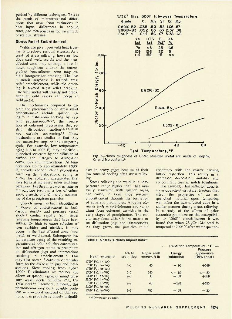
Toughness of chromium-molybdenum welds apparently decreases with increasing chromium content9 — Fig. 8. The primary reason for the reduced toughness may be that the increased chromium content increases the strength of the as-welded deposit. This will then impair the toughness.
Summation
The toughness of weld deposits in the as-welded condition is influenced by many factors. Composition has the greatest influence on toughness, although the effect of a particular element, whether a basic alloying element, tramp element, or dissolved gas, may be different in welds de-
I00r
"0 OAO 0.80 1.20 1.60 2.00 2 .40 2.80 Weight Percent A l l oy i ng Element
Fig. 6—Effect of alloy additions on notch toughness and hardness of submerged arc weld metal17
100
9 0
- 80
TO
ISO
^ri40
in 10 0
~ 60
2 . 4 0 2 .80 -60
0.40 0.80 1.20 1.60 2.00 Weight Percent Al loying Element
Fig. 7—Effect of alloy additions on notch toughness and hardness of gas-shielded arc weld metal17
362-s | A U G U S T 1971
posited by different techniques. This is the result of microstructural differences that arise from variations in heat input, differences in cooling rates, and differences in the magnitude of residual stresses.
Stress Relief Embrittlement Welds are given postweld heat treat
ments to relieve residual stresses. As a result of stress relieving, however, low alloy steel weld metals and the heat-affected zone may undergo a loss in notch toughness and/or the coarsegrained heat-affected zone may exhibit intergranular cracking. The loss in notch toughness is termed stress relief embrittlement, while the cracking is termed stress relief cracking. The weld metal will usually not crack, although cold cracks can occur in weld metal.
The mechanisms proposed to explain the phenomenon of stress relief embrittlement include quehch aging,11' 10 dislocation locking by carbide precipitation28' 20, the formation of coherent precipitates that restrict dislocation motion12' lC' 30' 31
and carbide coarsening.10 These mechanisms are similar in that they are successive steps in the tempering cycle. For example, low temperature aging (up to 400° F) may embrittle a quenched structure by the diffusion of carbon and nitrogen to dislocation cores, jogs and intersections. At temperatures up to approximately 1000° F, carbide and/or nitride precipitates form on the dislocations, acting as nuclei for coherent precipitates that may form at increased times and temperatures. Further increases in time or temperature result in a loss of coherency, growth, and ultimately coarsening of the precipitate particles.
Quench aging has been identified as a source of embrittlement in both carbon steels1' and pressure vessel steels10 cooled rapidly from stress relieving temperatures that have been sufficiently high to cause solution of iron carbides and nitrides. It may occur in the heat-affected zone, base metal, or weld metal. Subsequent low temperature aging of the resulting supersaturated solid solution causes carbon and nitrogen atoms to precipitate on dislocation jogs and intersections resulting in embrittlement.11 This may also occur if carbides or nitrides form on the dislocation jogs and intersections. Slow cooling from above 1200° F eliminates or reduces the effects of quench aging in many pressure vessel steels including 2 1 / 4 Cr-lMo steel.10 Therefore, although this phenomenon may be a possible problem in as-welded material of thin sections, it is probable relatively insignifi-
5 / 3 2 " Size, 3 0 0 F Interpass Temperature
Grade C Mn SI Cr Mo
E 8 0 I 6 - B 2 .038 .80 .52 1.08 .57 E9CH6-B3 . 0 5 2 .83 .63 2.571.08 E 5 0 2 - I 6 . 0 4 4 .86 .67 5.38 .62
YS ksi
UTS El RA ksi % 2 " %
I 0 0 r
78 9 3 25 6 5 109 126 2 0 51 114 138 15 4 4
• 4 0 0 4 0
Test Temperature,*F Fig. 8—Notch toughness of Cr-Mo shielded metal arc welds of varying Cr and Mo contents9
cant in heavy gages because of their low rates of cooling after stress relieving.
Stress relieving the weld in a temperature range higher than that normally associated with quench aging can cause, in some alloy systems, embrittlement through the formation of coherent precipitates. Alloying elements such as molybdenum and vanadium form coherent carbides in the early stages of precipitation. The nuclei may form either in the matrix or on dislocation jogs and intersections. As they grow, the particles retain
coherency with the matrix causing lattice distortion. This results in a decreased dislocation mobility and concomitant loss in notch toughness.
The as-welded heat-affected zone is an as-quenched structure. Factors that affect the properties of an as-quenched material upon tempering will affect the heat-affected zone in a similar manner during stress relieving. In a study of the effects of prior austenitic grain size on the susceptibility to "500F" embrittlement it was found that when 2V4Cr-lMo steel is tempered at 700° F after water quench-
Table 5—Charpy V-Notch Impact Data36
Transition Temperature, ° F Fracture
Heat treatment"
1750° F/l hr-WQ 700° F/l hr-WQ
1750° F/l hr-WQ 1300° F/l hr-WQ 2300° F/l hr-WQ 2300° F/l hr-WQ 720° F/l hr-WQ
2300° F/l hr-WQ 1310° F/l hr-WQ
ASTM grain size
6-7
6-7 2-3
2-3
2^3
Upper s energy,
45
140 30
45
200
helf ft-lb
Energy (midpoint)
+ 90
< - 80 + 50
+135
- 15
appearance (50% shear)
+165
< - 80 +100
+180
- 20
;i WQ—water-quench.
W E L D I N G R E S E A R C H S U P P L E M E N T ! 363-s

Table 6—Charpy V-Notch Data for Simulated Heat-Affected Zones- Several Low Alloy Steels1
Temperature for 50% fibrous — fracture appearance
- Charpy V energy at +20° C, ft-lb
Steel heat-af fected zone
s imulat ion '1
Mn-Cr-Mo-V S.A.F.G. S.A.C.G. M.F.G. M.C.G. S.A.F.G. | S.A.C.G. ( Restra ined M.C.G. { on cool ing M.F.G. J Mn-Cr-Mo-V M.C.G.
(h igh carbon) Mn-Ni-Cr-Mo M.C.G.
M.F.G. Mn-Mo M.C.G. Ni-Cr-Mo-V M.C.G. A l grain ref ined C-Mn
M.C.G.
Code
A
B C
D E
F
Base metal
- 1 5 - 1 5 - 1 5 - 1 5 - 1 5 - 1 5 - 1 5 - 1 5
+30 +10 +10
— + 10
- 5
As-we lded
+30 + 4 8 +18 - 1 0 +23 + 4 6 - 5 +10
+60 + 4 0 +50 + 10
0
- 3 0
. 3 hr,
842° F
+82 +98 +50 +55 +52 +80 +50 +38
+45 +40 +10 +30 - 1 5
—
Stress re 3 hr,
1022° F
+ 74 +108 + 62 +100 + 50 + 93 +106 + 60
+120 + 10 - 35
0 + 10
- 40
ief 3 hr,
1200° F
+ 55 + 74 + 16 + 26 + 36 + 60 + 40
+ 4
+ 20 - 80 - 1 0 5 - 60
0
—
Base metal
>140 >140 >140 >140 >140 >140 >140 >140
50 95 95
— 100
80
As-welded
43 26 35 35 35 30 40 35
15 35 20 40 45
>120
. 3 hr,
842° F
18 9
17 15 20 10 22 20
20 25 75 30 45
—
Stress re 3 hr,
1022" F
18 9
17 10 22 8 8
13
10 65
130 65 35
>130
lief - , 3 hr,
1200° F
20 11 35 27 26 18 31 43
40 140 175 110 45
—
' Simulat ing: S.A.F.G.—submerged-arc fine grain structure; S.A.C.G.—submerged-arc coarse grain structure; M.F.G.—manual weld fine grain structure; M.C.G.— manual weld coarse grain structure.
ing from 1750 or 2300° F, the impact energy transition temperature is higher than that of the as-quenched material.1"' This has been attributed to the formation of coherent MoX. Above the transition temperature, the upper shelf energy absorbed is greater for the tempered material than for the as-quenched material; however, as shown in Table 5, no effect of austeni-tizing is seen in these data. To show that other steels suffer from this same phenomenon, Charpy V-notch data for a simulated coarse-grained heat-affected zone in four different low alloy steels are listed in Table 6. Stress relief embrittlement occurs in three of the steels listed. Apparently Mn-Ni-Cr-Mo steel does not stress relief embrittle.
Precipitate strengthening of the matrix and grain boundaries in the heat-affected zone reduces the ability of the heat-affected zone to plastically deform by creep during stress relieving.*2 Intergranular cracking may result if the stress and temperature conditions are in the creep embrittlement range. Murray33 showed that materials exhibiting brittle behavior in stress relaxation are also prone to stress relief cracking. Swift34 investigated stress relief cracking in 2V4Cr-lMo steel, correlating the cracking with embrittlement resulting from dislocation locking and coherent precipitation. During stress relief the ductility in the heat-affected zone is reduced315 possibly through the operation of these two mechanisms.30
Since the high stresses in the weld zone are relaxed to the yield strength of the material at the stress relieving temperature, cracks will develop if the heat-affected zone cannot plastically deform by creep as proposed by Murray.33
Trends similar to those found in stress relief embrittlement of plate material have also been observed in certain weld metals.12- 13- 3S Puzak and Pellini'2 studied the characteristics of embrittlement in Ni-Mo-V and Mn-Mo weld metals. The latter, while exhibiting embrittlement when stress relieved below 1050° F, had 15 ft-lb transition temperatures well below —50° F. The kinetics of embrittlement in the Ni-Mo-V weld metal follow a ' C curve relationship reflecting a precipitation-induced phenomenon. Recovery occurs with time at higher temperatures indicating overaging— Fig. 9.
Wentworth and Campbell also studied stress relief embrittlement in Ni-Mo-V weld metals.13 If the weld metal had been stress relieved at temperatures above the embrittling range, then embrittlement was prevented during a subsequent heating in the embrittling range. Furthermore, no embrittlement occurred when a normalized and tempered weld was subjected to a thermal cycle that caused stress relief embrittlement in the as-welded condition. From this, Wentworth and Campbell concluded that stress relief embrittlement is caused by carbide precipitation from the supersaturated solid solution in the as-welded deposit.
Other examples of the sensitivity of weld metals to stress relief embrittlement are shown in Tables 1 and 7. In every instance stress relieving at 1100" F results in severe degradation of notch toughness. In the series of tests outlined in Table 7, the submerged arc welds exhibit slightly less embrittlement than do the welds deposited by shielded metal arc and gas metal-arc techniques. However, em
brittlement varies within each series depending upon electrode or filler metal flux combination.
Bland7 studied the effects of postweld stress relief on the hardness and ductility of 2V4Cr-lMo and lV4Cr-1/.JMo weld metal. His results are summarized in Table 8. Stress relieving 2V4Cr-lMo weld metal at 1050° F causes severe embrittlement. At 1150J F moderate embrittlement occurs after short times. Stress relieving at 1 150° F for over 2 hr/in. of thickness eliminates embrittlement. Stress relieving at temperatures in the 1250-13503 F range did not cause embrittlement for even short times. For lVjCr-V^Mo no embrittlement is observed for stress relieving temperatures as low as 1150° F. Preheating does not eliminate embrittlement although, with increasing preheat temperature, the severity of embrittlement is reduced. In all cases secondary hardening accompanies embrittlement.
The effects of composition on stress relief embrittlement of gas tungsten-arc weld deposits have been studied by Savas et al.39 for 9Ni-4Co steel and by Dorschu and Stout17 for mild steel. Carbon, manganese, nickel and silicon were found to have similar effects despite the large composition and structural differences in the weld deposits. This may be indicative of the general nature of the effects of these elements. Savas et al. found no effect of chromium and a beneficial effect of vanadium at low concentrations ( .15%). Within the composition ranges studied, however, carbon, nickel and vanadium have no effect on stress relief embrittlement. Chromium appears to be beneficial at concentrations above .15%, but manganese, co-
384-s | A U G U S T 1971

Table 7—Results of Charpy Impact Tests on Weld Metal Joinii
Welding process
Shie lded metal-arc
Submerged-arc
Gas metal-arc
Electrode or f i l le r metal - f lux
combina t ion
E9015-D1 (Mn-Mo)
E11018-G (Mn-Ni-Cr-Mo)
E12015-G (Mn-Ni-Cr-Mo-V)
Linde 100 f i l le r metal and Un ionme l t 709.5 f lux
Linde 103 f i l le r metal and Un ionme l t 103 flux
Lincoln L-61 f i l ler metal and A0905X10 al loy f lux
Airco A632 f i l le r metal and argon plus 1 % oxygen
Arcosarc HOT flux-cored f i l le r metal and C02 gas
Preheat and
interpass
tempera tu re ,
° F (° C)
70(21)
70(21)
70(21)
70(21)
70(21)
70(21)
200(93)
200(93)
300(149)
300(149)
200(93)
200(93)
350(177)
350(177)
70(21)
70(21)
200(93)
200(93)
- Condi t ion of weld metal
As-welded
Stress-rel ieved at 1100° F (593° C)
As-welded
Stress-rel ieved at 1100° F (593° C)
As-welded
Stress-rel ieved at 1100° F (593° C)
As-welded
Stress-rel ieved at 1100° F (593° C)
As-welded
Streess-rel ieved at 1100° F (593° C)
As-welded
Stress-re l ieved
at 1100° F (593° C)
As-welded
Stree-rel ieved qt1100° F (593° C)
As-welded
Stress-re l ieved at 1100° F (593° C)
As-welded
Stress-re l ieved at 1100° F (593° C)
ng T - l Steel38
— Ti Charpy
keyhole m i d -
envelopei
- 1 5 5 ( - 8 2 )
- 8 3 ( - 6 4 )
8
•
- 7 8 ( - 6 1 )
Above +130 ( - 5 4 )
a
- 2 2 0 ( -140)
- 1 6 0 ( -107)
- 1 6 4 ( -109)
- 1 5 0 - ( 101 )
- 1 3 2 ( - 9 1 )
a
- 1 2 9 ( - 8 9 )
- 5 ( - 2 1 )
- 2 3 4 ( -151)
- 1 1 0 ( - 7 9 )
-ansit ion 1 . Ch
10 f t - lb (1.7
mkg/cm2 )
- 1 2 8 ( - 8 9 )
- 1 5 6 ( -104)
- 9 6 ( -71 )
- 4 0 ( - 4 0 )
a
a
- 1 2 6 ( - 8 8 )
- 5 2 - ( 4 7 )
- 175 ( -115)
- 1 0 2 ( - 7 4 )
- 1 4 8 ( -100)
- 5 6 ( - 4 9 )
a
- 1 4 8 ( -100)
- 5 6 ( -49 )
temperat i j r e , ° F (° arpy V-notch —
15 f t- lb (2.6
mkg /cm 2 ;
- 1 0 0 ( - 7 3 )
a
- 1 1 6 ( - 8 3 )
- 5 2 ( - 4 7 )
4 ( -16 )
a
- 8 4 ( - 6 4 )
- 1 2 ( - 2 4 )
- 1 4 8 ( -100)
- 8 4 ( - 6 4 )
- 1 0 2 ( - 7 4 )
—28 ( - 2 )
a
- 1 0 6 ( - 7 6 )
- 3 4 ( -37 )
30 f t - lb (5.2
imkg/cm 2 '
- 5 8 ( - 5 0 )
a
- 3 2 ( - 3 6 )
24 ( - 4 )
» ; i
a
8 ( -13 )
58 (14)
- 9 5 ( -71 )
- 4 8 ( - 4 4 )
- 2 0 ( -30 )
50 (10)
- 7 0 ( - 5 7 )
a
- 4 7 ( - 4 4 )
26 ( - 3 )
C) —
50% shear
) f rac ture
- 3 8 ( - 3 9 )
a
- 6 0 ( - 5 1 )
20 ( - 7 )
24 ( - 4 )
a
a
6 ( - 1 4 )
84 (29)
- 7 8 ( -S1)
- 2 5 ( - 3 2 )
- 4 4 ( - 4 2 )
26 ( - 3 )
a
- 7 4 ( - 5 9 )
14 ( -10 )
Averag-abso
e energy rpt ion
v—ft-lb (mkg/cm 2 )—. Charpy
keyhole - 5 0 ° F
( - 4 6 ° C)
Charpy V-notch - 5 0 ° F ( -46° C)
Above 28 33 (7.7)
33 (9.1)
a
a
26 (7.2)
a
a
28 (7.7)
24 (6.6)
41 (11.3)
34 (9.4)
20 (5.5)
a
33 (94)
15 (41)
30 (83)
23 (53)
(5.7) a
27 (4.7)
17 (2.9)
10 (1.7)
a
21 (3.6)
18 (3.1)
19 (3.3)
11 (1.9)
53 (9.2)
29 (5.0)
23 (4.0)
11 (2.9)
49 (85)
a
29 (50)
12 (2'1)
" Not determined.
bait, silicon, phosphorus and sulphur are all detrimental.
Summation
Except for the data of Bland,7
there is little information on the magnitude of stress relief embrittlement in
2V4Cr-lMo weld metal specifically. In general, embrittlement can be minimized by maintaining a high purity deposit and utilizing the proper welding process. Gas metal-arc and gas tungsten-arc welds hold the most promise because of the close control
of composition and purity that can be obtained. However, these processes are uneconomical for heavy wall construction. Submerged arc welding appears to be the next best choice for producing a weld that can be properly stress relieved.
W E L D I N G R E S E A R C H S U P P L E M E N T ! 365-s

Table 8—Effect of Time and Temperature on Hardness and Du Welds Made in.234 Cr-Mo Steel Pipe Using Various
• Thermal Treatment Electrode Preheat, Postheat,
brand ° F ° F H
Code A None As-welded 2K Cr-1 Mo 1050
1150
1250
1350
300 As-welded 1050
1150
1250
1350
500 As-welded 1150
1250
1350
Code E None As-welded VA Cr-y2 Mo 1150
1250
300 As-welded 1150
1250
500 As-welded 1150
1250
w
, ours
— 1 4
16 1 2 4 8 1 2 4
y% 1 2
— 1 4
16 1 2 4 8 1 2 4
H l 2
— l 2 4 8 1 2 4 1 2
— A
1 2 4
% 1 2
— Vi 1 2 4
¥2 1 2
— H
1 2 4
H 1 2
Electrodes' ctility ol
— Brinell hardness" —. . Weld
avg
235 276 276 276 255 265 245 216 216 200 200 200 200 190 235 265 265 255 255 245 235 216 210 200 200 190 190 180 231 255 245 245 228 210 210 190 190 190 222 216 228 207 200 207 198 185 213 216 224 207 207 204 198 198 220 221 216 210 198 200 192 180
HAZC
avg
245 255 255 255 228 216 216 210 200 180 176 190 176 180 213 235 235 245 235 210 210 200 180 180 190 176 180 169 210 235 235 216 200 210 200 169 180 176 230 238 231 220 200 207 198 185 234 220 243 210 204 207 185 188 250 234 238 192 210 195 195 192
Pipe avg
144 139 139 139 135 135 135 135 135 130 135 135 135 135 139 139 139 135 135 135 130 130 130 130 135 130 135 135 135 135 135 130 135 135 130 130 135 135 141 136 138 138 137 141 141 137 143 137 137 136 136 141 138 136 143 138 140 136 137 138 141 137
— Ductility1' —, Weld
avg
14.2 4.7 4.7 4.7 9.7 7.3
12.3 19.4 19.4 23.4 23.4 23.4 23.4 25.9 14.2
7.3 7.3 9.7 9.7
12.3 14.2 19.4 20.9 23.4 23.4 25.9 25.9 28.3 15.8
9.7 12.3 12.3 16.5 20.9 20.9 25.9 25.9 25.9 21.6 22.4 20.9 23.5 24.4 23.5 24.6 25.3 22.8 22.4 21.3 23.5 23.5 23.9 24.6 25.9 21.9 21.9 22.4 23.1 24.6 24.4 25.4 26.9
HAZ" avg
22.9 22.3 22.3 22.3 23.8 24.5 24.5 24.8 25.4 26.5 26.7 25.9 26.7 26.5 24.7 23.4 23.4 22.9 23.4 24.8 24.8 25.4 26.5 26.5 25.9 26.7 26.5 27.1 24.8 23.4 23.4 24.5 25.4 24.8 25.4 27.1 26.5 26.7 23.8 23.3 23.7 24.3 25.4 25.2 25.1 26.3 23.5 24.3 23.0 24.9 25.2 25.1 26.3 26.1 22.6 23.5 23.3 25.9 24.9 25.7 25.7 25.9
;l Converted from Rockwell hardness values. b Elongation, % in 2 in. c HAZ—heat-affected zone.
Temper Embrittlement The severity of temper embrittle
ment is measured by the magnitude of the upward shift in the ductile-brittle transition temperature from its value
Above the transition temperature, however, there are no discernable differences between fractures in the embrittled or non-embrittled material. Hence, the upper shelf energy is usually not affected by temper embrittlement.23- 2 0 ' 4 0 - 4 2 Over the past few years the susceptibility to temper embrittlement of several grades of steel has been evaluated.10 It was found that long-term exposure at 700° F does not induce temper embrittlement in Cr-Mo steels. Another study,20
however, has since shown that isothermal aging at 950° F for only 750 hr can cause temper embrittlement. It is possible that either 700° F is below the temper embrittlement range for Cr-Mo steels or the kinetics of embrittlement is so slow at 700°F that the aging time was insufficient to cause embrittlement. Step cooling, a series of isothermal soaking treatments at progressively lower temperatures from 1100 to 600° F designed to accelerate temper embrittlement, was also found to cause embrittlement in nickel, chromium, nickel-chromium and chromium-molybdenum steels.25- 26> 40-43
The susceptibility of a steel to temper embrittlement is highly dependent on its composition, while the degree of embrittlement is determined primarily by its microstructure. The presence of trace amounts of known embrittling elements such as arsenic, antimony, tin and phosphorus alone is insufficient for embrittlement.23' 24 It is also necessary that other specific alloying elements be present. For example, Low et al.*3 showed that a plain carbon steel with 0.06 to 0.08 antimony does not embrittle, but the addition of nickel and/or chromium causes severe embrittlement with up to a + 1256° F shift in transition temperature. Similar results were found for phosphorus, tin and arsenic.
The data of Low et al.*3 was used by Bruscato23 to develop a comparison factor, X, to which the temper embrittlement of 2V4 Cr-1 Mo steel weld metals can be related. The variable X is given by the following equation:
X = 10P + 5Sb + 4Sn + As ppm 100
(1)
in the unembrittled state. The latter may vary widely depending on composition microstructure. In temper embrittled steel the fracture follows the prior austenitic grain boundaries.
The concentration (in ppm) of each of the impurity elements in X is weighed according to its individual effect on temper embrittlement as determined by Low et al.Vi The embrittlement is measured by the Charpy V-notch energy absorbed at +50° F after step cooling. When this is plotted as a function of both X and the sum of Mn and Si concentration in wt-%, an interaction is seen.
366-s I A U G U S T 1971

I300r Recovered
-40 - 40 -70^^20—-^
Approximote A | Temper oture^.
- 40 Moderately Embrittled
-60
-40
90 Recovered -120
20
800 2 3 4 5 6 7 8 9 10 24 4 8
Holding T ime, Hours Fig. 9—Time-temperature zones of embr i t t l emen t and recovery for Ni-Mo-V weld deposit . The values shown ind icate Charpy-V 15 f t - lb temperature t rans i t ions (°F) for respect ive ho ld ing t imes and tempera tu re 1 2
The temper embrittlement of shielded metal arc welds in 2V4Cr-l-Mo steel has been investigated by Kerr.20 His data have been replotted in Fig. 10 as a function of X. The numbers above the points are the values of the energy absorbed after step cooling while the numbers below the points are the energies absorbed in the base condition. These data are for covered electrode welds and one heat of steel plate. Three separate strengths of the same heat of steel were tested and have three different energies in the base condition. After step cooling, however, the embrittled materials have comparable energies (Codes M, K and YY, Table 9) . Bruscato25 has shown that this type plot holds for welds deposited by a variety of welding processes and for different heats of base metal with a basic 2V4Cr-lMo composition. This type plot does not show the trends as clearly when the 40 ft-lb transition temperature is used instead of the energy absorption at +50° F.
The above discussion points out the importance of manganese, silicon, nickel and chromium in the enhancement of susceptibility to embrittlement. Molybdenum plays a dual role, however, in concentrations up to 0.5% molybdenum reduces embrittlement.23' 44 In higher concentrations molybdenum has little effect on embrittlement.
Microstructure influences susceptibility to embrittlement through both the transformation product and the prior austenitic grain size. Pearlite, bainite and martensite are respectively increasingly more susceptible to tem
per embrittlement -3 -45 as shown in Table 10. The shift in transition temperature caused by embrittlement increases as the transformation temperature decreases, since the maximum transition temperature for all embrittled structures appears to approach a single value. Table 11 compares the susceptibility to embrittlement of a quenched and tempered 2 1 / 4Cr-lMo steel with one that is normalized and tempered. Although the normalized and tempered structure appears to be less susceptible to temper embrittlement than a quenched and tempered structure, an embrittled quenched material may be tougher than a non-embrittled normalized and tempered material.
Fractographic studies have shown that temper embrittlement is accompanied by a change in brittle fracture
1.6
1.5
1.4
I.2H-* in
lu 2 ~I.O
mode from transcrystalline cleavage to a decohesion along prior austenite grain boundaries.41 In the less susceptible normalized and tempered structure, the ferrite-bainite boundaries are affected. This change in fracture mode confirms the existence of the temper embrittlement phenomenon although there is only a slight change in toughness.
Grain size also appears to affect susceptibility to temper embrittlement. In a nickel-chromium steel, Capus40 found that susceptibility increased as the grain size increased. He attributed this to a lower total energy required to create the new fracture surfaces in the coarse-grained material because of its smaller grain boundary area. Furthermore, since the fracture path is forced to change directions more frequently in a fine-grained ma-
0.9
0.8
25£
Plott
12 14 16 2-
24 26 18 20 22 IOP + 5Sb+4Sn-*A»
100 p p
Fig. 10—Effect of X factor on + 5 0 ° F Charpy V-notch energy of s tep cooled 2V* Cr- lMo steel weld meta l 2 5 - 2 B
W E L D I N G R E S E A R C H S U P P L E M E N T ! 367-s

Table 9—X Factor for Weld Metals and Plate— IV Cr-1 Mo Stee l"
Ul t imate tensi le Charpy V-notch energy at
s t reng th , +50° F, f t - lb Mater ia l
Weld Metal Weld Metal Weld Metal Weld Metal Weld Metal Weld Metal Weld Meta l Weld Metal Weld Metal Weld Metal Weld Metal Weld Metal Weld Metal Weld Metal Plate A0152 Plate A0152 Plate A0152
Code
A B C D E F G N 0 P S T X
z K M
YY
X
17.20 15.18 14.06 19.90 15.58 19.54 19.51 17.84 15.78 20.27 15.95 24.41 13.42 16.34 25.52 25.52 25.52
Mn + Si 1.53 1.52 1.42 1.29 1.39
.93 1.40
.83 1.00 1.35 1.07
.88 1.05 1.28
.91
.91
.91
ksi
— — — — — — — — — — — — — —
121.5 96.0 91.1
Base cond i t ion
75 70 85 90 90 70 50
125 125
85 110 95 80
120 20 45 55
Step cooled
15 25 48 33 35 42
8 88 70 15 65 15 70 95 25 20 25
Table 10—Effect of Microstructure on Susceptibility to Temper Embrittlement of Ni-Cr Steel23
Microst ructure
Pearl i te
Bain i te
Mar tens i te
Mar tens i te
Heat t rea tment
Austeni t ize 1652° F "Trans i t ion 1148° F Temper 1202° F, V2 hr Same plus 932° F, 32 hr Austeni t ize 1652° F
"Trans i t ion 662° F Temper 1202° F, }/2 hr Same plus 932° F, 32 hr Austen i t ize 1652° F Oil quench Temper 1202° F, 1 hr Same plus 932° F, 32 hr Austen i t ize 1652° F Oi l quench Temper 1202° F, 50 hr Same plus 932° F, 32 hr
Trans i t ion smperature,
0 F
+158 +250
+130 +323
- 75 +279
- 61 +133
Shi f t in t rans i t ion
tempera tu re , ° F
+ 92
+193
+354
+194
Vickers hardness
50 kg
214 210
257 253
280 278
223 220
• Temperature of short isothermal soak to allow for complete transformation.
terial, additional energy will be absorbed. In contrast, exploratory work on 2V4Cr-lMo plate material shows an apparent critical grain size for
maximum embrittlement.42 This is attributed to competition between two phenomena. As the grain size increases, the path length for the dif
fusion of embrittling constituents to the boundaries is increased, but the fracture path length is decreased. The discrepancy between these two studies may be due to differences in heat treatment. Capus varied the austeniz-ing temperatures to obtain different grain sizes, but allowed the material to equilibrate at 1560° F prior to quenching. Swift42 quenched directly from the different austenitizing temperatures.
The kinetics of embrittlement are determined by the nature of the responsible reactions. Most solid state reactions are controlled by the relation between the driving force and available thermal energy at any particular temperature, producing a ' C curve. laffe and Buffum47 showed that the temper embrittlement of SAE 3140 steel followed such a relationship. Their curves, including several corrections incorporated after the initial investigation,48 are shown in Fig. 11. The original study had indicated the existence of a double nose in the curves, the upper nose occurring in the 1150-1200° F range. laffe and Buffum felt that a possible cause of this nose may have been an inadvertent overtempering or softening. Carr et al.iS repeated the tests in this temperature range, compensating for changes in the transition temperature resulting from a loss in hardness, and did not find a double nose.
The most probable explanation of temper embrittlement is that the segregation of trace impurities to the surface of precipitates at prior austenitic grain boundaries promotes deco-hesion of the boundary between the precipitates and the ferrite matrix.24
There is considerable evidence to substantiate this theory. Restaino and McMahon24 analyzed the fracture surfaces of embrittled and nonembrit-tled steel chemically and found an increased concentration of antimony in the prior austenitic grain bound-
Table
1) 2) 3) 4) 5) 6) 7) 8) 9)
10)
11—Relative Sus
Refer-Codea ence
SS 26 II 26 ZZ 26 OO 26
41 41
M 26 YY 26 Y 26 WW 26
ceptibilities of Quenched and Normalized 2 ' 4
Heat no.
A6723 (QT) A6723 (NT) A2766 (QT) A2766 (NT) B6730 (QT) B6730 (NT) A0152 (QT) A0152 (QT) A0152 (NT) A0152 (NT)
UTS,b
ksi
87 73 87 76 84 68 96 91 86 83
Base cond i t ion 40 f t - lbs
( °F)
- 1 2 0 - 35 - 70 - 15 - 2 2 0 + 50 + 20 + 10 + 60 + 60
FATT ( °F )
- 15 + 25 - 35 + 55 - 1 0 0 + 75 + 55 + 40 + 80 + 70
UTS, ksi
85 72 86 73 90 — — 90 — 81
Cr-1 Mo Plate Material
Step cooled cor b 40 f t - lbs
(°F) - 20 - 40 - 35 - 30 - 1 5 0 - 10 + 95 + 80 + 60 + 40
A40 ( °F )
+100 - 5 + 35 - 15 + 70 - 60 + 75 + 70
0 - 20
id i t ion FATT
ro + 80 + 35 + 40 + 40 - 80 + 90 +120 +120 + 70 + 90
A FATT ( ° F )
+95 +10 +75 - 1 5 +20 +15 +65 +80 - 1 0 +20
6 in . 6 in . 6 in. 6 in. 1 in. 11 ir 6 in . 6 in . 6 in. 6 in.
Remarks 0
s imu la t i on (WQ) s imu la t i on (AC) s imu la t ion (WQ) s imu la t ion (AC) water quench
i. s imu la t ion (AC) s imu la t i on (WQ) s imu la t ion (WQ) s imu la t i on (AC) s imu la t i on (AC)
a Refers to code used in reference. b UTS—ultimate tensile strength. c WQ—water quench; AC—air cool.
368-s I A U G U S T 1 9 7 1

Fig. 11 — Iso-embrittlement curves of Jaffe and Buffum47
plotted as a time-temperature diagram for SAE 3140 incorporating corrections of Carr48
1200
1100
1000
900
8 0 0
7 n n
•
•
V • C / Corrected •S -NV>Q Transition ^ ^ Temperature »5F
" «-76 T - 6 7 0-58 • -49 D-40
' ©-31 A-22 a-13 y - 4 • 1
v 14 D 23 • 32 0)41 • 50 6 59 A 68 0 7 7 n 86
1 1
•
•
•
• U • a
•
'
0 a u r. v v w^->
O
o • a •*
__»•
( — i
^ V f 4 (0-<y lIlsKL
1 I V " ^ ^ N N • O.I 0.5 1.0 5.0
Embri t t l inq Ti 10 me Hrs
5 0 | 0 0 5 0 0
aries of the embrittled material. More recently, Marcus and Palmberg,49
using Auger electron spectroscopy, showed that antimony had segregated to the intergranular fracture surface of embrittled AISI 3340 steel. They also studied the extent of segregation in AISI 5140 steel. By removing successive layers from the surface by sputtering and analyzing them, Marcus and Palmberg showed that the segregation is confined to a few atom layers at the surface.50
A less widely accepted theory of temper embrittlement is based upon dislocation locking. Internal friction measurements show a damping peak in a temper embrittled steel which is lacking in a non-embrittlement steel of the same composition.51 The authors feel this is closely related to the incidence of temper embrittlement, but no clearly defined mechanism is proposed. Banerjee28 has correlated dislocation locking with the incidence of "500F" embrittlement. This form of embrittlement is non-reversible in that once eliminated it does not recur unless the material is reaustenitized. Perhaps the thermal treatments that induce temper embrittlement may cause dislocation locking but this locking is not the predominant embrittlement mechanism.
Summation
The effects of the welding process and parameters on temper embrittlement have only recently been investigated, and available data are fragmentary. Based upon information for plate material, it is apparent that any
welding process that produces a relatively pure deposit such as gas tungsten-arc or gas metal-arc will be least susceptible. Nevertheless, Bruscato25
and Kerr20 have shown that by tailoring the chemistry to reduce the level of trace impurities, a weld with a low susceptibility to temper embrittlement can also be produced by a shielded metal arc weld. A low energy input is desirable to minimize grain coarsening in multipass welds thereby reducing susceptibility. However, until a comprehensive study has been made, the complete influence of the welding process will not be known.
Creep Embrittlement When a specimen or structural
member is subjected to stress-temperature conditions conductive to creep, creep embrittlement may occur. It is manifest by an abnormal decrease in the rupture ductility followed by an increase in rupture ductility with decreasing stress or increasing time to rupture. This phenomenon has been observed in low alloy steels,35- 52~Si
stainless steels,53' °5 carbon steels with a high concentration of active nitrogen53 and certain nonferrous alloys.56"58 The loss in rupture ductility is coincident with the appearance of intergranular fracture associated with microvoid coalescence in the grain boundaries.35' 53- 58~61 The subsequent increase in rupture ductility is associated with the formation of a denuded zone adjacent to the grain boundaries :i5' 5S' 58> e2 ' °6
Purity is an important factor in determining susceptibility to creep
embrittlement. It is believed that impurities, such as arsenic, antimony, tin and phosphorus, segregate to the prior austenitic grain boundaries and are absorbed on the matrix-precipitate interfaces, either weakening the atomic bonds between the matrix and precipitate55 or breaking them completely."2 During creep, grain boundary sliding can cause these weakened bonds to rupture with relative ease. As a result, a void develops at the interface between the matrix and intergranular precipitate and a low ductility rupture occurs. However, with increasing purity, ductility increases because grain boundary sliding can occur without the formation of these voids.53' 58' 59
Impurities can also affect creep ductility by enhancing strain aging in the matrix. At high temperatures the application of a stress normally causes either grain boundary sliding or grain boundary migration. Grain boundary migration does not contribute to the total creep strain,61 but serves to relax elastic strains across the grain boundaries by acting as a sink for dislocations. This improves the creep ductility. Grain boundary migration may also improve ductility by removing the sliding interface, i.e., the grain boundary, from creep damaged areas.
If the matrix is strengthened by strain aging, it is less able to plastically deform, concentrating the strain at the weaker grain boundaries. This promotes the grain boundary sliding mode of deformation. Strain aging, by strengthening the matrix, also may retard grain boundary migration. This
W E L D I N G R E S E A R C H S U P P L E M E N T ! 369-s

affects creep ductility because the relaxation of elastic strains in the region of the boundaries is prevented, allowing local strain to accumulate. The result is a low ductility fracture.
Strong or brittle intergranular precipitates may also reduce rupture ductility. Because precipitates cannot plastically deform to accommodate the matrix strains arising from the relative motion of material across a grain boundary, they nucleate brittle intergranular fracture.04 Frequently, zones denuded of alloying constituents form adjacent to the grain boundaries.35' 61> 64~0C In solid solution strengthened alloys such as 18 Cr-12Ni-lCb, the zone becomes depleted of its solid solution strengthening elements.64 In alloys that derive their strength from precipitates such as 2 1 / 4Cr-lMo steel, this zone becomes depleted of its precipitates.35'" 63, 66, 66 Normally, when the dispersion of precipitates is relatively uniform, the creep strain is partitioned between the matrix and grain boundaries in accordance with their relative strengths. Transgranular fractures with high ductility result. As the time to rupture increases, grain boundary precipitation increases relative to matrix precipitation. The alloy elements that precipitate in the boundary diffuse from the matrix thereby depleting the matrix of the solid solution elements in the zone adjacent to the boundary.
Precipitates adjacent to the grain boundaries dissolve in order to replace the solid solution alloying elements that have precipitated in the grain boundaries. This process rapidly depletes the zone near the grain boundary of its precipitates, leaving this region with lower creep strength than the matrix or the grain boundary itself. Under stress, creep deformation will tend to be concentrated within this denuded zone. The effect of a denuded zone in precipitation-hardening alloys depends on the width of the zone.50' °2- m- 06 If the zone is narrow, it can accommodate only a limited shear displacement because its shear strain will then be high. A low ductility intergranular fracture then results. As the zone width increases, a much greater plastic shear displacement can be accommodated at an equivalent shear strain in the zone, increasing the ductility.35- 53- 50' 62_
65,66
Creep ductility in low alloy steels is influenced by the amount of soluble aluminum present. A study of vacuum outgassed Cr-Mo-V steels67 showed that rupture ductility decreased as the concentration of soluble aluminum increased. The concentration of soluble
aluminum was assumed to reflect that part of the total aluminum content not tied up with nitrogen in the form of A1N. Thus, for a fixed nitrogen content, a reduced concentration of A1N indicates an increased amount of nitrogen available to cause strain aging53 which decreases the rupture ductility.
The concentration of carbide forming elements in solid solution also affects the rupture ductility. In a Cr-Mo-V steel the severity of creep embrittlement has been found to increase as the concentration of molybdenum and vanadium in solid solution increased.68. After austenitizing at 1920° F and air cooling, the resulting ferrite is more highly supersaturated with molybdenum and vanadium than when austenitized at 1760° F and air cooled. This includes both proeutectoid and bainitic ferrite. Tempering produces a fine dispersion of carbides in the material austenitized at the higher temperature. This fine precipitate dispersion markedly reduces the rupture ductility.
A quenched and tempered structure has better initial creep strength than a normalized and tempered structure although the latter has a greater rupture ductility.59. 63 This is attributed to the greater resistance to flow afforded by the finer dispersion of precipitated carbides usually found in a quenched and tempered material. In a normalized and tempered material the carbides are usually coarse, offering little resistance to plastic flow; they are, however, generally more stable than the fine carbides found in a quenched and tempered structure. Pickering59
suggests that as the stability of the precipitated carbides increases, less intergranular cavitation will occur during creep. This is attributed to a reduced matrix strength relative to that of the grain boundaries. Those elements that would act as solid solution strengtheners of the matrix, such as molybdenum, are effectively prevented from acting since they are retained in the stable carbides.
The prior austenitic grain size of a quenched and tempered 2 !/4Cr-lMo steel has a marked effect on its rupture ductility without an apparent commensurate effect on its rupture life.03 Increasing the prior austenitic grain size from ASTM 6 to ASTM 2 caused a decrease in the reduction in area from 35 to 10% at the creep ductility minimum despite the fact that stress rupture curves are nearly coincident. This loss in rupture ductility with increasing grain size is attributed to the reduced contribution of grain boundary sliding to the total strain.
Numerous tests on Cr-Mo steels have established the existence of creep embrittlement in both steel plate and weld metal.35' 52. 54> 09- ™"72 Tests on quenched and tempered plate material with room temperature tensile strengths ranging from 104 to 149 ksi and on weld metal in the as-welded, stress relieved, or quenched and tempered condition with strengths up to 134 ksi show a strong effect of strength level, carbon content and welding process on the degree of creep embrittlement. Figure 12 5 4 ' 6 9
shows the effect of both strength level and carbon content on the rupture ductility of quenched and tempered plate. At strength levels above 130 ksi, the rupture ductility clearly decreases with increasing strength; however, at strength levels lower than 130 ksi, strength level has no significant effect on rupture ductility. Carbon appears to reduce the rupture ductility at high strength levels as seen in curves 5 and 6. Of the two materials, the one in curve 6 has a higher ductility probably due to the combination of lower strength and lower carbon content.
In addition to the factors that determine rupture ductility in plate material, the ductility of weld metal is also affected by the welding process. Figure 13 shows the effect of welding procedure, postweld heat treatment and strength on the rupture ductility of 2 1 / 4Cr-lMo weld metal. Curves (1-6) show the effect of stress relieving and carbon content on the rupture ductility of shielded metal arc welds.52 In all cases stress relieving raises the rupture ductility minimum. The high carbon welds (curves 3 and 6) show a greater improvement in ductility after stress relieving than do the low carbon welds. The available data do not indicate any effect of electrode coating on the rupture ductility.1' 2' 4' 5. The stress relieved submerged arc welds (curves 7 and 8) have poorer rupture ductilities than the quenched and tempered submerged arc welds (curve 9) . On the surface, the electroslag welds appear to have better ductility than the submerged arc welds; but if quenched and tempered submerged arc and electroslag welds at the same strength level are compared (curves 9, 10), the submerged arc weld has the greater rupture ductility.
Bruscato has found that temper embrittling heat treatments prior to creep stressing improved the subsequent rupture ductility of 21 /4Cr-lMo shielded metal arc welds.25 This is interpreted as meaning that creep embrittlement as well as temper embrittlement involves trace impurities;
370-S ( A U G U S T 1971

lOOr
Fig. 12—Effect of strength level and carbon content on rupture ductility of 2V4 Cr-lMo plate materials54. 69
27
JL MIS REF 1 O .15 I04ksi 54 2 •.15 I22ksi 54
69 SS 69 69
28 29 30 31 32 33 34 35 Larson-Mi l ler Parameter CP= T ° R ( 2 0 + l o g t p x IO"3
37
Fig. 13—Rupture ductility vs. Larson-Miller parameter for 2V4 Cr-lMo weld metal5 2 .7 0 .7 2
Type and Condition Ref I O E 9 0 I 6 - B 3 L
2 e E 9 0 1 8 - B 3 L 3<DE90I5- B3H 4 • E 9 0 I 6 - B3L 5 © E 9 0 I 8 - B 3 L 6 OE9 0I5- B3H 7 • Sub-Arc 6" 8 B Sub-Arc 4" 9 B Sub -Arc 4 "
I 0 # Electroslag 11 <S Electroslag 12 O Electroslag
(SMA) AW (SMA) AW (SMA) AW (SMA) SR (SMA) SR (SMA) SR 135 ksi SR I35ksi SR I28ksi QT I2 8ksi QT 115 ksi QT I08ksi QT
S2 52 52 52 52 52 71
\\ 70 79 72
26 28 30 32 34 36 38 Larson-Miller Parameter CP= T°R(20+ log t )3 x lO" 3
therefore, subjecting the material to a prior temper embrittling treatment will tie up the impurities in some manner so that they are available to cause creep embrittlement.
Summation
Creep embrittlement is influenced by many factors. Strength, carbon content, grain size, degree of solid solution strengthening and precipitate morphology contribute to creep embrittlement. For maximum ductility, a normalized and tempered structure is preferable; nevertheless, a quenched and tempered, or welded plus stress relieved structure might be more desirable because of its greater creep strength.
Summary There is evidence in the literature
that stress relief embrittlement, creep embrittlement and temper embrittlement may be related. The existence of a relationship is by no means conclusive, because few investigators have studied these forms of embrittlement concurrently. The degree of embrittlement increases with increasing prior austenite grain size for all three forms
of embrittlement both in weld metal and plate steel. In plate, stress relief embrittlement occurs in the heat-affected zone during postweld heat treatments and can be manifest by intergranular cracking and a loss in notch toughness. For susceptible weld metal, embrittlement is usually manifest by a loss in notch toughness.
The susceptibility to embrittlement is also a function of strength level. Stress relief and creep embrittlement are more severe at higher strength levels; temper embrittlement, however, appears to be more pronounced at lower strength levels. Considerable evidence exists that stress relief embrittlement and creep embrittlement at least depend partially on precipitate formation during thermal processing or testing. Temper embrittlement is primarily the result of the segregation of trace impurities to prior austenite grain boundaries. For a given composition, the transition temperature in the embrittled state is approximately the same for all structures. The shift in transition temperature, which is used as the measure of temper embrittlement, is therefore greater for structures having lower strength levels. Al
though the susceptibility to temper embrittlement may be more acute at low strength levels, the energy absorbed at +50° F for embrittled 21 /4Cr-lMo appears to be independent of strength. The degree of embrittlement can be estimated from a plot similar to that in Fig. 10.
Purity appears to affect all three types of embrittlement in weld metal. Increasing purity reduces the susceptibility both to creep embrittlement and temper embrittlement. Although there has been no study on the effect of purity on the stress relief embrittlement of welds, scattered information in the literature indicates that "500° F " or "tempered martensite" embrittlement are reduced by increasing the purity. Impurity effects are superimposed on the embrittling effects of coherent precipitates, the locking of dislocations by carbide precipitates, and denuded zone formation at grain boundaries. Impurities may interact with the precipitation phenomenon, enhancing the embrittlement. A complex interaction of impurities with alloy elements is known to occur in temper embrittlement. A similar interaction may occur with the other
W E L D I N G R E S E A R C H S U P P L E M E N T [ 371-s

forms of embrittlement. The influence of welding parame
ters on each type of embrittlement has not been examined extensively. Furthermore, no correlation between the susceptibility to embrittlement and the type of welding process appears in the literature. The correlations that have been made are between embrittlement and the process parameters and weld metal purity. Based upon available information, a lower heat input will generally reduce embrittlement.
In spite of the many studies of the various types of embrittlement, no well established correlations have been generated nor have the mechanisms been clearly identified. The work on 21 /4Cr-lMo has consisted principally of testing creep-rupture properties, but little attempt has been made to study notch toughness. Within the past five years interest has increased, but as yet no mechanistic studies of the factors affecting notch toughness of 2V 4
Cr-1 Mo steel and weld metal have been conducted.
Acknowledgments
The authors would like to acknowledge the sponsorship of the Pressure Vessel Research Committee of the Welding Research Council and the assistance and encouragement given to one of the authors (R.A.S.) by E. L. Fogleman and J. A. Gulya of Lukens Steel Company, Research Center, during the course of preparing this survey.
References 1. Carpenter , O. R., and Floyd, C , " Im
po r t an t Considerat ions for the Welding of Chromium-Molybdenum Stee ls , " West of Scotland I ron and Steel Ins t i tu te , October 1956. 124-156.
2. Nesbitt,- L. C , "Weld ing High Tempe r a t u r e High P res su re P ip ing Wi th Chrome-Moly Elec t rodes , " WELDING JOURNAL 35(2), 129 to 136 (1956).
3. Smith, D. C , "Development , P roper ties and Usabi l i ty of Low-Hydrogen Elect rodes , " Ibid. 38(9), Welding Research Suppl. , 377-s to 329-s (1959).
4. L inner t , G. E. , "Selection of Fi l le r Metals for Weld ing , " Welding High Strength Steels, ASM, Metals P a r k , Ohio 1969.
5. Gross, J . H., "New Developments in Steel We ldmen t s , " WELDING JOURNAL, 47 (6), Welding Research Suppl. 241-s to 270-s (1968).
6. Stout , R. D., McLaughl in , P . F . , and Strunck, S. S., " H e a t T r e a t m e n t Effects of Mult iple-Pass Welds , " Ibid., 48(4). Welding Research Suppl. , 155-s to 160-s (1969).
7. Bland, J., " T h e Arc Welding of 2.25% Cr-l%Mo Alloy Steel P i p e , " Ibid., 35(4), Welding Research Suppl. , 181-s to 194-s. (1956).
8. Masubuchi, K., Monroe, R. E., and Mart in , D. C , " In te rp re t ive Repor t on Weld-Metal Toughness , " Welding Research Council Bullet in No. I l l , J a n u a r y 1966.
9. Sagan, S. S., and Campbell , H. C . "Fac to r s Which Affect Low-Alloy Steel Weld Metal Notch Toughness . " Welding Research Council Bullet in No. 59, Apri l 1960.
10. Doty, W. D., Benter , W. P . , J r . , and Manning, R. D., "Pe r fo rmance Tes ts of a
High Yield S t r eng th Steel for Ships ," WELDING JOURNAL, 47(12), Welding Research Suppl . , 534-s to 542-s (1968).
11. Low, J . R., J r . , "Effect of Quench Aging on Notch Toughness , " Ibid., 31(5). Welding Research Suppl. , 253-s to 256-s (1952).
12. Puzak, P . P . , and Pel l ini , W. S., " E m b r i t t l e m e n t of High S t reng th Fer r i t i c Welds , " Ibid., 31(11), Welding Research Suppl . , 521-s to 526-s (1952).
13. Wentwor th , R. P . , and Campbell , H. C., " T e m p e r Bri t t leness in Low Alloy Steel Weld Meta l , " Ibid., 31(11), Welding Research Suppl. , 505-s to 514-s (1952).
14. Marner , A. W., "Weld ing Processes for High S t r eng th Stee ls ," Welding High Strength Steels, ASM, Metals Pa rk , Ohio, 1969.
15. Swift, R. A., " E m b r i t t l e m e n t of Quenched 2>4Cr-lMo Steel ," Lukens Steel Company, RDR 68-13, J u n e 1968.
16. Pense, A. W., Stout , R. D., and Kott-camp, E. H., J r . , "A Study of Subcri t ical E m b r i t t l e m e n t in P re s su re Vessel S tee ls , " WELDING JOURNAL, 42(12). Welding Research Suppl. , 541-s to 546-s (1963).
17. Dorshu, K. E., and Stout , R. D., "Some Fac to r s Affecting the Notch Toughness of Steel Weld Meta l . " Ibid., 40(3), Welding Research Supplement , 97-s to 105-s (1961).
18. Rote, R. S., " D a t a Sheet Electroslag Weld in 7-13/16" Gage Cr-Mo Steel P r o j ect E—Tests 12, 12A," Lukens Steel Company Technical Service Report , May 16, 1966.
19. Rote, R. S., " Inves t iga t ion of the Proper t i e s of Elect ros lag Welds in Various S tee ls , " WELDING JOURNAL, 43(5), 421 to 426 (1964).
20. I rvine, K. J . , and Picker ing , F . B. , "Rela t ionship Between Micros t ructure and Mechanical P roper t i e s of Mild Steel Weld Depos i t s , " Br i t i sh Welding Journa l , 7(5), Ju ly 1960, 353-364.
21. Dorschu, K. E. , "Cont ro l of Cooling Rates in Steel Weld Meta l , " WELDING JOURNAL, 47(2), Welding Research Suppl. , 49-s to 62-s (1968).
22. Stout, R. D., Roper , C. R., "Weldabi l i ty and Notch Toughness of Hea t Trea ted Carbon Stee ls ," WELDING JOURNAL, 47(10). Welding Research Suppl. , 385-s to 392-s (1968).
23. McMahon, C. J. , J r . , " T e m p e r Bri t t leness—An In terpre t ive Review," Temper Embrittlement in Steel, ASTM S T P 407, ASTM, Phi ladelphia , Pennsylvania 1968.
24. Restaino, P . A., and McMahon, C. J. , J r . , " T h e Role of Ant imony in Temper Br i t t l eness , " ASM T r a n s Quar t . 60(4), 1967, 699-706.
25. Bruscato, Robert , " T e m p e r Embr i t t l e m e n t and Creep E mbr i t t l emen t of 21,4Cr-lMo Shielded Metal Arc Weld Depos i t s , " WELDING JOURNAL, 49(4), Weld ing Research Suppl. , 148-s to 156-s (1970).
26. Ker r , J . G., " T e m p e r Embr i t t l emen t of Low Alloy Reactor S tee l s , " Mater ia ls Labora to ry , Richmond, S t anda rd Oil of California, W. A. 8025-43, September 25, 1969.
27. Stout , R. D., Machmeir , P . M., and Quat t rone , R., "Effects of Impur i t i es on Proper t i e s of High-S t reng th Steel Weld Meta l . " WELDING JOURNAL. 49(11), Weld ing Research Suppl . , 521-s to 530-s (1970).
28. Banerjee, B. R., " E m b r i t t l e m e n t of High S t reng th Alloy Mar tens i t e s , " J l . I ron & Steel Ins t . 203(2). F e b r u a r y 1965, 166-174.
29. I r an i , J . J . , May, M. J . , and Elliott , D., "Effect of The rma l and Thermomechan-ical T r e a t m e n t s on the T e m p e r Embr i t t l e m e n t of Low Alloy Stee ls , " Temper Embrittlement in Steel, ASTM S T P 407, ASTM, Phi ladelphia , Pennsy lvan ia 1968.
30. Bentley, K. P . , "Prec ip i t a t ion Dur ing Stress Relief of Welds in Cr-Mo-V Stee ls , " Bri t ish Weld ing Jou rna l , October 1964, 507-515.
31. Watk ins , B. , Vaughan, H. G., and Lees, G. M., " E m b r i t t l e m e n t of Simulated Heat-Affected Zones in Low Alloy Stee ls , " Bri t ish Weld ing Jou rna l , J u n e 1966, 350-356.
32. Meitzner, C , and Pense , A. W., "S t ress Relief Cracking in Low Alloy Steel W e l d m e n t s , " WELDING JOURNAL, 48(10), Welding Research Suppl. , 431-s to 440-s
(1969). 33. Murray , J . D., "Stress-Relief Crack
ing in Carbon and Low-Alloy Stee ls , " Bri t ish Welding Journa l , Augus t 1967, 447-456.
34. Swift, R. A., " T h e Mechanism of Stress Relief Cracking in 2»4Cr-lMo Stee l , " WELDING JOURNAL, 50(5), Welding Research Suppl. , 195-s to 200-s (1971).
35. Swift, R. A., "Creep Rup tu r e Tes ts on 21
/4Cr-lMo Simulated H e a t Affected Zone," Lukens Steel Company RDR 69-11, J u n e 1969.
36. Swift. R. A., "Causes of Embr i t t l e ment in 2!4Cr-lMo Stee l , " Lukens Steel Company RDR 69-23, December 1969.
37. Swift. R. A.. "Creep Rup tu r e Tests of Welded 2%Cr-lMo S tee l , " Lukens Steel Company RDR 69-13, June 1969.
38. Doty, W. D., "Weld ing of Quenched and Tempered Stee ls , " WELDING JOURNAL, 44(7), Welding Research Suppl . , 289-s to 309-s (1965).
39. Savas, J . , Becker, P . C , and Matas , S. J., "Development of a 180 Ksi Yield S t r eng th Stress-Relievable 9Ni-4Co Fi l l e r Metal Composi t ion." Ibid., 48(11), Welding Research Suppl. , 479-s to 492-s (1969).
40. S immers , A. M., " T e m p e r Embr i t t l e m e n t Suscept ibi l i ty of Several Low Alloy Steels and The i r Weld Meta ls , " Lukens Steel Company RDR 69-20, September 1969.
41. Swift, R. A., " T e m p e r Embr i t t l emen t of 2 l iCr - lMo Steel ," Lukens Steel Company, RDR 68-28. December 1968.
42. Swift, R. A., "Effect of P r io r Austenitic Grain Size on the T e m p e r Embr i t t l e ment Susceptibi l i ty of 2V lCr-lMo Stee l , " Lukens Steel Company RDR 69-12, Ju ly 1969.
43. Low, J. R., Stein, D. F . , Turka lo , A. M.. and Laforce. R. P . , "Alloy and I m p u r i t y Effects on T e m p e r Br i t t leness of Steel ," T rans Met. Soc. AIME 242(1), J an ua ry 1968. 14-24.
44. Knight , R. F . , " T e m p e r Embr i t t l e ment S tud ies , " Research Repor t R197, Dep a r t m e n t of Energy . Mines Branch, Ottawa, Canada, Ju ly 1968.
45. Queneau. B. R.. The Embrittlement of Metals, ASM Metals Pa rk . Ohio, 1956.
46. Capus, J . M., "Austeni t ic Grain Size and Temper Br i t t l eness , " J l , I ron & Steel Inst . 200(11), November 1962. 922-927.
47. Jaffe, L. D., and Buffum, D. C , " Isothe rmal T e m p e r E m b r i t t l e m e n t , " T rans ASM 42. 1950. 604-618.
48. Carr, F . L., Goldman. M., Jaffe, L. D., and Buffum, D. C , " I so the rma l Temper E mbr i t t l emen t of SAE 3140 Stee l . " T r a n s Met. Soc. AIME 197, 1953. 998.
49. Marcus, H. L., and Pa lmberg . P . W., "Auger F r a c t u r e Surface Analysis of a Temper Embr i t t l ed 3340 Steel ," T rans Met. Soc. AIME 245(17), Ju ly 1969. 1664-1667.
50. Pa lmberg , P . W., and Marcus, H. L. , "An Auger Spectroscopic Analysis of the Ex t en t of Grain Boundary Segrega t ion ." ASM T r a n s Quar t . 62, December 1969, 1016-1018.
51. Kaddon, A. K., and Rosenthal , P . C , "Corre la t ions Between In t e rna l Fr ic t ion and Temper Bri t t leness in S tee l , " T rans ASM 52, 1960. 116-127.
52. Campbell . H. C , "Influence of Carbon on Stress R u p t u r e Proper t i e s of Cr-Mo Weld Meta l , " WELDING JOURNAL, 44(2), Welding Research Suppl. . 64-s to 70-s (1965).
53. Glen, John , The P rob l em of the Creep of Metals , Murex Welding Processes, Ltd. , London, England, 1968, Chapter XV.
54. Gulya. J . A., "Creep Tes ts on 2 % % Cr-1 % Mo S tee l , " Lukens Steel Company RDR 68-14, J u n e 1968.
55. Garofalo, F . . Fundamentals of Creep and Creep Rupture in Metals, MacMillan Company, New York, New York, 1965, pg. 223.
56. Beevers, C. J., "E leva ted Tempera tu r e Fa i l u r e P rocess , " High Temperature Material: The Controlling Physical Process, A. J. Kennedy. Ed., Oliver and Boyd, London, England , 1968.
57. Garofalo, F . , "Duct i l i ty in Creep , " Ductility, ASM, Metals P a r k , Ohio, 1968.
58. Mullendore, A. W., and Grant , N. J . , "Gra in Boundary Behavior in High Tempe ra tu re Deformat ion , " Deformation and Fracture at Elevated Temperatures, N. J . Grant , A. W. Mullendore, Eds. , The M.I.T.
372-S I A U G U S T 1 9 7 1

press , Cambridge, Massachuset ts , 1965. 59. P icker ing , F . B. . " S o m e Aspects of
Creep S t reng th and Ducti l i ty in Steels I I . " I ron and Steel. April 1968. 148-152.
60. Garofalo, F . , Fundamentals of Creep and Creep Rupture in Metals, MacMillan Company, New York, New York, 1965. pg. 221.
61. McLean, D., Mechanical Properties of Metals, John Wiley and Sons. Inc., New York, New York, 1962, pg . 307.
62. P icker ing , F . B., "Some Aspects of Creep S t reng th and Ducti l i ty in Steels I I I , " I ron and Steel, May 1968. 206-209.
63. Swift. R. A., "A Review of the Embr i t t l emen t of 2i4Cr-lMo S tee l , " Lukens Steel Company R D R 69-23, December 1969.
64. Garofalo, F . , Op Cit. pg. 222. 65. Roper , C. R., J r . , "An Invest igat ion
of the Causes of Creep Embr i t t l emen t in A387-D Stee l , " Lukens Steel Company RDR 68-12, J u n e 1968.
66. Roper. C. R., J r . , " F u r t h e r Metallographic Informat ion on the Causes of Creep Embr i t t l emen t In 2}iCr-lMo S tee l , " Lukens Steel Company RDR 69-2, Jan ua ry 1969.
67. Ratliff. J. L., and Brown, R. M., " T h e Deleter ious Effect of Smal l Quant i ties of Aluminum on the St ress-Rupture Proper t i e s of a Cr-Mo-V Stee l , " T r a n s ASM, 60, 1967. 176-185.
68. Geiger, T. E. , "Creep Proper t ies of a Molybdenum-Vanadium Stee l , " Metal P rogress, J u n e 1965. 68-72.
69. Carpenter , O. R.. Emmanue l . G. N., " T h e Use of Quenched and Tempered 2% Cr-lMo Steel for the Fabr i ca t ion of Advanced Design Pressure Vessels." Symposium on Heat Treated Steels for Elevated Temperature Service, ASME, New York, New York, 1966.
70. Emmanue l , G. N , and Leyda, W. E., " L o n g t i m e High T e m p e r a t u r e Proper t ies
of Cr-Mo Weld Meta l , " Properties of Weldments at Elevated Temperatures, ASME, New York, New York, 1968.
71. Lister , E., Micklerai th , J . , and Hlg-ginbot tom. A., "High T e m p e r a t u r e P rop erties of Steampipe Welds . " High Temperature Properties of Steels, ISI Publ ication 97, 1966.
72. Mandich. L. I . . Fogleman, E. L., and Gulya, J. A., "Elevated T e m p e r a t u r e P rop erties of Heavy Gauge Cr-Mo Steel P l a t e s , " Symposium on Heat Treated Steels for Elevated Temperature Service, ASME, New York, New York, 1966.
73. Brown, R. M., Rage , R. A., and Spaeder. C. E. , J r . , "Eva lua t ion of Normal ized and Tempered and Quench and Tempered 6% Inch Thick P la tes of 2V4Cr-lMo Steel ," Symposium on Heat Treated Steels for Elevated Temperature Service, ASME, New York, New York, 1966.
WRC Bulletin
No. 163 July 1971
"Elastic-Plastic Deformations in Pressure Vessel Heads"
By F. A. Simonen and D. T. Hunter
This publication presents the results of an investigation of the elastic-plastic behavior of pressure vessel heads under internal pressure. The work was sponsored over a two-year period by the Pressure Vessel Research Committee, with the first year being devoted to ellipsoidal heads and the second year to torispherical heads. BatteU's computer program, NONLEP, developed for elastic-plastic analysis of thin shells of revolution, was applied to a set of typical head geometries subjected to internal pressure. This program includes effects of large deformations and strain hardening and thus it was possible to predict the additional pressure-carrying capability of heads beyond the collapse pressure predicted by limit analyses. Curves giving details of the numerical results are organized as appendices, with the main body of the publication devoted to discussion of the analyses.
"Summary Report on Plastic Limit Analysis of Hemispherical- and Toriconical-Head Pressure Vessels"
By J. C. Gerdeen and D. N. Hutula
The Subcommittee on Shells of the PVRC has been sponsoring a design study for the purpose of formulating design criteria for pressure vessels operating at temperatures below the creep range. Various design criteria have been considered, including elastic stresses, elastic-plastic stresses, buckling, and plastic collapse (limit analysis).
It was noted that both elastic and plastic analyses had been conducted for torispherical- and ellipsoidal-head vessels. For hemispherical-head vessels, only an elastic analysis had been conducted. It was desirable that a plastic analysis also be conducted for these heads. For toriconical heads, detailed analyses of any kind were lacking. Results of plastic limit analysis for torispherical heads had been applied as an approximation to toriconical heads, but the accuracy of this approximation was 'questionable.
It was proposed that plastic limit analysis also be conducted for hemispherical heads and toriconical heads; for these heads, such analyses are lacking. Although no problems had been experienced with hemispherical heads, they were included for completeness to show their superior strength. For the toriconical heads, it was expected that the analysis would show any effects of variations of geometry from that of the torispherical to that of the toriconical shape.
This report describes the proposed work which now has been completed.
WRC Bulletin 163 is $3.00 per copy. Orders should be sent to Welding Research Council, 345 E. 47th St., New York, N.Y. 10017.
W E L D I N G R E S E A R C H S U P P L E M E N T ! 373-s