a deep seepage cutoff for thornton ... seepage cutoff 1399 rock dam geology rock dam configuration...
TRANSCRIPT
Deep Seepage Cutoff 1395
A DEEP SEEPAGE CUTOFF FOR THORNTON COMPOSITE RESERVOIR
Joseph R. Kovacich, PE 1 Louis Storino, PE 2
Raymond J. Franz, PE, D.GE 3 Jonathan R. Bulger, PE 4
Brian J. Kazyak, PE 5
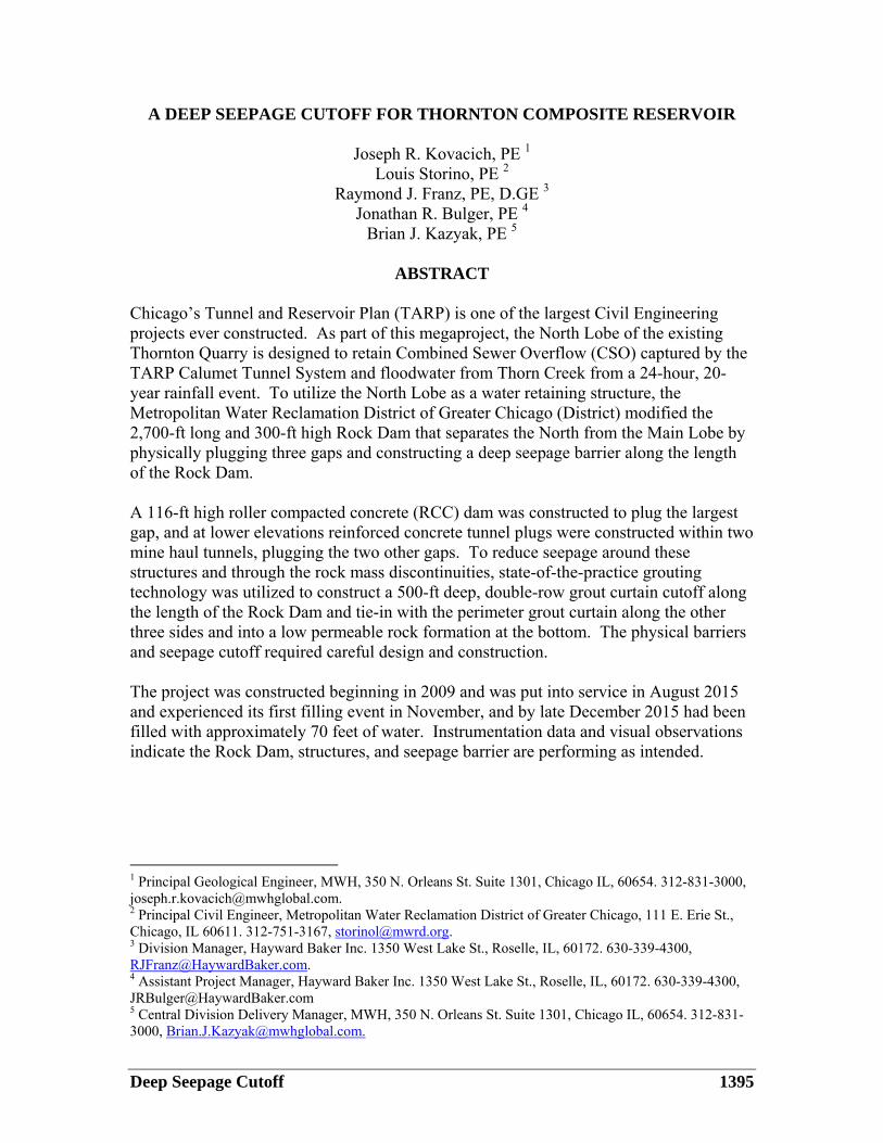
ABSTRACT Chicago’s Tunnel and Reservoir Plan (TARP) is one of the largest Civil Engineering projects ever constructed. As part of this megaproject, the North Lobe of the existing Thornton Quarry is designed to retain Combined Sewer Overflow (CSO) captured by the TARP Calumet Tunnel System and floodwater from Thorn Creek from a 24-hour, 20-year rainfall event. To utilize the North Lobe as a water retaining structure, the Metropolitan Water Reclamation District of Greater Chicago (District) modified the 2,700-ft long and 300-ft high Rock Dam that separates the North from the Main Lobe by physically plugging three gaps and constructing a deep seepage barrier along the length of the Rock Dam. A 116-ft high roller compacted concrete (RCC) dam was constructed to plug the largest gap, and at lower elevations reinforced concrete tunnel plugs were constructed within two mine haul tunnels, plugging the two other gaps. To reduce seepage around these structures and through the rock mass discontinuities, state-of-the-practice grouting technology was utilized to construct a 500-ft deep, double-row grout curtain cutoff along the length of the Rock Dam and tie-in with the perimeter grout curtain along the other three sides and into a low permeable rock formation at the bottom. The physical barriers and seepage cutoff required careful design and construction. The project was constructed beginning in 2009 and was put into service in August 2015 and experienced its first filling event in November, and by late December 2015 had been filled with approximately 70 feet of water. Instrumentation data and visual observations indicate the Rock Dam, structures, and seepage barrier are performing as intended.
1 Principal Geological Engineer, MWH, 350 N. Orleans St. Suite 1301, Chicago IL, 60654. 312-831-3000, [email protected]. 2 Principal Civil Engineer, Metropolitan Water Reclamation District of Greater Chicago, 111 E. Erie St., Chicago, IL 60611. 312-751-3167, [email protected]. 3 Division Manager, Hayward Baker Inc. 1350 West Lake St., Roselle, IL, 60172. 630-339-4300, [email protected]. 4 Assistant Project Manager, Hayward Baker Inc. 1350 West Lake St., Roselle, IL, 60172. 630-339-4300, [email protected] 5 Central Division Delivery Manager, MWH, 350 N. Orleans St. Suite 1301, Chicago IL, 60654. 312-831-3000, [email protected].
1396 USSD 2016 Annual Conference
INTRODUCTION In 1972, the District’s Board of Commissioners adopted the Tunnel and Reservoir Plan (TARP) as a comprehensive pollution and flood control program for its 375 square mile combined sewer area, comprised of Chicago and 51 neighboring communities. The Deep Tunnel System (TARP Phase I) consists of 109 miles of large diameter, rock tunnels providing 2.3 billion gallons of CSO storage. Completed in 2006, these tunnels transport CSO to the three planned reservoirs around the Chicago metropolitan area. Construction of the reservoirs comprises TARP Phase II and when fully implemented will greatly increase the storage capacity of the system to approximately 18.25 billion gallons. One of the three reservoirs, the Thornton Composite Reservoir (TCR) is in service and can store nearly 8 billion gallons of CSO. The TCR is constructed in the North Lobe portion of the existing Thornton Quarry located in Thornton, IL, and is north of the I-80/294 Tollway as shown on Figure 1. The relative size and storage capacity of the TCR is shown on Figure 2. To facilitate quarrying between the Main lobe and North lobe of the Thornton Quarry without interrupting the I-80/294 Tollway, the quarry operator excavated penetrations underneath the Tollway and through the rock rib that separates the two lobes. The main penetration measures a maximum of about 200 feet wide and 116 feet high. As quarrying progressed to deeper levels, two tunnel penetrations measuring 25-ft-high and 35-ft wide and about 450- and 600-ft long were excavated. These penetrations were used by mining equipment and haul trucks to excavate and transport quarry rock from the North Lobe to the Main Lobe crusher. To make the North Lobe suitable to retain CSO, the rock rib, herein referred to as the Rock Dam, was modified by physically plugging the three penetrations to isolate the North Lobe from the Main Lobe. The largest penetration excavated under the I-80/294 Tollway Bridge, was plugged with a Roller Compacted Concrete (RCC) gravity dam, called the Gap Dam. The tunnels were plugged with reinforced concrete tunnel plugs each consisting of lining and bulkhead sections. Seepage through open fractures in the Gap Dam foundation; in the rock surrounding the tunnel plugs; and through open joints and bedding planes within the Rock Dam is controlled by a continuous grout curtain constructed along the length of the Rock Dam. The 2,700-ft long seepage barrier is tied-in with the grout curtains on the east and west sides of the North Lobe and into the underlying low permeable shale layer. The intent of the grouting along the Rock Dam is to:
1. Seal interfaces between concrete and bedrock, 2. Seal and treat faults, open joints, bedding planes, and fracture zones within the
rock mass, and thereby 3. Decrease the permeability of the dolomitic limestone to depths of as much as 500
feet to control seepage from the TCR into the Main Lobe.

Deep Seepage Cutoff 1397
North LobeThornton Comp. Res.
Main LobeActive Quarrying
I-80/294 Tollway
Scale
1000 ft
Figure 1. Aerial view of Thornton Quarry and Interstate 80/294 Tollway

1398 USSD 2016 Annual Conference
Thornton Comp. Res.Volume = 8 Billion Gal.
Chicago’sWillis TowerHeight = 1450 ft
Figure 2. Relative Size and Storage Capacity of TCR

Deep Seepage Cutoff 1399
ROCK DAM GEOLOGY Rock Dam Configuration As shown on Figure 1, the Rock Dam is oriented in the east-west direction. The crest is approximately 330 feet wide at El. 0 ft of the City of Chicago Datum (feet, CCD) and the I-80/294 Tollway is founded on an earth embankment at approximately El. +27, as shown on Figure 3. The north face of the Rock Dam extends from El. 0 to approximately El. -297.5. At the top of the Rock Dam (El. 0), there is a 50-foot-wide bench between the toe of the Tollway embankment and the uppermost quarry wall. Below El. 0 there are two intermediate benches: the Level 1 bench at approximately El. -109 and the Level 2 bench at approximately El. -180, each approximately 100 feet wide.
The south face of the Rock Dam currently extends from El. 0 to approximately El. -110 (east of the Tollway gap) and El. -297 (west of the Tollway gap). After construction of the TCR, quarrying in the Main Lobe will continue and ultimately extend the south face of the Rock Dam to a final elevation of approximately El. -450. The final configuration of the south face will include three benches, each approximately 30 feet wide, located at the Level 1 elevation (El. -109), the Level 2 elevation (El. -180) and the Level 3 elevation (El. -297). The two haul tunnels extend through the Rock Dam at Level 2 and Level 3, El. -180 and El. -297, respectively.
The Thorn Creek Diversion Tunnel extends the entire length of the Rock Dam. It is unlined, 22-foot-diameter, and a circular cross-section and is currently used to convey flood water from Thorn Creek (east of the TCR) to the Thornton Transitional Reservoir located in the West Lobe of the Thornton quarry (located west of the Main Lobe in Figure 1 but not shown). The diversion tunnel is parallel to the long axis (i.e., the centerline) of the Rock Dam and is approximately 35 feet south of centerline with its invert between El. -245 and El. -250. The tunnel is perpendicular to the Level 2 and Level 3 haul tunnels and crosses below the Level 2 tunnel by approximately 40 feet and above the Level 3 tunnel by approximately 30 feet. The Thorn Creek tunnel will eventually be plugged at both ends of the Rock Dam and will serve as an internal drainage gallery to collect groundwater and CSO seepage through the Rock Dam, and be pumped back into the TCR.

1400 USSD 2016 Annual Conference
MAIN LOBEACTIVE QUARRY
NORTH LOBE TCRLEVEL 1EL. -109
LEVEL 2EL. -180
LEVEL 3FLOOR
EL. -297.5 LEVEL 3 HAUL TUNNEL
LEVEL 3TUNNEL PLUG
B-LINE
A-LINE
THORN CREEKDIV. TUNNEL
RACINE
JOLIET ROMEO
JOLIET MARKGRAF
KANKAKEE
ELWOOD
WILHELMI
FORT ATKINSON
SCALES
EL. -500
INSTRUMENTATION
I-80/294 TOLLWAY, EL. +27
ACCESS ROAD
APPROX. FINAL PROFILE
FINAL FLOOREL. -450
EL. -298
EL. -315
EL. -348
EL. -378
EL. -427
EL. -485
ELEV
ATIO
N IN
FEE
T (C
CD)
ROCK DAM
T/ ROCK DAMEL. 0NORMAL MAX.
EL. -5
Figure 3. Typical Rock Dam Section (view to east) Lithology Geotechnical investigations and mapping of the project area indicated the Rock Dam is composed predominantly of the following sedimentary rock units:
• Silurian dolomitic limestone comprised of the Racine, Joliet, Kankakee, and Elwood formations extending from El. 0 to El. -427. The rock is fine to medium-grained dolomitic limestone; relatively pure to slightly argillaceous with occasional shale layers; dense to slightly porous; massive; occasional chert beds and nodules and irregularly-shaped vugs. Based on packer testing the dolomitic limestone units have a hydraulic conductivity of about 6 x 10⁻⁵ cm/s.
• Ordovician dolomitic siltstone of the Wilhelmi and Ft. Atkinson formations extending from El. -427 to El. -485. The rock is interbedded dolomitic limestone, silty claystone and shale; poorly indurated and susceptible to slaking and deterioration. Based on packer testing the dolomitic siltstones have a hydraulic conductivity of about 4 x 10⁻⁵ cm/s.
• Shale of the Scales formation extends from El. -485 to below El. -600. The rock is laminated, dolomitic shale, very uniform, susceptible to slaking and deterioration. This unit, which has a hydraulic conductivity on the order of 2 x 10⁻⁷ cm/s acts as an aquitard underlying the TCR that will restrict downward seepage.

Deep Seepage Cutoff 1401
Upon inspection of the lithology, it was determined that potential seepage could best be controlled by extending the continuous perimeter curtain to El. -500 and tying it into the underlying low permeable Scales formation beneath the reservoir.
The bedrock exposed in the wall s of t he Rock Dam between El. 0 to El. - 297 is predominantly dolomitic lim estone of the Racine Formation. The Racine Formation is subdivided into three sub-units, or “facies”: the Reef, Reef-Flank, and Inter-Reef facies. Of these facies, only Reef-Flank and Inter-Reef facies are exposed in the Rock Dam. Above the Level 2 bench, much of the Rock Dam is within the Reef-Flank facies.
The Reef-Flank Facies is a transitional zone between the Reef and Inter-Reef facies and is typically comprised of relative pure to slightly argillace ous dolomitic li mestone with moderately dipping beds, generally dipping between 5° and 15° to the nort h and northeast. The Inter-Reef facies consists of argillaceous dolomite with nearly horizontal bedding, often containing thin beds and nodul es of chert a nd sporadic thin partings a nd lenses of gree n shale. Bot h the Reef- Flank and Inter-Reef faci es include some relatively thin shale and siltstone layers.
Bedding planes and two prominent, nearly orthogonal sets of discontinuities (joints, faults, and shears) are prevalent throughout the Ro ck Dam at varyi ng spacings, creating a well -interlocked rock mass consisting of hard, strong, prism atic blocks. Typical orientations of these features are:
• Bedding: Reef-Flank dip 5° to 15° north-northeast direction (above El. -180); Inter-Reef dip 0°to 5° north-northeast direction (below El. -180).
• Joint Set A: Near vertical, dip 80° to 90°, dip direction N40°-45°W and S40°-45°E (includes faults and shears).
• Joint Set B: Near vertical, dip 80° to 90°, dip direction N55°-60°W and S55°-60°E.
DESIGN AND CONSTRUCTION OF THE CONCRETE STRUCTURES
To utilize the North Lobe as a water retaining structure, the Rock Dam was modified by plugging three gaps and constructing a deep continuous seepage barrier. The barrier ties into the three structures as well as the grout curtain on the east and west sides of the North Lobe. Roller Compacted Concrete Dam (Gap Dam)
Dam Design. The stability of the Gap Dam was evaluated in accordance with procedures and criteria contained in US Army Corps of Engineers Engineering Manuals following EM 1110-2-2200, Gravity Dam Design and EM 1110-2-2100, Stability Analysis of Concrete Structures. Static and pseudo-static analyses were performed for several loading cases using two-dimensional (2D) conventional methods to determine stresses on the dam and foundation as well as the sliding stability factors of safety. For determining

1402 USSD 2016 Annual Conference
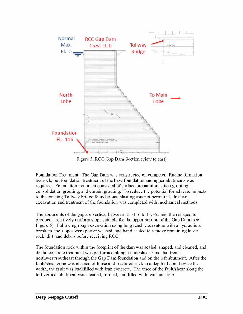
appropriate factors of safety, the Gap Dam was considered in the Ordinary Site Information category. Assuming that failure of the dam would damage the I-80/294 Tollway bridge piers, the Gap Dam is classified as a Critical Structure. The Gap Dam closes the gap between the North and Main Lobes at bench Level 1 (El. -109). The dam is founded on dolomitic bedrock of the Racine formation at about El. -116 and has a roughly trapezoidal shape with a width of approximately 60 feet at the bottom and approximately 210 feet at the top (El. 0). The I-80/294 Tollway spans the gap with a twin span, 367-foot-long bridge (only piers shown) downstream of the Gap Dam crest. Figure 4 and Figure 5 illustrate the configuration of the Gap Dam. The dam is a gravity structure, the arch shape is intended to facilitate construction and tie-in with the abutments.
Figure 4. RCC Gap Dam Plan
Deep Seepage Cutoff 1403
Figure 5. RCC Gap Dam Section (view to east)
Foundation Treatment. The Gap Dam was constructed on competent Racine formation bedrock, but foundation treatment of the base foundation and upper abutments was required. Foundation treatment consisted of surface preparation, stitch grouting, consolidation grouting, and curtain grouting. To reduce the potential for adverse impacts to the existing Tollway bridge foundations, blasting was not permitted. Instead, excavation and treatment of the foundation was completed with mechanical methods. The abutments of the gap are vertical between El. -116 to El. -55 and then shaped to produce a relatively uniform slope suitable for the upper portion of the Gap Dam (see Figure 6). Following rough excavation using long reach excavators with a hydraulic a breakers, the slopes were power washed, and hand-scaled to remove remaining loose rock, dirt, and debris before receiving RCC. The foundation rock within the footprint of the dam was scaled, shaped, and cleaned, and dental concrete treatment was performed along a fault/shear zone that trends northwest/southeast through the Gap Dam foundation and on the left abutment. After the fault/shear zone was cleaned of loose and fractured rock to a depth of about twice the width, the fault was backfilled with lean concrete. The trace of the fault/shear along the left vertical abutment was cleaned, formed, and filled with lean concrete.

1404 USSD 2016 Annual Conference
Stitch grouting was performed along the fault/shear zone to reduce the potential for seepage along this discrete feature. The stitching extended 10 feet upstream to 10 feet downstream of the grout curtains within the Gap Dam foundation. Drilling was performed using an air-track percussion drill with a 2.5-inch diameter drill bit. Holes were inclined approximately 30 degrees from vertical to intercept the fault/shear zone at depths between 5 and 10 feet below the foundation surface. After drilling, the stitch holes were washed with pressurized water and grouted using the iGrout™ system (described below). After completing the foundation treatment, a 2- to 3-ft thick unreinforced concrete leveling slab was placed to El. -114, with waterstops and contraction joints, to level the footprint of the Gap Dam. Curtain grouting was then performed from the leveling slab and consisted of a double-row curtain. Grouting along the A-line included 14 holes (seven vertical and seven inclined at 15 deg.) with vertical initial primary holes extending to El. -500 (i.e. into the Scales formation) and intended to work around turning points in the curtain, with the remaining holes extending to as much as El. -350. The B-Line was similarly completed with 14 holes. After closure was achieved, verification holes were performed along the centerline, in which packer testing indicated higher takes along finer cracks, which was likely resulted from quarry blasting damage and subsequent weathering and loosening of the upper part of the foundation. These findings necessitated a third row be constructed to a maximum depth of about El. -180. Ultimately, closure was achieved, geotechnical instrumentation was embedded in the foundation, and the RCC placement commenced.
RCC Construction Methodology. RCC mixing, placement and compaction followed the general guidelines and recommendations in American Concrete Institute ACI 207.5R. A construction staging area located just to the south of the Gap Dam was used to store aggregates, cement, fly ash, and admixtures, mixing equipment and the RCC conveyance system. The delivery of the RCC mix from the batching plant to the dam was completed using belt conveyors. In general, the RCC was placed in a serpentine pattern, starting in one corner of the dam and then placing material in multiple lanes parallel to the dam axis. The material was placed in approximately 12-inch thick lifts, and compacted using vibratory rollers to achieve the required density. To complete the dam as shown on Figure 7, 168 lifts comprising of 34,500 cubic yards of RCC were placed over the course of 134 working days.
To mitigate cracking, the Gap Dam was constructed with vertical transverse contraction joints. The five contraction joints were spaced approximately 40 feet apart and oriented radially and perpendicular to the upstream face. The joints extend in the upstream/downstream direction across the entire cross section and for the full height of the dam. The joints were formed by inserting a plate into the un-compacted RCC with a vibrating plate mounted on a backhoe. Plastic sheeting placed around the vertical plates was left in place as a bond breaker. Two vertical waterstops were installed at the upstream face for each contraction joint to cut off leakage through the joint. The bottom of the waterstops were embedded two feet into rock by coring the rock and then grouting the waterstops into place, and they extend to within one foot of the dam crest.

Deep Seepage Cutoff 1405
A facing system for both the upstream and downstream faces of the Gap Dam consisting of grout-enriched vibratable RCC (GEVR) was used to reduce seepage through the dam and to provide a surface more durable against freeze-thaw cycles and more resistant to the potential aggressive action of the CSO.
Figure 6. Aerial view of Gap Dam Foundation and Abutment Preparation
(view toward the south-southwest)
1406 USSD 2016 Annual Conference
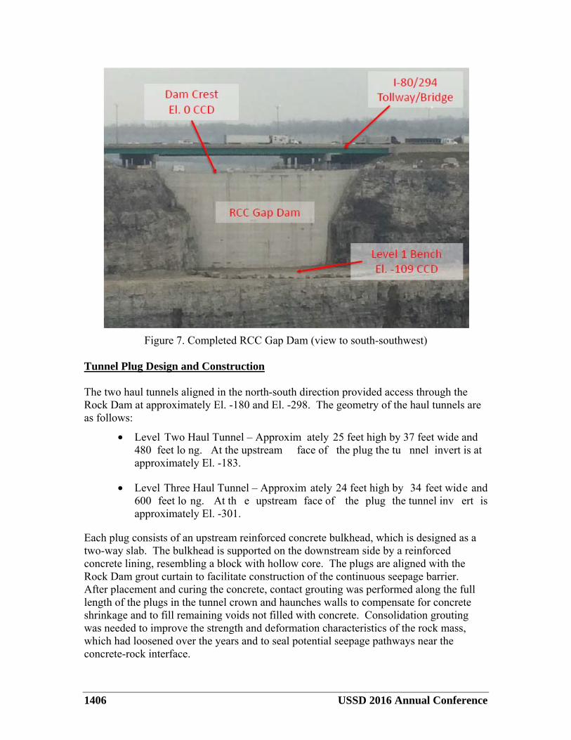
Figure 7. Completed RCC Gap Dam (view to south-southwest)
Tunnel Plug Design and Construction The two haul tunnels aligned in the north-south direction provided access through the Rock Dam at approximately El. -180 and El. -298. The geometry of the haul tunnels are as follows:
• Level Two Haul Tunnel – Approxim ately 25 feet high by 37 feet wide and 480 feet lo ng. At the upstream face of the plug the tu nnel invert is at approximately El. -183.
• Level Three Haul Tunnel – Approxim ately 24 feet high by 34 feet wide and 600 feet lo ng. At th e upstream face of the plug the tunnel inv ert is approximately El. -301.
Each plug consists of an upstream reinforced concrete bulkhead, which is designed as a two-way slab. The bulkhead is supported on the downstream side by a reinforced concrete lining, resembling a block with hollow core. The plugs are aligned with the Rock Dam grout curtain to facilitate construction of the continuous seepage barrier. After placement and curing the concrete, contact grouting was performed along the full length of the plugs in the tunnel crown and haunches walls to compensate for concrete shrinkage and to fill remaining voids not filled with concrete. Consolidation grouting was needed to improve the strength and deformation characteristics of the rock mass, which had loosened over the years and to seal potential seepage pathways near the concrete-rock interface.
Deep Seepage Cutoff 1407
In general, the construction of the plugs started with excavation of the crushed road base material and existing leveling concrete at the invert of the haul tunnels and foundation cleaning. The plug lining sections were placed in three lifts followed by the placement of the bulkheads, which were also placed in three lifts. Consolidation and contact grouting of the lining and bulkhead were completed after the lining and bulkhead had been placed and allowed to cure for a minimum of 30 days.
GROUT CURTAIN CONSTRUCTION As a chief defense against seepage of CSO from the TCR, an approximately 9,800 LF continuous double-row grout curtain was constructed around the perimeter of the Thornton Reservoir, using state-of-the-practice drilling and grouting techniques and equipment. A particular challenge to this project involved the design and construction of the seepage barrier on the Rock Dam given that it was integrated with other structures. The construction of the south seepage barrier consisted of three parts:
1. Gap Dam foundation grouting from the leveling slab at El. -114, 2. Surface grout curtain installation from the top of the Rock Dam at approximate
El. 0, and 3. Ring grouting (consolidation and contact grouting) from within the two Haul
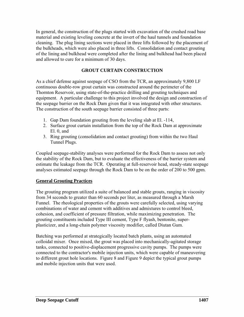
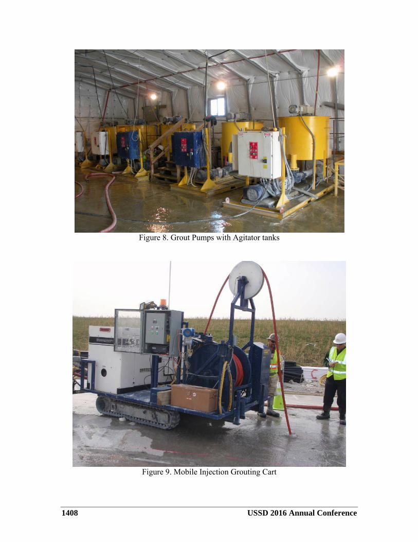
Tunnel Plugs. Coupled seepage-stability analyses were performed for the Rock Dam to assess not only the stability of the Rock Dam, but to evaluate the effectiveness of the barrier system and estimate the leakage from the TCR. Operating at full-reservoir head, steady-state seepage analyses estimated seepage through the Rock Dam to be on the order of 200 to 500 gpm. General Grouting Practices The grouting program utilized a suite of balanced and stable grouts, ranging in viscosity from 34 seconds to greater than 60 seconds per liter, as measured through a Marsh Funnel. The rheological properties of the grouts were carefully selected, using varying combinations of water and cement with additives and admixtures to control bleed, cohesion, and coefficient of pressure filtration, while maximizing penetration. The grouting constituents included Type III cement, Type F flyash, bentonite, super-plasticizer, and a long-chain polymer viscosity modifier, called Diutan Gum. Batching was performed at strategically located batch plants, using an automated colloidal mixer. Once mixed, the grout was placed into mechanically-agitated storage tanks, connected to positive-displacement progressive cavity pumps. The pumps were connected to the contractor's mobile injection units, which were capable of maneuvering to different grout hole locations. Figure 8 and Figure 9 depict the typical grout pumps and mobile injection units that were used.
1408 USSD 2016 Annual Conference
Figure 8. Grout Pumps with Agitator tanks
Figure 9. Mobile Injection Grouting Cart

Deep Seepage Cutoff 1409
All grouting was performed utilizing iGrout™, the contractor’s proprietary, state-of-the-practice, automated grouting control and data acquisition system. iGrout™ allowed simultaneous real-time control and monitoring for multiple grouting and water testing operations, an example of which is shown on Figure 10. Each of the contractor’s mobile injection units were specially designed to communicate wirelessly with the iGrout™ system. The system was also web-based so the contractor, engineer, and owner could all monitor activities in real-time and communicate enabling field staff and expedite decision making. The system operator regulated the pump speed to reach the design injection pressure, until the refusal criterion was achieved. Refusal was generally defined as 0.1 GPM, yielding an apparent Lugeon value less than or equal to the project closure criterion of 1 Lugeon (approximately equal to 1.3x10⁻⁵ cm/s), for a minimum of 5 minutes, at the maximum grout injection pressure. Holes that exceeded the closure criterion of 3.75 gal/ft of grout hole required subsequent split-spaced grout holes on either side of the precedent hole.
Figure 10. Computer Display for iGrout™ Data Acquisition and Control

1410 USSD 2016 Annual Conference
In general, grouting was performed utilizing upstage grouting techniques. Upstage grouting is the method of grouting a hole where the packer is set in a fully-drilled hole at successively shallower depths. However, where drilling circulation was lost or holes collapsed, downstage grouting methods were used. In such cases, a packer was set above the problematic zone; the stage was grouted, and then the hole was re-drilled and grouted to the intended design depth. Gap Dam Grouting As previously described, prior to placing the RCC for the Gap Dam, a triple-row grout curtain was installed along the dam foundation to depths from El. -114 to as deep as El. -500, to seal gaps between the dam leveling slab and the existing bedrock, decrease the permeability of the dolomitic limestone below the dam, and treat a fault which cuts through the proposed dam location. Drilling was performed using a water-actuated down-the-hole hammer to drill 4-inch diameter holes. Grouting was monitored and recorded through iGrout™. Once grouting was completed below the dam, the Gap Dam itself was constructed. After completion of the dam, additional holes were installed from the crest through the abutments using the water-actuated-down-the-hole hammer advanced with a purpose-built rock drill with monitoring-while-drilling capabilities. These holes were installed at angles of 0 or 15 degree from the vertical, through the dam and into the abutments and to varying lengths to maintain continuity around several turning points, as shown on Figure 11. The intention of holes inclined through the crest was to treat the RCC-rock interface and maintain grout curtain continuity with the adjacent Rock Dam grout curtain zones.
Figure 11. Gap Dam Grouting - A-line (view looking north)
Deep Seepage Cutoff 1411
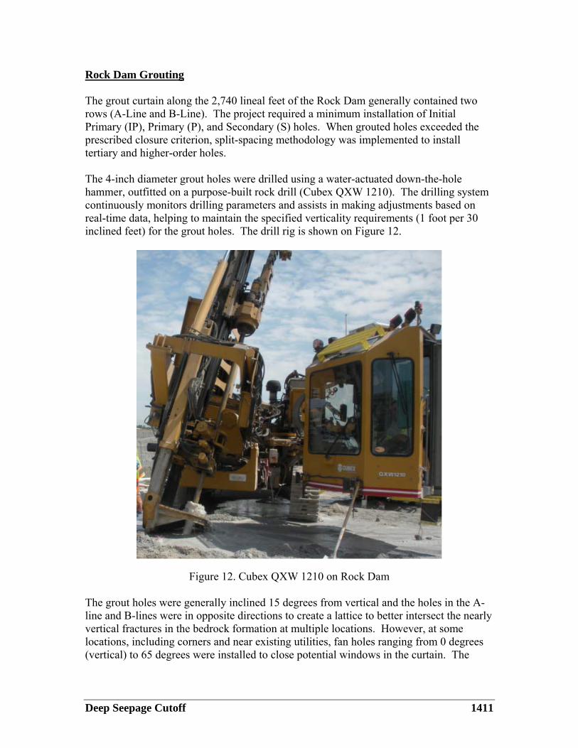
Rock Dam Grouting The grout curtain along the 2,740 lineal feet of the Rock Dam generally contained two rows (A-Line and B-Line). The project required a minimum installation of Initial Primary (IP), Primary (P), and Secondary (S) holes. When grouted holes exceeded the prescribed closure criterion, split-spacing methodology was implemented to install tertiary and higher-order holes. The 4-inch diameter grout holes were drilled using a water-actuated down-the-hole hammer, outfitted on a purpose-built rock drill (Cubex QXW 1210). The drilling system continuously monitors drilling parameters and assists in making adjustments based on real-time data, helping to maintain the specified verticality requirements (1 foot per 30 inclined feet) for the grout holes. The drill rig is shown on Figure 12.
Figure 12. Cubex QXW 1210 on Rock Dam The grout holes were generally inclined 15 degrees from vertical and the holes in the A-line and B-lines were in opposite directions to create a lattice to better intersect the nearly vertical fractures in the bedrock formation at multiple locations. However, at some locations, including corners and near existing utilities, fan holes ranging from 0 degrees (vertical) to 65 degrees were installed to close potential windows in the curtain. The
1412 USSD 2016 Annual Conference
grout holes were installed from the surface (El. 0), to elevations between El. -20 and El. -500, depending on the hole-type, and grout takes observed on adjacent holes. To monitor verticality, the contractor generally utilized a Robertson Geologging Magnetic Survey Probe. For special instances, primarily when geologic irregularities were observed during the drilling operation, the contractor utilized the Robertson Geologging Optical Televiewer. Grout holes that exceeded the verticality requirements were redrilled. In general, the Contractor met the requirements, although several holes had to be redrilled. After completion of drilling, the holes were pressure washed to clear any remaining fine drill cuttings from the hole. Depending on the order of the hole (i.e., initial primary, primary, etc.), pressure testing was performed to determine the relative permeability of the rock mass and select the appropriate starting grout mix. If high Lugeon values were observed during pressure testing, a more viscous starting grout mix was selected. Stage grouting in 20-foot increments was standard throughout the Rock Dam grout curtain installation. Grouting was most commonly performed using upstage grouting but downstage grouting was used occasionally. The grouting data were recorded in iGrout™ and then output to an AutoCAD file and to PDF reports for the Engineer’s review. Figure 13 shows a portion of the A-Line grouting progress drawings from the Rock Dam. The color-coding represents ranges of grout take for each stage. This system facilitated identification of low and high take zones, which could be targeted with higher order holes and verification holes.

Deep Seepage Cutoff 1413
ELEV
ATIO
N (F
T, C
CD)
Figure 13. Typical Rock Dam Grout Curtain Record
Verification holes were installed after completion of the A-Line and B-Line grout holes. The verification holes were cored between the A-line and B-lines using a CME 75 drill with standard wireline HQ triple-tube core barrel and tooling, having an approximate core barrel diameter of 3.75-inches. Core samples were analyzed and logged by an on-site Professional Geologist, photographed, stored in core boxes, and a verification hole summary was prepared. The verification holes were also required to be within the specified deviation requirements and have a residual hydraulic conductivity less than 1x10⁻⁵ cm/s (1 Lugeon) from water pressure testing, and not exceed the grouting closure criteria of 3.75 gal/ft. If these requirements were not satisfied, additional grout holes were installed around the verification hole until grouting closure criteria was met.
1414 USSD 2016 Annual Conference
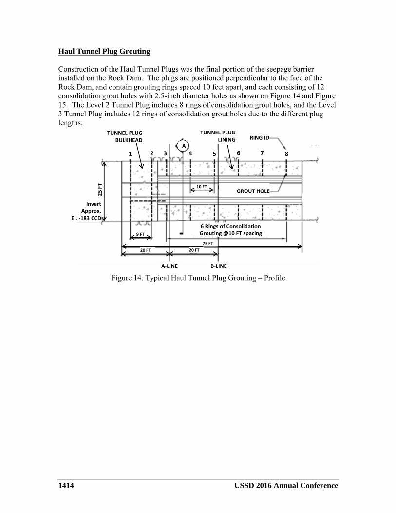
Haul Tunnel Plug Grouting Construction of the Haul Tunnel Plugs was the final portion of the seepage barrier installed on the Rock Dam. The plugs are positioned perpendicular to the face of the Rock Dam, and contain grouting rings spaced 10 feet apart, and each consisting of 12 consolidation grout holes with 2.5-inch diameter holes as shown on Figure 14 and Figure 15. The Level 2 Tunnel Plug includes 8 rings of consolidation grout holes, and the Level 3 Tunnel Plug includes 12 rings of consolidation grout holes due to the different plug lengths.
RING ID
1 2 3 4 5 6 7 8
GROUT HOLE10 FT
20 FT20 FT
9 FT
A
25 F
T
Invert Approx.
El. -183 CCD
TUNNEL PLUGLINING
6 Rings of Consolidation Grouting @10 FT spacing
TUNNEL PLUGBULKHEAD
75 FT
A-LINE B-LINE
Figure 14. Typical Haul Tunnel Plug Grouting – Profile

Deep Seepage Cutoff 1415
HOLE POSITION
300
270
240
PIPE SLEEVES TO AVOID REBAR
25 FT
330 30
60
90
120
150180
210
60° (typ)
30° (typ)Grout Hole
7 FT
7 FT (typ)
20 FT (typ)
Figure 15 - Typical Haul Tunnel Plug Grouting – Lining Section
The consolidation grout holes were designed to grout voids as well as open joints and bedding planes in the rock formation around the tunnels. Consolidation grout holes ranged in length from 25 feet to 45 feet, to provide continuous coverage and overlap 20 feet with the A- and B-line surface grout curtains. The consolidation grout holes were drilled through embedded grout sleeves using a water-actuated down-the-hole hammer outfitted on an air-track percussion drill rig, as shown on Figure 16. Each hole was pressure washed after drilling, to remove cuttings.

1416 USSD 2016 Annual Conference
Figure 16. Consolidation Grout Hole Drilling in Haul Tunnel Plug Lining Consolidation grout holes below the springline were treated using traditional upstage drilling and grouting techniques. However, to grout multiple stages at and above the springline, downstage drilling and grouting methods with mechanical packers was followed. For downstage grouting, the initial stage was drilled, and the hole was grouted with the packer positioned at the concrete-rock interface. After the grout set, the mechanical packer was removed, and the remainder of the hole drilled and grouted. iGrout™ was used throughout the grouting process to provide accurate grouting records for review and decision making. The grout takes in consolidation holes were generally low, and did not exceed the typical grout curtain closure criteria. However, because the liner was heavily reinforced on both faces, split-spacing consolidation grout holes that exceeded the closure criteria was not practical. As a result, redrilling and extending some of the consolidation grout holes and re-grouting of those holes was completed to affirm closure had been achieved. In addition to the consolidation grouting for the ring grout curtains, contact grouting was also required to fill voids between the concrete liner and the tunnel crown. Lastly, an approximately 20-foot thick reinforced concrete bulkhead was constructed at the north end of each tunnel and was grouted in a similar fashion, albeit through pre-installed holes and injection pipes.

Deep Seepage Cutoff 1417
INSTRUMENTATION AND MONITORING Survey monuments, optical survey targets, piezometers, and inclinometers are installed to monitor the performance of the Rock Dam and Gap Dam. Considering the variable frequency and height of reservoir filling, a manual system was installed to promote regular visual inspections of the facilities and instrumentation. Although an integrated automatic data collection and remote monitoring system would allow for continuous data collection and real-time monitoring, such systems can be less reliable and more prone to damage, malfunction, and neglect. An array of 59 survey monuments and targets is installed on the crest of the Rock Dam and Gap Dam and along intermediate bench faces to measure potential movement of the Rock Dam, individual benches, and “key” blocks, which are prismatic rock wedges defined by mapped rock joints. The survey monuments are installed in bedrock along the Rock Dam crest and in RCC of the Gap Dam crest and are surveyed by conventional survey methods. Because no permanent access is available to the intermediate benches, survey targets mounted on the faces of key blocks are surveyed from distance.
Twenty piezometers installed along the upstream and downstream crest of the Rock Dam measure piezometric levels in the Rock Dam and its foundation. Two rows of piezometers are installed: one row is 10 to 20 feet downstream of the grout curtain, and the second row is installed from El. 0 but on the south side of the Tollway. The piezometers are spaced approximately 300 feet apart with alternating deeper- and shallower-screened intervals with those on the south side have deeper screen piezometers. The instruments take measurements at prescribed time intervals (adjustable, but currently every 4 hours) and record the data using a self-contained programmable datalogger positioned within a weather-proof enclosure affixed to the surface casing. In addition, the piezometric levels are measured by manual water-level indicators during periodic and special dam inspections. Twelve vibrating wire piezometers are installed in the Gap Dam foundation. Piezometer cables are routed through the concrete leveling slab to the downstream side of the dam and up the back side of the dam to a centralized data logger system set on the Gap Dam crest. Sixteen inclinometers are installed along the upstream and downstream crest of the Rock Dam to monitor Rock Dam deformations and to determine whether such deformation occurs in response to operation of the reservoir or other influences (e.g. temperature). The inclinometers are in-line with the piezometers and split-spaced between them. The casings extend from approximately El. 0.0 to about El. -455, which is below the planned bottom level of the Main Lobe. The inclinometers are measured by traversing an inclinometer probe up and down the casing to measure lateral deviations of the casing.
1418 USSD 2016 Annual Conference
SUMMARY As part of the Thornton Composite Reservoir construction project, the North Lobe of the existing Thornton Quarry is designed to retain Combined Sewer Overflow captured by the TARP Calumet Tunnel System and floodwater from Thorn Creek. The Metropolitan Water Reclamation District of Greater Chicago modified the Rock Dam by plugging three gaps and constructing a deep seepage barrier along the length of the Rock Dam to create a continuous cutoff on four sides that are tied into a low permeable layer at depth. The Thornton Composite Reservoir was put into service in August 2015 and filled in November 2015. As of December 2015, the reservoir held as much as 70 feet of water. Instrumentation data and inspections performed during these early filling events indicate that the Gap Dam, Rock Dam, plugs, seepage barrier are operating as expected.