a description language and analysis tool for a software ...etd.dtu.dk/thesis/185813/imm3978.pdf ·...
TRANSCRIPT

A Description Language andAnalysis Tool for a SoftwareDevelopment Environment
Mats Anderberg
Kongens Lyngby 2005
IMM-THESIS-2005-08

Technical University of Denmark
Informatics and Mathematical Modelling
Building 321, DK-2800 Kongens Lyngby, Denmark
Phone +45 45253351, Fax +45 45882673
www.imm.dtu.dk
IMM-THESIS: ISSN 0909-3192

i
Preface
This master thesis project has been carried out in cooperation with the de-partment of Informatics and Mathematical Modeling (IMM) at the TechnicalUniversity of Denmark (DTU) in Copenhagen and Ericsson Mobile Platforms(EMP) in Lund. The project constitutes the final part of the requirements forobtaining a degree in Master of Science in Computer Systems Engineering atDTU. The work has been carried out in the period between January 11th 2005and August 19th 2005. The project was supervised by Le Chi Thu at EMP, andAssociate Professor Michael R. Hansen at the department of IMM at DTU.
Mats Anderberg, s031392Lund, August 2005

ii
Acknowledgments
First of all I would like to thank my two supervisors, Michael R. Hansen at DTUand Le Chi Thu at EMP for their guidance, support and contributions duringthe progress of this master thesis.
I would also like to thank Bo Johansson for his invaluable thoughts and endlesspatience when discussing the project with me.
The guys at the tools department at EMP for their support and comments onmy work and all other employees at EMP for always having a moment to spare.
My family for always encouraging and supporting my studies and finally mygirlfriend, Lina, for your love and for always being so considerate.

iii
Abstract
Ericsson Mobile Platforms in Lund have for configuration purposes of the theirsoftware development environment developed a small description language. Thepurpose of the language is to configure a number of tools present in the environ-ment and provide them with information making them capable of fulfilling theirtasks, which involves building software executables, configuration managementand delivery packing. The language provides the developer with a higher levelof abstraction when configuring these tools.
The language however is not supported by a formal grammar nor any capabilitiesof checking the language for errors. It is this thesis task to formally definethe syntax of the language, as much as possible compatible with the existinglanguage, and to develop a tool capable of performing error checking of thelanguage.
The outcome of this thesis is a formal grammar and semantic definition for thelanguage and a analysis tool providing syntactical and semantical checks as wellas analysis possibilities.
Keywords: BNF, EBNF, CFG, DSL, syntax tree, compiler compiler, lexicalanalysis, syntactical analysis, semantic analysis, formal grammar, visitor designpattern, software development.

iv

Contents
1 Introduction 1
1.1 Background . . . . . . . . . . . . . . . . . . . . . . . . . . . . . . 1
1.2 Problem Description . . . . . . . . . . . . . . . . . . . . . . . . . 2
1.3 Objectives . . . . . . . . . . . . . . . . . . . . . . . . . . . . . . . 2
1.4 A description language application example . . . . . . . . . . . . 3
1.5 Report Structure . . . . . . . . . . . . . . . . . . . . . . . . . . . 4
2 The EMP Software Development Environment 7
2.1 Introduction . . . . . . . . . . . . . . . . . . . . . . . . . . . . . . 7
2.2 Environment architecture . . . . . . . . . . . . . . . . . . . . . . 7
2.3 Tools . . . . . . . . . . . . . . . . . . . . . . . . . . . . . . . . . . 9
2.3.1 SDE . . . . . . . . . . . . . . . . . . . . . . . . . . . . . . 10
2.3.2 CME . . . . . . . . . . . . . . . . . . . . . . . . . . . . . . 11
2.3.3 PPZ . . . . . . . . . . . . . . . . . . . . . . . . . . . . . . 11
2.4 Summary . . . . . . . . . . . . . . . . . . . . . . . . . . . . . . . 12
3 The Current Description Language 13
3.1 Introduction . . . . . . . . . . . . . . . . . . . . . . . . . . . . . . 13
3.2 Description file types . . . . . . . . . . . . . . . . . . . . . . . . . 13
3.2.1 Product description . . . . . . . . . . . . . . . . . . . . . 15
3.2.2 Module description . . . . . . . . . . . . . . . . . . . . . . 15
3.2.3 Private description . . . . . . . . . . . . . . . . . . . . . . 15
3.2.4 Target description . . . . . . . . . . . . . . . . . . . . . . 15
3.2.5 Include description . . . . . . . . . . . . . . . . . . . . . . 15

vi CONTENTS
3.2.6 Priority between file types . . . . . . . . . . . . . . . . . . 16
3.2.7 Description file tree . . . . . . . . . . . . . . . . . . . . . 16
3.3 The language . . . . . . . . . . . . . . . . . . . . . . . . . . . . . 16
3.3.1 Variables . . . . . . . . . . . . . . . . . . . . . . . . . . . 18
3.3.2 Conditional statements . . . . . . . . . . . . . . . . . . . 22
3.3.3 Include directive . . . . . . . . . . . . . . . . . . . . . . . 23
3.3.4 Options directive . . . . . . . . . . . . . . . . . . . . . . . 24
3.3.5 Sections . . . . . . . . . . . . . . . . . . . . . . . . . . . . 24
3.3.6 Perl . . . . . . . . . . . . . . . . . . . . . . . . . . . . . . 28
3.4 Processing of description files . . . . . . . . . . . . . . . . . . . . 29
3.4.1 Multiple file processing . . . . . . . . . . . . . . . . . . . 29
3.4.2 Single file processing . . . . . . . . . . . . . . . . . . . . . 31
3.5 Fallacies and pitfalls . . . . . . . . . . . . . . . . . . . . . . . . . 32
3.5.1 Absence of formal grammar . . . . . . . . . . . . . . . . . 32
3.5.2 Handwritten parser . . . . . . . . . . . . . . . . . . . . . . 33
3.5.3 File processing . . . . . . . . . . . . . . . . . . . . . . . . 33
3.5.4 Variable handling . . . . . . . . . . . . . . . . . . . . . . . 33
3.5.5 The extensive Perl availability . . . . . . . . . . . . . . . 34
3.6 Summary . . . . . . . . . . . . . . . . . . . . . . . . . . . . . . . 34
4 The New Description Language 37
4.1 Introduction . . . . . . . . . . . . . . . . . . . . . . . . . . . . . . 37
4.2 Design decisions . . . . . . . . . . . . . . . . . . . . . . . . . . . 37
4.2.1 Formal grammar . . . . . . . . . . . . . . . . . . . . . . . 38
4.2.2 Handwritten parser . . . . . . . . . . . . . . . . . . . . . . 38
4.2.3 File processing . . . . . . . . . . . . . . . . . . . . . . . . 38
4.2.4 Perl dependencies . . . . . . . . . . . . . . . . . . . . . . 39
4.2.5 Variable handling . . . . . . . . . . . . . . . . . . . . . . . 39
4.3 Grammar . . . . . . . . . . . . . . . . . . . . . . . . . . . . . . . 41
4.3.1 Directive grammar . . . . . . . . . . . . . . . . . . . . . . 42
4.3.2 Adding a grammar for the sections . . . . . . . . . . . . . 46
4.4 Semantics . . . . . . . . . . . . . . . . . . . . . . . . . . . . . . . 47
4.4.1 Directive semantic . . . . . . . . . . . . . . . . . . . . . . 48
CONTENTS vii
4.4.2 Section semantic . . . . . . . . . . . . . . . . . . . . . . . 51
4.5 Summary . . . . . . . . . . . . . . . . . . . . . . . . . . . . . . . 53
5 The Analysis Tool 55
5.1 Introduction . . . . . . . . . . . . . . . . . . . . . . . . . . . . . . 55
5.2 Tool objectives . . . . . . . . . . . . . . . . . . . . . . . . . . . . 55
5.3 Tool architecture . . . . . . . . . . . . . . . . . . . . . . . . . . . 56
5.4 Preprocessor . . . . . . . . . . . . . . . . . . . . . . . . . . . . . 57
5.5 Front End . . . . . . . . . . . . . . . . . . . . . . . . . . . . . . . 60
5.5.1 Lexical analysis . . . . . . . . . . . . . . . . . . . . . . . . 60
5.5.2 Syntactical analysis . . . . . . . . . . . . . . . . . . . . . 64
5.5.3 Building the AST . . . . . . . . . . . . . . . . . . . . . . 68
5.6 Back End . . . . . . . . . . . . . . . . . . . . . . . . . . . . . . . 69
5.6.1 The Visitor Pattern Technique . . . . . . . . . . . . . . . 70
5.6.2 Recursive analysis . . . . . . . . . . . . . . . . . . . . . . 74
5.6.3 Semantic analysis . . . . . . . . . . . . . . . . . . . . . . . 76
5.6.4 InitVariantMatrix . . . . . . . . . . . . . . . . . . . . . . 79
5.6.5 FileAnalysisVisitor . . . . . . . . . . . . . . . . . . . . . . 80
5.6.6 VariableAnalysisVisitor . . . . . . . . . . . . . . . . . . . 81
5.6.7 BackEndManager . . . . . . . . . . . . . . . . . . . . . . . 82
5.6.8 ASTTable . . . . . . . . . . . . . . . . . . . . . . . . . . . 82
5.6.9 BackEndError . . . . . . . . . . . . . . . . . . . . . . . . 83
5.7 Summary . . . . . . . . . . . . . . . . . . . . . . . . . . . . . . . 83
6 Conclusion 85
6.1 Status . . . . . . . . . . . . . . . . . . . . . . . . . . . . . . . . . 85
6.2 CDL vs. NDL . . . . . . . . . . . . . . . . . . . . . . . . . . . . . 86
6.2.1 Syntax . . . . . . . . . . . . . . . . . . . . . . . . . . . . . 86
6.2.2 Semantic . . . . . . . . . . . . . . . . . . . . . . . . . . . 87
6.2.3 Language processing . . . . . . . . . . . . . . . . . . . . . 87
6.3 Further work . . . . . . . . . . . . . . . . . . . . . . . . . . . . . 88
6.3.1 Migration and integration . . . . . . . . . . . . . . . . . . 89
A Terminology and Abbreviations 91

viii CONTENTS
B Domain Specific Languages 93
C Compiler Theory 95
C.1 Introduction . . . . . . . . . . . . . . . . . . . . . . . . . . . . . . 95
C.2 Compiler theory . . . . . . . . . . . . . . . . . . . . . . . . . . . 95
C.3 Formalism and notation . . . . . . . . . . . . . . . . . . . . . . . 96
D JavaCC 99
D.1 Introduction . . . . . . . . . . . . . . . . . . . . . . . . . . . . . . 99
D.2 Lexical Analysis . . . . . . . . . . . . . . . . . . . . . . . . . . . 101
D.3 Syntactical Analysis . . . . . . . . . . . . . . . . . . . . . . . . . 104
D.4 AST . . . . . . . . . . . . . . . . . . . . . . . . . . . . . . . . . . 106
D.5 Summary . . . . . . . . . . . . . . . . . . . . . . . . . . . . . . . 108
E New Description Language BNF 109
F Example of generated AST 113

List of Figures
1.1 An example description file . . . . . . . . . . . . . . . . . . . . . 3
1.2 The description hierarchy pinpointed by the example . . . . . . . 4
2.1 Modules and description files . . . . . . . . . . . . . . . . . . . . 8
2.2 Example of description file hierarchy . . . . . . . . . . . . . . . . 9
2.3 Description file interaction with tools. . . . . . . . . . . . . . . . 10
2.4 Generating the make file . . . . . . . . . . . . . . . . . . . . . . . 11
3.1 Description file types . . . . . . . . . . . . . . . . . . . . . . . . . 14
3.2 Description file tree . . . . . . . . . . . . . . . . . . . . . . . . . . 17
3.3 Variables states . . . . . . . . . . . . . . . . . . . . . . . . . . . . 18
3.4 Variables states with some override aspects added . . . . . . . . 20
3.5 SDE description file processing steps . . . . . . . . . . . . . . . . 30
3.6 SDE description file processing steps . . . . . . . . . . . . . . . . 31
4.1 Example description file tree . . . . . . . . . . . . . . . . . . . . 39
4.2 Variable handling . . . . . . . . . . . . . . . . . . . . . . . . . . . 40
4.3 Example of how the variables are handled . . . . . . . . . . . . . 41
4.4 AST for an if statement. . . . . . . . . . . . . . . . . . . . . . . . 44
5.1 Phases in the analysis tool mapping to a typical compiler . . . . 57
5.2 Analysis tool architecture . . . . . . . . . . . . . . . . . . . . . . 58
5.3 The preprocessor step . . . . . . . . . . . . . . . . . . . . . . . . 58
5.4 A preprocessed file and corresponding non preprocessed file . . . 59
5.5 The solution to corrupted line number . . . . . . . . . . . . . . . 59

x LIST OF FIGURES
5.6 The approach of having two parsers . . . . . . . . . . . . . . . . 65
5.7 Block diagram depicting the back end . . . . . . . . . . . . . . . 70
5.8 Class diagram depicting the back end design . . . . . . . . . . . . 71
5.9 Vistor pattern overview . . . . . . . . . . . . . . . . . . . . . . . 72
5.10 Traversing the AST with a visitor . . . . . . . . . . . . . . . . . . 73
5.11 Building the file tree . . . . . . . . . . . . . . . . . . . . . . . . . 75
5.12 Infinite loop of inclusions . . . . . . . . . . . . . . . . . . . . . . 76
5.13 Example on how the variables are handled . . . . . . . . . . . . . 77
5.14 Variant target matrix . . . . . . . . . . . . . . . . . . . . . . . . 80
5.15 ASTTable . . . . . . . . . . . . . . . . . . . . . . . . . . . . . . . 83
C.1 Typical phases in a compiler . . . . . . . . . . . . . . . . . . . . . 96
C.2 The steps involved in constructing the AST . . . . . . . . . . . . 97
D.1 Generation of JavaCC parser . . . . . . . . . . . . . . . . . . . . 99
D.2 State machine features in lexical analyzer. . . . . . . . . . . . . . 102
D.3 The Node interface . . . . . . . . . . . . . . . . . . . . . . . . . . 107

List of Tables
3.1 Section classes . . . . . . . . . . . . . . . . . . . . . . . . . . . . 26
4.1 General non terminal symbols . . . . . . . . . . . . . . . . . . . . 42
4.2 Main differences between CDL and NDL . . . . . . . . . . . . . . 54
5.1 Predefined function library . . . . . . . . . . . . . . . . . . . . . 78
C.1 Regular expression notation . . . . . . . . . . . . . . . . . . . . . 98
D.1 Expression kinds of JavaCC tokens . . . . . . . . . . . . . . . . . 101

xii LIST OF TABLES

Chapter 1
Introduction
1.1 Background
Ericsson Mobile Platforms (EMP) develops platforms for mobile phones. Themobile platform is a complex architecture that involves several years of researchand development.
Building software for large scale software systems, such as the mobile platformsdeveloped at EMP, is a challenging task and when the number of files the soft-ware implementations reside in goes beyond several thousands it is importantthat the environment responsible for typical activities, such as building the soft-ware, configuration management and distributing the software to customers, isable to handle those in an efficient and time-saving manner.
To meet these requirements, at least to some extent, imposed on the softwaresystem, EMP has developed a small description language with the purpose ofsupporting the activities mentioned above. The language is used when settingup the build environment, meaning the software environment supporting thedevelopment of executable units, of the mobile platform software. The languageis also used by the configuration management and when delivery packing theplatform for different releases to customers. Easily put, the language describesfor different tools present in the software environment what to build, whatto version control and what to delivery pack. The purpose is to release thedeveloper from the burden of writing for example make programs, in the casebuilding the software executable, by hand. Instead the description language canbe used to simplify the software development.
In the sense of lifting the abstraction of software development for a particulardomain the description language can be considered a Domain Specific Language(DSL). A DSL is language with a small vocabulary dedicated to particular do-

2 Introduction
main or problem, which in the case of the description language is the EMPsoftware development environment. Hence the description language is not aGeneral Purpose Language (GPL) like Java or C but a highly specialized lan-guage with small array of possible applications. A small introduction of DSLsare given in appendix B.
1.2 Problem Description
The language was originally designed to be used in somewhat simpler applica-tions but as time has progressed it has evolved to be more complex and hardto maintain. Functionality has been added but not documentation or any errorchecking capabilities. The language of today is powerful (partly because it pro-vides an interface to the scripting language Perl), but unfortunately there is noformally defined syntax for the language. This means that it is hard to find e.g.errors and difficult for the developer to correctly implement descriptions in thelanguage.
Not having a strictly defined grammar nor a proper tool to syntactically and se-mantically check the language for errornous constructions causes possible faultsin the files to be detected at a very late stage in the chain of actions that leadto the building of an executable or delivery packing of a product. This is notfeasible and the purpose of this master thesis is to provide the language with aformal definition and a tool capable of performing checks to pinpoint errornousconstructions.
1.3 Objectives
The goal of this master thesis project aims at achieving three major objectives:
A Learn and briefly document the approximate syntax of the current descrip-tion language (CDL) language in a precise (informal) way. Understand thelanguage and its applications.
B Define a new description language (NDL) as much as possible compatiblewith the present language and describe it formally.
C Design and implement an prototype analysis tool capable of performingsyntactical and semantic checks and analysises based on the NDL.
The objectives of this thesis aims of supplying EMP with a grammar and atool that supports a more strict language with defined rules and constrainedbehaviour. Hence the objective is not to design a whole new concept for the

1.4 A description language application example 3
description language and its applications but to define the syntax more strictlyand to develop a tool adhering to that syntax. The major objective of the thesiscould alternatively be expressed as providing EMP with a basic foundation anda new paradigm for checking and evaluating the description files.
1.4 A description language application example
To illustrate how the description language is used, this section gives a concreteexample of an application of the language, namely the building of an executable.An example description file is depicted in figure 1.1.
!set VAR1 = module1 !set VAR2 = target2
[Modules]
!if VAR1 == module1 module1 !else module2 !endif
[Targets]
!if VAR2 == target1 target1 .\dir\target1.cfg !else target2 .\dir\target2.cfg !endif
[SourceFiles] .\dir\file1.c .\dir\file2.c .\dir\file3.c
[IncludeFiles] .\dir\file1.h .\dir\file2.h .\dir\file3.h
variable definition
sections
diretives
target inclusion
module inclusion
Figure 1.1: An example description file
The description language is made up of directives, like variable definition andconditional statements, and sections. Each section, which starts with a uniqueidentifier enclosed in square brackets (e.g. ”[Modules]” provides a particularfunctionality.
In the case of the example in figure 1.1 the file defines two variables (VAR1 andVAR2) that is later used in the conditional statements. The ”[Modules]” sectionidentifies the inclusion of other description files. The module concept will be

4 Introduction
further explained in section 2.2. The ”[Targets]” section identifies the inclusionof a description file that specifies the configuration of the target, meaning thespecial compilation settings etc. for a given target (see section 3.2 for moreinformation). A target can for example be Windows or the real processor usedin the mobile platform. The two sections in the end of the file, ”[SourceFiles]”and ”[IncludeFiles]”, lists the names of files that is a part of for example thebuilding of an executable unit.
The module and target inclusion identifies a file hierarchy of description filesthat describes for the build tool what to build and how to build the executable.The file hierarchy for the example file in figure 1.1 is given in figure 1.2.
product
module1 target2
Defines indivudal settings for a module
Defines the configuration of a target
Defines the overall composition of a product
Figure 1.2: The description hierarchy pinpointed by the example
The root description in the file hierarchy is called a product description andtypically defines the overall composition of the product (or the executable).When processing these files the build tool is able to extract the informationneeded to build the executable, which includes the files to be build and theirindividual settings as well as the configuration of the target.
This example only shows one application of the language and only gives a briefoverview of it. The purpose is the give a short introduction to the language with-out going into to much detail that will hopefully provide a basic understandingthat could be useful when reading the rest of the report.
1.5 Report Structure
The report is separated into chapters that map to the objectives described above:
• Chapter 2 describes the domain of the description language, namely theEMP software development environment.
• Chapter 3 covers objective A, including an identification of possible weak-nesses of the current language.

1.5 Report Structure 5
• Chapter 4 covers objective B, proposing a new language based on thecurrent one.
• Chapter 5 covers objective C, invoking the new language into an analysistool.
• Chapter 6 summarizes the thesis and pinpoints further work.
At the end of each section there is a summary section intended to briefly informthe reader of the key information described in the chapter.
The reader is recommended to read the report in a top down fashion sincethe sections are dependent on one another in the order they appear. Alsofundamental knowledge of language theory and compiler techniques are assumedalthough appendix C provides an brief overview on the fundamentals of compilerand language construction.

6 Introduction

Chapter 2
The EMP Software
Development Environment
2.1 Introduction
This section aims at briefly presenting the EMP software development environ-ment as seen from the description language point of view. Only the parts ofthe environment where the description language plays a vital role will be intro-duced, hence this section will not give a comprehensive and detailed descriptionof the complex structure that forms the EMP software development environ-ment. It will merely present the tools using the description files and how thesefiles interact with the environment.
The description files are in this section regarded as black boxes with informa-tion somehow needed by the software development environment, although abrief example is given in the introducton. The detailed description of whatthe description files actually contain and implement are left to chapter 3 whichwill thoroughly describe the actual language. For now it is enough to knowthat the description files holds information that the tools incorporated in theenvironment needs.
2.2 Environment architecture
The EMP software platform is structured as set of platform modules, eachdefining its own well-defined functionality of the mobile platform. Examplesof different functionality incorporated into these modules are SMS, MMS, datacommunication etc.

8 The EMP Software Development Environment
All modules present in the software development environment contain a so calleddescription file as depicted in figure 2.1. Figure 2.1 is oversimplified in the sencethat it only illustrates that each module has a description file. It doesn’t showthe internal structure of the modules nor the different software layers that existin the platform architecture. A module is basically a number of files (sourcefiles, document files, etc.) that together defines the functionality of the moduleand the description file for the module describes for the environment which filesthe module contains and how it should be configured.
Module
descr. file
Module
descr. file
Module
descr. file
Module
descr. file
Module
descr. file
Module
descr. file
Module
descr. file
Module
descr. file
Module
descr. file
...
...
...
... ... ... ...
SW Platform
Figure 2.1: Modules and description files
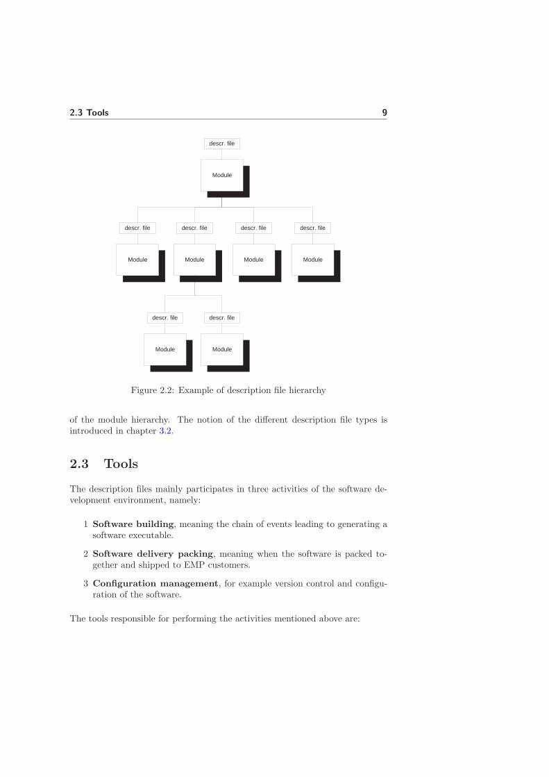
The modules together form something that can be viewed as a file hierarchywhere each module have the capability of including other modules and it is thedescription files responsibility to pinpoint how the modules are hierarchicallychained together. The root description of the file hierarchy defines which sub-sequent description files (and their modules) that forms the specific product.Figure 2.2 gives an example of how the modules and their respective descriptionfile forms a file tree.
Depending on how the different description files are included and what kind offunctionlity they implement they can be divided into different classes to distin-guish between different types of descriptions. Figure 2.2 gives an overall picture
2.3 Tools 9
Module
descr. file
Module
descr. file
Module
descr. file
Module
descr. file
Module
descr. file
Module
descr. file
Module
descr. file
Figure 2.2: Example of description file hierarchy
of the module hierarchy. The notion of the different description file types isintroduced in chapter 3.2.
2.3 Tools
The description files mainly participates in three activities of the software de-velopment environment, namely:
1 Software building, meaning the chain of events leading to generating asoftware executable.
2 Software delivery packing, meaning when the software is packed to-gether and shipped to EMP customers.
3 Configuration management, for example version control and configu-ration of the software.
The tools responsible for performing the activities mentioned above are:

10 The EMP Software Development Environment
1 SDE, Software building
2 PPZ, Software delivery packing
3 CME, Configuration management
All of these tools use the description files in one way or the other to extractinformation needed for their respective functionality. The main purpose of thedescription language is to ”configure” SDE and CME so that these can be usedin a wide array of applications without having to modify the tools. Figure 2.3helps in resolving how the various tools interact with the description files.
Figure 2.3: Description file interaction with tools.
In figure 2.3 the role of the description files in the software environment isillustrated. As can be seen, almost all interaction with the description files aredone via the intermediate usage of SDE. Therefore SDE is not only present inthe process of building the software executable but also provides an interfaceto the configuration management (CME) and the delivery packing (PPZ). Thedoted lines in figure 2.3 represents usage and the filled lines represent that somekind of output is produced. The subsequent sections will elaborate further onthe specific purpose of each tool and and how they interact with the descriptionfiles.
2.3.1 SDE
SDE handles the vital role of building executable units for the mobile platformproducts (see also section 1.4). It interfaces compilers, make programs, config-uration management systems and debuggers. The main objective for SDE is toprovide a tool for software development that can generate executable units both

2.3 Tools 11
for the different mobile platform CPUs and for simulation and debugging thesoftware on a PC. This main objective and how SDE uses the description filesfor this purpose is illustrated in Figure 2.4.
Description files SDE Make file Make Executable unit
Figure 2.4: Generating the make file
The input to SDE are description files hierarchy identifying the entire softwareplatform to SDE. SDE parses these files to extract the information needed toproduce the makefile. This basically includes extracting information regardingwhich files in the platform that should be apart of the build and detailed makerules needed by the make tool. The platform can be built for different softwaretargets and different variants of the platform. A variant is basically a subsetof the software platform that defines individual settings. Different variantstypically only differ in a few source files or settings.
2.3.2 CME
The major CM system for software development within EMP is ClearCaseTMandCME is a software plugin to that tool. CME uses SDE to get product informa-tion from the description files necessary when performing version handling ofthe platform software.
CME uses the description files to extract file information needed when per-forming a ”freeze” on a software product. A freeze is when files are versionedtogether to form a well-defined portion of software. CME can extract infor-mation from the description files on three different levels of abstraction; 1) themodules for a given product, 2) the files for a given product or, 3) the files ina given module. Hence the CME usage of the description files are not neces-sarily applied to the entire file hierarchy but can also be invoked on a singlemodule and thereby a single description file. CME usage of the description filesare always done through SDE, which provides an interface for the functionalitydesired by CME.
2.3.3 PPZ
The tool responsible for delivery packing the platform software into a zip-file isPPZ. The zip-file , that is based on the content of the description files, is thenreleased to the EMP customers. PPZ is a perl script that uses SDE to extractthe useful information from the description files.

12 The EMP Software Development Environment
PPZ takes the informations extracted from the description files, via SDE, andtransforms the original structure and contents of the description files to fit thepurposes of the customer, which is illustrated as the delivery/customer portionin figure 2.3. SDK is a tool used by the customer to extract information from thedescription files used by the customers. Therefore the SDK includes a versionof the SDE tool in addition to the transformed description files.
2.4 Summary
The description language dictates some important aspects of the software de-velopment environment for a couple of tools present in the very same. It helpsthese tools in resolving which files are a part of the software platform and howthe software should be built, delivery packed and version controlled.
The platform is composed of a number of modules that each implement a por-tion of the mobile platform functionality. Each module contain a descriptionfile, implemented in the descripition language, responsible for defining the con-tents and specific configurations for the module. Together the modules form ahierarchy where the description files act as ”glue”, linking the platform producttogether.

Chapter 3
The Current Description
Language
3.1 Introduction
This chapter describes the current description language (CDL), both in termsof the functionality provided by it and in terms of the detailed syntax and howthe files are processed. The disadvantages and possible pitfalls of the languageare also investigated and highlighted.
The chapter is organized as follows; Section 3.2 describes the different de-scription file types of the language and the detailed syntax of the languageis described in section 3.3. Section 3.4 describes how the files are parsed andprocessed as of today and section 3.5 highlights identified weaknesses of CDL.
3.2 Description file types
As mentioned in section 2.2 the platform software is made up of modules whereeach module contains a description file. Each description file adheres to one offive different types of descriptions, namely:
• Product description file, the root file of the description file hierarchy.
• Module description file, the file identifying the configuration and contentof a module.
• Target description file, the file specifying the configuration of a target.

14 The Current Description Language
• Private description file, developer unique description file capable of over-riding settings made in the modules.
• Include description file, description file that gets included via a includedirective.
The type a file is given is not a constant property of the file, but dependson the way the file is referenced in the description file tree. This is typicallyonly applied for the product and module descriptions. A file that is a productdescription in one run could very well be a module description in the next.To simplify the distinction between different types, naming conventions exists.But hypothetically a arbitrary description file can be any of the above listeddescription types, which is solely dependent on the the way it is referenced. Thenotion of description file types is depicted in figure 3.1 using a UML notation.
<<Description file>> "sub module"
<<Description file>> "module"
<<Description file>> "private"
<<Description file>> "target"
<<Description file>> "product"
Include
Sub Module <<Description file>>
"include"
<<Description file>> "any"
Figure 3.1: Description file types
As illustrated in figure 3.1 a description file can include other description files,either via the Include concept or the sub-module concept. It is important todistinguish between these two notions of inclusion. The Include concept is alogical include and the included file is a part of the file it is being included from.Typically the include file is of the type include description file but could theo-retically be any description file type. The sub-module concept is a logical partof the module which is independently version controlled. The sub-module areCM-modules of their own. The inclusion and sub-modules create a descriptionfile hierarchy which for a platform contains several hundred description files.

3.2 Description file types 15
3.2.1 Product description
This is normally the top level file for the product. The product description caneither list all the files to be used for the build by itself or it can reference other,via the Sub-module concept software modules descriptions that in turn list thefiles to be used, see for example the example in section 1.4. You could say thatthe product description defines the composition of the product.
3.2.2 Module description
This is the top level file in a CM-module. It defines the contents of the moduleand how the module participates in the building of system. A software moduledescription file typically contains the name of all the files needed to build themodule and the individual compilation settings for the files. The fact that theproduct only references the module description means that it has no knowledgeof the modules individual files. This also means that the module has full controlof which files to use and the individual settings.
3.2.3 Private description
This type of file is normally unique for each individual developer. They are usedto add new files or settings to the main configuration or to override specificationsin the main configuration. This facilitates testing without the need to check outor modify the official description files. More than one private description filecan be used for the same product.
3.2.4 Target description
This type of description file describe the specifics of a software target (compileretc.). SDE has a standard set of supported software targets and compilers. Adescription file for another new target can easily be created. A software modulecan for instance define a specific software target of its own. Within this modulethe actual executables for compilers and alike can be stored and CM controlled.Other description files in the hierarchy chain can also replace the definitions inthe target description files, completely or in part.
3.2.5 Include description
An include description is the type of description file that gets included via theinclude concept. This file typically defines settings needed by the module fromwhich it is included. The inclusion is made through the include directive whichis described in section 3.3.3.

16 The Current Description Language
3.2.6 Priority between file types
SDE defines a specific order in which the file types are prioritized. This meansthat the information in one file type can override the information stated inanother file type. The files types have the following priority:
1. Private description file
2. Product description file
3. Module description file
4. Target description file
Hence the private description has highest priority and the module descriptionlowest. A certain priority also exist within a file. The part of the file that isparsed last is the part that has highest priority. Because the files are parsedfrom top to bottom a statement in the end of a file can override a statement inthe beginning. Because the include description file is a logical part of the file itis being included from it obeys the priority rules that exist within a file.
3.2.7 Description file tree
By referencing other description files using The Sub-module inclusion conceptthe description files together form a file tree. If it exists the private descriptionsis the root of this tree and its sole leaf file is the product description. Theproduct description then references its modules and target descriptions. Targetdescriptions are typically only invoked from the product descriptions and notfrom module descriptions. The module descriptions can then invoke other mod-ule descriptions and so on. Figure 3.2 depicts and example of how a hierarchyof descriptions files can look like.
Each description file in figure 3.2 have the possibility if including additionalinclude descriptions files via the Include concept which is not shown in thefigure but should be kept in mind.
3.3 The language
The current description language does not just contain one uniform context freesyntax, but several context dependable syntaxes. CDL can be described as alanguage with three different levels or steps:
1. Directives

3.3 The language 17
Product
Private
Target Module2 Module1
Module3 Module4
Figure 3.2: Description file tree
2. Sections
3. Section languages
Step 1, Directives, can be considered as a preprocessing step of the language.This step defines a number of directives which main purpose is to define variablesand conditional statements that control the flow when the files are parsed. Thedirectives can be considered context free and are applicable in any context. Adirective is always proceeded by the ”!” character. The directives currentlydefined by the language are:
• Variable definition
• Variable deletion
• Conditional statements
• Include directive
• Options directive
Step 2, Sections, is concerned with dividing the syntax into several so calledsections. Each section defines its own syntax or language with its own specificfunctionality; step 3. Hence the languages residing in the sections are contextdependable.
The syntax of today is dictated by SDE which is responsible for parsing thedescription files. Step 1 and 2 are parsed line by line and not file by file.Hence the language can be considered as a row-oriented language and thuseach statement has to be completed in one line.

18 The Current Description Language
It’s important to distinguish between the directive part of the language on onehand and the section part on the other hand. CDL can be seen as a languagewith two phases; 1) the directives are evaluated in a preprocessing step where thevariables are given values and the conditional statements defines which rows thatare ”active”, 2) The ”active” rows in the sections are extracted and processed.Sections 3.4 describes in more detail how the language is parsed and processed.The following subsections will elaborate further on the syntax of the directivesand sections.
3.3.1 Variables
Defining a variable in the description language is accomplished with the use ofthe set directive. The syntax is as follows:
!set [Option]* Identifier [= Value]
Hence the ”!set” string identifying the kind of directive is followed by zero ormany options then a variable unique identifier to identify the variable, followedby a possible value. The value assigned to the variable could theoretically beany sequence of characters. The language of today does not support any kindof typed variables and SDE will handle all variables as strings. SDE will matchall characters, beginning with the first character after the equality sign (exclud-ing white spaces) and ending with the character proceeding the new line (alsoexcluding white spaces).
Variable states
Basically a variable in the description language can be in one of four differentstates, depicted as a state chart in figure 3.3.
1. Undefined
2. VN def, VAL undef
3. VN def, VAL def
4. Deleted
/ !set ID
/ !set ID = foo / !unset ID
/ !unset ID
Figure 3.3: Variables states

3.3 The language 19
In figure 3.3 VN represents a arbitrary variable identifier and VAL representsa possible value assigned to the variable. Figure 3.3 depicts that a variable isin one of the following states; 1) the variable is undefined, 2) the variable nameis defined but not the value, 3) the variable name is defined and so is the valueand 4) the variable is deleted. The figure implies that if a variable is in thestate adhering to number 2, it is not possible with a subsequent use of the setdirective also to assign a value to the variable. This is however not the wholetruth. SDE defines a number of options to the set directive that can be used tooverride the logic defined in figure 3.3. These options are:
• -i, irreplaceable set, i.e. from the point the variable is defined and onwardsno other definition can override this definition. However a variable that isdefined irreplaceable can be overridden if the -i option is used again.
• -f, forced set, i.e. the variable is defined and/or assigned regardless of apossible previous flag, unless it has been set as irreplaceable before.
• -l, the variable is defined locally. The variable scope is the remaining partof the file it has been defined in and in subsequently included files viathe include directive (see further section 3.3.3). At the end of the file apossible previous value for the variable is restored. If no previous value hasbeen defined the variable is deleted. The definition is ignored if a variablewith the same name previously have been defined with the -i option.
• -a, appends text to an existing variable. This option is necessary due tothe fact that a file can be parsed multiple times, and prevents the variableto contain arbitrary duplicates of the appended text.
• -e, the value is first evaluated as perl expression before assigned to thevariable.
To further illustrate how these options can be used an example is given:
!set VAR = A
!set -f VAR = B
!set -i VAR = C
!set -i VAR = D
The final value of the the variable VAR is D in the example above. The onlyway to override the initial definition (A) is to use -f or -i and the only way tooverride a variable defined with -f (B) is to use -i and finally, the only way tooverride a a variable defined with -i (C) is to use -i again (D).

20 The Current Description Language
Hence it is possible by using the right options to override the behaviour describedin figure 3.3. Figure 3.4 gives a more correct view of the states a variables canreside in. In this figure only the options -f and -i are considered. Should all theoptions be added, the state diagram would be immense and not very intuitive.
VN def, VAL undef, forced
VN def, VAL def
Undef
VN def, VAL undef, irreplaceable
VN def, VAL undef
VN def, VAL def, forced
VN def, VAL def, irreplaceable
/ forced set
/ set
/ irreplaceable set
/ irreplaceable set
/ forced set
/ set
/ forced set
/ irreplaceable set
/ irreplaceable set
/ forced set
/ irreplaceable set
/ irreplaceable set
/ irreplaceable set
/ irreplaceable set
Deleted
/ unset
/ unset
/ unset
/ unset
/ unset
/ unset
Figure 3.4: Variables states with some override aspects added
However this figure suffices to show the complex logic in defining a variable’sscope and controlling the way it can be overridden. In addition with the factthat SDE parses the description files in multiple passes (explained in sections 3.4cause implications that are obvious. These implications will not be investigatedhere, but in section 3.5, describing the fallacies and pitfalls the current languageproduce.
Variable reference
Once a variable has been defined it can be referred to in any context of thedescription file using the following construct:
!set ID = foo
%ID%

3.3 The language 21
As seen from the example above a variable reference is a variable identifier en-closed by ”%” characters (%ID%). Here %ID% will get the value ”foo”.
Variable expansion
The variable reference is expanded by SDE in the preprocessing step. SDE al-lows variables to be referred to anywhere within a description file. Theoreticallyconstructions like this are legitimate:
!set IF = if A == 1
!set SET = !set A = 2
!set ENDIF = !endif
%IF%
%SET%
%ENDIF%
Here an if statement (conditional statements will be explained in a later section)is declared as variables and then expanded to form the actual directives. Thepreprocessed file will have the following appearance:
!if A == 1
!set A = 2
!endif
This feature works fine with the way SDE is currently implemented but mayform an intolerable ambiguity when building a syntax tree, which will be inves-tigated further in chapter 4.
Multi line values
A variable defined with a value can consist of several lines (including line breaks)and can be defined using a line-oriented quoting of the value:
!set SOME_VARIABLE = << END_OF_DEF
This is one line
This is another line
END_OF_DEF
The ”END OF DEF” identifier can be an arbitrary string that is not part ofthe definition. When using the variable the full value including the line breakswill be expanded.
Variable deletion
The language also the defines the possibility to delete a previously defined vari-able. This is accomplished with the use of the unset directive which correspondsto the actions leading to the Delete state in figure 3.3 and 3.4:

22 The Current Description Language
!unset ID
This construct will cause the variable to be deleted, but also to be blocked forfurther use. Thus, a variable that has once been deleted can never be definedagain with the same variable identifier nor can it be referenced again.
Variable scope
The variable scope is per default defined to be global if the variable has notexplicitly been declared as local. A variable having been defined is applicableeverywhere in the file hierarchy. As explained earlier the language is a two phaselanguage and it is therefore legitimate to refer to a variable before it has beendefined. The preprocessing step in SDE takes care of evaluating all variablesregardless of their position in the file tree.
3.3.2 Conditional statements
The language defines the possibility to define conditional statements whichmakes it possible to control the flow of the file being ”executed”. The semanticsand the syntax resembles the one used in C source files. The following keywordsare recognized:
• !if logical-statement
• !elseif logical-statement
• !else
• !endif
• !ifdef variable identifier
• !ifndef variable identifier
The logical statements support comparison between variables and string literalsusing the operators ”==” for equality and ”!=” for not equal. The comparisonsare textual and not case sensitive. Several comparisons can be grouped togetherwith the logical operators conjunction (”&&”) and disjunction (”||”). Considerthe example:
!if A == 1 || B == 2 && C == 3
...
!elseif D != 4
...
!else
...
!endif

3.3 The language 23
Here the string preceding the equality operator is implicitly interpreted by SDEas a variable reference and the one following the operator is a value to SDE.Hence it’s legal to refer to a variable on the right side of the comparison butnot the left. Using a variable reference on the left side would make SDE firstexpand the variable and then try to look up the expanded value in the variabledatabase. The variable would not be found because it is a value and has noentry in the table and the comparison would evaluate to false which may nothave been the intension in the first place. Hence, the language contain someinconsistency in the use of variables. A string proceeding a comparison operatorin an if statement (ifdef and ifndef also for that matter) is implicitly meant asa reference but anywhere else the string has to be encapsulated between ”%”characters to take the desired effect.
As seen from the sample code above it is also possible to use the conditionalstatements elseif and else following and if statement, that resembles the mostfrequently used programming languages in their semantic and syntax to greatextent. The conditional statements are also allowed to be nested.
In conditional statements conjunction has higher precedence than disjunction.The precedence can however be overridden by grouping the logical expressionsinside parenthesis.
ifdef and ifndef
The language also defines the conditional statements ifdef and ifndef, identicalto the two directives #ifdef and #ifndef used by the C preprocessor and theirsemantic and syntax are identical:
• !ifdef variable name, the branch is taken if the variable is defined.
• !ifndef variable name, the branch is taken if the variable is not defined.
All conditional statements have to be ended with an ”!endif” to close the state-ment. This syntax is also inspired by the C preprocessor. Example:
!ifdef VAR
...
!endif
!ifndef VAR
...
!endif
3.3.3 Include directive
This directive is once again an inheritance from the C preprocessor and has thefollowing syntax:

24 The Current Description Language
!include filepath
Where filepath is a string identifying the file to be included. Files referencedwith the include statement are automatically added to the description file fromwhich they are included. The file path can either be absolute or relative to thefile containing the include statement. The file path may also contain variablereferences as parts of, or the whole file path.
3.3.4 Options directive
The options directive dictates the activation of specific flags that bear a specialmeaning to SDE when parsing a file. The syntax is as follows:
!options option
Where option is one of the following:
• Silent: Turns of various information messages that are triggered by theproduct description file.
• MultipleSections: Forces SDE to parse the entire file. The defaultbehaviour of the SDE parser is to search a file for a given section. Oncefound the parse is stopped.
• CheckDescrConditionals: Makes SDE check that if statements andclosing endif’s match.
These options all triggers the activation of a behaviour that is per default un-activated.
3.3.5 Sections
Besides the directives, that are applicable everywhere, the language defines so-called sections. Each section starts with a tag consisting of a name enclosedin square brackets which is similar to the syntax used in Windows ”ini” files.Example:
[Variants]
...
[SourceFiles]
...

3.3 The language 25
Each section provides different functionality to the environment. The number ofdifferent sections defined by the language is approximately 30 but this numberis not fixed and sections are constantly added and removed.
Additive or replacive sections
A section or more accurately the information it contains can either be replaciveor additive. In a replacive section the information can be overridden or replacedby an identical section in another file provided that the file has a higher priority.Additive means that the information is simply concatenated with other sectioninformation residing in identical sections.
Section classes
The sections can be grouped into a number of classes, each defining similar oridentical syntax and functionality. The identified sections classes are defined intable 3.1.
Besides the section classes defined in table 3.1 there are a number of miscella-neous sections which have not been able to put in specific class of sections.
File list sections
The sections adhering to this class are used to list file names in the build processfor a software product. Examples of file list sections are; ”[IncludeFiles]” and”[SourceFiles]” listing header files and compilable source files. Typically thesesections merely list the names of the files, each separated by a new line andnothing more:
[IncludeFiles]
.\dir\file1.h
.\dir\file2.h
.\dir\file3.h
But some sections also exposes the possibility of defining a number of options forthe specified file. An example of this is the ”[SourceFiles]” section that allows anumber of compilation options to be stated on the same line following the nameof the file:
[SourceFiles]
.\dir\file.c AVR(=-z9)
The compiler option is typically specified with an identifier unique for eachtarget followed by a value enclosed in parenthesis.
The file list sections are additive meaning that the contents of each section areconcatenated. However two identical file names defining different options will

26 The Current Description Language
• File list sections: These sections list files. In addition to the files listeda number of options can be stated (although only for a small number ofthe file list sections). The options might include different compiler optionsthat is to be mapped to the specified file.
• File list modification sections: Each file list section has a correspond-ing modification section with the intended functionality to remove a filelisted in the file list section.
• Packaging section These sections also lists files. The files stated in thepackaging sections are intended to be exposed to the tool responsible forpacking the platform software (PPZ) to customers.
• Packaging modification sections: Same functionality as file list mod-ification sections but for the packaging sections.
• Variant sections: The product typically produces several different ex-ecutables and the variants sections identify the names of these and howthey can be grouped together etc.
• Target specific sections: These sections identify targets specific actionsand contains all the information on how to create the makefiles for thebuild process.
• Target section: Identifies the Sub-module inclusion of target descriptionfiles.
• Module section: Identifies the Sub-module inclusion of module descrip-tion files.
Table 3.1: Section classes
result in the option to the file listed in the description file with the highest pri-ority taking precedence over the other. The typical behaviour when extractingthe files is that there are never duplicates of the same file (the key being theactual file name, excluding the path). Hence a file defined twice will result inonly one entry in the final list of files, that being the file listed in the file withthe highest priority ignoring possibly different paths.
File list modification sections
All file list sections have a corresponding modification section. These sectionare denoted with a name identical to one of the file list sections preceded witha minus:
[-SourceFiles]

3.3 The language 27
.\dir\file1.c
Each of these section can be used to remove a file that has previously been de-fined in a file list section. The removal of a files listed in these class of sectionsis done after all file list sections have been examined. The removal is also doneper section, meaning that a file listed in a ”[SourceFiles]” section can only beremoved using the ”[-SourceFiles]” section.
Packaging sections
These sections are a complementary to the previously explained file list sectionsand contain information (files) about what parts of the platform that shouldbe exposed to the EMP customers. What these sections do is to divide theplatform logically in three partitions, namely exposed files, forbidden files andother files. The exposed files are such files that always should be available toEMPs customers. The sections exposing files are named ”[Packaging Exposed*]where * is the name of one of the file list sections. Example:
[Packaging_ExposedSourceFiles]
...
[Packaging_ExposedIncludeFiles]
...
Forbidden files are the opposite of exposed, files that never should be sent to cus-tomers. These files should be listed in a section named ”[Packaging ForbiddenFiles]”.The third category, other files, consists of the files (the files listed in the file listsections subtracted by the ones listed in the packaging sections) that are neitherexposed nor forbidden. When packing the platform the platform packer decideswhich files that are to be included in addition to the exposed files with respectto the dependencies that exist between the files.
Variants sections
The product typically produces several different executables each differing ina few source files or settings. Each executable is denoted with a unique namecalled a variant. SDE defines a couple of sections that define the names of thevariants and how they can be grouped together when their individual settingsare very similar. The variant name is used throughout the description file hierar-chy to the control the ”execution” of the files with respect to the chosen variant.
Target section
The ”[Target]” section is responsible for identifying which target description fileto include. The target description file then describes the specifics for how tobuild an executable unit for that target. The syntax is typically a target uniqueidentifier followed by the path to the target description file:

28 The Current Description Language
[Targets]
IAR-ARM7 .\dir\iar-arm7.cfg
On the encounter of such a statement, provided that the target identifier matchesthe chosen target, the target description file will be included by SDE.
Target specific sections
The target specific sections are those residing in the target description file pin-pointed from the ”[Targets]” section and contains some more advanced instruc-tions. The sections defined in this type of file control the actual generation ofthe target specific makefiles. These sections are an example of replacive sectionsmeaning that can be overruled by another alike section residing in a file withhigher precedence.
Module section
The ”[Modules]” section identifies the inclusion of module description files. Amodule can be included from any type of file and the ”[Modules]” sections to-gether with the ”[Targets]” sections identifies the platform file tree when SDEparses the files. The syntax is a path pointing to the module folder in the filetree followed by a label. SDE will search the module folder for its descriptionfile. A label (CNH160676 R3E) is string identifying what version of the modulethat should be included:
LD_FuncBlocks_011\cnh160676_level0 CNH160676_R3E
There also a ”[-Modules]” section in case it is desired to remove a whole module.The syntax is identical to ”[Modules]” except the label preceding the path.
Miscallenous sections
The sections and sections classes listed above are not a complete descriptionof the various sections that are possible to use. They are however the mostimportant ones and the reader will not be exhausted with extensive knowledgeof every single existing section.
3.3.6 Perl
The description language is highly incorporated with the scripting language Perl.This due to the fact that the SDE parser is implemented in that very language.The description language itself also offers the writer to express arbitrary perlstatements, although constrained within a certain context (like the -e optionto the set directive). Whether or not this is a recommendable feature willsubsequent sections elaborate further on. For now it is just explain what is

3.4 Processing of description files 29
possible and what is not. As mentioned before the use of perl is allowed incertain predefined contexts of the files,
• In the set directive
• In if statements
• In certain sections
The perl expressions can be either arbitrary or following a strict syntax dictatedby a number of predefined functions that follow a strict syntax. Examples ofsuch are functions that return whether or not a variables name is defined andif a given variable contains a another explicitly given substring. The arbitraryexpressions, that can be invoked by using the ”-e” option to the set directive,will force SDE to interpret the assigned value as a perl expression and evaluateit as such. The arbitrary perl expressions can also be used in if statements. SDEautomatically evaluate the expressions as perl and no options has to explicitlybe stated.
The typical usage of perl is in the context of if or set directives. But SDE alsodefines sections that contain entire perl sub routines.
3.4 Processing of description files
SDE is the tool responsible for parsing and processing the description files inorder to obtain information and to produce the output needed to perform thetasks imposed on SDE by the environment. This includes providing CME andPPZ with information enabling them to fulfill their task, namely configurationmanagement and delivery packing, and building software executables.
The SDE processing of a file hierarchy of description files is not performed in onesingle parse. Instead the file system is parsed in multiple passes and eventuallyall information needed have been retrieved to form a complete information baseof the system. Figure 3.5 gives an overview of how SDE processes the descriptionfiles.
3.4.1 Multiple file processing
A ”start” description file is provided to SDE identifying the root of the filetree to be parsed (this is the typical behaviour, the objective could also be toonly process a single file). This file is typically the product description. SDEperforms an initial ”dummy parsing” of the entire file tree pinpointed by theroot description file. The dummy parsing’s main objective is to extract variableinformation and to build up a variable database for the file tree. The dummy

30 The Current Description Language
file array
Product
Private
Target Module Module
Module Module
Module Module Module Module Product Private Target
Variable DB
"Section parsing"
"dummy parsing"
n times generate use
priority
read/write read/write
high low
Figure 3.5: SDE description file processing steps
parsing also creates an array of all file paths to the included files from the rootfile. Hence the structure is no longer a tree but a flat structure organized in sucha way that the priority order explained in section 3.2.6 is fulfilled. The array isorganized in descending priority order, the file with the highest priority is locatedfirst in the array and the file with the lowest priority is located last. By retrievingthe files from the array in the order they are arranged the priority order betweenthe file types is ensured. This also implies that a priority order exists within afile type which will be based on their individual location in the file tree and inthe order in which they are defined. As mentioned in section 3.3.5 sections canbe either replacive or additive. By accessing the array either backwards or fromthe front the information in sections can be ensured to be replaced or addedwith respect to the file priorities.
The objective of the ”dummy parsing” is to ensure that all variables are defined.This is because a parent file might have variable dependencies to variables de-fined in a leaf file. Once the ”dummy parsing” is completed the following parseswill use the created file array and variable database. These parses are illus-trated in figure 3.5 as the section parsing. The section parsing will continuouslyupdate the variable database given the rules explained in section 3.3.1 adheringto the variable definition and deletion. The objective of the section parsing isto extract information from the sections needed by the activity accessing thedescription file, where activity is implied to be either, build, packaging or CMspecific actions. Each scan of the files will search for different sections and re-trieve section specific data. SDE has a number of data structures that saves the

3.4 Processing of description files 31
information extracted from the sections. Once the processing of the descrip-tion file system is ended these data structures holds the information base of theproduct (which can also be for a single file).
Because the files are parsed first one initial time and then several subsequenttimes the variable scope will be global, unless the variable is explicitly definedto be local. A variable defined further down the file tree is accessible in parentfiles in the next scan of the file array. This feature is a bit unorthodox butprobably not unintended. For example the product description may want toinclude a file depending on a specific kind of target, which is not known untillater in the processing. The inclusion is dependent on a target specific variabledefined after the product description have been parsed. But considering thecomplex way the variables can be overridden and the global variables scopein addition to the multiple parsing gives a very unintuitive variable handlingand it’s difficult to predict a variable’s value at a given time. The question iswhether the possibilities provided by the current implementation overshadowits disadvantages.
3.4.2 Single file processing
Each individual scan of a description file can be divided into two phases asmentioned in previous section:
• Preprocessing
• Section retreiving
As mentioned in the previous section some of the directives are very much influ-enced by the preprocessor used in the C programming language. The preprocess-ing done by SDE includes executing the directives in the language and providesthe section retrieving step with a preprocessed description file for further com-pilation. This step then parses the files again to extract desired informationfrom the sections. Figure 5.4 depicts this.
Preprocessing Description file Preprocessed description file Section retreiving
Figure 3.6: SDE description file processing steps
Preprocessing
What the preprocessor step effectively does is to parse the directive part evalu-ating every conditional statement in the file. Depending on whether or not the

32 The Current Description Language
conditionals evaluates to true or false, the branch will be included or excludedfrom the preprocessed file. The preprocessor also handles the variables definedand expands all references made to one of those. When the preprocessing isdone parsing the file the information contained in the file will be reduced andall variable references will be expanded leaving only the ”active” rows in thepreprocessed file.
Section retrieving
This step retrieves and processes information contained in the sections. Thesection or sections that is to be found is explicitly requested and differs fromscan to scan. In each scan of the file array, different sections are extracted toeventually form a complete information base of the system. The data is then ei-ther used to generate the make file, provide the platform packer with packagingspecific information or CME with file information.
3.5 Fallacies and pitfalls
The description language of today gives great flexibility when implementingdescriptions, partly because the powerful perl availability but also due to thefact that there is no strict grammar and very limited error checks. In addition tothe complex and unintuitive way the files are processed and parsed the languageof today highlights a number of fallacies that makes it feasible to elaborate ona refinement of the current language which regards the following matters:
• Absence of formal grammar
• Handwritten parser
• File processing
• Variable handling
• The extensive Perl availability
The following sections will elaborate further on each of these weaknesses andthe implications they impose.
3.5.1 Absence of formal grammar
The CDL is not formally defined and it is therefore difficult to know how tocorrectly implement descriptions in the language. Defining a formal grammarwould eliminate many of the ambiguities and risks in the current language andwould simplify error checking and handling.

3.5 Fallacies and pitfalls 33
3.5.2 Handwritten parser
The SDE parser is handwritten implemented in the Perl scripting language.Having a ad-hoc developed parser makes maintenance of the language very dif-ficult and also produces consistency problems in the sense that modifying theparser has to be done carefully to maintain a correct implementation.
It is therefore feasible to elaborate on another paradigm in how the language isprocessed and handled. Instead of implementing the parser by hand it wouldbe sufficient if the parser is generated using one of the vast amount of compilercompiler tools available.
3.5.3 File processing
As previously mentioned SDE parses an individual description file several times.After each scan the evaluated file (the preprocessed file) is simply thrown awayand no knowledge of the file is kept except the extracted information intendedfor the particular parse in addition with variable database that is continuouslyupdated. Parsing the files several times is time consuming and it would be morefeasible to parse a file one time extracting all information at the same time.
3.5.4 Variable handling
The multiple parsing of the description files and the fact the variables are keptfrom scan to scan implies that all variables are global if not explicitly statedotherwise. In addition to the overriding possibilities available basically meansthat every parse can tamper with all variables which in turn imposes a numberof possible unwanted ”features” in the variable handling. For example considera variable being defined and assigned a value:
!set A = 1
Then in a subsequent file the variable is overridden:
!set -f A = 2
When the first set statement is parsed in a subsequent scan of the file, theassignment will be ignored by SDE because it has not been defined with theproper option and the variable will hold the value ”2”. This might not be theintention when defining the variable in the first place, at least if the intention isto be able to use the variable with the original value in the file it is defined in.
A similar behaviour can be reproduced by using the unset statement. A variabledefined and then deleted will be deleted and unable for use in the next parse aswell.

34 The Current Description Language
Given the current implementation the only way to make sure that the valueyou assign to a variable is actually the value used when referring (provided thatyou refer to it before it is overridden) to it is to, without exception, define thevariable as irreplaceable (with -i).
The difficulties imposed by the variable handling is mainly the cause of multipleparsing and the dependencies between them with respect to the variables. Asdescribed above this might lead to undesired behaviour but might also be afeature that is needed given the current implementations of the description files.However having a more constrained handling of the variables that limit the risksthe current implementation produce is definitely desirable.
3.5.5 The extensive Perl availability
The Perl availability the language offers gives a powerful, but difficult to control,functionality. It is very easy to make mistakes but also increase the capabili-ties and adds a dimension to the language. However no errors or warnings willbe issued if the expressed perl statement contains any syntactical errors. Thefunctionality typically expressed in perl can be replaced by a number of prede-fined functions implemented by the language. It is therefore recommended thatthe use of arbitrary perl statements is abolished and replaced by a library ofavailable functions providing a constrained and well-defined functionality. Thiswould provide a more language independent solution instead of the very muchPerl dependent solution that exist today.
3.6 Summary
The EMP software development environment uses the CDL to extract informa-tion regarding the configuration of some of the tools present in the environment.The language can be said to be a two phase language; phase one being the di-rectives and phase two being the sections. The directives define fundamentalconstructs such as conditional statements and variables. The sections containinformation regarding for example the files a module contains and the individualsettings of a target. The directives are evaluated in preprocessing step, leavinga preprocessed file with only the sections remaining which are then extracted tofulfill the needs of the environment.
The descriptions files where the language are implemented in forms a file treethat identifies the configuration of an entire product to the environment. Thedescription files can be one of five different types; 1) private description, 2)product description, 3) target description, 4) module description, 5) includedescription. The type a file adheres is dependent on how it is referenced in thefile tree.

3.6 Summary 35
A number of fallacies has been identified in CDL; 1) the file processing is notoptimal, 2) the variable handling difficult to understand and may produce un-wanted features, 3) the extensive perl availability is hazardous and 4) having noformal grammar and a handwritten parser makes language maintenance difficultand the language difficult to understand. Chapter 4 will take these highlightedweaknesses into consideration when defining the NDL.

36 The Current Description Language

Chapter 4
The New Description
Language
4.1 Introduction
One of the objectives of this thesis project is to formally define a grammar andsemantic for a partly new description language (NDL), which however shouldbe to as much extent as possible compatible with the current one.
Considering the highlighted weaknesses of CDL this chapter defines a new lan-guage, in terms of a formal grammar and semantic. This chapter also introducespossible constraints and improvements to the given language. Although one ofthe requirements imposed on the thesis project is to as much as possible definethe new language to be backwards compatible with the existing, some aspectsof the current implementation is however considered hazardous and thereforefeasible to alter and improve.
This chapter is structured as follows; section 4.2 introduces a number of designdecisions based on the weaknesses identified in chapter 3, section 4.3 defines aformal grammar for NDL and section 4.4 the semantic. It is recommended thatappendix C.3 is read before section 4.3 because it introduces the formalism andnotation of the language definition.
4.2 Design decisions
Chapter 3 highlighted a number of fallacies in the CDL and the implicationsthey impose to the environment:

38 The New Description Language
• No formal grammar
• Handwritten parser
• File processing
• Variable handling
• Perl dependencies
In NDL these items are revoked and alternative solutions are used regardinghow the files the language reside in are treated and how the language is definedand implemented. The following sections elaborate on these solutions.
4.2.1 Formal grammar
CDL have no formally defined grammar. NDL however, will have a formalgrammar using the EBNF notation described in section C.3. This grammar ishowever not complete in the sense that a formal definition have been found forevery aspect of the language. The grammar for NDL is described in section 4.3.
4.2.2 Handwritten parser
The lexer and parser for NDL is not handwritten as opposed to the parser forCDL. Instead a compiler compiler tool (JavaCC) is used to generate the lexerand parser as well as a tree representation (AST) of the file being parsed. Inputto the parser is the formal grammar defined in sections 4.3. The detailed designof the parser is described in chapter 5.
4.2.3 File processing
The description files form a well defined file hierarchy of descriptions that iden-tifies and defines the platform product, which is depicted in figure 4.1.
The product description typically includes module and target descriptions andeach modules can invoke further modules. However this structure is not keptwhen SDE processes the file tree. Instead the tree is transformed into a flatstructure, or more accurately an array of the description files present in theproduct. This is explained in more detail in section 3.4.
However, when defining the new language the file tree structure is assumed tobe intact, meaning that the files are processed according to their location in thefile tree. Also the feature of parsing the files multiples times, done by SDE, is nolonger applicable. The new language is assumed to be parsed only one time, ormore correctly, the tool developed as a part of this project performs no multiple

4.2 Design decisions 39
Product
Private
Target Module2 Module1
Module3 Module4
Figure 4.1: Example description file tree
parsing. The tool scans the files a single time and in contrary to SDE, buildsan Abstract Syntax Tree (AST), representing the language grammar.
The file processing have no special meaning when defining the formal grammar,but will play a vital role when defining the language semantics. Given thenew way of processing the files, the new language is handled in more orthodoxmanner that resembles the way a traditional compiler works.
4.2.4 Perl dependencies
The current language gives great flexibility that is the extension of being ableto invoke Perl expressions, although not entirely context free, in the descrip-tion files. The new language will forbid the use Perl expressions motivated bythe possible dangers and unpredictable behaviour they might produce. Instead,inherited from the current language, a library of predefined functions are avail-able. These functions are implemented by the language and should not haveany dependencies to the Perl language.
The Perl abolishing is however only restricted to the if and set directives. It isstill possible to use Perl in other contexts.
4.2.5 Variable handling
As an extension of the assumptions made in section 4.2.3, keeping the file treeintact and single parsing, but also the implications imposed by the current vari-able handling described in section 3.5, a new more intuitive way of handlingthe variables is feasible to introduce. Instead of all variables being global, thevariables are given a more constrained scope adhering to where in the tree they

40 The New Description Language
are defined. A variable being defined in file A is applicable in that very file andin all leaf files to file A. A lot of variables defined in the product descriptionshould be regarded as constants by the sub-modules included from the productdescription. Also the private description typically defines variables that shouldoverride subsequently defined ones. Therefore it is feasible to regard the vari-ables as constants when they are propagated down their scope. In other words,a variable is override able in the file it is being defined in but in leaf files thevariable is regarded as constant and can not be overridden. This solution mighthowever be to general and occasions might occur where a variable should beable to override by leaf nodes. However for now, this kind of constrained andgeneral variable handling suffices. Figure 4.2 illustrates gives a general depictionon how the variables are handled.
Product
Target Module2 Module1
Module3 Module4
v pv
v pv ,v pd v pv ,v pd ,v tg
v pv
v pd
v tg v m1
v pv ,v pd ,v tg
v pv ,v pd ,v tg , v m1
v pv ,v pd ,v tg , v m1
Private
Figure 4.2: Variable handling
In figure 4.2 vpv denotes a set of variables defined in the private description,vpd variables defined in the product description, vtg variables defined in a tar-get description and finally vm variables defined in a module description. Thevariables are propagated down to their leaf files. An exception is the targetdescription, these variables are returned back to its parent, motivated by thatthe target description defines a number of variables that should also be visiblein the modules.
To further illustrate the scope a variable is given an simple example is given ifigure 4.3. Here, the variables C and D are inherited down to root file of thefigure from a the parent file (which is not visible in the figure). In the root filetwo new variables are defined (A and B). The file invokes two leaf modules and

4.3 Grammar 41
!set A = 3 !set B = 4
[Modules] module1.cfg module2.cfg
Local variables
Inherited variables
const C "3" const D "4"
A "1" B "2"
!if A == 1 ...
const A "1" const B "2" const C "3" const D "4"
!set B = 5 !set E = 5
Inherited variables
ERROR!
E "5"
Local variables
module1.cfg module2.cfg
Figure 4.3: Example of how the variables are handled
variables defined in the file (A and B) in addition to the inherited variables (Cand D) are merged together and passed to the included modules. In these filesthe variables are free to use (”!if A == 1” in the figure) but trying to overridethem is not possible and will produce an error (”!set B = 5” in the figure).Figure 4.3 shows that the inherited variables are regarded as constants and cannot be overridden and that variables are only visible in leaf files. If this semanticis violated an error is issued.
As a consequence of the above defined variable handling the options to the setdirective are obsolete and looses their meaning. Hence it is no longer possible todefine a variable as irreplaceable, forced or local (mapping to the -i, -f, -l flags),it is already implicitly defined by the variable handling semantics. Also giventhat the files are parsed a single time the append flag (-a) is also obsolete andcan be abolished as well as the perl flag (-e) since arbitrary Perl expressions isno longer applicable.
4.3 Grammar
Using the notation introduced in appendix C.3, this section will formally definea grammar for the description language. First the directive part is defined and

42 The New Description Language
then the languages residing in the sections are added. Before defining the actualgrammar, table 4.1 gives a number of general terminal symbols used universallythroughout the grammar.
Terminal Regular Expression Description
ID [A-Za-z0-9- ]+ Identifier, typically identifiesthe name to a variable
Ref ”%”Identifier”%” Variable referenceOpt ”-”[iflea]+ Option to set directiveStr [.]+ String literalQStr ”””[.]+””” Quoted string literalDrive [A-Za-z]”:\” Identifier denoting the beginning of
an absolute file pathRelPath ”.\” Identifying the beginning of a
relative file pathNL ”\r\n” — ”\r” — ”\n” New line
Table 4.1: General non terminal symbols
4.3.1 Directive grammar
Given the possible directives available in the language described in section 3 thefollowing start symbol for the language can be defined:
Stmt → (Set | Unset | If | Ifdef | Ifndef | Include | Options)*
where each nonterminal on the right hand side corresponds to a directive in thelanguage and Stmt is an arbitrary sequence (zero or many) of directives. Herefollows the production rules for each of the directives.
Set directive
The set directive can be described by the following BNF productions:
Set → ”!set” (Opt)? ID (”=” (Val | Func)+)? NL
Val → (Str | Ref)+
Func → ID ”(” Param (”,” Param())* ”)”
Param → QStr | Ref | ID | Func
Hence the value assigned to the variable, which is optional to define, can bea arbitrary sequence of strings, variable references and functions, where Funccorresponds to the predefined functions defined by the language described in

4.3 Grammar 43
section 4.2.4. A possible function application will be evaluated and its valueconcatenated with the rest of the value. In the current language the options toa set statement, here defined as the terminal Opt, have a special meaning. Inthe new language they are allowed by the grammar but simply ignored by thesemantical analysis (however resulting in a warning message) since their mean-ing is obsolete. The grammar for a function also shows that they can be nestled.
If directive
the if directive can be described by the following BNF productions.
If → ”!if” BExp NL Stmt (”!elseif” BExp NL Stmt)* (”!else” NL Stmt)? ”!endif” NL
BExp → OrExp
OrExp → AndExp (”——” AndExp)*
AndExp → (EqExp | Func) (”&&” (EqExp | Func))*
EqExp → (ID (”==” | ”!=”) Val) | ( ”(” BExp ”)” )
The recursive call to Stmt from within the if statement shows the nestling ca-pabilities of the construct. An if statement can have zero or many branchingelseif’s and an optional else before the statement is finalized with the keyword”!endif”. The rules defined for the logical expression dictates that conjunctionbinds tighter than disjunction. Defining the precedence between conjunctionand disjunction ensures an unambiguous grammar [1] as opposed to an ambigu-ous one. In an ambiguous grammar a sentence in the language can be derivedwith two different parse trees which is highly unsatisfactory. The grammar alsoallows the boolean expressions to be grouped together in parenthesis to changethe precedence of the expression. For example !if A == 1 || (B == 2 && C== 3) gets a different meaning than !if (A == 1 || B == 2) && C == 3. Therules defined above map directly to the current implementation of the languagewith the exception of not allowing arbitrary perl expressions within a booleanexpression.
Given a the above defined rule for an if statement, the following example,
!if A = 1
!set X
!elseif A = 2
!set Y
!else
!set Z
!endif

44 The New Description Language
IfStmt
Exp
EQ
Identifier value
A "1"
Elseif Else
Set
Identifier
X
Exp
EQ
Identifier value
A "2"
Identifier
X
Set
Set
Identifier
Y
Set
Identifier
Z
Figure 4.4: AST for an if statement.
would result in the AST depicted in figure 4.4. In figure 4.4 it can be seen howIfStmt has its branching elseif’s and else’s as children and they in turn definetheir respective boolean expressions and statements as their children.
Ifdef and Ifndef directive
The ifdef and ifndef directive can be described by the following BNF produc-tions:
Ifdef → ”!ifdef” ID NL Stmt (”!else NL Stmt)? ”!endif” NL
Ifndef → ”!ifndef” ID NL Stmt (”!else NL Stmt)? ”!endif” NL
The grammar for the ifdef and ifndef statements are identical, differing only inkeyword identifying the directive (”!ifdef” or ”!ifndef”). The rules depicted heremap to the current implementation of the language with the exception that SDEallows branching elseif’s, whereas the new language do not. That feature is notconsidered adding any considerable functionality to the language and thereforeremoved.
Unset directive
The unset directive can be described by the following BNF production:
Unset → ”!unset” ID NL

4.3 Grammar 45
This rule is straightforward and maps directly to the language given by SDE.
Options directive
The options directive can be described by the following BNF production:
Options → ”!options” (”-l”)? ((”CheckDescrConditionals” (”error” | ”fatal”)?)| ”MultipleSections” | ”Silent”) NL
This rule is straightforward and maps directly to the language given by SDE.
Include directive
The include directive can be described by the following BNF production:
IncludeStmt → ”!include” (”-b”)? FilePath NL
FilePath → (Ref | Drive | RelPath)? (Ref | ID)* (File)?
File → ID ”.” ID
The rule for an include statement is straightforward and maps directly to thecurrent language. Defining a grammar for file paths in the description languageis however a bit trickier. A file path can be either absolute or relative andtherefore beginning with one of the regular expressions defined by AbsPath orRelPath. This however not the whole truth. The file path can also be a variablereference, either as a part of the path or the entire file path. The file pathtypically ends with File. This is however only the case when the full file pathis written explicitly and the file path is not a directory. The FilePath grammardoes not constrain the user to only write legal file paths but does resolve someambiguities and provides the semantic analysis with a tree structure definingthe full file path.
Define macro
This is a new directive introduced in NDL. Its objective is to replace the exist-ing possibility of defining multi line values to variable and its syntax is identicalwith the exception of the new keyword ”!define”:
!define SOME_VARIABLE = << END_OF_DEF
This is one line
This is another line
END_OF_DEF
The reason for defining a new directive for multi line variables is that the valuecould be an arbitrary number of statements of the language. Because the vari-ables are expanded after the syntax tree is build (see chapter 5 for details) it

46 The New Description Language
would contain an ambiguity and the expressions has to be re parsed in orderto obtain the correct information. Therefore multi line variables are separatedfrom ”ordinary” variables by the use of this macro construct. In order to re-solve the ambiguity in the AST this construct is handled by a preprocessingstep described in more detail in chapter 5.4.
4.3.2 Adding a grammar for the sections
The sections each define a grammar of their own. Each section grammar containsthe directives which are allowed anywhere together with a section specific syntax.However a unique grammar has not been defined for every section alone sincemany of them are very similar or even identical in their syntax. It is thereforefeasible to group the sections that define similar syntax together in a class.
The grammar extended with sections results in the following start symbol in-stead of the one defined in the previous section 4.3.1:
Stmt → Directive | Section
where Directive is the previously defined Stmt describing the syntax for the di-rectives. Section is the non-terminal defining the section part of the grammar.The full section grammar will not be elaborated here. Instead a pseudo gram-mar is introduced giving a general view of the real grammar. The non-terminalSection can be described as choice between the identified section classes:
Section → SectionClass1 | SectionClass2 | SectionClass3 | ...
where SectionClass is the non-terminal denoting the start of a new section fol-lowed by a number of section specific statements which also includes possibledirectives:
SectionClass → (”[SectionName1]” | ”[SectionName2]” | ”[SectionName3]” | ...)(SectionStmt)*
SectionStmt → SectionSyntax | Directive
SectionName denotes the tag identifying the name of the section. Each sec-tion class contains one or many sections which all have identical syntax, heredenoted with SectionSyntax.
Defining the grammar this way forces the parser to only parse constrained BNFproductions adhering to a section class. As opposed to having a more generalgrammar where all section specific syntax is allowed everywhere, this solutioneliminates ambiguities in the resulting AST and errors are discovered at anearlier stage. However, the start symbol (Stmt) for the grammar implies that a

4.4 Semantics 47
recursive calls to Stmt from within a conditional statement can be a any sectionand the syntax it defines. This should however not be allowed. Each sectionshould only allow its specific syntax and the directives. However this has notbeen able to express with the BNF notation but is constrained by the tool whichwill described further in chapter 5.
It has not been possible to define a grammar for the entire language. Some sec-tions have been found to be impossible to define a strict syntax for. Instead eachline in these sections are kept intact in the AST, except for possible directiveswhich are parsed as usual.
The detailed grammar for the sections will not be elaborated further in thisreport. The full BNF is however depicted in appendix E and it’s left to thereader to further examine it.
4.4 Semantics
The semantics of a language is concerned with specifying the meaning, or be-haviour of a program. Having a well defined semantics can simplify the imple-mentation and reveal ambiguities in the language. This section defines a formalsemantic, where applicable and feasible, for the description language.
Given the grammar and syntax defined in the previous section the followingmeta-variables, that will be used to range over constructs of each categories, areidentified:
x will range over variables, Var
s will range over values, String
b will range over boolean expressions, Bexp
S will range over statements , Stmt
The meta-variables can be primed or subscripted. The BNFs for the individualconstructs are given in section 4.3.
A definition consists of a finite subset X ⊆ Var and a function:
δ : x 7→ String ∪ { undef }
δ(y) = undef, means that y is defined, but y’s value is not defined.
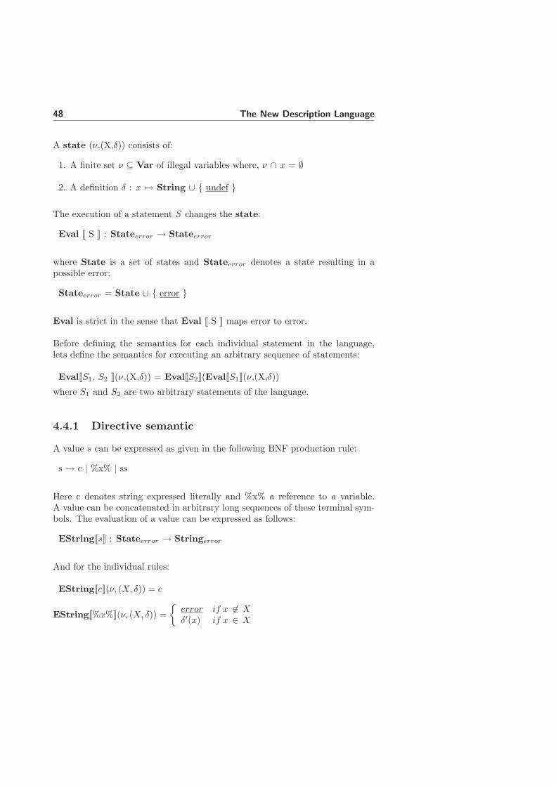
48 The New Description Language
A state (ν,(X,δ)) consists of:
1. A finite set ν ⊆ Var of illegal variables where, ν ∩ x = ∅
2. A definition δ : x 7→ String ∪ { undef }
The execution of a statement S changes the state:
Eval [[ S ]] : Stateerror → Stateerror
where State is a set of states and Stateerror denotes a state resulting in apossible error:
Stateerror = State ∪ { error }
Eval is strict in the sense that Eval [[ S ]] maps error to error.
Before defining the semantics for each individual statement in the language,lets define the semantics for executing an arbitrary sequence of statements:
Eval[[S1, S2 ]](ν,(X,δ)) = Eval[[S2]](Eval[[S1]](ν,(X,δ))
where S1 and S2 are two arbitrary statements of the language.
4.4.1 Directive semantic
A value s can be expressed as given in the following BNF production rule:
s → c | %x% | ss
Here c denotes string expressed literally and %x% a reference to a variable.A value can be concatenated in arbitrary long sequences of these terminal sym-bols. The evaluation of a value can be expressed as follows:
EString[[s]] : Stateerror → Stringerror
And for the individual rules:
EString[[c]](ν, (X, δ)) = c
EString[[%x%]](ν, (X, δ)) =
{
error if x 6∈ X
δ′(x) if x ∈ X
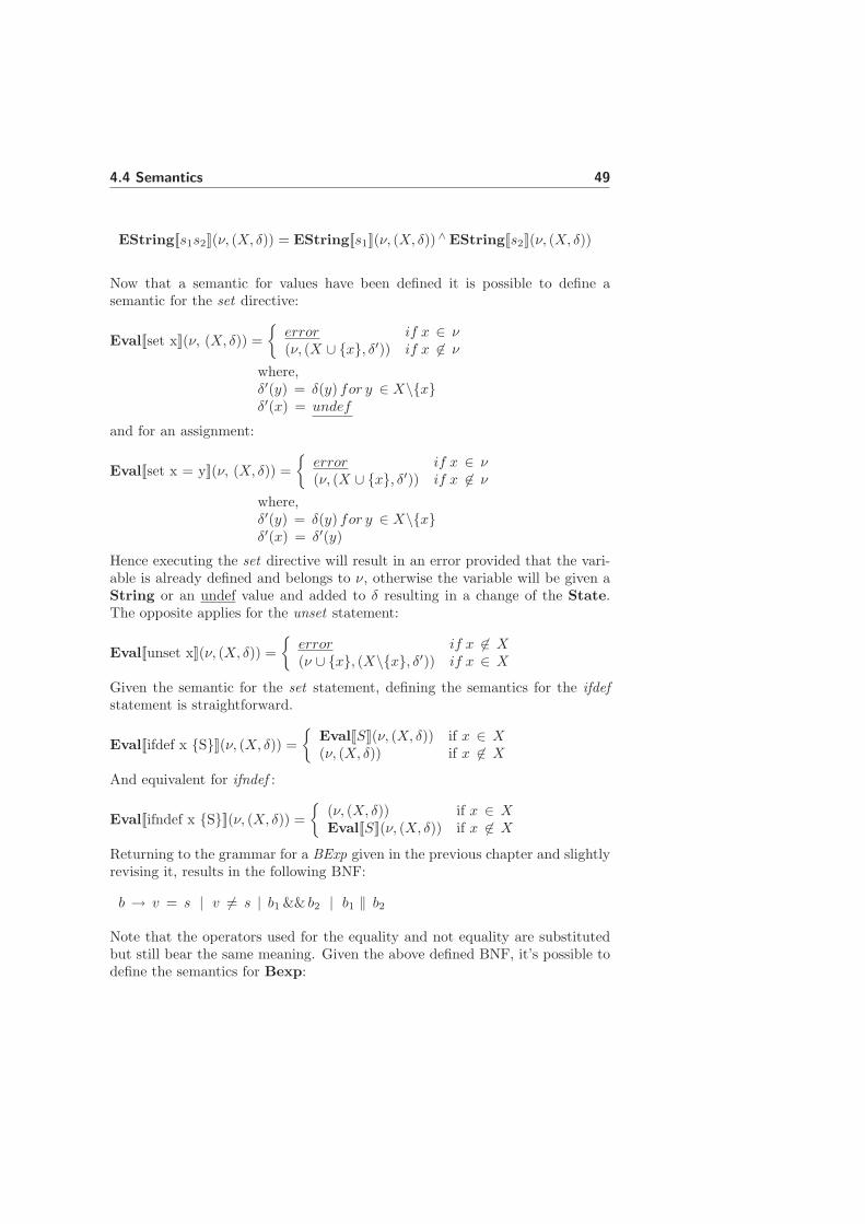
4.4 Semantics 49
EString[[s1s2]](ν, (X, δ)) = EString[[s1]](ν, (X, δ)) ∧ EString[[s2]](ν, (X, δ))
Now that a semantic for values have been defined it is possible to define asemantic for the set directive:
Eval[[set x]](ν, (X, δ)) =
{
error if x ∈ ν
(ν, (X ∪ {x}, δ′)) if x 6∈ ν
where,δ′(y) = δ(y) for y ∈ X\{x}δ′(x) = undef
and for an assignment:
Eval[[set x = y]](ν, (X, δ)) =
{
error if x ∈ ν
(ν, (X ∪ {x}, δ′)) if x 6∈ ν
where,δ′(y) = δ(y) for y ∈ X\{x}δ′(x) = δ′(y)
Hence executing the set directive will result in an error provided that the vari-able is already defined and belongs to ν, otherwise the variable will be given aString or an undef value and added to δ resulting in a change of the State.The opposite applies for the unset statement:
Eval[[unset x]](ν, (X, δ)) =
{
error if x 6∈ X
(ν ∪ {x}, (X\{x}, δ′)) if x ∈ X
Given the semantic for the set statement, defining the semantics for the ifdefstatement is straightforward.
Eval[[ifdef x {S}]](ν, (X, δ)) =
{
Eval[[S]](ν, (X, δ)) if x ∈ X
(ν, (X, δ)) if x 6∈ X
And equivalent for ifndef :
Eval[[ifndef x {S}]](ν, (X, δ)) =
{
(ν, (X, δ)) if x ∈ X
Eval[[S]](ν, (X, δ)) if x 6∈ X
Returning to the grammar for a BExp given in the previous chapter and slightlyrevising it, results in the following BNF:
b → v = s | v 6= s | b1 && b2 | b1 ‖ b2
Note that the operators used for the equality and not equality are substitutedbut still bear the same meaning. Given the above defined BNF, it’s possible todefine the semantics for Bexp:

50 The New Description Language
EBool[[v = s]](ν, (X, δ)) =
{
true if δ(v) = EString[[s]](ν, (X, δ))false if δ(v) 6= EString[[s]](ν, (X, δ))
EBool[[v 6= s]](ν, (X, δ)) =
{
true if δ(v) 6= EString[[s]](ν, (X, δ))false if δ(v) = EString[[s]](ν, (X, δ))
EBool[[b1 && b2]](ν, (X, δ)) =
{
true if Eval(b1) = true and Eval(b2) = true
false if Eval(b1) = false or Eval(b2) = false
EBool[[b1 ‖, b2]](ν, (X, δ)) =
{
true if Eval(b1) = true or Eval(b2) = true
false if Eval(b1) = false and Eval(b2) = false
where EBool denotes the evaluation of a boolean expression:
EBool[[b]] : Stateerror → Boolerror
Given the semantics for boolean expressions, defining the semantics for if state-ments is straightforward:
Eval[[if b {S}]](ν, (X, δ)) =
{
Eval[[S]](ν, (X, δ)) if Bexp[[b]] = true
(ν, (X, δ)) if Bexp[[b]] = false
The semantics for an elseif branch is identical to an if statement. Howeverthe dangling elseif’s and else branches are not executed if one of the precedingconditionals have evaluated to true.
The include statement involves importing a file and executing its contents withthe so far obtained illegal variables ν and the variable definitions δ. The se-mantics for the statement can be expressed as given in the following somewhatinformal rule:
Eval[[include file]](ν, (X, δ)) = Eval(S)(ν, (X, δ))
where S denotes the contents of file.
The example below illustrates how the above defined semantics for the set andunset statements is applied. In the example, ”{...}” denotes the set of illegalvariables and ”[...]” denotes the map from legal variables to values.

4.4 Semantics 51
{} []set X
{} [X 7→ undef]set Y = A
{} [X 7→ undefY 7→ ”A” ]
set Z = %Y%{} [X 7→ undef
Y 7→ ”A”Z 7→ ”A” ]
set Z = %Z%%Z%C{} [X 7→ undef
Y 7→ ”A”Z 7→ ”AAC” ]
unset Y{Y} [X 7→ undef
Z 7→ ”AAC” ]
4.4.2 Section semantic
The most interesting part of the section grammar to define a formal semanticfor are the sections listing files, simply because the main part of the descriptionfiles syntax reside in such sections. As seen from the BNF in appendix E eachrow in these section define a file. Some sections also defines the possibility ofexpressing zero or many file specific options to the file. In addition to the filelisting sections there are sections that provide functionality to override a filelisted in a file list section, the file list modification sections. A file listed in afile list modification section modifies the contents of a previously defined filelist section in the sense that it is removed from the list of defined. Hence thesemantic for these two types of sections resembles the semantic for the set andunset directive to great extent. But instead of having a variable name mappingto a value we have a file mapping to a possible file option and instead of blockinga variable for further use, a file is removed.
A file listed in a file list section, simplifying the grammar slightly, can be ex-pressed as a string s followed by another string s, the first string mapping tothe file path and the second string mapping to a possible options to the file. Itshould be mentioned that the majority of the sections merely list files withoutany options but the semantic is expressed assuming options to all sections whichgives a more general semantic. If the option is empty, then the entry in the filelist is also empty.

52 The New Description Language
IncSec → File | File IncSec
File → s NL | s s NL
The evaluation of a file listed in a file list section, here denoted with EInc-
Sec, will result in the file path and the option being added to a list of filedescriptions, fileDescr*:
EIncSec[[s1]](ν, (X, δ)) =< (EString[[s1]](ν, (X, δ)), ”” >
EIncSec[[s1, s2]](ν, (X, δ)) =< (EString[[s1]](ν, (X, δ)), EString[[s2]](ν, (X, δ))) >
EIncSec[[File IncSec]](ν, (X, δ)) =< EIncSec[[File]](ν, (X, δ)) ∧ EIncSec[[IncSec]](ν, (X, δ)) >
EIncSec[[IncSec]] : State → fileDescr*
where
fileList = fileName × Options
In extension of having the possibility to list a file it is possible to subsequentlyremove the file from the list. The grammar is simply a string denoting the fileto be overridden:
ModSec → File | File ModSec
File → s NL
The semantics for a file listed in a file list modification section is simply re-moving it from the list of files. Hence:
EModSec[[s]] : fileList* → State → fileList*
and
EModSec[[dels]]fileList* = fileList*\{s}
where del denotes the deletion of a file s from the list of files (fileList).
Finally an example to illustrate the defined semantic for file list sections and filelist modification sections. As in the previous example ”{...}” denotes the set ofoverridden files and ”[...]” denotes the list of files.

4.5 Summary 53
{} [][SourceFiles].\dir\file1.c.\dir\file2.c AVR=(-z9).\dir\file3.c
{} [.\dir\file1.c , ””.\dir\file2.c , ”AVR=(-z9)”.\dir\file3.c , ”” ]
[-SourceFiles].\dir\file1.c {.\dir\file1.c} [.\dir\file2.c , ”AVR=(-z9)”
.\dir\file3.c , ”” ]
The file list modification sections are always evaluated last, hence would ”[-SourceFiles]” in the example have been followed by another ”[SourceFiles]” list-ing file.c again it would still not be not be part of the file list.
4.5 Summary
This chapter has described the new description language (NDL) which is basedon the current implementation (CDL). The syntax of CDL is to great extentkept as it is in NDL. The main difference is that NDL has a formal definitionof the grammar whereas CDL does not. In other words NDL implements amore strict syntax with defined rules and constrained behaviour. Another maindifference between CDL and NDL is that the latter has a whole new way ofprocessing the files and parsing the language. Where CDL is implemented in ahandwritten parser, NDL uses a compiler compiler tool generated parser. Alsothe way the files are processed differ between the two languages. When it comesto the semantic of the language it is practically identical with one key difference;the variable semantic is changed regarding the rules concerned with the variablesscope rules.
The main differences between the old and the new language are summarized intable 4.2.
Hence the functionality provided by CDL is kept intact. The key difference isthe way the languages are defined and handled.

54 The New Description Language
CDL NDL
No formal grammar Formal grammarFlat file structure File tree intactExtensive Perl availability Constrained Perl availabilityHand written parser Generated parserGlobal variables Constrained variable scopeFile parsed multiple times File parsed one time
Table 4.2: Main differences between CDL and NDL

Chapter 5
The Analysis Tool
5.1 Introduction
One of the objectives of this master thesis project is to develop a analysis toolcapable of performing syntactic and semantic analysis on the new language inaddition to different analysis on individual description files or a file tree. Thischapter describes the detailed design and implementation of that tool.
One of the prerequisites when implementing the tool is that it should be partlygenerated with the help of a compiler compiler tool as opposed to the hand-written parser that exists today. A compiler compiler, as the name implies, isa tool that support the development of a compiler. Such a tool typically takesa formal grammar and generates the parser and possibly also the syntax tree.This simplifies the development process significantly and reduces many risk thathaving a handwritten parser produce. An overview of how the chosen compilercompiler tool works is given in appendix D.
This chapter is structured as follows; section 5.2 describes the main objectivesof the analysis tool, section 5.3 gives an overview of the analysis tool design,section 5.4 to section 5.6 describe the individual parts of the tool, which includesa preprocessor, front end and back end.
5.2 Tool objectives
The main objectives of the analysis tool is to issue warnings and errors mes-sages where the language is violated regarding its syntax and semantic. Thesemessages can be categorized into three different levels of errors:
1. Lexical errors, are thrown by the lexer whenever the JavaCC token

56 The Analysis Tool
manager detects a problem. See examples of errors in section 5.5.1.
2. Syntactical errors, are thrown by the parser whenever it detect a prob-lem in the input token stream that violate the grammar of the language.See error examples in section 5.5.2.
3. Semantic errors, are issued by the semantic analysis when constructsthat do not follow the language semantic are found. See error examplesin section 5.6.3.
Another objective of the tool is to implement different analysis of the descriptionfiles. The analysis incorporated into this version of the tool are:
• File analysis, analysis of the file names that reside in the file list sections.A more detailed description is given in section 5.6.5.
• Variable analysis, analysis of the variables that reside in the descriptionfiles. A more detailed description is given in section 5.6.6.
All three parts of the tool issues errors and warnings when constructs thatviolate the defined syntax or semantic is found. The lexer and parser in thepreprocessor and front are both capable of finding lexical error and syntacticalerror whereas the semantic analysis pinpoints constructs that violate the definedsemantic. A lexical error is
5.3 Tool architecture
The analysis tool architecture resembles the design of a compiler to great extent.The general notions behind the design of compiler is introduced in appendix C.2.and figure C.1 shows the typical phases. The analysis tool is however not acomplete compiler. It is not of interest to translate the source text into machinecode and therefore the back end part of a compiler will not be further elaboratedhere. The part of interest when implementing the analysis tool is mainly thefront end part, with the exception of the intermediate code generation phase.Revising figure C.1 to fit the purposes of the analysis tool, figure 5.1 depicts thephases applicable.
An elaborative and detailed architecture sketch is illustrated in figure 5.2. Thephases needed to implement the analysis tool is mainly the typical front endpart of a compiler. However this notion have been revised when defining thedesign of the analysis tool. Here the front end part have been split into onefront end and one back end extended with a preprocessing step. The front endpart takes care of parsing and tree building while the back end is responsible

5.4 Preprocessor 57
description file
lexical analysis
syntactic analysis
semantic analysis
errors and analysis output
front end
Figure 5.1: Phases in the analysis tool mapping to a typical compiler
for the semantic analysis. Hence the notions from section C.2 is slightly revisedbut not the overall meaning.
The analysis tool is made up of three separate parts. The input description fileis first passed to a preprocessor responsible for performing some initial parsingof the file to resolve some constructs available in the language. The preprocessedfile is then send to the front end which implements the actual lexer and parser.The front end builds an AST representation of the file which is passed on tothe back end. The back end implements the semantic analyser but also differentanalysis of the file.
All three parts of the tool issues errors and warnings when constructs thatviolate the defined syntax or semantic is found as described in section 5.2. Thelexer and parser in the preprocessor and front are both capable of finding lexicalerror and syntactical error whereas the semantic analysis pinpoints constructsthat violate the defined semantic but also a file and variable analysis.
5.4 Preprocessor
As described in chapter 3 and further revised in chapter 4 the language offersa macro directive identified with the keyword ”!define” which makes it possibleto assign multi line values to a macro which can then be referred later in thefile. The value can theoretically consist of any type of expression adhering tothe description language. However having the actual parser taking care of thistype of construct would be messy. It would be more sufficient if the parseronly handles the expanded macro value and don’t have to bother about themacro syntax, generally because the parser not knowing what actually resides

58 The Analysis Tool
Description file
Lexer Parser
Preprocessor
Lexer Parser
Front end
Preprocessed file
Semantic analysis
Back end
AST
errors and analysis output
description file
Analysis tool
lexical and syntactical errors
Figure 5.2: Analysis tool architecture
in the macro causes an insufficient ambiguity in the AST. Therefore it is feasibleto introduce a pre parsing step or a preprocessor that can handle the macroconstructs and expand them before the main parser continues processing thefile. Figure 5.4 shows the functionality provided by the preprocessor step.
Preprocessor Descr. file Preprocessed
descr. file Parser
Finds all macros definition and expands their
references
Figure 5.3: The preprocessor step
The preprocessor takes a description file as input and produces a preprocessedfile which is passed on to the front end. The preprocessor searches the file formacro definitions and macro references. The macro values are put in a list andon the encountering of a macro reference the macro value is extracted from thelist and replaces the macro references. Hence in the preprocessed file all macrooccurrences are removed and replaced with blank lines and all references withtheir corresponding value. An example is depicted in figure 5.4.

5.4 Preprocessor 59
!define file_list = << END_OF_DEF .\dir\file1.c .\dir\file2.c .\dir\file3.c END_OF_DEF
[SourceFiles] %file_list
[SourceFiles] .\dir\file1.c .\dir\file2.c .\dir\file3.c
Orginal file Preprocessed file
Figure 5.4: A preprocessed file and corresponding non preprocessed file
Since the references might be expanded with multi line values the line numberingof the original file might be corrupted in the preprocessed file and would resultin an possible error pointing to the wrong line in the original file. This has beensolved by the preprocessor instrumenting the code with a line offset constructrepresenting the number of lines in the macro, which is then handled by the frontend. The line offset integer is simply subtracted from the actual line numberin the front end resulting in the correct line being referred to when finding anerror. An example is illustrated in figure 5.5.
1 !define file_list = << END_OF_DEF 2 .\dir\file1.c 3 .\dir\file2.c 4 erronous construct! 5 END_OF_DEF 6 7 [SourceFiles] 8 %file_list 9 10
1 2 3 4 5 6 7 [SourceFiles] 8 !line_offset 3 9 .\dir\file1.c 10 .\dir\file2.c 11errornous construct!
Orginal file Preprocessed file
Error, on line (11 - line_offset = 8)
Figure 5.5: The solution to corrupted line number
The language also offers the possibility of dividing long lines into several usinga special continuation mark denoted by ”!\” which is placed last on the lineresulting in the following line being concatenated with the preceding one. Thislanguage construct is also handled by the preprocessor, simply concatenatingall occurrences of continuing lines and replacing them with blank lines.
60 The Analysis Tool
5.5 Front End
The front end part of the analysis tool contains the actual parser of the languagetogether with a lexer. The front end parses the file following the rules dictatedby the grammar and generates an AST representation of the file contents.
The lexer and parser are generated with the help of a compiler compiler. Thecompiler compiler chosen to generate the core of the analysis tool is the JavaCompiler Compiler (JavaCC) [2]. JavaCC is an open source project and thecomponents it generates are pure java code. The motivation behind the choiceof this particular compiler compiler is that it is open source but the fact that itis Java based is also a factor, because EMP is planning to move their softwaredevelopment environment to the Eclipse platform which also is Java based andtherefore making the analysis tool integration with the software environmenteasier. It is recommended to read appendix D which gives an overview of JavaCCbefore continuing.
The grammar described in chapter 4 resides in a perfect theoretical world. Thereal world is however not quite that utopian and applying the grammar straighton to the compiler compiler would not suffice. The grammar has to be modifiedto some extent to fit the real world. The subsequent sections will elaborate onthe implementation of the front end and the different problems arising whentrying to apply the grammar into the tool.
5.5.1 Lexical analysis
The big issue when defining the tokens for the lexer has been to match a stringvalue to a variable correctly since it can basically be any sequence of charactersand there are no defined delimiters denoting the start and end of the string.
A first approach was simply to define a regular expression matching anythinguntil a new line is encountered:
TOKEN:
{
< VALUE: (~["\r","\n"])* >
}
The ”˜” character tells the lexer to match anything but the characters enclosedin parenthesis. This solution however proved to be very dangerous because itis very likely that the lexer will match every line in the file as a VALUE token.To solve this the JavaCC notion of lexical states can be used. Every timean assignment operator is found corresponding to a set statement the lexer isforced to switch to another lexical state (e.g. IN VALUE) where only the tokenVALUE is applicable:

5.5 Front End 61
<IN_VALUE>
TOKEN:
{
< VALUE: (~["\r","\n"])* > : DEFAULT
}
This solution however implies that further lexical states have to be introducedbecause moving to the IN VALUE state should only be performed when theassignment operator is found in a set statement. Also the value is not alwayssimply a string. It can also be a variable reference or a function which the abovegiven token definition would match but leaving no trace in the resulting AST ofsuch occurrences, resulting in a unwanted complexity when resolving the actualvalue. Having many lexical states also makes the reading of the grammar filesignificantly more difficult and debugging harder. Another setback using anextensive amount of lexical states is the rapid growth of the generated parser interms of its size, which at least for some of the intermediate solutions elaboratedon in this thesis gave a unrecoverable memory overflow error in the compiler. Itis therefore feasible that the final solution uses as few lexical states as possibleand avoids the ”match everything” token defined above.
Therefore, instead of defining one single token for the matching of a value, manytokens are used that each define a single character. Each character matched bythe lexer is then concatenated together by the parser to form the original string.When implementing such iteration over tokens, the JavaCC feature of writingpure Java code productions is very sufficient. When the parser encounters anassignment the suitable Java method is invoked taking care of the value parsing,described by the following somewhat simplified code:
void matchValue() {
Token t;
String s;
while(true) {
t = getToken(1);
if(t = NL) {
stringLiteral(s);
break;
}
else if(t == VARIABLE_REF) {
stringLiteral(s);
s = "";
variableReference();
}
else if(t == FUNCTION_IDENTIFIER) {
stringLiteral(s);

62 The Analysis Tool
s = "";
function();
}
else {
s = s + t;
}
getNextToken();
}
}
The lexer defines an API that enables access to to the token sequence directly.Examples of such API routines are getToken(int index) and getNextToken()
used in the code sample above. getNextToken() consumes a token from theinput stream while getToken() merely peeks at index-th token from the currenttoken ahead in the token stream. The keywords denoted by capital letters inthe matchValue() method are the identifying names for defined tokens. Themethod iterates over the token stream until a new line is found (NL). If a variablereference or function is found the suitable BNF production rule is invoked,otherwise the token is considered a part of a string and concatenated with theprevious token.
This solution avoids using lexical states as well as tokens matching everything.The matchValue method is also invoked when making comparisons in a booleanexpression to a conditional statement.
However it should not be regarded as an disadvantage to use lexical states sincethey provide a very powerful feature to the lexer. The recommendation is notto use to many of them. The lexers final solution also has lexical states, moreprecisely two, not counting the DEFAULT state. When finding a section thathas no defined grammar it is desired to match a whole line as one token andthereby using ”match everything” token. To disable the possibility of the parsermatching other expressions in the file as such a token it is sufficient to divide thematching of section syntax into two states. The DEFAULT states matches thesection syntax where a grammar is defined and IN MISCSECTION matchingthe rest of the sections. However the directives should still be parsed in these”miscellaneous” sections. Therefore the tokens needed in the directives are alsoapplicable in the IN MISCSECTION state. Whenever a miscellaneous sectionis found the lexer forces a switch to IN MISCSECTION. In IN MISCSECTION,besides the tokens needed by the directives, the following token is applicable:
<IN_MISCSECTION>
TOKEN :
{
< MISC_STMT : ~["[","!","%"] (~["\r","\n","%"])* >
}

5.5 Front End 63
This token matches everything until new line except those tokens beginning with”!” denoting the beginning of a directive, ”[” denoting the beginning of a sectionor ”%” marking the beginning of variable reference. Once a new section is found,depending on the type of section, the lexer either moves to the DEFAULT stateor stays in the IN MISCSECTION state.
The second lexical state implemented in the lexer is called COMMENT NA,which is short for comment not applicable. Comments in the description lan-guage are normally denoted with the ”#” character which marks the start of thecomment. However the comments are not entirely context free. Actually SDEonly considers a comment to be a comment if it is stated in the beginning of aline. Comments in the new description language are defined as a SKIP token,which means that comments will simply be skipped by the lexer wherever theyare stated and will not be passed to the parser. This is however not feasibleconsidering that the ”#” character should not always be matched as the startof the comment. This is considered particularly important when matching avalue or the arguments to a file option. Therefore when parsing these rulesthe parser forces the lexer to switch to new state, COMMENT NA, where thecomment token is not applicable and thereby not matching the ”#” characteras a beginning of comment. However anywhere else in the grammar commentsare applicable. Being able to force a switch in the lexer from the parser impliesthat the lexer and parser are not two sequential steps but rather execute inparallel. The lexer is however always ahead of the parser. Forcing a switch oflexical state from the parser should therefore be considered with care becausethe lexer might be well ahead of the parser owing to lookahead and the switchto the new lexical state might not be applied to the token one had in mind.
The implementation of the rest of the lexer is pretty straightforward. Sincethe regular expressions for the tokens are matched in their order of occurrencein the grammar file it is important that tokens are defined in specific order toensure the correctness of the lexer. The order in which the tokens are definedare described below:
1 Keywords
2 Skip tokens
3 Identifiers
4 New line
5 Single characters
6 ”Match anything” token
Hence all keywords in the language, such as ”!if” or ”[SourceFiles]” are put inthe beginning since it is imperative that the language keywords are not matchedas anything else.

64 The Analysis Tool
Error reporting
Whenever the token manager in JavaCC detects a problem it throws an excep-tion of type TokenMgrError. This occurs if a token does not obey any of therules dictated by the lexer, for example if the token contains a character thatdistort the meaning of the token. For example:
!s&et A
will cause the lexer to print the following error message:
Lexical error at line 6, column 7. Encountered: "e" (105), after : "&"
5.5.2 Syntactical analysis
The syntactical analysis or the parser is concerned with transferring the gram-mar rules defined in section 4.3 to the JavaCC grammar file.
Avoiding left recursion
Although the grammar was considered not have any left recursion and no rewrit-ing of the production rules are necessary it could still be interesting in elaborat-ing on a grammar that would. Consider the revised and more compact writingof the BNF production for a boolean expression:
b → v = s | v 6= s | b&& b | b ‖ b
This BNF would result in JavaCC throwing an error that the grammar containsleft recursion because the non-terminal b contains a recursive reference to itselfthat is not preceded by something that will consume tokens. The parser pro-duced by JavaCC works by recursive descent. Left-recursion is banned to pre-vent the generated subroutines from calling themselves recursively ad-infinitum.The left recursion is prevented by using the rules defined in section 4.3. Theserules have no recursive calls to themselves and thus no left recursion.
Alternative approaches
Before defining the final solution of the description language parser, a couple ofother approaches where tried out but finally rejected. A first approach was touse two separate parsers, one for the directives and one for the sections. The di-rective parser simply left the section syntax intact only analysing the directives.The section code where then extracted from the generated AST and fed backto the section parser. The section parser was initialized with different lexicalstates depending on the type of section to be parsed. The section AST wasthen added to the original AST build by the directive parser. This approach isillustrated in figure 5.6.

5.5 Front End 65
Directive parser
Section extracting
AST
Section parser
AST
Section text
Merged AST Description
file
Figure 5.6: The approach of having two parsers
This approach however is a bit redundant since the section parser still have toparse the directives residing in the sections. So both parsers had to implementthe same grammar to some extent, namely the directive grammar.
Also a more general grammar was elaborated that simply allowed the sectionspecific syntax to be context free, meaning that all special syntax residing inthe sections could be written anywhere and the analysis whether or not an ex-pression belonged to the right section was left to back end to resolve. Havinga general grammar gives a fairly easy parser and but does imply that a lot ofwork should be done by the semantic analysis in the back end.
Final solution
Although having a general grammar for the parser would provide an easilyimplemented parser, it’s disadvantages was still considered to overshadow it’sadvantages. Having a grammar that constrains the parser to only consider thesection specific syntax in it’s right context is the final and chosen solution sinceit can resolve a lot of errors on a early stage, releasing the back end from theburden of having to check every single expression with respect to to its context.
The solution is however not as trivial as the more general one. If the possiblestatements in the grammar were free from recursive calls it would be fairlysimple. Then each section could invoke a BNF production that only allowed thedesired syntax, illustrated in the sample code below for a file list section:
void Section() :
{}
{
...
<INCLUDEFILES> <NL> FileListStmt()
...
}

66 The Analysis Tool
void FileListStmt() :
{}
{
(FileList() | Directive())*
}
void FileList() :
{}
{
FilePath() <NL>
}
However problem arises when Directive() is a conditional. The branch to theconditional could basically be any statement in the grammar, which is not suit-able. The available BNF productions that can be invoked from the conditionalsomehow have to be forced to be only the ones allowed for the section that isbeing parsed. To solve this a state for each section class is introduced, whichare not to be confused with the notion of lexical states. The state, which isjust an integer constant, is passed on to every directive that is invoked fromthe applicable section class production. If the directive is a conditional and abranch is found the state is used to force the parser to only parse the produc-tions available for the given section. Below the example from above is extendedwith the notion of section states:
void Section() :
{}
{
...
<INCLUDEFILES> <NL> FileListStmt()
...
}
void FileListStmt() :
{}
{
(FileList() | Directive(FILELIST))*
}
void FileList() :
{}
{
FilePath() <NL>
}

5.5 Front End 67
Here an integer, FILELIST, denoting that the section is a file list section ispassed on to the directive production:
void Directive(int sectionState) :
{}
{
IfStmt(sectionState)
| IfdefStmt(sectionState)
| IfndefStmt(sectionState)
| SetStmt()
| UnsetStmt()
| IncludeStmt()
| OptionsStmt()
| LineOffset()
| <NL>
}
Each conditional statement (if, ifdef and ifndef) calls a Java code productionwith the section state integer, which acts as a switch invoking the appropriateBNF production depending on the given state:
JAVACODE
void sectionStmt(int sectionState) {
switch(sectionState) {
case FILELIST: FileListStmt(); break;
...
}
}
This way the parser is forced to only allow the section specific syntax for thegiven section. The implementation is not entirely straightforward since theused Java code productions (like sectionStmt), are considered a black boxby JavaCC which somehow does its task and the normal regular expressionconstructs can’t be invoked on them, for example constructs like repetition andoptional expansion. These implementation work arounds will however not befurther elaborated here.
The rest of the parser implementation is pretty straightforward mapping almostwithout exception to the grammar defined in chapter 4.
Error reporting
Whenever the parser detects a problem it throws an exception of type ParseException.This occurs if the token stream provided from the lexer to the parser does notobey the rules dictated by the grammar. An example is if the the booleanexpression to an if directive is corrupt:

68 The Analysis Tool
!set = A
Here the variable identifier is clearly forgotten and the parser will print thefollowing error message in the case of the above construction:
Encountered "=" at line 4, column 6.
Was expecting one of:
<OPT> ...
<IDENTIFIER> ...
The error message is informing us that the parser is expecting either an option(¡OPT¿) or an identifier to proceed the assign character (”=”). Another exampleis if for example the section name is misspelled:
[SorseFiles]
This will produce the following error output from the lexer:
Encountered "[" at line 2, column 1.
Was expecting one of:
<EOF>
"!if" ...
"!set" ...
"!unset" ...
"!ifdef" ...
"!ifndef" ...
"!include" ...
"!options" ...
"!line_offset" ...
"[SourceFiles]" ...
"[IncludeFiles]" ...
"[BuildFiles]" ...
"[LinkFiles]" ...
...
where the parser is telling us that another token has to be used, namely theones dictated by the grammar production rule.
5.5.3 Building the AST
With the use of JJTree it is possible to, besides the generated parser, to producean AST representation of the parsed file as explained in section D.4. Since it is

5.6 Back End 69
not desired to produce a parse tree node for each nonterminal in the grammarthe default behaviour of JJTree has been overridden and only nonterminalswhere it is explicitly stated generates a node.
As explained in section D.4, JJTree provides a very simple way of generatingAST representations by simply invoking the ”#” character followed by the nameof the node with a possible argument. Implementing the AST has been straight-forward. Given below is an example of description file implementation and theAST it produces following the rules implemented in the grammar file.
!set A = 1
!set B = 2
!include .\file.cfg
!if A == 1 && B != 2
!set C = 1
!elseif A == 1 || B == 2
!set C = 2
!else
!set C = 3
!endif
[SourceFiles]
.\dir\file1.c
.\dir\file2.c AVR=(-z9)
[MakeRules]
copy #path $(INC)#name#ext >nul
results in the AST depicted in appendix F. Every children is denoted by thenode being indented relative to its parent. As can be seen every section is a childdirectly to the start symbol and all syntax residing in the section is regardedas children to that section. The ”[MakeRules]” section, which is such a sectionwhere no formal grammar has been defined, is simply left untouched.
5.6 Back End
The back-end is the part that traverses the AST and outputs error messages forsyntactically and semantically incorrect constructions in the description file asdescribed in section 5.2. The back-end is also responsible for producing analysisresult when applicable. Figure 5.7 depicts a general notion of the back end.
Input to the analysis tool back-end is the generated AST, which is traversed a

70 The Analysis Tool
Semantic analysis
Variable Analysis
File Analysis
Back End
semantic errors
analysis output
analysis output
Figure 5.7: Block diagram depicting the back end
number of times to produce the analysis tool output. For this purpose a designpattern called the visitor pattern technique is suitable. The back end is easilyextendable with new back end applications, which handle the AST differently.The different back ends each produce different output, i.e. their task is to checkdifferent semantic aspects of the language.
Besides the visitors classes the back end also contains a number of help classes.A class diagram of the back end is depicted in figure 5.8.
5.6.1 The Visitor Pattern Technique
In the context of JavaCC and JJTree, the parser parses the description file andreturns a handle to a node that is the root of an AST; that AST representsthe input parsed. After the parser and tree building are done, the AST thentypically needs to be traversed and processed in one or more ways. Each ofthese operations involves walking the AST, starting at the root and executingsuitable code for each type of AST node encountered. It is here the visitordesign pattern [7] comes in handy. A visitor is an object that ”visits” the ASTand does something useful with the information in the AST. The visitor designis an elegant and flexible way to implement such operations on the AST. Thedifferent back end applications in the analysis tool are implemented accordingto the visitor pattern technique. The visitor pattern technique is suitable whenit is desirable to perform some operation on every object in a structure ora collection of objects (the AST) and JJTree provides support for this. Byinvoking the proper option in the grammar file JJTree will generate the visitordesign support:

5.6 Back End 71
+reInit()
DescrLangParser
+runVisitors() +runSemanticVisitor() +runFileVisitor()
BackEndManager
1 1
+visit()
InitVariantMatrixVisitor
+visit()
SemanticAnalysisVisitor
+visit()
FileAnalysisVisitor
+error() +warning() +information() +dumpMessages()
BackEndError
1
1
+addAST() +getAST() +astExists()
ASTTable
1
1
1
1
1
0..*
1
0..*
+visit()
VariableAnalysisVisitor
1
0..*
Figure 5.8: Class diagram depicting the back end design
Options {
VISITOR = true;
}
When this option is set to true, JJTree will automatically do two things:
1 Insert a jjtAccept method into each of the AST node class definitionsthat it generates.
2 Generate a Visitor interface (a standard kind of Java interface) with anempty method for each type of AST node used in the grammar.
When implementing a back end application (i.e. visitor) it must implement theautomatically generated visitor interface and the visitor implemented must alsocontain a handwritten visit() method to deal with each type of AST nodethat the grammar generates. This is illustrated in the figure 5.9.

72 The Analysis Tool
DescrLangParserVisitor.java … One abstract “visit” metod for each concrete AST class …
AST classes
Delegate computation
An “accept” method is added to each AST class
Visitor1.java Visitor2.java … Impl. of the visit methods …
… Impl. of the visit methods …
Figure 5.9: Vistor pattern overview
Figure 5.9 illustrates that it is possible to define an arbitrary number of visitorsthat operate on the elements of an object structure without modifying the classesof the elements on which it operates.
Once the parser has parsed the file provided to it, it passes back a handle to theroot node of the created AST, which can be stored using the construct:
ASTStart ast = parser.Start();
ast now holds an instance of the root node of the newly created AST. It is nowpossible to instantiate the suitable visitor:
DescrLangParserVisitor fv = new FooVisitor();
ast.jjtAccept(fv,null);
The visitor object is passed to the jjtAccept method of the AST root node. Thesecond argument, null, is not used. The call to jjtAccept is telling the node to”accept” the indicated visitor. The automatically generated jjtAccept methodlooks like this:
/** Accept the visitor. **/
public Object jjtAccept(DescrLangParserVisitor visitor, Object data) {
return visitor.visit(this, data);
}
As can be seen the method just does a call back to the DescrLangParserVisitoritself:

5.6 Back End 73
visitor.visit(this, data);
The method passes to the visitor’s visit method a handle to the AST node itself(this), and a handle to the Object data, which in the case of the analysis toolalways will be null. What the jjtAccept() method in ASTStart() effectivelydoes is send a message to the indicated Visitor, saying ”here is a handle to me(which will be of type ASTStart), do whatever you are supposed to do with anAST node of my type”. The visitor is a whole collection of overloaded visit()methods, one for each AST node type. The particular visit() method in theVisitor that will be invoked is the one whose first argument matches the type ofcalling node. The way the visitor is instantiated and how it traverses the ASTis depicted in the sequence diagram in figure 5.10.
Parser ASTStart
FooVisitor() FooVisitor
jjtAccept(fv:Object, null:Object)
visit(ASTStart:Object,data:Object)
ASTChild
jjtAccept(fv:Object,null:Object)
visit(ASTChild:Object,data:Object)
jjtAccept(fv:Object,null:Object)
visit(ASTChild:Object,data:Object)
Figure 5.10: Traversing the AST with a visitor
The root node of the AST, ASTStart, which is the obvious starting point in-vokes its visit() method in the visitor by passing a reference to itself. Thisvisit method will iterate over all its children and accept them (depicted in thefigure 5.10 as the object ASTChild), forcing their respective visit() methodsto be invoked. Each node in the AST will recursively traverse its possible chil-dren the same way until all nodes have been visited. Here follows an exampleof a visit method:
public Object visit(ASTInclude node, Object data) {

74 The Analysis Tool
Node n;
String file = "";
for(int i = 0; i < node.jjtGetNumChildren(); i++) {
n = node.jjtGetChild(i);
if(n instanceof ASTFilePath) {
file = (String)n.jjtAccept(this,null);
}
else {
n.jjtAccept(this,null);
}
}
return data;
}
This is the visit method for the node built when an include directive is parsed.The method iterates over its children and when finding a children of type AST-FilePath the node is accepted and its visit method is invoked, implementinglogic to resolve the file path to be included and returning it to ASTInclude.
5.6.2 Recursive analysis
It is desired that the analysis tool is able to perform checks on the entire filehierarchy of description files. In order to obtain this functionality all files haveto recursively be searched for constructions that include other files (i.e. eithervia the Sub-module concept or the include directive).
The AST is therefore traversed (with a suitable visitor), starting with the ASTbuild from input file to the parser, in search for include clauses. If a module ortarget include is found the parser will be re instantiated from inside the visitorwith the file to be included in the file tree. The parsers parses the file, buildsthe AST, and then a new visitor will be instantiated traversing the new AST inthe same fashion for inclusions. This procedure will repeat itself until all fileshave recursively been searched and an AST have been build for all the files inthe file hierarchy, identified by the input file.
The behavior is slightly different when it comes to files included via the includedirective. These files are considered a logical part of the files from which they areincluded. Therefore, they are parsed they same way as above (by re instantiatingthe parser) but their AST is not passed to a new instance of the visitor. Insteadthe AST is added to the AST being traversed as a child to the node where theinclude is found.
A visitor resumes traversing its AST once all its leaf files have been traversedand searched for include statements. An example of how the module and target

5.6 Back End 75
includes are handled is illustrated in the sequence diagram figure 5.11.
Parser Visitor1 Visitor2 Visitor3
AST
AST
AST
File
File
Visitor4
File
AST
Figure 5.11: Building the file tree
In figure 5.11 File is an arbitrary module or target description found in the ASTbeing traversed by the visitor.
It should be mentioned that this version does not constitute any checks regardingcircularities in the file tree, meaning checks to find if file includes another file thatrecursively includes the initial file which will cause an infinite loop of inclusionsas illustrated in figure 5.12.

76 The Analysis Tool
!include file2.cfg
!include file1.cfg
file1.cfg
file2.cfg
Figure 5.12: Infinite loop of inclusions
5.6.3 Semantic analysis
The semantic analyser is implemented in a visitor named SemanticAnalysisVisi-tor (SemanticAnalysisVisitor.java). This visitor besides implementing checksto find errors violating the language semantic, also implements the recursiveanalysis to identify the file tree as described in section 5.6.2. Whenever an in-clude file is found the parser is invoked ending with a AST being build which iseither added to the existing or left separate.
To be able to ensure that the semantic rules are followed as well as being able tospot other errornous constructions in the files the SemanticAnalysisVisitor haveto able to resolve and evaluate the nodes of the AST. This includes evaluat-ing conditionals, resolving file paths, executing predefined functions and storingvariables and resolving them when referenced. It is feasible that all visitors in-corporated in the analysis tool also can implement this functionality. Thereforeall additional visitors can extend SemanticAnalysisVisitor and thereby access-ing the functionality without having to implement it themselves. Wherever itis feasible to override the implementation of the SemanticAnalysisVisitor thevisitor can simply implement it’s own version of the suitable visit method forthe AST node.
Handling variables
As explained in section 4.2.5 the variable scope is considered to be from thepoint of definition and further down the file tree. In the file the variable is beingdefined it is considered over ridable while in a leaf file it is constant. Semanti-cAnalysisVisitor therefore implements two tables inhabited by the variables, toensure the variable scope and semantic. One being the localVariables, obvi-ously taking care of the local and over ridable variables. On the first encounter of

5.6 Back End 77
the variable it is put in this table. The other table is called constantVariables
and all variables in this table are considered constant and may not be overrid-den. When a module or target include is found the contents of localVariablesare merged into constantVariables and send as an argument to the includedmodule or target ensuring that the variables are visible in the leaf files.
The chosen data structure for the variable tables is hash table with the variablename as the key and the variable value as the value. If the variable is definedwithout a value it is set to an empty string. Using a hash table ensures easylookup once the a variable is referenced.
SemanticAnalysisVisitor also implements a third table; illegalVariables, map-ping to the variables having been blocked by the unset directive. If a variablesis unset it is removed from the tables containing legal variables and put inillegalVariables.
Whenever a variable is referenced or used, the visitor checks according to thevariable semantic if the construction is correct, otherwise an error is issued.Figure 5.13 gives an example on how the variables are handled.
!set A = 3 !set B = 4
[Modules] module1.cfg module2.cfg
localVariables
constantVariables
!if A == 1 ... !endif ... !if E == 5
!set B = 5 !set E = 5
constantVariables
ERROR!
localVariables
module1.cfg module2.cfg
A "1" B "2"
C "3" D "4"
A "1" B "2" C "3" D "4"
E "5" ERROR!
Figure 5.13: Example on how the variables are handled
Figure 5.13 shows how the two variables tables are merged together before theyare propagated down the file tree. The figure also shows constructions thatproduces an error.
Evaluation of conditionals

78 The Analysis Tool
The evaluation of an if statement is pretty straightforward mapping completelyto the semantic. The boolean expression is made up of either comparisonsbetween variables or a predefined function which can be grouped together withthe logical operators ”&&” or ”||” denoting logical AND and OR. The evaluationevaluates the individual comparisons and functions before possibly ”ANDing”or ”ORing” them together. When eventually all individual comparisons andfunctions have been logically evaluated the result is returned back to the parent,being either an if or an elseif node. If the conditional evaluates to true the branchwill be taken otherwise a possible proceeding conditional will be considered andevaluated.
The evaluation an ifdef or ifndef statement is even simpler. The variable thatshould be examined with respect to its existence or non existence is looked upin the variable table. If the variable is defined the ifdef statement will evaluateto true and its branch will be taken, and correspondingly vice versa for ifndef.If the variable is not defined the scenario is the opposite.
Predefined function library
The SemanticAnalysisVisitor implements the library of predefined functionsavailable in the language. The functions available as of today are describedin table 5.1.
IsDefined(var) Returns true if var is defined,otherwise false.
FindSubString(string, substring) If the given string contains substring thefunction evaluates to true.
GetVariableList(expr, separator, prefix) The functions returns the list of allvariables matching the given expr separatedby the given separator
ThisFileInfo(fileinfo) Returns file info for the file beingparsed (drive and/or directory and/orfilename and/or suffix)
TrimBS(string) Removes trailing backslash fromthe given string
SwitchStringVal(var, matchlist) Returns a new value to var according to theold value and the match in matchlist
Table 5.1: Predefined function library
By extending the SemanticAnalysisVisitor, the predefined variables becomeavailable for additional visitors. It should be mentioned that these functionsare only a subset of the functions possible to use in the description files. How-ever they are the most commonly used and its easy to implement additionalfunctions when suitable and desired.
Error reporting

5.6 Back End 79
The semantic analysis differentiates between three different types of messages,namely errors warnings and information messages, which are also described insection 5.6.9. The errors are typically such where the variable handling seman-tic is violated. For example if a variable is referenced before it is defined thesemantic analysis will produce the following error message:
ERROR: Variable A cannot be resolved, at line 7 in file
C:\dir\test.cfg
As can be seen from the above example the error type, description and location isclearly stated. Another example where an error is issued regards the consistencybetween file list sections and packaging sections. A file listed in a packagingsection should always be listed in file list section as well. If any inconsistency isfound between these two kinds of sections an error is issued:
ERROR: File file1.c is exposed to packer but not listed in any
filelist section, at line 15 in file C:\dir\test.cfg
The warning messages are those that identifies constructs that are regardedharmless but should be kept in mind. For example if an option is used inconnection with the set directive (remember that the NDL does not apply anyvariable options but they are still allowed by the grammar) the following warningmessage will be issued:
WARNING: Option to !set directive is obsolete and will be ignored,
at line 3 in file C:\dir\test.cfg
The intention of the information messages are to inform the user of constructsthat the tool can’t handle. The only information message implemented in thisversion of the tool is when a special make macro ($(AUTO DIR)) is used ina file path. This macro is not known by the analysis tool and therefore aninformation message is issued:
INFORMATION: The macro $(AUTO_DIR) is set by make and can’t be
resolved by this tool, at line 15 in file C:\dir\test.cfg
5.6.4 InitVariantMatrix
A variant variable is normally always provided to SDE when parsing the filetree. The variant variable constrains SDE to only consider certain parts of thefile tree, that is the parts applicable for the given variant. Together with a targetvariable, which pinpoints which target that is to be included, the variant forces

80 The Analysis Tool
SDE to extract information that is needed for the explicitly given variant andtarget. However not all targets can be build with all variants. Figure 5.14 (thisfigure does not apply a real case from EMP but is strictly hypothetical) showshow the variant and targets form a matrix, where the gaps illustrates that thisvariant target combination is not applicable.
Variant/Target Target1 Target2 Target3 Target4 Target5 Variant1 x x x Variant2 x x x x x Variant3 x x x x Variant4 x x x x x Variant5 x x Variant6 x x x x Variant7 x x x x x Variant8 x x x x Variant9 x x x x Variant10 x x x x x
Figure 5.14: Variant target matrix
The analysis tool offers the user to state the variant and target, via a commandline option, which is to be analysed. The tool will set the variables variantand target (which are to be considered as constant) to the values entered on thecommand line. The variant or target on the command line can be one ore many.Optionally the keyword all can be stated for the variant and/or target indicat-ing for the tool that all variants and/or targets should be analysed. Howeveras seen in figure 5.14 not all targets are applicable for all variants. Thereforethe analysis tool first (if the all keyword is stated for either the variant or tar-get) extracts the correct variant target matrix by first extracting all variantsfrom the variants section and then for each variant resolve the applicable tar-gets (the target inclusion is always dependent on the variant). This is doneby the InitVariantMatrixVisitor (InitVariantMatrixVisitor.java) which isexecuted before any other visitors are executed.
Further visitors iterates over the matrix examining one variant target combina-tion for each iteration until eventually all variant target combinations have beenexamined.
5.6.5 FileAnalysisVisitor
FileAnalysisVisitor, residing in the file FileAnalysisVisitor.java, takes careof analysing the description files with respect to to the files listed in the sec-tions listing files (i.e. file list sections and packaging sections and their respec-tive modification section). The visitor inherits from SemanticAnalysisVisitorand thereby accessing all the functionality provided by that visitor. FileAnaly-sisVisitor overrides SemanticAnalysisVisitor’s visit method for ASTFilePath, to

5.6 Back End 81
implement its own version. Every time the visit method for ASTFilepath isvisited, FileAnalysisVisitor checks if the current section is any of the ones men-tioned above. If so the file path is saved together with the information regardingthe section it resides in. When all description files AST representation have beentraversed, possibly several times if more than one variant target combination isto be examined, the file analysis result (the file analysis is preformed by the classFileAnalysis) is written to a file. The file is a simple text file and the informationit contains is organized with respect to the file name. For each file name everysection it has been found in is listed and for each section every variant targetcombination it adheres to is stated. Here follows a portion of how a exampleanalysis result file looks like:
...
fileA.c c:\dir\
[SourceFiles] Variant1:Target1,Target2
Variant2:Target2,Target3
[Packaging_ExposedSorceFiles] Variant1:Target1
Variant2:Target3
fileA.h c:\dir\
[IncludeFiles] Variant3:Target1,Target2
...
The result file lists every file found in the description files. For each file itsfull path is stated to the right. Then for each section the file is found in, thevariant target combinations are presented on the right. The file analysis can beperformed independently of the semantics of the language and hence possibleto perform on current implementations of the description files.
5.6.6 VariableAnalysisVisitor
VariableAnalysisVisitor, residing in the file VariableAnalysisVisitor.java,takes care of analysing the files with respect to variables defined in them. Everyvariable is saved with information regarding its variable name and value andthe location in the file tree. Whenever the variable is overridden or referencedinformation regarding its possible new value and the location is saved. The datastructures that holds the saved variable information are then analysed (by theclass VariableAnalysis) and the result is written to a text file:
Here follows a portion of how a example analysis result file looks like:
...
------------------------------------------------------

82 The Analysis Tool
VARIABLE: A
module.cfg, line: 52 Value: 1
module.cfg, line: 102 Value: 2
REFERENCED
module.cfg, line: 66 Value: 1
module.cfg, line: 152 Value: 2
------------------------------------------------------
...
The result file lists the variable identifier (A) followed by the file and line numberwhere it is defined and possibly overridden, together with the value (1 and 2).After that follows a list of every location the variable is referenced together withthe value it is expanded to. The variable analysis is performed with the newsemantics for variables and hence can not be performed with expected result oncurrent implementations of the language.
5.6.7 BackEndManager
The visitors are not instantiated directly from the parser. Instead they areinvoked from a class named BackEndManager (BackEndManager.java) whichacts as an interface between the parser and the visitors. When the parser isdone parsing the input file provided to it, it instantiates the BackEndManagerand passes the build AST to it together with information regarding how the fileis to be analysed (provided as command line options when running the analy-sis tool executable). BackEndManager then instantiates the suitable visitors.Whenever a new file needs to be parsed the parser is invoked from this classand then subsequently a new visitor instance is created and the newly createdAST is passed to it. Hence BackEndManager works as a hub in the back end,instantiating new vistors and invoking the parser when needed.
5.6.8 ASTTable
As the files sometimes are analysed several times and it would be highly unnec-essary to parse the file again every time, their AST representation is saved thefirst time they are parsed. ASTTable (ASTTable.java) implements a hash tablewhere the ASTs are put together with the file as key depicted in figure 5.15.
Every time a file is to be analysed and hence possibly parsed, ASTTable is firstchecked if the AST already have been build for the given file. If so the ASTcan be invoked directly preventing the file to be parsed a second time. Theindividual ASTs in the table can have possible references to another element inthe table, containing the AST for the referenced file as illustrated in figure 5.15.

5.7 Summary 83
product.cfg
target.cfg
module1.cfg
module2.cfg
module3.cfg
module4.cfg
target.cfg module1.cfg
module2.cfg
module3.cfg module4.cfg
Figure 5.15: ASTTable
5.6.9 BackEndError
This class is responsible for gathering and reporting the errors the visitors findand output them to the user. The analysis tool differentiates between threetypes of error output; errors, warnings and information.
• Errors are faults that it is imperative to fix to guarantee a correct resultonce the file is used.
• Warnings are such that are not vital to fix to ensure correct behavior butstill considered recommendable to correct.
• Information’s aims to inform the user of constructions that the analysistool can’t handle. Examples of such are when ”$(AUTO DIR)” is used infile paths. This macro is set by make and can’t be handled by the analysistool.
5.7 Summary
The analysis tool introduces a whole new way of parsing and processing thedescription files. The files are parsed with compiler compiler tool generated

84 The Analysis Tool
parser as opposed to the handwritten parser that exists today for parsing thecurrent implementation of the description language. The analysis tool consistsof three major parts, namely:
• Preprocessor
• Front End
• Back End
The preprocessor is responsible for parsing and evaluating the macro directive(!define). The front end implements the actual lexer, parser and tree building(generating the AST). The back end implements the semantic analysis but also afile analysis as well as a variable analysis. The back end takes the AST generatedby the front end and traverses it using the visitor design pattern.

Chapter 6
Conclusion
The objective of this master thesis has been to, based on the current imple-mentation of a language (CDL) propose a ”new” language (NDL) that is to asmuch extent as possible compatible with the existing one. The requirement ofbackwards compatibility implies that developing the new description languageis not concerned with specifying a new and better concept for the applicationof the language. Instead the focus of this thesis has been to analyse the currentsyntax and to transfer and fit that syntax into a formal definition using a for-mal notation such as BNF. Hence the the language is not ”new” in the sencethat it provides a whole new concept for the description language and how it isapplied. The language is only new in the sence that the syntax of the languageis constrained into a formal definition. In addition to having a formal grammar,NDL utilizes a completely different way of parsing and processing the language.
Setion 6.1 highlights the accomplishments of the thesis. The main differencesbetween the languages, if its feasible to talk about to different languages, arepresented in section 6.2 as well as a discussion conserning these. Section 6.3lists a number of matters that should be considered if the work this thesis hasprovided shall prevail. This includes a list of further work and the integrationof NDL into the environment.
6.1 Status
To sum up, this master thesis has fulfilled the major objectives imposed on theproject, namely;
1. Briefly understand and describe CDL in terms of its syntax, semantic andapplication. This however does not constitute a complete description ofthe language.

86 Conclusion
2. CDL is constrained as a result of defining a formal grammar resulting in anew language (NDL). Where it has been considered feasible the languagesemantic have been slightly revised.
3. An analysis tool is developed capable of performing syntactical and se-mantical checks of NDL as well as analysis of the description files.
Hopefully the design of the analysis tool is such that it is easily extendable withnew functionality, such as new syntactic and semantic checks or functionalitythat as of today is done by SDE such as generating the makefile or extractinginformation needed by CME.
6.2 CDL vs. NDL
This sections elaborates on the main differences between CDL and NDL whichregard three different aspects; 1) syntax, 2) semantic and 3) how the language isprocessed and parsed. The differences are highlighted together with a discussionregarding the right and wrong of the two languages.
6.2.1 Syntax
The syntaxes of the current and new language are practically identical, althoughsome minor differences exist, mainly because the current language offers higherdegrees of freedom concerning the possible ways of writing the different state-ments and expressions of the language whereas NDL does not. When specifyingthe grammar for NDL the current description files have been examined andformed a base when defining the formal grammar. Therefore NDL is to greatextent identical to the syntax of CDL.
An important property of CDL is that it is easily extandable with new sectionswithout having to intrude to much on the tools using the language. This is be-cause CDL offers great flexibility when writing the descriptions in the languagemainly because there is no formal definition of language. This implies that itis easy to write descriptions ”correct” meaning that the CDL parser does notcomplain on errornous constructs.
The parser of NDL will however pinpoint slightest error in the description file asa result of having a formal grammar constraining the language to well-definedrules.
There is point of having the language very general, as in CDL, and allowing ahigh degree of freedom when writing descriptions. But it also makes the ariseof errors very easy. It is therefore considered feasible that using a more con-strained language, as in NDL, is the recommended choice, although extendingthe language with new constructs might be messier.

6.2 CDL vs. NDL 87
If given more free hands when defining the syntax a more constrained way ofdefining the beginning and end of an expressions is feasible. For example allstrings in the language that should be considered literally can be encapsulatedin quotes. For example the variable values:
!set A = "this is literal string"
This would greatly simplify the parsing of the language since it is easier to knowwhen the string actually begins and ends. Also the end of a section could bestated with a sufficient delimiter denoting a clear end of the section syntax.
6.2.2 Semantic
The only semantic difference between CDL and NDL is the variable handling.Whereas CDL uses global variables, NDL utilizes a confined variable scope. Thecurrent usage of global variables must be considered a unsatisfying implemen-tation. One of the initial ideas was to make the modules independent withwell-defined interfaces between those. This is not entirely the case today as aresult of the extensive use of global variables. The variable handling used byNDL does not solve the problem with dependent modules but imposes a moreconstrained and more intuitive variable handling.
6.2.3 Language processing
Whereas the syntax and semantic of the languages does not differ that much,the way the language is parsed and processed does. Whereas the CDL parser ishandwritten the NDL one is generated from a compiler compiler. Whereas CDLdescription files are parsed multiple times to extract the vital information, theNDL parser parses the files a single time generating an AST that instead can betraversed a number of times. Whereas CDL parser hardly implements any errorchecks, the NDL parser implements both lexical and syntactical checks as wellsemantical. This very useful because it implies an earlier discovery of errornousconstructions in the development process which might for example include suchconstructs that produce errors when delivery packing the software such as in-consitency between file list sections and packaging sections (see section 5.5.2).
Having a handwritten parser imposes a bunch of implications (such as main-tenance and consistency issues). A generated parses from a formal grammarremoves these implications and provides a safer way of parsing the files. AnAST representation is also considered more feasible for extracting informationand is a more common way when processing and analysing a language.

88 Conclusion
6.3 Further work
The outcome of this thesis is a prototype analysis tool and its important tostress that it is far from complete. The grammar the tool incorporates has tobe carefully examined and the tool has to be extensively tested. This sectionhighlights the status of the tool as of today and also a discussion regarding theintegration and migration aspects if the tool is to be used in the environment.
There is number of items that as of today has not been resolved, both in thegrammar and in the analysis tool, motivated by lack of time. These unresolveditems are listed below.
• Incomplete grammar: The grammar of NDL is incomplete meaningthat a definition has not been found for the full language. Some aspectsof the language have been left out on purpose, for example make specificparts, but some parts simply haven’t been formally defined because oftheir sheer complexity. An example of such a part is a section where it ispossible to use patterns using regular expressions to define file paths.
• Indented sections: The CDL parser does not allow sections to be in-dented. If so they are simply disregarded. The analysis tool does notincorporate such a check because the handling of white spaces and tabu-lar are ignored by the lexer and thus the parser has no knowledge of themever existing. There are workarounds but then the whole parser has to beredesigned.
• Circular dependencies: The analysis tool does not implement checksthat can find circular dependencies, meaning that files should not be ableto include each other in such a way that an infinite loop of recursiveinclusions occur.
• Negation of boolean expressions: In CDL it is possible to negate theboolean expressions by using perl syntax. This is not implemented in NDLyet.
• Additional boolean comparisons: By using perl syntax in conditionalstatements it is possible to make additional comparisons between variablesbeyond the equal and not equal clauses, such as greater or less than. Thisis however not commonly used since the variables are strings and one canargue whether or not this feature should be inherited into NDL given thatthe language does not allow typed variables.
• Predefined functions not complete: The predefined functions librarydoes not implement all possible functions available in CDL. Also since theperl availability is abandoned some functionality provided by using perl islost. It is however easy to invoke new functions into the language to fillthe gaps.

6.3 Further work 89
• Environment variables: In CDL it is possible to access environmentvariables. As of today this feature is not applicable in NDL.
• Predefined variables: SDE implement a number of predefined variablesthat accessible in the language. Most of these predefined variables are notincorporated into NDL.
• More sophisticated analysis: The variable and file analysis done by theanalysis tool are very simple. It is therefore feasible to provide them withmore sophisticated behaviour both in terms of how the result is presentedas well the result it self. This could include for example to generate theresult into HTML-format with hyper links to increase the readability ofthe result and to provide a deeper variable analysis that could analyse themany variable dependencies.
• Narrow-minded view of the language: This thesis has only focusedon the in-house applications of the language, meaning how the languageis applied by EMP in the development process. No focus at all have beentaken to the customer application of the language (see the customer por-tion of figure 2.3) which might impose other requirements on the language.
The majority of these matters can be solved fairly easy while other has tocarefully be considered before implementing a solution.
6.3.1 Migration and integration
Since CDL and NDL are not entirely identical in there syntax and semanticthe analysis tool can not be invoked directly to the existing description files.In other words; NDL is not backwards compatible with CDL. Before the toolcan be integrated with the environment the files has to be run through thetool and thereby migrating the current implementations to the new languageby correcting the errors pinpointed by the lexer, parser and semantic analysis.After all errors pinpointed by the tool have been corrected, of course carefullyconsidering whether or not the error detected by the tool is to be considered asan actual error, it is important to ensure that the files adhering to NDL providethe same functionality as the old ones.

90 Conclusion

Appendix A
Terminology and
Abbreviations
AOL
Application Oriented LanguagesAPI
Application Programming InterfaceAST
Abstract Syntax TreeBE
Back EndBNF
Bachus Naur FormCC
Compiler CompilerCDL
Current Description LanguageCM
Configuration ManagementCME
Configuration Management Environment, a plug in to the CM tool ClearCaseused at EricssonCFG
Context Free GrammarDescription language
The language this thesis investigatesDescription file
Text file implementing the description language

92 Terminology and Abbreviations
EBNF
Extended Bachus Naur FormEMP
Ericsson Mobile PlatformsNDL
New Description LanguageFE
Front EndGUI
Graphical User InterfaceGPL
General Purpose LanguagesNFA
Nondeterministic Finite AutomatonPPZ
Script responsible for packing softwareSDE
Software Development EnvironmentSDK
Software Development KitTarget
A compiler for a specific processorVariant
A well-defined portion of the platform software

Appendix B
Domain Specific Languages
As mentioned in the introduction the description language can be consideredas a DSL [5] [6], given that has a small vocabulary and is highly dedicated toa particular domain, namely the EMP software development environment. Theterm Application Oriented Languages or Little Languages can also be used.
The major benefits of using a DSL are the following:
• Easier to learn and program, Because of appropriate abstractions anddeclarative formulations, a DSL program is concise and readable than itsGPL counterpart. Hence it also easier to learn and easier to program anddevelopment time is shortened and maintenance is improved.
• Protected interfaces, DSLs provide focused, protected interfaces to-ward a systems functionality. This allows security and integrity to bemaintained during system configuration and reconfiguration. Only theparts a given user should have access to need to be made available.
• Programming in terms of the application, There is always a gapbetween the formulation of a problem to be solved and the formulation ofthe solution. The larger the difference is between these two, the harder itis to do what you want. The DSL concept lets languages be adapted moreto the user than the computer.
The characteristics of a DSL are:
• specialized notation
• narrow domain of application
• implementation efficiency is usually secondary

94 Domain Specific Languages
• easier to optimize than a GPL
• enables the user to describe the problem in terms of the application

Appendix C
Compiler Theory
C.1 Introduction
This chapter gives a brief overview of the fundamentals behind the constructionof a compiler and the formalism and notation used when defining the languagegrammar, preparing the reader for the chapters that describe the actual gram-mar and semantics of the language (see chapter 4) as well as the design ofthe analysis tool (see chapter 5). Also the compiler compiler tool of choice isintroduced, briefly describing how it works.
C.2 Compiler theory
The typical phases of a compiler are depicted in figure C.1.
The lexical analysis (lexer) reads in a sequence of characters (the input de-scription file) and produces a sequence of tokens. The rules used to break thesequence of characters into a sequence of tokens are supplied as the set of reg-ular expressions defined by the grammar. These tokens are then passed to thesyntactic analysis (parser) for further processing. The syntactic analyzer or theparser uses a set of grammar productions to decide whether or not the sequencesof characters follow the rules described by the grammar. The parser producesa tree representation (AST) of the file being parsed, which is provided to thesemantic analysis. The semantic analysis contains functionality for traversingthe AST and to produce error output and/or analysis results.

96 Compiler Theory
source text
lexical analysis
syntactic analysis
semantic analysis
intermediate code generation
optimization
machine- code generation
machine code
front end back end
Figure C.1: Typical phases in a compiler
C.3 Formalism and notation
When defining the NDL the notion of context free grammar (CFG) is used, fromwhich it is possible to produce an abstract syntax tree (AST) representing thedefined grammar. The construction of the AST involves the steps depicted infigure C.2.
The construction involves two isolated steps, one being the lexical analyser(lexer) and the other being the syntactical analyser (parser). The lexer takesa stream of characters, representing the input description file, and produces astream of symbol or tokens, discarding white space and comments between thetokens.
The parser is responsible for parsing the produced tokens, following the rulesdictated by the context free grammar. The context free grammar describes howthe nodes may combined to form a syntax tree. A syntax tree consists of twokind of nodes, namely
- terminal nodes - instance of a token, always leaf in the tree.
- nonterminal nodes - other nodes in the tree, usually inner nodes.
A context free grammar G can be defined as the tuple G = (N, T, P, S) where
N - a finite set of nonterminal symbols.
T - a finite set terminal symbols (tokens).
P - a finite set of productions that describes a legal sequence of childs tononterminal.

C.3 Formalism and notation 97
lexer
AST builder
parser
tokens
concrete syntax tree
AST
source text
regular expression
lexical analysis
context-free grammar
(implicit)
(explicit) syntactic analysis
Figure C.2: The steps involved in constructing the AST
S - the start symbol (one of the nonterminals in N).
The terminal symbols or tokens can be defined as regular expressions. A CFGcould be used but it would be overkill. CFG’s have the expressive power to de-scribe recursive structures but tokens do not have any internal recursive struc-ture and iterations is sufficient. Regular expressions is therefore sufficient fordescribing tokens.
Figure C.2 depicts an intermediate step producing a concrete syntax tree beforefinally building the AST. The concrete syntax tree has all tokens present in thetree, whereas in the AST redundant information is removed and only nodes andtokens that are important are kept.
The notation used for the description language CFG is Extended Backus NaurForm (EBNF). EBNF is, as the name implies, an extension of Backus NaurForm (BNF). A BNF is a shorthand for writing several productions for thesame nonterminal in the same rule. EBNF is BNF extended with the notationof regular expressions that can be written in the right hand side of the rule.Using EBNF gives a very compact grammar and is the standard notation fordescribing the syntax of programming languages. The BNF notation can beexpressed as follows:
X → γ | δ
where X is a nonterminal and γ and δ are arbitrary sequences of terminal and

98 Compiler Theory
nonterminal symbols. The terminals and nonterminals on the right hand sideof the rule can be written using regular expressions. The notation described intable C.1 is used for the regular expressions.
a An ordinary character stands for itself.ǫ The empty string.M | N Alternation choosing from M or N.M · N Concatenation, an M followed by an N.MN Another way to writ concatenation.M∗ Repetition, zero or more times.M+ Repetition, one or more times.M? Optional, zero or one occurrence of M[a − zA − Z] Character set alternation.. A period stands for any single chapter except new line.”a. + ∗” Quotation, a string in quotes stands for itself literally.
Table C.1: Regular expression notation
Now we have a tool for describing the description language formally as a CFGusing the EBNF notation. The grammar is defined in section 4.3.

Appendix D
JavaCC
D.1 Introduction
A compiler compiler, as the name implies, is a tool that support the developmentof a compiler. Such a tool typically takes a formal grammar and generates theparser and possibly also the syntax tree. This simplifies the development processsignificantly and reduces many risk that having a handwritten parser produce.
JavaCC [2] is a compiler generator that accepts language specifications in BNF-like format as input. The generated parser contains the core components ofcorresponding compiler of the specified language, which includes a lexical ana-lyzer and a syntactical analyzer. JavaCC also provides other standard capabil-ities related to parser generation such as tree building (via a tool called JJTreeincluded in the distribution of JavaCC), actions, debugging, etc. JJTree actas tree building preprocessor to JavaCC and has been used when building theAST. Figure D.1 shows the overall structure of a parser generated by JavaCCand JJTree.
JavaCC Compiler
Lexical Analyzer
Syntactical Analyzer
JJTree Preprocessor
JJTree Source e.g. descrlang.jjt
JavaCC Source descrlang.jj
DescrLangTokenManager.java
DescrLangParser.java
AST Source
Figure D.1: Generation of JavaCC parser

100 JavaCC
The JJTree preprocessor takes the language specification (*.jjt) extended withtree building constructs and generates the AST and a JavaCC grammar file(*.jj). JavaCC compiles the generated grammar file and generates the syntacti-cal analyzer (parser) and lexical analyzer (lexer). Note that JavaCC could alsobe used without JJTree. In that case the handwritten grammar specification isprovided directly to JavaCC.
The JavaCC source file includes both the lexer as well as the grammar specifi-cation in the same file. The grammar file has the following outline:
options”PARSER BEGIN” ”(” ¡IDENTIFIER¿ ”)”java compilation unit”PARSER END” ”(” ¡IDENTIFIER¿ ”)”(java code production | regexp production | bnf production | token manager decls)*¡EOF¿
The grammar file starts with a list of options (which is optional). They are fol-lowed by a Java compilation unit enclosed between ”PARSER BEGIN(name)”and ”PARSER END(name)”, where name is the name given to the generatedparser. The contents between the PARSER BEGIN and PARSER END key-words is a regular Java compilation unit (a compilation unit in Java lingo is theentire contents of a Java file). This may be any arbitrary Java compilation unitso long as it contains a class declaration whose name is the same as the nameof the generated parser. Hence, in general, this part of the grammar file lookslike this:
PARSER_BEGIN(parser_name)
. . .
class parser_name . . . {
. . .
}
. . .
PARSER_END(parser_name)
Typically the compilation unit is responsible for instantiating the parser andlexer with the file to be parsed. After this follows a list of productions thatcan either be a regexp production defining the lexer, a bnf production definingthe parser, a java code production or a token manager decls. The java codeproduction is way to write Java code for some productions instead of the usualEBNF expansion. This is useful when there is a need to recognize something thatis not context-free or for whatever reason is very difficult to write a grammarfor. The token manager declarations are declarations and statements accessiblefrom within lexer.

D.2 Lexical Analysis 101
D.2 Lexical Analysis
The lexical analyzer in JavaCC is called TokenManager. The TokenManager isused to group characters from an input stream into tokens or symbols accordingto specific rules, which in the case of the analysis tool is according to the regularexpressions defined for the nonterminals in chapter 4. Each specified rule inTokenManager is associated with an expression kind:
SKIP: Throws away the matched expression. Suitable touse with white space and comments.
MORE: Continue taking the next matched expression tobuild up a longer expression.
TOKEN: Creates a token using the matched expression andsends it to the parser.
SPECIAL TOKEN: Creates a token with the matched expression andoptionally sends it to the parser, which is differentfrom TOKEN.
Table D.1: Expression kinds of JavaCC tokens
A token, associated with one of the given expression kinds, is expressed with anidentifier followed by a regular expression describing how the token should bematched. The notation for the regular expressions is basically the same as theone defined in table C.1. A token to match an identifier, which should start witha letter followed by an arbitrary number of letters and digits can be expressedas follows:
TOKEN :
{
< IDENTIFIER: <LETTER> (<LETTER> | <DIGIT>)* >
| < #LETTER: ["A"-"Z"] >
| < #DIGIT: ["0"-"9"] >
}
The TokenManager is a state machine that moves between different lexical statesto classify tokens. Each lexical state contains an ordered list of regular expres-sions corresponding to one of the types described in table D.1; the order isderived from the order of occurrence in the input file. All regular expressionsthat occur in the grammar are considered to be in the DEFAULT lexical state,if not explicitly stated differently. The DEFAULT state is the standard stateand the one the TokenManager per default starts off in when initialized. It’sthe optional to force the TokenManager to move to another state depending onthe token being matched. The feature of having lexical state has proved to bevery sufficient when constructing the analysis tool lexer.

102 JavaCC
A token is matched as follows: all regular expressions in the current lexical stateare considered as potential match candidates. The TokenManager consumes themaximum number of characters from the input stream possible that match one ofthe regular expressions. That is, the TokenManager prefers the longest possiblematch. If there are multiple longest matches (of the same length), the regularexpression that is matched is the one with the earliest order of occurrence inthe grammar file. Hence regular expression in the beginning of the grammarfile has higher precedence than a regular expression stated further down. Forthe purpose of matching tokens, the TokenManager applies a nondeterministicfinite automaton (NFA).
The TokenManager is in exactly on state at any moment. At this moment, theTokenManager only considers the regular expressions defined in this state formatching purposes. After a match, one can specify an action to be executed aswell a new lexical state to move to. If a new lexical state is not specified, theTokenManager remains in the same state.
To illustrate the the way the TokenManager handles lexical states the followingexample is provided [3]. Figure D.2 depicts a state machine of the examplelexical analyzer.
DEFAULT State B
State A
State C
"A"
"A"
"B"
"C"
"C"
"D"
"B"
Figure D.2: State machine features in lexical analyzer.
When the analyzer starts it is in the DEFAULT state which waits for input.If the input is a character ”A”, it moves to state A. Then from state A, if theinput is the character ”A”, it remains in the same state. However, when the

D.2 Lexical Analysis 103
input is character ”B” or ”C”, the system moves to the corresponding states. Ifthe machine is facing an unspecified situation, such as hitting a character ”E”in state C, it generates a lexical error. The following code segment implementsa portion of the TokenManager for the example lexical analyzer in JavaCC:
TOKEN :
{
< A: "A" > : State_A //Switch to State A if input character is "A"
}
<State_A>
TOKEN :
{
< A_Again: "A" > //Stay in State A if input character is "A"
< B: "B" > : State_B //Switch to State B if input character is "B"
}
<State_B>
TOKEN :
{
< B_Again: "B" > //Stay in State B if input character is "B"
< C: "C" > : State_C //Switch to State C if input character is "C"
}
<State_C>
TOKEN :
{
< C_Again: "C" > //Stay in State C if input character is "C"
< D: "D" > : DEFAULT //Switch to DEFAULT if input character is "D"
}
Besides the generated TokenManager, JavaCC generates a couple of other filesthat act as help classes to the lexical analyzer:

104 JavaCC
Token.java is a class representing tokens. Each token object has aninteger field kind that represents the kind of token anda String field image, which represents the sequence ofcharacters from the input file that the token represents.
SimpleCharStream.java is an adapter class that delivers characters to the lexicalanalyser.
TokenMgrError.java is a simple error class. It is used for errors detected bythe lexical analyser and is a subclass of Throwable.
D.3 Syntactical Analysis
The syntactic analyzer is a top-down (recursive-descent) LL(k) parser as op-posed to bottom-up parsers generated by YACC-like tools [4]. This type ofparser uses k number of lookahead tokens to generate a set of mutually exclu-sive productions, which recognize the language being parsed by the parser. Bydefault, JavaCC syntactical analyzer sets k to 1, but it is possible to overridethe number of lookahead tokens to any arbitrary number to match productionscorrectly. A recursive descent parser allows the use of more general grammarsand have a bunch of other advantages such as being easier to debug, having theability to parse to any non-terminal in the grammar, and also having the abilityto pass values (attributes) both up and down the parse tree during parsing.
LL(k) parsers allow only right recursion in the BNF production rule. Considerthe trivial example of adding an arbitrary number or integers together. Thiscan be expressed with the following BNF:
E → E + IE → I
where I denotes an integer value 0-9. The recursive call to E as the first right-hand-side symbol in an E -production is called left recursion and grammars withleft recursion can not be LL(1). The syntax must be reconstructed so that theparser can recognize the production correctly with limited amount of lookaheadtokens. Therefore, sequences of tokens that generate mutually exclusive situa-tions in the production should be placed in the beginning of each possible case,and thereby providing right recursive productions to the parser:
E → I (E’)+E’ → + I
Fortunately the description language grammar defined in chapter 3 has beendefined so that it is entirely free from left recursion from the start and norewriting of the production rules have been necessary. The approach of right

D.3 Syntactical Analysis 105
recursion is however not always trivial to implement and the conversion shouldbe considered with care.
Using the JavaCC notation for the example expressed above would result in thefollowing grammar code:
void E() :
{}
{
<I> (E’())+
}
void E’() :
{}
{
"+" <I>
}
Each non-terminal mapping to the left hand side (corresponding to E and E’ inthe example) of a BNF production rule is written exactly like a declared Javamethod. Since each non-terminal is translated into a method in the generatedparser, this style of writing the non-terminal makes this association obvious.The name of the non-terminal is the name of the method, and the parametersand return value declared are the means to pass values up and down the parsetree. The non-terminals on the right hand side (E’() in the example) are writtenas method calls, so the passing of values up and down the tree are done usingexactly the same paradigm as method call and return. The right hand side of aBNF production can also be a terminal corresponding to a regular expression.This is denoted in JavaCC as either a quoted string (”+” in the example) or areference to token defined in the lexical analyzer (¡I¿ in the example). BasicallyJavaCC uses the same notation for regular expressions as described in table C.1.
Overriding the default lookahead of 1 can be expressed by explicitly tellingthe parser to lookahead for more tokens with the use of the LOOKAHEAD(k)keyword:
void A() :
{}
{
(LOOKAHEAD(2) A() | B())
}
Besides the generated parser, JavaCC generates a couple of other files that actas help classes to the syntactical analyzer:

106 JavaCC
*Constants.java is an interface that defines a number of classes usedin both the lexical analyser and the parser. ”*” denotesname given to the generated parser.
ParseException.java is simple error class. It is used for errors detected by theparser and is a subclass of exception and hence of Throwable
D.4 AST
The tool JJTree, which is a part of the JavaCC distribution, provides treebuilding capabilities to the generated parser. JJTree is basically a preprocessorfor JavaCC that inserts parse tree building actions at various places in theJavaCC source code. The output of JJTree is run through JavaCC to create theparser.
By default JJTree generates code to construct parse tree nodes for each nonter-minal in the language. This behaviour can bee modified so that only nontermi-nals of specific interest generate AST nodes. The AST nodes are organized in atree structure to form the AST. JJTree will generate a Java class for every nodedefined in the grammar. The nodes are stored in files named AST*.java, wherethe ”*” is the name of the node specified in the grammar. Once these files aregenerated, JJTree will not regenerate them. Hence these files these files canimplement handwritten, besides the code generated by JJTree, methods thatenables storing and retrieving data from the node.
JJTree defines a Java interface Node that all AST nodes must implement (viaSimpleNode). The interface provides methods for operations such as settingthe parent of a node, and for adding children and retrieving them depicted infigure D.3.
The methods implemented by Node provides the following functionality:
public interface Node {
/** This method is called after the node has been made the current
node. It indicates that child nodes can now be added to it. */
public void jjtOpen();
/** This method is called after all the child nodes have been
added. */
public void jjtClose();
/** This pair of methods are used to inform the node of its
parent. */
public void jjtSetParent(Node n);

D.4 AST 107
+jjtOpen()() +jjtClose()() +jjtSetParent()() +jjtGetParent()() +jjtAddChild()() +jjtGetChild()() +jjtGetNumChildren()()
«interface» Node
SimpleNode
AST*.java
Figure D.3: The Node interface
public Node jjtGetParent();
/** This method tells the node to add its argument to the node’s
list of children. */
public void jjtAddChild(Node n, int i);
/** This method returns a child node. The children are numbered
from zero, left to right. */
public Node jjtGetChild(int i);
/** Return the number of children the node has. */
int jjtGetNumChildren();
}
The class SimpleNode implements the Node interface, and is automatically gen-erated by JJTree if it does not already exist. This class can be used as a templateor superclass for the node implementations, or can be modified to suit.
Although JavaCC is a top-down parser, JJTree constructs the parse tree fromthe bottom up. To do this it uses a stack where it pushes nodes after theyhave been created. When it finds a parent for them, it pops the children fromthe stack and adds them to the parent, and finally pushes the new parent nodeitself.
JJTree provides decorations for two basic varieties of nodes, and some syntactic

108 JavaCC
shorthand to make their use convenient:
1. A definite node is constructed with a specific number of children. Thatmay many nodes are popped from the stack and made the children of thenew node, which is then pushed on to the stack itself. A definite node isnotated like this:
#ADefiniteNode(INTEGER EXPRESSION)
A definite node descriptor expression can be any integer expression.
2. A conditional node is constructed with all of the children that were pushedon the stack within its node scope if and only if its condition evaluates totrue. If it evaluates to false, the node is not constructed, and all of thechildren remain on the node stack. A conditional node is notated like this:
#ConditionalNode(BOOLEAN EXPRESSION)
A conditional node descriptor expression can be any boolean expression.There are two common shorthands for conditional nodes:
a. Indefinite nodes
#IndefiniteNode is short for #IndefiniteNode(true))
b. Greater-than nodes
#GTNode(>1) is short for #GTNode(jjtree.arity() > 1)
D.5 Summary
This chapter has introduced the typical ideas behind a compiler. The same ideashas been used to great extent when designing the analysis tool in chapter 5. Alsoa notation for formally defining a language grammar, EBNF, has been provided.The compiler compiler of choice when implementing the analysis tool is JavaCC.JavaCC is a java based recursive descent compiler compiler available as opensource. JavaCC is capable of generating the lexer as well as the parser andoptionally also a AST representation of the file being parsed.

Appendix E
New Description Language
BNF
This appendix contains the formal definition of NDL using BNF notation.
Stmt → Directive | section | NL
Directive → If | Ifdef | Ifndef | Set | Unset | Include | Options
If → ”!if” BExp NL Directive (”!elseif” BExp NL Directive)* (”!else” NL Direc-tive)? ”!endif” NL
Ifdef → ”!ifdef” ID NL Directive (”!else NL Directive)? ”!endif” NL
Ifndef → ”!ifndef” ID NL Directive (”!else NL Directive)? ”!endif” NL
BExp → OrExp
OrExp → AndExp (”——” AndExp)*
AndExp → (EqExp | Func) (”&&” (EqExp | Func))*
EqExp → (ID (”==” | ”!=”) Val) | ( ”(” BExp ”)” )
Set → ”!set” Opt ID [”=” (Val | Func)+] NL
Unset → ”!unset” ID NL
IncludeStmt → ”!include” (”-b”)? FP NL

110 New Description Language BNF
Options → ”!options” [”-l”] ((”CheckDescrConditionals” (”error” | ”fatal”)?)| ”MultipleSections” | ”Silent”) NL
ID → [A-Za-z0-9- ]+
Val → (Str | QStr | Ref)+
Str → [.]+
QStr → ””̈[.]+””̈
Ref → ”%”ID”%”
Opt → ”-”[iflea]+
Func → ID ”(” Param (”,” Param)* ”)”
Param → QStr | Ref | ID | Func
FP → (Ref | Drive | RelPath) (Ref | ID)* (File)?
Drive → [A-Za-z]”:\”
RelPath → ”.\”
File → ID ”.” ID
NL → ”\r\n” | ”\r” | ”\n”
section → FileListSec | SourceFileSec | BuildFileSec | BuildDirectoriesSec |SourceFileOptSec | VariantSec | RelatedVariantSec | VariantSetsSec | Official-BuildSec |ModuleSec | OutputNameSec | SystemNameSec | MiscSec
FileListSec → (”[LinkFiles]” | ”[IncludeFiles]” | ”[DocumentFiles]”| ”[DependantFiles]” | ”[DataFiles]” | ”[ArchiveFiles]” | ”[BuildDirectories]”| ”[-LinkFiles]” | ”[-IncludeFiles]” | ”[-SourceFiles]” | ”[-DocumentFiles]”| ”[-DependantFiles]” | ”[-DataFiles]” | ”[-ArchiveFiles]” | ”[-BuildFiles]”| ”[-SourceFiles]” | ”[Packaging ExposedDocumentFiles]” | ”[Packaging ExposedDataFiles]”| ”[Packaging ExposedSourceFiles]” | ”[Packaging ForbiddenFiles]”| ”[Packaging ExposedBuildFiles]” | ”[Packaging ExposedLinkFiles]”| ”[Packaging ExposedIncludeFiles]” | ”[-Packaging ExposedDocumentFiles]”| ”[-Packaging ExposedDataFiles]” | ”[-Packaging ExposedSourceFiles]”

111
| ”[-Packaging ExposedBuildFiles]” | ”[-Packaging ExposedLinkFiles]”| ”[-Packaging ExposedIncludeFiles]”) (FileList)*
FileList → (FP NL) | Directive
SourceFilesSec → ”[SourceFiles]” (SourceFile | Directive)*
SourceFile → FP (SourceFileOpt)*
SourceFileOpt → ID ”=” ”(” Val ”)”
BuildFilesSec → ”[BuildFile]” (BuildFile | Directive)*
BuildFile → FP (BuildFileOpt)*
BuildFileOpt → (”DO” | ”DEP” | ”OUT”) ”=” ”(” Val ”)”
BuildDirectoriesSec → ”[BuildDirectories]” (BuildDirectory | Directive)*
BuildDirectory → FP (”CLEAN” | ”CLEAN TREE”) NL
SourceFileOptSec → ”[SourceFiles Options]” (SourceFileOpt | Directive)*
SourceFileOpt → Pattern (SourceFileOptOpt)+
Pattern → ?
SourceFileOptOpt → (”+”)? SourceFileOpt
VariantSec → ”[Variants]” (Directive | Variant)*
variant → ID
RelatedVariantSec → ”[RelatedVariants]” (Directive | RelatedVariant)*
RelatedVariant → (ID ”;” | (ID ”;”)* (ID | ”*”)) NL
VariantSetsSec → ”[VariantSets]”(Directive | VariantSet)
VariantSet → ID ”:” (”@”)? ID (”:” ID)? ((”@”)? ID (”:” ID)?)*) NL
OfficialBuildSec → ”[OfficialBuild]” (OfficialBuild | Directive)*
OfficialBuild → ID ”:” ID (”:” ”KEEP”)?(”:” ”REBUILD”)? (”;” ID (”:”

112 New Description Language BNF
”KEEP”)?(”:” ”REBUILD”)?)* NL
ModuleSec → ”[Modules]” (Module | Directive)*
Module → FP ID NL
OutputNameSec → ”[OutputName]” (OutputName | Directive)*
OutputName → (ID | Ref) NL
SystemNameSec → ”[SystemName]” (SystemName | Directive)*
SystemName → (ID | Ref) NL
MiscSec → (”[MakeDefines]” | ”[MakeInit]” | ”[MakeRules]”| ”[MakeActions]” | ”[IncludePatterns]” | ”[MakeIncludeFiles]”| ”[MakeSourceFiles]” | ”[MakeDependencies]” | ”[MessageFilter]”| ”[ExplicitMakeRules]” | ”[ArchiveFiles]” | ”[DefaultOptions]”| ”[Name]” | ”[IAR-AVR NO AUTOSEG]” | ”[ToolCommands]”| ”[IAR-ARM LINK PAR]” | ”[OfficialBuild Options]”| ”[Packaging Translate]”)(MiscSecStmt)*
MiscSecStmt → ([.]+ NL | Directive)

Appendix F
Example of generated AST
This appendix contains a sample AST generated from the source code in sec-tion 5.5.
Start
Set
Identifier: A
Value
String: 1
Set
Identifier: B
Value
String: 2
Include
FilePath
RelativePath
String: file.cfg
If
EQNode
Identifier: A
Value
String: 1
AndNode
NENode
Identifier: B
Value
String: 2
Set
Identifier: C

114 Example of generated AST
Value
String: 1
Elseif
EQNode
Identifier: A
Value
String: 1
OrNode
EQNode
Identifier: B
Value
String: 2
Set
Identifier: C
Value
String: 2
Else
Set
Identifier: C
Value
String: 3
Endif
Section: [SourceFiles]
FileList
FilePath
RelativePath
String: dir\file1.c
FileList
FilePath
RelativePath
String: dir\file2.c
SourceFileOption
Identifier: AVR
String: -z9
Section: [MakeRules]
Text: copy #path $(INC)#name#ext >nul

Bibliography
[1] Appel A. W. Modern Compiler Implementation in Java Second Edition,pp 42–44, UK 2002.
[2] Java Compiler CompilerTM(JavaCCTM) - The Java ParserGenerator.https://javacc.dev.java.net/
[3] Succi G., Wong R. W., The Application of JavaCC to Develop a C/C++Preprocessor University of Calgary
[4] The Lex and Yacc Pagehttp://dinosaur.compilertools.net/
[5] Johansson B., Storlind R. Generic Environment for Application OrientedLanguages ABB Corparate Research
[6] Domain-Specific Languageshttp://compose.labri.fr/documentation/dsl/
[7] Visitor Support in JavaCC/JJTreehttp://www.xrce.xerox.com/people/beesley/VisitorJJTree.html
[8] Kompilatorteknik, 5 p, Lund Institute of Technologyhttp://www.cs.lth.se/EDA180/2005/