a die sets b precision ground plates and flat bars c ... e 2191_teile0160.pdf · b precision ground...
TRANSCRIPT
B Precision Ground Plates and Flat Bars
C Lifting and Clamping Devices
D Guide Elements
E Ground Precision Components Punches and Matrixes, Pins, Gauge Pins
F Springs
G Elastomer-Bars, -Sheets, -Sections
H FIBRO Chemical Tooling Aids
J Peripheral Equipment
K Cam Units
L Standard Parts for Mould Making
A Die Sets

subject to alterationsE2
Ground Precision Components

E3subject to alterations
Ground Precision Components
FIBRO Precision Components cover a very wide range of materials, shapes and sizes and thus permit virtually unrestricted selection even to highly individual requirements.
At Hassmersheim and also abroad, stock levels of Precision Components reach seven-digit figures. It is therefore quite likely that your particular choice will be available for immediate delivery. Should this not be the case then our flexible batch production schedules will ensure that delays are kept to a minimum.
Batch production in our interpretation not only spells prompt delivery but also exceptional quality. Starting with the arrival inspection of raw materials, every single manufacturing operation on FIBRO Precision Components is followed by a quality check. Lastly, an uncompromising final inspection of each and every part guarantees that the trade mark FIBRO is and remains synonymous with Quality.
In view of the fact that a large portion of the Precision Components programme consists of punches and matrices, the importance of alignment in the operational die must be emphasized. Unless this requirement can be met to a high degree of accuracy, even the finest efforts in design and in the toolroom must fail! Die alignment ultimately depends on the guides – FIBRO Die Sets and Guide Elements were developed and are made with this postulate in mind.
Tool life, production cost and work quality are to a large extent a function of tooling material selection versus strip stock characteristics and ancillary process conditions. A judicious choice from the wide range of materials for our punches and matrices will be facilitated by the orientation guide in this catalogue. Listing the principal characteristics of each material together with selection criteria, it is intended to help customers make the right choice.
Our experienced tooling specialists will assist you with further detailed information.
In keeping with the basic tenet of our firm, every effort is made to ensure that design, performance potential and quality of FIBRO Precision Components keep well abreast with latest technological developments.

subject to alterationsE4
Contents
Page
Description of Materials E10-E11, E26
Assembly Guide Lines for Head Type Punches with round Points
E20
222.
Precision Punches DIN 9861, Shape DA
E12
223
Precision Punches DIN 9861 Shape D/ISO 6752
E13
224. 225.
Precision Punches DIN 9861, Shape CA+C
E14
274. 275.
Precision Punches, similar to DIN 9861 Shape CA+C
E15
232.
Stepped Quill Punches – Conical Head VDI 3374
E16
233.
Head Type Quill Bush and Thrust Pin VDI 3374
E16
234.
Ball Lock Type Quill Bush and Thrust Pin VDI 3374
E16
2281.
Round Precision Punches with tapered heads 30°, Shape D
E17
2291.
Round Precision Punches with tapered heads 30°, Shape C
D17
2284.3. Punch with tapered head, Shape D
E18-E19
2284.00. Piloted counterbore for tapered-head punch
Page
220.
Precision Punches DIN 9844, Shape A
E21
221.
Precision Punches DIN 9844, Shape B
E21
266.
Precision Punches, similar to VDI 3374
E23
267
Precision Punches with Ejector Pin
E24
268.
Precision Punches with Ejector Pin, Stepped, Short Point
E25
269.
Precision Punches with Ejector Pin, Stepped, Long Point
E25
270.
Carbide Punches – similar to DIN 9844 + DIN 9861, Shape A, Cylindrical Head – Straight
E27
271.
Carbide Punches – similar to DIN 9844 + DIN 9861, Shape B, Cylindrical Head – Stepped
E27
272.
Carbide Punches – similar to DIN 9844 + DIN 9861, Shape D, Conical Head – Straight
E27
273.
Carbide Punches – similar to DIN 9844 + DIN 9861, Shape C, Conical Head – Stepped
E27
subject to alterations E5
Page
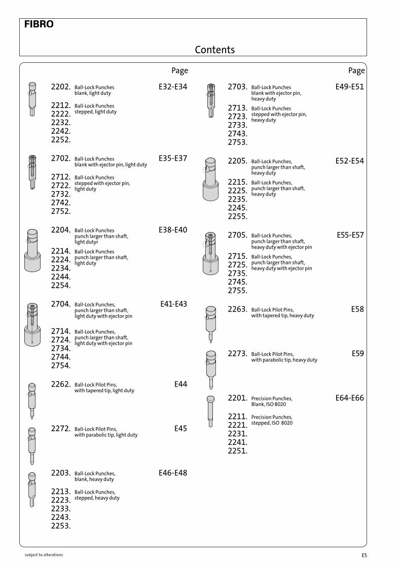
2202. Ball-Lock Punches blank, light duty
E32-E34
2212. 2222. 2232. 2242. 2252.
Ball-Lock Punches stepped, light duty
2702. Ball-Lock Punches blank with ejector pin, light duty
E35-E37
2712. 2722. 2732. 2742. 2752.
Ball-Lock Punches stepped with ejector pin, light duty
2204. Ball-Lock Punches punch larger than shaft, light dutyr
E38-E40
2214. 2224. 2234. 2244. 2254.
Ball-Lock Punches punch larger than shaft, light duty
2704.
Ball-Lock Punches, punch larger than shaft, light duty with ejector pin
E41-E43
2714. 2724. 2734. 2744. 2754.
Ball-Lock Punches, punch larger than shaft, light duty with ejector pin
2262.
Ball-Lock Pilot Pins, with tapered tip, light duty
E44
2272.
Ball-Lock Pilot Pins, with parabolic tip, light duty
E45
2203. Ball-Lock Punches, blank, heavy duty
E46-E48
2213. 2223. 2233. 2243. 2253.
Ball-Lock Punches, stepped, heavy duty
Page
2703. Ball-Lock Punches blank with ejector pin, heavy duty
E49-E51
2713. 2723. 2733. 2743. 2753.
Ball-Lock Punches stepped with ejector pin, heavy duty
2205. Ball-Lock Punches, punch larger than shaft, heavy duty
E52-E54
2215. 2225. 2235. 2245. 2255.
Ball-Lock Punches, punch larger than shaft, heavy duty
2705. Ball-Lock Punches, punch larger than shaft, heavy duty with ejector pin
E55-E57
2715. 2725. 2735. 2745. 2755.
Ball-Lock Punches, punch larger than shaft, heavy duty with ejector pin
2263.
Ball-Lock Pilot Pins, with tapered tip, heavy duty
E58
2273.
Ball-Lock Pilot Pins, with parabolic tip, heavy duty
E59
2201. Precision Punches, Blank, ISO 8020
E64-E66
2211. 2221. 2231. 2241. 2251.
Precision Punches, stepped, ISO 8020
Contents

subject to alterationsE6
Page
2701. Precision Punches, blanc, with ejector pin, ISO 8020
E67-E69
2711. 2721. 2731. 2741. 2751.
Precision Punches, stepped, with ejector pin, ISO 8020
2261.
Pilot Pins with tapered tip, ISO 8020
E70
2271.
Pilot Pins with parabolic tip, ISO 8020
E71
2276.
Pilot Units to Daimler Standard
E72
2606. 2616. 2626. 2636. 2646. 2656.
Precision Matrixes without shoulder, cylindrical ISO 8977
E77-E81
2607. 2617. 2627. 2637. 2647. 2657.
Precision Matrixes with shoulder, cylindrical, ISO 8977
E83-E87
2605. 2615. 2625. 2635. 2645. 2655.
Matrixes without shoulder, automotive standard
E88-E90
262. Precision Guide Bushes for Punches DIN 9845, Shape C
E92
2621. Precision Guide Bushes for Punches ISO 8978
E92
260. Precision Matrixes without collar DIN 9845, Shape A
E93
261. Precision Matrixes with collar, DIN 9845, Shape B
E93
Page
2602.
Precision Matrixes without collar, cylindrical
E94
2612.
Precision Matrixes with collar, cylindrical
E94
2601.
Precision Matrixes without collar, conical
E95
2611.
Precision Matrixes with collar, conical
E95
Standardised Special Shapes Punches/Precision Matrixes
E99-E101
2618.
Dynamic Strippers E104
2618.06. 2618.16. 2618.07. 2618.17.
Matrixes with or without shoulder for Dynamic Strippers
E105- E106
2664.05. 2664.06. 2664.07. 2664.10. 2664.08. 2664.09.
Triangle Precision Retainers for Ball-Lock Punches, light duty/heavy duty
E108- E110
Accessories for Precision Retainers, triangular, for Ball-Lock Punches
E111
2661.07. 2661.08.
Square Precision Retainers for Ball-Lock Punches, light duty
E112
2662.05.
Rectangular Precision Retainers for Ball-Lock Punches, light duty
E113
Contents
subject to alterations E7
Page
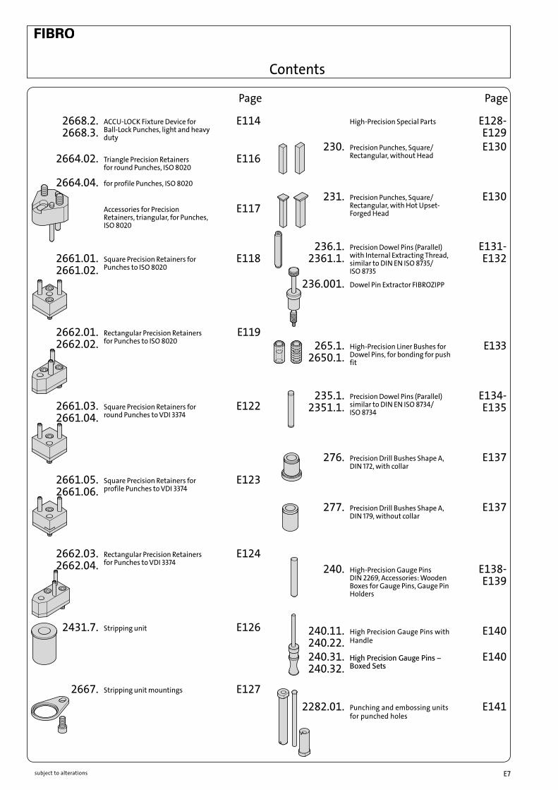
2668.2. 2668.3.
ACCU-LOCK Fixture Device for Ball-Lock Punches, light and heavy duty
E114
2664.02.
2664.04.
Triangle Precision Retainers for round Punches, ISO 8020 for profile Punches, ISO 8020
E116
Accessories for Precision Retainers, triangular, for Punches, ISO 8020
E117
2661.01. 2661.02.
Square Precision Retainers for Punches to ISO 8020
E118
2662.01. 2662.02.
Rectangular Precision Retainers for Punches to ISO 8020
E119
2661.03. 2661.04.
Square Precision Retainers for round Punches to VDI 3374
E122
2661.05. 2661.06.
Square Precision Retainers for profile Punches to VDI 3374
E123
2662.03. 2662.04.
Rectangular Precision Retainers for Punches to VDI 3374
E124
2431.7.
Stripping unit E126
2667.
Stripping unit mountings E127
Page
High-Precision Special Parts E128- E129
230.
Precision Punches, Square/Rectangular, without Head
E130
231.
Precision Punches, Square/Rectangular, with Hot Upset-Forged Head
E130
236.1. 2361.1.
Precision Dowel Pins (Parallel) with Internal Extracting Thread, similar to DIN EN ISO 8735/ ISO 8735
E131- E132
236.001.
Dowel Pin Extractor FIBROZIPP
265.1.2650.1.
High-Precision Liner Bushes for Dowel Pins, for bonding for push fit
E133
235.1. 2351.1.
Precision Dowel Pins (Parallel) similar to DIN EN ISO 8734/ ISO 8734
E134- E135
276.
Precision Drill Bushes Shape A, DIN 172, with collar
E137
277.
Precision Drill Bushes Shape A, DIN 179, without collar
E137
240.
High-Precision Gauge Pins DIN 2269, Accessories: Wooden Boxes for Gauge Pins, Gauge Pin Holders
E138- E139
240.11. 240.22.
High Precision Gauge Pins with Handle
E140
240.31. 240.32.
High Precision Gauge Pins – Boxed Sets
E140
2282.01.
Punching and embossing units for punched holes
E141
Contents

subject to alterationsE8

subject to alterations E9
Comparative Graphs
Compressive Strength (0,2% Proof Stress)
Flexural Strength
HV 30 - Hardness

E10 subject to alterations
FIBRO Punches and Matrixes – Description of Materials
WS = Alloy Tool Steel Material No 1.2210, 1.2516, 1.2842 or similar.Characteristics: Hard and tough tool steel, medium wear resistance.Application Field: Piercing/blanking dies for mild steel, low carbon steels, non-ferrous metals, plastics, paper. WS = material code number = “1” e.g. Order No = 239.1. ...
HWS = High Carbon – High Chrome Tool Steel (12% Cr) Material No 1.2436, 1.2379 or similar.Characteristics: High resistance to wear.Application Field: Piercing/blanking dies of all types, trim dies, for all carbon steels, alloy steels, non-ferrous metals, plastics, paper. HWS = material code number = “2” e.g. Order No = 260.2. ...
HSS = High Speed Steel Material No 1.3343 or similar.Characteristics: High wear resistance; high tempering curve permits certain surface treatments.Application Field: Piercing/blanking dies of all types – for tough materials e.g. spring steel, lamination steels, and abrasive papers as well as plastics. HSS = material code number = “3” e.g. Order No = 220.3. ...
ASP 23 = High Speed Steel on Powder-Metallurgic Basis ASP 2023 Characteristics: High wear resistance – greater toughness due to excellent homogenity.
Application Field: Same as HSS. ASP 23 ASP 2023 = material code number = “6” e.g. Order No = 223.6. ...
HST = High Speed Steel, NitridedCharacteristics: High wear resistance – reduced galling tendency on account of nitrides infused into top layer of material.Application Field: Piercing/blanking dies of all types – for very hard and abrasive materials. HST = material code number = “4” e.g. Order No = 223.4. ...
FT = Ferro-Tic (Ferro Titanit)Characteristics: Between those of HSS and hard metals (tungsten carbides); machinable in the supplied state – hardness conferred by heat treatment.Application Field: Fine blanking and progression/lamination dies for large quantities of parts from abrasive, hard materials, also silicon steels and stainless steels. FT special manufacture – on request –

E11subject to alterations
FIBRO Punches and Matrixes – Description of Materials
HZ = Hard-coated Tooling Components for High-Performance HZC Composite Vapour Deposition (CVD) TIC-TIN CoatingCarrier Materials: HSS Material No 1.3207 and 1.3343 etc. HCHC Material No 1.2379 and 1.2436 etc.Properties: The titanium carbide substrate provides a pressure-resistant bond with the carrier metal, while the outer layer of titanium nitride offers the well-known advantages of optimum tribologic behaviour in contact with the stamping stock. By virtue of its outstanding wear resistance, the TIN-layer largely eliminates seizing and cold welding problems in stamping. Surface Hardness: approx. 3500 HV 0,05 Coating Thickness: 5 to 8 μm approx.Applications: All tooling components subject to high demands on wear resistance and performance, especially punches in progression/combination tools, as well as cold extrusion punches etc. Owing to distorsion problems, TIC-TIN is not recommanded for parts with a length/thickness ratio than 20:1. TIC-TIN = material code number = “5” e. g. Order No = 223.5. ... HZN Titanium Nitride Coating TIN-PVD (physical vapour deposition).Carrier Material: HSS Material No 1.3207 and 1.3343 etc. HCHC Material No 1.2379 (HCHC-steels are of conditional suitability)Properties: The TIN-coating offers excellent frictional characteristics but its compressive strength remains inferior to TIC-TIN deposits. The TIN-deposition process can be applied to partial, selected areas of the tooling component. Surface Hardness: approx. 2300 HV 0,05 Coating Thickness: 2–4 mm < Ø 20 = 1,5 mm ± 20 %Applications: Tooling for thin stamping stock such as cold rolled spring steel, zinc-galvanized sheet and strip, copper-beryllium bronze, german silver, and solenoid lamination steels. Note that the ratio stock thickness to punch point diameter should not exceed 1:3. TIN = material code number = “0” e. g. Order No = 223.0. ...
HM = Tungsten CarbideCharacteristics: Hard-sintered carbide on WC-basis and of recognized properties; produced by powder-metallurgic processes, FIBRO’s exclusively used HIP-densified carbide exhibits much enhanced flexural strength and reduced residual porosity.Application Field: Die components for highest performance and very large stamping volumes – for altogether ultimate demands on tool life. HM = material code number = “9” e. g. Order No = 270.9. ...
NWA = Hot-Work Tool Steel – Suitable for Nitriding Material No 1.2344 or similar.Characteristics: Chrome-Molybdenum-Vanadium hot working die steel; core strength: L 1400 N/mm2; temperature resistant up to 650°C; surface hardness (nitrided) ^ 950 HV 0,3.Application Field: Ejector pins for pressure diecasting, injection- and compression moulding processes, and generally for work at elevated temperatures. NWA = material code number = “8” e. g. Order No = 237.8. ...
subject to alterationsE12
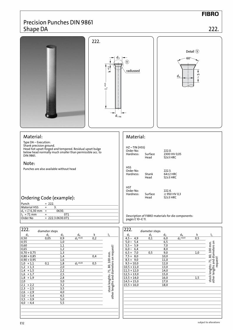
Precision Punches DIN 9861 Shape DA 222.
222.
222. d1 d1 d2 d4 k l10,50 0,05 0,9 d1+0,02 0,20,55 1,00,60 1,10,65 1,20,70 + 0,75 1,30,80 + 0,85 1,4 0,40,90 + 0,95 1,61,0 + 1,1 0,1 1,8 d1+0,03 0,51,2 + 1,3 2,01,4 + 1,5 2,21,6 + 1,7 2,51,8 + 1,9 2,82,0 3,02,1 + 2,2 3,22,3 – 2,5 3,52,6 – 2,9 4,03,0 – 3,4 4,53,5 – 3,9 5,04,0 – 4,4 5,5
diameter steps
stoc
k le
nght
s: 7
1, 8
0, 1
00 m
m.
othe
r len
gths
and
dia
met
ers o
n re
ques
t!
222. d1 d1 d2 d4 k l1 4,5 – 4,9 0,1 6,0 d1+0,03 0,5 5,0 – 5,4 6,5 5,5 – 5,9 7,0 6,0 – 6,4 8,0 6,5 + 7,0 0,5 9,0 1,0 7,5 + 8,0 10,0 8,5 + 9,0 11,0 9,5 + 10,0 12,010,5 + 11,0 13,011,5 + 12,0 14,012,5 + 13,0 15,013,5 + 14,0 16,0 1,514,5 + 15,0 17,015,5 + 16,0 18,0
stoc
k le
nght
s: 7
1, 8
0, 1
00 m
m.
othe
r len
gths
and
dia
met
ers o
n re
ques
t!
Ordering Code (example):Punch = 222.Material HSS = 222.3.d1 = [ 6,30 mm = 222.3.0630.l1 = 71 mm = 222.3.0630.071Order No = 222.3.0630.071
diameter steps
Material:Type DA – Execution:Shank precision ground.Head hot upset-forged and tempered. Residual upset bulgebelow head normally much smaller than permissible acc. toDIN 9861.
Note:Punches are also available without head
Material:
HZ – TIN (HSS) Order No: 222.0. Hardness: Surface 2300 HV 0,05 Head 52±3 HRC
HSS Order No: 222.3. Hardness: Shank 64±2 HRC Head 52±3 HRC
HST Order No: 222.4. Hardness: Surface ^ 950 HV 0,3 Head 52±3 HRC
Description of FIBRO materials for die components: pages E 10–E 11.

subject to alterations E13
d1 d1 d2 k l10,50 0,05 0,9 0,20,55 1,00,60 1,10,65 1,20,70 +0,75 1,30,80 +0,85 1,4 0,40,90 +0,95 1,61,0 +1,1 0,1 1,8 0,51,2 +1,3 2,01,4 +1,5 2,21,6 +1,7 2,51,8 +1,9 2,82,0 3,02,1 +2,2 3,22,3 –2,5 3,52,6 –2,9 4,03,0 –3,4 4,53,5 –3,9 5,04,0 –4,4 5,54,5 –4,9 0,1 6,05,0 –5,4 6,55,5 –5,9 7,0
Precision Punches DIN 9861 223. Shape D/ISO 6752
223.
Material:HSSOrder No: 223.3.Hardness: Shank 64±2 HRC Head 52±3 HRCHSTOrder No: 223.4.Hardness: Surface ^950 HV 0,3 Head 52±3 HRCHZ – TIN (HSS)Order No: 223.0.Hardness: Surface 2300 HV 0,05 Head 52±3 HRCASP 23–ASP 2023Order No: 223.6.Hardness: Shank 64±2 HRC Head 52±3 HRC
Type D – Execution:Head hot upset-forged and tempered. Shank and head subsequently precision plunge-ground for perfect concentricity and full interchangeability with replacement punches.
223. diameter steps
stoc
k le
nght
s: 7
1, 8
0, 1
00 m
m.
othe
r len
gths
and
dia
met
ers o
n re
ques
t!
223. d1 h6 d1 d2 k l1 6,0 – 6,4 0,1 8,0 0,5 6,5 + 7,0 0,5 9,0 1,0 7,5 + 8,0 10,0 8,5 + 9,0 11,0 9,5 +10,0 12,010,5 +11,0 13,011,5 +12,0 14,012,5 +13,0 15,013,5 +14,0 16,0 1,514,5 +15,0 17,015,5 +16,0 18,016,5 +17,0 19,017,5 +18,0 20,018,5 +19,0 21,019,5 +20,0 22,0
stoc
k le
nght
s: 7
1, 8
0, 1
00 m
m.
othe
r len
gths
and
dia
met
ers o
n re
ques
t!
Ordering Code (example):Punch = 223.Material HSS = 223.3.d1 = [ 16,5 mm = 223.3.1650.l1 = 80 mm = 223.3.1650.080Order No = 223.3.1650.080
diameter steps
Description of FIBRO materials for die components: pages E 10– E 11.

subject to alterationsE14
Precision Punches DIN 9861 224. Shape CA+C 225.
224. ShapeCA 225. Shape C
224. diameter steps d1 d1 d2 d3 d4 l10,1– 0,45 0,05 3 2 d3+0,03
0,500,550,600,650,70 + 0,750,80 + 0,850,90 + 0,951,00 – 1,101,15 – 1,301,35 – 1,501,55 – 1,70 4,5 31,75 – 1,901,95 – 2,002,05 – 2,202,25 – 2,502,55 – 2,95
stoc
k le
ngth
s: 7
1 m
m.
othe
r len
gths
and
dia
met
ers
on re
ques
t.
225. diameter steps d1 d1 d2 d3 l10,1– 0,45 0,05 3 20,500,550,600,650,70 + 0,750,80 + 0,850,90 + 0,951,00 – 1,101,15 – 1,301,35 – 1,501,55 – 1,70 4,5 31,75 – 1,901,95 – 2,002,05 – 2,202,25 – 2,502,55 – 2,95
stoc
k le
ngth
s: 7
1 m
m.
othe
r len
gths
and
dia
met
ers
on re
ques
t.
Ordering Code (example):Punch C = 225.Material HSS = 225.3.d1 = ∅ 2,30 mm = 225.3.0230.l1 = 71 mm = 225.3.0230.071Order No = 225.3.0230.071
Material:HZ – TIN (HSS) Order No: Form CA = 224.0. Form C = 225.0. Hardness: Surface 2300 HV 0,05 Head 52±3 HRCHSS Order No: Form CA = 224.3. Form C = 225.3. Hardness: Shank 64±2 HRC Head 52±3 HRCHST Order No: Form C = 225.4. Hardness: Surface ^950 HV 0,3 Head 52±3 HRCASP 23–ASP 2023 Order No: Form C = 225.6. Hardness: Shank 64±2 HRC Head 52±3 HRC
Executions:Shape CAShank precision ground, head subsequently hot upset-forged and tempered; residual upset-buge below head normally much smaller than permissible acc. to DIN 9861.Shape CHead hot upset-forged and tempered. Shank and head subsequently precision plunge-gorund for perfect concentricity and full interchangeability with replacement punches.
Description of FIBRO materials for die components: pages E 10– E 11.

subject to alterations E15
Precision Punches 274. Similar to DIN 9861 275. Shape CA+C
274. Shape CA 275. Shape C
Material:HZ – TIN (HSS) Order No: Form CA = 274.0. Form C = 275.0. Hardness: Surface 2300 HV 0,05 Head 52±3 HRCHSS Order No: Form CA = 274.3. Form C = 275.3. Hardness: Shank 64±2 HRC Head 52±3 HRCHST Order No: Form CA = 274.4. Form C = 275.4. Hardness: Surface ^950 HV 0,3 Head 52±3 HRCASP 23–ASP 2023 Order No: Form C = 275.6. Hardness: Shank 64±2 HRC Head 52±3 HRC
Description of FIBRO materials for die components: pages E 10–E 11.
Execution:Shape CAShank precision ground, head subsequently hot upset-forged and tempered; residual upset-bulge below head normally much smaller than permissible acc. to DIN 9861.Shape CHead hot upset-forged and tempered. Shank and head subsequently precision plunge-ground for perfect concentricity and full interchangeability with replacement punches.
Description of Special Series 274. and 275.DIN 9861 restricts the range of stepped punches with conical head to shanks of 3 mm max. diameter and points of 2,95 mm max. diameter.Stepped punches of larger size are, however, quite popular owing to their rigidity and ability to sustain considerable stripping forces.In accommodation of this demand we supply larger sizes which are ground from stock sizes of the 222.-and 223.-seriesPlease select from those ranges and complete your order in accordance with the example on the right.
Ordering Code (example):Punch CA = 274.Material HSS = 274.3.d3 = [ 8,0 mm = 274.3.0800.l1 = 71 mm = 274.3.0800.071.d1 = [ 6,4 mm = 274.3.0800.071.0640.l2 = 10 mm = 274.3.0800.071.0640.010Order No = 274.3.0800.071.0640.010

subject to alterationsE16
Stepped Quill Punches – Conical Head Head Type Quill Bush and Thrust Pin 232. 233. Ball Lock Type Quill Bush and Thrust Pin VDI 3374 234.
232.
232./233./234. diameter steps d1 d1 l l1 l2 l3 from 2,0 bis 5,0 0,1 63 48 29 29 71 57 37 37 80 65 46 46
Ordering Code (example):Stepped Quill Punch/Conical Head = 232.Material HSS23 = 3.d1 = [ 2,2 mm = 0220Order No = 232.3.0220
Execution:Heads of Quill Punches hot upset-forged; shank and head subsequently precision plunge-ground. O. D. of Quill Bushes precision ground. Thrust Pins are hardened, tempered and ground.
Material:Stepped Quill Punches – Conical Head VDI 3374: HSS Order No: 232.3. Hardness: Shank 62±2 HRC Head 45±5 HRCQuill Bushes O. No. 233. and 234. – VDI: Steel C 45 heat treated to 800 N/mm2 Order No: Shape A = 233.7., Shape B = 234.7.Thrust Pin: HWS Hardness: 62±2 HRC
Description of FIBRO materials for die components: pages E 10– E 11.
Ordering Code (example):Head Shape Quill bush + Thrust Pin = 233.Material C 4523 = 7.l1 = 48 mm = 048 Order No = 233.7.048
233.
Shape B234.Shape A233.
234.

subject to alterations E17
2281. Round Precision Punches 2291. with tapered heads 30°, Shape C+D
l1
d1 d2 d4 h k a±1° 100 1205,5 8,98 5,5 7,5 1 30 ● ●6 9,75 6 8 28 ● ●8 12,8 8 10 22,5 ● ●9 14,4 9 11 20 ● ●10 15,9 10 12 19 ● ●12 18,7 12 14 1,5 24 ●14 21,8 14 16 21 ●16 24,6 16 18 2 25 ●
2281. Shape D 2291. Shape C
Description of FIBRO materials for die components: pages E 10– E 11.
Ordering Code (example):Punch = 2281.Material HSS = 2281.3.d1 = 6 mm = 2281.3.0600.l1 = 100 mm = 2281.3.0600.100Order No = 2281.3.0600.100
l1
d3 d2 d4 h k a±1° 100 1205,5 8,98 5,5 7,5 1 30 ● ●6 9,75 6 8 28 ● ●8 12,8 8 10 22,5 ● ●9 14,4 9 11 20 ● ●10 15,9 10 12 19 ● ●12 18,7 12 14 1,5 24 ●14 21,8 14 16 21 ●16 24,6 16 18 2 25 ● d1 and l2 to customer’s specifications!
2291. Shape C
Execution: Shape C and DHead hot upset-forged and tempered.Shank and head subsequently precision plunge-ground forperfect concentricity and full interchangeability with replacementpunches.
Material: HSS Order No.: Shape D = 2281.3. Shape C = 2291.3. Hardness: Shank 58 + 2 HRC Head ≤ 50 HRC
2281. Shape D
Ordering Code (example):Punch = 2291.Material HSS = 2291.3.d3 = 10 mm = 2291.3.1000.l1 = 120 mm = 2291.3.1000.120.d1 = 6 mm = 2291.3.1000.120.0600.l2 = 15 mm = 2291.3.1000.120.0600.015Order No = 2291.3.1000.120.0600.015

subject to alterationsE18
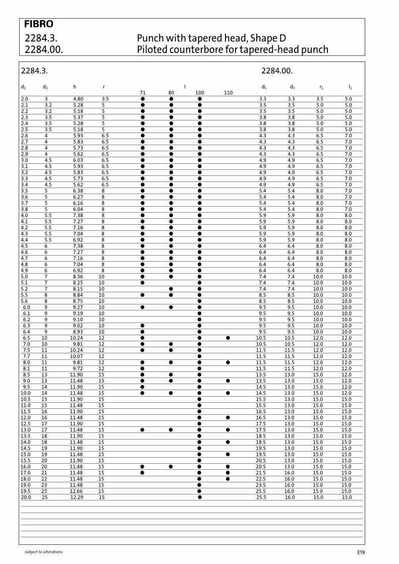
2284.3. 2284.00.
Punch with tapered head, Shape D Piloted counterbore for tapered-head punch
2284.3.
2284.00. 2284.00. Material: HSS Hardness: 62 - 66 HRC
Execution:hardened, tempered and ground
2284.3. Shape D
Material: HSS Order Code: 2284.3. Hardness: Shaft 62 - 66 HRC Head 45 - 55 HRC
Execution:Punch shaft fine ground. Punch head warm upset-forged and tempered.
For description of material and other materials see pages E10 - E11.
Ordering Code (example):Punch with tapered head = 2284.Material HSS = 2284.3.d1 = 20 mm = 2284.3.2000.l = 100 mm = 2284.3.2000.100Order Code = 2284.3.2000.100
Ordering Code (example):Piloted counterbore for tapered-head punch = 2284.00.d1 = 12.5 mm = 1250Order Code = 2284.00.1250
subject to alterations E19
2284.3. 2284.00.
d1 d2 h r l dS d3 r1 l1 71 80 100 1102.0 3 4.80 3.5 ● ● ● 3.3 3.3 3.5 5.02.1 3.2 5.28 5 ● ● ● 3.5 3.5 5.0 5.02.2 3.2 5.18 5 ● ● ● 3.5 3.5 5.0 5.02.3 3.5 5.37 5 ● ● ● 3.8 3.8 5.0 5.02.4 3.5 5.28 5 ● ● ● 3.8 3.8 5.0 5.02.5 3.5 5.18 5 ● ● ● 3.8 3.8 5.0 5.02.6 4 5.93 6.5 ● ● ● 4.3 4.3 6.5 7.02.7 4 5.83 6.5 ● ● ● 4.3 4.3 6.5 7.02.8 4 5.73 6.5 ● ● ● 4.3 4.3 6.5 7.02.9 4 5.62 6.5 ● ● ● 4.3 4.3 6.5 7.03.0 4.5 6.03 6.5 ● ● ● 4.9 4.9 6.5 7.03.1 4.5 5.93 6.5 ● ● ● 4.9 4.9 6.5 7.03.2 4.5 5.83 6.5 ● ● ● 4.9 4.9 6.5 7.03.3 4.5 5.73 6.5 ● ● ● 4.9 4.9 6.5 7.03.4 4.5 5.62 6.5 ● ● ● 4.9 4.9 6.5 7.03.5 5 6.38 8 ● ● ● 5.4 5.4 8.0 7.03.6 5 6.27 8 ● ● ● 5.4 5.4 8.0 7.03.7 5 6.16 8 ● ● ● 5.4 5.4 8.0 7.03.8 5 6.04 8 ● ● ● 5.4 5.4 8.0 7.04.0 5.5 7.38 8 ● ● ● 5.9 5.9 8.0 8.04.1 5.5 7.27 8 ● ● ● 5.9 5.9 8.0 8.04.2 5.5 7.16 8 ● ● ● 5.9 5.9 8.0 8.04.3 5.5 7.04 8 ● ● ● 5.9 5.9 8.0 8.04.4 5.5 6.92 8 ● ● ● 5.9 5.9 8.0 8.04.5 6 7.38 8 ● ● ● 6.4 6.4 8.0 8.04.6 6 7.27 8 ● ● ● 6.4 6.4 8.0 8.04.7 6 7.16 8 ● ● ● 6.4 6.4 8.0 8.04.8 6 7.04 8 ● ● ● 6.4 6.4 8.0 8.04.9 6 6.92 8 ● ● ● 6.4 6.4 8.0 8.05.0 7 8.36 10 ● ● ● 7.4 7.4 10.0 10.05.1 7 8.25 10 ● ● 7.4 7.4 10.0 10.05.2 7 8.15 10 ● ● 7.4 7.4 10.0 10.05.5 8 8.84 10 ● ● ● 8.5 8.5 10.0 10.05.6 8 8.75 10 ● 8.5 8.5 10.0 10.0 6.0 9 9.27 10 ● ● ● 9.5 9.5 10.0 10.0 6.1 9 9.19 10 ● 9.5 9.5 10.0 10.0 6.2 9 9.10 10 ● 9.5 9.5 10.0 10.0 6.3 9 9.02 10 ● ● 9.5 9.5 10.0 10.0 6.4 9 8.93 10 ● ● 9.5 9.5 10.0 10.0 6.5 10 10.24 12 ● ● ● 10.5 10.5 12.0 12.0 7.0 10 9.81 12 ● ● ● 10.5 10.5 12.0 12.0 7.5 11 10.24 12 ● ● ● 11.5 11.5 12.0 12.0 7.7 11 10.07 12 ● 11.5 11.5 12.0 12.0 8.0 11 9.81 12 ● ● ● ● 11.5 11.5 12.0 12.0 8.1 11 9.72 12 ● ● 11.5 11.5 12.0 12.0 8.5 13 11.90 15 ● ● ● 13.5 13.0 15.0 12.0 9.0 13 11.48 15 ● ● ● ● 13.5 13.0 15.0 12.0 9.5 14 11.90 15 ● ● 14.5 13.0 15.0 12.010.0 14 11.48 15 ● ● ● ● 14.5 13.0 15.0 12.010.5 15 11.90 15 ● 15.5 13.0 15.0 15.011.0 15 11.48 15 ● 15.5 13.0 15.0 15.011.5 16 11.90 15 ● 16.5 13.0 15.0 15.012.0 16 11.48 15 ● ● 16.5 13.0 15.0 15.012.5 17 11.90 15 ● 17.5 13.0 15.0 15.013.0 17 11.48 15 ● ● ● ● 17.5 13.0 15.0 15.013.5 18 11.90 15 ● 18.5 13.0 15.0 15.014.0 18 11.48 15 ● ● 18.5 13.0 15.0 15.014.5 19 11.90 15 ● 19.5 13.0 15.0 15.015.0 19 11.48 15 ● ● 19.5 13.0 15.0 15.015.5 20 11.90 15 ● 20.5 13.0 15.0 15.016.0 20 11.48 15 ● ● ● ● 20.5 13.0 15.0 15.017.0 21 11.48 15 ● ● ● 21.5 16.0 15.0 15.018.0 22 11.48 15 ● ● 22.5 16.0 15.0 15.019.0 23 11.48 15 ● 23.5 16.0 15.0 15.019.5 25 12.66 15 ● 25.5 16.0 15.0 15.020.0 25 12.29 15 ● 25.5 16.0 15.0 15.0
2284.3. 2284.00.
Punch with tapered head, Shape D Piloted counterbore for tapered-head punch

subject to alterationsE20
Assembly Guide Lines for Head Type Punches with Round Points
Description:Head type punches with round point (DIN 9844) are intended for floating assembly in the punch retainer. Radial guiding is to be provided by the stripper. This type of punch assembly eliminates alignment errors caused by distorted mounting of the die set and faulty press geometry. With punches held in this manner, a clear separation between transmission of perforation force and guiding is achieved. In order to facilitate assembly of punches of different diameters, the height of the heads is standardized to 4+0,2 mm (DIN 9844).
Guide Lines:(excerpts from DIN 9844, page 5)d1 max. = stock thicknessstripping force*, for d1 from 1 to 5 mm: approx. 20 % of piercing force ditto . . ., for d1 from 5 to 16 mm: approx. 10 % of piercing force*applicable to stock not exceeding 400 N/mm2 shear strengthPunch retainer: steel of at least 300 N/mm2 tensile strengthRetaining hole in punch retainer = 1,05 times d1 or d2 respectivelyClearance punch head/percussion plate = 0,02 mm.

subject to alterations E21
220. Precision Punches DIN 9844 221. Shape A+B
220. Shape A 221. Shape B
Material:HSS Order No: Shape A = 220.3. Shape B = 221.3. Hardness Shank 64±2 HRC Head 52±3 HRCHST Order No: Shape A = 220.4. Shape B = 221.4. Hardness Surface ^950 HV 0,3 Head 52±3 HRC
Execution:Head hot upset-forged.Shank and shoulder precision plunge-ground.
220. Shape A d1 d1 d3 r l1 2,0 – 2,2 0,1 3,6 0,2 2,3 – 2,5 4,0 2,6 – 2,8 4,5 0,3 2,9 – 3,2 5,0 3,3 – 3,5 6,0 3,6 – 4,0 7,0 4,1 – 4,5 8,0 0,5 4,6 – 5,0 8,5 5,1 – 5,4 9,0 5,5 – 5,9 9,5 6,0 – 6,4 10,0 6,5 + 7,0 0,5 10,8 0,7 7,5 + 8,0 12,0 8,5 + 9,0 13,0 9,5 +10,0 14,5 10,5 +11,0 16,0 1,0 11,5 –12,5 18,0 13,0 –14,5 20,0 15,0 –16,0 22,0
diameter steps
stoc
k le
ngth
s: 7
1, 9
0, 1
12 m
m;
othe
r len
gths
and
dia
met
ers o
n re
ques
t.
221. Shape B d1 d1 d2 d3 l2 r l1 0,1 – 0,45 0,05 2,0 3,6 7 0,2 0,5 – 1,9 1,95 – 2,4 2,5 4,0 2,5 – 3,1 0,1 3,2 5,0 0,3 3,2 – 3,9 4,0 7,0 4,0 – 4,9 5,0 8,5 0,5 5,0 – 6,2 6,3 10,0 6,3 – 7,9 8,0 12,0 16 0,7 8,0 – 9,9 10,0 14,5 10,0 –12,4 12,5 18,0 1,0 12,5 –15,9 16,0 22,0
leng
ths 7
1, 90
, 112
mm
ava
ilabl
e
at sh
ort n
otic
e; o
ther
leng
ths a
nd
diam
eter
s on
requ
est.
Ordering Code (example):Punch A = 220.Punch B = 221.Material HSS = 220.3.d1 = 7,0 mm = 220.3.0700.l1 = 71 mm = 220.3.0700.071Order No = 220.3.0700.071Order No = 221.3.0700.071
diameter steps
Description of FIBRO materials for die components: pages E 10– E 11.
subject to alterationsE22
subject to alterations E23
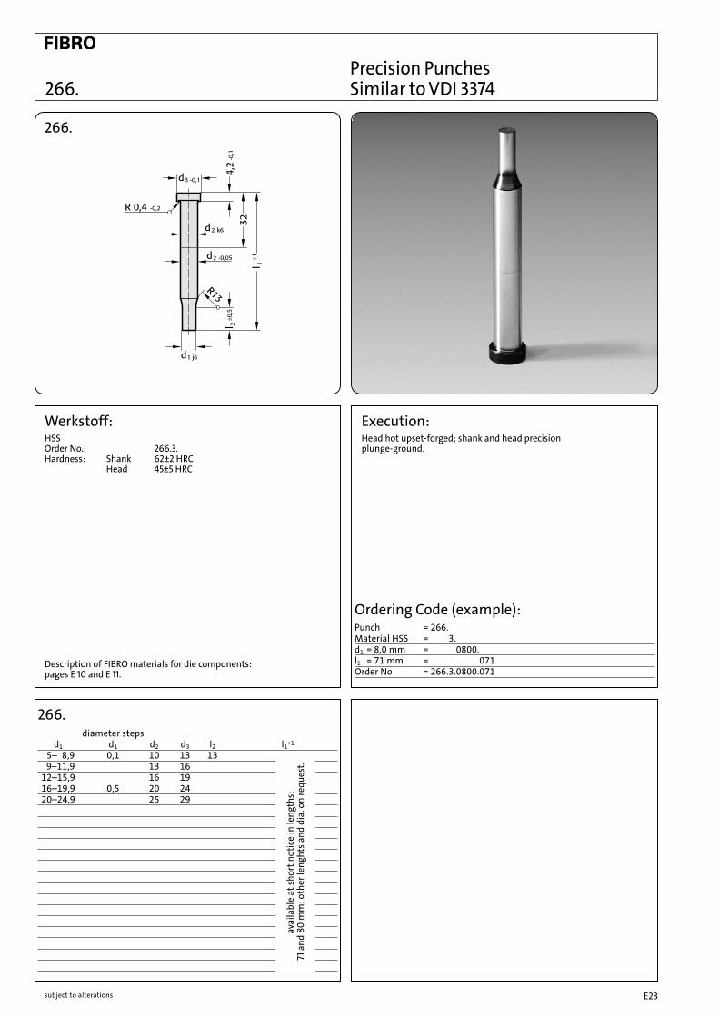
Precision Punches 266. Similar to VDI 3374
266.
Werkstoff:HSS Order No.: 266.3. Hardness: Shank 62±2 HRC Head 45±5 HRC
Description of FIBRO materials for die components: pages E 10 and E 11.
Execution:Head hot upset-forged; shank and head precisionplunge-ground.
266. d1 d1 d2 d3 l2 l1+1
5– 8,9 0,1 10 13 13 9–11,9 13 16 12–15,9 16 19 16–19,9 0,5 20 24 20–24,9 25 29
diameter steps
Ordering Code (example):Punch = 266.Material HSS = 266.3.d1 = 8,0 mm = 266.3.0800.l1 = 71 mm = 266.3.0800.071Order No = 266.3.0800.071
avai
labl
e at
shor
t not
ice
in le
ngth
s:
71 a
nd 8
0 m
m; o
ther
leng
hts a
nd d
ia. o
n re
ques
t.

subject to alterationsE24
267.
Precision Punches with Ejector Pin 267.
Execution:Head hot upset-forged.Shank and shoulder precision plunge-ground.
Ordering Code (example):Punch = 267.Material HSS = 267.3.d1 = 8,0 mm = 267.3.0800.l1 = 71 mm = 267.3.0800.071Order No = 267.3.0800.071
267. l1 d1-h6 d3 d4 k 60 71 80 90 M 5 8 0,5 5 • • M 3 6 9 0,8 • • • • 8 11 1,3 • • • • M 4 10 13 • • • • 13 16 1,6 • • • • M 5 16 19 2,4 6,4 • • • • M 6 20 23 • • • • 25 28 3,2 • • • •
Description of FIBRO materials for die components: pages E 10 and E 11.
Material:HSSOrder No: 267.3.Hardness: Shank 64±2 HRC Head 52±3 HRC

subject to alterations E25
Material:HSSOrder No: 268.3. (short point)Hardness: Shank 64±2 HRC Head 52±3 HRCHSSOrder No: 269.3. (long point)Hardness: Shank 64±2 HRC Head 52±3 HRC
268. 269.
Execution:Head hot upset-forged.Shank and shoulder precision plunge-ground.
Key flats parallel with longest size of shape, unless otherwisespecified.
Description of FIBRO materials for die components: pages E 10 and E 11.
268./269. 268. 269. l1 d1 d2 d3 d4 k l2 l2 60 71 80 90 a min. M 1,6 – 4,9 5 8 0,5 5 7 – • • 1,6 M 3 2,3 – 5,9 6 9 0,8 17,5 • • • • 2,3 3,5 – 7,9 8 11 1,3 13 25 • • • • 3,2 M 4 5,0 – 9,9 10 13 28 • • • • 4,8 6,0 – 12,9 13 16 1,6 • • • • M 5 8,0 – 15,9 16 19 2,4 6,4 • • • • 5,5 M 6 12,0 – 19,9 20 23 • • • • 16,0 – 24,9 25 28 3,2 • • • • 6,5
Ordering Code (example):Punch = 268.Material HSS = 268.3.d2 = 8,0 mm = 268.3.0800.l1 = 71 mm = 268.3.0800.071.Classified Point Shape 05 = 268.3.0800.071.05.d1 = 6,0 mm = 268.3.0800.071.05.0600Order No = 268.3.0800.071.05.0600
268. Precision Punches with Ejector Pin, 269. Stepped, Short/Long Point
Classified Point Shapes

subject to alterationsE26
Sintered Hard MetalHIP-Densified
The HIP Process (hot isostatic pressing) consists of a special densification treatment.
Applied after the sintering stage, this widely used process involves compacting, at very high temperature and pressure, of the carbidestructure. It yields an appreciable reduction in porosity, better strength properties and thus longer die life of press tool members.
As can be seen from the diagrams and tables, both compressive and flexural strength are improved.
For stamping die tooling, hard metal types of medium tungsten particle size, with a cobalt content of 9 to 12%, have been found succesful in a wide field of applications.
a) influence of crystallite size of hard metal phase (left: sintered only – right: sintered and HIP-treated)
b) influence of cobalt content (left: sintered only – right: sintered and HIP-treated)
3 1800 1200 1700
6 1650 1500 2300
9 1400 2000 2600
6 1600 2000 2600
9 1450 2350 2700
12 1300 2450 2900
15 1200 2700 2850
6 1400 1900 2250
8 1350 2300 2600
10 1200 2650 2850
Tungsten carbide- HV30-Hardness Flexural Strength particle Co N/mm2 size % befor after befor after
fine
medium
coarse
Flexural Strength and HV30-Hardness of Tungsten-Cobalt Carbides
with/without HIP-Treatment and in Dependance of Tungsten CarbideParticle Size and Cobalt Content.
nochanges
Tensile Strength of Tungsten – 6% Cobalt Carbide in the Sintered-Only versus HIP-Densified State, in Dependance of Cristallite Particle Size
Tensile Strength of Tungsten – Cobalt Carbide in the Sintered-Only versus HIP-Densified State, in Dependance of total Cobalt Content
subject to alterations E27
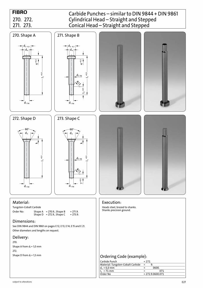
Carbide Punches – similar to DIN 9844 + DIN 9861 270. 272. Cylindrical Head – Straight and Stepped 271. 273. Conical Head – Straight and Stepped
270. Shape A 271. Shape B
272. Shape D 273. Shape C
Execution:Heads steel, brazed to shanks.Shanks precision ground.
Ordering Code (example):Carbide Punch = 272.Material: Tungsten-Cobalt Carbide = 272.9.d1 = 6,0 mm = 272.9.0600.l1 = 71 mm = 272.9.0600.071Order No = 272.9.0600.071
Material:Tungsten-Cobalt CarbideOrder No: Shape A = 270.9., Shape B = 271.9. Shape D = 272.9., Shape C = 273.9.
Dimensions:See DIN 9844 and DIN 9861 on pages E 12, E 13, E 14, E 15 and E 21.Other diameters and lengths on request.
Delivery: 270.Shape A from d1 = 1,0 mm272.Shape D from d1 = 1,5 mm

subject to alterationsE28

E29subject to alterations
Ball-Lock Punches

subject to alterations E30
subject to alterationsE31
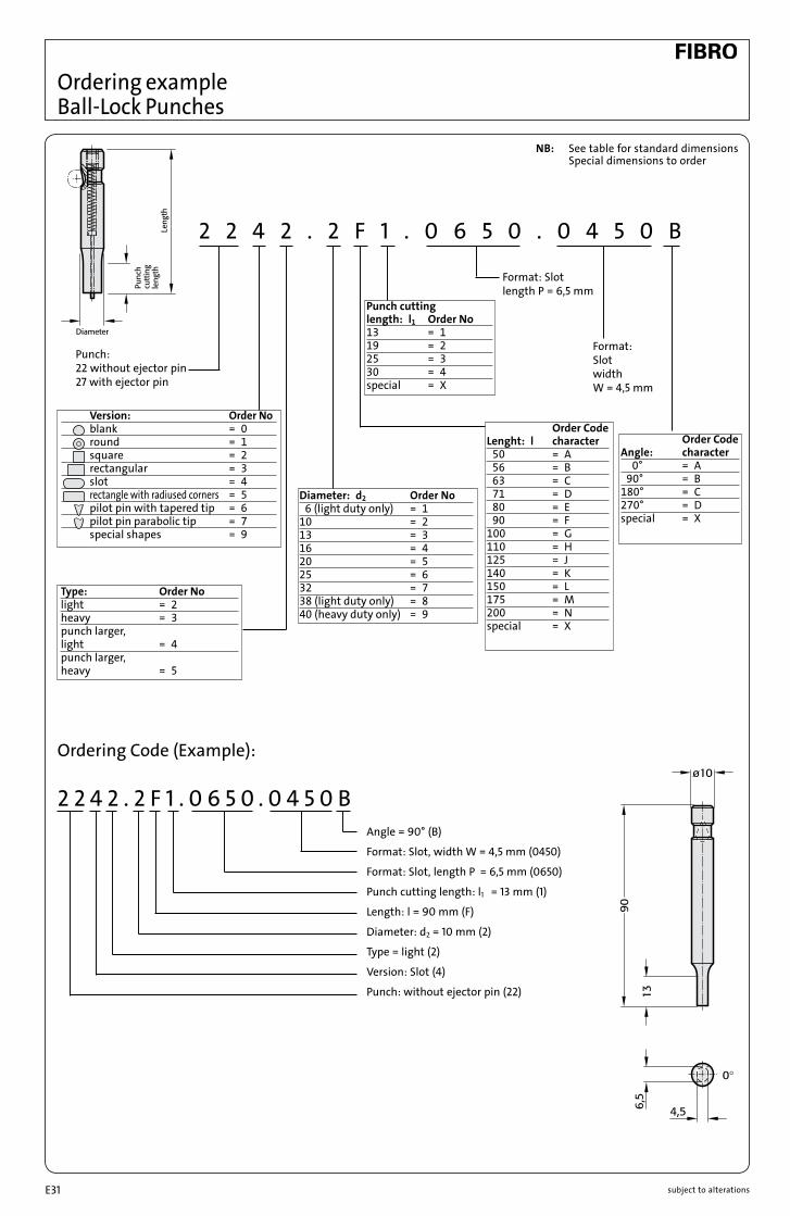
Ordering example Ball-Lock Punches
2 2 4 2 . 2 F 1 . 0 6 5 0 . 0 4 5 0 B
2 2 4 2 . 2 F 1 . 0 6 5 0 . 0 4 5 0 B
Punch: 22 without ejector pin 27 with ejector pin
Angle = 90° (B)
Format: Slot, width W = 4,5 mm (0450)
Format: Slot, length P = 6,5 mm (0650)
Punch cutting length: l1 = 13 mm (1)
Length: l = 90 mm (F)
Diameter: d2 = 10 mm (2)
Type = light (2)
Version: Slot (4)
Punch: without ejector pin (22)
Format: Slot length P = 6,5 mm
Format: Slot width W = 4,5 mm
Ordering Code (Example):
Version: Order No blank = 0 round = 1 square = 2 rectangular = 3 slot = 4 rectangle with radiused corners = 5 pilot pin with tapered tip = 6 pilot pin parabolic tip = 7 special shapes = 9
Type: Order Nolight = 2heavy = 3punch larger,light = 4punch larger,heavy = 5
Punch cutting length: l1 Order No13 = 119 = 225 = 330 = 4special = X
Diameter: d2 Order No 6 (light duty only) = 110 = 213 = 316 = 420 = 525 = 632 = 738 (light duty only) = 840 (heavy duty only) = 9
Order Code Lenght: l character 50 = A 56 = B 63 = C 71 = D 80 = E 90 = F100 = G110 = H125 = J140 = K150 = L175 = M200 = Nspecial = X
Order Code Angle: character 0° = A 90° = B180° = C270° = Dspecial = X
NB: See table for standard dimensions Special dimensions to order

E32 subject to alterations
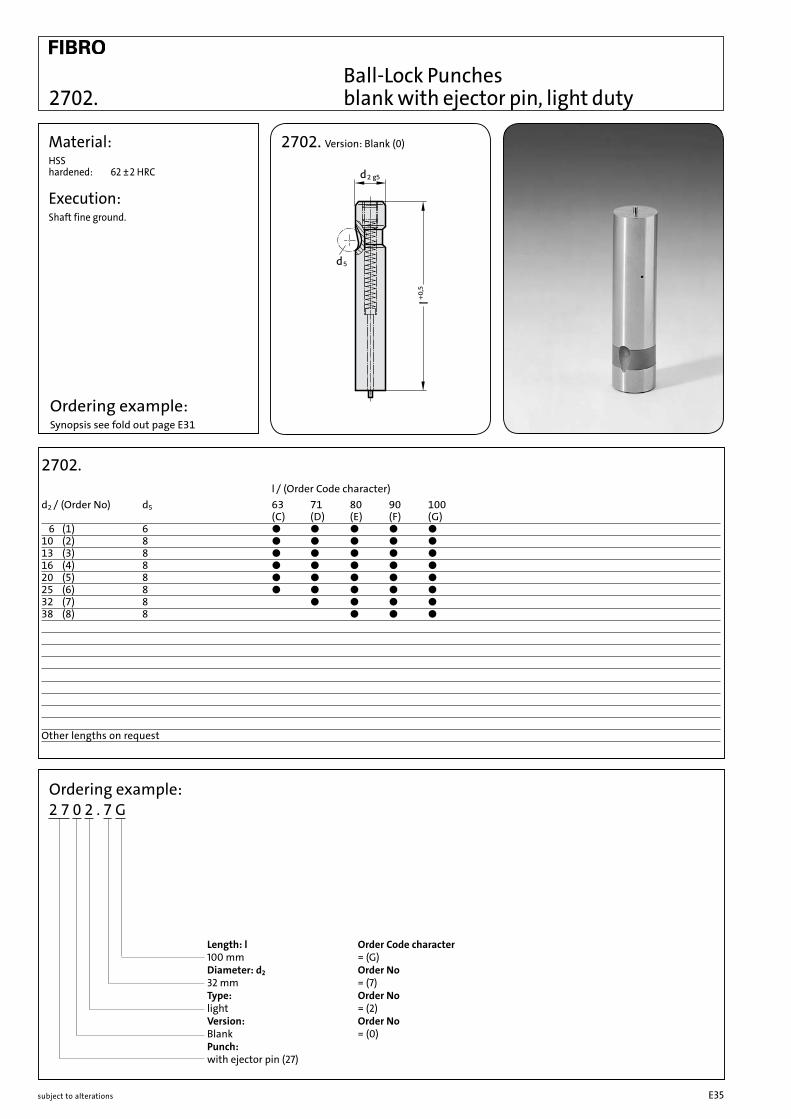
Ball-Lock Punches blank, light duty
Material:HSS hardened: 62 ± 2 HRC
Execution:Shaft fine ground.
2202. Version: blank (0)
2202.
Ordering Code (Example):2 2 0 2 . 7 G
Length: l Order Code character 100 mm = (G) Diameter: d2 Order No 32 mm = (7) Type: Order No light = (2) Version: Order No blank = (0) Punch: 22 without ejector pin
2202. l / (Order Code character )d2 / (Order No) d5 63 71 80 90 100 110 125 140 150 175 200 ( C ) ( D ) ( E ) ( F ) ( G ) ( H ) ( J ) ( K ) ( L ) ( M ) ( N ) 6 (1) 6 ● ● ● ● ●10 (2) 8 ● ● ● ● ● ● ●13 (3) 8 ● ● ● ● ● ● ● ● ● ●16 (4) 8 ● ● ● ● ● ● ● ● ● ●20 (5) 8 ● ● ● ● ● ● ● ● ● ●25 (6) 8 ● ● ● ● ● ● ● ● ● ● ●32 (7) 8 ● ● ● ● ● ● ● ● ● ●38 (8) 8 ● ● ● ● ● ● ● ● ●
Other lengths on request.
Ordering Code (Example): Synopsis see fold out page E31

Ball-Lock Punches stepped, light duty2212.
Material:HSS hardened: 62 ± 2 HRC
Execution:Shaft and punch diameter fine ground.
2212. Version: Round (1)
2212. l / (Order Code character) d2 / (Order No) d5 P l1 / (Order No) 63 71 80 90 100 ( C ) ( D ) ( E ) ( F ) ( G ) 6 (1) 6 1,6 - 5,9 13* (1) ● ● ● ● ●10 (2) 8 1,6 - 9,9 13* (1) 19* (2) ● ● ● ● ●13 (3) 8 5,0-12,9 13 (1) 19 (2) ● ● ● ● ●16 (4) 8 8,0-15,9 13 (1) 19 (2) 25 (3) ● ● ● ● ●20 (5) 8 12,0-19,9 13 (1) 19 (2) 25 (3) ● ● ● ● ●25 (6) 8 16,0-24,9 13 (1) 19 (2) 25 (3) ● ● ● ● ●32 (7) 8 24,0-31,9 13 (1) 19 (2) 25 (3) ● ● ● ●38 (8) 8 30,0-37,9 19 (2) 25 (3) 30 (4) ● ● ●
* I1 = 10 where P < 2,20
Other lengths on request
Ordering example: 2 2 1 2 . 7 G 2 . 2 4 5 0
Format: Round P = ø24,5 mm = (2450) Punch cutting length: l1 Order No 19 mm = (2) Length: l Order Code character 100 mm = (G) Diameter: d2 Order No 32 mm = (7) Typee: Order No light = (2) Version: Order No Round = (1) Punch: without ejector pin (22)
Ordering example:Synopsis see fold out page E31
subject to alterations E33

2222. 2232. 2242. 2252.
Material:HSS hardened: 62 ±2 HRC
Execution:Shaft and punch shape fine ground.
2222. Version: Square (2)
G = •(P–1.0)2+(W–1.0)2+1
G =•P2+W2
G = •2 3 P
G = P
* For other radius options, see standardised special shapes, pages E 100 – E 101
2232. Version: Rectangular (3)
2242. Version: Slot (4) 2252. Version: Rectangle with radiused corners (5)
Ball-Lock Punches, stepped, light duty
2222./ 2232./ 2242. / 2252. l/(Order Code character) d2 /(Order No) d5 Wmin. Gmax. l1 /(Order No) 63 71 80 90 100 ( C ) ( D ) ( E ) ( F ) ( G ) 6 (1) 6 1,6 5,9 13*(1) ● ● ● ● ●10 (2) 8 1,6 9,9 13*(1) 19*(2) ● ● ● ● ●13 (3) 8 4,5 12,9 13 (1) 19 (2) ● ● ● ● ●16 (4) 8 6,0 15,9 13 (1) 19 (2) 25 (3) ● ● ● ● ●20 (5) 8 8,0 19,9 13 (1) 19 (2) 25 (3) ● ● ● ● ●25 (6) 8 10,0 24,9 13 (1) 19 (2) 25 (3) ● ● ● ● ●32 (7) 8 12,5 31,9 13 (1) 19 (2) 25 (3) ● ● ● ●38 (8) 8 14,0 37,9 19 (2) 25 (3) 30 (4) ● ● ●
*l1 = 10 where P or W < 2,20
Other lengths on request
Ordering example: 2 2 4 2 . 2 F 1 . 0 6 5 0 . 0 4 5 0 B Angle Order Code character 90° = (B) Shape: Slot Width W W = 4,5 mm = (0450) Shape: Slot Length P P = 6,5 mm = (0650) Punch Cutting Length: l1 Order No 13 mm = (1) Length: l Order Code character 90 mm = (F) Diameter: d2 Order No 10 mm = (2) Type: Order No light = (2) Version: Order No Slot = (4) Punch: 22 without ejector pin Ordering example:
Synopsis see fold out page E31
3
3
subject to alterationsE34
Ball-Lock Punches blank with ejector pin, light duty
Material:HSS hardened: 62 ±2 HRC
Execution:Shaft fine ground.
2702.
Ordering example:2 7 0 2 . 7 G
Length: l Order Code character 100 mm = (G) Diameter: d2 Order No 32 mm = (7) Type: Order No light = (2) Version: Order No Blank = (0) Punch: with ejector pin (27)
2702. l / (Order Code character) d2 / (Order No) d5 63 71 80 90 100 ( C ) ( D ) ( E ) ( F ) ( G ) 6 (1) 6 ● ● ● ● ●10 (2) 8 ● ● ● ● ●13 (3) 8 ● ● ● ● ●16 (4) 8 ● ● ● ● ●20 (5) 8 ● ● ● ● ●25 (6) 8 ● ● ● ● ●32 (7) 8 ● ● ● ●38 (8) 8 ● ● ●
Other lengths on request
Ordering example: Synopsis see fold out page E31
2702. Version: Blank (0)
subject to alterations E35

Ball-Lock Punches stepped with ejector pin, light duty 2712.
Material:HSS hardened: 62 ±2 HRC
Execution:Shaft and punch diameter fine ground.
2712.
l / (Order Code character)d2 / (Order No) d5 P l1 / (Order No) 63 71 80 90 100 ( C ) ( D ) ( E ) ( F ) ( G ) 6 (1) 6 1,6 - 5,9 13* (1) ● ● ● ● ●10 (2) 8 1,6 - 9,9 13* (1) 19* (2) ● ● ● ● ●13 (3) 8 5,0-12,9 13 (1) 19 (2) ● ● ● ● ●16 (4) 8 8,0-15,9 13 (1) 19 (2) 25 (3) ● ● ● ● ●20 (5) 8 12,0-19,9 13 (1) 19 (2) 25 (3) ● ● ● ● ●25 (6) 8 16,0-24,9 13 (1) 19 (2) 25 (3) ● ● ● ● ●32 (7) 8 24,0-31,9 13 (1) 19 (2) 25 (3) ● ● ● ●38 (8) 8 30,0-37,9 19 (2) 25 (3) 30 (4) ● ● ●
* I1 = 10 where P < 2,20
Other lengths on request
Ordering example: 2 7 1 2 . 7 G 2 . 2 4 5 0
Format: Round P = ø24,5 mm = (2450) Punch cutting length: l1 Order No 19 mm = (2) Length: l Order Code character 100 mm = (G) Diameter: d2 Order No 32 mm = (7) Type: Order No light = (2) Version: Order No Round = (1) Punch: with ejector pin (27)
Ordering example:Synopsis see fold out page E31
2712. Version: Rund (1)
subject to alterationsE36

2722. 2732. 2742. 2752.
Ball-Lock Punches, stepped with ejector pin, light duty
Material:HSS hardened: 62 ±2 HRC
Execution:Shaft and punch shape fine ground.
2722./ 2732./ 2742. / 2752.
l /(Order Code character)d2 /(Order No) d5 Wmin. Gmax. l1 /(Order No) 63 71 80 90 100 ( C ) ( D ) ( E ) ( F ) ( G ) 6 (1) 6 1,6 5,9 13* (1) ● ● ● ● ●10 (2) 8 1,6 9,9 13* (1) 19* (2) ● ● ● ● ●13 (3) 8 4,5 12,9 13 (1) 19 (2) ● ● ● ● ●16 (4) 8 6,0 15,9 13 (1) 19 (2) 25 (3) ● ● ● ● ●20 (5) 8 8,0 19,9 13 (1) 19 (2) 25 (3) ● ● ● ● ●25 (6) 8 10,0 24,9 13 (1) 19 (2) 25 (3) ● ● ● ● ●32 (7) 8 12,5 31,9 13 (1) 19 (2) 25 (3) ● ● ● ●38 (8) 8 14,0 37,9 19 (2) 25 (3) 30 (4) ● ● ●
*l1 = 10 where P or W < 2,20
Other lengths on request
Ordering example: 2 7 4 2 . 2 F 1 . 0 6 5 0 . 0 4 5 0 B Angle Order Code character 90° = (B) Format: Slot, width W W = 4,5 mm = (0450) Format: Slot, length P P = 6,5 mm = (0650) Punch cutting length: l1 Order No 13 mm = (1) Length: l Order Code character 90 mm = (F) Diameter: d2 Order No 10 mm = (2) Type: Order No light = (2) Version: Order No Slot = (4) Punch: with ejector pin (27) Ordering example:
Synopsis see fold out page E31
2722. Version: Square (2)
G = •(P–1.0)2+(W–1.0)2+1
G =•P2+W2
G = •2 3 P
G = P
* For other radius options, see standardised special shapes, pages E 100 – E 101.
2732. Version: Rectangular (3)
2742. Version: Slot (4) 2752. Rectangle with radiused corners (5)
subject to alterations E37

Ball-Lock Punches punch larger than shaft, light duty
Material:HSS hardened: 62 ±2 HRC
Execution:Shaft and punch diameter fine ground.
2204.
2204. l / (Order Code character)d2 / (Order No) d5 P l1 / (Order No) 80 90 100 (E) ( F ) ( G )13 (3) 8 32,0 19 (2) 30 (4) ● ● ●16 (4) 8 38,0 19 (2) 30 (4) ● ● ●20 (5) 8 40,0 19 (2) 30 (4) ● ● ●25 (6) 8 44,0 19 (2) 30 (4) ● ● ●32 (7) 8 50,0 19 (2) 30 (4) ● ● ●
Other lengths on request
Ordering example: Synopsis see fold out page E31
2204. Version: Blank (0)
Ordering example:2 2 0 4 . 4 F 4 . 3 8 0 0
Version: Round P = ø38,0 mm = (3800) Punch cutting length l1 Order No 30 mm = (4) Length: l Order Code character 90 mm = (F) Diameter: d2 Order No 16 mm = (4) Type: Order No Punch larger, light = (4) Version: Order No Blank = (0) Punch: without ejector pin (22)
subject to alterationsE38

Ball-Lock Punches punch larger than shaft, light duty2214.
2214. Version: Round (1)
Ordering example: 2 2 1 4 . 7 G 2 . 3 2 1 0
Format: Round P = ø32,1 mm = (3210) Punch cutting length: l1 Order No 19 mm = (2) Length: l Order Code character 100 mm = (G) Diameter: d2 Order No 32 mm = (7) Type: Order No Punch larger, light = (4) Version: Order No Round = (1) Punch: without ejector pin (22)
2214.
l / (Order Code character) d2 / (Order No) d5 P l1 / (Order No) 80 90 100 (E) ( F ) ( G )13 (3) 8 13,1-32,0 19 (2) 30 (4) ● ● ●16 (4) 8 16,1-38,0 19 (2) 30 (4) ● ● ●20 (5) 8 20,1-40,0 19 (2) 30 (4) ● ● ●25 (6) 8 25,1-44,0 19 (2) 30 (4) ● ● ●32 (7) 8 32,1-50,0 19 (2) 30 (4) ● ● ●
Other lengths on request
Ordering example:Synopsis see fold out page E31
Material:HSS hardened: 62 ±2 HRC
Execution:Shaft and punch diameter fine ground.
subject to alterations E39

2224. 2234. 2244. 2254.
Material:HSS hardened: 62 ±2 HRC
Execution:Shaft and punch shape fine ground.
Ball-Lock Punches,, punch larger than shaft, light duty
Ordering example: 2 2 3 4 . 7 F 2 . 3 8 0 0 . 1 1 5 0 B Angle Order Code character 90° = (B) Format: Rectangular, width W W = 11,5 mm = (1150) Format: Rectangular, length P P = 38 mm = (3800) Punch cutting length: l1 Order No 19 mm = (2) Length: l Order Code character 90 mm = (F) Diameter: d2 Order No 32 mm = (7) Type: Order No Punch larger, light = (4) Version: Order No Rectangular = (3) Punch: without ejector pin (22)
2224. Version: Square (2)
G = •(P–1.0)2+(W–1.0)2+1
G =•P2+W2
G = •2 3 P
G = P
* For other radius options, see standardised special shapes, pages E 100 – E 101.
2234. Version: Rectangular (3)
2244. Version: Slot (4)
2254. Version: Rectangle with radiused corners (5)
2224./ 2234./ 2244. / 2254.
l /(Order Code character)d2 /(Order No) d5 Wmin. Gmax. l1 /(Order No) 80 90 100 ( E ) ( F ) ( G )13 (3) 8 5,0 32,0 19 (2) 30 (4) ● ● ●16 (4) 8 6,5 38,0 19 (2) 30 (4) ● ● ●20 (5) 8 8,0 40,0 19 (2) 30 (4) ● ● ●25 (6) 8 10,0 44,0 19 (2) 30 (4) ● ● ●32 (7) 8 11,5 50,0 19 (2) 30 (4) ● ● ●
Other lengths on request
Ordering example:Synopsis see fold out page E31
subject to alterationsE40

Ball-Lock Punches, punch larger than shaft, light duty with ejector pin
Material:HSS hardened: 62 ±2 HRC
Execution:Shaft and punch diameter fine ground.
2704.
2704.
l / (Order Code character)d2 / (Order No) d5 P l1 / (Order No) 80 90 100 (E) ( F ) ( G )13 (3) 8 32,0 19 (2) 30 (4) ● ● ●16 (4) 8 38,0 19 (2) 30 (4) ● ● ●20 (5) 8 40,0 19 (2) 30 (4) ● ● ●25 (6) 8 44,0 19 (2) 30 (4) ● ● ●32 (7) 8 50,0 19 (2) 30 (4) ● ● ●
Other lengths on request
Ordering example: Synopsis see fold out page E31
2704. Version: Blank (0)
Ordering example:2 7 0 4 . 4 F 4 . 3 8 0 0
Format: Round P = ø38,0 mm = (3800) Punch cutting length l1 Order No 30 mm = (4) Length: l Order Code character 90 mm = (F) Diameter: d2 Order No 16 mm = (4) Type: Order No Punch larger, light = (4) Version: Order No Blank = (0) Punch: with ejector pin (27)
subject to alterations E41
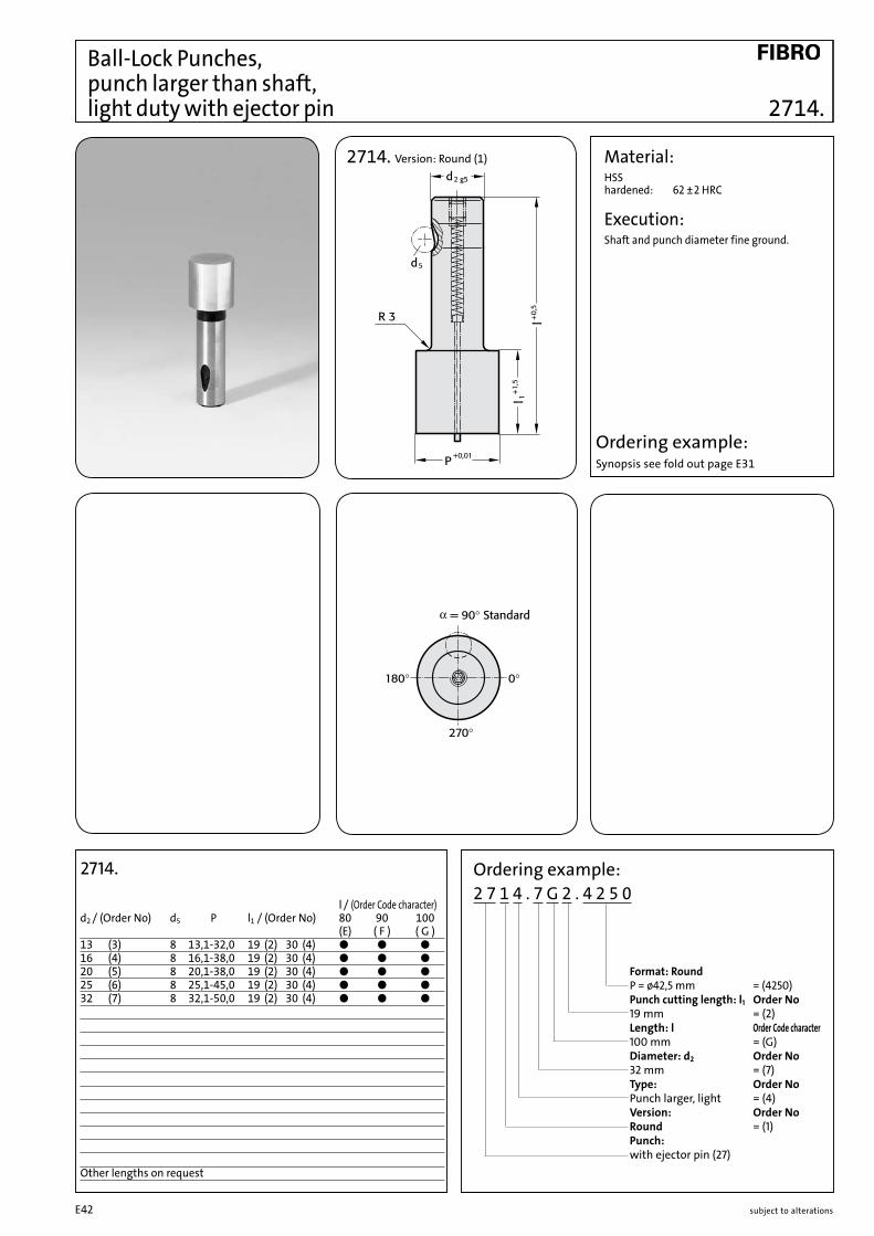
Ball-Lock Punches, punch larger than shaft, light duty with ejector pin 2714.
Ordering example: 2 7 1 4 . 7 G 2 . 4 2 5 0
Format: Round P = ø42,5 mm = (4250) Punch cutting length: l1 Order No 19 mm = (2) Length: l Order Code character 100 mm = (G) Diameter: d2 Order No 32 mm = (7) Type: Order No Punch larger, light = (4) Version: Order No Round = (1) Punch: with ejector pin (27)
2714.
l / (Order Code character) d2 / (Order No) d5 P l1 / (Order No) 80 90 100 (E) ( F ) ( G )13 (3) 8 13,1-32,0 19 (2) 30 (4) ● ● ●16 (4) 8 16,1-38,0 19 (2) 30 (4) ● ● ●20 (5) 8 20,1-38,0 19 (2) 30 (4) ● ● ●25 (6) 8 25,1-45,0 19 (2) 30 (4) ● ● ●32 (7) 8 32,1-50,0 19 (2) 30 (4) ● ● ●
Other lengths on request
Ordering example:Synopsis see fold out page E31
Material:HSS hardened: 62 ±2 HRC
Execution:Shaft and punch diameter fine ground.
2714. Version: Round (1)
subject to alterationsE42

2724. 2734. 2744. 2754.
Material:HSS hardened: 62 ±2 HRC
Execution:Shaft and punch shape fine ground.
Ball-Lock Punches, punch larger than shaft, light duty with ejector pin
Ordering example: 2 7 3 4 . 7 F 2 . 3 8 0 0 . 1 1 5 0 B Angle Order Code character 90° = (B) Format: Rectangular, width W W = 11,5 mm = (1150) Format: Rectangular, length P P = 38 mm = (3800) Punch cutting length: l1 Order No 19 mm = (2) Length: l Order Code character 90 mm = (F) Diameter: d2 Order No 32 mm = (7) Type: Order No Punch larger, light = (4) Version: Order No Rectangular = (3) Punch: with ejector pin (27)
2724./ 2734./ 2744. / 2754. l/(Order Code character)d2 /(Order No) d5 Wmin. Gmax. l1 /(Order No) 80 90 100 ( E ) ( F ) ( G )13 (3) 8 5,0 32,0 19 (2) 30 (4) ● ● ●16 (4) 8 6,5 38,0 19 (2) 30 (4) ● ● ●20 (5) 8 8,0 40,0 19 (2) 30 (4) ● ● ●25 (6) 8 10,0 44,0 19 (2) 30 (4) ● ● ●32 (7) 8 11,5 50,0 19 (2) 30 (4) ● ● ●
Other lengths on request
2724. Version: Square (2)
G = •(P–1.0)2+(W–1.0)2+1
G =•P2+W2
G = •2 3 P
G = P
2734. Version: Rectangular (3)
2744. Version: Slot (4)
2754. Version: Rectangle with radiused corners (5)
* For other radius options, see standardised special shapes, pages E 100 – E 101.
Ordering example:Synopsis see fold out page E31
subject to alterations E43

Ball-Lock Pilot Pins, with tapered tip, light duty 2262.
2262. Version: Pilot pin with tapered tip (6)
Ordering example:2 2 6 2 . 4 G 3 . 1 4 0 0 Format: Round P = ø 14 mm = (1400) Punch cutting length l1 : Order No 25 mm = (3) Length: l Order Code character 100 mm = (G) Diameter: d2 Order No 16 mm = (4) Type: Order No light = (2) Version: Order No Pilot pin with tapered tip = (6) Punch: without ejector pin (22)
Material:HSS hardened: 62 ±2 HRC
Execution:Shaft and pilot pin fine ground.
2262.
l / (Order Code character)d2 / (Order No) d5 P l1 / (Order No) N 71 80 90 100 110 125 140 150 ( D ) ( E ) ( F ) ( G ) ( H ) ( J ) ( K ) ( L )10 (2) 8 5,9- 9,9 19 (2) 8 ● ● ● ● ● 13 (3) 8 9,9-12,9 19 (2) 10 ● ● ● ● ● ● ●16 (4) 8 12,9-15,9 25 (3) 15 ● ● ● ● ● ● ● ●20 (5) 8 15,9-19,9 25 (3) 20 ● ● ● ● ● ● ● ●25 (6) 8 19,9-24,9 25 (3) 25 ● ● ● ● ● ● ● ●32 (7) 8 24,9-31,9 25 (3) 30 ● ● ● ● ● ● ●38 (8) 8 31,9-37,9 30 (4) 35 ● ● ● ● ● ● ●
Other lengths on request
Ordering example: Synopsis see fold out page E31
subject to alterationsE44

Ball-Lock Pilot Pins, with parabolic tip, light duty2272.
Ordering example:2 2 7 2 . 4 G 3 . 1 4 0 0 Format: Round P = ø 14 mm = (1400) Punch cutting length l1 : Order No 25 mm = (3) Length: l Order Code character 100 mm = (G) Diameter: d2 Order No 16 mm = (4) Type: Order No light = (2) Version: Order No Pilot pin parabolic tip = (7) Punch: without ejector pin (22)
2272.
l / (Order Code character)d2 / (Order No) d5 P l1 / (Order No) 50 56 63 71 80 90 100 ( A ) ( B ) ( C ) ( D ) ( E ) ( F ) ( G ) 6 (1) 6 2,9- 5,9 13 (1) ● ● ● ● ● ● ●10 (2) 8 5,9- 9,9 19 (2) ● ● ● ● ● ● ● 13 (3) 8 9,9-12,9 19 (2) ● ● ● ● ● ● ● 16 (4) 8 12,9-15,9 25 (3) ● ● ● ● ● 20 (5) 8 15,9-19,9 25 (3) ● ● ● ● ● 25 (6) 8 19,9-24,9 25 (3) ● ● ● ● ● 32 (7) 8 24,9-31,9 25 (3) ● ● ● ● 38 (8) 8 31,9-37,9 30 (4) ● ● ●
Other lengths on request
Material:HSS hardened: 62 ±2 HRC
Execution:Shaft and pilot pin fine ground.
„l“ length of pilot pin is without tipNote: The 2 mm length provides full guidance before the blanking punch contacts the sheet metal.
P N ≤10 mm 8 mm10,1 mm - 15 mm 12 mm > 15 mm 15 mm
2272. Version: Pilot pin parabolic tip (7)
Ordering example: Synopsis see fold out page E31
subject to alterations E45

Ball-Lock Punches, blank, heavy duty
Material:HSS hardened: 62 ±2 HRC
Execution:Shaft fine ground.
2203.
Ordering example:2 2 0 3 . 7 G
Length: l Order Code character 100 mm = (G) Diameter: d2 Order No 32 mm = (7) Type: Order No heavy = (3) Version: Order No Blank = (0) Punch: without ejector pin (22)
2203.
l / (Order Code character) d2 / (Order No) d5 63 71 80 90 100 110 125 140 150 175 200 ( C ) ( D ) ( E ) ( F ) ( G ) ( H ) ( J ) ( K ) ( L ) ( M ) ( N )10 (2) 10 ● ● ● ● ● ● ●13 (3) 12 ● ● ● ● ● ● ● ● ● ●16 (4) 12 ● ● ● ● ● ● ● ● ● ●20 (5) 12 ● ● ● ● ● ● ● ● ● ●25 (6) 12 ● ● ● ● ● ● ● ● ● ●32 (7) 12 ● ● ● ● ● ● ● ● ● ●40 (9) 12 ● ● ● ● ● ● ● ● ●
Other lengths on request
Ordering example: Synopsis see fold out page E31
2203. Version: Blank (0)
subject to alterationsE46
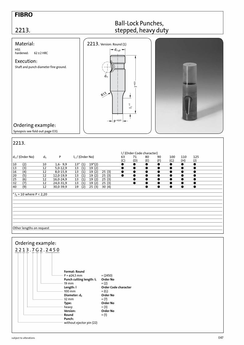
Ball-Lock Punches, stepped, heavy duty2213.
Material:HSS hardened: 62 ±2 HRC
Execution:Shaft and punch diameter fine ground.
2213.
l / (Order Code character) d2 / (Order No) d5 P l1 / (Order No) 63 71 80 90 100 110 125 ( C ) ( D ) ( E ) ( F ) ( G ) ( H ) ( J )10 (2) 10 1,6- 9,9 13* (1) 19* (2) ● ● ● ● ● ● ●13 (3) 12 5,0-12,9 13 (1) 19 (2) ● ● ● ● ● ● ●16 (4) 12 8,0-15,9 13 (1) 19 (2) 25 (3) ● ● ● ● ● ● ●20 (5) 12 12,0-19,9 13 (1) 19 (2) 25 (3) ● ● ● ● ● ● ●25 (6) 12 16,0-24,9 13 (1) 19 (2) 25 (3) ● ● ● ● ● ●32 (7) 12 24,0-31,9 13 (1) 19 (2) 25 (3) ● ● ● ● ● ●40 (9) 12 30,0-39,9 19 (2) 25 (3) 30 (4) ● ● ● ● ●
* I1 = 10 where P < 2,20
Other lengths on request
Ordering example: 2 2 1 3 . 7 G 2 . 2 4 5 0
Format: Round P = ø24,5 mm = (2450) Punch cutting length: l1 Order No 19 mm = (2) Length: l Order Code character 100 mm = (G) Diameter: d2 Order No 32 mm = (7) Type: Order No heavy = (3) Version: Order No Round = (1) Punch: without ejector pin (22)
Ordering example:Synopsis see fold out page E31
2213. Version: Round (1)
subject to alterations E47
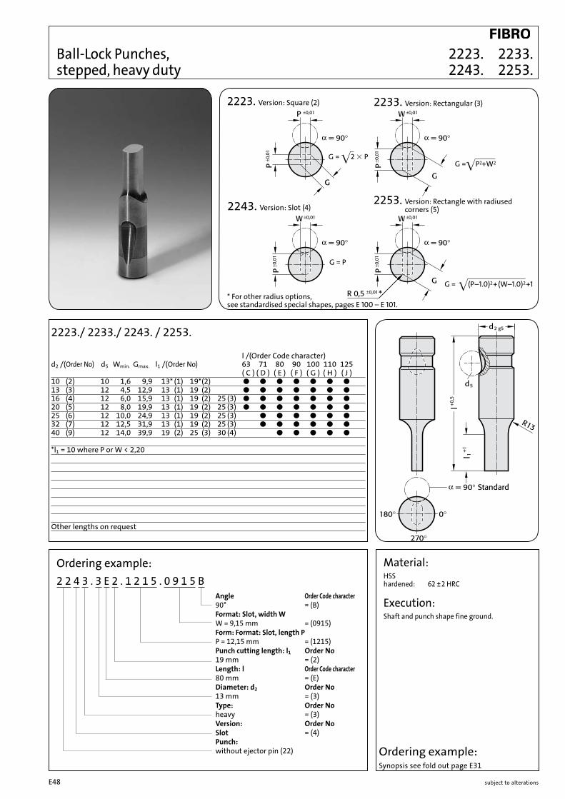
2223. 2233. 2243. 2253.
Material:HSS hardened: 62 ±2 HRC
Execution:Shaft and punch shape fine ground.
2223. Version: Square (2)
G = •(P–1.0)2+(W–1.0)2+1
G =•P2+W2G = •2 3 P
G = P
* For other radius options, see standardised special shapes, pages E 100 – E 101.
2233. Version: Rectangular (3)
2243. Version: Slot (4)2253. Version: Rectangle with radiused
corners (5)
Ball-Lock Punches, stepped, heavy duty
2223./ 2233./ 2243. / 2253.
l /(Order Code character) d2 /(Order No) d5 Wmin. Gmax. l1 /(Order No) 63 71 80 90 100 110 125 ( C ) ( D ) ( E ) ( F ) ( G ) ( H ) ( J )10 (2) 10 1,6 9,9 13* (1) 19* (2) ● ● ● ● ● ● ●13 (3) 12 4,5 12,9 13 (1) 19 (2) ● ● ● ● ● ● ●16 (4) 12 6,0 15,9 13 (1) 19 (2) 25 (3) ● ● ● ● ● ● ●20 (5) 12 8,0 19,9 13 (1) 19 (2) 25 (3) ● ● ● ● ● ● ●25 (6) 12 10,0 24,9 13 (1) 19 (2) 25 (3) ● ● ● ● ● ●32 (7) 12 12,5 31,9 13 (1) 19 (2) 25 (3) ● ● ● ● ● ●40 (9) 12 14,0 39,9 19 (2) 25 (3) 30 (4) ● ● ● ● ●
*l1 = 10 where P or W < 2,20
Other lengths on request
Ordering example: 2 2 4 3 . 3 E 2 . 1 2 1 5 . 0 9 1 5 B Angle Order Code character 90° = (B) Format: Slot, width W W = 9,15 mm = (0915) Form: Format: Slot, length P P = 12,15 mm = (1215) Punch cutting length: l1 Order No 19 mm = (2) Length: l Order Code character 80 mm = (E) Diameter: d2 Order No 13 mm = (3) Type: Order No heavy = (3) Version: Order No Slot = (4) Punch: without ejector pin (22) Ordering example:
Synopsis see fold out page E31
subject to alterationsE48

Ball-Lock Punches blank with ejector pin, heavy duty
Material:HSS hardened: 62 ±2 HRC
Execution:Shaft fine ground.
2703.
Ordering example:2 7 0 3 . 7 G
Length: l Order Code character 100 mm = (G) Diameter: d2 Order No 32 mm = (7) Type: Order No heavy = (3) Version: Order No Blank = (0) Punch: with ejector pin (27)
2703.
l / (Order Code character) d2 / (Order No) d5 63 71 80 90 100 110 125 ( C ) ( D ) ( E ) ( F ) ( G ) ( H ) ( J )10 (2) 10 ● ● ● ● ● 13 (3) 12 ● ● ● ● ● ● ●16 (4) 12 ● ● ● ● ● ● ●20 (5) 12 ● ● ● ● ● ● ●25 (6) 12 ● ● ● ● ● ●32 (7) 12 ● ● ● ● ● ●40 (9) 12 ● ● ● ● ●
Other lengths on request
Ordering example: Synopsis see fold out page E31
2703. Version: Blank (0)
subject to alterations E49

Ball-Lock Punches stepped with ejector pin, heavy duty 2713.
Material:HSS hardened: 62 ±2 HRC
Execution:Shaft and punch diameter fine ground.
2713.
l / (Order Code character) d2 / (Order No) d5 P l1 / (Order No) 63 71 80 90 100 110 125 ( C ) ( D ) ( E ) ( F ) ( G ) ( H ) ( J )10 (2) 10 1,6- 9,9 13* (1) 19* (2) ● ● ● ● ●13 (3) 12 5,0-12,9 13 (1) 19 (2) ● ● ● ● ● ● ●16 (4) 12 8,0-15,9 13 (1) 19 (2) 25 (3) ● ● ● ● ● ● ●20 (5) 12 12,0-19,9 13 (1) 19 (2) 25 (3) ● ● ● ● ● ● ●25 (6) 12 16,0-24,9 13 (1) 19 (2) 25 (3) ● ● ● ● ● ●32 (7) 12 24,0-31,9 13 (1) 19 (2) 25 (3) ● ● ● ● ● ●40 (9) 12 30,0-39,9 19 (2) 25 (3) 30 (4) ● ● ● ● ●
* I1 = 10 where P < 2,20
Other lengths on request
Ordering example: 2 7 1 3 . 3 C 1 . 0 5 5 0
Format: Round P = ø5,5 mm = (0550) Punch cutting length: l1 Order No 13 mm = (1) Length: l Order Code character 63 mm = (C) Diameter: d2 Order No 13 mm = (3) Type: Order No heavy = (3) Version: Order No Round = (1) Punch: with ejector pin (27)
Ordering example:Synopsis see fold out page E31
2713. Version: Round (1)
subject to alterationsE50

2723. 2733. 2743. 2753.
Material:HSS hardened: 62 ±2 HRC
Execution:Shaft and punch shape fine ground.
Ball-Lock Punches, stepped with ejector pin, heavy duty
2723./ 2733./ 2743. / 2753.
l /(Order Code character) d2 /(Order No) d5 Wmin. Gmax. l1 /(Order No) 63 71 80 90 100 110 125 ( C ) ( D ) ( E ) ( F ) ( G ) ( H ) ( J )10 (2) 10 1,6 9,9 13* (1) 19* (2) ● ● ● ● ●13 (3) 12 4,5 12,9 13 (1) 19 (2) ● ● ● ● ● ● ●16 (4) 12 6,0 15,9 13 (1) 19 (2) 25 (3) ● ● ● ● ● ● ●20 (5) 12 8,0 19,9 13 (1) 19 (2) 25 (3) ● ● ● ● ● ● ●25 (6) 12 10,0 24,9 13 (1) 19 (2) 25 (3) ● ● ● ● ● ●32 (7) 12 12,5 31,9 13 (1) 19 (2) 25 (3) ● ● ● ● ● ●40 (9) 12 14,0 39,9 19 (2) 25 (3) 30 (4) ● ● ● ● ●
*l1 = 10 where P or W < 2,20
Other lengths on request
Ordering example: 2 7 4 3 . 2 F 1 . 0 6 5 0 . 0 4 5 0 B Angle Order Code character 90° = (B) Format: Slot, width W W = 4,5 mm = (0450) Format: Slot, length P P = 6,5 mm = (0650) Punch cutting length: l1 Order No 13 mm = (1) Length: l Order Code character 90 mm = (F) Diameter: d2 Order No 10 mm = (2) Type: Order No heavy = (3) Version: Order No Slot = (4) Punch: with ejector pin (27) Ordering example:
Synopsis see fold out page E31
2723. Version: Square (2)
G = •(P–1.0)2+(W–1.0)2+1
G =•P2+W2
G = •2 3 P
G = P
* For other radius options, see standardised special shapes, pages E 100 – E 101.
2733. Version: Rectangular (3)
2743. Version: Slot (4)2753. Version: Rectangle with radiused
corners (5)
subject to alterations E51

Ball-Lock Punches, punch larger than shaft, heavy duty
Material:HSS hardened: 62 ±2 HRC
Execution:Shaft and punch diameter fine ground.
2205.
2205.
l / (Order Code character) d2 / (Order No) d5 P l1 / (Order No) 80 90 100 (E) ( F ) ( G )13 (3) 12 32,0 19 (2) 30 (4) ● ● ●16 (4) 12 38,0 19 (2) 30 (4) ● ● ●20 (5) 12 40,0 19 (2) 30 (4) ● ● ●25 (6) 12 44,0 19 (2) 30 (4) ● ● ●32 (7) 12 50,0 19 (2) 30 (4) ● ● ●40 (9) 12 56,0 19 (2) 30 (4) ● ● ●
Other lengths on request
Ordering example: Synopsis see fold out page E31
Ordering example:2 2 0 5 . 7 G 4 . 5 0 0 0
Format: Round P = ø50,0 mm = (5000) Punch cutting length l1 Order No 30 mm = (4) Length: l Order Code character 100 mm = (G) Diameter: d2 Order No 32 mm = (7) Type: Order No Punch larger, heavy = (5) Version: Order No Blank = (0) Punch: without ejector pin (22)
2205. Version: Blank (0)
subject to alterationsE52

Ball-Lock Punches, punch larger than shaft, heavy duty2215.
2215. Version: Round (1)
Ordering example: 2 2 1 5 . 7 G 2 . 3 2 1 0
Format: Round P = ø32,1 mm = (3210) Punch cutting length: l1 Order No 19 mm = (2) Length: l Order Code character 100 mm = (G) Diameter: d2 Order No 32 mm = (7) Type: Order No Punch larger, heavy = (5) Version: Order No Round = (1) Punch: without ejector pin (22)
2215.
l / (Order Code character) d2 / (Order No) d5 P l1 / (Order No) 80 90 100 (E) ( F ) ( G )13 (3) 12 13,1-32,0 19 (2) 30 (4) ● ● ●16 (4) 12 16,1-38,0 19 (2) 30 (4) ● ● ●20 (5) 12 20,1-40,0 19 (2) 30 (4) ● ● ●25 (6) 12 25,1-44,0 19 (2) 30 (4) ● ● ●32 (7) 12 32,1-50,0 19 (2) 30 (4) ● ● ●40 (9) 12 40,1-56,0 19 (2) 30 (4) ● ● ●
Other lengths on request
Ordering example:Synopsis see fold out page E31
Material:HSS hardened: 62 ±2 HRC
Execution:Shaft and punch diameter fine ground.
subject to alterations E53
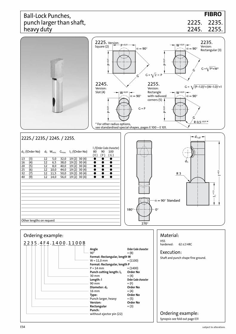
2225. 2235. 2245. 2255.
Material:HSS hardened: 62 ±2 HRC
Execution:Shaft and punch shape fine ground.
Ball-Lock Punches, punch larger than shaft, heavy duty
Ordering example: 2 2 3 5 . 4 F 4 . 1 4 0 0 . 1 1 0 0 B Angle Order Code character 90° = (B) Format: Rectangular, length W W = 11,0 mm = (1100) Format: Rectangular, length P P = 14 mm = (1400) Punch cutting length: l1 Order No 30 mm = (4) Length: l Order Code character 90 mm = (F) Diameter: d2 Order No 16 mm = (4) Type: Order No Punch larger, heavy = (5) Version: Order No Rectangular = (3) Punch: without ejector pin (22)
* For other radius options, see standardised special shapes, pages E 100 – E 101.
2225./ 2235./ 2245. / 2255.
l /(Order Code character) d2 /(Order No) d5 Wmin. Gmax. l1 /(Order No) 80 90 100 ( E ) ( F ) ( G )13 (3) 12 5,0 32,0 19 (2) 30 (4) ● ● ●16 (4) 12 6,5 38,0 19 (2) 30 (4) ● ● ●20 (5) 12 8,0 40,0 19 (2) 30 (4) ● ● ●25 (6) 12 10,0 44,0 19 (2) 30 (4) ● ● ●32 (7) 12 11,5 50,0 19 (2) 30 (4) ● ● ●40 (9) 12 14,0 56,0 19 (2) 30 (4) ● ● ●
Other lengths on request
2225. Version: Square (2)
G = •(P–1.0)2+(W–1.0)2+1
G =•P2+W2
G = •2 3 P
G = P
2235. Version: Rectangular (3)
2245. Version: Slot (4)
2255. Version: Rectangle with radiused corners (5)
Ordering example:Synopsis see fold out page E31
subject to alterationsE54

Ball-Lock Punches, punch larger than shaft, heavy duty with ejector pin
Material:HSS hardened: 62 ±2 HRC
Execution:Shaft and punch diameter fine ground.
2705.
2705.
l / (Order Code character) d2 /(Order No) d5 P l1 /(Order No) 80 90 100 (E) ( F ) ( G )13 (3) 12 32,0 19 (2) 30 (4) ● ● ●16 (4) 12 38,0 19 (2) 30 (4) ● ● ●20 (5) 12 40,0 19 (2) 30 (4) ● ● ●25 (6) 12 44,0 19 (2) 30 (4) ● ● ●32 (7) 12 50,0 19 (2) 30 (4) ● ● ●40 (9) 12 56,0 19 (2) 30 (4) ● ● ●
Other lengths on request
Ordering example: Synopsis see fold out page E31
Ordering example:2 7 0 5 . 7 G 4 . 5 0 0 0
Format: Round P = ø50,0 mm = (5000) Punch cutting length l1 Order No 30 mm = (4) Length: l Order Code character 100 mm = (G) Diameter: d2 Order No 32 mm = (7) Type: Order No Punch larger, heavy = (5) Version: Order No Blank = (0) Punch: with ejector pin (27)
2705. Version: Blank (0)
subject to alterations E55

Ball-Lock Punches, punch larger than shaft, heavy duty with ejector pin 2715.
Ordering example: 2 7 1 5 . 7 G 2 . 3 2 1 0
Format: Round P = ø32,1 mm = (3210) Punch cutting length: l1 Order No 19 mm = (2) Length: l Order Code character 100 mm = (G) Diameter: d2 Order No 32 mm = (7) Type: Order No Punch larger, heavy = (5) Version: Order No Round = (1) Punch: with ejector pin (27)
2715.
l / (Order Code character)d2 / (Order No) d5 P l1 / (Order No) 80 90 100 (E) ( F ) ( G )13 (3) 12 13,1-32,0 19 (2) 30 (4) ● ● ●16 (4) 12 16,1-38,0 19 (2) 30 (4) ● ● ●20 (5) 12 20,1-40,0 19 (2) 30 (4) ● ● ●25 (6) 12 25,1-44,0 19 (2) 30 (4) ● ● ●32 (7) 12 32,1-50,0 19 (2) 30 (4) ● ● ●40 (9) 12 40,1-56,0 19 (2) 30 (4) ● ● ●
Other lengths on request
Material:HSS hardened: 62 ±2 HRC
Execution:Shaft and punch diameter fine ground.
2715. Version: Round (1)
Ordering example:Synopsis see fold out page E31
subject to alterationsE56
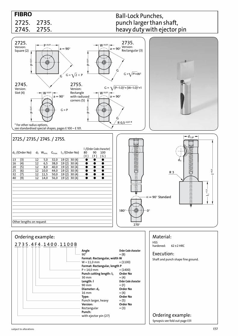
2725. 2735. 2745. 2755.
Material:HSS hardened: 62 ±2 HRC
Execution:Shaft and punch shape fine ground.
Ball-Lock Punches, punch larger than shaft, heavy duty with ejector pin
Ordering example: 2 7 3 5 . 4 F 4 . 1 4 0 0 . 1 1 0 0 B Angle Order Code character 90° = (B) Format: Rectangular, width W W = 11,0 mm = (1100) Format: Rectangular, length P P = 14,0 mm = (1400) Punch cutting length: l1 Order No 30 mm = (4) Length: l Order Code character 90 mm = (F) Diameter: d2 Order No 16 mm = (4) Type: Order No Punch larger, heavy = (5) Version: Order No Rectangular = (3) Punch: with ejector pin (27)
2725./ 2735./ 2745. / 2755.
l /(Order Code character) d2 /(Order No) d5 Wmin. Gmax. l1 /(Order No) 80 90 100 ( E ) ( F ) ( G )13 (3) 12 5,0 32,0 19 (2) 30 (4) ● ● ●16 (4) 12 6,5 38,0 19 (2) 30 (4) ● ● ●20 (5) 12 8,0 40,0 19 (2) 30 (4) ● ● ●25 (6) 12 10,0 44,0 19 (2) 30 (4) ● ● ●32 (7) 12 11,5 50,0 19 (2) 30 (4) ● ● ●40 (9) 12 14,0 56,0 19 (2) 30 (4) ● ● ●
Other lengths on request
2725. Version: Square (2)
G = •(P–1.0)2+(W–1.0)2+1
G =•P2+W2G = •2 3 P
G = P
2735. Version: Rectangular (3)
2745. Version: Slot (4)
2755. Version: Rectangle with radiused corners (5)
* For other radius options, see standardised special shapes, pages E 100 – E 101.
Ordering example:Synopsis see fold out page E31
subject to alterations E57

Ball-Lock Pilot Pins, with tapered tip, heavy duty 2263.
Ordering example:2 2 6 3 . 4 G 3 . 1 4 0 0 Format: Round P = ø 14 mm = (1400) Punch cutting length l1 : Order No 25 mm = (3) Length: l Order Code character 100 mm = (G) Diameter: d2 Order No 16 mm = (4) Type: Order No heavy = (3) Version: Order No Pilot pin with tapered tip = (6) Punch: without ejector pin (22)
Material:HSS hardened: 62 ±2 HRC
Execution:Shaft and pilot pin fine ground.
2263.
l / (Order Code character) d2 / (Order No) d5 P l1 / (Order No) N 71 80 90 100 110 125 140 150 ( D ) ( E ) ( F ) ( G ) ( H ) ( J ) ( K ) ( L )10 (2) 10 5,9 - 9,9 19 (2) 8 ● ● ● ● ● 13 (3) 12 9,9 - 12,9 19 (2) 10 ● ● ● ● ● ● ●16 (4) 12 12,9 - 15,9 25 (3) 15 ● ● ● ● ● ● ● ●20 (5) 12 15,9 - 19,9 25 (3) 20 ● ● ● ● ● ● ● ●25 (6) 12 19,9 - 24,9 25 (3) 25 ● ● ● ● ● ● ●32 (7) 12 24,9 - 31,9 25 (3) 30 ● ● ● ● ● ● ●40 (9) 12 31,9 - 39,9 30 (4) 40 ● ● ● ● ● ● ●
Other lengths on request
Ordering example: Synopsis see fold out page E31
2263. Version: Pilot pin with tapered tip (6)
subject to alterationsE58

Ball-Lock Pilot Pins, with parabolic tip, heavy duty2273.
Ordering example:2 2 7 3 . 4 G 3 . 1 4 0 0 Format: Round P = ø 14 mm = (1400) Punch cutting length l1 : Order No 25 mm = (3) Length: l Order Code character 100 mm = (G) Diameter: d2 Order No 16 mm = (4) Type: Order No heavy = (3) Version: Order No Pilot pin parabolic tip = (7) Punch: without ejector pin (22)
2273.
l / (Order Code character) d2 / (Order No) d5 P l1 / (Order No) 63 71 80 90 100 110 125 ( C ) ( D ) ( E ) ( F ) ( G ) ( H ) ( J )10 (2) 10 5,9 - 9,9 19 (2) ● ● ● ● ● 13 (3) 12 9,9 - 12,9 19 (2) ● ● ● ● ● ● ●16 (4) 12 12,9 - 15,9 25 (3) ● ● ● ● ● ● ●20 (5) 12 15,9 - 19,9 25 (3) ● ● ● ● ● ● ●25 (6) 12 19,9 - 24,9 25 (3) ● ● ● ● ● ● ●32 (7) 12 24,9 - 31,9 25 (3) ● ● ● ● ● ●40 (9) 12 31,9 - 39,9 30 (4) ● ● ● ● ●
Other lengths on request
Material:HSS hardened: 62 ±2 HRC
Execution:„l“ length of pilot pin is without tip„l“ Length des Suchers ist ohne SpitzeNote: The 2 mm length provides full guidance before the blanking punch contacts the sheet metal.
P N ≤10 mm 8 mm10,1 mm - 15 mm 12 mm > 15 mm 15 mm
2273. Version: Pilot pin parabolic tip (7)
Ordering example: Synopsis see fold out page E31
subject to alterations E59
subject to alterationsE60

Subject to alterations E61
Precision Punches ISO

Subject to alterations E62

Subject to alterationsE63
2 2 4 1 . 2 G 4 . 0 6 5 0 . 0 4 5 0 A
Ordering example Precision Punches ISO 8020
2 2 4 1 . 7 G 4 . 0 6 5 0 . 0 4 5 0 A
Punch: 22 without ejector pin 27 with ejector pin
Angle = 0° (A)
Format: Slot, width W = 4,5 mm (0450)
Format: Slot, length P = 6,5 mm (0650)
Punch cutting length: l1 = 13 mm (4)
Length: l = 100 mm (G)
Diameter: d1 = 13 mm (7)
Type = ISO (1)
Version: Slot (4)
Punch: without ejector pin (22)
Format: Slot length P = 6,5 mm
Format: Slot width W = 4,5 mm
Ordering Code (Example):
Version: Order No blank = 0 round = 1 square = 2 rectangular = 3 slot = 4 rectangle with radiused corners = 5 pilot pin with tapered tip = 6 pilot pin parabolic tip = 7 special shapes = 9
Type: Order NoISO = 1
Punch cutting length: l1 Order No8 = 110 = 213 = 319 = 425 = 530 = 6special = x
Order Code Lenght: l character 50 = A 56 = B 63 = C 71 = D 80 = E 90 = F100 = G110 = H120 = J125 = K140 = L150 = M200 = Nspecial = X
Order Code Angle: character 0° = A 90° = B180° = C270° = Dspecial = X
NB: See table for standard dimensions Special dimensions to order
Diameter: d1 Order No3 = 14 = 25 = 36 = 48 = 510 = 613 = 716 = 820 = 925 = 1032 = 11

Subject to alterationsE64
Precision Punches, blank, ISO 8020
Material:HSS Hardness: shaft 64 ± 2 HRC head 52 ± 5 HRC
ASP 23 - ASP 2023 Hardness: shaft 64 ± 2 HRC head 52 ± 5 HRC
Ordering example: 2201.6D.ASP Diameter d1 = 10 Length = 71 (see fold out pages)
Execution:Punch head hot upset-forged, punch, shoulder and punch diameter fine ground.
2201.
Ordering example:2 2 0 1 . 7 G
Length: l Order Code character 100 mm = (G) Diameter: d1 Order No 13 mm = (7) Type: Order No ISO = (1) Version: Order No Blank = (0) Punch: without ejector pin (22)
2201.
l / (Order Code character)d1 / (Order No) d2 r T 71 80 90 100 120 150 200 ( D ) ( E ) ( F ) ( G ) ( J ) ( M ) ( N ) 3 (1) 5 0,25 3 ● ● ● ● ● 4 (2) 6 0,25 3 ● ● ● ● ● 5 (3) 8 0,3 5 ● ● ● ● ● 6 (4) 9 0,3 5 ● ● ● ● ● 8 (5) 11 0,3 5 ● ● ● ● ●10 (6) 13 0,3 5 ● ● ● ● ● ●13 (7) 16 0,4 5 ● ● ● ● ● ●16 (8) 19 0,4 5 ● ● ● ● ● ● ●20 (9) 23 0,4 5 ● ● ● ● ● ● ●25 (10) 28 0,4 5 ● ● ● ● ● ● ●32 (11) 35 0,4 5 ● ● ● ● ● ● ●
Ordering example:Synopsis see fold out page E63
2201. Version: blank (0)

Precision Punches, stepped, ISO 80202211.
2211.
l / (Order Code character)d1 / (Order No) d2 P l1 / (Order No) r T 71 80 90 100 120 ( D ) ( E ) ( F ) ( G ) ( J ) 3 (1) 5 0,8- 2,9 8 (1) 10 (2) 0,25 3 ● ● ● ● ● 4 (2) 6 1,0- 3,9 8 (1) 13 (3) 0,25 3 ● ● ● ● ● 5 (3) 8 1,5- 4,9 13 (3) 19 (4) 0,3 5 ● ● ● ● ● 6 (4) 9 1,6- 5,9 13 (3) 19 (4) 0,3 5 ● ● ● ● ● 8 (5) 11 2,5- 7,9 19 (4) 25 (5) 0,3 5 ● ● ● ● ●10 (6) 13 4,0- 9,9 19 (4) 25 (5) 0,3 5 ● ● ● ● ●13 (7) 16 5,0-12,9 19 (4) 25 (5) 0,4 5 ● ● ● ● ●16 (8) 19 8,0-15,9 19 (4) 25 (5) 0,4 5 ● ● ● ● ●20 (9) 23 12,0-19,9 19 (4) 25 (5) 0,4 5 ● ● ● ● ●25 (10) 28 16,5-24,9 19 (4) 25 (5) 0,4 5 ● ● ● ● ●32 (11) 35 20,0-31,9 25 (5) 30 (6) 0,4 5 ● ● ● ● ●
Ordering example: 2 2 1 1 . 7 G 4 . 0 7 0 0
Version: Round P = ø7,0 mm = (0700) Punch cutting length: l1 Order No 19 mm = (4) Length: l Order Code character 100 mm = (G) Diameter: d1 Order No 13 mm = (7) Type: Order No ISO = (1) Version: Order No Round = (1) Punch: without ejector pin (22)
Ordering example:Synopsis see fold out page E63
2211. Version: Round (1) Material:HSSHardness: shaft 64±2 HRC
head 52±5 HRCASP 23 – ASP 2023 upon request
Execution:Punch head hot upset-forged, punch, shoul-der and punch diameter fine ground.
Subject to alterations E65
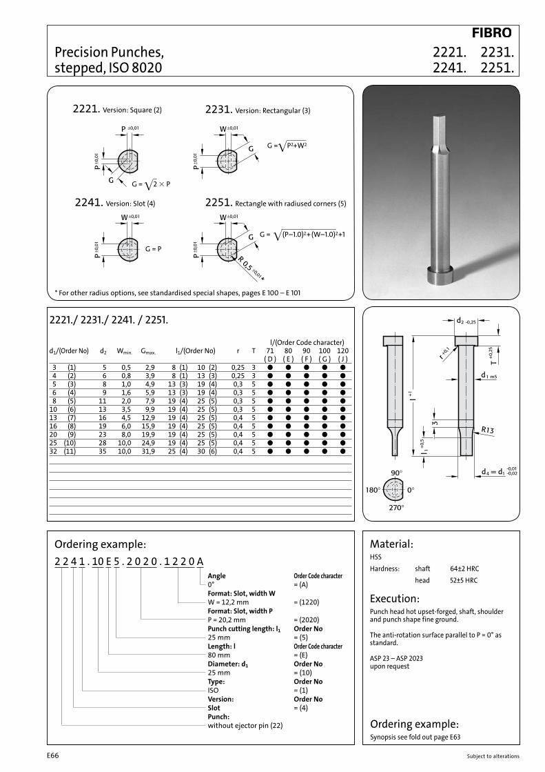
2221. 2231. 2241. 2251.
Precision Punches, stepped, ISO 8020
2221./ 2231./ 2241. / 2251.
l/(Order Code character) d1/(Order No) d2 Wmin. Gmax. l1/(Order No) r T 71 80 90 100 120 ( D ) ( E ) ( F ) ( G ) ( J ) 3 (1) 5 0,5 2,9 8 (1) 10 (2) 0,25 3 ● ● ● ● ● 4 (2) 6 0,8 3,9 8 (1) 13 (3) 0,25 3 ● ● ● ● ● 5 (3) 8 1,0 4,9 13 (3) 19 (4) 0,3 5 ● ● ● ● ● 6 (4) 9 1,6 5,9 13 (3) 19 (4) 0,3 5 ● ● ● ● ● 8 (5) 11 2,0 7,9 19 (4) 25 (5) 0,3 5 ● ● ● ● ●10 (6) 13 3,5 9,9 19 (4) 25 (5) 0,3 5 ● ● ● ● ●13 (7) 16 4,5 12,9 19 (4) 25 (5) 0,4 5 ● ● ● ● ●16 (8) 19 6,0 15,9 19 (4) 25 (5) 0,4 5 ● ● ● ● ●20 (9) 23 8,0 19,9 19 (4) 25 (5) 0,4 5 ● ● ● ● ●25 (10) 28 10,0 24,9 19 (4) 25 (5) 0,4 5 ● ● ● ● ●32 (11) 35 10,0 31,9 25 (4) 30 (6) 0,4 5 ● ● ● ● ●
Ordering example: 2 2 4 1 . 10 E 5 . 2 0 2 0 . 1 2 2 0 A Angle Order Code character 0° = (A) Format: Slot, width W W = 12,2 mm = (1220) Format: Slot, width P P = 20,2 mm = (2020) Punch cutting length: l1 Order No 25 mm = (5) Length: l Order Code character 80 mm = (E) Diameter: d1 Order No 25 mm = (10) Type: Order No ISO = (1) Version: Order No Slot = (4) Punch: without ejector pin (22)
Material:HSSHardness: shaft 64±2 HRC head 52±5 HRC
Execution:Punch head hot upset-forged, shaft, shoulder and punch shape fine ground.
The anti-rotation surface parallel to P = 0° as standard.
ASP 23 – ASP 2023 upon request
2221. Version: Square (2)
G = •(P–1.0)2+(W–1.0)2+1
G =•P2+W2
G = •2 3 P
G = P
2231. Version: Rectangular (3)
2241. Version: Slot (4) 2251. Rectangle with radiused corners (5)
Ordering example:Synopsis see fold out page E63
* For other radius options, see standardised special shapes, pages E 100 – E 101
Subject to alterationsE66

Precision Punches, blank, with ejector pin, ISO 8020
Material:HSSHardness: shaft 64±2 HRC head 52±5 HRC
Execution:Punch head hot upset-forged, shaft and shoulder fine ground.
2701.
Ordering example:2 7 0 1 . 11 G
Length: l Order Code character 100 mm = (G) Diameter: d1 Order No 32 mm = (11) Type: Order No ISO = (1) Version: Order No Blank = (0) Punch: with ejector pin (27)
2701.
l / (Order Code character)d1 / (Order No) d2 r T 71 80 90 100 120 ( D ) ( E ) ( F ) ( G ) ( J ) 5 (3) 8 0,3 5 ● ● ● ● ● 6 (4) 9 0,3 5 ● ● ● ● ● 8 (5) 11 0,3 5 ● ● ● ● ●10 (6) 13 0,3 5 ● ● ● ● ●13 (7) 16 0,4 5 ● ● ● ● ●16 (8) 19 0,4 5 ● ● ● ● ●20 (9) 23 0,4 5 ● ● ● ● ●25 (10) 28 0,4 5 ● ● ● ● ●32 (11) 35 0,4 5 ● ● ● ● ●
2701. Version: Blank (0)
Ordering example:Synopsis see fold out page E63
Subject to alterations E67

Precision Punches, stepped, with ejector pin, ISO 8020 2711.
2711.
l / (Order Code character)d1 / (Order No) d2 P l1 / (Order No) r T 71 80 90 100 120 D ) ( E ) ( F ) ( G ) ( J ) 5 (3) 8 1,6- 4,9 13 (3) 19 (4) 0,3 5 ● ● ● ● ● 6 (4) 9 2,5- 5,9 13 (3) 19 (4) 0,3 5 ● ● ● ● ● 8 (5) 11 2,5- 7,9 19 (4) 25 (5) 0,3 5 ● ● ● ● ●10 (6) 13 4,0- 9,9 19 (4) 25 (5) 0,3 5 ● ● ● ● ●13 (7) 16 5,0-12,9 19 (4) 25 (5) 0,4 5 ● ● ● ● ●16 (8) 19 8,0-15,9 19 (4) 25 (5) 0,4 5 ● ● ● ● ●20 (9) 23 12,0-19,9 19 (4) 25 (5) 0,4 5 ● ● ● ● ●25 (10) 28 16,5-24,9 19 (4) 25 (5) 0,4 5 ● ● ● ● ●32 (11) 35 20,0-31,9 25 (5) 30 (6) 0,4 5 ● ● ● ● ●
Ordering example: 2 7 1 1 . 7 G 4 . 0 7 0 0
Format: Round P = ø7,0 mm = (0700) Punch cutting length: l1 Order No 19 mm = (4) Length: l Order Code character 100 mm = (G) Diameter: d1 Order No 13 mm = (7) Type: Order No ISO = (1) Version: Order No Round = (1) Punch: with ejector pin (27)
Material:HSSHardness: shaft 64±2 HRC head 52±5 HRC
Execution:Punch head hot upset-forged, shaft, shoulder and punch diameter fine ground.
2711. Version: Round (1)
Ordering example:Synopsis see fold out page E63
Subject to alterationsE68

2721. 2731. 2741. 2751.
* For other radius options, see standardised special shapes, pages E 100 – E 101
Precision Punches, stepped, with ejector pin, ISO 8020
2721./ 2731./ 2741./ 2751.
l / (Order Code character)d1 / (Order No) d2 Wmin. Gmax. l1 / (Order No) r T 71 80 90 100 120 ( D ) ( E ) ( F ) ( G ) ( J ) 5 (3) 8 1,6 4,9 13 (3) 19 (4) 0,3 5 ● ● ● ● ● 6 (4) 9 2,5 5,9 13 (3) 19 (4) 0,3 5 ● ● ● ● ● 8 (5) 11 2,5 7,9 19 (4) 25 (5) 0,3 5 ● ● ● ● ●10 (6) 13 4,0 9,9 19 (4) 25 (5) 0,3 5 ● ● ● ● ●13 (7) 16 5,0 12,9 19 (4) 25 (5) 0,4 5 ● ● ● ● ●16 (8) 19 8,0 15,9 19 (4) 25 (5) 0,4 5 ● ● ● ● ●20 (9) 23 12,0 19,9 19 (4) 25 (5) 0,4 5 ● ● ● ● ●25 (10) 28 16,5 24,9 19 (4) 25 (5) 0,4 5 ● ● ● ● ●32 (11) 35 20,0 31,9 25 (5) 30 (6) 0,4 5 ● ● ● ● ●
Ordering example: 2 7 4 1 . 10 D 4 . 2 0 4 0 . 1 4 4 0 B Angle Order Code character 90° = (B) Format: Slot, width W W = 14,4mm = (1440) Format: Slot, length P P = 20,4 mm = (2040) Punch cutting length: l1 Order No 19 mm = (4) Length: l Order Code character 71 mm = (D) Diameter: d1 Order No 25 mm = (10) Type: Order No ISO = (1) Version: Order No Slot = (4) Punch: with ejector pin (27)
Material:HSSHardness: shaft 64±2 HRC head 52±5 HRC
Execution:Punch head hot upset-forged, shoulder, shaft and punch shape fine ground.
The anti-rotation surface parallel to P = 0° as standard.
2721. Version: Square (2)
G = •(P–1.0)2+(W–1.0)2+1
G =•P2+W2
G = •2 3 P
G = P
2731. Version: Rectangular (3)
2741. Version: Slot (4) 2751. Rectangle with radiused corners (5)
Ordering example:Synopsis see fold out page E63
Subject to alterations E69

Material:HSSHardness: shaft 64±2 HRC head 52±5 HRCExecution:Head hot upset-forged, shoulder, shaft and pilot fine ground.
2261.Pilot Pins with tapered tip, ISO 8020
2261.
l / (Order Code character)d1 / (Order No) d2 T P l1 / (Order No) N 63 71 80 90 100 110 125 140 ( C ) ( D ) ( E ) ( F ) ( G ) ( H ) ( K ) ( L ) 5 (3) 8 5 1,0- 4,9 13 (3) -- -- 4 ● ● 6 (4) 9 5 1,6- 5,9 13 (3) -- -- 5 ● ● ● 8 (5) 11 5 2,5- 7,9 13 (3) -- -- 6 ● ● ● ●10 (6) 13 5 4,0- 9,9 13 (3) 19 (4) -- 8 ● ● ● ● ● ● 13 (7) 16 5 5,0-12,9 13 (3) 19 (4) -- 10 ● ● ● ● ● ● ● 16 (8) 19 5 8,0-15,9 13 (3) 19 (4) 25 (5) 15 ● ● ● ● ● ● ●20 (9) 23 5 12,0-19,9 13 (3) 19 (4) 25 (5) 20 ● ● ● ● ● ● ●25 (10) 28 5 16,5-24,9 13 (3) 19 (4) 25 (5) 25 ● ● ● ● ● ● ●32 (11) 35 5 20,0-31,9 -- 19 (4) 25 (5) 30 ● ● ● ● ● ●
Ordering example:Synopsis see fold out page E63
Ordering example:2 2 6 1 . 10 D 3 . 1 7 5 0 Format: Round P = ø 17,5 mm = (1750) Punch cutting length l1 : Order No 25 mm = (3) Length: l Order Code character 71 mm = (D) Diameter: d1 Order No 32 mm = (10) Type: Order No ISO = (1) Version: Order No Pilot pin with tapered tip = (6) Punch: without ejector pin (22)
2261. Version: Pilot pin with tapered tip (6)
Subject to alterationsE70

P N ≦ 10 mm 8 mm 10,1 mm – 15 mm 12 mm > 15 mm 15 mm
2271.
Material:HSSHardness: shaft 64±2 HRC head 52±5 HRCExecution:Head hot upset-forged, shoulder, shaft and pilot fine ground. „l“ length of pilot pin is without tipNote: The 2 mm length provides full guidance before the blanking punch contacts the sheet metal.
Pilot Pins with parabolic tip, ISO 8020
Ordering example:Synopsis see fold out page E63
Ordering example:2 2 7 1 . 10 B 3 . 2 3 0 0 Format: Round P = ø 23 mm = (2300) Punch cutting length l1 : Order No 25 mm = (3) Length: l Order Code character 56 mm = (B) Diameter: d1 Order No 32 mm = (10) Type: Order No ISO = (1) Version: Order No Pilot pin parabolic tip = (7) Punch: without ejector pin (22)
2271.
l / (Order Code character)d1 / (Order No) d2 T P l1 / (Order No) 50 56 63 71 80 90 100 ( A ) ( B ) ( C ) ( D ) ( E ) ( F ) ( G ) 5 (3) 8 5 1,0- 4,9 10 (2) 13 (3) -- ● ● ● ● 6 (4) 9 5 1,6- 5,9 10 (2) 13 (3) -- ● ● ● ● ● 8 (5) 11 5 2,5- 7,9 10 (2) 13 (3) -- ● ● ● ● ●10 (6) 13 5 4,0- 9,9 10 (2) 13 (3) 19 (4) ● ● ● ● ● ● ●13 (7) 16 5 5,0-12,9 10 (2) 13 (3) 19 (4) ● ● ● ● ● ● ●16 (8) 19 5 8,0-15,9 -- 13 (3) 19 (4) ● ● ● ● ● ● ●20 (9) 23 5 12,0-19,9 -- 13 (3) 19 (4) ● ● ● ● ● ●25 (10) 28 5 16,5-24,9 -- 13 (3) 19 (4) ● ● ● ● ● ●32 (11) 35 5 20,0-31,9 -- -- 19 (4) ● ● ● ●
2271. Version: Pilot pin parabolic tip (7)
Subject to alterations E71

2276. Spring force in daNOrder No d d1 d2 d3 d4 d5 h h1 h2 l1 l2 l preloaded compressed2276.1. 9.8 10 10 18 18 15 28 25 12 47.5 39.3 63.2 4.9 6.22276.2. 15.8 16 16 24 30 26 28 25 12 54.5 46.3 72.5 4.8 5.6
2276.
Description:The pilot unit provides exact positioning of sheet metal parts. There are 2 sizes.The pilot unit 10 can used for a hole diameter of 5 ~ 10 mm and is available as a finished item, 9.8 mm diameter. Smaller diameters have to be ground by the tool making department.The pilot unit 16 is used for diameter 10 - 16 mm and is available as a blank, 15.8 mm diameter.
Material:The pilot unit consists of: Pilot pin, Casing, Compression spring, Parallel dowel pin.
Pilot Units to Daimler Standard 2276.
Ordering example: 2 2 7 6 . 1 . A . 0 9 8 0Diameter d
Length lA = 63,2 mmB = 72,5 mm
Diameter d11 = 10 mm2 = 16 mm
Daimler standard
Pilot pin
Subject to alterationsE72

Subject to alterations E73
Precision Matrixes

Subject to alterations E74

Subject to alterationsE75
Ordering examplePrecision Matrixes
2 6 4 6 . 1 0 F 6 . 1 3 5 0 . 0 6 5 0 A 2Anti-rotation element = Pin Ø4 (2)
Angle = 0° (A)
Format: Slot, width W = 6,5 mm (0650)
Format: Slot, length P = 13,5 mm (1350)
Shape cutting length: l = 8 mm (6)
Lenght: l1 = 28 mm (F)
Diameter: d2 = 32 mm (10)
Type = without shoulder ISO 8977 (6)
Version: Slot (4)
Matrixes:Matrixes (26)
Ordering Code (Example):
2 6 4 6 . 1 0 F 6 . 1 3 5 0 . 0 6 5 0 A 2
Matrixes: 26 matrixes
Format: Slot lenght P = 13,5 mm
Format: Slot width W = 6,5 mm
Type: Order Noautomotive standard = 5without shoulder ISO 8977 = 6with shoulder ISO 8977 = 7
Shape cutting lenght: l Order No 2 = 1 3 = 2 4 = 3 5 = 4 6 = 5 8 = 610 = 712 = 8special = X
Diameter: d2 Order No 5 = 1 6 = 2 8 = 3 10 = 4 13 = 5 16 = 6 20 = 7 22 = 8 25 = 9 32 = 10 38 = 11 40 = 12 45 = 13 50 = 14 56 = 15 63 = 16 71 = 17 76 = 18 86 = 19 90 = 20100 = 21
Order Code Length: l1 character13 = A16 = B20 = C22 = D25 = E28 = F30 = G32 = H35 = J40 = Kspecial = X
Order Code Angle: character 0° = A 90° = B180° = C270° = Dspecial = X
Anti-rotation Order element: Nopin Ø 3 = 1pin Ø 4 = 2pin Ø 6 = 3polished surface (continuous) = 4polished surface, top, 14 mm = 5polished surface, bottom, 14 mm = 6special = X
NB: See table for standard dimensions Special dimensions to order
Version: Order No blank (pilot hole bore) = 0 round = 1 square = 2 rectangular = 3 slot = 4 rectangle with radiused corners = 5 special shapes = 9

Subject to alterationsE76
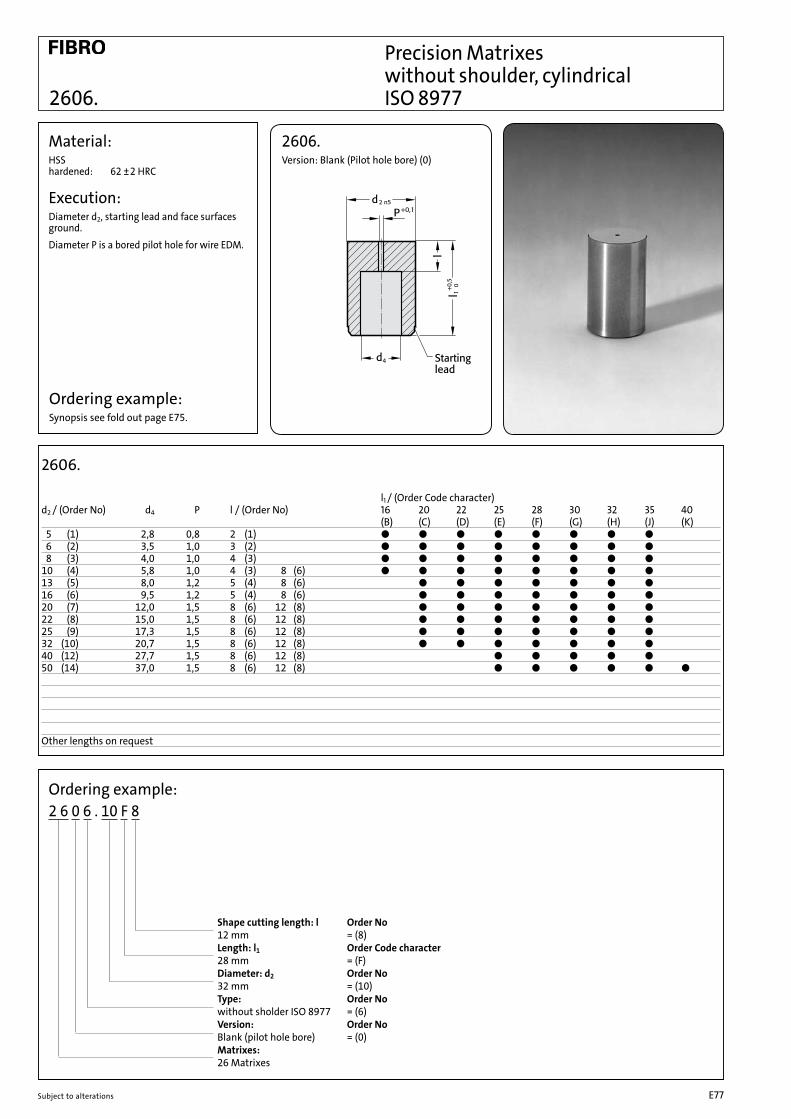
2606.
Precision Matrixes without shoulder, cylindrical ISO 8977
2606.
l1 / (Order Code character)d2 / (Order No) d4 P l / (Order No) 16 20 22 25 28 30 32 35 40 (B) (C) (D) (E) (F) (G) (H) (J) (K) 5 (1) 2,8 0,8 2 (1) ● ● ● ● ● ● ● ● 6 (2) 3,5 1,0 3 (2) ● ● ● ● ● ● ● ● 8 (3) 4,0 1,0 4 (3) ● ● ● ● ● ● ● ●10 (4) 5,8 1,0 4 (3) 8 (6) ● ● ● ● ● ● ● ●13 (5) 8,0 1,2 5 (4) 8 (6) ● ● ● ● ● ● ●16 (6) 9,5 1,2 5 (4) 8 (6) ● ● ● ● ● ● ●20 (7) 12,0 1,5 8 (6) 12 (8) ● ● ● ● ● ● ●22 (8) 15,0 1,5 8 (6) 12 (8) ● ● ● ● ● ● ●25 (9) 17,3 1,5 8 (6) 12 (8) ● ● ● ● ● ● ●32 (10) 20,7 1,5 8 (6) 12 (8) ● ● ● ● ● ● ●40 (12) 27,7 1,5 8 (6) 12 (8) ● ● ● ● ●50 (14) 37,0 1,5 8 (6) 12 (8) ● ● ● ● ● ●
Other lengths on request
Material:HSS hardened: 62 ±2 HRC
Execution:Diameter d2, starting lead and face surfaces ground.Diameter P is a bored pilot hole for wire EDM.
Ordering example:2 6 0 6 . 10 F 8
Shape cutting length: l Order No 12 mm = (8) Length: l1 Order Code character 28 mm = (F) Diameter: d2 Order No 32 mm = (10) Type: Order No without sholder ISO 8977 = (6) Version: Order No Blank (pilot hole bore) = (0) Matrixes: 26 Matrixes
2606. Version: Blank (Pilot hole bore) (0)
Ordering example:Synopsis see fold out page E75.
Subject to alterations E77

2616. Version: Round (1)
Material:HSS hardened: 62 ±2 HRC
Execution:Diameter d2, starting lead and face surfaces ground.
Precision Matrixes without shoulder, cylindrical ISO 8977 2616.
2616.
l1 / (Order Code character) d2 / (Order No) d4 P l / (Order No) 16 20 22 25 28 30 32 35 40 (B) (C) (D) (E) (F) (G) (H) (J) (K) 5 (1) 2,8 1,0- 2,4 2 (1) ● ● ● ● ● ● ● ● 6 (2) 3,5 1,6- 3,0 3 (2) ● ● ● ● ● ● ● ● 8 (3) 4,0 2,0- 3,5 4 (3) ● ● ● ● ● ● ● ●10 (4) 5,8 2,5- 5,0 4 (3) 8 (6) ● ● ● ● ● ● ● ●13 (5) 8,0 4,0- 7,0 5 (4) 8 (6) ● ● ● ● ● ● ●16 (6) 9,5 6,0- 9,0 5 (4) 8 (6) ● ● ● ● ● ● ●20 (7) 12,0 8,0-11,0 8 (6) 12 (8) ● ● ● ● ● ● ●22 (8) 15,0 9,0-14,0 8 (6) 12 (8) ● ● ● ● ● ● ●25 (9) 17,3 10,7-16,0 8 (6) 12 (8) ● ● ● ● ● ● ●32 (10) 20,7 15,0-20,0 8 (6) 12 (8) ● ● ● ● ● ● ●40 (12) 27,7 19,0-27,0 8 (6) 12 (8) ● ● ● ● ●50 (14) 37,0 26,0-36,0 8 (6) 12 (8) ● ● ● ● ● ●
Other lengths on request
Ordering example: without anti-rotation element
2 6 1 6 . 10 F 8 . 1 5 1 0
Format: Round P = ø 15,1 mm = (1510) Shape cutting length: l Order No 12 mm = (8) Length: l1 Order Code character 28 mm = (F) Diameter: d2 Order No 32 mm = (10) Type: Order No without sholder ISO 8977 = (6) Version: Order No Round = (1) Matrixes: 26 Matrixes
Ordering example: with anti-rotation element from d2 ≥ 10 mm
2 6 1 6 . 10 F 8 . 1 5 1 0 A 4 Anti-rotation element: Order No Polished surface = (4) (continuous) Angle: Order Code character 0° = (A) Format: Round P = ø15,1 mm = (1510) FormschneidLength: l Order No 12 mm = (8) Length: l1 Order Code character 28 mm = (F) Diameter: d2 Order No 32 mm = (10) Type: Order No without sholder ISO 8977 = (6) Version: Order No Round = (1) Matrixes: 26 Matrixes
Ordering example:Synopsis see fold out page E75.
Subject to alterationsE78

Precision Matrixes without shoulder, cylindrical , ISO 8977 Anti-rotation elements
Pin [3d2 F 10 5 13 6,5 16 8 20 10 22 11 25 12,5 32 16 40 20 50 25
Pin [4d2 F 10 6 13 7,2 16 8 20 10 22 11 25 12,5 32 16 40 20 50 25
Pin [6d2 F 10 7 13 8,2 16 9 20 11 22 12 25 13,5 32 16 40 20 50 25
d2 F 10 4 13 5,5 16 7 20 8,5 22 9,5 25 11 32 14 40 18 50 23
d2 F 10 4 13 5,5 16 7 20 8,5 22 9,5 25 11 32 14 40 18 50 23
d2 F 10 4 13 5,5 16 7 20 8,5 22 9,5 25 11 32 14 40 18 50 23
anti-rotation element 1 (1) anti-rotation element 2 (2) anti-rotation element 3 (3)
anti-rotation element 4 (4) anti-rotation element 5 (5) anti-rotation element 6 (6)
Ordering example:Synopsis see fold out page E75.
Subject to alterations E79

G = P
Precision Matrixes without shoulder, cylindrical ISO 8977
Material:HSS hardened: 62 ±2 HRC
Execution:Diameter d2, starting lead and face surfaces ground.
* For other radius options, see standardised special shapes, pages E100 – E101.
G = •(P–1.0)2+(W–1.0)2+1
G =•P2+W2
G = •2 3 P
2626. 2636. 2646. 2656.
2626. Version: Square (2) 2636. Version: Rectangular (3)
2646. Version: Slot (4) 2656. Version: Rectangle with radiused corners (5)
2626./ 2636./ 2646./ 2456.
l1 / (Order Code character) d2 / (Order No) d4 Wmin. Gmax. l / (Order No) 16 20 22 25 28 30 32 35 40 (B) (C) (D) (E) (F) (G) (H) (J) (K)10 (4) 5,8 1,2 5,0 4 (3) 8 (6) ● ● ● ● ● ● ● ●13 (5) 8,0 2,0 7,0 5 (4) 8 (6) ● ● ● ● ● ● ●16 (6) 9,5 2,4 9,0 5 (4) 8 (6) ● ● ● ● ● ● ●20 (7) 12,0 3,2 11,0 8 (6) 12 (8) ● ● ● ● ● ● ●22 (8) 15,0 4,0 14,0 8 (6) 12 (8) ● ● ● ● ● ● ●25 (9) 17,3 4,8 16,0 8 (6) 12 (8) ● ● ● ● ● ● ●32 (10) 20,7 5,5 20,0 8 (6) 12 (8) ● ● ● ● ● ● ●40 (12) 27,7 6,4 27,0 8 (6) 12 (8) ● ● ● ● ●50 (14) 37,0 9,0 36,0 8 (6) 12 (8) ● ● ● ● ● ●
Other lengths on request
Ordering example:Synopsis see fold out page E75.
Subject to alterationsE80

Ordering example:Synopsis see fold out page E75.
Ordering example:2 6 3 6 . 10 F 8 . 1 3 5 0 . 0 6 5 0 A 4 Anti-rotation element: Order No Polished surface = (4) (continuous) Angle: Order Code character 0° = (A) Format: Rectangular, width W W = 6,5 mm = (0650) Format: Rectangular, length P P = 13,5 mm = (1350) Shape cutting length: l Order No 12 mm = (8) Length: l1 Order Code character 28 mm = (F) Diameter: d2 Order No 32 mm = (10) Type: Order No without sholder ISO 8977 = (6) Version: Order No Rectangular = (3) Matrixes: 26 Matrixes
Precision Matrixes without shoulder, cylindrical , ISO 8977 Anti-rotation elements
Pin [3d2 F 10 5 13 6,5 16 8 20 10 22 11 25 12,5 32 16 40 20 50 25
Pin [4d2 F 10 6 13 7,2 16 8 20 10 22 11 25 12,5 32 16 40 20 50 25
Pin [6d2 F 10 7 13 8,2 16 9 20 11 22 12 25 13,5 32 16 40 20 50 25
d2 F 10 4 13 5,5 16 7 20 8,5 22 9,5 25 11 32 14 40 18 50 23
d2 F 10 4 13 5,5 16 7 20 8,5 22 9,5 25 11 32 14 40 18 50 23
d2 F 10 4 13 5,5 16 7 20 8,5 22 9,5 25 11 32 14 40 18 50 23
anti-rotation element 1 (1) anti-rotation element 2 (2) anti-rotation element 3 (3)
anti-rotation element 4 (4) anti-rotation element 5 (5) anti-rotation element 6 (6)
Subject to alterations E81

Subject to alterationsE82

2607.
Material:HSS hardened: 62 ±2 HRC
Execution:Diameter d2, and end faces ground.
Diameter P is a bored pilot hole for wire EDM.
2607. Version: Blank (pilot hole bore) (0)
Precision Matrixes with shoulder, cylindrical, ISO 8977
Ordering example:2 6 0 7 . 10 F 8
Shape cutting length: l Order No 12 mm = (8) Length: l1 Order Code character 28 mm = (F) Diameter: d2 Order No 32 mm = (10) Type: Order No with sholder ISO 8977 = (7) Version: Order No Blank (pilot hole bore) = (0) Matrixes: 26 Matrixes
2607.
l1 /(Order Code character) d2 /(Order No) d3 d4 P l /(Order No) 16 20 22 25 28 30 32 35 (B) (C) (D) (E) (F) (G) (H) (J) 5 (1) 8 2,8 0,8 2 (1) ● ● ● ● ● ● ● ● 6 (2) 9 3,5 1,0 3 (2) ● ● ● ● ● ● ● ● 8 (3) 11 4,0 1,0 4 (3) ● ● ● ● ● ● ● ●10 (4) 13 5,8 1,0 4 (3) 8 (6) ● ● ● ● ● ● ● ●13 (5) 16 8,0 1,2 5 (4) 8 (6) ● ● ● ● ● ● ●16 (6) 19 9,5 1,2 5 (4) 8 (6) ● ● ● ● ● ● ●20 (7) 23 12,0 1,5 8 (6) 12 (8) ● ● ● ● ● ● ●22 (8) 25 15,0 1,5 8 (6) 12 (8) ● ● ● ● ● ● ●25 (9) 28 17,3 1,5 8 (6) 12 (8) ● ● ● ● ● ● ●32 (10) 35 20,7 1,5 8 (6) 12 (8) ● ● ● ● ● ● ●40 (12) 43 27,7 1,5 8 (6) 12 (8) ● ● ● ● ● ● ●50 (14) 53 37,0 1,5 8 (6) 12 (8) ● ● ● ● ● ● ●
Other lengths on request
Ordering example:Synopsis see fold out page E75.
Subject to alterations E83

Precision Matrixes with shoulder, cylindrical, ISO 8977 2617.
Material:HSS hardened: 62 ±2 HRC
Execution:Diameter d2, and end faces ground.
2617. Version: Round (1)
Ordering example: without anti-rotation element
2 6 1 7 . 10 F 8 . 1 5 1 0
Format: Round P = ø 15,1 mm = (1510) Shape cutting length: l Order No 12 mm = (8) Length: l1 Order Code character 28 mm = (F) Diameter: d2 Order No 32 mm = (10) Type: Order No with sholder ISO 8977 = (7) Version: Order No Round = (1) Matrixes: 26 Matrixes
Ordering example: with anti-rotation element from d2 ≥ 8 mm
2 6 1 7 . 10 F 8 . 1 5 1 0 A 4 Anti-rotation element: Order No Polished surface = (4) (continuous) Angle: Order Code character 0° = (A) Format: Round P = ø15,1 mm = (1510) Shape cutting length: l Order No 12 mm = (8) Length: l1 Order Code character 28 mm = (F) Diameter: d2 Order No 32 mm = (10) Type: Order No with sholder ISO 8977 = (7) Version: Order No Round = (1) Matrixes: 26 Matrixes
2617.
l1 / (Order Code character) d2 / (Order No) d3 d4 P l / (Order No) 16 20 22 25 28 30 32 35 (B) (C) (D) (E) (F) (G) (H) (J) 5 (1) 8 2,8 1,0- 2,4 2 (1) ● ● ● ● ● ● ● ● 6 (2) 9 3,5 1,6- 3,0 3 (2) ● ● ● ● ● ● ● ● 8 (3) 11 4,0 2,0- 3,5 4 (3) ● ● ● ● ● ● ● ●10 (4) 13 5,8 2,5- 5,0 4 (3) 8 (6) ● ● ● ● ● ● ● ●13 (5) 16 8,0 4,0- 7,0 5 (4) 8 (6) ● ● ● ● ● ● ●16 (6) 19 9,5 6,0- 9,0 5 (4) 8 (6) ● ● ● ● ● ● ●20 (7) 23 12,0 8,0-11,0 8 (6) 12 (8) ● ● ● ● ● ● ●22 (8) 25 15,0 9,0-14,0 8 (6) 12 (8) ● ● ● ● ● ● ●25 (9) 28 17,3 10,7-16,0 8 (6) 12 (8) ● ● ● ● ● ● ●32 (10) 35 20,7 15,0-20,0 8 (6) 12 (8) ● ● ● ● ● ● ●40 (12) 43 27,7 19,0-27,0 8 (6) 12 (8) ● ● ● ● ● ● ●50 (14) 53 37,0 26,0-36,0 8 (6) 12 (8) ● ● ● ● ● ● ●
Other lengths on request
Ordering example:Synopsis see fold out page E75.
Subject to alterationsE84

Ordering example:Synopsis see fold out page E75.
Precision Matrixes with shoulder, cylindrical, ISO 8977 Anti-rotation elements
Pin [3d2 F 8 5,5 10 6,5 13 8 16 9,5 20 11,5 22 12,5 25 14 32 17,5 40 21,5 50 26,5
Pin [4d2 F 8 6 10 7 13 8,5 16 10 20 12 22 13 25 14,5 32 18 40 22 50 27
Pin [6d2 F 8 7 10 8 13 9,5 16 11 20 13 22 14 25 15,5 32 19 40 23 50 28
Anti-rotation element 1 (1) Anti-rotation element 2 (2) Anti-rotation element 3 (3)
Anti-rotation element 4 (4)
Subject to alterations E85

G = P
Precision Matrixes with shoulder, cylindrical ISO 8977
Material:HSS hardened: 62 ±2 HRC
Execution:Diameter d2, and end faces ground.
* For other radius options, see standardised special shapes, pages E100 – E101.
G = •(P–1.0)2+(W–1.0)2+1
G =•P2+W2
G = •2 3 P
2627. 2637. 2647. 2657.
2627. Version: Square (2) 2637. Version: Rectangular (3)
2647. Version: Slot (4)2657. Version: Rectangle with radiused
corners (5)
2627./ 2637./ 2647./ 2457.
l1 /(Order Code character) d2 /(Order No) d3 d4 Wmin. Gmax. l /(Order No) 16 20 22 25 28 30 32 35 (B) (C) (D) (E) (F) (G) (H) (J) 8 (3) 11 4,0 1,2 3,5 4 (3) ● ● ● ● ● ● ● ●10 (4) 13 5,8 1,2 5,0 4 (3) 8 (6) ● ● ● ● ● ● ● ●13 (5) 16 8,0 2,0 7,0 5 (4) 8 (6) ● ● ● ● ● ● ●16 (6) 19 9,5 2,4 9,0 5 (4) 8 (6) ● ● ● ● ● ● ●20 (7) 23 12,0 3,2 11,0 8 (6) 12 (8) ● ● ● ● ● ● ●22 (8) 25 15,0 4,0 14,0 8 (6) 12 (8) ● ● ● ● ● ● ●25 (9) 28 17,3 4,8 16,0 8 (6) 12 (8) ● ● ● ● ● ● ●32 (10) 35 20,7 5,5 20,0 8 (6) 12 (8) ● ● ● ● ● ● ●40 (12) 43 27,7 6,4 27,0 8 (6) 12 (8) ● ● ● ● ● ● ●50 (14) 53 37,0 6,4 36,0 8 (6) 12 (8) ● ● ● ● ● ● ●
Other lengths on request
Ordering example:Synopsis see fold out page E75.
Subject to alterationsE86
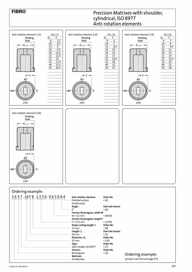
Ordering example:Synopsis see fold out page E75.
Ordering example:2 6 3 7 . 10 F 8 . 1 3 5 0 . 0 6 5 0 A 4 Anti-rotation element: Order No Polished surface = (4) (continuous) Angle: Order Code character 0° = (A) Format: Rectangular, width W W = 6,5 mm = (0650) Format: Rectangular, length P P = 13,5 mm = (1350) Shape cutting length: l Order No 12 mm = (8) Length: l1 Order Code character 28 mm = (F) Diameter: d2 Order No 32 mm = (10) Type: Order No with sholder ISO 8977 = (7) Version: Order No Rectangular = (3) Matrixes: 26 Matrixes
Precision Matrixes with shoulder, cylindrical, ISO 8977 Anti-rotation elements
Pin [3d2 F 8 5,5 10 6,5 13 8 16 9,5 20 11,5 22 12,5 25 14 32 17,5 40 21,5 50 26,5
Pin [4d2 F 8 6 10 7 13 8,5 16 10 20 12 22 13 25 14,5 32 18 40 22 50 27
Pin [6d2 F 8 7 10 8 13 9,5 16 11 20 13 22 14 25 15,5 32 19 40 23 50 28
Anti-rotation element 1 (1) Anti-rotation element 2 (2) Anti-rotation element 3 (3)
Anti-rotation element 4 (4)
Subject to alterations E87

Matrixes without shoulder, automotive standard 2605.
Ordering example:2 6 0 5 . 10 F
Length: l1 Order Code character 28 mm = (F) Diameter: d2 Order No 32 mm = (10) Type: Order No without sholder Automotive Stadard = (5) Version: Order No Blank (pilot hole bore) = (0) Matrixes: 26 Matrixes
Material:HSS hardened: 62±2 HRC
Execution:Diameter d2, and end faces ground.Diameter P is a bored pilot hole for wire EDM
2605. Version: Blank (pilot hole bore) (0)
2605. l1 /(Order Code character) d2 /(Order No) P 13 16 20 22 25 28 30 32 35 40 ( A ) ( B ) ( C ) ( D ) ( E ) ( F ) ( G ) ( H ) ( J ) ( K ) 10 (4) 0,8 ● ● ● ● ● ● ● ● ● 13 (5) 0,8 ● ● ● ● ● ● ● ● ● 16 (6) 1,5 ● ● ● ● ● ● ● 20 (7) 2,4 ● ● ● ● ● ● ● 22 (8) 3,0 ● ● ● ● ● ● ● 25 (9) 3,0 ● ● ● ● ● ● ● 32 (10) 3,0 ● ● ● ● ● ● ● 38 (11) 3,0 ● ● ● ● ● ● ● ● 40 (12) 3,0 ● ● ● ● ● ● ● 45 (13) 3,0 ● ● ● ● ● ● ● 50 (14) 3,0 ● ● ● ● ● ● ● 56 (15) 3,0 ● ● ● ● ● ● ● 63 (16) 3,0 ● ● ● ● ● ● ● 71 (17) 3,0 ● ● ● ● ● ● ● 76 (18) 3,0 ● ● ● ● ● ● 86 (19) 3,0 ● ● ● ● ● ● 90 (20) 3,0 ● ● ● ● ● ●100 (21) 3,0 ● ● ● ● ● ●
Other lengths on request
Ordering example:Synopsis see fold out page E75.
Subject to alterationsE88
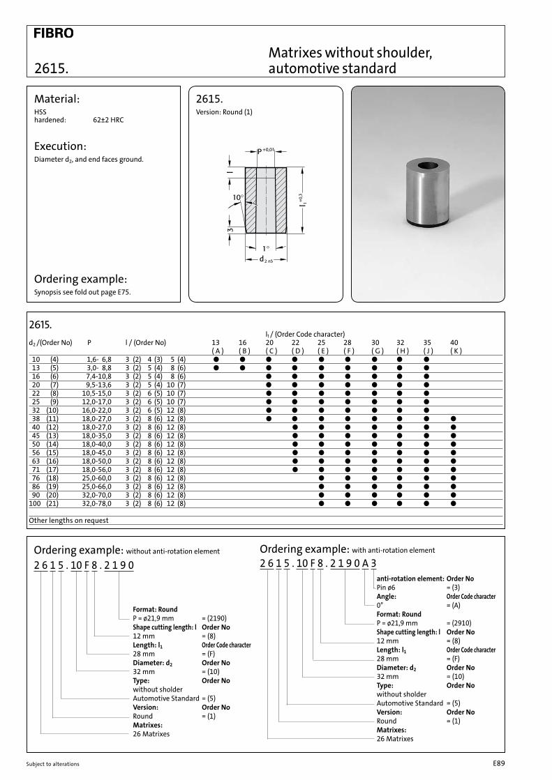
Matrixes without shoulder, automotive standard2615.
Material:HSS hardened: 62±2 HRC
Execution:Diameter d2, and end faces ground.
2615. Version: Round (1)
Ordering example: with anti-rotation element
2 6 1 5 . 10 F 8 . 2 1 9 0 A 3 anti-rotation element: Order No Pin ø6 = (3) Angle: Order Code character 0° = (A) Format: Round P = ø21,9 mm = (2910) Shape cutting length: l Order No 12 mm = (8) Length: l1 Order Code character 28 mm = (F) Diameter: d2 Order No 32 mm = (10) Type: Order No without sholder Automotive Standard = (5) Version: Order No Round = (1) Matrixes: 26 Matrixes
2615. l1 / (Order Code character) d2 /(Order No) P l / (Order No) 13 16 20 22 25 28 30 32 35 40 ( A ) ( B ) ( C ) ( D ) ( E ) ( F ) ( G ) ( H ) ( J ) ( K ) 10 (4) 1,6- 6,8 3 (2) 4 (3) 5 (4) ● ● ● ● ● ● ● ● ● 13 (5) 3,0- 8,8 3 (2) 5 (4) 8 (6) ● ● ● ● ● ● ● ● ● 16 (6) 7,4-10,8 3 (2) 5 (4) 8 (6) ● ● ● ● ● ● ● 20 (7) 9,5-13,6 3 (2) 5 (4) 10 (7) ● ● ● ● ● ● ● 22 (8) 10,5-15,0 3 (2) 6 (5) 10 (7) ● ● ● ● ● ● ● 25 (9) 12,0-17,0 3 (2) 6 (5) 10 (7) ● ● ● ● ● ● ● 32 (10) 16,0-22,0 3 (2) 6 (5) 12 (8) ● ● ● ● ● ● ● 38 (11) 18,0-27,0 3 (2) 8 (6) 12 (8) ● ● ● ● ● ● ● ● 40 (12) 18,0-27,0 3 (2) 8 (6) 12 (8) ● ● ● ● ● ● ● 45 (13) 18,0-35,0 3 (2) 8 (6) 12 (8) ● ● ● ● ● ● ● 50 (14) 18,0-40,0 3 (2) 8 (6) 12 (8) ● ● ● ● ● ● ● 56 (15) 18,0-45,0 3 (2) 8 (6) 12 (8) ● ● ● ● ● ● ● 63 (16) 18,0-50,0 3 (2) 8 (6) 12 (8) ● ● ● ● ● ● ● 71 (17) 18,0-56,0 3 (2) 8 (6) 12 (8) ● ● ● ● ● ● ● 76 (18) 25,0-60,0 3 (2) 8 (6) 12 (8) ● ● ● ● ● ● 86 (19) 25,0-66,0 3 (2) 8 (6) 12 (8) ● ● ● ● ● ● 90 (20) 32,0-70,0 3 (2) 8 (6) 12 (8) ● ● ● ● ● ●100 (21) 32,0-78,0 3 (2) 8 (6) 12 (8) ● ● ● ● ● ●
Other lengths on request
Ordering example: without anti-rotation element
2 6 1 5 . 10 F 8 . 2 1 9 0
Format: Round P = ø21,9 mm = (2190) Shape cutting length: l Order No 12 mm = (8) Length: l1 Order Code character 28 mm = (F) Diameter: d2 Order No 32 mm = (10) Type: Order No without sholder Automotive Standard = (5) Version: Order No Round = (1) Matrixes: 26 Matrixes
Ordering example:Synopsis see fold out page E75.
Subject to alterations E89

G = P
2625. 2635. 2645. 2655.
Pin [6d2 F 10 7 13 8,2 16 9 20 11 22 12 25 13,5 32 16 38 19 40 20 45 22,5 50 25 56 28 63 31,5 71 35,5 76 38 85 42,5 90 45100 50
Anti-rotation element 3 (3)
* For other radius options, see standardised special shapes, pages E100 – E101.
2625. Version: Square (2) 2635. Version: Rectangular (3)
2645. Version: Slot (4) 2655. Version: Rectangle with radiused corners (5)
G = •(P–1.0)2+(W–1.0)2+1
G = •P2+W2G = •2 3 P
Matrixes without shoulder, automotive standard
2625./ 2635./ 2645./ 2655. l1 /(Order Code character) d2 /(Order No) Wmin Gmax l /(Order No) 13 16 20 22 25 28 30 32 35 40 (A) (B) (C) (D) (E) (F) (G) (H) (J) (K) 10 (4) 1,3 6,8 3 (2) 4 (3) 5 (4) ● ● ● ● ● ● ● ● ● 13 (5) 1,9 8,8 3 (2) 5 (4) 8 (6) ● ● ● ● ● ● ● ● ● 16 (6) 1,9 10,8 3 (2) 5 (4) 8 (6) ● ● ● ● ● ● ● 20 (7) 1,9 13,6 3 (2) 5 (4) 10 (7) ● ● ● ● ● ● ● 22 (8) 1,9 15,0 3 (2) 6 (5) 10 (7) ● ● ● ● ● ● ● 25 (9) 1,9 17,0 3 (2) 6 (5) 10 (7) ● ● ● ● ● ● ● 32 (10) 1,9 22,0 3 (2) 6 (5) 12 (8) ● ● ● ● ● ● ● 38 (11) 1,9 27,0 3 (2) 8 (6) 12 (8) ● ● ● ● ● ● ● 40 (12) 1,9 27,0 3 (2) 8 (6) 12 (8) ● ● ● ● ● ● ● 45 (13) 2,4 35,0 3 (2) 8 (6) 12 (8) ● ● ● ● ● ● ● 50 (14) 4,0 40,0 3 (2) 8 (6) 12 (8) ● ● ● ● ● ● ● 56 (15) 4,0 45,0 3 (2) 8 (6) 12 (8) ● ● ● ● ● ● ● 63 (16) 4,0 50,0 3 (2) 8 (6) 12 (8) ● ● ● ● ● ● ● 71 (17) 4,0 56,0 3 (2) 8 (6) 12 (8) ● ● ● ● ● ● 76 (18) 5,6 60,0 3 (2) 8 (6) 12 (8) ● ● ● ● ● ● 86 (19) 5,6 66,0 3 (2) 8 (6) 12 (8) ● ● ● ● ● ● 90 (20) 5,6 70,0 3 (2) 8 (6) 12 (8) ● ● ● ● ● ●100 (21) 5,6 78,0 3 (2) 8 (6) 12 (8) ● ● ● ● ● ●
Other lengths on request
Material: HSS hardened 62±2 Execution: Diameter d2 and end
faces ground.
Ordering example: without anti-rotation element
2 6 3 5 . 10 F 8 . 1 3 5 0 . 0 6 5 0 A 3 Anti-rotation element: Order No Pin ø6 = (3) Angle: Order Code character 0° = (A) Format: Rectangular, width W W = 6,5 mm = (0650) Format: Rectangular, length P P = 13,5 mm = (1350) Shape cutting length: l Order No 12 mm = (8) Length: l1 Order Code character 28 mm = (F) Diameter: d2 Order No 32 mm = (10) Type: Order No without sholder Automotive Standard = (5) Version: Order No Square = (3) Matrixes: 26 Matrixes
Ordering example:Synopsis see fold out page E75.
Subject to alterationsE90
Subject to alterations E91
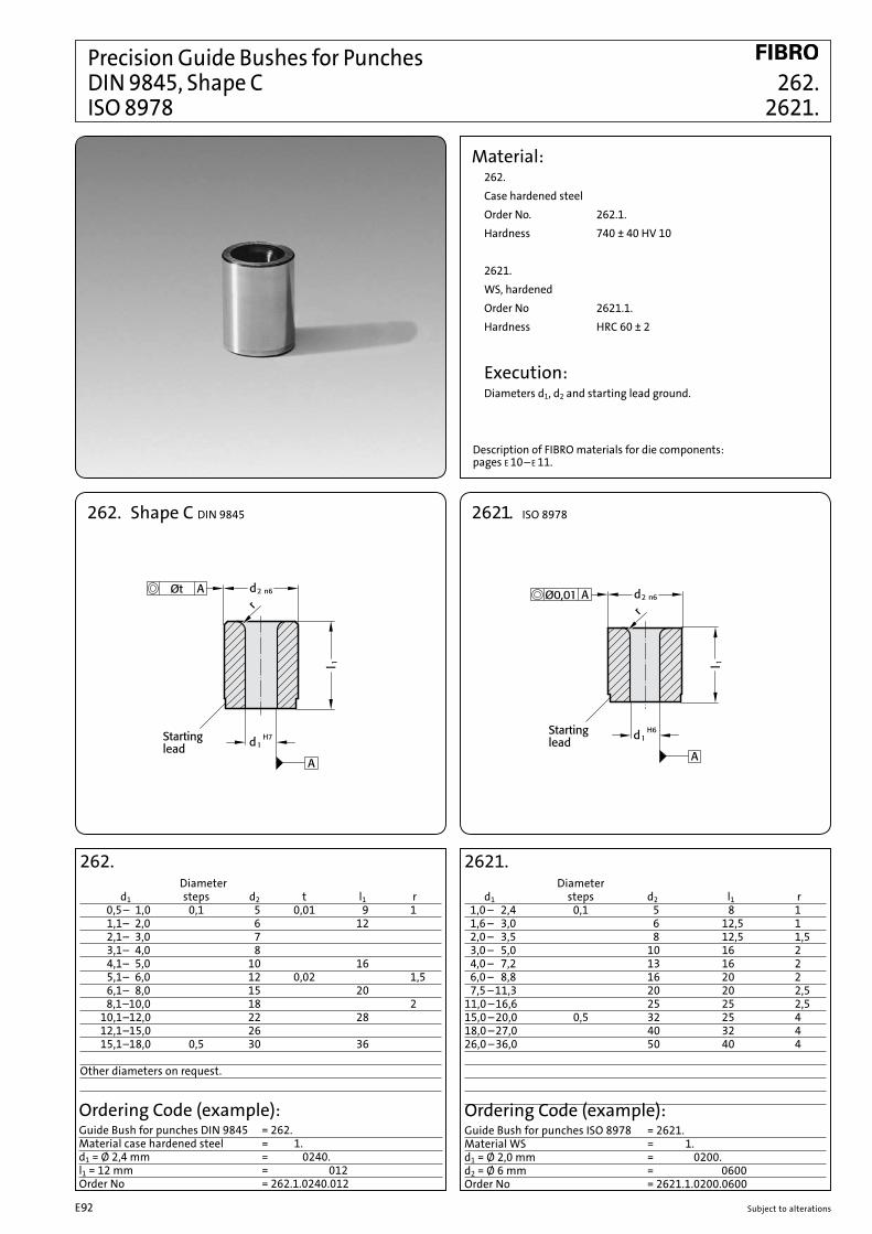
262. Diameter d1 steps d2 t l1 r 0,5 – 1,0 0,1 5 0,01 9 1 1,1– 2,0 6 12 2,1– 3,0 7 3,1– 4,0 8 4,1– 5,0 10 16 5,1– 6,0 12 0,02 1,5 6,1– 8,0 15 20 8,1–10,0 18 2 10,1–12,0 22 28 12,1–15,0 26 15,1–18,0 0,5 30 36 Other diameters on request.
Ordering Code (example):Guide Bush for punches DIN 9845 = 262.Material case hardened steel = 1.d1 = Ø 2,4 mm = 0240.l1 = 12 mm = 012Order No = 262.1.0240.012
2621. Diameter d1 steps d2 l1 r 1,0 – 2,4 0,1 5 8 1 1,6 – 3,0 6 12,5 1 2,0 – 3,5 8 12,5 1,5 3,0 – 5,0 10 16 2 4,0 – 7,2 13 16 2 6,0 – 8,8 16 20 2 7,5 – 11,3 20 20 2,511,0 – 16,6 25 25 2,515,0 – 20,0 0,5 32 25 418,0 – 27,0 40 32 426,0 – 36,0 50 40 4
Material:262.Case hardened steelOrder No. 262.1.Hardness 740 ± 40 HV 10
2621.WS, hardenedOrder No 2621.1.Hardness HRC 60 ± 2
Execution:Diameters d1, d2 and starting lead ground.
2621. ISO 8978262. Shape C DIN 9845
Precision Guide Bushes for Punches DIN 9845, Shape C 262. ISO 8978 2621.
Description of FIBRO materials for die components: pages E 10– E 11.
Ordering Code (example):Guide Bush for punches ISO 8978 = 2621.Material WS = 1.d1 = Ø 2,0 mm = 0200.d2 = Ø 6 mm = 0600Order No = 2621.1.0200.0600
Subject to alterationsE92

Precision Matrixes 260. with and without collar DIN 9845 261. Shape A, Shape B
Material:HSSOrder No: Shape A = 260.3. Shape B = 261.3.Hardness: 62 ± 2 HRC
Execution:Diameters d1, d2 and face surfaces ground.
260. Diameter short long d1 steps d2 d4 l1 l2 l1 l2 0,5– 1,0 0,1 5 d1 +0,3 20 18 – – 1,1– 2,0 6 17 28 25 2,1– 3,0 7 d1 +0,5 3,1– 4,0 8 4,1 –5,0 10 d1 +0,7 16 24 5,1– 6,0 12 6,1– 8,0 15 8,1–10,0 18 d1 +1 10,1–12,0 22 15 23 12,1–15,0 26 15,1–18,0 30 – – Other diameters on request.
261. Diameter short long d1 steps d2 d3 d4 l1 l2 l3 l1 l2 l3 0,5– 1,0 0,1 5 7 d1 +0,3 20 18 16 – – – 1,1– 2,0 6 8 17 28 25 24 2,1– 3,0 7 9 d1 +0,5 3,1– 4,0 8 10 4,1 –5,0 10 12 d1 +0,7 16 24 5,1– 6,0 12 14 6,1– 8,0 15 17 8,1–10,0 18 20 d1 +1 10,1–12,0 22 24 15 23 12,1–15,0 26 28 15,1–18,0 30 32 – – –
Ordering Code (example):Matrix = 261.Material HSS = 3.d1 = Ø 2,20 mm = 0220.l1 = 28 mm = 028Order No = 261.3.0220.028
260. Shape A
261. Shape B
Description of FIBRO materials for die components: pages E 10– E 11.
Subject to alterations E93

Precision Matrixes with and without collar 2602. cylindrical 2612.
2602.
*d1= size over corners
Classified Shape
Material:HSS Order No.: 2602. o. 2612.3. Hardness: 64±2 HRC
Execution:Diameters d2 and face surfaces ground.Key flats parallel with unless otherwise specified.
2602. L1 d1, d5 d2 L F 16 19 22 25 28 32 1,8 – 3,2 8 3 1,0 ● ● ● ● ● ● 2,0 – 5,0 10 ● ● ● ● ● ● 3,0 – 7,0 13 1,5 ● ● ● ● ● ● 5,0 – 8,0 16 5 ● ● ● ● ● ● 7,0 – 11,0 20 ● ● ● ● ● ● 11,0 – 16,0 25 2,5 ● ● ● ● ● ● 16,0 – 19,0 32 7 ● ● ● ● ● ● 19,0 – 28,0 40 ● ● ● ● ● ●
Size over corners
Ordering code (example):Matrix = 2602.Material HSS = 2602.3.d2 = 16 mm = 2602.2.016.L1 = 32 mm = 2602.2.016.032.Shape 2 = 2602.2.016.032.2.a = 3,96 mm = 2602.2.016.032.2.0396.b = 5,16 mm = 2602.2.016.032.2.0396.0516Order No = 2602.3.016.032.2.0396.0516
2612. L1 d1, d5 d2 d3 L 16 19 22 25 28 32 1,8 – 3,2 8 11 3 ● ● ● ● ● ● 2,0 – 5,0 10 13 ● ● ● ● ● ● 3,0 – 7,0 13 16 ● ● ● ● ● ● 5,0 – 8,0 16 19 5 ● ● ● ● ● ● 7,0 – 11,0 20 23 ● ● ● ● ● ● 11,0 – 16,0 25 28 ● ● ● ● ● ● 16,0 – 19,0 32 35 7 ● ● ● ● ● ● 19,0 – 28,0 40 43 ● ● ● ● ● ●
Size over corners
Ordering code (example):Matrix = 2612.Material HSS = 2612.3.d2 = 16 mm = 2612.2.016.L1 = 28 mm = 2612.2.016.028.Shape 2 = 2612.2.016.028.2.a = 3,96 mm = 2612.2.016.028.2.0396.b = 5,16 mm = 2612.2.016.028.2.0396.0516Order No = 2612.3.016.028.2.0396.0516
2612.
*d1= size over corners
With starting holes for wire-EDM as per 2601. page E95
A
Subject to alterationsE94

Precision Matrixes 2601. with and without collar 2611. conical
Classified shapes
Material: HS Order No.: 2601. o. 2611.3. Hardness: 64 ± 2 HRC
Execution: Diameters d2 precision ground; face surfaces ground. Key flats parallel with unless otherwise specified.
2601. *d1 = size over corners
2611. *d1 = size over corners
* Shape 0 = with starting hole for wire cut
2601. Size over corners L1 d1, d5 d2 d4 F 16 19 22 25 28 32 1,8– 3,2 8 1,0 1,0 ● ● ● ● ● ● 2,0– 5,0 10 ● ● ● ● ● ● 3,0– 7,0 13 1,5 1,5 ● ● ● ● ● ● 5,0– 8,0 16 ● ● ● ● ● ● 7,0–11,0 20 ● ● ● ● ● ● 11,0–16,0 25 2,5 2,5 ● ● ● ● ● ● 16,0–19,0 32 ● ● ● ● ● ● 19,0–28,0 40 ● ● ● ● ● ●
Ordering Code (example):Matrix = 2601.2.016.032.2.0396.0516.Material HSS = 2601.3.016.032.2.0396.0516.d2 = 16 mm = 2601.2.016.032.2.0396.0516.L1 = 32 mm = 2601.2.016.032.2.0396.0516.Shape 2 = 2601.2.016.032.2.0396.0516.a = 3,96 mm = 2601.2.016.032.2.0396.0516.b = 5,16 mm = 2601.2.016.032.2.0396.0516Order No = 2601.3.016.032.2.0396.0516
2611. Size over corners L1 d1, d5 d2 d3 d4 16 19 22 25 28 32 1,8– 3,2 8 11 1,0 ● ● ● ● ● ● 2,0– 5,0 10 13 ● ● ● ● ● ● 3,0– 7,0 13 16 1,5 ● ● ● ● ● ● 5,0– 8,0 16 19 ● ● ● ● ● ● 7,0–11,0 20 23 ● ● ● ● ● ● 11,0–16,0 25 28 2,5 ● ● ● ● ● ● 16,0–19,0 32 35 ● ● ● ● ● ● 19,0–28,0 40 43 ● ● ● ● ● ●
Ordering Code (example):Matrix = 2611.2.016.032.2.0396.0516.Material HSS = 2611.3.016.032.2.0396.0516.d2 = 16 mm = 2611.2.016.032.2.0396.0516.L1 = 32 mm = 2611.2.016.032.2.0396.0516.Shape 2 = 2611.2.016.032.2.0396.0516.a = 3,96 mm = 2611.2.016.032.2.0396.0516.b = 5,16 mm = 2611.2.016.032.2.0396.0516Order No = 2611.3.016.032.2.0396.0516
A
Subject to alterations E95

Subject to alterationsE96

E97subject to alterations
Standardised Special Shapes

subject to alterations E98

subject to alterationsE99
Ordering examples Special shapes Punches/Cutting bushes
2 2 9 2 . . F 2 4 . . .
Punch: 22 without ejector pin
Special shape You will find diameters and lengths on the pages of punches you have selected.
Type: Order NoISO 8020 = 1ball-lock, light duty = 2ball-lock, heavy duty = 3ball-lock, larger cutting edge,light duty = 4ball-lock, larger cutting edge, heavy duty = 5
NB: All the parameters must be given for special shapes!
Special shape F 24
2 6 9 5 . . F 2 4 . . .
Matrixes
Special shape You will find diameters and lengths on the pages of cutting bushes you have selected.
Type: Order Noautomotive = 5without shoulder ISO 8977 = 6with shoulder ISO 8977 = 7
NB: All the parameters must be given for special shapes!
Special shape F 24
View Matrix
View Punch

E100 subject to alterations
Standardised special shapes

E101subject to alterations
Standardised special shapes

subject to alterations E102

subject to alterationsE103
5
ø16
P
Diameter d2
Diameter d2
Diameter d2
Diameter d2
P P
l - L
engt
h1 l - L
engt
h1
l - S
hape
cutt
ing
leng
th
l - S
hape
cutt
ing
leng
thl -
Sha
pecu
ttin
g le
ngth
d4 d4
d4 d4
l - L
engt
h1 l - L
engt
h1
P
ø925
ø4.31
5
ø16
ø925
ø1.2
Starting lead
Starting lead
l - S
hape
cutt
ing
leng
th
Ordering Code (example) Matrixes for Dynamic Stripper (DAE)
Note: See table for standard dimensions
2 6 1 8 . 1 6 . 6 E 4 . 0 4 3 1
Diameter d2 Order No13 = 516 = 620 = 7
Length l1 Order Code character25 = E
Shape cuttinglength l Order No5 = 4
Shape: Round P = 4.31 mm
Ordering Code (example):
2618.16.6E4.0431 Shape: Round P = 4.31 mm (0431) Shape cutting length: l = 5 mm (4) Length: l1 = 25 mm (E) Diameter d2 = 16 mm (6) Type = without collar for Dynamic Stripper (DAE) (6) Version: Round (1) Matrix for
Dynamic Stripper (DAE) (2618)
2 6 1 8 . 0 6 . 6 E 4 . 0 9
Diameter d2 Order No13 = 516 = 620 = 7
Length l1 Order Code character25 = E
Shape cuttinglength l Order No5 = 4
d4 = 9 mm
Ordering Code (example):
2618.06.6E4.09 d4 = 9 mm (09) Shape cutting length: l = 5 mm (4) Length: l1 = 25 mm (E) Diameter d2 = 16 mm (6) Type = without collar for Dynamic Stripper (DAE) (6) Version: Blank (start bore hole) (0) Matrix for Dynamic Stripper (DAE) (2618)
Type Order Nowithout collar for Dynamic Stripper (DAE) = 6with collar for Dynamic Stripper (DAE) = 7
Version Order Noblank (pilot hole bore) = 0
Matrixes for Dynamic Stripper (DAE)
Matrixesfor Dynamic Stripper (DAE)
Version Order NoRound = 1
Type Order Nowithout collar for Dynamic Stripper (DAE) = 6with collar for Dynamic Stripper (DAE) = 7

E104 subject to alterations
d
19
5
6x60°l -0
.10
d5
d 6 -0.05-0.01
M8
d 1 -0.2
O-ring
Punch withejector pin
2618.Dynamic Stripper(DAE)
Material
Matrix
O-ring
Punching waste
+0.05
p
d 4
0d 7
Punch withejector pin
Matrix
200+0.0
515
0+0.0
55
Mounting Example:
Material: Steel, hardened
Description:The Dynamic Stripper is used in blanking tools for punching opera-tions using material up to 2 mm thick. The Stripper is below the die. It is similar in shape to a segmented chuck. After the punching operation the punch enters the Stripper with the punch waste still attached. The Dynamic Stripper opens up to receive the punch. On the return stroke the Dynamic Stripper strips the punch waste from the punch. The stripping element diameter is manufactured 0.2 mm smaller than the diameter P of the punch. To ensure reliable stripping the minimum entry depth into the Dynamic Stripper must be no less than 1 mm. The Dynamic Stripper can help to protect both the tool and the product from damage and also accelerate the production rate.
2618.Cutting punch Stripper „P“ „d1” Matrix Gradation 0.01 (Order ø) d5 d6 l M d4 d73.00 - 3.09 3.0 7 11 19.95 M6 8 113.10 - 3.19 3.1 3.20 - 3.29 3.2 3.30 - 3.39 3.3 3.40 - 3.49 3.43.50 - 3.59 3.53.60 - 3.69 3.63.70 - 3.79 3.73.80 - 3.89 3.83.90 - 3.99 3.94.00 - 4.09 4.0
4.10 - 4.19 4.1 8 12 19.95 M8 9 124.20 - 4.29 4.24.30 - 4.39 4.34.40 - 4.49 4.44.50 - 4.59 4.54.60 - 4.69 4.64.70 - 4.79 4.74.80 - 4.89 4.84.90 - 4.99 4.95.00 - 5.09 5.0
5.10 - 5.19 5.1 9 13 19.95 M8 10 135.20 - 5.29 5.25.30 - 5.39 5.35.40 - 5.49 5.45.50 - 5.59 5.55.60 - 5.69 5.65.70 - 5.79 5.75.80 - 5.89 5.85.90 - 5.99 5.96.00 - 6.09 6.0
6.10 - 6.19 6.1 10 14 19.95 M10 11 146.20 - 6.29 6.26.30 - 6.39 6.36.40 - 6.49 6.46.50 - 6.59 6.56.60 - 6.69 6.66.70 - 6.79 6.76.80 - 6.89 6.86.90 - 6.99 6.97.00 - 7.09 7.0
7.10 - 7.19 7.1 11 15 19.95 M10 12 157.20 - 7.29 7.27.30 - 7.39 7.37.40 - 7.49 7.47.50 - 7.59 7.57.60 - 7.69 7.67.70 - 7.79 7.77.80 - 7.80 7.87.90 - 7.99 7.98.00 - 8.09 8.0
Ordering Code (example):Dynamic Stripper (DAE) = 2618.d5 = [ 7 mm = 2618.07.l = 19.95 mm = 2618.07.020.d1 = 3.0 mm = 2618.07.020.0300Order No = 2618.07.020.0300
d 4
0+0.05d 7
p
24-2
60+0
.05
20
0+0.0
55
Punch withejector pin
Matrix
Mounting Example:
2618.Dynamic Stripper (DAE)
Patent pending

subject to alterations E105
Matrixes without collar for Dynamic Stripper (DAE)
+0.0
5
(l)20
+0.0
5
+0.1d 4
d 2 n5
p
d 7
l 1+0.5
5
Starting lead
+0.01
+0.0
5
(l)20
+0.0
5
d 4
d 2 n5
d 7
l 1+0.5
5
Starting lead
p
l
+0.01
p
d 7
d 2 n5d 4 /d 5
H7
d 1 p
ejector pinPunch with
l 1+0.5
+0.0
55
Plate
2618.DynamicStripper (DAE)
Material
Plate
O-ring
Punchingwaste
2618.16.Matrixwithout collar
Punch withejector pin
2618.16.
2618.06. with pilot hole bore
d2 d4 d7 P l l113 8 11 1.2 5 2516 9 12 1.2 5 2516 10 13 1.5 5 2520 11 14 1.5 5 2520 12 15 1.5 5 25
Material: Steel (HSS), hardened
Execution:Diameter d2, starting lead and end faces ground.
Note: Order Dynamic Stripper (DAE) separately
Ordering Code (example):see fold-out page E103
Material:HSS hardened: 62±2HRC
Execution:Diameter d2, starting lead and end faces ground. Diameter P is a bored pilot hole for wire EDM.
Ordering Code (example):see fold-out page E103
2618.16. Matrix Gradation 0.01 DAE d1 d2 d4 d7 l l1 P d5 Gradation 0.113 8 11 5 25 3.00 - 4.29 7 3.0 - 4.016 9 12 5 25 4.30 - 5.29 8 4.1 - 5.016 10 13 5 25 5.30 - 6.29 9 5.1 - 6.020 11 14 5 25 6.30 - 7.29 10 6.1 - 7.020 12 15 5 25 7.30 - 8.29 11 7.1 - 8.0
Mounting Example:
2618.06. 2618.16.
2618.06.
Patent pending
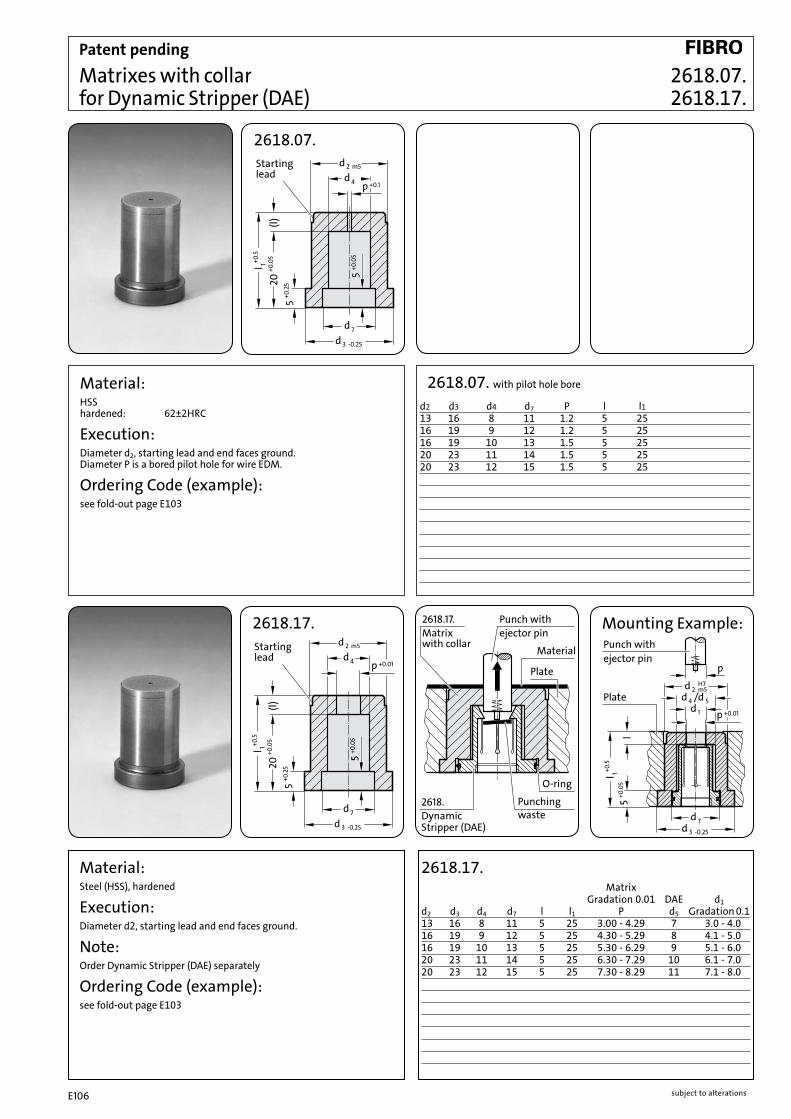
subject to alterationsE106
+0.1d 4
d 2 m5
p
d 7
d 3 -0.25+0
.05
5
+0.2
5
(l)20
+0.0
5l 1+0
.5
5
Startinglead
Material:HSS hardened: 62±2HRC
Execution:Diameter d2, starting lead and end faces ground. Diameter P is a bored pilot hole for wire EDM.
Ordering Code (example):see fold-out page E103
Startinglead
+0.01d 4
d 2 m5
p
+0.0
55
d 7
d 3 -0.25
+0.2
5
(l)20
+0.0
5l 1+0
.5
5
l
+0.01
p
d 7d 3 -0.25
d 2 m5d 4 /d 5
H7
d 1 p
ejector pinPunch with
l 1+0.5
+0.0
55
Plate
2618.
Material
Plate
O-ring
Punchingwaste
2618.17.Matrixwith collar
Punch withejector pin
DynamicStripper (DAE)
Matrixes with collar for Dynamic Stripper (DAE)
2618.17.
Material: Steel (HSS), hardened
Execution:Diameter d2, starting lead and end faces ground.
Note: Order Dynamic Stripper (DAE) separately
Ordering Code (example):see fold-out page E103
Mounting Example:
2618.17. Matrix Gradation 0.01 DAE d1 d2 d3 d4 d7 l l1 P d5 Gradation 0.113 16 8 11 5 25 3.00 - 4.29 7 3.0 - 4.016 19 9 12 5 25 4.30 - 5.29 8 4.1 - 5.016 19 10 13 5 25 5.30 - 6.29 9 5.1 - 6.020 23 11 14 5 25 6.30 - 7.29 10 6.1 - 7.020 23 12 15 5 25 7.30 - 8.29 11 7.1 - 8.0
2618.07. with pilot hole bore
d2 d3 d4 d7 P l l113 16 8 11 1.2 5 2516 19 9 12 1.2 5 2516 19 10 13 1.5 5 2520 23 11 14 1.5 5 2520 23 12 15 1.5 5 25
2618.07. 2618.17.
Patent pending
2618.07.
subject to alterations E107
Precision Retainers for
Ball-Lock Punches
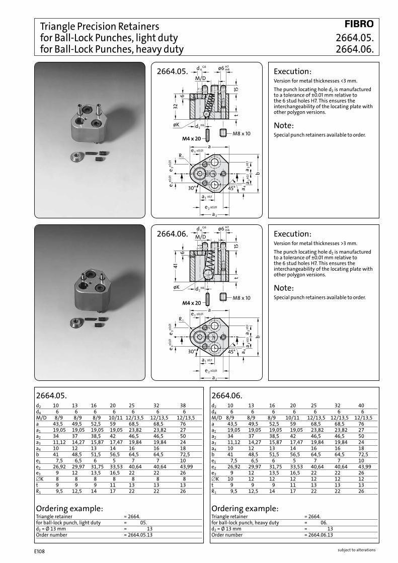
subject to alterationsE108
G6d 4 ø6
øK
H7m6
445°30°
a3a
32
M/D
2
±0,012
±0,1
±0,1
15
d H62
6
t
b
ae
1a ±0,1
1e ±0,01a
3a
M4 x 20M4 x 20M8 x 10
R 1
±0,0
1e 3
±0,0
1e 3
R 1
±0,012e
45°30°
41
M/D15
6
±0,1
a3a
2
a±0
,1
d H62
t
b
a
1a ±0,1
4
1e ±0,01a
3
øK
M4 x 20M4 x 20M8 x 10
G6d 4 ø6 H7m6
±0,0
1e 3
±0,0
1e 3
2664.05.d2 10 13 16 20 25 32 38d4 6 6 6 6 6 6 6M/D 8/9 8/9 8/9 10/11 12/13,5 12/13,5 12/13,5a 43,5 49,5 52,5 59 68,5 68,5 76a1 19,05 19,05 19,05 19,05 23,82 23,82 27a2 34 37 38,5 42 46,5 46,5 50a3 11,12 14,27 15,87 17,47 19,84 19,84 24a4 10 12 13 14 16 16 18b 41 48,5 51,5 56,5 64,5 64,5 72,5e1 7,5 6,5 6 5 7 7 10e2 26,92 29,97 31,75 33,53 40,64 40,64 43,99e3 9 12 13,5 16,5 22 22 26[K 8 8 8 8 8 8 8t 9 9 9 11 13 13 13R1 9,5 12,5 14 17 22 22 26
d2 10 13 16 20 25 32 40d4 6 6 6 6 6 6 6M/D 8/9 8/9 8/9 10/11 12/13,5 12/13,5 12/13,5a 43,5 49,5 52,5 59 68,5 68,5 76a1 19,05 19,05 19,05 19,05 23,82 23,82 27a2 34 37 38,5 42 46,5 46,5 50a3 11,12 14,27 15,87 17,47 19,84 19,84 24a4 10 12 13 14 16 16 18b 41 48,5 51,5 56,5 64,5 64,5 72,5e1 7,5 6,5 6 5 7 7 10e2 26,92 29,97 31,75 33,53 40,64 40,64 43,99e3 9 12 13,5 16,5 22 22 26[K 10 12 12 12 12 12 12t 9 9 9 11 13 13 13R1 9,5 12,5 14 17 22 22 26
Triangle Precision Retainers for Ball-Lock Punches, light duty 2664.05. for Ball-Lock Punches, heavy duty 2664.06.
Execution:Version for metal thicknesses >3 mm.The punch locating hole d2 is manufactured to a tolerance of ±0.01 mm relative to the 6 stud holes H7. This ensures the interchangeability of the locating plate with other polygon versions.
Note:Special punch retainers available to order.
2664.06.
Execution:Version for metal thicknesses <3 mm.The punch locating hole d2 is manufactured to a tolerance of ±0.01 mm relative to the 6 stud holes H7. This ensures the interchangeability of the locating plate with other polygon versions.
Note:Special punch retainers available to order.
2664.05.
2664.06.
Ordering example:Triangle retainer = 2664.for ball-lock punch, light duty = 05.d2 = Ø 13 mm = 13Order number = 2664.05.13
Ordering example:Triangle retainer = 2664.for ball-lock punch, heavy duty = 06.d2 = Ø 13 mm = 13Order number = 2664.06.13

subject to alterations E109
±0,0
1e 3
ø6 H7m6
±0,012e
45°30°
41
M/D
15
6
±0,1
R 1
a3a
2
a±0
,1
d H62
t
b
a
1a ±0,1
4
1e ±0,01a
3
øK
M4 x 20M4 x 20M8 x 10
G6d 4
±0,0
1e 3
4
øK
45°30°
a3a
32
M/D
2
±0,012
±0,1
±0,1
15
d H62
6
t
b
ae
1a ±0,1
1e ±0,01a
3a
M4 x 20M4 x 20M8 x 10
G6d 4 ø6 H7m6
R 1±0
,01
e 3±0
,01
e 3
Execution:Version for metal thicknesses <3 mm.The punch locating hole d2 is manufactured to a tolerance of ±0.01 mm relative to the 6 stud holes H7. This ensures the interchangeability of the locating plate with other polygon versions.
Note:Special punch retainers available to order.
2664.07.
2664.07.d2 6d4 3M/D 6/6,6a 35a1 19,05a2 27a3 11,12a4 6b 37,5e1 9,0e2 23e3 8[K 6t 7R1 8
Ordering example:Triangle retainer = 2664.light duty = 07.d2 = Ø 6 mm = 06Order number = 2664.07.06
2664.10.d2 10 13 16 20 25 32 40d4 6 6 6 6 6 6 6M/D 8/9 8/9 8/9 10/11 12/13,5 12/13,5 12/13,5a 43,5 49,5 52,5 59 68,5 68,5 76a1 19,05 19,05 19,05 19,05 23,82 23,82 27a2 34 37 38,5 42 46,5 46,5 50a3 11,12 14,27 15,87 17,47 19,84 19,84 24a4 10 12 13 14 16 16 18b 41 48,5 51,5 56,5 64,5 64,5 72,5e1 7,5 6,5 6 5 7 7 10e2 26,92 29,97 31,75 33,53 40,64 40,64 43,99e3 9 12 13,5 16,5 22 22 26[K 10 12 12 12 12 12 12t 9 9 9 11 13 13 13R1 9,5 12,5 14 17 22 22 26
Ordering example:Triangle retainer = 2664.heavy duty = 10.d2 = Ø 13 mm = 13Order number = 2664.10.13
Execution:Version for metal thicknesses >3 mm.The punch locating hole d2 is manufactured to a tolerance of ±0.01 mm relative to the 6 stud holes H7. This ensures the interchangeability of the locating plate with other polygon versions.
Note:Special punch retainers available to order.
2664.10.
Triangle Precision Retainers 2664.07. for Ball-Lock Punches, light duty 2664.10. for Ball-Lock Punches, heavy duty

subject to alterationsE110
2664.08.d2 10 13 16 20 25 32d4 6 6 6 6 6 6M/D 8 8 8 10 12 12a 38,5 41,7 43,3 47,5 59,2 59,2a1 19,05 19,05 19,05 19,05 23,82 23,82a2 29 29 29 30 37 37a3 11,12 14,27 15,87 17,47 19,84 19,84b 40,61 47,93 51,59 57,93 70,85 70,85[K 8 8 8 8 8 8t 9 9 9 11 13 13R1 9,5 12,7 14,3 17,5 22,2 22,2R2 9,5 9,5 9,5 11 15 15
d2 10 13 16 20 25 32d4 6 6 6 6 6 6M/D 8 8 8 10 12 12a 38,5 41,7 43,3 47,5 59,2 59,2a1 19,05 19,05 19,05 19,05 23,82 23,82a2 29 29 29 30 37 37a3 11,12 14,27 15,87 17,47 19,84 19,84b 40,61 47,93 51,59 57,93 70,85 70,85[K 10 12 12 12 12 12t 9 9 9 11 13 13R1 9,5 12,7 14,3 17,5 22,2 22,2R2 9,5 9,5 9,5 11 15 15
Triangle Precision Retainers for Ball-Lock Punches, light duty 2664.08. for Ball-Lock Punches, heavy duty 2664.09.
2664.09.
2664.08.
2664.09.
Ordering example:Triangle retainer for ball-lock punch = 2664.light duty = 08.d2 = ∅ 20 mm = 20Order No = 2664.08.20
Ordering example:Triangle retainer for ball-lock punch = 2664.heavy duty = 09.d2 = ∅ 20 mm = 20Order No = 2664.09.20
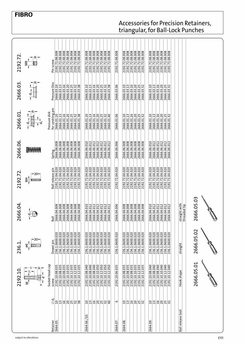
subject to alterations E111
Accessories for Precision Retainers, triangular, for Ball-Lock Punches
Sock
et h
ead
cap
Pres
sure
dis
k
Reta
iner
[
d2
scre
w
Dow
el p
in
Ball
Ball
rele
ase
pin
Sprin
g fo
r cen
trin
g pi
n Pr
essu
re D
isc
Pin
scre
w26
64.0
5.
10
2192
.10.
08.0
35
236.
1.06
00.0
20
2666
.04.
008
2192
.72.
04.0
20
2666
.06.
008
2666
.01.
10
2666
.03.
10
2192
.72.
08.0
08
13
2192
.10.
08.0
35
236.
1.06
00.0
20
2666
.04.
008
2192
.72.
04.0
20
2666
.06.
008
2666
.01.
13
2666
.03.
13
2192
.72.
08.0
08
16
2192
.10.
08.0
35
236.
1.06
00.0
20
2666
.04.
008
2192
.72.
04.0
20
2666
.06.
008
2666
.01.
16
2666
.03.
16
2192
.72.
08.0
08
20
2192
.10.
10.0
35
236.
1.06
00.0
20
2666
.04.
008
2192
.72.
04.0
20
2666
.06.
008
2666
.01.
20
2666
.03.
20
2192
.72.
08.0
08
25
2192
.10.
12.0
35
236.
1.06
00.0
20
2666
.04.
008
2192
.72.
04.0
20
2666
.06.
008
2666
.01.
25
2666
.03.
25
2192
.72.
08.0
08
32
2192
.10.
12.0
35
236.
1.06
00.0
20
2666
.04.
008
2192
.72.
04.0
20
2666
.06.
008
2666
.01.
32
2666
.03.
32
2192
.72.
08.0
08
38
2192
.10.
12.0
35
236.
1.06
00.0
20
2666
.04.
008
2192
.72.
04.0
20
2666
.06.
008
2666
.01.
38
2666
.03.
38
2192
.72.
08.0
08
2664
.06.
/10.
10
21
92.1
0.08
.040
23
6.1.
0600
.020
26
66.0
4.01
0 21
92.7
2.04
.020
26
66.0
6.01
0 26
66.0
1.10
26
66.0
3.10
21
92.7
2.08
.008
13
21
92.1
0.08
.040
23
6.1.
0600
.020
26
66.0
4.01
2 21
92.7
2.04
.020
26
66.0
6.01
2 26
66.0
1.13
26
66.0
3.13
21
92.7
2.08
.008
16
21
92.1
0.08
.040
23
6.1.
0600
.020
26
66.0
4.01
2 21
92.7
2.04
.020
26
66.0
6.01
2 26
66.0
1.16
26
66.0
3.16
21
92.7
2.08
.008
20
21
92.1
0.10
.050
23
6.1.
0600
.020
26
66.0
4.01
2 21
92.7
2.04
.020
26
66.0
6.01
2 26
66.0
1.20
26
66.0
3.20
21
92.7
2.08
.008
25
21
92.1
0.12
.050
23
6.1.
0600
.020
26
66.0
4.01
2 21
92.7
2.04
.020
26
66.0
6.01
2 26
66.0
1.25
26
66.0
3.25
21
92.7
2.08
.008
32
21
92.1
0.12
.050
23
6.1.
0600
.020
26
66.0
4.01
2 21
92.7
2.04
.020
26
66.0
6.01
2 26
66.0
1.32
26
66.0
3.32
21
92.7
2.08
.008
40
21
92.1
0.12
.050
23
6.1.
0600
.020
26
66.0
4.01
2 21
92.7
2.04
.020
26
66.0
6.01
2 26
66.0
1.40
26
66.0
3.38
21
92.7
2.08
.008
2664
.07.
6
21
92.1
0.06
.035
23
6.1.
0600
.020
26
66.0
4.00
6 21
92.7
2.04
.020
26
66.0
6.00
6 26
66.0
1.06
26
66.0
3.06
21
92.7
2.08
.008
2664
.08.
10
21
92.1
0.08
.035
23
6.1.
0600
.020
26
66.0
4.00
8 21
92.7
2.04
.020
26
66.0
6.00
8 26
66.0
1.10
26
66.0
3.10
21
92.7
2.08
.008
13
21
92.1
0.08
.035
23
6.1.
0600
.020
26
66.0
4.00
8 21
92.7
2.04
.020
26
66.0
6.00
8 26
66.0
1.13
26
66.0
3.13
21
92.7
2.08
.008
16
21
92.1
0.08
.035
23
6.1.
0600
.020
26
66.0
4.00
8 21
92.7
2.04
.020
26
66.0
6.00
8 26
66.0
1.16
26
66.0
3.16
21
92.7
2.08
.008
20
21
92.1
0.10
.035
23
6.1.
0600
.020
26
66.0
4.00
8 21
92.7
2.04
.020
26
66.0
6.00
8 26
66.0
1.20
26
66.0
3.20
21
92.7
2.08
.008
25
21
92.1
0.12
.035
23
6.1.
0600
.020
26
66.0
4.00
8 21
92.7
2.04
.020
26
66.0
6.00
8 26
66.0
1.25
26
66.0
3.25
21
92.7
2.08
.008
32
21
92.1
0.12
.035
23
6.1.
0600
.020
26
66.0
4.00
8 21
92.7
2.04
.020
26
66.0
6.00
8 26
66.0
1.32
26
66.0
3.32
21
92.7
2.08
.008
2664
.09.
10
21
92.1
0.08
.040
23
6.1.
0600
.020
26
66.0
4.01
0 21
92.7
2.04
.020
26
66.0
6.01
0 26
66.0
1.10
26
66.0
3.10
21
92.7
2.08
.008
13
21
92.1
0.08
.040
23
6.1.
0600
.020
26
66.0
4.01
2 21
92.7
2.04
.020
26
66.0
6.01
2 26
66.0
1.13
26
66.0
3.13
21
92.7
2.08
.008
16
21
92.1
0.08
.040
23
6.1.
0600
.020
26
66.0
4.01
2 21
92.7
2.04
.020
26
66.0
6.01
2 26
66.0
1.16
26
66.0
3.16
21
92.7
2.08
.008
20
21
92.1
0.10
.040
23
6.1.
0600
.020
26
66.0
4.01
2 21
92.7
2.04
.020
26
66.0
6.01
2 26
66.0
1.20
26
66.0
3.20
21
92.7
2.08
.008
25
21
92.1
0.12
.040
23
6.1.
0600
.020
26
66.0
4.01
2 21
92.7
2.04
.020
26
66.0
6.01
2 26
66.0
1.25
26
66.0
3.25
21
92.7
2.08
.008
32
21
92.1
0.12
.040
23
6.1.
0600
.020
26
66.0
4.01
2 21
92.7
2.04
.020
26
66.0
6.01
2 26
66.0
1.32
26
66.0
3.32
21
92.7
2.08
.008
Ball
rele
ase
tool
Hoo
k sh
ape
stra
ight
st
raig
ht w
ith
th
read
ed ti
p
2192
.72.
2666
.03.
2666
.01.
2666
.06.
2192
.72.
2666
.04.
236.
1.21
92.1
0.
2666
.05.
0326
66.0
5.02
2666
.05.
01

subject to alterationsE112
2661.08.d2 d5 M/D a a1, e t 6 8 8/9 45 13 910131620 10 10/11 56 16 1125 12/13,5 63 20 13
10 8 8/9 45 11 15 28 1 9131620 10 10/11 56 17 18 32 5 1125
Execution:The centres of the pinholes d5 are the reference points for the position of the punch bore. The dimensions e and e1 have a tolerance of ±0,005 mm. The square ball-lock retainers are interchangeable. The order must specify position 1 or 2 for the locking ball. Ball channel horizontal = 1 Ball channel vertical = 2
Note:Supplied with dowel pins and screws DIN EN ISO 4762.
Execution:The centres of the pinholes d5 are the reference points for the position of the punch bore. The e-dimensions have a tolerance of ± 0,005 mm. The square ball-lock retainers are interchangeable.
Note:Supplied with dowel pins and screws DIN EN ISO 4762.
2661.08.
Ordering code (example):Square Retainer = 2661.for Ball-Lock Punch = 2661.08.d2 = Ø 20 mm = 2661.07.20Order No = 2661.08.20
Ordering code (example):Square Retainer = 2661.for Ball-Lock Punch = 2661.07.d2 = Ø 20 mm = 2661.07.20.Vertical ball race = 2661.07.20.2Order No = 2661.07.20.2
2661.07. d2 d5 M/D a a2 b2 e e1 t
Square Precision Retainers 2661.07. for Ball-Lock Punches, light duty 2661.08.
2661.07.
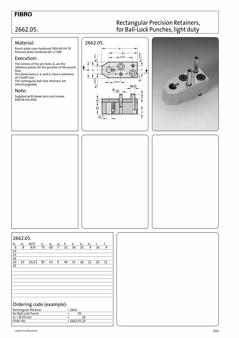
subject to alterations E113
2662.05.d2 d5 M/D a a3 a1 b e e1 e2 c t 6 8 8/9 75 60 7 32 50 25 9 16 910131620 10 10/11 85 63 9 40 53 28 11 20 1125
Material:Punch plate case-hardened 740± 40 HV 10 Pressure plate hardened 60 +2 HRC
Execution:The centres of the pin holes d5 are the reference points for the position of the punch bore. The dimensions e, e1 and e2 have a tolerance of ± 0,005 mm. The rectangular ball-lock retainers are interchangeable.
Note:Supplied with dowel pins and screws DIN EN ISO 4762.
2662.05.
Ordering code (example):Rectangular Retainer = 2662.for Ball-Lock Punch = 2662.05.d2 = Ø 20 mm = 2662.05.20Order No = 2662.05.20
Rectangular Precision Retainers, 2662.05. for Ball-Lock Punches, light duty

subject to alterationsE114
l 1±0,13
-0,0
80
4,5
d 2
d 2
d 4±0,13
d 3±0,005
2668.2./2668.3. 2668.2. Cutting punch-∅ Order code "d2" d3 d4 l12668.2.06 6 12 14.6 25.72668.2.10 10 14 16.6 25.72668.2.13 13 14 16.6 25.72668.2.16 16 14 16.6 25.72668.2.20 20 16 18.6 25.72668.2.25 25 16 18.6 25.72668.2.32 32 16 18.6 25.72668.2.38 38 16 18.6 25.7
2666.05.02 Ball release tool, straight
2668.3. Cutting punch-∅ Order code "d2" d3 d4 l12668.3.10 10 16 19.6 34.72668.3.13 13 20 24.6 34.72668.3.16 16 20 24.6 34.72668.3.20 20 20 24.6 34.72668.3.25 25 20 24.6 34.72668.3.32 32 20 24.6 34.72668.3.40 40 20 24.6 34.7
2666.05.02 Ball release tool, straight
e
b+0,025
Retainer forBall-Lock Punches
Pressure plate
+0,005+0,010a
+0,008+0,015*a
+0,13
4,55
+0,75d
+0,025c
Mounting dimensions for 2668.2. / 2668.3.Order-No. a b c d e2668.2.06 6 6.5 12.013 15.0 25.72668.2.10 10 9.0 14.013 17.0 25.72668.2.13 13 10.5 14.013 17.0 25.72668.2.16 16 12.0 14.013 17.0 25.72668.2.20 20 14.0 16.013 19.0 25.72668.2.25 25 16.5 16.013 19.0 25.72668.2.32 *32 20.0 16.013 19.0 25.72668.2.38 *38 23.0 16.013 19.0 25.7
2668.3.10 10 10.0 16.013 20.0 34.72668.3.13 13 11.5 20.013 25.0 34.72668.3.16 16 13.0 20.013 25.0 34.72668.3.20 20 15.0 20.013 25.0 34.72668.3.25 25 17.5 20.013 25.0 34.72668.3.32 *32 21.0 20.013 25.0 34.72668.3.40 *40 25.0 20.013 25.0 34.7
Typical Application:
Mounting Example:
ACCU-LOCK Fixture Device for Ball-Lock Punches light duty heavy duty
2668.2. 2668.3.

subject to alterations E115
Precision Retainers ISO

subject to alterationsE116
1e ±0,01
d m6ø6
45°30°
3a
M/D
25
3
b
±0,2
2a±0,01e 2
1a ±0,2a 4
a
15
d G52
5+0,0
5
a 36
t±0
,2
R 1
±0,0
1e 3
±0,0
1e 3
Pressure disk2665.01.
e
m6ø6
b 4+0
,02
45°30°e 3
a3a
25
M/D
2
a
±0,2
±0,2
15
d G52
5+0,0
5
6t
b 3 b
±0,0
1
a
1a ±0,24
1e ±0,01a
3
±0,01e 2
R 1
3±0
,01
Pressure disk2665.01.
2664.02.
Triangle Precision Retainers, for round Punches, ISO 8020 2664.02. for Profile Punches, ISO 8020 2664.04.
Execution:The centres of the pinholes d5 are the reference points for the position of the punch bore. The dimensions e1, e2 and e3 have a tolerance of ± 0.01 mm. The triangle retainers are interchangeable.
Note:Pressure plate 2665.01 to be ordered separately for the receiving punch plate.
2664.02.d2 10 13 16 20 25 32d3 14 17 20 24 29 36M/D 8/9 8/9 8/9 10/11 12/13,5 12/13,5a 43,5 49,5 52,5 59 68,5 68,5a1 19,05 19,05 19,05 19,05 23,82 23,82a2 34 37 38,5 42 46,5 46,5a3 11,12 14,27 15,87 17,47 19,84 19,84a4 10 12 13 14 16 16b 41,0 48,5 51,5 56,5 64,5 64,5e1 7,5 6,5 6 5 7 7e2 26,92 29,97 31,75 33,53 40,64 40,64e3 9 12 13,5 16,5 22 22t 9 9 9 11 13 13R1 9,5 12,5 14 17 22 22
Execution:The centres of the pinholes d5 are the reference points for the position of the punch bore. The dimensions e1, e2 and e3 have a tolerance of ± 0.01 mm. The triangle retainers are interchangeable.
Note:Pressure plate 2665.01 to be ordered separately for the receiving punch plate.
2664.04.
2664.04.d2 10 13 16 20 25 32M/D 8/9 8/9 8/9 10/11 12/13,5 12/13,5a 43,5 49,5 52,5 59 68,5 68,5a1 19,05 19,05 19,05 19,05 23,82 23,82a2 34 37 38,5 42 46,5 46,5a3 11,12 14,27 15,87 17,47 19,84 19,84a4 10 12 13 14 16 16b 41,0 48,5 51,5 56,5 64,5 64,5b3 12 15 18 23 28 35b4 5 6,5 8 10 12,5 16e1 7,5 6,5 6 5 7 7e2 26,92 29,97 31,75 33,53 40,64 40,64e3 9 12 13,5 16,5 22 22t 9 9 9 11 13 13R1 9,5 12,5 14 17 22 22
Ordering example:Triangle retainer = 2664.for round Punch, ISO 8020 = 2664.02.d2 = [ 13 mm = 2664.02.13Order number = 2664.02.13
Ordering example:Triangle retainer = 2664.for Profile Punch, ISO 8020 = 2664.04.d2 = [13 mm = 2664.04.13Order number = 2664.04.13

subject to alterations E117
Accessories for Precision Retainers, triangular, for Punches, to ISO 8020
Socket head cap Retainer Ø d2 screw Dowel pin Pin screw Pressure plate2664.02./04. 10 2192.10.08.035 236.1.0600.020 2192.72.08.008 2665.01.10 13 2192.10.08.035 236.1.0600.020 2192.72.08.008 2665.01.13 16 2192.10.08.035 236.1.0600.020 2192.72.08.008 2665.01.16 20 2192.10.10.035 236.1.0600.020 2192.72.08.008 2665.01.20 25 2192.10.12.035 236.1.0600.020 2192.72.08.008 2665.01.25 32 2192.10.12.035 236.1.0600.020 2192.72.08.008 2665.01.32
ø7
2e
±0,1
e 3
ø7
45°30°
øD ø7
øD
R 1
a
a
b
a
4
1e a
3a 31a±0
,1e 3
ø7
6
2192.10. 2192.72. 2665.01.236.1.

subject to alterationsE118
6 10 8 8/9 45 13 15,5 9 8 1210 1413 1716 2020 25 10 10/11 56 16 19 1125 30 12/13,5 63 20 22,5 13
6 10 8 8/9 45 13 15,5 8 9 8 12 1010 14 1213 17 1516 20 1820 25 10 10/11 56 16 19 22,5 1125 30 12/13,5 63 20 22,5 27,5 13
Ordering code (example):Square Retainer = 2661.for punch to ISO 8020 = 2661.02.d2 = [ 20 mm = 2661.02.20Order No = 2661.02.20
2661.02.d2 d3 d5 M/D a a1, e e1 b3 t
Ordering code (example):Square Retainer = 2661.for punch to ISO 8020 = 2661.01.d2 = [ 13 mm = 2661.01.13Order No = 2661.01.13
2661.01.d2 d3 d5 M/D a a1, e e1 t
Square Precision Retainers 2661.01. for Punches to ISO 8020 2661.02.
2661.01. Execution:The centres of the pinholes d5 are the reference points for the position of the punch bore. The dimensions e and e1 have a tolerance of ± 0,005 mm. The square retainers are interchangeable.
Note:Supplied with dowel pins and screws DIN EN ISO 4762.
2661.02. Execution:The centres of the pinholes d5 are the reference points for the position of the punch bore. The dimensions e and e1 have a tolerance of ± 0,005 mm. The square retainers are interchangeable.
Note:Supplied with dowel pins and screws DIN EN ISO 4762.
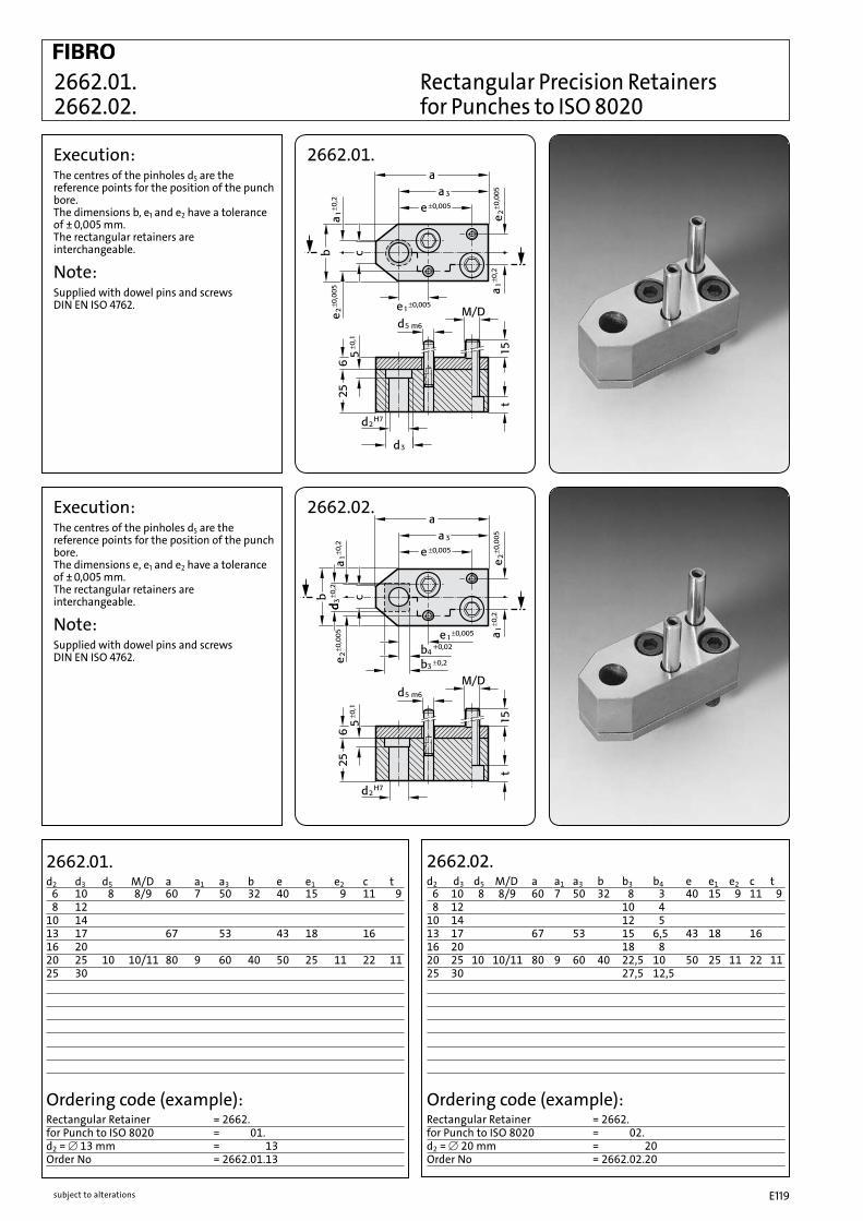
subject to alterations E119
6 10 8 8/9 60 7 50 32 8 3 40 15 9 11 9 8 12 10 410 14 12 513 17 67 53 15 6,5 43 18 1616 20 18 820 25 10 10/11 80 9 60 40 22,5 10 50 25 11 22 1125 30 27,5 12,5
6 10 8 8/9 60 7 50 32 40 15 9 11 9 8 1210 1413 17 67 53 43 18 1616 2020 25 10 10/11 80 9 60 40 50 25 11 22 1125 30
Ordering code (example):Rectangular Retainer = 2662.for Punch to ISO 8020 = 2662.01.d2 = [ 13 mm = 2662.01.13Order No = 2662.01.13
Ordering code (example):Rectangular Retainer = 2662.for Punch to ISO 8020 = 2662.02.d2 = [ 20 mm = 2662.02.20Order No = 2662.02.20
2662.01.d2 d3 d5 M/D a a1 a3 b e e1 e2 c t
2662.02.d2 d3 d5 M/D a a1 a3 b b3 b4 e e1 e2 c t
2662.01. Rectangular Precision Retainers 2662.02. for Punches to ISO 8020
2662.01.Execution:The centres of the pinholes d5 are the reference points for the position of the punch bore. The dimensions b, e1 and e2 have a tolerance of ± 0,005 mm. The rectangular retainers are interchangeable.
Note:Supplied with dowel pins and screws DIN EN ISO 4762.
2662.02.Execution:The centres of the pinholes d5 are the reference points for the position of the punch bore. The dimensions e, e1 and e2 have a tolerance of ± 0,005 mm. The rectangular retainers are interchangeable.
Note:Supplied with dowel pins and screws DIN EN ISO 4762.

subject to alterationsE120

subject to alterations E121
Precision Retainers VDI

subject to alterationsE122
Square Precision Retainers 2661.03. for round Punches to VDI 3374 2661.04.
Execution:The centres of the pinholes d5 are the reference points for the position of the punch bore. The e-dimensions have a tolerance of ± 0,005 mm. The square retainers are interchangeable.
Note:Supplied with dowel pins and screws DIN EN ISO 4762.
2661.04.
10 14 8 8/ 9 45 13 913 1716 2020 25 10 10/11 56 16 1125 30 12/13,5 63 20 1332 37
Ordering code (example):Square retainer = 2661.for round Punch to VDI 3374 = 2661.04.d2 = [ 16 mm = 2661.04.16Order No = 2661.04.16
Execution:The centres of the pinholes d5 are the reference points for the position of the punch bore. The e-dimensions have a tolerance of ± 0,005 mm. The square retainers are interchangeable.
Note:Supplied with dowel pins and screws DIN EN ISO 4762.
2661.03.
10 14 8 8/ 9 45 11 15 28 1 913 1716 2020 25 10 10/11 56 17 18 32 5 1125 30
Ordering code (example):Square retainer = 2661.for round Punch to VDI 3374 = 2661.03.d2 = [ 10 mm = 2661.03.10Order No = 2661.03.10
2661.04.d2 d3 d5 M/D a a1, e t
2661.03.d2 d3 d5 M/D a a2 b2 e e1 t

subject to alterations E123
10 14 8 8/ 9 45 13 12 5 913 17 15 6,516 20 18 820 25 10 10/11 56 16 22,5 10 1125 30 12/13,5 63 20 27,5 12,5
10 14 8 8/ 9 45 11 15 28 1 5 913 17 6,516 20 820 25 10 10/11 56 17 18 32 5 10 1125 30 12,5
Ordering code (example):Square retainer = 2661.for profile punch to VDI 3374 = 2662.05.d2 = [ 13 mm = 2662.05.13Order No = 2662.05.13
2661.05.d2 d3 d5 M/D a a2 a1 e e1 b4 t
Ordering code (example):Square retainer = 2661.for profile punch to VDI 3374 = 2661.06.d2 = [ 20 mm = 2661.06.20Order No = 2661.06.20
2661.06. d2 d3 d5 M/D a a1, e b3 b4 t
2661.05 Square Precision Retainers 2661.06. for Profile Punches to VDI 3374
2661.05.Execution:The centres of the pin holes d5 are the reference points for the position of the punch bore. The e-dimensions have a tolerance of ± 0,005 mm. The square retainers are interchangeable.
Note:Supplied with dowel pins and screws DIN EN ISO 4762.
2661.06.Execution:The centres of the pin holes d5 are the reference points for the position of the punch bore. The e-dimensions have a tolerance of ± 0,005 mm. The square retainers are interchangeable.
Note:Supplied with dowel pins and screws DIN EN ISO 4762.
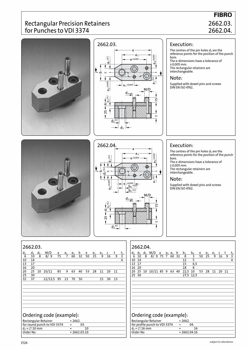
subject to alterationsE124
6 10 8 8/ 9 75 7 60 32 8 3 50 25 9 16 9 310 14 12 5 413 17 15 6,516 20 18 820 25 10 10/11 85 9 63 40 22,5 10 53 28 11 20 1125 30 27,5 12,5
6 10 8 8/ 9 75 7 60 32 50 25 9 16 9 310 14 413 1716 2020 25 10 10/11 85 9 63 40 53 28 11 20 1125 3032 37 12/13,5 95 13 70 50 15 30 13
Ordering code (example):Rectangular Retainer = 2662.for profile punch to VDI 3374 = 2662.04.d2 = [ 16 mm = 2662.04.16Order No = 2662.04.16
Ordering code (example):Rectangular Retainer = 2662.for round punch to VDI 3374 = 2662.03.d2 = [ 10 mm = 2662.03.10Order No = 2662.03.10
2662.04.d2 d3 d5 M/D a a1 a3 b b3 b4 e e1 e2 c t t1
2662.03.d2 d3 d5 M/D a a1 a3 b e e1 e2 c t t1
Rectangular Precision Retainers 2662.03. for Punches to VDI 3374 2662.04.
Execution:The centres of the pin holes d5 are the reference points for the position of the punch bore. The e-dimensions have a tolerance of ± 0,005 mm. The rectangular retainers are interchangeable.
Note:Supplied with dowel pins and screws DIN EN ISO 4762.
2662.04.
Execution:The centres of the pin holes d5 are the reference points for the position of the punch bore. The e-dimensions have a tolerance of ± 0,005 mm. The rectangular retainers are interchangeable.
Note:Supplied with dowel pins and screws DIN EN ISO 4762.
2662.03.

subject to alterations E125
Accessories

subject to alterationsE126
Stripping units 2431.7.
2431.7.
Installation example:Material:FIBROFLEX® 95 Shore A
Note:Stripping units can be used for retainers 2664.02./.04./.05./.06.
2431.7. l
d2 d1 d3 d4 d5 max. b 35 43 53 63 7310 18 21 3 22 6 V V V V 13 23 26 3 26,5 6 V V V V V16 30 33 3 34 6 V V V V V20 33 36 3 38 7 V V V V V25 40 43 3 47,6 7 V V V V V32 50 54 4 57,9 7 V V V V V38 60 64 4 69,6 8 V V V V40 60 64 4 69,6 8 V V V V
Stripping forces (N)* Spring travel 3 mm 6 mm 9 mm 3 mm 6 mm 9 mm 3 mm 6 mm 9 mm 3 mm 6 mm 9 mm 3 mm 6 mm 9 mmd2 Length 35 35 35 43 43 43 53 53 53 63 63 63 73 73 7310 1300 ** ** 01000 01700 ** 0900 01400 ** 0700 01200 01600 — — —13 2100 ** ** 01700 02700 ** 1400 02200 ** 1200 01900 02400 1000 1600 0 200016 3000 ** ** 02500 04000 ** 2000 03200 ** 1700 02700 03500 1500 2400 0 300020 3500 ** ** 02900 04700 ** 2400 03800 ** 2000 03200 04100 1700 2700 0 360025 5400 ** ** 04400 07100 ** 3600 05800 ** 3000 04900 06300 2600 4200 0 550032 8400 ** ** 06800 10900 ** 5500 08800 ** 4700 07500 09700 4000 6400 0 840038 — — — — — ** 7000 10400 ** 6100 9200 12300 5000 7600 1010040 — — — 10400 16600 ** 8500 13600 ** 7000 11300 14800 6000 9800 127000
Ordering example:Stripping unit = 2431.7.d2 = 10 mm = 2431.7.10.l = 53 mm = 2431.7.10.53Order number = 2431.7.10.53
Stripping unit lenght ld2 35 43 53 63 7310 • • • • 13 • • • • •16 • • • • •20 • • • • •25 • • • • •32 • • • • •38 • • • •40 • • • • Punch lengths in useBall-lock punch, light duty 63 71 80 090 100Ball-lock punch, heavy duty 71 80 90 100 110Precision punch ISO 8020 – 71 80 090 100
* values for the stripping force are dependent on a number of parameters (e.g. lubricant, temperature etc.) and may vary from those given here.
** max spring travel should not exceed 15% of the length

subject to alterations E127
2667. Stripping unit mountings
2667.1.
Socket head cap screw M�x������.��.��.���
2667.2.
Installation example:
2667.1/2.d2 d1 d3 R1 a10 18 21 13 2813 23 26 15,5 3116 30 33 18 32,920 33 36 20,5 34,825 40 43 24 39,832 50 54 31 41,338 60 64 36 4440 60 64 36 44
Mounting on retainer for ball-lock punch, multi-sided
Mounting on precision retainer, multi-sided ISO 8020
Note:Pressure plate, mounting plate and screw must all be ordered individually.
Ordering example:Stripping unit mountings = 2667.Type = 2667.1.d2 = 10mm = 2667.1.010Order number = 2667.1.010

subject to alterationsE128
Special Punches, Custom made High-Precision Special Parts to Customer´s Drawings
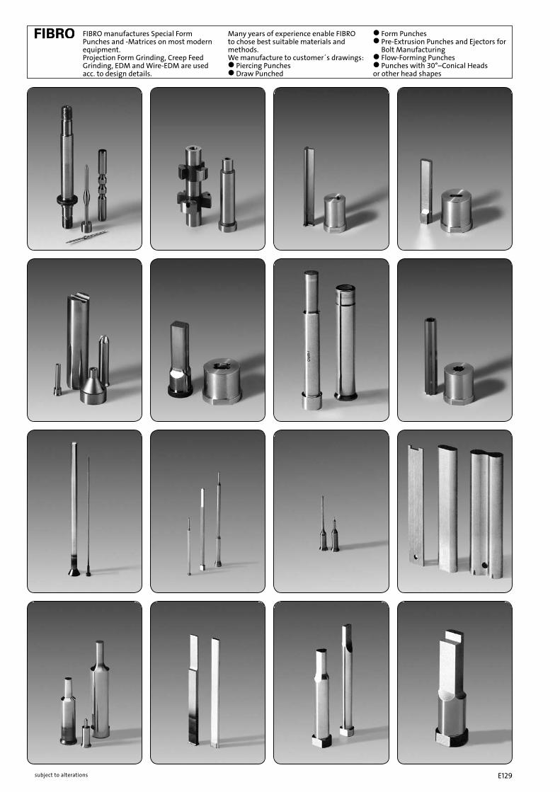
subject to alterations E129
FIBRO manufactures Special Form Punches and -Matrices on most modern equipment. Projection Form Grinding, Creep Feed Grinding, EDM and Wire-EDM are used acc. to design details.
Many years of experience enable FIBRO to chose best suitable materials and methods. We manufacture to customer´s drawings: ● Piercing Punches ● Draw Punched
● Form Punches ● Pre-Extrusion Punches and Ejectors for Bolt Manufacturing ● Flow-Forming Punches ● Punches with 30°–Conical Heads or other head shapes
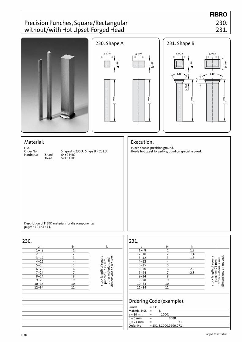
subject to alterationsE130
Precision Punches, Square/Rectangular 230. without/with Hot Upset-Forged Head 231.
230. Shape A 231. Shape B
230. a b l1 1– 8 1 2–10 2 3–12 3 4–12 4 5–15 5 6–20 6 7–24 7 8–24 8 9–28 9 10–34 10 12–34 12
Material: HSSOrder No: Shape A = 230.3., Shape B = 231.3.Hardness: Shank 64±2 HRC Head 52±3 HRC
Execution: Punch shanks precision ground. Heads hot upset forged – ground on special request.
Description of FIBRO materials for die components: pages E 10 and E 11.
stoc
k le
ngth
of s
quar
e
punc
hes:
73,
5 m
m;
othe
r mat
eria
ls a
nd
dim
ensi
ons o
n re
ques
t.
231. a b h l1 1– 8 1 1,2 2–10 2 1,4 3–12 3 1,8 4–12 4 5–15 5 6–20 6 2,0 7–24 7 2,8 8–24 8 9–28 9 10–34 10 12–34 12
stoc
k le
ngth
of s
quar
e
punc
hes:
71
mm
ot
her m
ater
ials
and
di
men
sion
s on
requ
est.
Ordering Code (example):Punch = 231.2.1000.0600.071Material HSS = 231.3.1000.0600.071a = 10 mm = 231.2.1000.0600.071b = 6 mm = 231.2.1000.0600.071l1 = 71 mm = 231.2.1000.0600.071Order No = 231.3.1000.0600.071

subject to alterations E131
Material: steel hardenedOrder No: 236.1.Hardness: 60±2 HRC
Execution:Hardened and ground to finest finish. FIBRO Dowel Pins are manufactured with the exacting requirements of high class diemaking in mind. Whereas DIN EN ISO 8735 stipulates ISO Class 6 for dowels, we produce our pins to m5.FIBRO Dowels with internal extracting thread deviate from DIN in that they are case-hardened and that a smaller thread is used. This increases the crossection around the threaded hole and thus prevents breaking.
236.001FIBROZIPPExtraction tool for the fast and convenient removal of dowels with internal extracting thread – also for shafts, plugs and other machine components. The tool comes with interchangeable adaptors and screws, to fit all threads from M3 to M16.
Precision Dowel Pins (Parallel) with Internal Extracting Thread 236.1. similar to DIN EN ISO 8735/ISO 8735 236.001 Dowel Pin Extractor “FIBROZIPP”
236.1.
Ordering Code (example):Dowel Pin with Extracting Thread = 236.1.d1 = [ 12 mm = 236.1.1200.l1 = 100 mm = 236.1.1200.100Order No = 236.1.1200.100
236.1. d1 6 8 10 12 14 16 20 25 d2 M 4 M 5 M 6 M 6 M 8 M 8 M 10 M 16 t1 6 8 10 10 12 12 16 24 l2 2,1 2,6 3 3,8 4 4,7 6 6 r 6 8 10 12 14 16 20 25 l1 16 ● 18 ● 20 ● ● 24 ● ● ● 28 ● ● ● ● 32 ● ● ● ● ● ● 36 ● ● ● ● ● ● ● 40 ● ● ● ● ● ● ● 45 ● ● ● ● ● ● ● ● 50 ● ● ● ● ● ● ● ● 55 ● ● ● ● ● ● ● ● 60 ● ● ● ● ● ● ● ● 70 ● ● ● ● ● ● ● 80 ● ● ● ● ● ● ● 90 ● ● ● ● ● ● ● 100 ● ● ● ● ● ● ● 120 ● ● ● ● ●

subject to alterationsE132
236.001 FIBROZIPPExtraction tool for the fast and convenient removal of dowels with internal extracting thread – also for shafts, plugs and other machine components. The tool comes with interchangeable adaptors and screws, to fit all threads from M3 to M16.
Precision Dowel Pins (Parallel) with Internal Extracting Thread similar to DIN EN ISO 8735/ISO 8735 2361.1. Dowel Pin Extractor "FIBROZIPP" 236.001
2361.1.
Material: steel hardenedOrder No: 2361.1.Hardness: 60±2 HRC
Execution:Hardened and ground to finest finish. FIBRO Dowel Pins are manufactured with the exacting requirements of high class diemaking in mind.
Ordering Code (example):Dowel Pin = 2361.1.d1 = [ 10 mm = 2361.1.1000.l1 = 45 mm = 2361.1.1000.045Order No = 2361.1.1000.045
2361.1. d1 4 5 6 8 10 12 14 16 20 d2 M 3 M 3 M 4 M 5 M 6 M 6 M 8 M 8 M 10 t1 4,5 6 6 8 10 10 12 12 16 l2 1,3 1,7 2,1 2,6 3 3,8 4 4,7 6 r 4 5 6 8 10 12 14 16 20 l1 08 ● 10 ● ● 12 ● ● ● 14 ● ● ● 16 ● ● ● ● ● 18 ● ● ● ● ● 20 ● ● ● ● ● ● 22 ● ● 24 ● ● ● ● ● ● 26 ● ● 28 ● ● ● ● ● ● ● 30 ● ● ● ● ● ● 32 ● ● ● ● ● ● ● ● 36 ● ● ● ● ● ● ● ● ● 40 ● ● ● ● ● ● ● ● ● 45 ● ● ● ● ● ● ● ● 50 ● ● ● ● ● ● ● ● ● 55 ● ● ● ● ● ● ● ● 60 ● ● ● ● ● ● ● ● 70 ● ● ● ● ● ● ● 80 ● ● ● ● ● ● ● 90 ● ● ● ● ● ● 100 ● ● ● ● ● ● 120 ● ● ● ● ● ●

subject to alterations E133
265.1. d1 d D D1 l1 l2 6 7 10 12 25 12 8 9 12 14 30 16 10 11 16 18 36 20
2650.1. d1 d D D1H6 l1 l2 6 7 10 10 25 12 8 9 12 12 30 16 10 11 16 16 36 20
265.1.for epoxy bonding
Ordering Code (example): One Dowel Liner Bush – only – Dowel Liner Bush = 265. analogous 2650.Material: Tool Steel = 265.1.d1 = [ 8,0 mm = 265.1.0800.Quantity: one = 265.1.0800.1Order No = 265.1.0800.1
Ordering Code (example): One Dowel Liner Bush + Matching Dowel Dowel Liner Bush = 265. analogous 2650.Material: Tool Steel = 265.1.d1 = [ 8,0 mm = 265.1.0800.Quantity: one = 265.1.0800.1.Dowel: length= 40 mm = 265.1.0800.1.040Order No = 265.1.0800.1.040
Ordering Code (example): Two Dowel Liner Bushes + one Dowel Dowel Liner Bush = 265. analogous 2650.Material: Tool Steel = 265.1.d1 = [ 8,0 mm = 265.1.0800.Quantity: two = 265.1.0800.2.Dowel: length= 50 mm = 265.1.0800.2.050Order No = 265.1.0800.2.050
Material: Tool Steel, hardened Hardness 54±2 HRC
2650.1.for push fit
Material: Tool Steel, hardened Hardness 54±2 HRC
Epoxy-BondingFIBRO Hardened Dowel Liner Bushes solve the problem of wear on soft parts subjected to frequent dismantling. Held in perfect co-axial alignment by the close-fitting dowel, they are epoxy-bonded into rough-drilled clearance holes. In hardened parts, Dowel Liner Bushes help to overcome the ever-present toolroom problem of heat treatment distortion – insurmountable exept where jig grinding facilities are available and justifiable on cost grounds. Retainer holes for Dowel Liner Bushes should be approximately 2 mm larger in diameter than the bush O.D. – a coarse finish is desirable. Following exact positioning/aligning, FIBROLIT® ZWO or FIBROFIX® SECHS is used for bonding.
Push FitThe position of the bush is given by push fit hole tolerance H 6. The adhesive order no. 281.648 provides optimum bush retention whilst offering the following advantages: – high accuracy and stiffness – no problems to find position when changing bushings.We do not recommend to press fit bushings.
High-Precision Liner Bushes for Dowel Pins, 265.1. for bonding 2650.1. for push fit

subject to alterationsE134
Execution:Hardened and ground to finest finish.FIBRO-Dowel Pins are manufactured with the exacting requirements of high class diemaking in mind. Whereas DIN EN ISO 8734 stipulates ISO Class 6 for dowels, we produce our pins to m5.
Precision Dowel Pins (Parallel) similar to DIN EN ISO 8734/ISO 8734 235.1.
235.1.
Material: steel hardenedOrder No: 235.1.Hardness: 60±2 HRC
235.1. d1 1 1,5 2 2,5 3 4 5 6 8 10 12 14 16 20 l2 0,48 0,62 0,78 0,95 1,1 1,4 1,7 2,1 2,6 3 3,8 3,8 4,7 6 r 1 1,6 2 2,5 3 4 5 6 8 10 12 16 16 20 l1 6 ● ● ● ● ● 8 ● ● ● ● ● ● ● 10 ● ● ● ● ● ● ● ● ● 12 ● ● ● ● ● ● ● ● ● 14 ● ● ● ● ● ● ● ● 16 ● ● ● ● ● ● ● ● ● 18 ● ● ● ● ● ● ● ● 20 ● ● ● ● ● ● ● ● ● 24 ● ● ● ● ● ● ● ● ● 28 ● ● ● ● ● ● ● ● ● 32 ● ● ● ● ● ● ● ● ● 36 ● ● ● ● ● ● ● ● ● ● 40 ● ● ● ● ● ● ● ● ● 45 ● ● ● ● ● ● ● ● ● 50 ● ● ● ● ● ● ● ● 55 ● ● ● ● ● ● ● ● ● 60 ● ● ● ● ● ● ● ● ● 70 ● ● ● ● ● ● ● ● 80 ● ● ● ● ● ● ● ● 90 ● ● ● ● ● ● ● 100 ● ● ● ● ● ● ● 120 ● ● ● ● ● ● 130 ● 140 ● ●
Ordering Code (example):Dowel Pin = 235.1.d1 = [ 10 mm = 235.1.1000.l1 = 80 mm = 235.1.1000.080Order No = 235.1.1000.080

subject to alterations E135
2351.1.
Precision Dowel Pins (Parallel) 2351.1. similar to DIN EN ISO 8734/ISO 8734
Material: steel hardenedOrder No: 2351.1.Hardness: 60±2 HRC
Execution:Hardened and ground to finest finish.FIBRO-Dowel Pins are manufactured with the exacting requirements of high class diemaking in mind.
2351.1. d1 1 1,5 2 2,5 3 4 5 6 8 10 12 14 16 20 l2 0,4 0,5 0,6 0,7 0,8 1 1,2 1,5 1,8 2 2,5 2,5 3 4 r 1 1,6 2 2,5 3 4 5 6 8 10 12 16 16 20 l1 4 ● ● ● 5 ● ● ● ● ● 6 ● ● ● ● ● ● 8 ● ● ● ● ● ● ● ● 10 ● ● ● ● ● ● ● ● 12 ● ● ● ● ● ● ● ● 14 ● ● ● ● ● ● ● ● 16 ● ● ● ● ● ● ● ● ● 18 ● ● ● ● ● ● ● ● 20 ● ● ● ● ● ● ● ● ● ● 22 ● ● ● ● ● ● ● ● ● 24 ● ● ● ● ● ● ● ● ● ● ● ● 26 ● ● ● ● ● ● ● ● ● ● 28 ● ● ● ● ● ● ● ● ● ● ● 30 ● ● ● ● ● ● ● ● ● ● ● 32 ● ● ● ● ● ● ● ● ● ● ● 36 ● ● ● ● ● ● ● ● ● ● 40 ● ● ● ● ● ● ● ● ● ● ● 45 ● ● ● ● ● ● ● ● ● ● 50 ● ● ● ● ● ● ● ● ● ● 55 ● ● ● ● ● ● ● ● 60 ● ● ● ● ● ● ● ● ● ● 70 ● ● ● ● ● ● ● ● ● 80 ● ● ● ● ● ● ● ● ● 90 ● ● ● ● ● ● ● 100 ● ● ● ● ● ● ● 120 ● ● ● ● ● ●
Ordering Code (example):Dowel Pin = 2351.1.[ d1 = 10 mm = 2351.1.1000.l1 = 45 mm = 235.11.1000.045Order No = 2351.1.1000.045

subject to alterationsE136
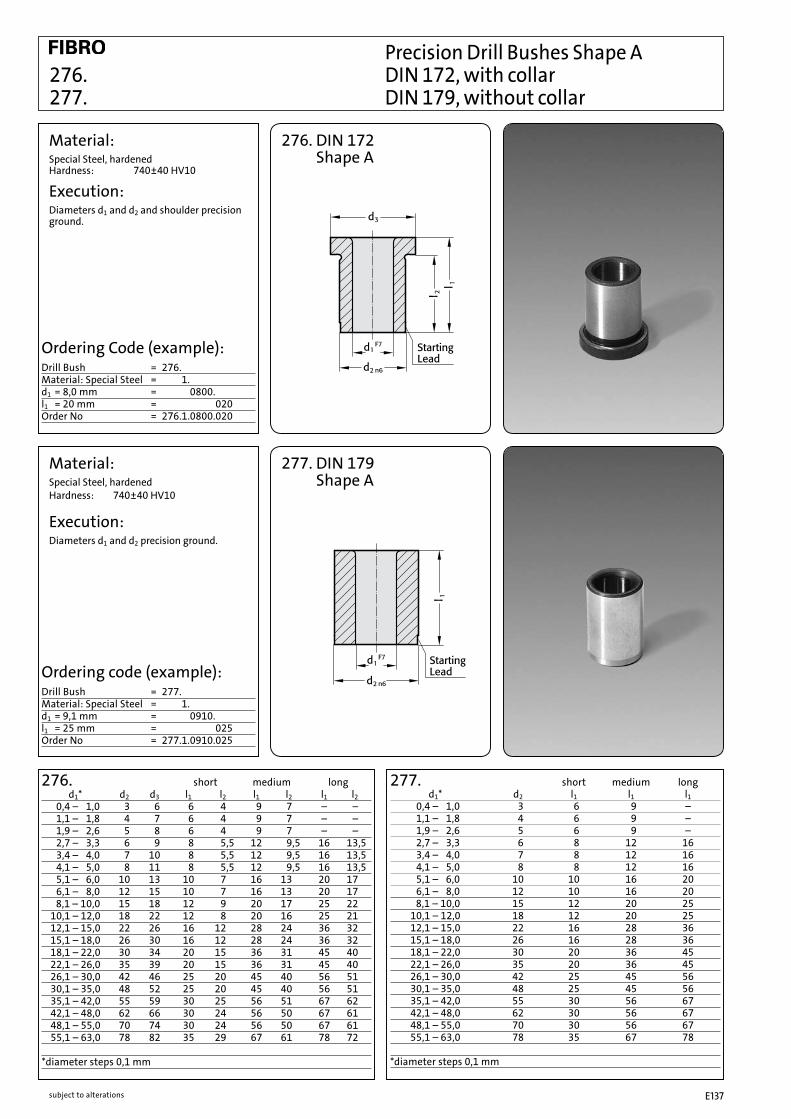
subject to alterations E137
Precision Drill Bushes Shape A 276. DIN 172, with collar 277. DIN 179, without collar
Material:Special Steel, hardened Hardness: 740±40 HV10
Execution:Diameters d1 and d2 and shoulder precision ground.
Ordering Code (example):Drill Bush = 276.Material: Special Steel = 276.1.d1 = 8,0 mm = 276.1.0800.l1 = 20 mm = 276.1.0800.020Order No = 276.1.0800.020
276. DIN 172 Shape A
Material:Special Steel, hardenedHardness: 740±40 HV10
Execution:Diameters d1 and d2 precision ground.
Ordering code (example):Drill Bush = 277.Material: Special Steel = 277.1.d1 = 9,1 mm = 277.1.0910.l1 = 25 mm = 277.1.0910.025Order No = 277.1.0910.025
277. DIN 179 Shape A
276. short medium long d1* d2 d3 l1 l2 l1 l2 l1 l2 0,4 – 1,0 3 6 6 4 9 7 – – 1,1 – 1,8 4 7 6 4 9 7 – – 1,9 – 2,6 5 8 6 4 9 7 – – 2,7 – 3,3 6 9 8 5,5 12 9,5 16 13,5 3,4 – 4,0 7 10 8 5,5 12 9,5 16 13,5 4,1 – 5,0 8 11 8 5,5 12 9,5 16 13,5 5,1 – 6,0 10 13 10 7 16 13 20 17 6,1 – 8,0 12 15 10 7 16 13 20 17 8,1 – 10,0 15 18 12 9 20 17 25 22 10,1 – 12,0 18 22 12 8 20 16 25 21 12,1 – 15,0 22 26 16 12 28 24 36 32 15,1 – 18,0 26 30 16 12 28 24 36 32 18,1 – 22,0 30 34 20 15 36 31 45 40 22,1 – 26,0 35 39 20 15 36 31 45 40 26,1 – 30,0 42 46 25 20 45 40 56 51 30,1 – 35,0 48 52 25 20 45 40 56 51 35,1 – 42,0 55 59 30 25 56 51 67 62 42,1 – 48,0 62 66 30 24 56 50 67 61 48,1 – 55,0 70 74 30 24 56 50 67 61 55,1 – 63,0 78 82 35 29 67 61 78 72 *diameter steps 0,1 mm
277. short medium long d1* d2 l1 l1 l1 0,4 – 1,0 3 6 9 – 1,1 – 1,8 4 6 9 – 1,9 – 2,6 5 6 9 – 2,7 – 3,3 6 8 12 16 3,4 – 4,0 7 8 12 16 4,1 – 5,0 8 8 12 16 5,1 – 6,0 10 10 16 20 6,1 – 8,0 12 10 16 20 8,1 – 10,0 15 12 20 25 10,1 – 12,0 18 12 20 25 12,1 – 15,0 22 16 28 36 15,1 – 18,0 26 16 28 36 18,1 – 22,0 30 20 36 45 22,1 – 26,0 35 20 36 45 26,1 – 30,0 42 25 45 56 30,1 – 35,0 48 25 45 56 35,1 – 42,0 55 30 56 67 42,1 – 48,0 62 30 56 67 48,1 – 55,0 70 30 56 67 55,1 – 63,0 78 35 67 78 *diameter steps 0,1 mm

subject to alterationsE138
240. d1 steps l1 0,30– 1,00 0,01 50 1,01– 3,00 3,01– 6,00 6,01– 10,00 70 10,01– 12,00 12,01– 14,00 14,01– 16,00 16,01– 19,00 19,01– 20,00
Ordering Code (example):Gauge Pin = 240.Class I-Accuracy = 1.d1 = [ 4,04 mm = 0404Order No = 240.1.0404
Order NoSingle Pins: Class I-Accuracy 240.1.
Class II-Accuracy 240.2.Small Set: 91 Gauge Pins from ∅ 1-10 mm
in steps of 0,1 mm, complete in wooden box Class I-Accuracy 240.51. Class II-Accuracy 240.52.
Large Set: 273 Gauge Pins from ∅ 1-10 mm in steps of 0,1 mm, plus one each. 0,01 mm-oversize/undersize pin – complete in wooden box Class I-Accuracy 240.41. Class II-Accuracy 240.42.
Special Sets: supplied to customer’s requirements in respect of assortment and class of accuracy
All Gauge Pins from 3 mm upward are marked with their actual size.
240.
Material:Alloy Tool Steel, hardened and tempered. Age-treated repeatedlyHardness: 60±2HRC
Execution:Precision ground Class I – Accuracy: diameter tolerance ±0,001 Class II – Accuracy: diameter tolerance ±0,002
High-Precision Gauge Pins DIN 2269 240.

subject to alterations E139
High-Precision Gauge Pins DIN 2269 240. Gauge Pin Holders, Wooden Boxes
240. Gauge Pin Holders (with pins) for diameters Order No from 1 – 2 240.45.1 from 2 – 4 240.45.2 from 4 – 6 240.45.3 from 6 – 8 240.45.4 from 8 – 10 240.45.5 Gauge Pin Holders are double-ended, to carry twopins e.g. for go – no go measurements etc.
Wooden with drilled holes, for the safe Order No boxes: and orderly storage of gauge (without pins – each hole marked with pins) the requisite pin size.
Large Set of approx. 270 Pins size: 390 x 250 x 90 mm 240.91.
Small Set of approx. 90 Pins size: 285 x 155 x 90 240.92.
Boxes complete with carrier board inset Class I-Accuracy 1 Class II-Accuracy 2
Ordering code (example):Gauge pin box – approx. 270 pins = 240.91.Class I-Accuracy = 1Order No = 240.91.1

subject to alterationsE140
240.11. High-Precision Gauge Pins with HandleThe Gauge Pins are firmly fixed to the handle. Each Pin is marked with its true diameter.
Single Ø 0,3 – 3,0 mm Order No Gauge In dia. steps of 0.01 mm Pins: Class II-Accuracy 240.11. Class II-Accuracy 240.22.
Assortment: 84 Gauge Pins from 0.3 – 3.0 mm, in dia. steps of 0.1 mm plus one each pin with undersize 0.01 and oversize 0.01 mm (for example 0.29 – 0.30 – 0.31 etc.) Class II-Accuracy 240.31. Class II-Accuracy 240.32.
Special to customer’s specifications Assortments: in respect of class of accuracy
Execution:Wooden boxes for Gauge Pins – with drilled holes in wooden tray insert. Each hole marked with true size of pin. External dimensions: 155x90x285 mm
High Precision Gauge Pins with Handle 240.11./22. High Precision Gauge Pins – Boxed Sets 240.31./32.
Material:Alloy tool steel, hardened and tempered. Repeatedly age-treated. Hardness 60 ± 2 HRC. fine-ground Class II-Accuracy ±0.001 Class II-Accuracy ±0.002 to DIN 2269
Ordering Code (example):Gauge Pin = 240.Class I-Accuracy, with handle = 240.11.d1 = 1,5 mm = 0150Order No = 240.11.0150
240.11.

subject to alterations E141
2282.01.
2282.01.035 B 3,5 2,75 3,2 7,5 3,75 2,7 2,7 3,1 7,5 3,75 31,3 28 74,5 71,5 602282.01.039 B 3,9 3,05 3,4 7,5 3,75 3,0 3,0 3,6 7,5 3,752282.01.042 B 4,2 3,15 3,5 8,5 4,25 3,1 3,1 3,7 8,0 4,02282.01.048 B 4,8 3,85 4,2 9,0 4,50 3,8 3,8 4,5 8,0 4,02282.01.055 B 5,5 4,35 4,8 9,0 4,50 4,3 4,3 5,0 8,0 4,02282.01.063 B 6,3 4,85 5,3 10,5 5,25 4,8 4,8 5,5 10,0 5,0
Nominal diameter Order No = thread size d1
H7 d2 d3h6 d4k6 d5h6 d6H7 d7 d8h6 d9k6 l1 l2 l3 l4 l5
Punching and Embossing Unit with Bottom Die for punched holes 2282.01. and self tapping screws
Material:HSS
Execution: The punching and embossing unit with bottom die consists of:1 x punch die1 x embossing die1 x bottom die
Sheet metal thicknessmax. 0,6 mm = 2282.01.035 = 2282.01.039max. 0,8 mm = 2282.01.042max. 0,9 mm = 2282.01.048max. 1,0 mm = 2282.01.055 = 2282.01.063
2282.01.xxx2282.01.xxx.1 Embossing die 2282.01.xxx.2 Punch die 2282.01.xxx.3 Bottom die
Ordering Code (Example)Punching and embossing unit with bottom die for punched holes = 2282.01.Nominal diameter = thread size (self tapping screw) = B = 3.5 mm = 2282.01.035Order No = 2282.01.035

subject to alterationsE142