a distributed data flow model for …eig.stanford.edu/publications/david_liu/david_dissertation.pdfa...
TRANSCRIPT

A DISTRIBUTED DATA FLOW MODEL FOR COMPOSING SOFTWARE SERVICES
A DISSERTATION
SUBMITTED TO THE DEPARTMENT OF ELECTRICAL ENGINEERING
AND THE COMMITTEE ON GRADUATE STUDIES
OF STANFORD UNIVERSITY
IN PARTIAL FULFILLMENT OF THE REQUIREMENTS
FOR THE DEGREE OF
DOCTOR OF PHILOSOPHY
Wanqian David Liu
June 2003

Copyright by Wanqian David Liu 2003
All Rights Reserved
ii

I certify that I have read this dissertation and that, in my opinion, it is fully adequate in scope and quality as a dissertation for the degree of Doctor of Philosophy.
__________________________________ Gio Wiederhold
(Principal Advisor)
I certify that I have read this dissertation and that, in my opinion, it is fully adequate in scope and quality as a dissertation for the degree of Doctor of Philosophy.
__________________________________ Kincho H. Law (Co-Advisor)
I certify that I have read this dissertation and that, in my opinion, it is fully adequate in scope and quality as a dissertation for the degree of Doctor of Philosophy.
__________________________________ Armando Fox
I certify that I have read this dissertation and that, in my opinion, it is fully adequate in scope and quality as a dissertation for the degree of Doctor of Philosophy.
__________________________________ Ram D. Sriram
Approved for the University Committee on Graduate Studies.
iii
Abstract
This thesis presents a distributed data-flow model for composing autonomous software
services, as might be provided over the web. The autonomous services are linked to form
a data processing system, controlled by one node, which we call the megaservice. The
distributed data-flow model allows direct data exchange among the autonomous services.
This is different from the traditional centralized data-flow model where the megaservice
is the central hub for all the data traffic. A theoretical analysis shows that the distributed
data-flow model has better performance and scalability than the centralized data-flow
model. The distribution of data communications fully utilizes the network capacity
among the autonomous services, and avoids bottlenecks at the megaservice.
A prototype infrastructure for service composition, the Flow-based Infrastructure for
Composing Autonomous Services (FICAS), has been implemented to support the
distributed data-flow model. FICAS is a collection of software modules that support the
construction of autonomous services, facilitate the specification of the megaservice, and
enable the efficient execution of the megaservice. The distribution of data
communications is enabled by a metamodel defined for autonomous services, which
separates the data interchange from the control processing in the services. Autonomous
services conforming to the metamodel can be coordinated by a centralized controller,
while data communications are distributed among the services.
iv
Data transformations and similar computational tasks are often needed to interface
autonomous services. Since in the distributed data-flow model the data do not flow
through the megaservice, such transformations have to be carried out externally. To
achieve that we define mobile classes, dynamic processing routines that can be loaded
onto an autonomous service to prepare data local to the service. By moving
computations closer to data, the amount of data traffic can be significantly reduced for a
megaservice, hence improving the performance of the megaservice.
Based on FICAS, an engineering service infrastructure is constructed for project
management applications in the construction industry. The infrastructure demonstrates
that the distributed data-flow model is suitable for composing large-scale software
services.
v

Acknowledgments
There have been a number of truly exceptional people who contributed to my research
and social life at Stanford University.
I wish to express gratitude to my principal advisor, Gio Wiederhold, for his constant
support. Gio has provided me with the intellectual guidance, while giving me the
freedom to pursue independent research. I am deeply indebted to my co-advisor Kincho
H. Law. His passion for research and his insights in life have made profound influence
on me. I am privileged to have Kincho as a mentor and a friend. I would also like to
thank the other members of my reading committee, Armando Fox and Ram D. Sriram,
for their invaluable comments and advices.
I would like to acknowledge my family, who are more special to me than words can
describe. My parents, Zhongying Wan and Dachun Liu, have guided, supported and
believed in me constantly ever since my first memories. My sister, Weiran Liu, has been
a special friend with whom to share joys and sorrows.
Finally, I am grateful to the members of the Engineering Informatics Group, including
Jun Peng, Jim Cheng, Jerome Lynch, Jie Wang, Chuck Han, Shawn Kerrigan, Gloria
Lau, Charles Heenan, Li Zhang, Bill Labiosa, Yang Wang, Pooja Trivedi, Haoyi Wang,
and Xiaoshan Pan, for helping me with various aspects of my research and life.
vi

I gratefully acknowledge the financial support provided by the Center for Integrated
Facility Engineering at Stanford University, the Air Force (Grant F49620-97-1-0339,
Grant F30602-00-2-0594), and the Product Engineering Program at National Institute of
Standards and Technology.
vii

Table of Contents
Abstract iv
Acknowledgments vi
List of Tables xii
List of Figures xiii
1 Introduction 1
1.1 Overview...........................................................................................................1
1.1.1 Composition of Autonomous Services ....................................................2
1.1.2 Distributed Data-flow Model ..................................................................6
1.2 Related Research...............................................................................................8
1.2.1 Distributed Computing Environment ......................................................8
1.2.2 Common Object Request Broker Architecture......................................10
1.2.3 CHAIMS................................................................................................11
1.2.4 Shared Dataspace...................................................................................12
1.2.5 Web Services .........................................................................................14
1.3 Organization of the Thesis ..............................................................................17
2 Service Composition Infrastructures 19
2.1 Service Integration Models .............................................................................20
2.1.1 Model Classification..............................................................................20
2.1.2 Centralized Control-flow and Centralized Data-flow Model ................22
2.1.3 Distributed Control-flow Models ..........................................................23
viii
2.1.4 Centralized Control-flow and Distributed Data-flow Model ................24
2.2 System Modeling ............................................................................................26
2.3 Aggregated Cost of a Megaservice .................................................................28
2.3.1 Aggregated Cost Definition...................................................................28
2.3.2 Centralized Data-flow Model ................................................................29
2.3.3 Distributed Data-flow Model ................................................................31
2.3.4 Comparison of Centralized and Distributed Data-Flow Models ...........33
2.4 Response Time For Megaservices ..................................................................34
2.4.1 Serialized Invocation of Megaservices..................................................35
2.4.2 Parallel Invocation of Megaservices......................................................41
2.5 Performance Impact of Control-flows ............................................................44
2.6 Summary .........................................................................................................47
3 Autonomous Services 49
3.1 Autonomous Service Metamodel....................................................................50
3.1.1 Hierarchical Model ................................................................................51
3.1.2 Data Model ............................................................................................53
3.1.3 Service Interaction Model .....................................................................57
3.1.3.1 Identification for Autonomous Services..................................57
3.1.3.2 Control-flows and Data-flows .................................................58
3.1.3.3 Events in FICAS......................................................................59
3.1.3.4 Data Container and Data Map .................................................60
3.1.4 Structural Model ....................................................................................62
3.2 Autonomous Service Access Protocol ............................................................65
3.2.1 Initialization and Termination Events ...................................................66
3.2.2 Invocation Events ..................................................................................68
3.2.3 Data-flow Events ...................................................................................70
3.2.4 Auxiliary Events ....................................................................................72
3.3 Autonomous Service Wrapper ........................................................................73
3.4 Summary .........................................................................................................77
ix
4 Buildtime Environment of FICAS 79
4.1 Compositional Specification...........................................................................82
4.1.1 Data Types and Operations....................................................................82
4.1.2 Autonomous Service Statement ............................................................86
4.1.3 Conditional Statements..........................................................................88
4.1.4 Comparison Between CLAS and CLAM ..............................................89
4.2 CLAS Compiler and FICAS Control Sequence..............................................91
4.2.1 Lexical Analysis ....................................................................................92
4.2.2 Syntax Analysis .....................................................................................94
4.2.3 Code Generation....................................................................................96
4.2.4 Example Demonstration ......................................................................100
4.3 Computational Specification.........................................................................102
4.3.1 Constructing Mobile Class ..................................................................102
4.3.2 Mobile Class for Data Processing .......................................................106
4.3.3 Mobile Class for Type Mediation........................................................109
4.3.4 Mobile Class for Extraction Model Mediation....................................111
4.4 Summary .......................................................................................................112
5 Runtime Environment of FICAS 114
5.1 Architecture of the Runtime Environment....................................................115
5.1.1 Autonomous Service Directory ...........................................................116
5.1.2 Megaservice Controller .......................................................................119
5.1.2.2 Processing of the Conditional Statement...............................121
5.1.2.3 Processing of the Autonomous Service Statement................121
5.1.2.4 Processing of the Mobile Class Statement ............................123
5.2 Distribution of Data-flows ............................................................................125
5.2.1 Megaservice Execution Plan ...............................................................125
5.2.2 Performance Analysis..........................................................................131
5.3 Mobile Class and Active Mediation..............................................................138
5.3.1 Active Mediation for Autonomous Service.........................................138
x

5.3.2 Enabling Active Mediation in FICAS .................................................141
5.3.3 Placement of Mobile Class ..................................................................144
5.3.4 Enabling Optimization for Mobile Classes .........................................147
5.3.5 Performance Analysis..........................................................................150
5.4 Example Infrastructure for Engineering Services.........................................152
5.5 Summary .......................................................................................................159
6 Summary and Future Directions 161
6.1 Summary .......................................................................................................161
6.2 Future Directions...........................................................................................165
Bibliography 167
xi
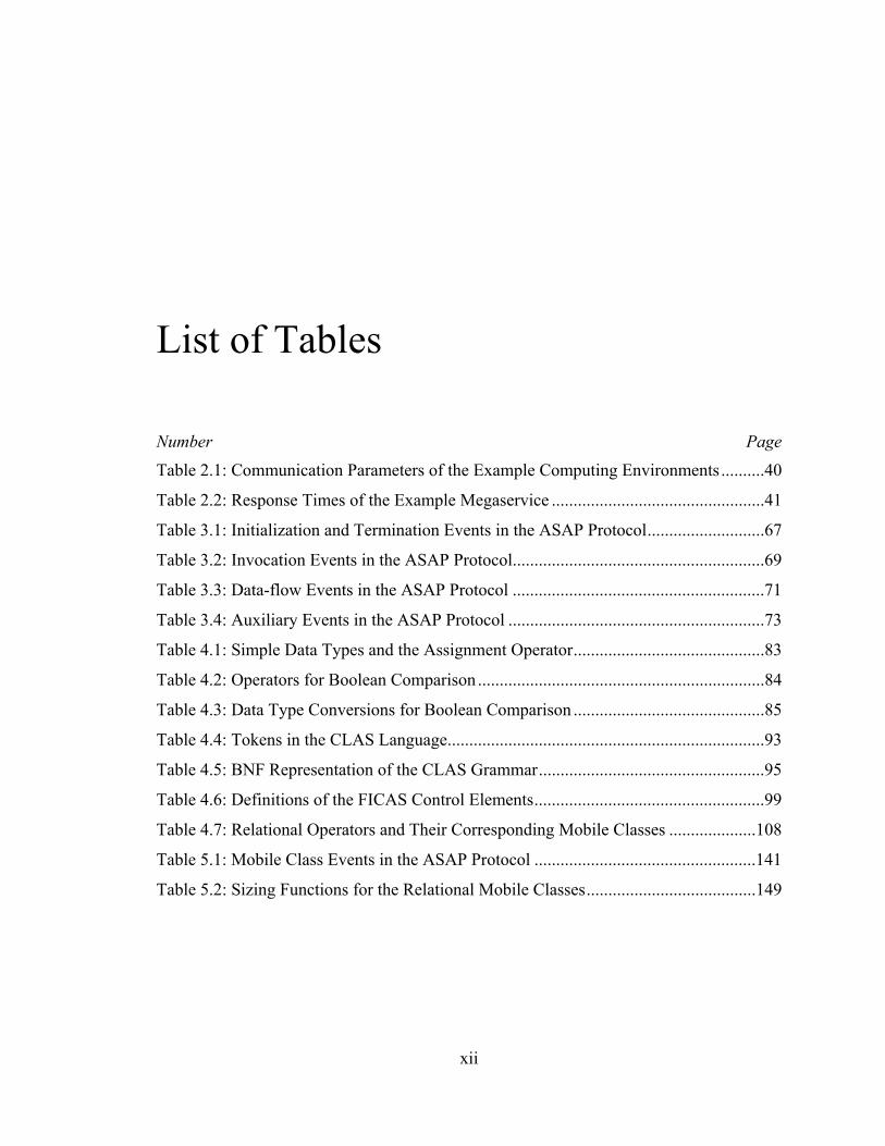
List of Tables
Number Page
Table 2.1: Communication Parameters of the Example Computing Environments..........40
Table 2.2: Response Times of the Example Megaservice .................................................41
Table 3.1: Initialization and Termination Events in the ASAP Protocol...........................67
Table 3.2: Invocation Events in the ASAP Protocol..........................................................69
Table 3.3: Data-flow Events in the ASAP Protocol ..........................................................71
Table 3.4: Auxiliary Events in the ASAP Protocol ...........................................................73
Table 4.1: Simple Data Types and the Assignment Operator............................................83
Table 4.2: Operators for Boolean Comparison ..................................................................84
Table 4.3: Data Type Conversions for Boolean Comparison ............................................85
Table 4.4: Tokens in the CLAS Language.........................................................................93
Table 4.5: BNF Representation of the CLAS Grammar....................................................95
Table 4.6: Definitions of the FICAS Control Elements.....................................................99
Table 4.7: Relational Operators and Their Corresponding Mobile Classes ....................108
Table 5.1: Mobile Class Events in the ASAP Protocol ...................................................141
Table 5.2: Sizing Functions for the Relational Mobile Classes.......................................149
xii
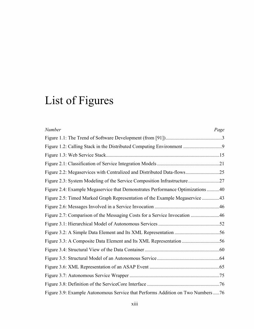
List of Figures
Number Page
Figure 1.1: The Trend of Software Development (from [91]).............................................3
Figure 1.2: Calling Stack in the Distributed Computing Environment ...............................9
Figure 1.3: Web Service Stack...........................................................................................15
Figure 2.1: Classification of Service Integration Models ..................................................21
Figure 2.2: Megaservices with Centralized and Distributed Data-flows...........................25
Figure 2.3: System Modeling of the Service Composition Infrastructure .........................27
Figure 2.4: Example Megaservice that Demonstrates Performance Optimizations ..........40
Figure 2.5: Timed Marked Graph Representation of the Example Megaservice ..............43
Figure 2.6: Messages Involved in a Service Invocation ....................................................46
Figure 2.7: Comparison of the Messaging Costs for a Service Invocation .......................46
Figure 3.1: Hierarchical Model of Autonomous Services .................................................52
Figure 3.2: A Simple Data Element and Its XML Representation ....................................56
Figure 3.3: A Composite Data Element and Its XML Representation ..............................56
Figure 3.4: Structural View of the Data Container ............................................................60
Figure 3.5: Structural Model of an Autonomous Service ..................................................64
Figure 3.6: XML Representation of an ASAP Event ........................................................65
Figure 3.7: Autonomous Service Wrapper ........................................................................75
Figure 3.8: Definition of the ServiceCore Interface ..........................................................76
Figure 3.9: Example Autonomous Service that Performs Addition on Two Numbers .....76
xiii
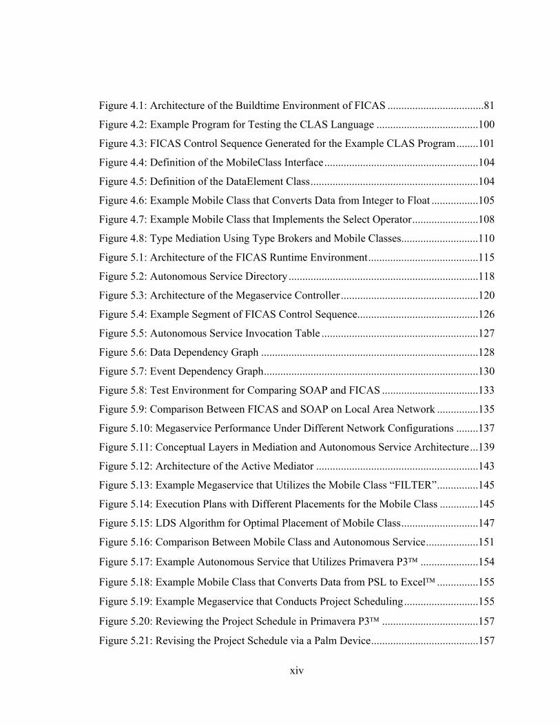
Figure 4.1: Architecture of the Buildtime Environment of FICAS ...................................81
Figure 4.2: Example Program for Testing the CLAS Language .....................................100
Figure 4.3: FICAS Control Sequence Generated for the Example CLAS Program........101
Figure 4.4: Definition of the MobileClass Interface........................................................104
Figure 4.5: Definition of the DataElement Class.............................................................104
Figure 4.6: Example Mobile Class that Converts Data from Integer to Float .................105
Figure 4.7: Example Mobile Class that Implements the Select Operator........................108
Figure 4.8: Type Mediation Using Type Brokers and Mobile Classes............................110
Figure 5.1: Architecture of the FICAS Runtime Environment........................................115
Figure 5.2: Autonomous Service Directory .....................................................................118
Figure 5.3: Architecture of the Megaservice Controller ..................................................120
Figure 5.4: Example Segment of FICAS Control Sequence............................................126
Figure 5.5: Autonomous Service Invocation Table .........................................................127
Figure 5.6: Data Dependency Graph ...............................................................................128
Figure 5.7: Event Dependency Graph..............................................................................130
Figure 5.8: Test Environment for Comparing SOAP and FICAS ...................................133
Figure 5.9: Comparison Between FICAS and SOAP on Local Area Network ...............135
Figure 5.10: Megaservice Performance Under Different Network Configurations ........137
Figure 5.11: Conceptual Layers in Mediation and Autonomous Service Architecture...139
Figure 5.12: Architecture of the Active Mediator ...........................................................143
Figure 5.13: Example Megaservice that Utilizes the Mobile Class “FILTER”...............145
Figure 5.14: Execution Plans with Different Placements for the Mobile Class ..............145
Figure 5.15: LDS Algorithm for Optimal Placement of Mobile Class............................147
Figure 5.16: Comparison Between Mobile Class and Autonomous Service...................151
Figure 5.17: Example Autonomous Service that Utilizes Primavera P3 .....................154
Figure 5.18: Example Mobile Class that Converts Data from PSL to Excel ...............155
Figure 5.19: Example Megaservice that Conducts Project Scheduling...........................155
Figure 5.20: Reviewing the Project Schedule in Primavera P3 ...................................157
Figure 5.21: Revising the Project Schedule via a Palm Device.......................................157
xiv

Figure 5.22: Reviewing the Updated Project Schedule in Microsoft Excel.................158
Figure 5.23: Reviewing the Updated Schedule in Microsoft Project...........................158
xv
Chapter 1
Introduction
1.1 Overview
A software engineering paradigm where large software services are decomposed into
cooperating components has been envisioned for over 30 years [58]. Under this
paradigm, software components are linked together through an integration framework to
form composed software applications called megaservices [96]. Software components
are provided as processes managed by independent service providers. The components
have clearly defined functions with accessible interfaces. We call these software
components autonomous services. With the rapid development of the Internet and
networking technologies, the computing environment is evolving toward an
interconnected web of autonomous services, both inside and outside of enterprise
boundaries. The integration of the autonomous services becomes an important issue in
software engineering.
CHAPTER 1. INTRODUCTION 2
1.1.1 Composition of Autonomous Services
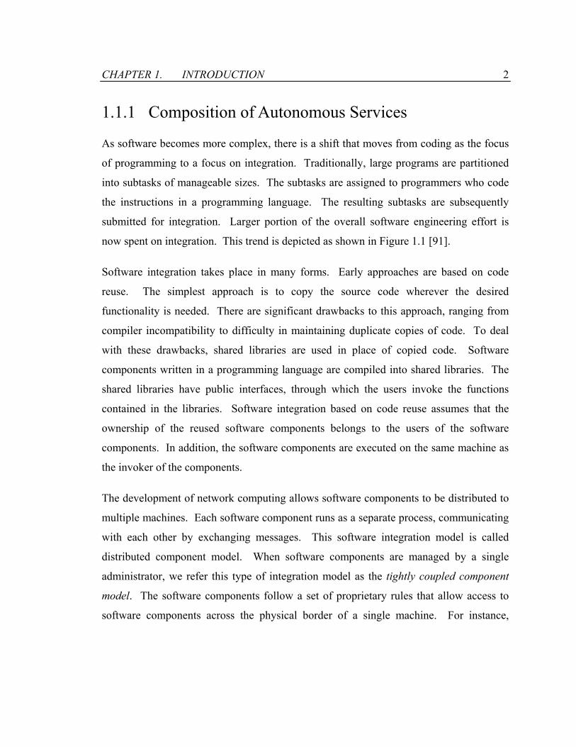
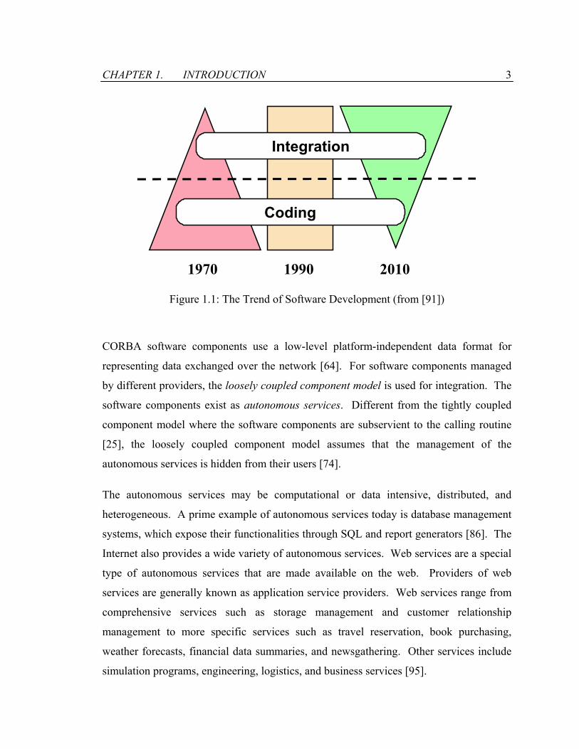
As software becomes more complex, there is a shift that moves from coding as the focus
of programming to a focus on integration. Traditionally, large programs are partitioned
into subtasks of manageable sizes. The subtasks are assigned to programmers who code
the instructions in a programming language. The resulting subtasks are subsequently
submitted for integration. Larger portion of the overall software engineering effort is
now spent on integration. This trend is depicted as shown in Figure 1.1 [91].
Software integration takes place in many forms. Early approaches are based on code
reuse. The simplest approach is to copy the source code wherever the desired
functionality is needed. There are significant drawbacks to this approach, ranging from
compiler incompatibility to difficulty in maintaining duplicate copies of code. To deal
with these drawbacks, shared libraries are used in place of copied code. Software
components written in a programming language are compiled into shared libraries. The
shared libraries have public interfaces, through which the users invoke the functions
contained in the libraries. Software integration based on code reuse assumes that the
ownership of the reused software components belongs to the users of the software
components. In addition, the software components are executed on the same machine as
the invoker of the components.
The development of network computing allows software components to be distributed to
multiple machines. Each software component runs as a separate process, communicating
with each other by exchanging messages. This software integration model is called
distributed component model. When software components are managed by a single
administrator, we refer this type of integration model as the tightly coupled component
model. The software components follow a set of proprietary rules that allow access to
software components across the physical border of a single machine. For instance,
CHAPTER 1. INTRODUCTION 3
Coding
Integration
1970 1990 2010
Figure 1.1: The Trend of Software Development (from [91])
CORBA software components use a low-level platform-independent data format for
representing data exchanged over the network [64]. For software components managed
by different providers, the loosely coupled component model is used for integration. The
software components exist as autonomous services. Different from the tightly coupled
component model where the software components are subservient to the calling routine
[25], the loosely coupled component model assumes that the management of the
autonomous services is hidden from their users [74].
The autonomous services may be computational or data intensive, distributed, and
heterogeneous. A prime example of autonomous services today is database management
systems, which expose their functionalities through SQL and report generators [86]. The
Internet also provides a wide variety of autonomous services. Web services are a special
type of autonomous services that are made available on the web. Providers of web
services are generally known as application service providers. Web services range from
comprehensive services such as storage management and customer relationship
management to more specific services such as travel reservation, book purchasing,
weather forecasts, financial data summaries, and newsgathering. Other services include
simulation programs, engineering, logistics, and business services [95].
CHAPTER 1. INTRODUCTION 4
There are three phases in composing autonomous services: (1) construction of the
services, (2) specification of megaservices, and (3) execution of megaservices. Different
design decisions need to be made for each phase, taking into consideration the complex
issues involved in each phase. The issues range from the scalability of the services, the
robustness of the services, the security of the service interaction, the effective and
convenient specification of the compositions, to the performance of the megaservices.
For the construction of autonomous services, a consistent access model is needed to
provide homogeneity to the services. Since autonomous services are developed and
maintained by independent providers, the access model hides away the disparities in the
network, platform, and language. The access model includes a data representation for
exchanging data among the services, and an interface through which the service
functionalities can be invoked. Services can use wrappers to convert data between their
internal data representations and a common representation. The use of wrappers for data
integration has been examined separately in collaboration with Cheng, et al [21, 54]. As
a result, the autonomous services are utilized as if they were locally available to the
megaservice.
To facilitate service integration, the autonomous services are assumed to handle requests
as transactions, and the services are designed to achieve the ACID semantics (i.e.,
atomicity, consistency, isolation, and durability) [41, 60]. The ACID semantics places
strict requirements on the concurrency and fault-handling behavior of the services. For
atomicity, an autonomous service processes a request as a single logical unit with respect
to other transactions and failures. For consistency, the service either creates a new valid
state of data after processing the request, or if any failure occurs, returns the data to
before the request. For isolation, the processing of one request by the service should not
affect the processing of another request by the service. For durability, the service saves
the committed data so that data is always available in its correct state. By conforming to
the ACID semantics, the service is well designed to handle concurrent invocations and
failures. The ACID semantics can be relaxed sometimes to simplify the construction of

CHAPTER 1. INTRODUCTION 5
the service. For instance, the consistency requirement can be relaxed. Rather than
returning the data to the state before the request when a failure occurs, the service may
only guarantee that the data is in a valid state after handling the failure. On the other
hand, a client of the service is required to handle the situations when the service fails to
process its requests [27, 28].
Security in the integration environment is another important issue. Interactions among
services need to be authenticated. Each service has to verify that its clients possess the
necessary access rights, and the client has to verify that the services are not counterfeited.
Encryption and certification technologies can be applied to ensure the authenticity of the
service interactions [48, 51]. The result is that mutual trust can be established among the
services and their clients.
Provided with an integration environment where service functionalities can be accessed, a
megaprogrammer can define for a megaservice which autonomous services are invoked,
what service functionalities are utilized, and how the functionalities are put together. The
megaprogrammer is not expected to be a technical expert of middleware systems or an
experienced programmer. Instead, the megaprogrammer would focus on solving the
problem at hand, e.g., obtaining information from a weather forecast service and feeding
that information to a project scheduling service. Tools are needed to provide the high-
level abstractions for compositions and hide the implementation details away from the
megaprogrammer [92].
Among the many issues in service composition, this thesis focuses on performance. The
objective is to explore the technologies that enable efficient execution of megaservices.
At the same time, other issues are taken into consideration. For instance, it is an
underlying assumption that the integration of large number of autonomous services
should be supported. Furthermore, performance gain should not come at the sacrifice of
ease of composition.
CHAPTER 1. INTRODUCTION 6
1.1.2 Distributed Data-flow Model
A megaservice is executed by exchanging messages with autonomous services. Control
messages are used to coordinate the execution of the services, and data messages are used
to exchange data among the services. The control messages involved in a task form a
control-flow, and the data messages involved in the task form a data-flow. The
management of the control-flows and data-flows affects the performance of the
megaservice. Traditionally, a megaservice is the central controller for invoking,
monitoring, querying, and terminating autonomous services. The megaservice acts as a
client that makes requests to the autonomous services, which function as servers. The
autonomous services process the data supplied by the megaservice and return the result to
the megaservice. Since the megaservice is the central hub of all data traffic, this
execution model behaves as a centralized data-flow model. Examples of the centralized
data-flow model can be found in software integration frameworks such as CORBA [64],
J2EE [13], and Microsoft .NET [47].
This thesis demonstrates through a theoretical analysis that the centralized data-flow
model is not efficient for composing autonomous services that communicate large
volumes of data. In the centralized data-flow model, the megaservice acts as a hub to
collect and to forward data to autonomous services even when the data produced by one
service is utilized by another service. Since the data is sent indirectly, redundant data
traffic occurs. Furthermore, the megaservice in the centralized data-flow model becomes
a communication bottleneck and a critical system resource. In this thesis, a distributed
data-flow model is proposed. In the distributed data-flow model, data are exchanged
directly among the autonomous services, and redundant data traffic is eliminated. The
distributed data-flow model utilizes the existing communication network among the
autonomous services and alleviates the communication load on the megaservice. Finally,
since data is distributed among the autonomous services, computations can be distributed
to allow the data to be processed across the network.
CHAPTER 1. INTRODUCTION 7
This thesis presents an implementation of the distributed data-flow model, namely the
Flow-based Infrastructure for Composing Autonomous Services (FICAS). FICAS is a
collection of software modules that support the three phases of service composition:
• Construction of autonomous services. The distributed data-flow model must support
direct data communications among the services. Within an autonomous service, the
data-flows are separated from the control processing. While the autonomous service
is coordinated by one entity, the input data may come from another entity, and the
output data may be sent to yet another entity. In FICAS, a metamodel is defined to
coordinate the autonomous services and to specify the distribution of data-flows.
• Specification of megaservices. Abstractions are necessary to describe the behaviors
of the megaservice. In FICAS, a high-level language is introduced and designed to
separate the compositional specification from the computational specification of a
megaservice. The compositional specification defines the relationships and the data
dependencies among the autonomous services. For computational specification,
mobile class is introduced and is used to specify how data generated by the
autonomous services should be processed by the megaservice.
• Execution of megaservices. A megaservice is managed by a central controller, which
serves as the sole coordinator of all the autonomous services that make up the
megaservice. Parallelism among the autonomous services is exploited during the
execution of the megaservice, with the assumption that the autonomous services
without data dependencies can be executed in parallel. While there is extensive
literature on parallel job scheduling [32, 33], FICAS focuses on the utilization of the
distributed data-flows to conduct performance optimization for megaservices.
As an experimental implementation of the distributed data-flow model, FICAS reaffirms
the findings of the theoretical analysis. In addition, FICAS provides a test bed for
investigating performance issues along with other complex issues involved in service
composition.
CHAPTER 1. INTRODUCTION 8
1.2 Related Research
There are several existing approaches in building frameworks where a number of
distributed software components may be integrated and work together. This section
provides a brief review on some of these existing approaches.
1.2.1 Distributed Computing Environment
The Distributed Computing Environment (DCE) from the Open Software Foundation
(OSF) is a collection of modern concepts and products that help users set up and run
client server applications in a heterogeneous computer network [65, 66, 77]. DCE is one
of the earlier efforts in enabling interoperability among distributed software components.
It provides developers with capabilities to hide differences among the hardware and
software elements in a large network. DCE provides many functions that can be found in
other computer networking environments, but packages the functions to make them easier
to use. For instance, the Remote Procedure Call (RPC) facility provides a way of
communicating between software modules running on different systems. The RPC is
much simpler to code than earlier methods, such as socket calls. The RPC automatically
converts data from the format used by one computer to that used by another.
DCE establishes a framework through which functionalities from multiple software
components can be integrated in a homogenous manner. A procedural program can be
distributed onto multiple computers via the following steps:
1. Partition the program's data and the functions into multiple components that have
clearly defined RPC interfaces;
2. Distribute those components across multiple hosts; and
3. Change function calls for the components to RPCs.
CHAPTER 1. INTRODUCTION 9
Client Host
Client OS
Client Stub GeneratedBy IDL Compiler
Application Code
Server Host
Server OS
Service Code
Server Stub GeneratedBy IDL Compiler
Client Application Distributed Component
Communication Network
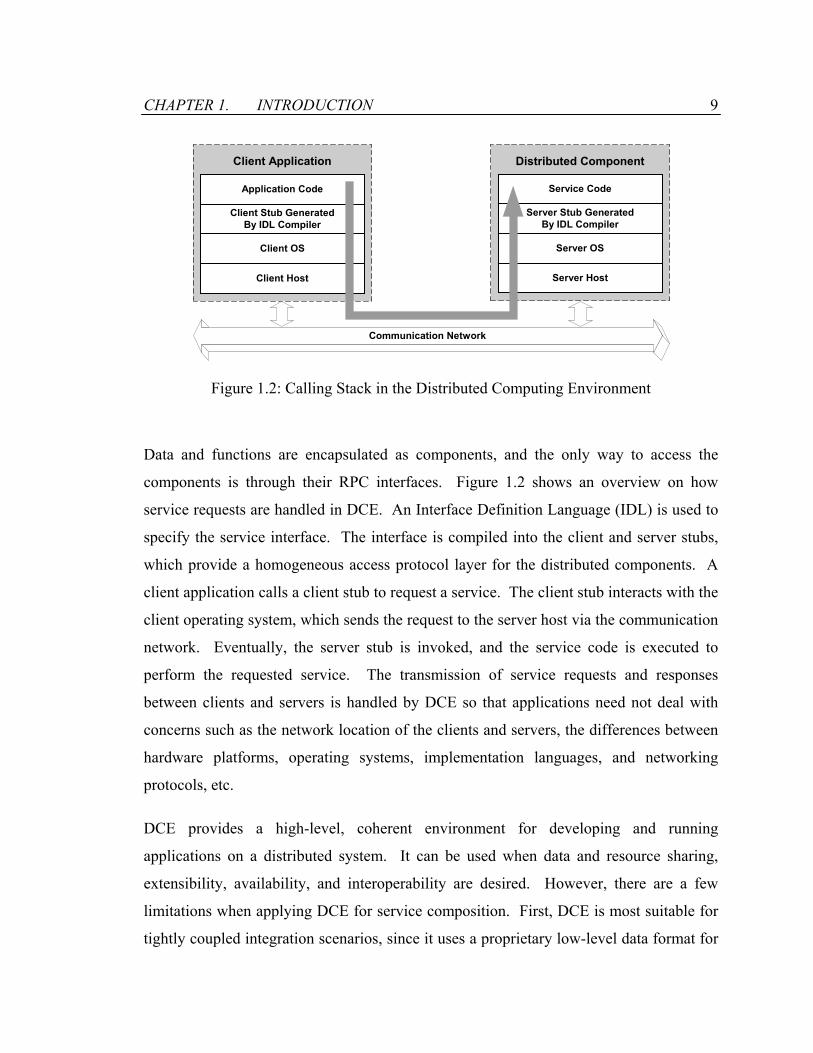
Figure 1.2: Calling Stack in the Distributed Computing Environment
Data and functions are encapsulated as components, and the only way to access the
components is through their RPC interfaces. Figure 1.2 shows an overview on how
service requests are handled in DCE. An Interface Definition Language (IDL) is used to
specify the service interface. The interface is compiled into the client and server stubs,
which provide a homogeneous access protocol layer for the distributed components. A
client application calls a client stub to request a service. The client stub interacts with the
client operating system, which sends the request to the server host via the communication
network. Eventually, the server stub is invoked, and the service code is executed to
perform the requested service. The transmission of service requests and responses
between clients and servers is handled by DCE so that applications need not deal with
concerns such as the network location of the clients and servers, the differences between
hardware platforms, operating systems, implementation languages, and networking
protocols, etc.
DCE provides a high-level, coherent environment for developing and running
applications on a distributed system. It can be used when data and resource sharing,
extensibility, availability, and interoperability are desired. However, there are a few
limitations when applying DCE for service composition. First, DCE is most suitable for
tightly coupled integration scenarios, since it uses a proprietary low-level data format for
CHAPTER 1. INTRODUCTION 10
representing the data for exchange among distributed components over the network.
Second, DCE does not support languages other than C. Extensive programming expertise
is required to compose service functionalities. Third, DCE is no longer in development;
it is not being maintained, nor is it being ported to the current releases of operating
systems. Finally, the communications in DCE among the clients and the components
utilize the centralized data-flow model, and there is no distinction between control-flows
and data-flows. As this thesis will show, the centralized data-flow model is not suitable
for the integration of components that require the exchange of large volumes of data.
1.2.2 Common Object Request Broker Architecture
The Common Object Request Broker Architecture (CORBA) makes the reuse of software
possible through distributed object computing, which combines the concept of distributed
computing with object-oriented computing [64, 67]. As two related distributed
computing technologies, CORBA and DCE share many similarities. In fact, CORBA can
be regarded as the object-oriented heir to DCE. Both use IDL to define the service
interface and compiles IDL into client and server stubs. Both use the same calling stack
(as previously shown in Figure 1.2) for invoking distributed software components. The
fundamental difference between CORBA and DCE lies in the fact that DCE was
designed to support procedural programming, whereas CORBA was designed to support
object-oriented programming. Object-oriented programming environments are usually
characterized by their support for encapsulation, abstraction, inheritance, and
polymorphism. On the other hand, a procedural programming environment can be used
to implement an object-oriented programming environment. Many CORBA systems are
implemented on top of DCE.
CORBA has the advantage of being object-oriented, more modern and supports more
comprehensive features than DCE. However, CORBA has had a great disadvantage of
being too low-level and complicated. Comparing to DCE, CORBA is difficult to learn,
and often requires skillful developers to use. For service composition, CORBA shares

CHAPTER 1. INTRODUCTION 11
many issues that exist in DCE: (1) CORBA is most suitable for composition when the
user of the software components also owns the components; (2) CORBA lacks the high-
level abstraction in its programming support for conducting service composition [80];
and (3) CORBA is inefficient when integrating services that communicate large volumes
of data, since it uses the centralized data-flow model.
1.2.3 CHAIMS
The Compiling High-level Access Interfaces for Multi-site Software (CHAIMS) project
focuses on the composition of large distributed services [59, 74, 80, 92]. Rather than
following the traditional waterfall model for developing software applications, which
starts from specifications, through design, to code generation, CHAIMS assumes that
large applications can best be composed from existing services through
megaprogramming [14]. In megaprogramming, functionalities of services provided by
large organizations are captured by megamodules. The megamodules are internally
homogeneous, independently maintained software systems managed by a community
with its own terminology, goals, knowledge and programming traditions. Each
megamodule describes its externally accessible data structures and operations and has an
internally consistent behavior.
A key feature of CHAIMS is the high-level compositional language CLAM [80]. As a
purely compositional language, CLAM does not include any primitives for computation.
The separation of the composition from the computation reduces the required
programming expertise and provides a clean way to specify megaservices. Furthermore,
CLAM is intended for large-scale environment where performance is important. The
long duration of megamodule execution necessitates asynchronous invocation and
collection of results. Whereas traditional programming languages assume synchrony in
the invocation of remote routines, CLAM extends the simple notion of composition by
splitting the traditional invocation to provide parallelism for asynchronicity. The
divisions are the initialization, execution, and result delivery phases of programs, due to
CHAPTER 1. INTRODUCTION 12
the fact that each of these program phases behaves differently. Also, CLAM supports
heterogeneous computing environment, and is not tied to any specific communication
protocols. The compiler for CLAM generates a variety of invocation sequences for
current and developing standards of software interoperation, e.g., CORBA and JAVA
RMI. Finally, by not conducting computations on user’s data, CLAM is not restricted in
its ability to pass data between arbitrary megamodules. CLAM uses an opaque data type
to handle all data objects returned by the megamodules.
CHAIMS serves as a point of departure for this thesis. FICAS follows the
megaprogramming paradigm. The autonomous services are the megamodules, and
service composition is regarded as an act of megaprogramming. The compositional
language in FICAS is based on CLAM, and FICAS utilizes many optimization
techniques employed by CHAIMS to improve the performance of the composed services.
On the other hand, FICAS extends CHAIMS in several areas. First and foremost, FICAS
investigates the use of distributed data-flows for the execution of the composed services.
Megamodules are built as autonomous services that separate their data-flows from their
control-flows. The autonomous services are centrally coordinated in the same fashion as
in CHAIMS, however the data can be directly exchanged among the services in FICAS.
Second, although it separates composition from computation, FICAS improves on
CHAIMS’s ability to support computation through the use of mobile class to conduct
dynamic information processing. Third, FICAS extends the megaprogramming model.
The megamodules are no longer software entities providing fixed functionalities.
Through active mediation, a service client can send dynamic routines to an autonomous
service to expand the functionalities of the service. This increases the customizability
and flexibility of the autonomous service.
1.2.4 Shared Dataspace
A shared dataspace is a place where arbitrary, application-specific objects can be shared
among distributed users [2, 76]. It is used as a medium for communication in a
CHAPTER 1. INTRODUCTION 13
distributed and parallel data-driven system. The shared medium also becomes a
synchronization mechanism during the concurrent execution of the processes involved in
a computation. Conceptually centralized, shared dataspace can be implemented as a
distributed infrastructure, similar to the concept of building a distributed shared memory
system to provide the abstraction of the shared memory across multiple network nodes.
Operating as a global communication buffer, a shared dataspace plays the role of traffic
cop for data flowing from one process to another in parallel and distributed systems. The
shared dataspace imposes no schema restrictions, ideal for distributed programming
where a general data delivery mechanism is needed. Linda and TSpaces are two shared
dataspace systems. Linda [16, 17, 37, 38] is one of the original systems that use the
shared dataspace model. The IBM TSpaces system [98] extends the shared dataspace
model with database features, e.g., persistent repository, indexing and query capabilities.
The shared dataspace can be used to conduct service integration when the application
scenario is data driven. For instance, TSpaces was used to build the Event Heap for the
Stanford Interactive Workspaces Project [34]. In the shared dataspace, the relationships
among distributed components are implicitly implied rather than explicitly specified.
Each component is responsible for detecting the presence of data values and examining
their actual contents. The shared dataspace approach lacks the mechanism to conduct
central coordination, and therefore is ineffective when it is desired to define a process
flow for the distributed components. FICAS, on the other hand, is more suitable for
integration scenarios that are process driven. The process flow is explicitly specified, and
the dependencies of the distributed components are predefined. Furthermore, the shared
dataspace approach and FICAS differ in how the service composition is specified. The
shared dataspace approach does not separate between computation, communication and
synchronization in the distributed components. Each component is a “smart” entity in
which the computational code is interspersed with the communication, coordination and
synchronization code. The shared dataspace approach places much burden on the
development of the distributed components. FICAS relies on the “dumb” services that
CHAPTER 1. INTRODUCTION 14
use a simple request reply model. The services perform computations when and only
when they are asked to. This approach reduces the complexity in developing the
services.
1.2.5 Web Services
The concept of web services has emerged as an important paradigm for general
application integration in the Internet environment. Web services are self-contained, self-
describing, modular applications that can be described, published, located and invoked
across the Web [78]. Web services perform functions that can be anything from simple
requests to complicated business processes. Related to this thesis, web services are
autonomous services in the context of the Web.
Interactions with the web services are conducted through SOAP (Simple Object Access
Protocol) [15]. SOAP is an XML-based messaging protocol for information exchange in
a decentralized, distributed environment. SOAP is essentially a flexible form of the
traditional remote procedure call (RPC) mechanism for gluing heterogeneous distributed
applications together. XML-based messaging allows the applications running on
different platforms to understand the exchange message without the need to conduct data
marshalling. Another key advantage of SOAP is its simplicity, which enables its quick
and wide adoption. SOAP is intended to provide the basic functionality as a messaging
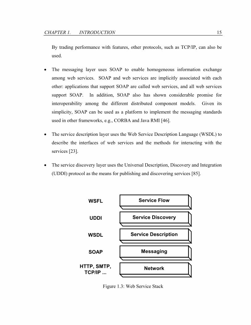
protocol for invoking web services. The complex functionalities that exist in other
distributed component middleware technologies are supported by separate level of
protocols in the web service stack, as shown in Figure 1.3:
• The bottom layer supports the transportation of messages among web services.
HTTP and SMTP are the two widely adopted protocols for exchanging messages in
the distributed computing environments. They come with many nice features such as
easy routing through firewalls, extensible security and authentication features, etc.
CHAPTER 1. INTRODUCTION 15
By trading performance with features, other protocols, such as TCP/IP, can also be
used.
• The messaging layer uses SOAP to enable homogeneous information exchange
among web services. SOAP and web services are implicitly associated with each
other: applications that support SOAP are called web services, and all web services
support SOAP. In addition, SOAP also has shown considerable promise for
interoperability among the different distributed component models. Given its
simplicity, SOAP can be used as a platform to implement the messaging standards
used in other frameworks, e.g., CORBA and Java RMI [46].
• The service description layer uses the Web Service Description Language (WSDL) to
describe the interfaces of web services and the methods for interacting with the
services [23].
• The service discovery layer uses the Universal Description, Discovery and Integration
(UDDI) protocol as the means for publishing and discovering services [85].
Network
Messaging
Service Description
Service Discovery
Service Flow
HTTP, SMTP,TCP/IP ...
SOAP
WSDL
UDDI
WSFL
Figure 1.3: Web Service Stack
CHAPTER 1. INTRODUCTION 16
• Sitting at the top layer of the web service stack, the Web Service Flow Language
(WSFL) manages business processes by modeling the participants in a workflow as
web services [53].
One main application area of web services is in workflow management. A workflow is
defined as “the automation of a business process, in whole or part, during which the
documents, information or tasks are passed from one participant to another for action,
according to a set of procedural rules” [97]. A workflow coordinates and monitors
execution of multiple tasks arranged to form a complex business process. The workflow
approach to coordinating task execution provides a natural way of exploiting distributed
object and middleware technologies [39]. The WSFL considers two models for
composing web services into integrated workflows. The first type is known as flow
model, where a composition is specified as an execution sequence of functionalities
provided by the web services. The second type is known as global model, where a
composition is specified as a description of how web services interact with each other in
the workflow. The interactions, modeled as links between endpoints of the web services’
interface, are decentralized and distributed. FICAS provides a hybrid of the two models
considered by WSFL. The specification of megaservices is based on the flow model.
Procedural rules are applied to control the execution of the autonomous services. At the
same time, the execution of megaservices utilizes the global model, where the
interactions among the services are decentralized and distributed.
The key difference between the web service stack and FICAS is in the messaging layer.
SOAP, based on the RPC call mechanism, invokes web services using function calls.
The interactions among the web services use the centralized data-flow model; the result
generated by a service is always returned to the entity that invokes the service. While
suitable for many application scenarios that integrate simple business services, SOAP is
not suitable for integrating large-scale services that communicate large volumes of data.
Through FICAS, the thesis demonstrates that the distributed data-flow model is better
suited by allowing direct data exchanges among the services.

CHAPTER 1. INTRODUCTION 17
1.3 Organization of the Thesis
The rest of this thesis is organized as follows:
• Chapter 2 categorizes service composition infrastructures into four models based on
how the control-flows and data-flows are managed. The advantages and
disadvantages of the models are analyzed using a formal performance model, where
parameters are assigned to the system resources such as computational nodes and
communication networks. We show that the distributed data-flow model has better
performance and it scales better than the centralized data-flow model. This analysis
provides the motivation to introduce FICAS, an infrastructure that utilizes the
distributed data-flow model for composing services.
• Chapter 3 defines a metamodel for the autonomous service to enable the
homogeneous access within FICAS. Given the metamodel, we define an access
protocol for the autonomous service, ASAP, through which the services can be
coordinated. The programming support for building ASAP-enabled autonomous
services is described in the chapter.
• Chapter 4 describes the buildtime environment of FICAS. The CLAS language is
introduced as the high-level compositional language to support the compositional
specification of megaservices. The language provides the support for the distribution
of data-flows among autonomous services. The mobile class is introduced to support
computational specification of megaservices. Using the mobile class, a megaservice
can separate its compositional specification from its computational specification.
• Chapter 5 describes the runtime environment of FICAS with the focus on the
planning and utilization of the distributed data-flows. Performance analysis is
conducted to compare the centralized and distributed data-flow models. Furthermore,
the chapter describes the runtime support for the mobile class that is used to conduct
CHAPTER 1. INTRODUCTION 18
active mediation and to minimize data-flows for the megaservice. Finally, an
infrastructure for engineering services is built based on FICAS to demonstrate that the
distributed data-flow model is suitable for composing large-scale software services.
• Chapter 6, the final chapter, contains a summary and discussion of the material
presented in this thesis. The chapter summarizes the research contributions. In
addition, the chapter discusses possible future extensions of the research.
Chapter 2
Service Composition Infrastructures
Software services managed autonomously are linked together to form a data processing
system controlled by a megaservice. Through composition, the megaservice utilizes the
functionalities provided by the autonomous services. The megaservice controls the
executions of the autonomous services by exchanging messages with the autonomous
services. The flow of the control messages is called control-flow. The executions of the
autonomous services generate data that need to be exchanged among the collaborating
autonomous services. The flow of data is called data-flow. The service composition
infrastructures differ in how the control-flows and the data-flows are managed. For
instance, control messages may be sent in sequence or in parallel; data messages may be
channeled through the megaservice or distributed among the autonomous services. The
performance of a megaservice can be greatly affected by the flows of the control and data
messages.
Parallel execution of autonomous services is the underlying assumption in service
composition, and the objective of control-flow scheduling is to take advantage of the
parallelism among autonomous services. Much research effort has been devoted to
control-flow scheduling in the past [1, 8, 82]. On the other hand, less attention has been
given to data-flow based performance optimization techniques. This chapter points out

CHAPTER 2. SERVICE COMPOSITION INFRASTRUCTURES 20
the significant impact of data-flow scheduling on megaservice performance and to
provide a mathematical basis for evaluating service composition infrastructures that
utilize distribution of data-flows.
2.1 Service Integration Models
Conceptually, a distributed computing environment is viewed as a set of processors
interconnected by a communication network. We regard the work performed by
autonomous services as a combination of computation and communication. Computation
is conducted on a processor and involves no interaction among the multiple processors.
For communication, messages are passed among the multiple processors. There are two
types of messages: control messages and data messages, distinguished by their use at the
recipient of the messages. Examples for control messages include service invocation
requests and status polling requests. Examples for data messages include engineering
design data and weather information to conduct simulation. Control messages are short
messages that are used to trigger and signal state changes at the autonomous services.
Data messages are used to transmit large data contents for the autonomous services.
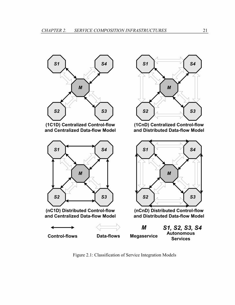
2.1.1 Model Classification
To execute a megaservice, control and data messages need to be exchanged among
autonomous services. The control-flow describes the set of partially ordered control
messages, and data-flow describes the set of partially ordered data messages. Figure 2.1
illustrates how the control-flows and data-flows are formed among the services. A thin
arrow indicates the existence of control-flows between two service nodes, and a thick
arrow indicates the existence of data-flows between two service nodes. Service
composition infrastructures are classified into four integration models:
CHAPTER 2. SERVICE COMPOSITION INFRASTRUCTURES 21
M
S1
S2 S3
S4
M
S1
S2 S3
S4
M
S1
S2 S3
S4
M
S1
S2 S3
S4
(1C1D) Centralized Control-flowand Centralized Data-flow Model
Control-flows Data-flows MegaserviceM
AutonomousServices
S1, S2, S3, S4
(1CnD) Centralized Control-flowand Distributed Data-flow Model
(nC1D) Distributed Control-flowand Centralized Data-flow Model
(nCnD) Distributed Control-flowand Distributed Data-flow Model
Figure 2.1: Classification of Service Integration Models

CHAPTER 2. SERVICE COMPOSITION INFRASTRUCTURES 22
• Centralized control-flow and centralized data-flow model (1C1D): Because of its
simplicity, the 1C1D model is the most widely used.
• Centralized control-flow and distributed data-flow model (1CnD): The 1CnD model
extends the 1C1D model by allowing data-flows to move directly among services,
bypassing the central control node.
• Distributed control-flow and centralized data-flow model (nC1D): The nC1D model
distributes the control-flows while maintaining a centralized hub for data-flow
exchanges. It is a variation of the 1C1D model with distributed control-flows.
• Distributed control-flow and distributed data-flow model (nCnD): The nCnD model
allows both control-flows and data-flows to be distributed. It is a variation of the
1CnD model with distributed control-flows.
The 1C1D model is described in Section 2.1.2. We combine the description of the
distributed control-flow models (i.e., nC1D and nCnD) in Section 2.1.3. Finally, the
1CnD model is introduced in 2.1.4.
2.1.2 Centralized Control-flow and Centralized Data-flow
Model
The Centralized Control-flow and Centralized Data-flow (1C1D) model has the simplest
structure. The megaservice is the central exchange point for both control and data
messages. The 1C1D model naturally fits the client-server architecture, where
autonomous services act as servers and the megaservice functions as the client. Data and
controls are passed from the megaservice to a desired autonomous service, and the results
are returned to the megaservice for further processing. When additional functionalities
are needed from other autonomous services, data and controls are again sent out from the
megaservice.
CHAPTER 2. SERVICE COMPOSITION INFRASTRUCTURES 23
In today’s practice, the 1C1D model dominates. Simplicity is its key advantage. Most
service integration environments, e.g., CORBA [64], J2EE [13], and Microsoft .NET
[47], use the 1C1D model. However, there are drawbacks associated with the centralized
approach. Since data generated by the autonomous services need to be processed by the
megaservice before being forwarded onto subsequent autonomous services, the processor
that the megaservice runs on must possess fair amount of processing power and
communication bandwidth. Many scenarios can be found to have difficulty in deploying
the 1C1D model. For example, Internet service composition occurs in an environment
where the autonomous services normally run on fairly high performance servers and the
megaservices run on devices that are configured for browsing rather than for processing.
Since large volumes of data may be produced, the megaservices become communication
bottlenecks in the 1C1D model. The centralized communication topology makes the
1C1D model not easily scalable. It is especially problematic in an Internet environment,
where the communication links between the megaservice and autonomous services are
likely to be of limited bandwidth. At the same time, since all the control-flows and data-
flows are channeled through the megaservice, there is no communication between any
pairs of autonomous services. The high-speed networks deployed between autonomous
services will not be utilized under the 1C1D model.
2.1.3 Distributed Control-flow Models
In the distributed control-flow models, control messages can be sent between autonomous
services, and the course of megaservice execution is coordinated by multiple autonomous
services. A good example of distributed control-flows can be found in data-flow
computer architectures [30, 36, 87] where the execution of a program is partially
controlled by the flow of data rather than successive fetching of instructions. A parallel
program is compiled into operational code segments that are distributed to distinctive
functional units, and the presence of operands activates the execution of the code
segments. Given its ability to exploit the natural parallelism of algorithms [31], data-
CHAPTER 2. SERVICE COMPOSITION INFRASTRUCTURES 24
flow computer architecture has been seen as a promising approach in designing high
performance multi-processor machines.
However, there are difficulties in effectively applying distributed control-flows to
conduct service composition. Since control-flows are coordinated in a distributed
fashion, operational code segments need to be distributed to relevant function units for
execution. This places the requirement for homogeneity on the underlying hardware
platform. Although such a requirement may easily be met in building parallel computers,
it is difficult to distribute arbitrary operational code segments in a heterogeneous service
composition infrastructure. In addition, there remain many technical challenges to
convert a centralized megaservice specification of control sequences into distributed
operational code segments that can be used to execute the megaservice. Due to these
limitations, distributed control-flows have been adopted only for special-purpose
applications, where code segments are installed on individual functional units and a
distributed application environment is constructed from bottom up. Hence, this thesis
will focus only on the centralized control-flow models, i.e., the 1C1D and 1CnD models.
2.1.4 Centralized Control-flow and Distributed Data-flow
Model
While maintaining the same centralized control-flow approach as in the 1C1D model, the
Centralized Control-flow and Distributed Data-flow (1CnD) model can improve
megaservice performance by exploiting the distribution of data-flows. The
improvements come from the scheme that data are passed directly between autonomous
services without going through the megaservice. Data communications among
autonomous services are coordinated, resulting in distributed data-flows. The
megaservice can instruct two autonomous services to establish a data-flow through which
data are directly exchanged, and the megaservice does not need to function as an
intermediate node on the data-flow path. For example, Figure 2.2(a) illustrates the
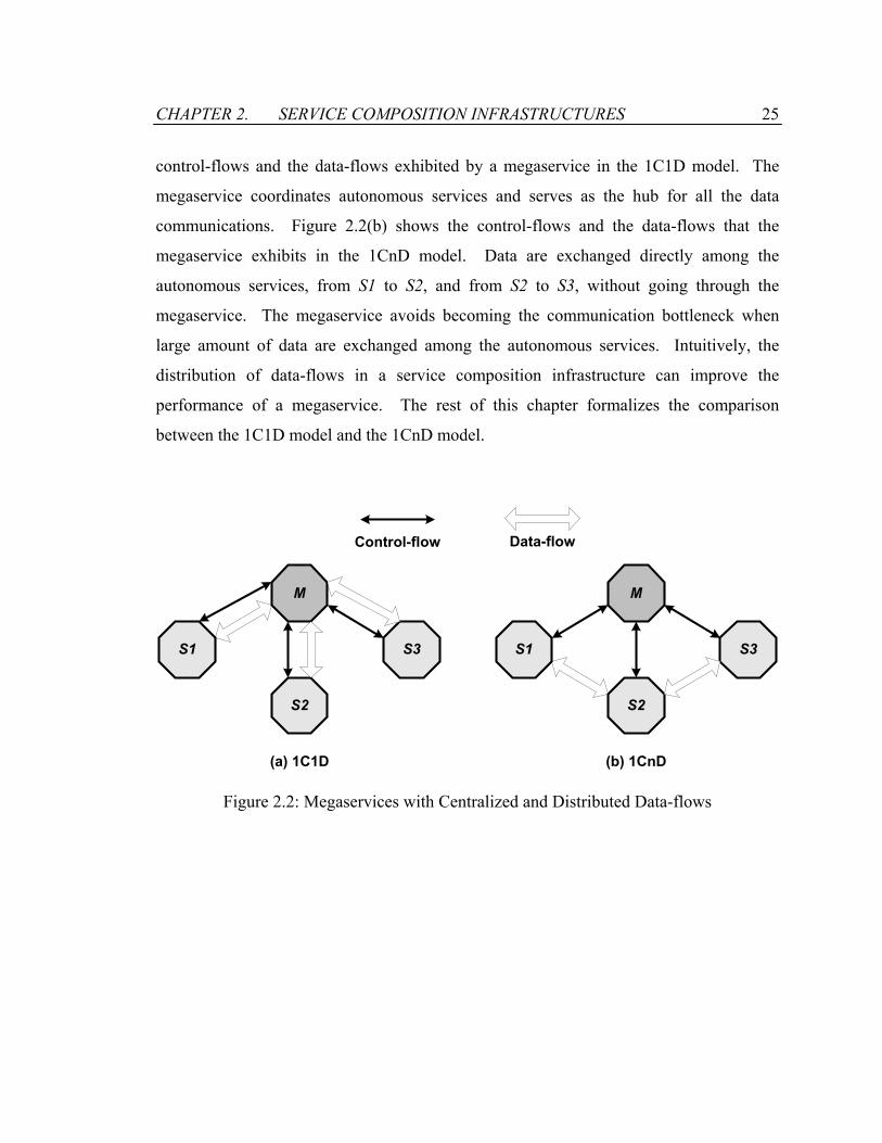
CHAPTER 2. SERVICE COMPOSITION INFRASTRUCTURES 25
control-flows and the data-flows exhibited by a megaservice in the 1C1D model. The
megaservice coordinates autonomous services and serves as the hub for all the data
communications. Figure 2.2(b) shows the control-flows and the data-flows that the
megaservice exhibits in the 1CnD model. Data are exchanged directly among the
autonomous services, from S1 to S2, and from S2 to S3, without going through the
megaservice. The megaservice avoids becoming the communication bottleneck when
large amount of data are exchanged among the autonomous services. Intuitively, the
distribution of data-flows in a service composition infrastructure can improve the
performance of a megaservice. The rest of this chapter formalizes the comparison
between the 1C1D model and the 1CnD model.
M
S1
S2
S3
M
S1
S2
S3
(a) 1C1D
Control-flow Data-flow
(b) 1CnD
Figure 2.2: Megaservices with Centralized and Distributed Data-flows

CHAPTER 2. SERVICE COMPOSITION INFRASTRUCTURES 26
2.2 System Modeling
In order to evaluate the performance of megaservices under different integration models,
we need to first characterize and give a formal definition to the components within the
computing environment. The components include the hardware platform, the
autonomous services, and the megaservices.
As illustrated in Figure 2.3, the hardware platform is modeled as a set of processor nodes
P0, P1, … , Pn tied together by a completely connected network. Associated with every
processor Pi is the processor capacity CPi expressed in terms of the number of cycles that
the processor can handle in unit time. Furthermore, associated with each pair of
processors (Pi, Pj) is the communication capacity CMij expressed in terms of the volume
of data that can be transmitted from processor Pi to processor Pj in unit time. A
communication channel originating from a processor Pi to itself may also exist, with
capacity CMii. The communication network is modeled as a set of point-to-point links
that interconnect every processor with each other. As there is no shared medium among
links, each communication link operates independent of each other. This model is a
simplified model for most of the real-world network architectures, but is sufficient to
serve the purpose of the analysis here. More complex models can be built by introducing
additional constraints on the system parameters.
Let S1, … , Sn denote a set of autonomous services, each performing some specific
operations. Conceptually, an autonomous service Si runs on a local processor Pi, and the
execution of Si is independent of any other autonomous services. In the case where
multiple services reside on the same processor, a physical processor can serve multiple
virtual processors and set appropriate capacity parameters for the virtual processors.
Complex autonomous services that involve multiple processors for execution can be
further partitioned into atomic service units such that each atomic service unit only
performs operations on its local processor. As a result, in our analysis we can establish a
simple one-to-one mapping between a processor and an autonomous service.

CHAPTER 2. SERVICE COMPOSITION INFRASTRUCTURES 27
......
CP2 CPn
CPn
CP1
CP0CM0n/CMn0
S1: f1 (SI1, SP1, SO1)
CM01/C
M10
S2: f2 (SI2, SP2, SO2) Sn: fn (SIn, SPn, SOn)
Sn: fn (SIn, SPn, SOn)M: (_, MP, _)
Figure 2.3: System Modeling of the Service Composition Infrastructure
A megaservice M is regarded as a partially ordered sequence of tasks for our performance
analysis. Tasks are classified as either local processing or remote invocations of the
autonomous services. The workload of each type of task is then evaluated. Without loss
of generality, we assume that the megaservice M runs on the processor P0. Thus, local
processing takes place on P0 and its workload is denoted as MP number of cycles. In the
case where the megaservice M runs on processor Pi (i≠0), we can treat the invocation of
the autonomous service Si as part of local processing. Remote invocations of
autonomous services is modeled using a frequency vector f1, … , fn, where fi denotes
the number of times Si is invoked during the execution of M. The autonomous service Si
is invoked by receiving input data of size SIi. It is executed at a cost of SPi expressed in
terms of the number of cycles. An output data of size SOi is generated as the result of
executing Si. Data-flows are modeled as a collection of communication messages. Each
message has an initialization cost, which is treated as a fixed size header added onto the
message. The size of the message header is denoted as a constant λ.
Given the mathematical model for the computing environment, we can analyze the
performance of a megaservice in the distributed data-flow model and compare with that
in the centralized data-flow model. We first assume that control messages are

CHAPTER 2. SERVICE COMPOSITION INFRASTRUCTURES 28
insignificant as compared to data messages in terms of both the consumed system
resources and the communication times. This is a valid assumption for most service
composition scenarios, where the volume of data-flows is much more than that of
control-flows. We therefore ignore control-flows and assume that the operations of
autonomous services are solely depending on the availability of their input data. Section
2.3 analyzes the impact of distributed data-flows on the system resources consumed by
megaservices. Section 2.4 analyzes the time to execute individual megaservices with or
without distributed data-flows. To complete the performance comparison, Section 2.5
brings control-flows into consideration. Assuming that the control message size is
comparable to the data message size, we compare the performance of a service invocation
for the 1C1D and the 1CnD models.
2.3 Aggregated Cost of a Megaservice
We first focus the analysis on the overall system bandwidth requirements of different
integration models. The aggregated cost of a megaservice measures the amount of
system resource consumed by the megaservice.
2.3.1 Aggregated Cost Definition
Before giving a definition of the aggregated cost of a megaservice, we need to first
determine the cost function for individual components of the system resource. In our
model, we define a cost evaluation function Cef, which is formally a mapping defined as
follows: Given a megaservice M and a set of processors P0, P1, … , Pn, the cost
evaluation function Cef(M) returns the tuple (vp, vm) , where
• vp = vpi | 0 ≤ i ≤ n, where vpi is the load in terms of the number of processor cycles
consumed by processor Pi.
CHAPTER 2. SERVICE COMPOSITION INFRASTRUCTURES 29
• vm = vmij | 0 ≤ i, j ≤ n, where vmij is the load due to the message traffic generated
from processor Pi and to processor Pj.
The vectors vp and vm represent, respectively, the processing costs and the
communication costs of the megaservice.
The aggregated cost of a megaservice is defined as the sum of all individual cost
components. We assume that the processing costs and the messaging costs of a
megaservice can be linearly scaled relative to each other. The weights of the scale given
to the processing costs and the messaging costs are denoted as α and β respectively.
Hence, we define the aggregated cost of a megaservice as:
∑∑≤≤=
×+×=nji
ij
n
ii vmvpMCOST
,00)( βα
where (vp, vm) = Cef(M) and α, β ≥ 0. The weights, α and β, can be set to appropriate
values to reflect the relative scarcity of processor resources to communication resources.
In the extreme case where α = 0, the system has unlimited processing power, and the
aggregated cost is a sum of the communication costs. On the other hand, if β = 0, the
system has unlimited networking bandwidth, and the aggregated cost is a sum of the
processing costs. The analysis of aggregated cost is now a problem of determining the
processing cost vp and the communication cost vm.
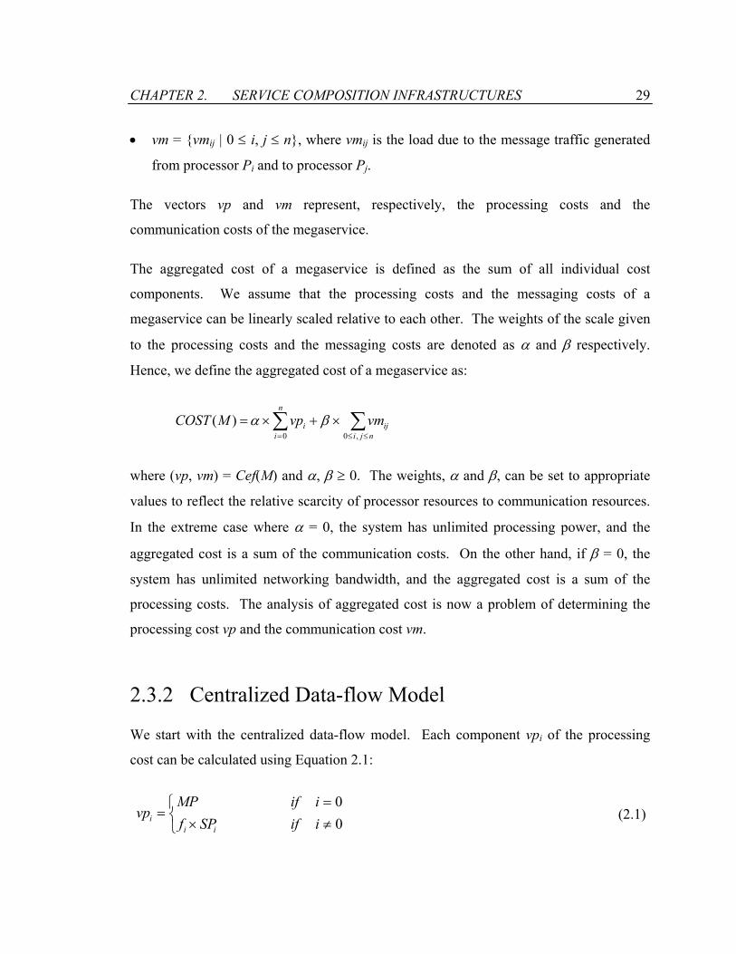
2.3.2 Centralized Data-flow Model
We start with the centralized data-flow model. Each component vpi of the processing
cost can be calculated using Equation 2.1:
≠×=
=00
iifSPfiifMP
vpii
i (2.1)

CHAPTER 2. SERVICE COMPOSITION INFRASTRUCTURES 30
The processing load on the processor P0 is MP, as defined earlier in the system model.
The megaservice M is the only local process running on P0. The processing load on
processor Pi is equal to the execution cost of the autonomous service Si that runs on the
processor multiplied by the number of times fi that the service Si is invoked.
The calculation of the messaging cost vm is equally straightforward. The only types of
network traffic in the system are caused by the invocation of services. Messages are sent
from P0 to other processors for the invocation of the autonomous services, and the results
are returned to P0 as messages originated from where the autonomous services are
executed. Each component vmij of the messaging cost can be calculated using Equation
2.2:
=≠+×≠=+×
=otherwise
jiifSOfjiifSIf
vm ii
jj
ij
00,0)(0,0)(
λλ
(2.2)
The input data SIj of the autonomous service Sj along with the message header λ is sent on
the communication link (P0, Pj) for each invocation of the service Sj. The load is
multiplied by fj, the number of times that Sj is invoked. The output data SOi of the
autonomous service Si along with the message header λ is sent on the communication link
(Pi, P0) for each invocation of the service Si. The load is multiplied by fi, the number of
times that Si is invoked. Since there is no other network traffic caused by the
megaservice, the messaging load on all other communication links is 0.
The aggregated cost COSTc(M) for the centralized data-flow model can thus be calculated
as:
∑∑
∑∑
==
≤≤=
++××+×+×=
×+×=
n
iiii
n
iii
njiij
n
iic
SOSIfSPfMP
vmvpMCOST
11
,00
)2()(
)(
λβα
βα (2.3)
CHAPTER 2. SERVICE COMPOSITION INFRASTRUCTURES 31
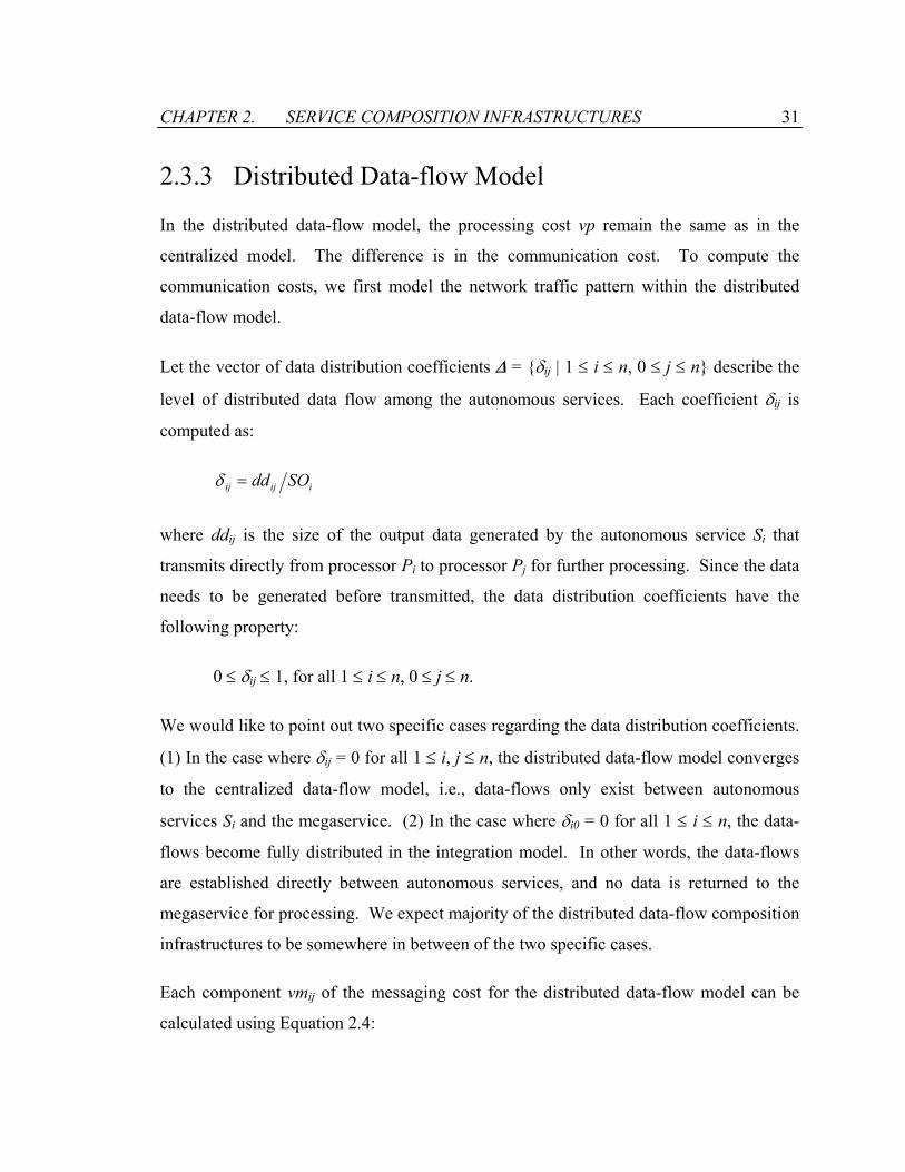
2.3.3 Distributed Data-flow Model
In the distributed data-flow model, the processing cost vp remain the same as in the
centralized model. The difference is in the communication cost. To compute the
communication costs, we first model the network traffic pattern within the distributed
data-flow model.
Let the vector of data distribution coefficients ∆ = δij | 1 ≤ i ≤ n, 0 ≤ j ≤ n describe the
level of distributed data flow among the autonomous services. Each coefficient δij is
computed as:
iijij SOdd=δ
where ddij is the size of the output data generated by the autonomous service Si that
transmits directly from processor Pi to processor Pj for further processing. Since the data
needs to be generated before transmitted, the data distribution coefficients have the
following property:
0 ≤ δij ≤ 1, for all 1 ≤ i ≤ n, 0 ≤ j ≤ n.
We would like to point out two specific cases regarding the data distribution coefficients.
(1) In the case where δij = 0 for all 1 ≤ i, j ≤ n, the distributed data-flow model converges
to the centralized data-flow model, i.e., data-flows only exist between autonomous
services Si and the megaservice. (2) In the case where δi0 = 0 for all 1 ≤ i ≤ n, the data-
flows become fully distributed in the integration model. In other words, the data-flows
are established directly between autonomous services, and no data is returned to the
megaservice for processing. We expect majority of the distributed data-flow composition
infrastructures to be somewhere in between of the two specific cases.
Each component vmij of the messaging cost for the distributed data-flow model can be
calculated using Equation 2.4:
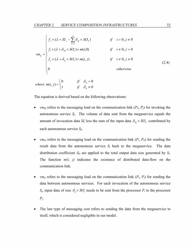
CHAPTER 2. SERVICE COMPOSITION INFRASTRUCTURES 32
≠≠××+×
=≠××+×
≠=×−+×
=
∑=
otherwise
jiifjimSOf
jiifimSOf
jiifSOSIf
vmiijj
iii
n
kkkjjj
ij
0
0,0),()(
0,0)0,()(
0,0)(
0
1
δλ
δλ
δλ
where
≠=
=0100
),(ij
ij
ifif
jimδδ
(2.4)
The equation is derived based on the following observations:
• vm0j refers to the messaging load on the communication link (P0, Pj) for invoking the
autonomous service Sj. The volume of data sent from the megaservice equals the
amount of invocation data SIj less the sum of the input data kkj SO×δ contributed by
each autonomous service Sk.
• vmi0 refers to the messaging load on the communication link (Pi, P0) for sending the
result data from the autonomous service Si back to the megaservice. The data
distribution coefficient δi0 are applied to the total output data size generated by Si.
The function m(i, j) indicates the existence of distributed data-flow on the
communication link.
• vmij refers to the messaging load on the communication link (Pi, Pj) for sending the
data between autonomous services. For each invocation of the autonomous service
Sj, input data of size iij SO×δ needs to be sent from the processor Pi to the processor
Pj.
• The last type of messaging cost refers to sending the data from the megaservice to
itself, which is considered negligible in our model.

CHAPTER 2. SERVICE COMPOSITION INFRASTRUCTURES 33
As a result, the aggregated cost of the megaservice for the distributed data-flow model
can be calculated using Equation 2.5:
∑ ∑
∑
∑∑
= =
=
≤≤=
××+×+++××
+×+×=
×+×=
n
i
n
jjiiii
n
iii
njiij
n
iid
jimfSOSIimf
SPfMP
vmvpMCOST
1 10
1
,00
),()))0,(1((
)(
)(
λδλβ
α
βα
(2.5)
2.3.4 Comparison of Centralized and Distributed Data-
Flow Models
From Equations 2.3 and 2.5, the difference in the aggregated costs between the
centralized and the distributed data-flow models can be calculated using Equation 2.6:
( )∑=
+×=−n
imessagedatadc iDiDMCOSTMCOST
1
)()()()( β
where
×−−××=
−××=
∑=
n
jjimessage
iiidata
jimfimfiD
SOfiD
1
0
),())0,(1()(
)1()(
λ
δ(2.6)
The performance difference is due to their data volumes and message overheads. The
first component, Ddata, represents the difference in the volumes of data-flow between the
two models. In the centralized data-flow model, all output data are sent back to the
megaservice. Whereas in distributed data-flow model, only a portion (i.e., δi0) of the data
are sent back to the megaservice. The second component, Dmessage, represents the
difference in messaging overheads between the two models. The distributed model
initiates more data messages than the centralized model. Since messages have an
CHAPTER 2. SERVICE COMPOSITION INFRASTRUCTURES 34
initialization cost, more messages may incur higher overall communication cost, even
though the amount of data content delivered by the messages decreases.
Typical applications of service composition are coarse-grain and distributed computing
scenarios, where the overhead is assumed to be smaller than the size of the messages
themselves, i.e., λ << SI, SO. Hence, the dominating factor in comparing aggregated cost
between the two models is Ddata. The distributed data-flow model is more appropriate for
service composition because of the better performance. On the other hand, in a fine-
grain, parallel computing scenario, the overhead cost of messages may become
significant and outweighs the savings from reduced data-flows.
2.4 Response Time For Megaservices
Another aspect of our performance analysis focuses on the response time, i.e., the elapsed
time between the start and the termination of a megaservice. The response time analysis
is useful in pinpointing bottlenecks of a system and gives guidance in designing a
scalable system.
We look at the response times for two types of atomic operations performed by a
megaservice: executing a code segment on a processor and sending a message between
two processors. It is assumed that the response time for atomic operations is the
workload per resource capacity. Hence local processing of computational load vpi on
processor Pi wih capacity CPi has a response time of vpi/CPi, and sending a message of
size vmij from processor Pi to processor Pj with communication capacity CMij has a
response time of vmij/CMij.
A megaservice can be considered as a sequence of partially ordered distributed atomic
operations. The scheduling of the atomic operations affects the response time of a
megaservice. By executing atomic operations in parallel, the processors in the network
CHAPTER 2. SERVICE COMPOSITION INFRASTRUCTURES 35
are better utilized, and can potentially decrease the overall response time of a
megaservice. In the following, we analyze the parallel executions of megaservice by
considering two invocation schemes:
• The serialized invocation scheme adopts a single threaded execution model.
Autonomous services are invoked in the order as specified by the megaservice.
Given the deterministic nature of the serialized invocation scheme, we can compute
and compare quantitatively the response times of megaservices.
• The parallel invocation scheme favors overlapping execution of autonomous services,
subject to data dependencies. We will model megaservices using Petri nets and
conduct qualitative comparison of the centralized data-flow model against the
distributed data-flow model.
Interference of activities within the processor network, such as concurrent instances of
other megaservices, can generate conflicts in allocation of system resources, causing
variance in the response time. While formal analysis of interacting system models is
sometimes possible, discrete-event simulation remains the most general technique
available for assessing the model’s behavior. For the analysis of response time, we
assume a single-user model, where system usage is light and there is no conflicts on
system resource allocation.
2.4.1 Serialized Invocation of Megaservices
The response time of a megaservice under serialized invocation scheme can be calculated
using Equation 2.7. The response time T(M) for the megaservice M consists of two
components: (1) TM is the time to perform the computational load MP on the processor
P0 with capacity CP0. TM is the same for both the centralized and the distributed data-
flow models. (2) TS is the total elapsed time for executing the autonomous services.
Each autonomous service Si consists of three sequential tasks: the input task with elapsed
time TSIi during which input parameters are prepared, the processing task with elapsed
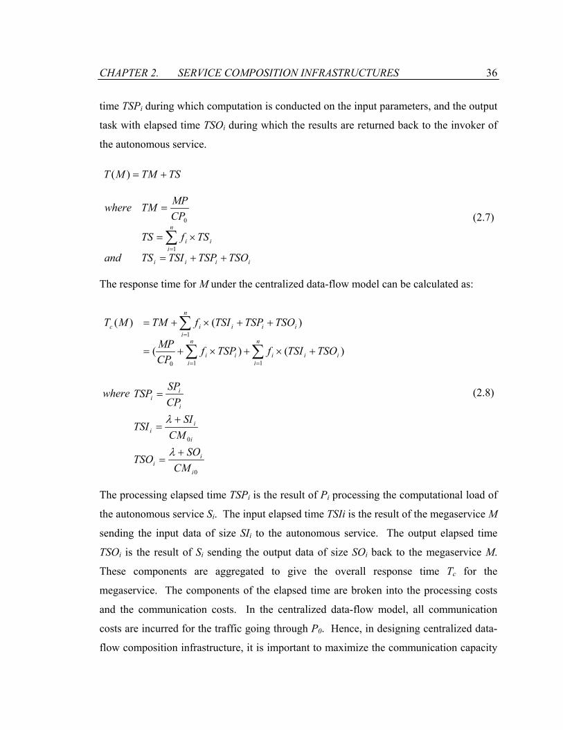
CHAPTER 2. SERVICE COMPOSITION INFRASTRUCTURES 36
time TSPi during which computation is conducted on the input parameters, and the output
task with elapsed time TSOi during which the results are returned back to the invoker of
the autonomous service.
TSTMMT +=)(
iiii
n
iii
TSOTSPTSITSand
TSfTS
CPMPTMwhere
++=
×=
=
∑=1
0
(2.7)
The response time for M under the centralized data-flow model can be calculated as:
∑∑
∑
==
=
+×+×+=
++×+=
n
iiii
n
iii
n
iiiiic
TSOTSIfTSPfCPMP
TSOTSPTSIfTMMT
110
1
)()(
)()(
where
0
0
i
ii
i
ii
i
ii
CMSO
TSO
CMSI
TSI
CPSP
+=
+=
=
λ
λ
TSP
(2.8)
The processing elapsed time TSPi is the result of Pi processing the computational load of
the autonomous service Si. The input elapsed time TSIi is the result of the megaservice M
sending the input data of size SIi to the autonomous service. The output elapsed time
TSOi is the result of Si sending the output data of size SOi back to the megaservice M.
These components are aggregated to give the overall response time Tc for the
megaservice. The components of the elapsed time are broken into the processing costs
and the communication costs. In the centralized data-flow model, all communication
costs are incurred for the traffic going through P0. Hence, in designing centralized data-
flow composition infrastructure, it is important to maximize the communication capacity
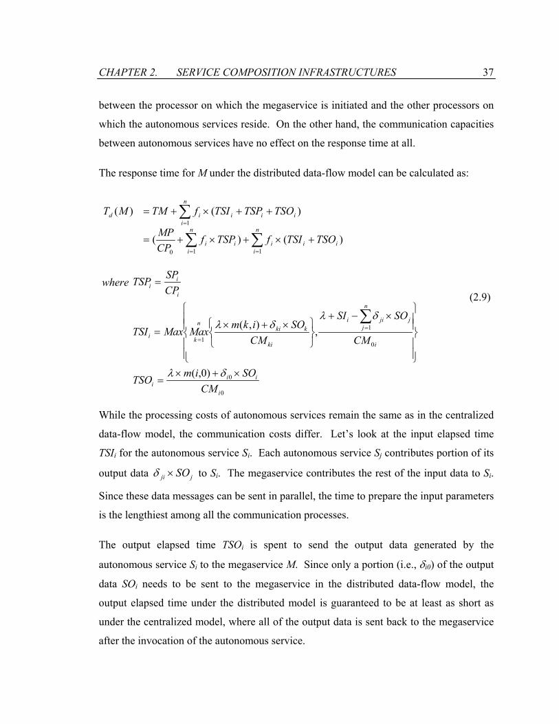
CHAPTER 2. SERVICE COMPOSITION INFRASTRUCTURES 37
between the processor on which the megaservice is initiated and the other processors on
which the autonomous services reside. On the other hand, the communication capacities
between autonomous services have no effect on the response time at all.
The response time for M under the distributed data-flow model can be calculated as:
∑∑
∑
==
=
+×+×+=
++×+=
n
iiii
n
iii
n
iiiiid
TSOTSIfTSPfCPMP
TSOTSPTSIfTMMT
110
1
)()(
)()(
where
0
0
0
1
1
)0,(
,),(
i
iii
i
n
jjjii
ki
kkin
ki
i
ii
CMSOimTSO
CM
SOSI
CMSOikmMaxMax
CPSPTSP
×+×=
×−+
×+×
=
=
∑=
=
δλ
δλδλTSI
(2.9)
While the processing costs of autonomous services remain the same as in the centralized
data-flow model, the communication costs differ. Let’s look at the input elapsed time
TSIi for the autonomous service Si. Each autonomous service Sj contributes portion of its
output data jji SO×δ to Si. The megaservice contributes the rest of the input data to Si.
Since these data messages can be sent in parallel, the time to prepare the input parameters
is the lengthiest among all the communication processes.
The output elapsed time TSOi is spent to send the output data generated by the
autonomous service Si to the megaservice M. Since only a portion (i.e., δi0) of the output
data SOi needs to be sent to the megaservice in the distributed data-flow model, the
output elapsed time under the distributed model is guaranteed to be at least as short as
under the centralized model, where all of the output data is sent back to the megaservice
after the invocation of the autonomous service.
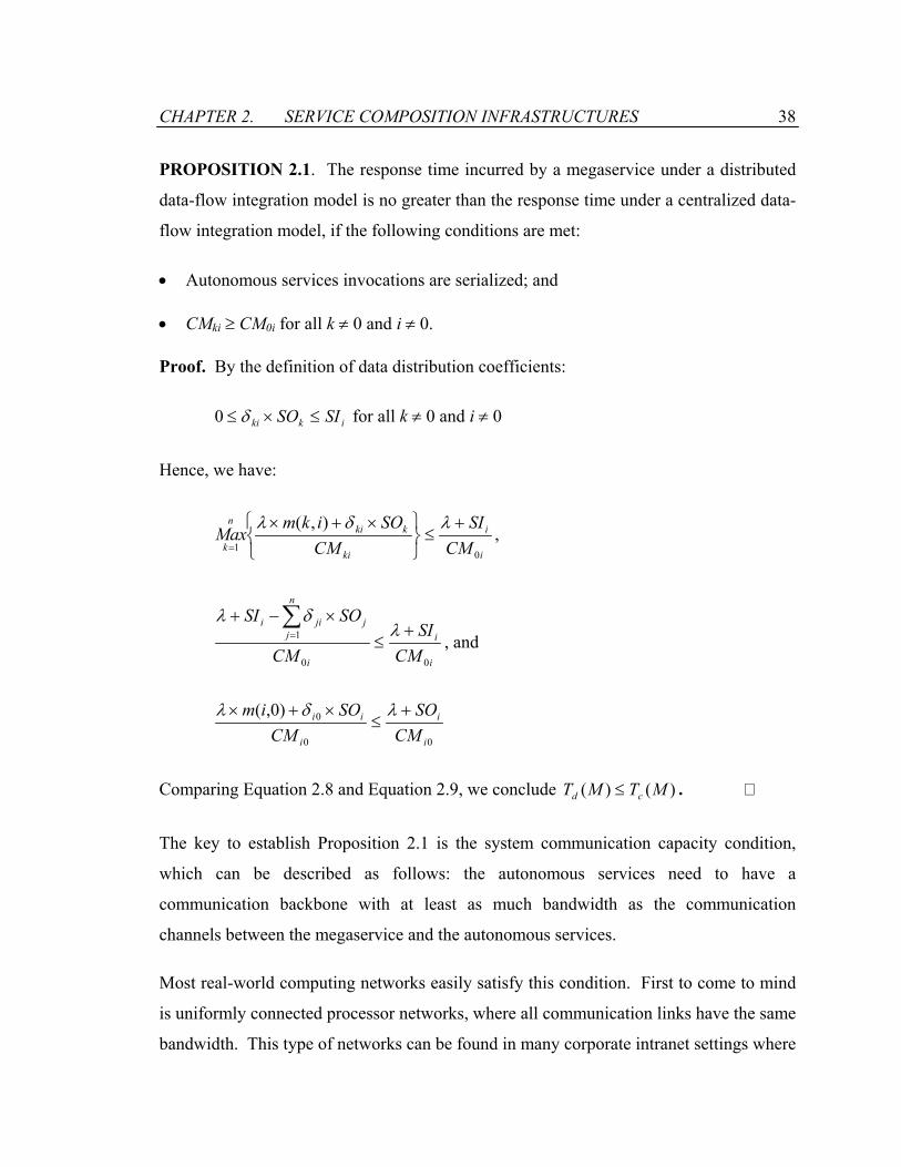
CHAPTER 2. SERVICE COMPOSITION INFRASTRUCTURES 38
PROPOSITION 2.1. The response time incurred by a megaservice under a distributed
data-flow integration model is no greater than the response time under a centralized data-
flow integration model, if the following conditions are met:
• Autonomous services invocations are serialized; and
• CMki ≥ CM0i for all k ≠ 0 and i ≠ 0.
Proof. By the definition of data distribution coefficients:
ikki SISO ≤×≤ δ0 for all k ≠ 0 and i ≠ 0
Hence, we have:
i
i
ki
kkin
k CMSI
CMSOikm
Max0
1
),( +≤
×+×
=
λδλ,
i
i
i
n
jjjii
CMSI
CM
SOSI
00
1 +≤
×−+ ∑= λ
δλ, and
00
0)0,(
i
i
i
ii
CMSO
CMSOim +
≤×+× λδλ
Comparing Equation 2.8 and Equation 2.9, we conclude T )()( MTM cd ≤ .
The key to establish Proposition 2.1 is the system communication capacity condition,
which can be described as follows: the autonomous services need to have a
communication backbone with at least as much bandwidth as the communication
channels between the megaservice and the autonomous services.
Most real-world computing networks easily satisfy this condition. First to come to mind
is uniformly connected processor networks, where all communication links have the same
bandwidth. This type of networks can be found in many corporate intranet settings where

CHAPTER 2. SERVICE COMPOSITION INFRASTRUCTURES 39
all computing facilities are connected on a uniform backbone. The second type is the
client-server network, where autonomous services reside on well-connected server farms
and the megaservices are clients accessing the servers from remote sites. The
communication capacity between the megaservice and the autonomous services may be
order of magnitude smaller than the communication capacities among the autonomous
services. The Internet and wireless service networks both can be categorized as this type
of networks.
Some typical communication parameters are shown in Table 2.1. These values will be
used to derive sample data points for the response times in the two integration models.
The Corporate Intranet A represents a typical Intranet computing environment where all
machines are fully connected via a high-speed switch. The Corporate Network B
represents an Intranet computing facility with remote access capability, where servers are
connected via a high-speed backbone to form a server farm and client machines connects
with the server farm remotely. The Wireless Network C represents a similar computing
environment as Corporate Network B except that client machines access the server farm
via wireless modems.
Let’s evaluate the response times for the example megaservice shown in Figure 2.4. The
megaservice involves four autonomous services and two processing routines, which are
carried out locally on the megaservice. The autonomous services are specified as
functions that take input data and generate output data. We assume that autonomous
services run on servers and megaservices are initiated from client machines. As an
example, the following parameters are assigned to the megaservice:
• The size of data item b is 1 MB and the sizes of other data items are 1 KB;
• The size of message header λ=128B;
• Each autonomous service can be processed in 100 ms; and
• The local-transform and local-processing routines can be processed in 100 ms.
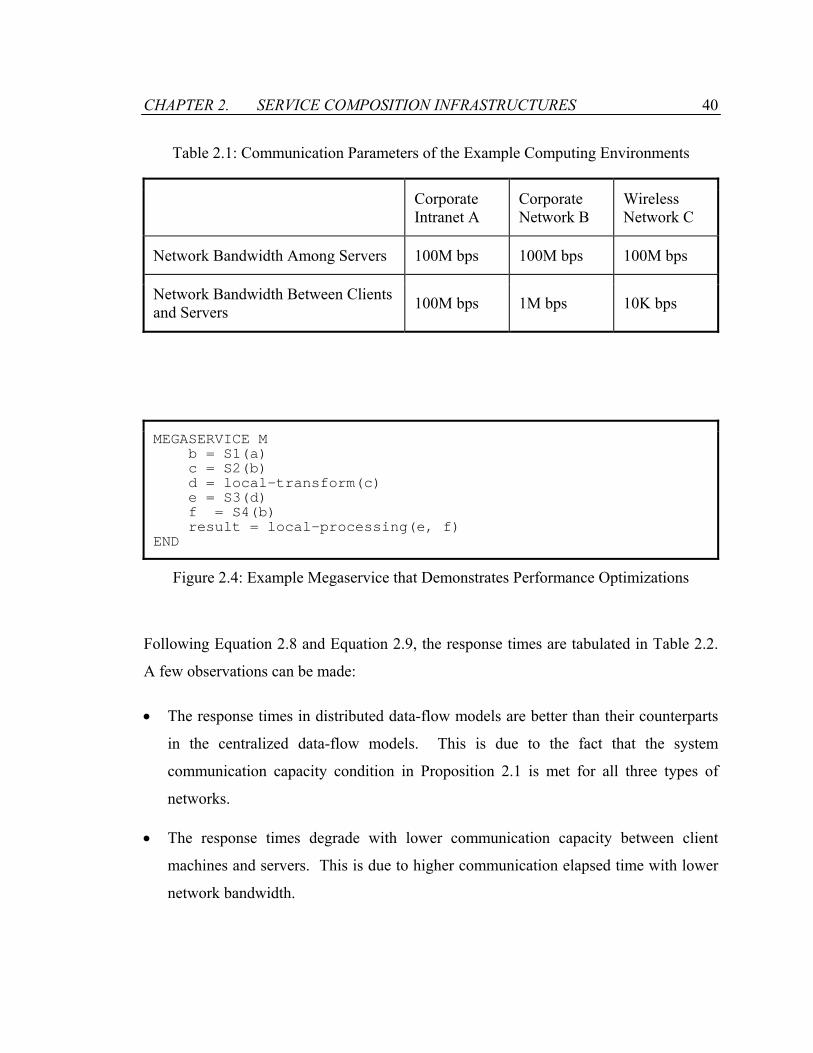
CHAPTER 2. SERVICE COMPOSITION INFRASTRUCTURES 40
Table 2.1: Communication Parameters of the Example Computing Environments
Corporate Intranet A
Corporate Network B
Wireless Network C
Network Bandwidth Among Servers 100M bps 100M bps 100M bps
Network Bandwidth Between Clients and Servers 100M bps 1M bps 10K bps
MEGASERVICE M b = S1(a) c = S2(b) d = local-transform(c) e = S3(d) f = S4(b) result = local-processing(e, f) END
Figure 2.4: Example Megaservice that Demonstrates Performance Optimizations
Following Equation 2.8 and Equation 2.9, the response times are tabulated in Table 2.2.
A few observations can be made:
• The response times in distributed data-flow models are better than their counterparts
in the centralized data-flow models. This is due to the fact that the system
communication capacity condition in Proposition 2.1 is met for all three types of
networks.
• The response times degrade with lower communication capacity between client
machines and servers. This is due to higher communication elapsed time with lower
network bandwidth.

CHAPTER 2. SERVICE COMPOSITION INFRASTRUCTURES 41
Table 2.2: Response Times of the Example Megaservice
Corporate Intranet A
Corporate Network B
Wireless Network C
Centralized Data-flow Model 840.5 ms 24,647 ms 2,405,288 ms
Distributed Data-flow Model 760.5 ms 804 ms 5,155 ms
• Network bandwidth between client machines and servers becomes a bottleneck in
centralized data-flow model, rendering the Wireless Network C inoperable to execute
the megaservice. On the other hand, the distributed data-flow model alleviates the
bottleneck by distributing network traffic within the server farm.
2.4.2 Parallel Invocation of Megaservices
Our objective in this section is to extend the response time analysis to the cases where
autonomous services can be invoked and executed in parallel, thus reducing the overall
response time of the megaservice. Compared to the sequential invocation scheme, the
parallel invocation scheme brings performance enhancement to both the distributed data-
flow model and the centralized data-flow model. The degree of enhancement depends on
many factors, such as the degree of parallelism in a megaservice, the process scheduling
algorithms, etc. Many of these factors may only be effective under one integration model
but not both, making a relevant comparison difficult. To compare the two data-flow
models, we make the assumption that the control-flows remain the same for the
integration models used, namely the partial order of autonomous services and
megaservice local processing are identical.
Our first task is to model the execution of a megaservice. It has been shown that timed
Petri nets are capable of modeling synchronization and concurrency [56, 61, 75]. We
model the execution of a megaservice as a timed marked graph (TMG), a well-known
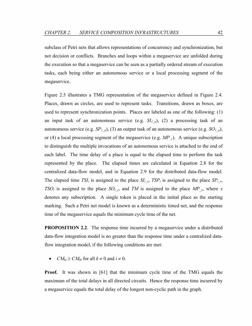
CHAPTER 2. SERVICE COMPOSITION INFRASTRUCTURES 42
subclass of Petri nets that allows representations of concurrency and synchronization, but
not decision or conflicts. Branches and loops within a megaservice are unfolded during
the execution so that a megaservice can be seen as a partially ordered stream of execution
tasks, each being either an autonomous service or a local processing segment of the
megaservice.
Figure 2.5 illustrates a TMG representation of the megaservice defined in Figure 2.4.
Places, drawn as circles, are used to represent tasks. Transitions, drawn as boxes, are
used to represent synchronization points. Places are labeled as one of the following: (1)
an input task of an autonomous service (e.g. SI1_a), (2) a processing task of an
autonomous service (e.g. SP1_a), (3) an output task of an autonomous service (e.g. SO1_a),
or (4) a local processing segment of the megaservice (e.g. MP_c). A unique subscription
to distinguish the multiple invocations of an autonomous service is attached to the end of
each label. The time delay of a place is equal to the elapsed time to perform the task
represented by the place. The elapsed times are calculated in Equation 2.8 for the
centralized data-flow model, and in Equation 2.9 for the distributed data-flow model.
The elapsed time TSIi is assigned to the place SIi_x, TSPi is assigned to the place SPi_x,
TSOi is assigned to the place SOi_x, and TM is assigned to the place MP_x, where x
denotes any subscription. A single token is placed in the initial place as the starting
marking. Such a Petri net model is known as a deterministic timed net, and the response
time of the megaservice equals the minimum cycle time of the net.
PROPOSITION 2.2. The response time incurred by a megaservice under a distributed
data-flow integration model is no greater than the response time under a centralized data-
flow integration model, if the following conditions are met:
• CMki ≥ CM0i for all k ≠ 0 and i ≠ 0.
Proof. It was shown in [61] that the minimum cycle time of the TMG equals the
maximum of the total delays in all directed circuits. Hence the response time incurred by
a megaservice equals the total delay of the longest non-cyclic path in the graph.

CHAPTER 2. SERVICE COMPOSITION INFRASTRUCTURES 43
MP_c SI3_d SP3_d SO3_d
MP_f
SI2_b SP2_b SO2_b
SI1_a SP1_a SO1_a
SI4_e SP4_e SO4_e
Figure 2.5: Timed Marked Graph Representation of the Example Megaservice
Consider two timed marked graphs: TMGc and TMGd, representing megaservice
executions under the centralized-data flow model and the distributed data-flow model,
respectively. By construction, TMGc and TMGd have the same structure, i.e. the same set
of places, transitions, arcs and initial markings. They differ only in the time delays that
are assigned to the places. Follow the proof in Proposition 2.1, the times TM, TSI, TSP,
and TSO under the centralized data-flow model are greater than or equal to those times
under the distributed data-flow model, when the communication capacity condition (i.e.,
CMki ≥ CM0i for all k ≠ 0 and i ≠ 0) is met. Let τpc and τp
d represent the time delays of a
place p in TMGc and TMGd. Thus, τpc ≥ τp
d, if CMki ≥ CM0i for all k ≠ 0 and i ≠ 0.
Let’s denote the longest non-cyclic path in TMGd as P. The response time for the
distributed control model equals the total delay of the path P in TMGd, which is
. The response time for the centralized model is at least as long as the total
delay for the same path P in TMGc, which is
∑ ∈Ppdpτ
∑ ∈Ppcpτ . Since ∑∑ ∈∈
≥Pp
dpPp
cp ττ , the
proposition holds.

CHAPTER 2. SERVICE COMPOSITION INFRASTRUCTURES 44
Clearly, Proposition 2.2 covers Proposition 2.1, as serialized invocation is a special case
of parallel invocation. Therefore, we have proved that the distributed data-flow
integration model has better response time performance than the centralized data-flow
integration model if the system communication capacity condition is met.
2.5 Performance Impact of Control-flows
When the control message size is comparable to the data message size, the impact of
control-flows on the performance of megaservices needs to be accounted for. Different
control and data messages are involved for service invocations under the Centralized
Control-flow Centralized Data-flow (1C1D) and the Centralized Control-flow Distributed
Data-flow (1CnD) models. Under the 1C1D model, a service invocation consists of two
messages: a service invocation request sent from the megaservice containing the input
data for the invocation, and a reply message returned from the autonomous service
containing the result of the invocation. Under the 1CnD model, a service invocation is
broken up into three phases. During the data preparation, the megaservice informs the
autonomous service to prepare the necessary input data. During the invocation phase, the
megaservice sends a service invocation request to the autonomous service. And during
the reply phase, the autonomous service acknowledges the completion of its tasks.
Let’s compare the performance of the two integration models for the service invocation
shown in Figure 2.6. The autonomous service S is invoked with an input data element,
and generates an output data element. The input data element was previously produced
by the autonomous service Sinput. The output data element will be utilized by another
autonomous service. As the execution times of the autonomous service under the 1C1D
and the 1CnD models remain the same, the performance comparison of the two models
can be compared based on the communication cost.

CHAPTER 2. SERVICE COMPOSITION INFRASTRUCTURES 45
For simplicity, we model the cost of messages as a linear function to their sizes.
Furthermore, we assume a control message has a size of λc, a data message containing the
data element has a size of λd, and the combined message have a size of (λc+λd) when data
and control are sent together. Under the 1C1D model, the messaging cost for the service
invocation request is (λc+λd), and the cost for the reply message is (λc+λd) as well.
Therefore, the cost for the service invocation is (2λc+2λd). For the 1CnD model, five
messages are involved for the service invocation: (1) the megaservice first sends a control
message to the autonomous service Sinput to establish a data-flow with the autonomous
service S; (2) The autonomous service Sinput sends the necessary input data to the
autonomous service S using a data message; (3) The autonomous service Sinput notifies the
megaservice the completion of the data transfer; (4) The megaservice sends a service
invocation request to the autonomous service with a control message; and (5) Finally, the
autonomous service S completes its processing and acknowledges the megaservice with a
control message. Overall, there are four control messages and one data message involved
with the service invocation. The total cost is (4λc+λd).
Figure 2.7 illustrates the messaging costs for the service invocation under the 1C1D and
the 1CnD models. The control message size λc is treated as a constant factor. The x-axis
represents the relative size of the data message with respect to λc, and the y-axis measures
the messaging cost in terms of λc. First, we observe that larger data message sizes
attribute to higher communication costs for service invocations under both models.
Comparing the two models, the 1C1D model performs better than the 1CnD model when
the data message is the same as the control message in size. However, the
communication cost for 1C1D model scales up much faster than for the 1CnD model.
The 1CnD model quickly outperforms the 1C1D model with a larger data message size.
For our example, the 1CnD model has better performance if the data message is at least
twice as large as the control message. As most autonomous services are expected to
involve fair amount of data communications, the 1CnD model is a preferred model for
service composition.
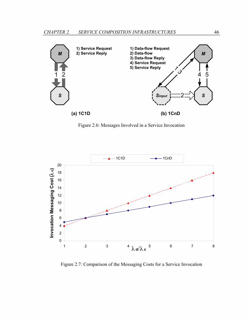
CHAPTER 2. SERVICE COMPOSITION INFRASTRUCTURES 46
M
S
1
M
Sinput S
(a) 1C1D (b) 1CnD
3
2
4 51 2
1) Service Request2) Service Reply
1) Data-flow Request2) Data-flow3) Data-flow Reply4) Service Request5) Service Reply
Figure 2.6: Messages Involved in a Service Invocation
0
2
4
6
8
10
12
14
16
18
20
1 2 3 4 5 6 7 8λ d/λ c
Invo
catio
n M
essa
ging
Cos
t (λ
c)
1C1D 1CnD
Figure 2.7: Comparison of the Messaging Costs for a Service Invocation
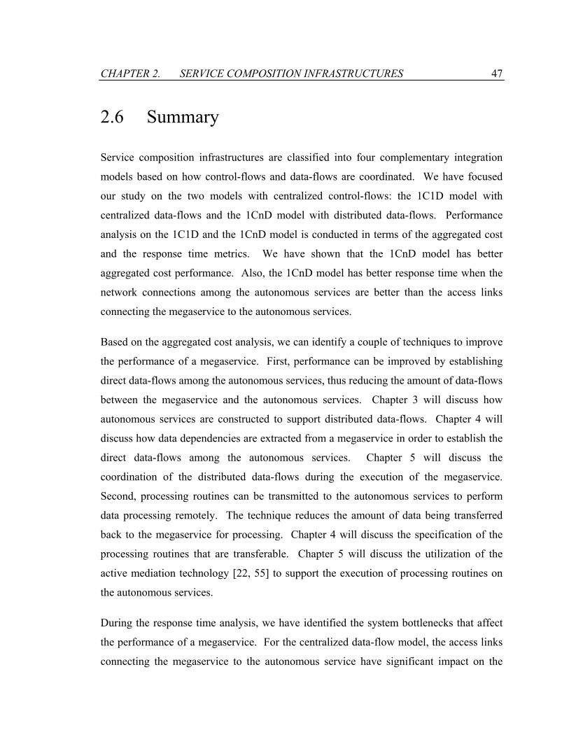
CHAPTER 2. SERVICE COMPOSITION INFRASTRUCTURES 47
2.6 Summary
Service composition infrastructures are classified into four complementary integration
models based on how control-flows and data-flows are coordinated. We have focused
our study on the two models with centralized control-flows: the 1C1D model with
centralized data-flows and the 1CnD model with distributed data-flows. Performance
analysis on the 1C1D and the 1CnD model is conducted in terms of the aggregated cost
and the response time metrics. We have shown that the 1CnD model has better
aggregated cost performance. Also, the 1CnD model has better response time when the
network connections among the autonomous services are better than the access links
connecting the megaservice to the autonomous services.
Based on the aggregated cost analysis, we can identify a couple of techniques to improve
the performance of a megaservice. First, performance can be improved by establishing
direct data-flows among the autonomous services, thus reducing the amount of data-flows
between the megaservice and the autonomous services. Chapter 3 will discuss how
autonomous services are constructed to support distributed data-flows. Chapter 4 will
discuss how data dependencies are extracted from a megaservice in order to establish the
direct data-flows among the autonomous services. Chapter 5 will discuss the
coordination of the distributed data-flows during the execution of the megaservice.
Second, processing routines can be transmitted to the autonomous services to perform
data processing remotely. The technique reduces the amount of data being transferred
back to the megaservice for processing. Chapter 4 will discuss the specification of the
processing routines that are transferable. Chapter 5 will discuss the utilization of the
active mediation technology [22, 55] to support the execution of processing routines on
the autonomous services.
During the response time analysis, we have identified the system bottlenecks that affect
the performance of a megaservice. For the centralized data-flow model, the access links
connecting the megaservice to the autonomous service have significant impact on the

CHAPTER 2. SERVICE COMPOSITION INFRASTRUCTURES 48
megaservice performance. On the other hand, for the distributed data-flow model, the
network connections among the autonomous services are more relevant to the
megaservice performance. These findings help guide building appropriate system
architectures for the service composition infrastructure.

Chapter 3
Autonomous Services
An autonomous service is a process that involves one or more software applications
along with the domain data they operate on. The autonomous service functions as a
server that waits for service requests, and the client utilizes the autonomous service by
making service requests. To respond to the requests, the service invokes appropriate
software applications. The result of the invocation returns desired information to the
client.
Composition of autonomous services requires homogeneity among the services. A
standard mechanism is needed to utilize the functionalities provided by the services.
However, heterogeneity is often implied for the different types of operating system,
hardware platform, data representation format that are used to support the services. The
Internet is a good example of the type of heterogeneity we encounter in today’s
computing environments. There are dozens of operating systems, hundreds of hardware
platforms, and thousands of data representation formats. An access method needs to be
defined for autonomous services in order to bridge the difference between the
homogeneous access requirement and the heterogeneous environments.

CHAPTER 3. AUTONOMOUS SERVICES 50
To enable distribution of data-flows, autonomous services need to support direct data
communications. This chapter introduces a metamodel that separates the data
communications from the control processing of the services. The metamodel allows the
services to be centrally controlled, while their data communications are distributed.
Based on the metamodel, an access protocol for autonomous services is defined to enable
homogeneous access to the services. Finally, this chapter illustrates the process by which
a software application can be wrapped into an autonomous service.
3.1 Autonomous Service Metamodel
The metamodel offers a description of all properties of autonomous services that are
independent of the states of the services. The metamodel includes the following four
models:
• Hierarchical Model: The metamodel specifies the hierarchical composition of the
services. The hierarchical model describes the internal layers of the services as well
as the interconnections among the layers.
• Data Model: The metamodel defines the data model for the services. Based on the
data model, information can be exchanged among the services using a uniform
representation.
• Service Interaction Model: The metamodel specifies the interface through which the
services are accessed. The metamodel, together with a messaging protocol, provides
a standard mechanism to interact with the services.
• Structural Model: The metamodel specifies the functional components of the services
and their interdependencies. The structural model serves as a blueprint for building
new services.
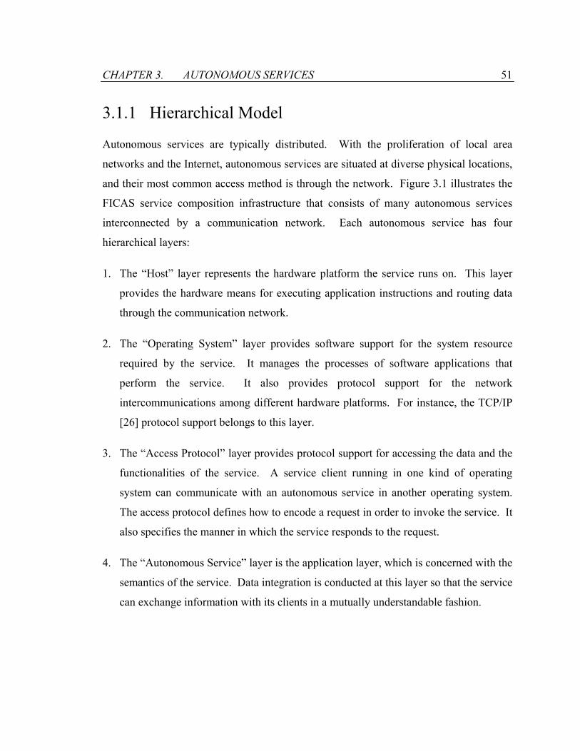
CHAPTER 3. AUTONOMOUS SERVICES 51
3.1.1 Hierarchical Model
Autonomous services are typically distributed. With the proliferation of local area
networks and the Internet, autonomous services are situated at diverse physical locations,
and their most common access method is through the network. Figure 3.1 illustrates the
FICAS service composition infrastructure that consists of many autonomous services
interconnected by a communication network. Each autonomous service has four
hierarchical layers:
1. The “Host” layer represents the hardware platform the service runs on. This layer
provides the hardware means for executing application instructions and routing data
through the communication network.
2. The “Operating System” layer provides software support for the system resource
required by the service. It manages the processes of software applications that
perform the service. It also provides protocol support for the network
intercommunications among different hardware platforms. For instance, the TCP/IP
[26] protocol support belongs to this layer.
3. The “Access Protocol” layer provides protocol support for accessing the data and the
functionalities of the service. A service client running in one kind of operating
system can communicate with an autonomous service in another operating system.
The access protocol defines how to encode a request in order to invoke the service. It
also specifies the manner in which the service responds to the request.
4. The “Autonomous Service” layer is the application layer, which is concerned with the
semantics of the service. Data integration is conducted at this layer so that the service
can exchange information with its clients in a mutually understandable fashion.
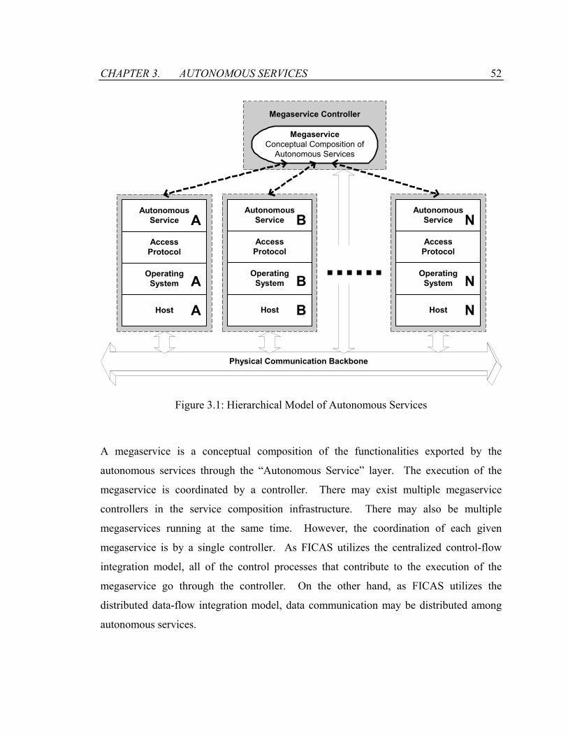
CHAPTER 3. AUTONOMOUS SERVICES 52
AutonomousService
AccessProtocol
OperatingSystem
Host
A
A
A
AutonomousService
AccessProtocol
OperatingSystem
Host
N
N
N
Physical Communication Backbone
MegaserviceConceptual Composition of
Autonomous Services
AutonomousService
AccessProtocol
OperatingSystem
Host
B
B
B
Megaservice Controller
......
Figure 3.1: Hierarchical Model of Autonomous Services
A megaservice is a conceptual composition of the functionalities exported by the
autonomous services through the “Autonomous Service” layer. The execution of the
megaservice is coordinated by a controller. There may exist multiple megaservice
controllers in the service composition infrastructure. There may also be multiple
megaservices running at the same time. However, the coordination of each given
megaservice is by a single controller. As FICAS utilizes the centralized control-flow
integration model, all of the control processes that contribute to the execution of the
megaservice go through the controller. On the other hand, as FICAS utilizes the
distributed data-flow integration model, data communication may be distributed among
autonomous services.
CHAPTER 3. AUTONOMOUS SERVICES 53
3.1.2 Data Model
Autonomous services collaborate by exchanging information. A project-scheduling
service may need to obtain activity and duration information from a modeling service and
sends the analysis results to an information retrieval service. The heterogeneity in the
computing environment implies different data representations for different services. It is
essential to have a reliable, simple and universally deployed data exchange model for
effective interoperations of the services. The exchange model serves as the proxy for an
autonomous service. Data destined to a different service is mapped from the internal
representation to the exchange model before delivery, and data received from another
service is mapped back to the internal representation before usage.
In software integration, applications typically need to map their data models and formats
to other applications, requiring what is often called ‘legacy wrapping’ [43]. There are
several problems associated with this approach. First, every connection between two
applications will most likely require custom programming. For each pair of applications,
a custom wrapper needs to be built. If many applications are involved, substantial
programming effort will be needed. Furthermore, the maintenance of the custom
wrappers is expensive. Any data model and format changes in an application will affect
all wrappers that have one end connecting to the application. Also, data corruption and
parameter mismatch can cause unpredictable results, and debugging and error handling
become difficult since many wrappers need to be looked at simultaneously. Because of
its fragility, legacy wrapping incurs high maintenance cost.
The notion of objects can be effectively utilized for communicating information between
various applications, as demonstrated previously for mediators [19, 24, 69-71]. When the
underlying resources are modeled as objects, the connections among the resources can be
encapsulated. The basic unit for data communication within FICAS is an object called
data element. A data element consists of a name and a structure, which itself may be a
tuple over other defined data elements. Definition 3.1 provides the formal definition of
CHAPTER 3. AUTONOMOUS SERVICES 54
the data element using the recursive constructor that is commonly used in the field of data
modeling [86]:
DEFINITION 3.1: Let V be the set of data elements, N be the set of names, and S be the
set of structures. Then:
1.
A valid data element consists of a name and a defined structure;
VsnSsNn >∈⇒<∈∧∈ ,
2. Sk ∈ζζ ,,1 L , where kζζ ,,1 L represents existing atomic structures.
3. SVVV ∈×⇒⊆
A tuple over defined data elements is a valid structure.
A data element is represented as a tree. The name of the data element is the root of the
tree, and the structure of the data element is the child of the root. In the case of an atomic
structure, there is only one child node, as shown in Figure 3.2(a). In the case where the
structure is a tuple over defined data elements, each defined data element is a child node
of the root, as shown in Figure 3.3(a). Recursively, each defined data element is
represented as a sub-tree.
Data elements, as defined, can be encoded in many different data formats. We choose
XML to represent data elements because of their structural similarity [88]. As a simple
textual language, XML is quickly gaining popularity for data representation and
exchange on the Web. XML is a meta-markup language that consists of a set of rules for
creating semantic tags used to describe data. An XML element is made up of a start tag,
an end tag, and content in between. The start and end tags describe the content within the
tags, which is considered the value of the element. The tags of the XML element
represent the name of the data element. The value of the XML element represents the
CHAPTER 3. AUTONOMOUS SERVICES 55
sub-structure of the data element. In essence, XML provides a mechanism to describe the
hierarchy of elements that forms the data element.
The mapping between a data element and its XML representation is straightforward. The
name of a data element maps into a pair of start and end tags. The structure of the data
element maps into the value enclosed between the XML tags. Figure 3.2 shows a simple
data element and its corresponding XML representation. The data element contains a
name and an atomic structure. The name is “STRING”, and the atomic structure is a
string with the value “Hello World!”. The corresponding XML representation of the data
element therefore uses “<STRING>” and “</STRING>” as the start tag and the end tag,
respectively. Between the tags, the string value corresponds to the atomic structure of the
data element.
Figure 3.3 shows a composite data element and its corresponding XML representation.
The name of the data element is “RECORD”, which serves as the start tag and the end tag
of its corresponding XML representation. The structure of the data element is a tuple of
two data elements, which themselves are represented as XML elements with tag names of
“NAME” and “PICTURE”, respectively. The string value “John Doe” is directly mapped
as the content of the XML element tagged “NAME”. The picture is encoded into a valid
XML string that serves as the content of the XML element tagged “PICTURE”. A
matching decoding scheme converts the encoded XML string back into a picture when
the data element is used. The encoding and decoding schemes are specific to the service
composition infrastructure and should be shared by all autonomous services within the
infrastructure.
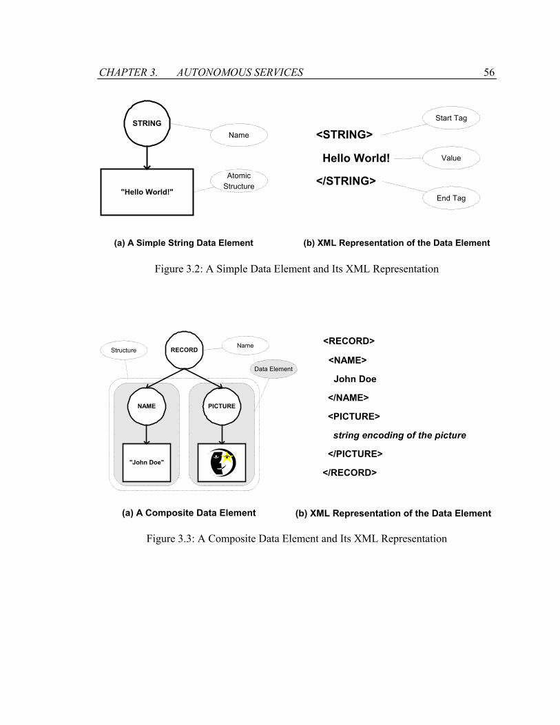
CHAPTER 3. AUTONOMOUS SERVICES 56
STRING
"Hello World!"
Name
AtomicStructure
Start Tag
<STRING>
</STRING>
Hello World!
End Tag
Value
(a) A Simple String Data Element (b) XML Representation of the Data Element
Figure 3.2: A Simple Data Element and Its XML Representation
RECORD
"John Doe"
Data Element
Structure<RECORD>
John Doe
<NAME>
(a) A Composite Data Element (b) XML Representation of the Data Element
NAME PICTURE </NAME>
<PICTURE>
string encoding of the picture
</PICTURE>
</RECORD>
Name
Figure 3.3: A Composite Data Element and Its XML Representation
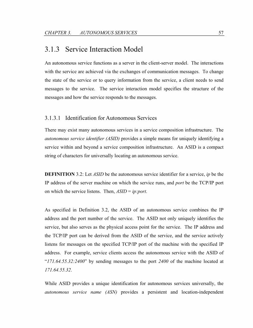
CHAPTER 3. AUTONOMOUS SERVICES 57
3.1.3 Service Interaction Model
An autonomous service functions as a server in the client-server model. The interactions
with the service are achieved via the exchanges of communication messages. To change
the state of the service or to query information from the service, a client needs to send
messages to the service. The service interaction model specifies the structure of the
messages and how the service responds to the messages.
3.1.3.1 Identification for Autonomous Services
There may exist many autonomous services in a service composition infrastructure. The
autonomous service identifier (ASID) provides a simple means for uniquely identifying a
service within and beyond a service composition infrastructure. An ASID is a compact
string of characters for universally locating an autonomous service.
DEFINITION 3.2: Let ASID be the autonomous service identifier for a service, ip be the
IP address of the server machine on which the service runs, and port be the TCP/IP port
on which the service listens. Then, ASID = ip:port.
As specified in Definition 3.2, the ASID of an autonomous service combines the IP
address and the port number of the service. The ASID not only uniquely identifies the
service, but also serves as the physical access point for the service. The IP address and
the TCP/IP port can be derived from the ASID of the service, and the service actively
listens for messages on the specified TCP/IP port of the machine with the specified IP
address. For example, service clients access the autonomous service with the ASID of
“171.64.55.32:2400” by sending messages to the port 2400 of the machine located at
171.64.55.32.
While ASID provides a unique identification for autonomous services universally, the
autonomous service name (ASN) provides a persistent and location-independent

CHAPTER 3. AUTONOMOUS SERVICES 58
identification for services within a service composition infrastructure. Each service is
assigned a unique string as its ASN. Using an appropriate mapping mechanism, an
autonomous service referred by its ASN can dynamically look up its ASID. For instance,
“WeatherService” can be assigned as the ASN of an autonomous service, whose ASID is
“171.64.55.32:2400”. The use of the ASN provides an added level of indirection that
allows autonomous services to be seamlessly relocated. The specification of
megaservices uses the ASN to refer to the autonomous service, and the execution of the
megaservices uses the ASID to interact with the autonomous service.
3.1.3.2 Control-flows and Data-flows
Message is the basic means of communication within a service composition
infrastructure. A message semantically consists of a source, a destination, and a message
body. The source identifies where the message is originated. It also serves as the reply
address if there is any returning communication. The destination identifies the service to
where the message is targeted. The message body contains the information to be
delivered and the actions to be performed by the target service. A set of messages that
works together to accomplish a certain task forms a flow. For instance, a pair of the
service request and reply message may be considered a flow, since all the messages
together are necessary to accomplish a service invocation.
There are two types of messages: control messages and data messages. The control
messages are mostly short messages that manage the states of autonomous services. The
data messages are mostly used for transporting large data contents to autonomous
services for processing. Correspondingly, there are two types of flows: control-flows and
data-flows. A control-flow consists of control messages that coordinate the services in
order to accomplish a task. A data-flow, on the other hand, consists of data messages that
transmit data among the services to accomplish a task.
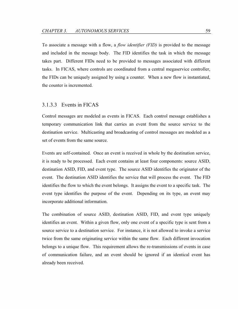
CHAPTER 3. AUTONOMOUS SERVICES 59
To associate a message with a flow, a flow identifier (FID) is provided to the message
and included in the message body. The FID identifies the task in which the message
takes part. Different FIDs need to be provided to messages associated with different
tasks. In FICAS, where controls are coordinated from a central megaservice controller,
the FIDs can be uniquely assigned by using a counter. When a new flow is instantiated,
the counter is incremented.
3.1.3.3 Events in FICAS
Control messages are modeled as events in FICAS. Each control message establishes a
temporary communication link that carries an event from the source service to the
destination service. Multicasting and broadcasting of control messages are modeled as a
set of events from the same source.
Events are self-contained. Once an event is received in whole by the destination service,
it is ready to be processed. Each event contains at least four components: source ASID,
destination ASID, FID, and event type. The source ASID identifies the originator of the
event. The destination ASID identifies the service that will process the event. The FID
identifies the flow to which the event belongs. It assigns the event to a specific task. The
event type identifies the purpose of the event. Depending on its type, an event may
incorporate additional information.
The combination of source ASID, destination ASID, FID, and event type uniquely
identifies an event. Within a given flow, only one event of a specific type is sent from a
source service to a destination service. For instance, it is not allowed to invoke a service
twice from the same originating service within the same flow. Each different invocation
belongs to a unique flow. This requirement allows the re-transmissions of events in case
of communication failure, and an event should be ignored if an identical event has
already been received.

CHAPTER 3. AUTONOMOUS SERVICES 60
3.1.3.4 Data Container and Data Map
The entities that hold data elements in an autonomous service are called data containers.
The service consumes the data elements from its input data container, and produces and
puts the data elements into its output data container. The data containers are explicit
groupings of the data elements associated with the service. Figure 3.4 illustrates the
structure of a data container. The data container uses the flow identifier (FID) and the
position index (PID) as indices for the data elements. The FID identifies the flow to
which a data element belongs, and the PID distinguishes a data element when multiple
data elements are involved in the same flow. The combination of FID and PID can
therefore uniquely identifies a data element in the data container. For instance, a flow,
identified by FID “12345”, involves three data elements. The three data elements are
distinguished by their unique PIDs, “0”, “1”, and “2”.
Two autonomous services exchange data elements by establishing a data map from the
output data container of one service to the input data container of the other service. If the
service s2 needs a data element produced by the service s1, then a data map needs to be
established from s1 to s2.
Flow Identifier (FID) Position Index (PID) Data Element12345 0
12345 1
12345 2
12456 0
12577 0
12577 1
… … …
Figure 3.4: Structural View of the Data Container
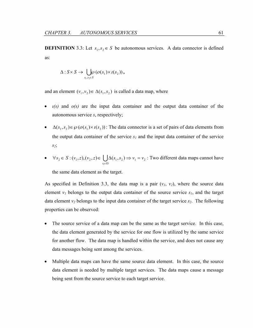
CHAPTER 3. AUTONOMOUS SERVICES 61
DEFINITION 3.3: Let Sss ∈21 , be autonomous services. A data connector is defined
as:
USss
ssSS∈
×℘→×∆21 ,
21 ))()((: ιο ,
and an element is called a data map, where ),(),( 2121 ssvv ∆∈
• ι(s) and ο(s) are the input data container and the output data container of the
autonomous service s, respectively;
• ))()((),( 2121 ssss ιο ×∈℘∆ : The data connector is a set of pairs of data elements from
the output data container of the service s1 and the input data container of the service
s2;
• : Two different data maps cannot have
the same data element as the target.
UΩ∈
=⇒∆∈∈∀1
2121212 ),(),(),,(:s
vvsszvzvSs
As specified in Definition 3.3, the data map is a pair (v1, v2), where the source data
element v1 belongs to the output data container of the source service s1, and the target
data element v2 belongs to the input data container of the target service s2. The following
properties can be observed:
• The source service of a data map can be the same as the target service. In this case,
the data element generated by the service for one flow is utilized by the same service
for another flow. The data map is handled within the service, and does not cause any
data messages being sent among the services.
• Multiple data maps can have the same source data element. In this case, the source
data element is needed by multiple target services. The data maps cause a message
being sent from the source service to each target service.
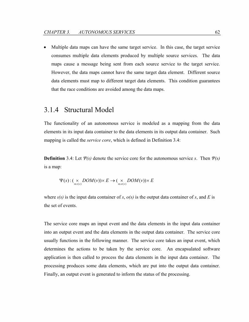
CHAPTER 3. AUTONOMOUS SERVICES 62
• Multiple data maps can have the same target service. In this case, the target service
consumes multiple data elements produced by multiple source services. The data
maps cause a message being sent from each source service to the target service.
However, the data maps cannot have the same target data element. Different source
data elements must map to different target data elements. This condition guarantees
that the race conditions are avoided among the data maps.
3.1.4 Structural Model
The functionality of an autonomous service is modeled as a mapping from the data
elements in its input data container to the data elements in its output data container. Such
mapping is called the service core, which is defined in Definition 3.4:
Definition 3.4: Let Ψ(s) denote the service core for the autonomous service s. Then Ψ(s)
is a map:
EvDOMEvDOMssvsv
××→××Ψ∈∈
))(())((:)()()( οι
where ι(s) is the input data container of s, ο(s) is the output data container of s, and E is
the set of events.
The service core maps an input event and the data elements in the input data container
into an output event and the data elements in the output data container. The service core
usually functions in the following manner. The service core takes an input event, which
determines the actions to be taken by the service core. An encapsulated software
application is then called to process the data elements in the input data container. The
processing produces some data elements, which are put into the output data container.
Finally, an output event is generated to inform the status of the processing.

CHAPTER 3. AUTONOMOUS SERVICES 63
The service core by definition is stateless. Given the input data elements and the input
event, the output data elements and the output event can be determined. The state of the
service core has no effect on the functionality provided by the service core. However the
interactions with autonomous services may be stateful for many megaservices. For
instance, an autonomous service that manages a shopping cart needs to handle multiple
user sessions, each of which contains state information. This requires the service to
provide state management for the encapsulated software application. To implement state-
aware autonomous service, the service core needs to pass along its state information as
data elements. The key is to design the appropriate context that describes the current
state of the encapsulated software application [42, 50]. The context can be saved as a
data element and returned to the service client. The data element is then used to restore
the context during the future interactions with the service.
An autonomous service is formed by tying together a service core with the components
that manage events and data elements. As shown in Figure 3.5, the autonomous service
consists of an input event queue, an output event queue, an input data container, an output
data container, and a service core:
• The executions of autonomous services are controlled by events. The event queues
handle the difference in the rates at which events are received and processed. Each
event queue uses its own thread. The input event queue buffers the incoming events
to be processed by the service core, and the output event queue buffers the outgoing
events generated by the service core. FICAS uses the first-come-first-serve (FIFO)
queues, where events are processed in the order by which they are received.
• The data containers manage the data elements for the autonomous services. The input
data container hosts the data elements to be processed by the service core, and the
output data container stores the data elements produced by the service core. In
addition, the data containers handle the exchange of data elements between two
autonomous services. The output data container can look up a data element and
transfer it to the input data container of another service.

CHAPTER 3. AUTONOMOUS SERVICES 64
Data-flow
Control-flow
Input Data Container
Output Data Container
Input Event Queue
Output Event Q
ueueService Core
Figure 3.5: Structural Model of an Autonomous Service
• The service core resides in the center of the autonomous service. It processes events
in the input event queue one at a time. The event specifies the actions to be taken by
the autonomous service. Based on the event, the service core processes the
corresponding input data elements in the input data container using the encapsulated
software application. The resulting data elements are put into the output data
container, and a response event is put into the output event queue.
The key characteristic of the FICAS autonomous service model is the explicit separation
of control-flow and data-flow. For control-flow, the autonomous service is primarily
concerned about the event processing and the state management of the service core. For
data-flow, the autonomous service is primarily concerned about the exchange of data
elements between the data containers and the processing of the data elements by the
service core. The control-flows and the data-flows are managed by asynchronous
components of the autonomous service. While each component uses its own thread, the
service core ties together the components into a coordinated entity.
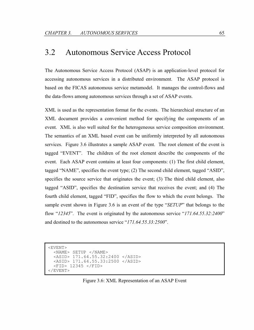
CHAPTER 3. AUTONOMOUS SERVICES 65
3.2 Autonomous Service Access Protocol
The Autonomous Service Access Protocol (ASAP) is an application-level protocol for
accessing autonomous services in a distributed environment. The ASAP protocol is
based on the FICAS autonomous service metamodel. It manages the control-flows and
the data-flows among autonomous services through a set of ASAP events.
XML is used as the representation format for the events. The hierarchical structure of an
XML document provides a convenient method for specifying the components of an
event. XML is also well suited for the heterogeneous service composition environment.
The semantics of an XML based event can be uniformly interpreted by all autonomous
services. Figure 3.6 illustrates a sample ASAP event. The root element of the event is
tagged “EVENT”. The children of the root element describe the components of the
event. Each ASAP event contains at least four components: (1) The first child element,
tagged “NAME”, specifies the event type; (2) The second child element, tagged “ASID”,
specifies the source service that originates the event; (3) The third child element, also
tagged “ASID”, specifies the destination service that receives the event; and (4) The
fourth child element, tagged “FID”, specifies the flow to which the event belongs. The
sample event shown in Figure 3.6 is an event of the type “SETUP” that belongs to the
flow “12345”. The event is originated by the autonomous service “171.64.55.32:2400”
and destined to the autonomous service “171.64.55.33:2500”.
<EVENT> <NAME> SETUP </NAME> <ASID> 171.64.55.32:2400 </ASID> <ASID> 171.64.55.33:2500 </ASID> <FID> 12345 </FID> </EVENT>
Figure 3.6: XML Representation of an ASAP Event

CHAPTER 3. AUTONOMOUS SERVICES 66
Traditionally, function calls are used to invoke services in the client-server architecture.
A request is made to a server along with the parameters to support the request, and a
reply is returned to the client along with the result data. The ASAP protocol splits the
simple function call into multiple phases to support data-flow distribution and to provide
parallelism. The divisions are the initialization, invocation, termination, and data
management phases. Since each of these phases behaves differently, different events are
used to manage each phase. The events are categorized accordingly into the following
four groups:
1. Initialization and termination of autonomous services;
2. Invocation of autonomous services;
3. Management of the data-flows between autonomous services; and
4. Auxiliary functions.
The ASAP protocol defines the syntax and semantics of the events. It also specifies the
expected actions taken by the autonomous services responding to the events.
3.2.1 Initialization and Termination Events
Four events belongs to this group: SETUP, SETUPREPLY, TERMINATE, and
TERMINATEREPLY. The pair of SETUP and SETUPREPLY events are used to
initialize autonomous services, and the pair of TERMINATE and TERMINATEREPLY
events are used to terminate autonomous services. Table 3.1 shows the syntax of the
initialization and the termination events.
The SETUP event requests the initialization of an autonomous service. The event type is
specified in the “NAME” element. The source-service field specifies the source service
that originates the initialization request. The destination-service field specifies the target
service to be initialized. The flow-id field specifies the flow to which the request

CHAPTER 3. AUTONOMOUS SERVICES 67
belongs. Upon reception of the SETUP event, the target service initializes itself and
prepares the necessary system resources for the future invocations of the service. The
target service expects that any parameters necessary for the initialization can be found in
the input data container of the service. The parameters should be prepared in advance of
the SETUP event. To initialize the service, the initialization parameters are fetched from
the input data container with the flow identifier flow-id. The initialization routine of the
service core is called. The output data elements are generated into the output data
container when the initialization is completed. They are assigned with the flow
identifiers flow-id.
Table 3.1: Initialization and Termination Events in the ASAP Protocol
Event Type Event Syntax
SETUP
<EVENT> <NAME> SETUP </NAME> <ASID> source-service </ASID> <ASID> destination-service </ASID> <FID> flow-id </FID> </EVENT>
SETUPREPLY
<EVENT> <NAME> SETUPREPLY </NAME> <ASID> source-service </ASID> <ASID> destination-service </ASID> <FID> flow-id </FID> <REPLY> reply </REPLY> </EVENT>
TERMINATE
<EVENT> <NAME> TERMINATE </NAME> <ASID> source-service </ASID> <ASID> destination-service </ASID> <FID> flow-id </FID> </EVENT>
TERMINATEREPLY
<EVENT> <NAME> TERMINATEREPLY </NAME> <ASID> source-service </ASID> <ASID> destination-service </ASID> <FID> flow-id </FID> <REPLY> reply </REPLY> </EVENT>
CHAPTER 3. AUTONOMOUS SERVICES 68
The SETUPREPLY event is used by the autonomous service to respond to the SETUP
event. The source-service and destination-service fields of the SETUPREPLY event are
swapped with those in the corresponding SETUP event. The source-service of the
SETUP event becomes the destination-service of the SETUPREPLY event, and the
destination-service of the SETUP event becomes the source-service of the
SETUPREPLY event. The flow-id of the SETUPREPLY event is identical to that of the
SETUP event. The reply field contains the information about the status of the service
initialization. For instance, the string “SUCCESS” indicates the successful initialization
of the service, and the string “FAILURE” indicates that the initialization has failed.
Symmetrical to the SETUP and the SETUPREPLY events used for service initialization,
the TERMINATE and TERMINATEREPLY events are used for service termination.
The TERMINATE event requests the termination of an autonomous service. The source-
service field specifies the source service that originates the termination request. The
destination-service field specifies the target service to be terminated. The flow-id field
specifies the flow to which the request belongs. Upon reception of the TERMINATE
event, the target service releases the system resources allocated for the service
invocations. The termination routine of the service core is then called. The parameters
for the termination routine should be prepared in the input data container in advance of
the termination request. The parameters are looked up with the flow identifier flow-id.
Garbage collection is conducted at the end to clear the temporary data elements hosted in
the data containers. As the result of the service termination, the target service generates a
TERMINATEREPLY event to inform the source service that originates the
TERMINATE event.
3.2.2 Invocation Events
Two events are used to support the invocation of autonomous services: INVOKE and
INVOKEREPLY, as shown in Table 3.2.

CHAPTER 3. AUTONOMOUS SERVICES 69
Table 3.2: Invocation Events in the ASAP Protocol
Event Type Event Syntax
INVOKE
<EVENT> <NAME> INVOKE </NAME> <ASID> source-service </ASID> <ASID> destination-service </ASID> <FID> flow-id </FID> </EVENT>
INVOKEREPLY
<EVENT> <NAME> INVOKEREPLY </NAME> <ASID> source-service </ASID> <ASID> destination-service </ASID> <FID> flow-id </FID> <REPLY> reply </REPLY> </EVENT>
The INVOKE event is used to invoke the service functionality exported by an
autonomous service. The source-service field specifies the source service that originates
the invocation request. The destination-service field specifies the target service whose
service functionality is invoked. The flow-id field specifies the flow to which the request
belongs. The parameters for the service invocation are prepared in the input data
container in advance of the invocation request. Upon reception of the INVOKE event,
the target service invokes its service core. The flow identifier flow-id is used to look up
the input parameters for the service invocation. As the result of the invocation, output
data elements are generated and placed into the output data container. The target service
can handle multiple service invocations at the same time. If the software application
encapsulated in the service core is able to handle multiple tasks in parallel, then the
service core can support the concurrent processing of the service invocations. Otherwise,
the service core schedules the service invocations in sequence.
When the service invocation is completed, an INVOKEREPLY event is sent by the target
service as the response to the INVOKE event. The source-service and destination-
service fields of the INVOKEREPLY event are swapped with those in the INVOKE
event. The flow-id of the INVOKEREPLY event is identical to that of the INVOKE

CHAPTER 3. AUTONOMOUS SERVICES 70
event. The reply field contains the information about the status of the service invocation.
The reply field is not intended as a vehicle for passing data elements, but as a convenient
mechanism for reporting the status of the service invocation.
The service invocation, represented by the pair of INVOKE and INVOKEREPLY events,
does not involve any movement of data elements into or out of an autonomous service.
Data elements are processed and produced locally on the service. The input data
elements are prepared in advance of the service invocation, and the output data elements
are to be moved after the service invocation. Separate data-flows events are utilized for
moving the data elements.
3.2.3 Data-flow Events
The movement of data elements among autonomous services is supported by two data-
flow events: MAPDATA and MAPDATAREPLY, as shown in Table 3.3.
The MAPDATA event establishes a data map between two data elements. The source-
service field specifies the service that issues the data map request. The destination-
service field specifies the destination service that processes the request. The flow-id field
specifies the flow to which the request belongs. Data elements are specified within the
“DATA” element. The first “DATA” element represents the source data element of the
data map, and the second “DATA” element represents the target data element of the data
map. The source data element resides in the output data container of the service output-
container-asid. The data element can be located using the flow identifier output-
container-fid and the position index output-container-pid. The target data element will
be put in the input container of the service input-container-asid. The data element has
the flow identifier input-container-fid and the position index input-container-pid.
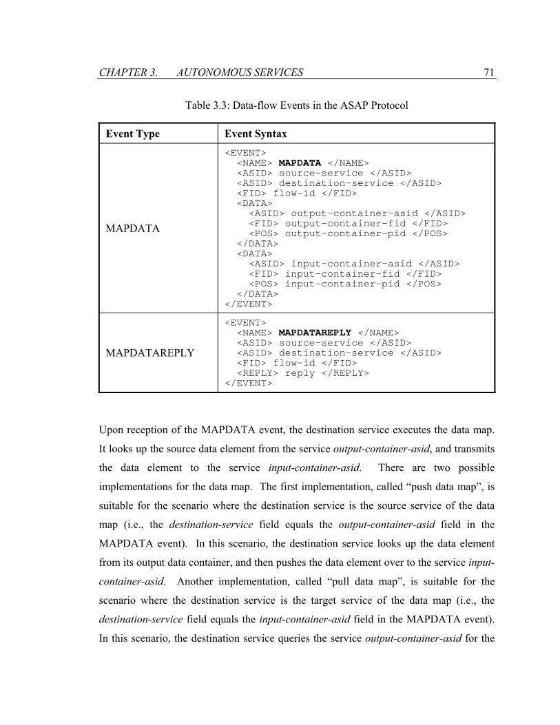
CHAPTER 3. AUTONOMOUS SERVICES 71
Table 3.3: Data-flow Events in the ASAP Protocol
Event Type Event Syntax
MAPDATA
<EVENT> <NAME> MAPDATA </NAME> <ASID> source-service </ASID> <ASID> destination-service </ASID> <FID> flow-id </FID> <DATA> <ASID> output-container-asid </ASID> <FID> output-container-fid </FID> <POS> output-container-pid </POS> </DATA> <DATA> <ASID> input-container-asid </ASID> <FID> input-container-fid </FID> <POS> input-container-pid </POS> </DATA> </EVENT>
MAPDATAREPLY
<EVENT> <NAME> MAPDATAREPLY </NAME> <ASID> source-service </ASID> <ASID> destination-service </ASID> <FID> flow-id </FID> <REPLY> reply </REPLY> </EVENT>
Upon reception of the MAPDATA event, the destination service executes the data map.
It looks up the source data element from the service output-container-asid, and transmits
the data element to the service input-container-asid. There are two possible
implementations for the data map. The first implementation, called “push data map”, is
suitable for the scenario where the destination service is the source service of the data
map (i.e., the destination-service field equals the output-container-asid field in the
MAPDATA event). In this scenario, the destination service looks up the data element
from its output data container, and then pushes the data element over to the service input-
container-asid. Another implementation, called “pull data map”, is suitable for the
scenario where the destination service is the target service of the data map (i.e., the
destination-service field equals the input-container-asid field in the MAPDATA event).
In this scenario, the destination service queries the service output-container-asid for the

CHAPTER 3. AUTONOMOUS SERVICES 72
source data element. The data element is fetched over to the destination service and
inserted into its input data container.
When the transmission of the data element is completed, a MAPDATAREPLY event is
sent by the destination service as the response to the MAPDATA event. The source-
service and destination-service fields of the MAPDATAREPLY event are swapped with
those in the MAPDATA event. The flow-id of the MAPDATAREPLY event is identical
to that of the MAPDATA event. The reply field contains the status information of the
data map request.
The MAPDATA event is the key event that enables the distribution of the data-flows. It
separates the control-flows from the data-flows of a megaservice. The autonomous
service that originates the MAPDATA event does not need to be the target service that
receives the data element. Instead, a service can use the MAPDATA event to coordinate
the data-flows between two other services. Using the MAPDATA event, the controller
for a megaservice can coordinate all the data-flows that are distributed among the
autonomous services. This enables the service composition infrastructure that has
centralized control-flows and distributed data-flows. The MAPDATA can also be used
to support a service composition infrastructure that has centralized data-flows. By
ensuring that all data maps involve the controller for the megaservice, the data-flows can
be centralized. This is achieved by tying the source-service field of the MAPDATA
event with either the output-container-asid field or the input-container-asid field. It
guarantees that the originator of the MAPDATA event is on either the sending end or the
receiving end of the data map request.
3.2.4 Auxiliary Events
The instantiation of a megaservice is supported by the CONTROLFILE event, as shown
in Table 3.4. No reply event to the CONTROLFILE event is needed.
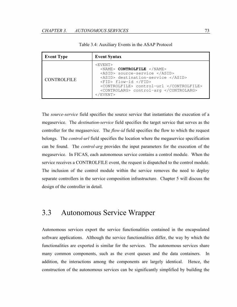
CHAPTER 3. AUTONOMOUS SERVICES 73
Table 3.4: Auxiliary Events in the ASAP Protocol
Event Type Event Syntax
CONTROLFILE
<EVENT> <NAME> CONTROLFILE </NAME> <ASID> source-service </ASID> <ASID> destination-service </ASID> <FID> flow-id </FID> <CONTROLFILE> control-url </CONTROLFILE> <CONTROLARG> control-arg </CONTROLARG> </EVENT>
The source-service field specifies the source service that instantiates the execution of a
megaservice. The destination-service field specifies the target service that serves as the
controller for the megaservice. The flow-id field specifies the flow to which the request
belongs. The control-url field specifies the location where the megaservice specification
can be found. The control-arg provides the input parameters for the execution of the
megaservice. In FICAS, each autonomous service contains a control module. When the
service receives a CONTROLFILE event, the request is dispatched to the control module.
The inclusion of the control module within the service removes the need to deploy
separate controllers in the service composition infrastructure. Chapter 5 will discuss the
design of the controller in detail.
3.3 Autonomous Service Wrapper
Autonomous services export the service functionalities contained in the encapsulated
software applications. Although the service functionalities differ, the way by which the
functionalities are exported is similar for the services. The autonomous services share
many common components, such as the event queues and the data containers. In
addition, the interactions among the components are largely identical. Hence, the
construction of the autonomous services can be significantly simplified by building the
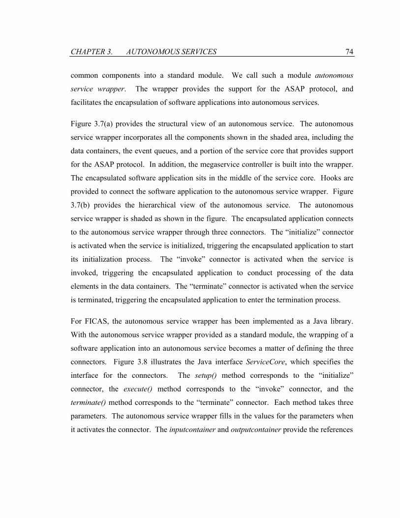
CHAPTER 3. AUTONOMOUS SERVICES 74
common components into a standard module. We call such a module autonomous
service wrapper. The wrapper provides the support for the ASAP protocol, and
facilitates the encapsulation of software applications into autonomous services.
Figure 3.7(a) provides the structural view of an autonomous service. The autonomous
service wrapper incorporates all the components shown in the shaded area, including the
data containers, the event queues, and a portion of the service core that provides support
for the ASAP protocol. In addition, the megaservice controller is built into the wrapper.
The encapsulated software application sits in the middle of the service core. Hooks are
provided to connect the software application to the autonomous service wrapper. Figure
3.7(b) provides the hierarchical view of the autonomous service. The autonomous
service wrapper is shaded as shown in the figure. The encapsulated application connects
to the autonomous service wrapper through three connectors. The “initialize” connector
is activated when the service is initialized, triggering the encapsulated application to start
its initialization process. The “invoke” connector is activated when the service is
invoked, triggering the encapsulated application to conduct processing of the data
elements in the data containers. The “terminate” connector is activated when the service
is terminated, triggering the encapsulated application to enter the termination process.
For FICAS, the autonomous service wrapper has been implemented as a Java library.
With the autonomous service wrapper provided as a standard module, the wrapping of a
software application into an autonomous service becomes a matter of defining the three
connectors. Figure 3.8 illustrates the Java interface ServiceCore, which specifies the
interface for the connectors. The setup() method corresponds to the “initialize”
connector, the execute() method corresponds to the “invoke” connector, and the
terminate() method corresponds to the “terminate” connector. Each method takes three
parameters. The autonomous service wrapper fills in the values for the parameters when
it activates the connector. The inputcontainer and outputcontainer provide the references

CHAPTER 3. AUTONOMOUS SERVICES 75
Input Data Container
Output Data Container
Input Event Queue
Output Event Q
ueue
Service Core(ASAP Support)
Megaservice C
ontroller
EncapsulatedSoftware
Application
AutonomousServiceWrapper
AutonomousServiceWrapper
initialize invoke terminate
EncapsulatedSoftware
Application
(a) Structural View (b) Hierarchical View
Figure 3.7: Autonomous Service Wrapper
to the data containers of the service, and the flowid identifies the flow to which the
service request belongs. Using the reference to the data containers and the flow identifier
of the request, the software application can look up the input parameters from the input
data container and produces the results into the output data container.
To build an autonomous service, an implementation of the ServiceCore interface is linked
to an autonomous service wrapper (ASW). Figure 3.9 shows a simple autonomous
service that adds up two input integers. The AdditionService class defines the service
core. No action is performed for the initialization and the termination of the service, as
specified by the setup() method and the terminate() method, respectively. The execute()
method specifies the actions for the invocation of the service. The two input numbers are
fetched from the input data container. Their values are added together, and the result is
put into the output data container. The autonomous service wrapper connects with the
service core by using the AdditionService class as an input of its constructor. The other
parameter of the constructor specifies the TCP/IP port of the autonomous service.
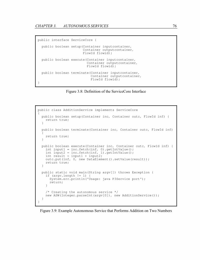
CHAPTER 3. AUTONOMOUS SERVICES 76
public interface ServiceCore public boolean setup(Container inputcontainer, Container outputcontainer, FlowId flowid); public boolean execute(Container inputcontainer, Container outputcontainer, FlowId flowid); public boolean terminate(Container inputcontainer, Container outputcontainer, FlowId flowid);
Figure 3.8: Definition of the ServiceCore Interface
public class AdditionService implements ServiceCore public boolean setup(Container inc, Container outc, FlowId inf) return true; public boolean terminate(Container inc, Container outc, FlowId inf) return true; public boolean execute(Container inc, Container outc, FlowId inf) int input1 = inc.fetch(inf, 0).getIntValue(); int input2 = inc.fetch(inf, 1).getIntValue(); int result = input1 + input2; outc.put(inf, 0, new DataElement().setValue(result)); return true; public static void main(String argv[]) throws Exception if (argv.length != 1) System.err.println("Usage: java P3Service port"); return; /* Creating the autonomous service */ new ASW(Integer.parseInt(argv[0]), new AdditionService());
Figure 3.9: Example Autonomous Service that Performs Addition on Two Numbers
CHAPTER 3. AUTONOMOUS SERVICES 77
3.4 Summary
This chapter reviews the modeling and the construction of autonomous services. The
FICAS metamodel is defined to describe the hierarchical composition of autonomous
services, the data model for exchanging information among the services, the internal
structure of the services, and the external interface for interacting with the services. The
metamodel allows the construction of homogeneous services in a heterogeneous
computing environment. Conceptually, every autonomous service consists a service
core, an input event queue, an output event queue, an input container and an output
container. Within the service, the data-flows are managed by the data containers, and the
control-flows are managed by the event queues. The key feature of the FICAS
metamodel is the separation of the data-flows from the control-flows. This separation
allows the autonomous services to be composed in a centralized control-flow and
distributed data-flow service composition infrastructure.
Based on the FICAS metamodel, the ASAP protocol defines the standard interface for
interacting with the autonomous services. The protocol specifies a set of events in XML,
as well as the expected responses by the autonomous services to the events. The protocol
breaks down a traditional service functional call into the initialization, the invocation, the
data management, and the termination phases. Each phase employs a set of its own
events. The division allows the different phases to be executed asynchronously and in
parallel. Furthermore, the ASAP protocol supports the distribution of data-flows through
the data management event, i.e., the MAPDATA event. Using the MAPDATA event, a
controller can coordinate the autonomous services centrally while at the same time
distributes the data-flows among the services.
The construction of an autonomous service is supported by the autonomous service
wrapper. The wrapper incorporates the common components of the service, such as the
data containers, the event queues, a portion of the service core, the support for the ASAP
protocol, and the megaservice controller. A software application can be attached to the
CHAPTER 3. AUTONOMOUS SERVICES 78
wrapper via three connectors, which specify the tasks to be performed by the application
for the initialization, the termination and the invocation of the autonomous service. An
example is used to demonstrate the process of constructing an autonomous service. The
autonomous service wrapper is provided as a Java class, and the connectors are provided
as three functions in a Java interface. Wrapping a software application into an
autonomous service becomes a matter of implementing the three functions for
initialization, invocation and termination of the service. The simple process of
constructing autonomous services will greatly facilitate the integration of more legacy
software applications.

Chapter 4
Buildtime Environment of FICAS
A megaprogrammer conducts the composition of autonomous services by defining a
formal specification, which specifies and brings together the functionalities provided by
the autonomous services as an integrated entity. The specification describes which
autonomous services are involved in the megaservice, when the autonomous services are
invoked, how the autonomous services interact with each other, and what other
functionalities are required by the megaservice in addition to those provided by the
autonomous services. The specification is also known by myriad names such as
megaprogram [14], ensemble [79], composition [74], grid program [10], and workflow
[53].
FICAS consists a buildtime environment for specifying the composition of the
megaservice, and a runtime environment for executing the composition. The buildtime
environment provides the framework and the tools to describe the composition of
autonomous services, to check the validity of the composition, and to compile the
composition into an executable sequence. The executable sequence serves as the
interface between the buildtime and the runtime environments.
CHAPTER 4. FICAS BUILDTIME ENVIRONMENT 80
The buildtime environment of FICAS consists of three layers: the source layer, the
compilation layer, and the executable layer, as shown in Figure 4.1. The source layer
provides the tools for specifying the megaservice. The compilation layer is responsible
for validating the source programs and converting the programs into executables. The
executable layer hosts the actual executables and serves as the interface to the runtime
environment of FICAS. Each layer consists of a compositional specification and a
computational specification of the megaservice. The compositional specification
describes the interrelationships of the autonomous services involved in the megaservice,
and the computational specification describes the processing of the data obtained from
the autonomous services.
For compositional specification, a purely compositional language CLAS is defined to
facilitate a high-level abstraction for describing functionalities of a megaservice.
Utilizing a high-level compositional language allows the specification be independent of
any knowledge of the heterogeneous distributed systems, the client-server environment,
and the computational programs. The CLAS compiler takes a CLAS program as input,
validates its content, and convert it into a control sequence. The control sequence serves
as the executable to be carried out by the runtime environment. The use of the control
sequence provides flexibility to the composition of the megaservice. Other languages
and tools may be used in FICAS to specify the composition, as long as the control
sequence is generated as the result.
The mobile class complements the CLAS language by providing a clean and powerful
mechanism to specify computational functionalities. The computational specification and
the compositional specification of a megaservice are tied together through the mobile
class construct in the CLAS language. Using the construct, a CLAS program can invoke
a mobile class to process data obtained from the autonomous services. The CLAS
program can also use the data generated by the mobile class the same way as the data
generated by the autonomous services. The source code for the mobile class is specified
in Java [7]. As a general programming language, Java offers a wide range of

CHAPTER 4. FICAS BUILDTIME ENVIRONMENT 81
computational constructs. A commercially available Java compiler is utilized to compile
the source code into a Java class file that contains the Java byte codes, which are
dynamically loaded by the runtime environment when the mobile class is invoked.
Besides the basic requirements of a buildtime environment, such as the ease of use of the
tools, the expressive power of the languages, etc., we also take into consideration various
features for the performance optimization of the megaservices, particularly through the
distribution of data-flows. The rest of this chapter will describe the buildtime
environment in detail.
Executable
CompilationCLAS
Compiler
FICASControl
Sequences
JavaCompiler
CLASPrograms
MobileClass
SourceCodes
MobileClasses
Source
CompositionalSpecification
ComputationalSpecification
Figure 4.1: Architecture of the Buildtime Environment of FICAS
CHAPTER 4. FICAS BUILDTIME ENVIRONMENT 82
4.1 Compositional Specification
The Compositional Language for Autonomous Services (CLAS) is a practical general
purpose language for composing megaservices using autonomous services. The CLAS
language provides the necessary high-level abstractions to describe the behavior of the
megaservices. It is built around concepts and abstractions that do not correspond directly
to the features of the underlying machine, therefore hides the heterogeneity of the
computing systems. A compiler is used to compile a CLAS program into a control
sequence that can be executed by the runtime environment. The control sequence
provides the separation between the specification and the execution of the megaservice.
The CLAS language is designed to be a purely compositional language, which concerns
with the act of combining parts and elements of a task into a whole. It aims to alleviate
the megaprogrammers the responsibility of explicitly managing autonomous services, so
the megaprogrammers can focus on the composition of service functionalities. In
addition, the CLAS language is designed with performance in mind. It is designed to be
a simple yet powerful language that supports compile-time as well as run-time
optimization.
4.1.1 Data Types and Operations
The CLAS language uses a weak data type system. No type checking is performed at the
compile time. Types are checked during the runtime, and exceptions may be raised if
type conflicts are detected. There are five data types in CLAS: BLOB, Boolean, Integer,
Real and String. The first type, BLOB, is used exclusively for representing data
transferred among autonomous services. The BLOB data remains opaque to the CLAS
programs. A megaservice does not interpret or modify the BLOB data generated by the
autonomous services. No data operations are designed in the CLAS language for the
BLOB data, which is used solely for establishing data-flows among the autonomous
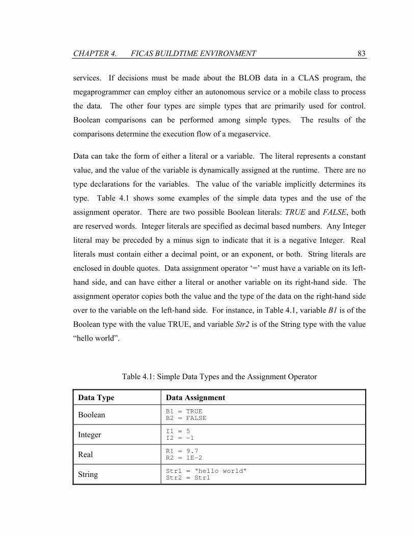
CHAPTER 4. FICAS BUILDTIME ENVIRONMENT 83
services. If decisions must be made about the BLOB data in a CLAS program, the
megaprogrammer can employ either an autonomous service or a mobile class to process
the data. The other four types are simple types that are primarily used for control.
Boolean comparisons can be performed among simple types. The results of the
comparisons determine the execution flow of a megaservice.
Data can take the form of either a literal or a variable. The literal represents a constant
value, and the value of the variable is dynamically assigned at the runtime. There are no
type declarations for the variables. The value of the variable implicitly determines its
type. Table 4.1 shows some examples of the simple data types and the use of the
assignment operator. There are two possible Boolean literals: TRUE and FALSE, both
are reserved words. Integer literals are specified as decimal based numbers. Any Integer
literal may be preceded by a minus sign to indicate that it is a negative Integer. Real
literals must contain either a decimal point, or an exponent, or both. String literals are
enclosed in double quotes. Data assignment operator ‘=’ must have a variable on its left-
hand side, and can have either a literal or another variable on its right-hand side. The
assignment operator copies both the value and the type of the data on the right-hand side
over to the variable on the left-hand side. For instance, in Table 4.1, variable B1 is of the
Boolean type with the value TRUE, and variable Str2 is of the String type with the value
“hello world”.
Table 4.1: Simple Data Types and the Assignment Operator
Data Type Data Assignment
Boolean B1 = TRUE B2 = FALSE
Integer I1 = 5 I2 = -1
Real R1 = 9.7 R2 = 1E-2
String Str1 = “hello world” Str2 = Str1

CHAPTER 4. FICAS BUILDTIME ENVIRONMENT 84
The primary use of the simple types is for boolean expressions. A boolean expression
returns the value of either TRUE or FALSE. The simplest boolean expression is a single
boolean literal or variable. More complex boolean expressions take the form of a
boolean comparison. Table 4.2 lists the boolean comparison operators. Two data of the
simple types can be compared using the boolean comparison operators. While most of
the types are supported for all the boolean comparison operators, some are not.
Unsupported boolean comparisons will raise exceptions at the runtime. For instance, the
‘>’ comparison between two Boolean values is not permitted.
When the data on both sides of the comparison operator do not have the same type, type
conversions are implicitly performed at the runtime. Both data are converted into a
common type before their values are compared. Table 4.3 shows the expected type
conversions when a left-hand side value is compared against a right-hand side value. For
instance, when an Integer value is compared against a Real value, the Integer value is
implicitly converted into the Real type; when a String value is compared against an
Integer value, the String value is implicitly converted into the Integer type. If no valid
type conversion is found between the two values, runtime exceptions are raised. For
instance, it is illegal to compare an Integer value with a Boolean value.
Table 4.2: Operators for Boolean Comparison
Data Type Sign Name
Boolean Integer Real String
== Equal To
> Greater Than
< Less Than
!= Not Equal To
>= Greater Than or Equal To
<= Less Than or Equal To

CHAPTER 4. FICAS BUILDTIME ENVIRONMENT 85
Table 4.3: Data Type Conversions for Boolean Comparison
Right-hand SideValue
Left-hand Side Value
Boolean Integer Real String
Boolean Boolean
Integer Integer Real Integer
Real Real Real Real
String Integer Real String
Boolean expressions can further compose of complex boolean expressions with the
“NOT”, “AND”, and “OR” operators:
• ! (expression): The NOT operator negates the value of the expression. The operator
returns TRUE if the expression is FALSE, and returns FALSE otherwise.
• && (expression1, expression2): The AND operator returns TRUE if both expressions
are TRUE, and returns FALSE otherwise. There is no predetermined order for the
evaluation of the sub expressions. The design is different from many other
programming languages (e.g., C/C++ [84]) that assume expressions are evaluated
from left to right. By assuming no particular order of evaluation, we can improve the
performance of evaluating the boolean expression by conducting evaluation of the
expressions in parallel.
• || (expression1, expression2): The OR operator returns TRUE if either expression is
TRUE, and returns FALSE otherwise. The evaluation of the expressions is conducted
in the same fashion as that in an AND clause.
CHAPTER 4. FICAS BUILDTIME ENVIRONMENT 86
4.1.2 Autonomous Service Statement
Traditionally, a remote procedural call is used to invoke an autonomous service [12].
The call usually consists of invoking a method and getting its results back in a
synchronous way. The calling client waits during the procedure call, and the overall
structure of the client program remains simple. In contrast, an asynchronous call avoids
any waits for the client but makes the client program more complex. The client program
needs to manage replies to the asynchronous call in a multithreaded fashion.
The CLAS language combines the advantages of both the synchronous and the
asynchronous procedure calls. It intends to harness the potential parallelism within a
megaservice, while at the same time keeps the megaservice program sequential and
simple. The procedural call to an autonomous service is split into four statements:
SETUP, INVOKE, EXTRACT and TERMINATE. While each statement is synchronous
in nature, the call to the autonomous service is carried out asynchronously. The result is
that the megaservice is specified in a sequential and synchronous fashion, and the runtime
optimizes the megaservice performance by conducting scheduling of the asynchronous
statements.
• Autonomous Service Setup
ServiceHandle = SETUP(“Sample Service”)
The SETUP statement is used to establish communication with an autonomous service
referred by its autonomous service name. The statement takes the autonomous service
name as the input and returns a handle to the autonomous service. The SETUP statement
serves two purposes. First, it requests the autonomous service to perform initialization
for the future invocation requests. The statement triggers the “initialize” connector of the
autonomous service and invokes the setup() method in the service core. Second, the
statement establishes a service handle that contains the parameters necessary for
subsequent interactions with the autonomous service.
CHAPTER 4. FICAS BUILDTIME ENVIRONMENT 87
The autonomous service name is specified in the form of an ASCII string. To hide
implementation details from the language, the autonomous service name used by the
megaservice specification is dynamically mapped to the information needed by the
runtime environment. For instance, “Sample Service” may be the autonomous service
name that a megaprogrammer wishes to use. It is mapped in runtime to such information
as the IP address and the TCP/IP port number of the autonomous service. Chapter 5 will
discuss how the autonomous service directory is used to conduct the mapping in more
detail.
• Autonomous Service Invocation
InvocationHandle = ServiceHandle.INVOKE(param1, param2, …)
The INVOKE statement starts the invocation of an autonomous service referred by the
handle returned from the SETUP statement. Syntactically, the INVOKE statement is
regarded as a method call on the service handle. The INVOKE statement triggers the
“invoke” connector of the autonomous service and invokes the execute() method in the
service core. The input data elements for the service invocation are provided as the
parameters to the INVOKE statement. The parameters are referred by position starting
from 0. The position index for param1 is 0, and the position index for param2 is 1, and
so on. The INVOKE statement returns an invocation handle, which can be used for
further interactions with the invocation instance. For instance, results can be extracted
from the invocation using the invocation handle.
• Autonomous Service Extraction
Variable = InvocationHandle.EXTRACT()
The EXTRACT statement collects the results of an autonomous service invocation
referred by the invocation handle returned from the INVOKE statement. The EXTRACT
statement establishes the data dependencies among the autonomous services. When the
variable extracted from one autonomous service is used as the input to another
CHAPTER 4. FICAS BUILDTIME ENVIRONMENT 88
autonomous service, a data map is formed between the two autonomous services, and
they are data dependent on each other.
• Autonomous Service Termination
ServiceHandle.TERMINATE()
The TERMINATE statement ends the connection to a specific autonomous service.
Garbage collection on the autonomous service is conducted for the megaservice as the
result of the TERMINATE statement. Terminating the connection to the autonomous
service only affects the megaservice that initiates the TERMINATE statement. Other
megaservices accessing the same autonomous service are unaffected.
4.1.3 Conditional Statements
The CLAS language has a very limited set of control statements, with little regard for
providing functionality beyond composition. Conditional execution in a megaservice is
achieved through the IF-THEN-ELSE and the WHILE statements, used in combination
with the boolean expressions. When the conditional statements are used, the behavior of
the megaservice is dynamically determined at runtime based on the value of the boolean
expressions.
• Branch Statement
IF (expression) THEN Statement_List [ ELSE Statement_List ]
The branch statement is a control mechanism used for making dynamic branching
decisions based on the value of a boolean expression. The keyword IF is followed by a
set of parentheses containing the boolean expression to be tested. If the expression
evaluates to be TRUE, the list of statements contained in the THEN clause is executed.
The ELSE clause is optional. When the ELSE clause is present, it is executed if the
boolean expression evaluates to be FALSE.
CHAPTER 4. FICAS BUILDTIME ENVIRONMENT 89
• While Loop Statement
WHILE (expression) Statement_List
The while loop statement is a control mechanism that provides looping operations. The
boolean expression enclosed in parentheses is evaluated. If the result is TRUE, then the
body of the loop (i.e. the list of statements enclosed in braces) is executed. Then the
boolean expression is evaluated again. And if it is TRUE again, the list of statements is
executed once more. This process continues until the boolean expression becomes
FALSE.
4.1.4 Comparison Between CLAS and CLAM
The CLAS language is derived from the CLAM language [80], the compositional
language used in the CHAIMS (Compiling High-level Access Interfaces for Multi-site
Software) project. The objective of CHAIMS is to investigate the compositional
programming paradigm, which represents a high level of abstraction in programming [9,
92]. The CLAM language enables programmers to use megamodules, a similar concept
to the autonomous services, to conduct service composition. The CLAM language serves
as a point of departure for the CLAS language. They share many similarities:
• The CLAS language uses the same invocation model as the CLAM language. The
autonomous services are composed using the Ideal Worker Ideal Manager (IWIM)
model [6, 68]. The IWIM model can be viewed as a contractual relationship, where a
general contractor hires subcontractors to perform certain jobs. The CLAS language
treats autonomous services as entities with exposed methods, and a megaservice
selects appropriate autonomous services to carry out the sub-tasks. The megaservice
is the general contractor, and the autonomous services are the subcontractors.
• Similar to the CLAM language, the CLAS language decomposes a CALL statement
into multiple phases. In traditional programming languages, the CALL statement

CHAPTER 4. FICAS BUILDTIME ENVIRONMENT 90
typically assumes synchrony in execution [12], forcing possible parallel tasks into
sequential execution order. By breaking up the CALL statement into several
primitives, we obtain the asynchronicity necessary to support parallel invocation of
the remote methods from a sequential client. The achieved parallelism is intrinsically
important to the compositional programming paradigm because the autonomous
megamodules are in general long running and resource intensive. The split of the
CALL statement allows runtime optimizations to be performed [74, 96].
• Both languages are purely compositional. By ridding all computational constructs
from the language, we intend to free the megaprogrammers from computational
programming. There are a small number of control constructs. The structure of both
languages reflects the simple elegance achievable when composition is the only goal.
• Both languages assume heterogeneous computing environments, and no limitation on
the runtime systems is implied. Although FICAS is designed to support data-flow
distribution, the CLAS language is data-flow agnostic. It supports both centralized
and distributed data-flow runtime environments. Data communications among
autonomous services are not explicitly specified. Rather, the data-flows are derived
from implicit data dependencies among the autonomous services.
Despite the similarities, the two languages differ in many aspects:
• The invocation and result passing schemes of the CLAM language are simplified.
The primitives for manipulating parameters of a service invocation are built into the
invocation primitive. For CLAS, parameters are always passed along with the service
invocation. In addition, CLAS combines the primitives for result extraction and
status examination of a service invocation. A single primitive EXTRACT is used to
query information from the service.
• The CLAS language allows megaservices to take input parameters. A special
reserved keyword “%%” is introduced to represent the input parameter. Although it

CHAPTER 4. FICAS BUILDTIME ENVIRONMENT 91
is a simple improvement over CLAM, the ability for megaservices to take input
parameters is a big step toward a multi-tiered service composition infrastructure,
where megaservices can be further composed.
• The CLAS language improves on the CLAM language in its ability to handle
computations. Being a purely compositional language, the CLAM language offers no
practical alternatives when some computations are desired. Even complex
comparisons in a megaservice require special autonomous services to be built. It is
inefficient to employ the autonomous services, since they in general involve a lot of
overhead. More importantly, there is a conflict in role and in expertise for
megaprogrammers to serve as the owner of the autonomous services, which should be
maintained independent of the megaservice. FICAS addresses these issues by
utilizing mobile classes to perform computations. The way of invoking a mobile
class is very similar to that of invoking an autonomous service, hence preserving the
elegance and simplicity of the language. In terms of ownership and maintenance, the
mobile classes are considered attachments to the CLAS programs. The
megaprogrammer creates, owns and maintains the CLAS programs, as well as the
associated mobile classes.
4.2 CLAS Compiler and FICAS Control Sequence
A megaservice program written in the CLAS language is compiled into a control
sequence. The CLAS compiler is built using the JavaCC compiler compiler [89], which
conceptually consists of three phases:
• Lexical analysis – The input symbols are scanned and grouped into meaningful units
called tokens. During the lexical analysis phase, literals are distinguished from
variables. Exceptions are raised for illegal combinations of letters and digits.
CHAPTER 4. FICAS BUILDTIME ENVIRONMENT 92
• Syntax analysis – The tokens generated by the lexical analysis are grouped into
syntactic units as statements. During the process, a parse tree is generated to
represent the syntactic structure of the program. If a program does not meet the
syntactic requirements as a well-formed program, then the parsing phase produces an
error.
• Code generation – The parse tree generated by the syntax analysis is mapped into a
control sequence.
4.2.1 Lexical Analysis
Table 4.4 lists the legal tokens in the CLAS language. Tokens are categorized as
comments, separators, variables, literals, keywords, and operators:
• A comment can be placed anywhere that white spaces (i.e., blanks and tabs) can
appear, except within a string literal. A comment consists of any text delimited by /*
and */, and may occupy more than one line. It can also consists of any text led by //
on a single line. Comments cannot be nested.
• Separators are used to establish relative position of tokens within a CLAS program.
• Variables are names for entities in a CLAS program. They are composed of only
letters, digits and underscores, and they cannot start with a digit. In addition,
variables cannot be any of the reserved words.
• Literals are the constants used in a CLAS program. There are only two Boolean
literals: TRUE and FALSE, both reserved words. An Integer literal consists of one or
more digits. It may be preceded by a minus sign to represent a negative number. A
Real literal consists of a series of digits representing the whole part of the number,
followed by a decimal point, and a series of digits representing the fractional part. A
Real literal can also be represented in scientific notation, consisting of a mantissa in

CHAPTER 4. FICAS BUILDTIME ENVIRONMENT 93
decimal notation, followed by the letter E, and an exponent. A String literal consists
of double quotation marks containing any number of characters. The %% is
considered a special String literal that represents the input parameter to the CLAS
program.
• Keywords are constructs reserved by the CLAS compiler for the autonomous service
statements, the conditional statements, and the mobile class statement.
• Operators are used for the assignment of values and for creating boolean expressions.
Table 4.4: Tokens in the CLAS Language
Token Type Token Values or Examples
Comment /* this is a comment */
Separator ( ) , .
Variable ABC abc a0 a_ _a
Boolean Literal TRUE FALSE
Integer Literal 0 1 -2
Real Literal 1.2 -2.1 1E-2 -1E2 Lite
ral
String Literal “” “hello world” %%
Service Invocation SETUP INVOKE EXTRACT TERMINATE
While Loop WHILE
Branch IF THEN ELSE
Key
wor
d
Mobile Class Invocation MCLASS
Assignment =
Comparison < > <= => == !=
Ope
rato
r
Boolean Composition ! && ||
CHAPTER 4. FICAS BUILDTIME ENVIRONMENT 94
4.2.2 Syntax Analysis
The BNF grammar [57, 62] for the CLAS language is shown in Table 4.5. Production
rules are formed by interpreting the non-terminal symbols on the left-hand side as the
sequences of symbols on the right-hand side. String literals are single quoted. Optional
items are enclosed in brackets and are separated by ‘|’. Repetitive items that may appear
zero or more times are enclosed in parentheses followed by a ‘*’. If an item is enclosed
by a pair of parentheses followed by a ‘?’, it may appear at most once.
A CLAS program starts with a programname, followed by an optional baseclasspath, and
a sequential list of statements. The programname is a variable that annotates the name of
the megaservice. The baseclasspath is a String literal that represents the default search
path for the mobile class repository. The baseclasspath is used in combination with the
MclassStatement for the invocation of mobile classes.
There are three types of statements in CLAS: branch statement, while loop, or simple
statement. Both branch statement and while loop are composite statements that include a
boolean expression for the conditional test and an execution body that consists of one or
two lists of statements. A branch statement starts with the keyword “IF”, and a while
loop statement starts with the keyword “WHILE”. The syntax for the branch statement
and the while loop were discussed earlier in Section 4.1.3.
There are six types of simple statements. The assignment statement was discussed in
Section 4.1.1, and the four autonomous service statements (i.e., SETUP, INVOKE,
EXTRACT and TERMINATE) were discussed in Section 4.1.2. The BNF production
rules provide the formal specifications for them. The servicehandle, invocationhandle,
and var are variables. The servicename is a String literal. The argument can be either a
variable or a literal. The definition for the mobile class statement is also provided, and
details about the mobile classes will be discussed in Section 4.3.
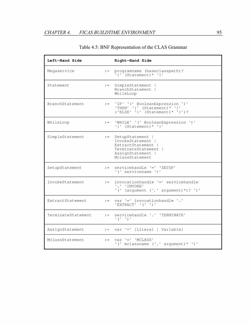
CHAPTER 4. FICAS BUILDTIME ENVIRONMENT 95
Table 4.5: BNF Representation of the CLAS Grammar
Left-Hand Side Right-Hand Side
Megaservice := programname (baseclasspath)? ‘’ (Statement)* ‘’
Statement := SimpleStatement | BranchStatement | WhileLoop
BranchStatement := ‘IF’ ‘(’ BooleanExpression ‘)’ ‘THEN’ ‘’ (Statement)* ‘’ (‘ELSE’ ‘’ (Statement)* ‘’)?
WhileLoop := ‘WHILE’ ‘(’ BooleanExpression ‘)’ ‘’ (Statement)* ‘’
SimpleStatement := SetupStatement | InvokeStatement | ExtractStatement | TerminateStatement | AssignStatement | MclassStatement
SetupStatement := servicehandle ‘=’ ‘SETUP’ ‘(’ servicename ‘)’
InvokeStatement := invocationhandle ‘=’ servicehandle ‘.’ ‘INVOKE’ ‘(’ (argument (‘,’ argument)*)? ‘)’
ExtractStatement := var ‘=’ invocationhandle ‘.’ ‘EXTRACT’ ‘(’ ‘)’
TerminateStatement := servicehandle ‘.’ ‘TERMINATE’ ‘(’ ‘)’
AssignStatement := var ‘=’ [Literal | Variable]
MclassStatement := var ‘=’ ‘MCLASS’ ‘(’ mclassname (‘,’ argument)* ‘)’
CHAPTER 4. FICAS BUILDTIME ENVIRONMENT 96
4.2.3 Code Generation
The final phase of the CLAS compiler is code generation. The parse tree formed by the
syntax analysis is used to generate the control sequence that serves as the input to the
runtime environment of FICAS. The control sequence is encoded in XML, which is
chosen for two reasons. First, XML presents a homogeneous data layer for the
heterogeneous runtime environment. Any megaservice controller will be able to read and
interpret the content of the control sequence. Second, XML provides a simple
mechanism to describe the hierarchical structure of the CLAS program. The parse tree
naturally maps to an XML document. Each statement in the CLAS program can be
represented as an XML tree, in which the child elements describe the components of the
statement.
Table 4.6 shows the definition of the elements for the FICAS control sequence. The root
element of the control sequence has the tag FICAS. The first two child elements of the
root element are the PROGRAMNAME element and the BASECP element. The
PROGRAMNAME element contains the programname field from the parse tree,
representing the name of the megaservice. The BASECP element is optional. When
used, it contains the baseclasspath field whose value represents the base URL for the
mobile class repository.
For each statement in the CLAS program, a corresponding FICAS control element is
generated. Each control element further consists of child elements that describe the
components of a statement.
• Branch Statement: The root element of a branch statement is tagged BRANCH. The
element has three child elements: a BOOLEAN element, a THEN element, and an
optional ELSE element. The BOOLEAN element is the root of a boolean expression
parse tree, whose value determines the execution flow of the branch statement. The
THEN element contains the statement group that is executed if the boolean expression
is evaluated to be TRUE. The ELSE element contains the statement group that is

CHAPTER 4. FICAS BUILDTIME ENVIRONMENT 97
executed if the boolean expression is evaluated to be FALSE. A statement group is a
list of control elements, each representing a statement.
• While Loop Statement: The root element of a while loop statement is tagged
WHILELOOP. The element has two child elements: a BOOLEAN element and a
WHILEBODY element. The BOOLEAN element is the root of a boolean expression
parse tree, whose value is to be evaluated once for every execution of the loop body.
The WHILEBODY element contains a statement group, which consists of a list of
elements corresponding to the statements in the loop body.
• Autonomous Service Setup Statement: The root element of an autonomous service
setup statement is tagged SETUP. The element has two child elements: a
SERVICEHANDLE element and a SERVICENAME element. The SERVICENAME
element contains the name of the autonomous service to be initialized. The
SERVICEHANDLE element refers to the handle of the initialized service.
• Autonomous Service Invocation Statement: The root element of an autonomous
service invocation statement is tagged INVOKE. The element has three child
elements: an INVOCATIONHANDLE element, a SERVICEHANDLE element, and an
optional VALUELIST element. The SERVICEHANDLE element refers to the handle
of the autonomous services to be invoked. The VALUELIST element contains a list of
elements that correspond to the input parameters for the service invocation. The
INVOCATIONHANDLE element refers to the handle of the returned invocation
instance.
• Autonomous Service Extraction Statement: The root element of an autonomous
service extraction statement is tagged EXTRACT. The element has two child
elements: a VARIABLE element and an INVOCATIONHANDLE element. The
INVOCATIONHANDLE element refers to the specific service invocation instance
from which the output data is queried. The VARIABLE element contains the variable
to which the result should be assigned.

CHAPTER 4. FICAS BUILDTIME ENVIRONMENT 98
• Autonomous Service Termination Statement: The root element of an autonomous
service termination statement is tagged TERMINATE. The element has a single child
element: a SERVICEHANDLE element. The SERVICEHANDLE element refers to the
handle of the autonomous service to be terminated.
• Assignment Statement: The root element of an assignment statement is tagged
ASSIGNMENT. The element has two child elements that refer to the two sides of an
assignment. The first element, referring to the left-hand-side of the assignment,
contains a variable to which the value of the right-hand-side of the assignment will be
assigned. The second element, referring to the right-hand-side of the statement,
contains either a literal or a variable.
• Mobile Class Statement: The root element of a mobile class statement is tagged
MCLASS. The element has three child elements: a VARIABLE element, a
MCLASSNAME element, and an optional VALUELIST element. The MCLASS
element contains the name of the mobile class to be invoked. The VALUELIST
element contains a list of elements that correspond to the input parameters of the
mobile class. The VARIABLE element contains the variable to which the result of the
mobile class invocation should be assigned.

CHAPTER 4. FICAS BUILDTIME ENVIRONMENT 99
Table 4.6: Definitions of the FICAS Control Elements
Element Contains
FICAS PROGRAMNAME, BASECP?, (WHILE | BRANCH | SETUP | INVOKE | EXTRACT | TERMINATE | ASSIGNMENT | MCLASS)*
BRANCH BOOLEAN, THEN, ELSE?
THEN (WHILE | BRANCH | SETUP | INVOKE | EXTRACT | TERMINATE | ASSIGNMENT | MCLASS)*
ELSE (WHILE | BRANCH | SETUP | INVOKE | EXTRACT | TERMINATE | ASSIGNMENT | MCLASS)*
WHILE BOOLEAN, WHILEBODY
WHILEBODY (WHILE | BRANCH | SETUP | INVOKE | EXTRACT | TERMINATE | ASSIGNMENT | MCLASS)*
SETUP SERVICEHANDLE, SERVICENAME
INVOKE INVOCATIONHANDLE, SERVICEHANDLE, VALUELIST
EXTRACT VARIABLE, INVOCATIONHANDLE
TERMINATE SERVICEHANDLE
ASSIGNMENT VARIABLE, (VARIABLE | BOOLEANLITERAL | REALLITERAL | INTEGERLITERAL | STRINGLITERAL)
MCLASS VARIABLE, MCLASSNAME, VALUELIST
VALUELIST (VARIABLE | BOOLEANLITERAL | REALLITERAL | INTEGERLITERAL | STRINGLITERAL)*
BOOLEAN (BOP, BOOLEAN, BOOLEAN?) | (VARIABLE | BOOLEANLITERAL | REALLITERAL | INTEGERLITERAL | STRINGLITERAL), COMPARESIGN, (VARIABLE | BOOLEANLITERAL | REALLITERAL | INTEGERLITERAL | STRINGLITERAL)
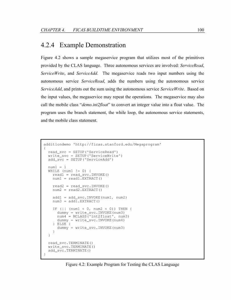
CHAPTER 4. FICAS BUILDTIME ENVIRONMENT 100
4.2.4 Example Demonstration
Figure 4.2 shows a sample megaservice program that utilizes most of the primitives
provided by the CLAS language. Three autonomous services are involved: ServiceRead,
ServiceWrite, and ServiceAdd. The megaservice reads two input numbers using the
autonomous service ServiceRead, adds the numbers using the autonomous service
ServiceAdd, and prints out the sum using the autonomous service ServiceWrite. Based on
the input values, the megaservice may repeat the operations. The megaservice may also
call the mobile class “demo.int2float” to convert an integer value into a float value. The
program uses the branch statement, the while loop, the autonomous service statements,
and the mobile class statement.
additiondemo "http://ficas.stanford.edu/Megaprogram" read_svc = SETUP("ServiceRead") write_svc = SETUP("ServiceWrite") add_svc = SETUP("ServiceAdd") num1 = 1 WHILE (num1 != 0) read1 = read_svc.INVOKE() num1 = read1.EXTRACT() read2 = read_svc.INVOKE() num2 = read2.EXTRACT() add1 = add_svc.INVOKE(num1, num2) num3 = add1.EXTRACT() IF (|| (num1 < 0, num2 < 0)) THEN dummy = write_svc.INVOKE(num3) num4 = MCLASS("int2float", num3) dummy = write_svc.INVOKE(num4) ELSE dummy = write_svc.INVOKE(num3) read_svc.TERMINATE() write_svc.TERMINATE() add_svc.TERMINATE()
Figure 4.2: Example Program for Testing the CLAS Language
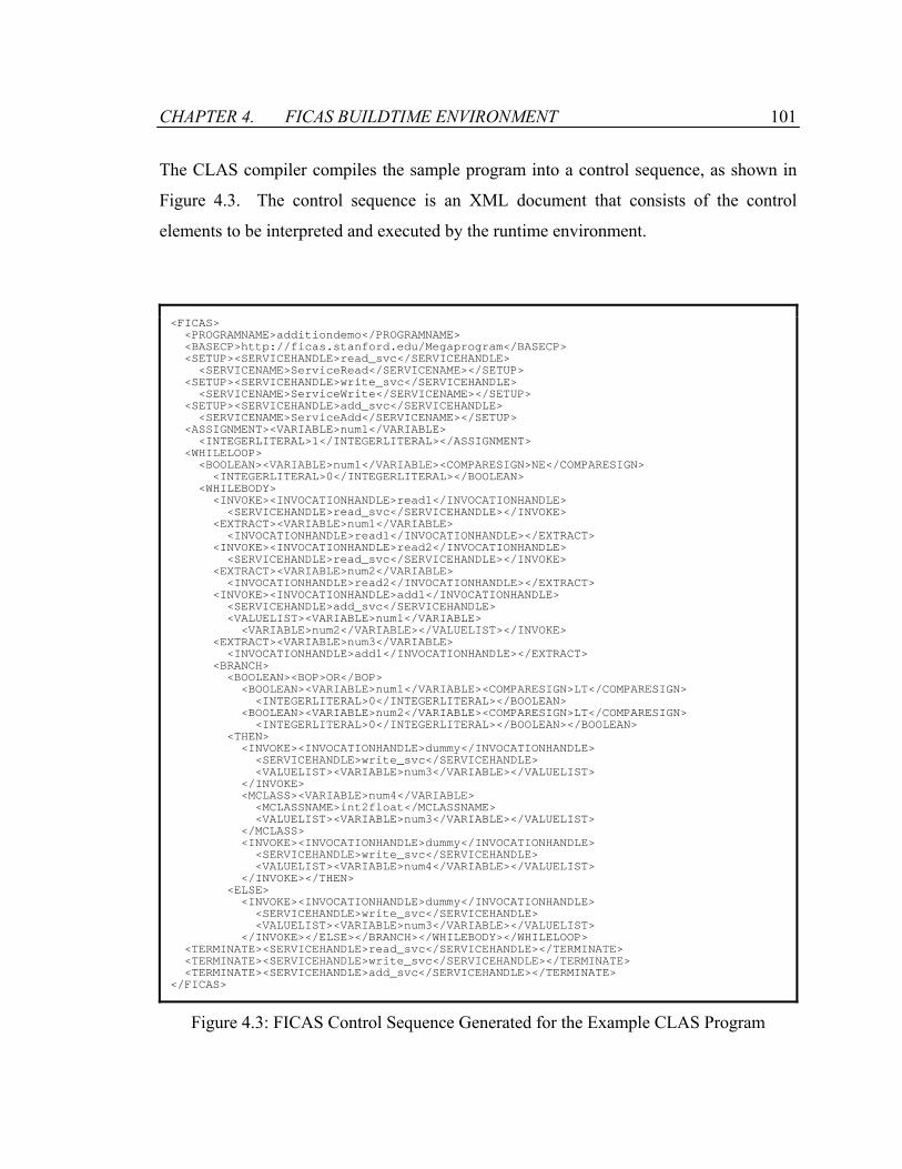
CHAPTER 4. FICAS BUILDTIME ENVIRONMENT 101
The CLAS compiler compiles the sample program into a control sequence, as shown in
Figure 4.3. The control sequence is an XML document that consists of the control
elements to be interpreted and executed by the runtime environment.
<FICAS> <PROGRAMNAME>additiondemo</PROGRAMNAME> <BASECP>http://ficas.stanford.edu/Megaprogram</BASECP> <SETUP><SERVICEHANDLE>read_svc</SERVICEHANDLE> <SERVICENAME>ServiceRead</SERVICENAME></SETUP> <SETUP><SERVICEHANDLE>write_svc</SERVICEHANDLE> <SERVICENAME>ServiceWrite</SERVICENAME></SETUP> <SETUP><SERVICEHANDLE>add_svc</SERVICEHANDLE> <SERVICENAME>ServiceAdd</SERVICENAME></SETUP> <ASSIGNMENT><VARIABLE>num1</VARIABLE> <INTEGERLITERAL>1</INTEGERLITERAL></ASSIGNMENT> <WHILELOOP> <BOOLEAN><VARIABLE>num1</VARIABLE><COMPARESIGN>NE</COMPARESIGN> <INTEGERLITERAL>0</INTEGERLITERAL></BOOLEAN> <WHILEBODY> <INVOKE><INVOCATIONHANDLE>read1</INVOCATIONHANDLE> <SERVICEHANDLE>read_svc</SERVICEHANDLE></INVOKE> <EXTRACT><VARIABLE>num1</VARIABLE> <INVOCATIONHANDLE>read1</INVOCATIONHANDLE></EXTRACT> <INVOKE><INVOCATIONHANDLE>read2</INVOCATIONHANDLE> <SERVICEHANDLE>read_svc</SERVICEHANDLE></INVOKE> <EXTRACT><VARIABLE>num2</VARIABLE> <INVOCATIONHANDLE>read2</INVOCATIONHANDLE></EXTRACT> <INVOKE><INVOCATIONHANDLE>add1</INVOCATIONHANDLE> <SERVICEHANDLE>add_svc</SERVICEHANDLE> <VALUELIST><VARIABLE>num1</VARIABLE> <VARIABLE>num2</VARIABLE></VALUELIST></INVOKE> <EXTRACT><VARIABLE>num3</VARIABLE> <INVOCATIONHANDLE>add1</INVOCATIONHANDLE></EXTRACT> <BRANCH> <BOOLEAN><BOP>OR</BOP> <BOOLEAN><VARIABLE>num1</VARIABLE><COMPARESIGN>LT</COMPARESIGN> <INTEGERLITERAL>0</INTEGERLITERAL></BOOLEAN> <BOOLEAN><VARIABLE>num2</VARIABLE><COMPARESIGN>LT</COMPARESIGN> <INTEGERLITERAL>0</INTEGERLITERAL></BOOLEAN></BOOLEAN> <THEN> <INVOKE><INVOCATIONHANDLE>dummy</INVOCATIONHANDLE> <SERVICEHANDLE>write_svc</SERVICEHANDLE> <VALUELIST><VARIABLE>num3</VARIABLE></VALUELIST> </INVOKE> <MCLASS><VARIABLE>num4</VARIABLE> <MCLASSNAME>int2float</MCLASSNAME> <VALUELIST><VARIABLE>num3</VARIABLE></VALUELIST> </MCLASS> <INVOKE><INVOCATIONHANDLE>dummy</INVOCATIONHANDLE> <SERVICEHANDLE>write_svc</SERVICEHANDLE> <VALUELIST><VARIABLE>num4</VARIABLE></VALUELIST> </INVOKE></THEN> <ELSE> <INVOKE><INVOCATIONHANDLE>dummy</INVOCATIONHANDLE> <SERVICEHANDLE>write_svc</SERVICEHANDLE> <VALUELIST><VARIABLE>num3</VARIABLE></VALUELIST> </INVOKE></ELSE></BRANCH></WHILEBODY></WHILELOOP> <TERMINATE><SERVICEHANDLE>read_svc</SERVICEHANDLE></TERMINATE> <TERMINATE><SERVICEHANDLE>write_svc</SERVICEHANDLE></TERMINATE> <TERMINATE><SERVICEHANDLE>add_svc</SERVICEHANDLE></TERMINATE> </FICAS>
Figure 4.3: FICAS Control Sequence Generated for the Example CLAS Program
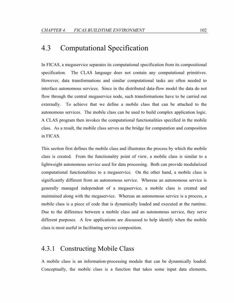
CHAPTER 4. FICAS BUILDTIME ENVIRONMENT 102
4.3 Computational Specification
In FICAS, a megaservice separates its computational specification from its compositional
specification. The CLAS language does not contain any computational primitives.
However, data transformations and similar computational tasks are often needed to
interface autonomous services. Since in the distributed data-flow model the data do not
flow through the central megaservice node, such transformations have to be carried out
externally. To achieve that we define a mobile class that can be attached to the
autonomous services. The mobile class can be used to build complex application logic.
A CLAS program then invokes the computational functionalities specified in the mobile
class. As a result, the mobile class serves as the bridge for computation and composition
in FICAS.
This section first defines the mobile class and illustrates the process by which the mobile
class is created. From the functionality point of view, a mobile class is similar to a
lightweight autonomous service used for data processing. Both can provide modularized
computational functionalities to a megaservice. On the other hand, a mobile class is
significantly different from an autonomous service. Whereas an autonomous service is
generally managed independent of a megaservice, a mobile class is created and
maintained along with the megaservice. Whereas an autonomous service is a process, a
mobile class is a piece of code that is dynamically loaded and executed at the runtime.
Due to the difference between a mobile class and an autonomous service, they serve
different purposes. A few applications are discussed to help identify when the mobile
class is most useful in facilitating service composition.
4.3.1 Constructing Mobile Class
A mobile class is an information-processing module that can be dynamically loaded.
Conceptually, the mobile class is a function that takes some input data elements,

CHAPTER 4. FICAS BUILDTIME ENVIRONMENT 103
performs certain operations, and then outputs a new data element. For instance,
, represents a mobile class named f that takes three data elements as
input and produces an output data element y.
),,( 321 xxxfy =
Java is chosen as the specification language for mobile classes in FICAS. Such selection
is made for a few reasons. First, Java is a general programming language that is suitable
for specifying computational intensive tasks. There are many available standard libraries
that provide a wide range of computational functionalities. Second, Java has extensive
support for portability. Java programs can be executed on any platform that incorporates
a Java virtual machine. Third, Java supports dynamic linking and loading. Java class
files are object files rather than executables in the traditional senses. Linking is
performed when the Java class files are loaded onto the Java virtual machine. Compiled
into a Java class, the mobile class can be dynamically loaded at runtime.
Figure 4.4 defines the MobileClass interface. All mobile classes implement the interface.
The interface contains a single function that represents the functionality of a mobile class.
The execute() function takes a vector of data elements as the input and generates a data
element as the output. The execute() function is overloaded by the mobile class to
provide specific processing functionality. Figure 4.5 shows the definition of the
DataElement class, which represents the data elements used in FICAS. The class
definition is part of the Java library of FICAS, which is also used to build the
autonomous services. Since the autonomous services and the mobile classes use the same
representation for the data elements, the megaservice can pass the data elements between
its compositional specification and computational specification. Internally, a data
element is represented in XML. There are two constructors for DataElement, one for
creating an empty data element, the other for creating a data element based on its XML
representation. The class provides functions to query the type and the size of the data
element. In the case that the data element is of a primitive type (i.e., boolean, integer,
real, or string), functions are provided to set, fetch and compare values for the data
element. Otherwise, the content of the data element can be fetched as a byte array.
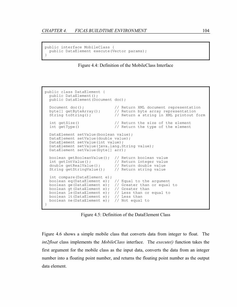
CHAPTER 4. FICAS BUILDTIME ENVIRONMENT 104
public interface MobileClass public DataElement execute(Vector params);
Figure 4.4: Definition of the MobileClass Interface
public class DataElement public DataElement(); public DataElement(Document doc); Document doc(); // Return XML document representation byte[] getByteArray(); // Return byte array representation String toString(); // Return a string in XML printout form int getSize() // Return the size of the element int getType() // Return the type of the element DataElement setValue(boolean value); DataElement setValue(double value); DataElement setValue(int value); DataElement setValue(java.lang.String value); DataElement setValue(byte[] arr); boolean getBooleanValue(); // Return boolean value int getIntValue(); // Return integer value double getRealValue(); // Return double value String getStringValue(); // Return string value int compare(DataElement e); boolean eq(DataElement e); // Equal to the argument boolean ge(DataElement e); // Greater than or equal to boolean gt(DataElement e); // Greater than boolean le(DataElement e); // Less than or equal to boolean lt(DataElement e); // Less than boolean ne(DataElement e); // Not equal to
Figure 4.5: Definition of the DataElement Class
Figure 4.6 shows a simple mobile class that converts data from integer to float. The
int2float class implements the MobileClass interface. The execute() function takes the
first argument for the mobile class as the input data, converts the data from an integer
number into a floating point number, and returns the floating point number as the output
data element.
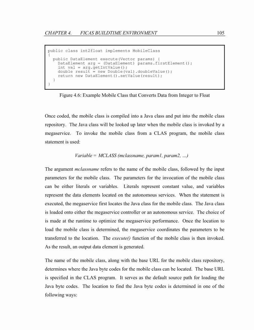
CHAPTER 4. FICAS BUILDTIME ENVIRONMENT 105
public class int2float implements MobileClass public DataElement execute(Vector params) DataElement arg = (DataElement) params.firstElement(); int val = arg.getIntValue(); double result = new Double(val).doubleValue(); return new DataElement().setValue(result);
Figure 4.6: Example Mobile Class that Converts Data from Integer to Float
Once coded, the mobile class is compiled into a Java class and put into the mobile class
repository. The Java class will be looked up later when the mobile class is invoked by a
megaservice. To invoke the mobile class from a CLAS program, the mobile class
statement is used:
Variable = MCLASS (mclassname, param1, param2, …)
The argument mclassname refers to the name of the mobile class, followed by the input
parameters for the mobile class. The parameters for the invocation of the mobile class
can be either literals or variables. Literals represent constant value, and variables
represent the data elements located on the autonomous services. When the statement is
executed, the megaservice first locates the Java class for the mobile class. The Java class
is loaded onto either the megaservice controller or an autonomous service. The choice of
is made at the runtime to optimize the megaservice performance. Once the location to
load the mobile class is determined, the megaservice coordinates the parameters to be
transferred to the location. The execute() function of the mobile class is then invoked.
As the result, an output data element is generated.
The name of the mobile class, along with the base URL for the mobile class repository,
determines where the Java byte codes for the mobile class can be located. The base URL
is specified in the CLAS program. It serves as the default source path for loading the
Java byte codes. The location to find the Java byte codes is determined in one of the
following ways:

CHAPTER 4. FICAS BUILDTIME ENVIRONMENT 106
1. If the name of the mobile class starts with “http://”, then the URL for loading the Java
byte codes can be obtained by appending “.class” to the name of the mobile class.
For example, if the mobile class name is “http://mobile.class.repository/int2float”,
then the Java class file for the mobile class can be found at
“http://mobile.class.repository/int2float.class”.
2. If the name of the mobile class is a normal string, then the URL for loading the Java
byte codes can be obtained by prefixing the base URL and appending “.class” to the
name of the mobile class. For example, if the base class path for the megaservice is
“http://mobile.class.repository”, then the Java class file for the mobile class int2float
can be located at “http://mobile.class.repository/int2float.class”.
4.3.2 Mobile Class for Data Processing
To demonstrate the capability of the mobile class, we examine how the mobile class is
used to support data processing. Specifically, we look at examples using relational data
operations. Table 4.7 lists the relational operators, their relational algebra
representations, and the corresponding mobile class interfaces. The relational operators
conduct processing on one or more input relations, and generate a new relation as the
output. A mobile class is constructed for each relational operator. The input relations of
the relational operator are the input parameters to the mobile class, and the value returned
by the mobile class corresponds to the output relation of the relational operator. For the
mobile classes, the input and the output relations are encapsulated as data elements. The
encoding of the relations into data elements is predefined and understood by the mobile
classes. Various schemes may be used. For instance, Peng et al discussed using XML as
the data representation standard for encoding scientific data [73], including relational
tables.
Complex relational expressions can be built recursively by combining relational operators
on expressions:
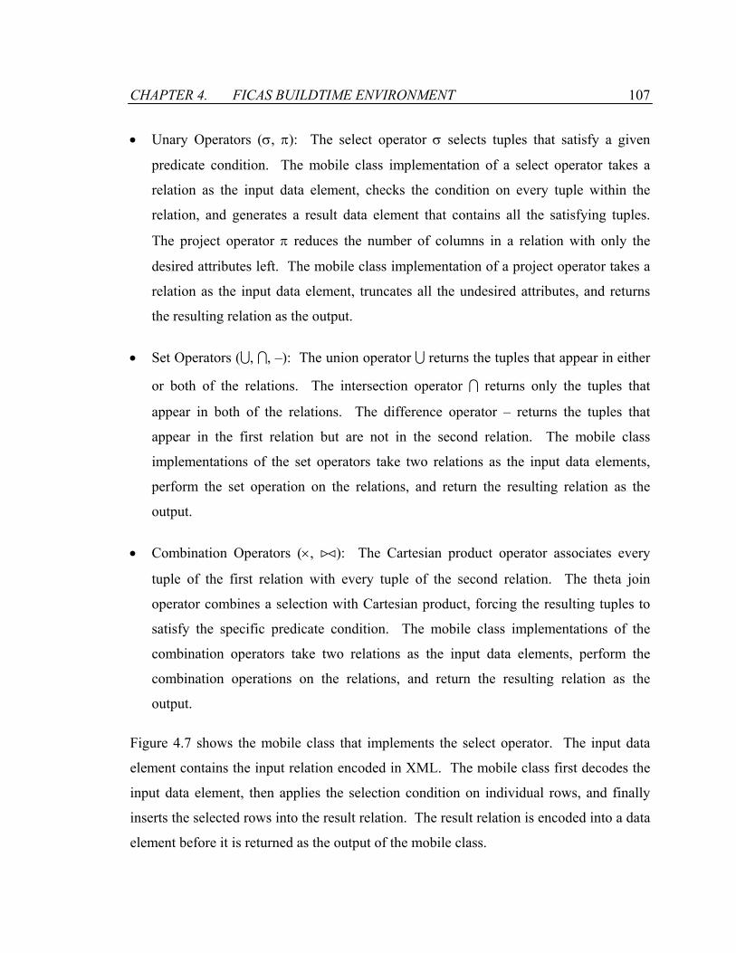
CHAPTER 4. FICAS BUILDTIME ENVIRONMENT 107
• Unary Operators (σ, π): The select operator σ selects tuples that satisfy a given
predicate condition. The mobile class implementation of a select operator takes a
relation as the input data element, checks the condition on every tuple within the
relation, and generates a result data element that contains all the satisfying tuples.
The project operator π reduces the number of columns in a relation with only the
desired attributes left. The mobile class implementation of a project operator takes a
relation as the input data element, truncates all the undesired attributes, and returns
the resulting relation as the output.
• Set Operators (U, I, –): The union operator U returns the tuples that appear in either
or both of the relations. The intersection operator I returns only the tuples that
appear in both of the relations. The difference operator – returns the tuples that
appear in the first relation but are not in the second relation. The mobile class
implementations of the set operators take two relations as the input data elements,
perform the set operation on the relations, and return the resulting relation as the
output.
• Combination Operators (×, ><): The Cartesian product operator associates every
tuple of the first relation with every tuple of the second relation. The theta join
operator combines a selection with Cartesian product, forcing the resulting tuples to
satisfy the specific predicate condition. The mobile class implementations of the
combination operators take two relations as the input data elements, perform the
combination operations on the relations, and return the resulting relation as the
output.
Figure 4.7 shows the mobile class that implements the select operator. The input data
element contains the input relation encoded in XML. The mobile class first decodes the
input data element, then applies the selection condition on individual rows, and finally
inserts the selected rows into the result relation. The result relation is encoded into a data
element before it is returned as the output of the mobile class.

CHAPTER 4. FICAS BUILDTIME ENVIRONMENT 108
Table 4.7: Relational Operators and Their Corresponding Mobile Classes
Operator Relational Representation Mobile Class
Select O = σ cond (A) O = MCLASS(“select”, A)
Project O = π attr (A) O = MCLASS(“project”, A)
Union O = A U B O = MCLASS(“union”, A, B)
Intersect O = A I B O = MCLASS(“intersect”, A, B)
Difference O = A – B O = MCLASS(“difference”, A, B)
Cartesian product O = A × B O = MCLASS(“cartesian”, A, B)
Theta join O = A ><cond B O = MCLASS(“join”, A, B)
public class select implements MobileClass public DataElement execute(Vector params) DataElement arg = (DataElement)params.elementAt(0); Element source = (Element)arg.doc().getElementsByTagName("TABLE").item(0); NodeList rows = source.getElementsByTagName("ROW"); Document result = new DocumentImpl(); Element root = result.createElement("TABLE"); for (int i=0; i<rows.getLength(); i++) Element row = (Element) rows.item(i); if (condition_is_met(row)) root.appendChild(InsertRow(result, row)); result.appendChild(root); return new DataElement(result); ...
Figure 4.7: Example Mobile Class that Implements the Select Operator
CHAPTER 4. FICAS BUILDTIME ENVIRONMENT 109
4.3.3 Mobile Class for Type Mediation
Data generated by an autonomous service can be directly used by other autonomous
services if the services share the same data types, formats, and granularities, etc.
However, such homogeneity cannot be assumed within a large-scale service composition
infrastructure. Data exist in various types and will continue to appear in different types
that suit different applications. The output data of one autonomous service needs to be
converted to conform to the type of the input data of another autonomous service.
Traditionally, an autonomous service serving as type broker or a distributed network of
type brokers can be used to mediate the difference among data in various formats [63].
The type brokers can use data in unknown formats and convert them to known formats
for the information client. The type brokers serve as proxies connecting client requests
with appropriate source services. A type graph is used to figure out the chain of
necessary conversions. An example of automating this process can be seen in [18].
There are two issues associated with using type brokers: efficiency and availability.
First, the use of type brokers for type mediation can be inefficient. Large amount of data
are forwarded among the brokers, especially when a chain of conversions is involved.
Figure 4.8(a) presents an example of data-flows in the type-broker architecture. Data
from the source service are represented in the type T1, and the destination service
consumes data in the type T3. Two type brokers are employed to convert source data
from the type T1 to the type T3. Potentially large amount of data are passed among the
type brokers. Second, the necessary type brokers may not exist for the desired data type.
Since there are a large number of data formats, it is impractical to prepare a
comprehensive set of type brokers covering all existing and future data types.
Megaprogrammers therefore need to create and maintain new type brokers to conduct
desired type mediations. However, the task of owning the autonomous services is in
conflict with the role and the expertise of the megaprogrammers. Type brokers ought to
be maintained independent of the megaservices.
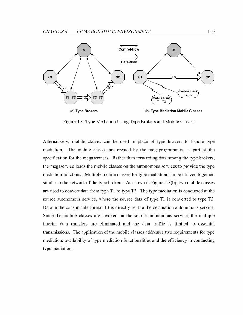
CHAPTER 4. FICAS BUILDTIME ENVIRONMENT 110
M
S1
(a) Type Brokers
T1
T2T1_T2 T2_T3
S2
T3
M
S1
(b) Type Mediation Mobile Classes
T3 S2
mobile classT1_T2
mobile classT2_T3
Control-flow
Data-flow
Figure 4.8: Type Mediation Using Type Brokers and Mobile Classes
Alternatively, mobile classes can be used in place of type brokers to handle type
mediation. The mobile classes are created by the megaprogrammers as part of the
specification for the megaservices. Rather than forwarding data among the type brokers,
the megaservice loads the mobile classes on the autonomous services to provide the type
mediation functions. Multiple mobile classes for type mediation can be utilized together,
similar to the network of the type brokers. As shown in Figure 4.8(b), two mobile classes
are used to convert data from type T1 to type T3. The type mediation is conducted at the
source autonomous service, where the source data of type T1 is converted to type T3.
Data in the consumable format T3 is directly sent to the destination autonomous service.
Since the mobile classes are invoked on the source autonomous service, the multiple
interim data transfers are eliminated and the data traffic is limited to essential
transmissions. The application of the mobile classes addresses two requirements for type
mediation: availability of type mediation functionalities and the efficiency in conducting
type mediation.
CHAPTER 4. FICAS BUILDTIME ENVIRONMENT 111
4.3.4 Mobile Class for Extraction Model Mediation
Autonomous services can produce data with a wide variety of extraction models [81].
Most megaservices have a set of upstream autonomous services generating data that is
consumed by a set of downstream autonomous services. When there is a mismatch
between how the data is produced and later consumed, extraction model mediation plays
an important role. For example, an upstream service might produce data progressively,
while the downstream service requires that the data arrive as a whole relation. Mobile
classes can be used to prepare the data for different extraction models. A taxonomy of
extraction models for autonomous services that produce outputs based on specific inputs
is presented in [81]. The taxonomy is based on three binary factors: partial extraction,
runtime service status, and runtime result status. The three binary factors combine to
form eight basic types of data extraction methods, including familiar and obvious
methods (e.g., SQL cursors and RPC), and some less obvious methods (e.g., semantic
partial extraction and progressive extraction).
Mobile classes can help autonomous services extend their support for extraction models.
For instance, consider an autonomous service that is not implemented to support the
partial extraction model presented in [81]. The autonomous service produces three
outputs, A, B, and C, but has to deliver them as a single opaque object X. Downstream
autonomous services have to consume the object X in whole. A mobile class can mimic
partial extraction by extracting only the components of X desired by downstream
services. The behavior of the mobile class is functionally similar to the relational mobile
class for the projection operation. This simple process can be further coupled with
selection and sorting predicates for producing many different types of behaviors. With
mobile classes, opaque data can be filtered, sorted, transmission delayed, projected, split,
and recombined.
Extraction model mediation is required when the output model of an upstream
autonomous service is incompatible with the input model of a downstream autonomous

CHAPTER 4. FICAS BUILDTIME ENVIRONMENT 112
service. An example of this incompatibility was mentioned earlier: an upstream
autonomous service delivers an SQL cursor, but the downstream autonomous service
expects a relation. Such a simple mismatch of extraction models will stymie any
upstream-downstream pair. This is when mobile classes become valuable. A mobile
class is constructed to scroll the SQL cursor to fill a complete relation, and return the
relation as the output. The mobile class is loaded onto the upstream autonomous service
to mediate the output data for the downstream autonomous service. As the result, a
megaservice is able to utilize both autonomous services despite the difference in their
extraction models.
Autonomous services are invariably built with the expected audience in mind. However,
they may not be able to cover all the potential audiences. Even when there is a type and
domain match between the upstream and downstream autonomous services, the
difference in their extraction models can provide a seemingly insurmountable block. The
application of mobile classes is a solution to extraction model incompatibilities.
4.4 Summary
This chapter reviews the buildtime environment of FICAS that allows the composition of
the autonomous services to be specified, verified, and converted into executables. The
composition represents a megaservice that is defined by the formal specifications. There
are two aspects of the megaservice that the specifications define: (1) the compositional
aspect that specifies the interactions among the autonomous services, and (2) the
computational aspect that specifies the processing of the data utilized by the autonomous
services. The specifications are written in source programs. The buildtime environment
provides a set of tools that compile the source programs into executables for the runtime
environment of FICAS.
CHAPTER 4. FICAS BUILDTIME ENVIRONMENT 113
The CLAS language is introduced as the high-level compositional language to support
the compositional specification of megaservices. The CLAS language is based on the
CLAM language and inherits many traits from CLAM [80]. First, CLAS uses the IWIM
invocation model. The megaservice is the general contractor, and the autonomous service
is the subcontractor that is accessed with input parameters and with return values.
Second, CLAS breaks up the traditional remote procedure call to the autonomous service
into several statements. Asynchronicity is obtained to allow parallel invocations of
remote methods from a sequential client. Third, CLAS is designed to be purely
compositional. It has a limited set of control constructs and supports a restricted set of
data types. On the other hand, CLAS improves on CLAM in many areas. First, CLAS
eliminates a few primitives from CLAM to make the language even simpler.
Furthermore, CLAS introduces the input parameter to facilitate the multi-tiered service
composition. Finally, CLAS provides the megaservice the ability to perform
computation using the mobile class. Overall, CLAS is a compositional language that
combines simplicity, expressive power, and performance.
The mobile class is introduced to support computational specification of megaservices.
Using the mobile class, a megaservice can separate its compositional specification from
its computational specification. Implemented in Java, the mobile class supports a wide
range of computational functionalities. Examples are shown to demonstrate how the
mobile class is used to perform data processing, type mediation, and extraction model
mediation. There are a couple of key benefits of using the mobile class to conduct
computational processing. First, the mobile class is flexible in providing computational
functionalities. Since the mobile class is specified along with the megaservice, it can be
easily modified to satisfy the specific requirement by the megaservice. Second, the
mobile class is efficient in execution. As we have demonstrated in the type mediation
example (in Figure 4.8), mobile classes can be used to reduce the amount of data traffic
among the autonomous services. As the mobile class can be dynamically loaded, a
megaservice can optimize its performance by placing the mobile class at an appropriate
location to minimize the communication traffic.

Chapter 5
Runtime Environment of FICAS
This chapter describes the design of the runtime environment of FICAS, which is
responsible for the execution of the megaservice executables generated by the buildtime
environment. Various features are designed and implemented to support the scalability
of the service composition infrastructure and to achieve high performance of the
megaservices. FICAS can incorporate a large number of autonomous services, which can
join and leave the service composition infrastructure without affecting other autonomous
services. With respect to performance, the execution of the megaservices takes
advantage of the distribution of the data-flows in FICAS and is supported by various
features such as the autonomous service metamodel, the ASAP protocol, the CLAS
language, and the mobile class. FICAS is particularly suitable for conducting service
composition where large volume of data exchange is involved among the autonomous
services. We demonstrate the use of the FICAS infrastructure with a construction project
management application.
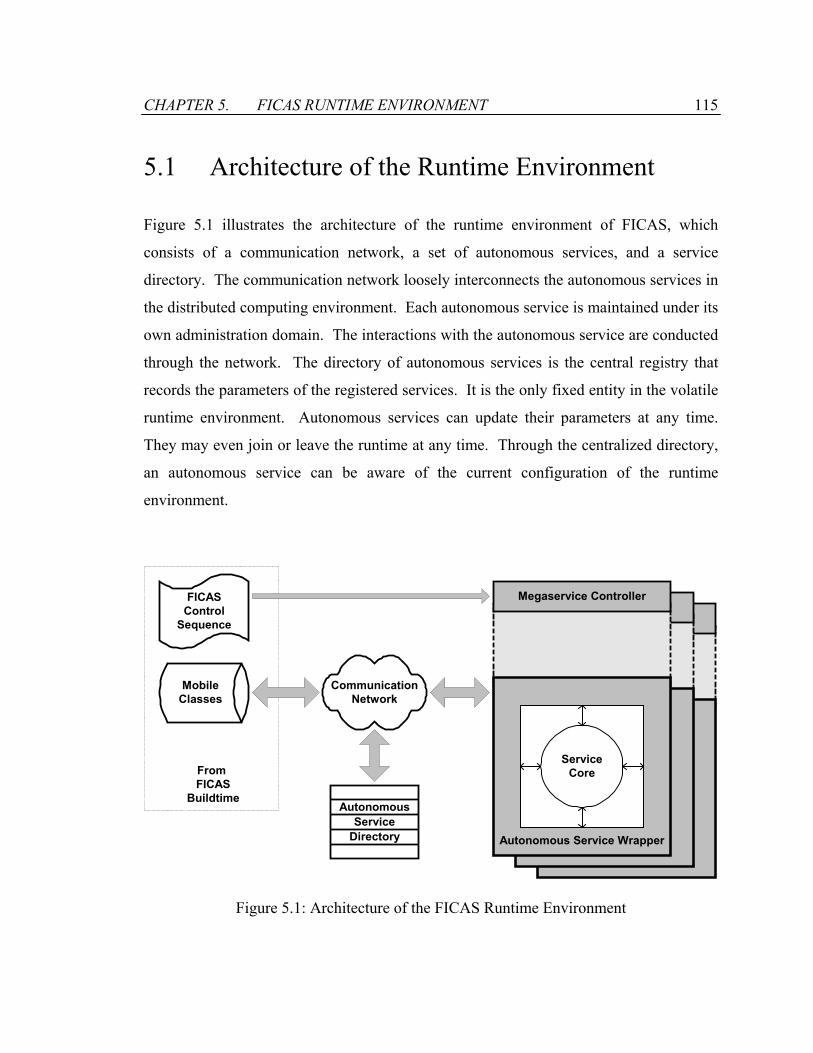
CHAPTER 5. FICAS RUNTIME ENVIRONMENT 115
5.1 Architecture of the Runtime Environment
Figure 5.1 illustrates the architecture of the runtime environment of FICAS, which
consists of a communication network, a set of autonomous services, and a service
directory. The communication network loosely interconnects the autonomous services in
the distributed computing environment. Each autonomous service is maintained under its
own administration domain. The interactions with the autonomous service are conducted
through the network. The directory of autonomous services is the central registry that
records the parameters of the registered services. It is the only fixed entity in the volatile
runtime environment. Autonomous services can update their parameters at any time.
They may even join or leave the runtime at any time. Through the centralized directory,
an autonomous service can be aware of the current configuration of the runtime
environment.
Megaservice Controller
ServiceCore
Megaservice Controller
ServiceCore
CommunicationNetwork
AutonomousService
Directory
FICASControl
Sequence
MobileClasses
Megaservice Controller
ServiceCore
Autonomous Service Wrapper
From FICAS
Buildtime
Figure 5.1: Architecture of the FICAS Runtime Environment

CHAPTER 5. FICAS RUNTIME ENVIRONMENT 116
The control sequence and the mobile classes generated by the buildtime environment for
the megaservice are the inputs for the runtime environment of FICAS. The control
sequence specifies the control-flow of the megaservice. It is sent to a megaservice
controller to be executed. The megaservice controller is attached to the autonomous
service wrapper. This design enables each autonomous service to serve as the
megaservice controller. The deployment of the autonomous services implicitly provides
the availability of the megaservice controllers. The mobile classes specify the
computational routines involved in the megaservice. They reside in the mobile class
repository. The mobile classes are dynamically loaded by the autonomous services when
the mobile classes are invoked within the megaservice.
The runtime environment of FICAS has a highly scalable architecture. At its minimum,
the runtime can consist just one autonomous service, along with the service directory. On
the other hand, the runtime environment can be expanded by simply plugging in
additional autonomous services into the communication network and registering the
autonomous services with the service directory.
5.1.1 Autonomous Service Directory
The autonomous service directory is the central facility for the registration and discovery
of autonomous services. The megaservice refers to an autonomous service by its name.
The directory maps the name of the autonomous service to the information needed by the
runtime environment, such as the location of the autonomous service on the network and
the TCP/IP port. The directory provides a level of indirection that allows autonomous
services to be easily added, modified, or replaced without making any changes to the
megaservice.
Each autonomous service is responsible for informing the centralized directory of its
parameters. Figure 5.2 shows a sample autonomous service directory that contains the
registrations of five autonomous services. XML is chosen as the representation format
CHAPTER 5. FICAS RUNTIME ENVIRONMENT 117
for the autonomous service directory because the data contained in directory is
semistructured [20]. Each autonomous service registration is represented by an XML
element tagged “SERVICE”. The child elements of the SERVICE element specify the
parameters of the autonomous service. There are three mandatory child elements: the
NAME element contains the name of the autonomous service, the SERVER element
contains the IP address of the server machine, and the PORT element contains the TCP/IP
port to which the service listens. The autonomous service can also register other
parameters with the directory for look up during the runtime. The current
implementation of the runtime does not utilize any of the optional service parameters.
However, the ability to register these parameters makes the runtime extendable. Sample
et al. have demonstrated an example where the service parameters are used for scheduling
autonomous services under uncertainty [82]. The cost, the expected completion time, and
other information of the autonomous services are used to help the megaservice determine
which autonomous services to invoke. For the example shown in Figure 5.2, the
autonomous service named ServicePsl has registered two additional parameters: COST
representing what the autonomous service provider will charge for the service, and TIME
representing the estimated length of time to complete the service. These parameters can
be used in the future to support scheduling of the autonomous services under uncertainty.
The address of the service directory is known a priori to all the autonomous services. An
autonomous service joins the composition infrastructure by registering itself with the
directory. The autonomous service is also responsible for maintaining the accuracy of its
entry within the directory. Whenever any service parameter is changed, the autonomous
service needs to notify and update the directory. The self-maintenance model allows the
service composition infrastructure to accommodate a large number of independent
autonomous services.
The service directory described here can be considered as a strip down version of the
general directory service, such as the UDDI [5] and the JNDI [45]. It is assumed in
FICAS that the autonomous service name is used as the index for the directory, i.e., the
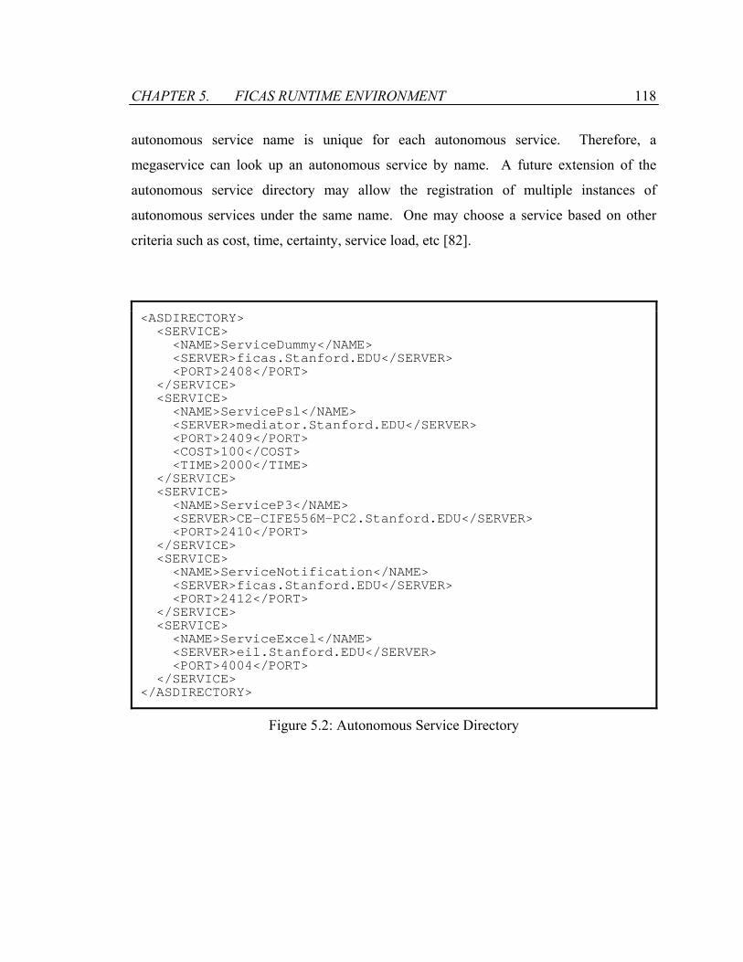
CHAPTER 5. FICAS RUNTIME ENVIRONMENT 118
autonomous service name is unique for each autonomous service. Therefore, a
megaservice can look up an autonomous service by name. A future extension of the
autonomous service directory may allow the registration of multiple instances of
autonomous services under the same name. One may choose a service based on other
criteria such as cost, time, certainty, service load, etc [82].
<ASDIRECTORY> <SERVICE> <NAME>ServiceDummy</NAME> <SERVER>ficas.Stanford.EDU</SERVER> <PORT>2408</PORT> </SERVICE> <SERVICE> <NAME>ServicePsl</NAME> <SERVER>mediator.Stanford.EDU</SERVER> <PORT>2409</PORT> <COST>100</COST> <TIME>2000</TIME> </SERVICE> <SERVICE> <NAME>ServiceP3</NAME> <SERVER>CE-CIFE556M-PC2.Stanford.EDU</SERVER> <PORT>2410</PORT> </SERVICE> <SERVICE> <NAME>ServiceNotification</NAME> <SERVER>ficas.Stanford.EDU</SERVER> <PORT>2412</PORT> </SERVICE> <SERVICE> <NAME>ServiceExcel</NAME> <SERVER>eil.Stanford.EDU</SERVER> <PORT>4004</PORT> </SERVICE> </ASDIRECTORY>
Figure 5.2: Autonomous Service Directory
CHAPTER 5. FICAS RUNTIME ENVIRONMENT 119
5.1.2 Megaservice Controller
The megaservice controller is the functional unit that interprets the control sequence
generated by the buildtime environment and coordinates the execution of the
megaservice. One and only one megaservice controller is responsible for each
megaservice. As shown in Figure 5.3, the megaservice controller is attached to the
autonomous service wrapper. Together, they form a “local” autonomous service. The
binding of the wrapper and the megaservice controller allows many components built in
the wrapper to be reused. The wrapper and the megaservice controller share the input
and output event queues for receiving and sending events. They also share the input and
output data containers for exchanging data elements with other autonomous services.
The megaservice controller consists of five components: the Control Manager, the ASAP
Event Receiver, the Variable Cache, the Flow Dependency Table, and the Outgoing
Event Pool. The components work collaboratively to interpret the control elements
contained in the input control sequence. The control elements are classified into four
categories based on the types of CLAS statements they represent: the assignment
statement, the conditional statement, the autonomous service statement, and the mobile
class statement. We describe in the rest of this section how the megaservice controller
processes each type of the statements.
5.1.2.1 Processing of the Assignment Statement
The Control Manager reads in a control sequence and interprets one control element at a
time. The control element representing an assignment statement results in an entry in the
Variable Cache. In the case where a literal value is assigned to a variable, an entry is
formed in the Variable Cache that associates the literal value with the variable. In the
case where a variable is assigned to another variable, the value of the right-hand side
variable is looked up from the Variable Cache, and then assigned to the left-hand side
variable in the Variable Cache.

CHAPTER 5. FICAS RUNTIME ENVIRONMENT 120
ASAP Event Receiver
Outgoing Event Pool
FICASControl Sequence
Control Manager
FlowDependency
Table
VariableCache
Megaservice Controller
Autonomous Service Wrapper
FromAutonomous
Services
Input Event Queue
Output Event Q
ueue
Input Data Container
Output Data Container
Service Core
Active Mediator
ToAutonomous
Services
Figure 5.3: Architecture of the Megaservice Controller
CHAPTER 5. FICAS RUNTIME ENVIRONMENT 121
The value of a variable in the Variable Cache can be represented either as a data element
or as a reference to a data element. For instance, a literal value is represented as a data
element, and a data element on a remote autonomous service is represented as a
reference. When the value of a variable is needed by the megaservice (e.g., for
evaluating the boolean predicate of a branch statement), the reference must be
materialized. The data element is loaded into the Variable Cache in the following
process: (1) the Control Manager generates a MAPDATA event to transmit the data
element from the remote autonomous service to the local autonomous service; then, (2)
the remote autonomous service sends the data element to the input data container of the
autonomous service wrapper; and finally, (3) the data element is forwarded to the
Variable Cache.
5.1.2.2 Processing of the Conditional Statement
The conditional statement (i.e., the branch statements and the while loops) consists of a
boolean predicate and a subgroup(s) of statements. When processing the conditional
statement, the Control Manager first evaluates the boolean predicate. The values of the
variables in the predicate are looked up from the Variable Cache. Based on the result of
the evaluation, the Control Manager then determines whether or which subsequent group
of statements is executed.
5.1.2.3 Processing of the Autonomous Service Statement
The autonomous service statements (i.e., SETUP, INVOKE, EXTRACT, and
TERMINATE) are used by the megaservice to interact with the autonomous services.
When processing an autonomous service statement, the Control Manager generates
appropriate ASAP events for the statement, which are put into the Outgoing Event Pool.
At the same time, dependencies among the outgoing ASAP events are formulated into the
Flow Dependency Table. The Outgoing Event Pool utilizes its own thread. An event in
the Outgoing Event Pool is sent out when all the dependencies on the event are resolved.
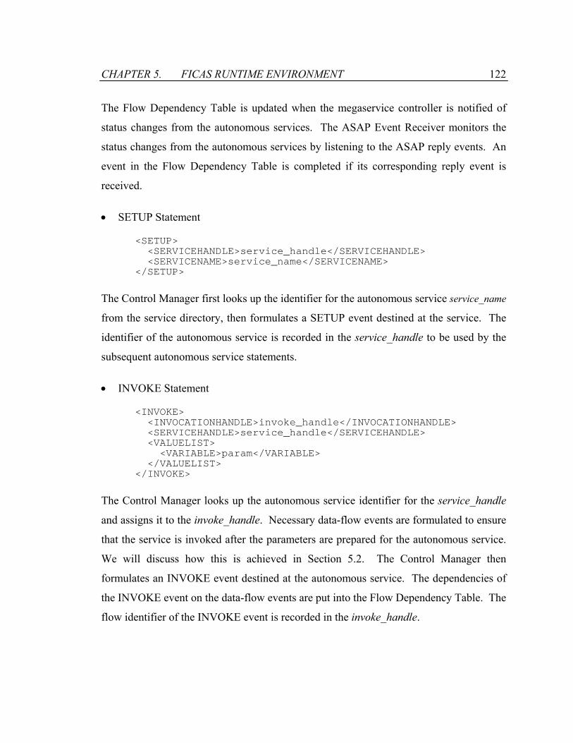
CHAPTER 5. FICAS RUNTIME ENVIRONMENT 122
The Flow Dependency Table is updated when the megaservice controller is notified of
status changes from the autonomous services. The ASAP Event Receiver monitors the
status changes from the autonomous services by listening to the ASAP reply events. An
event in the Flow Dependency Table is completed if its corresponding reply event is
received.
• SETUP Statement
<SETUP> <SERVICEHANDLE>service_handle</SERVICEHANDLE> <SERVICENAME>service_name</SERVICENAME> </SETUP>
The Control Manager first looks up the identifier for the autonomous service service_name
from the service directory, then formulates a SETUP event destined at the service. The
identifier of the autonomous service is recorded in the service_handle to be used by the
subsequent autonomous service statements.
• INVOKE Statement
<INVOKE> <INVOCATIONHANDLE>invoke_handle</INVOCATIONHANDLE> <SERVICEHANDLE>service_handle</SERVICEHANDLE> <VALUELIST> <VARIABLE>param</VARIABLE> </VALUELIST> </INVOKE>
The Control Manager looks up the autonomous service identifier for the service_handle
and assigns it to the invoke_handle. Necessary data-flow events are formulated to ensure
that the service is invoked after the parameters are prepared for the autonomous service.
We will discuss how this is achieved in Section 5.2. The Control Manager then
formulates an INVOKE event destined at the autonomous service. The dependencies of
the INVOKE event on the data-flow events are put into the Flow Dependency Table. The
flow identifier of the INVOKE event is recorded in the invoke_handle.

CHAPTER 5. FICAS RUNTIME ENVIRONMENT 123
• EXTRACT Statement
<EXTRACT> <VARIABLE>variable</VARIABLE> <INVOCATIONHANDLE>invoke_handle</INVOCATIONHANDLE> </EXTRACT>
No ASAP event is generated for the EXTRACT statement. The Control Manager merely
associates the variable with the autonomous service and the flow identifier of the
autonomous service referred by the invoke_handle. When the variable is later utilized,
the Control Manager will be able to form the appropriate data-flow events to obtain the
data element.
• TERMINATE
<TERMINATE> <SERVICEHANDLE>service_handle</SERVICEHANDLE> </TERMINATE>
The Control manager looks up the autonomous service identifier and formulates a
TERMINATE event destined at the autonomous service.
The scheme used by the Control Manager to generate the ASAP events and their
dependencies is not unique. Different schemes produce different control-flow and data-
flow patterns for executing the megaservice. Section 5.2 will describe a scheme that
produces distributed data-flows among the autonomous services.
5.1.2.4 Processing of the Mobile Class Statement
The FICAS control element that represents the mobile class statement has the following
form:
<MCLASS> <VARIABLE>result</VARIABLE> <MCLASSNAME>mobileclass</MCLASSNAME> <VALUELIST> <VARIABLE>param</VARIABLE> </VALUELIST> </MCLASS>

CHAPTER 5. FICAS RUNTIME ENVIRONMENT 124
As a mobile class can be dynamically loaded, it can be executed on many potential
locations. One scenario is to carry out the execution on the local autonomous service. In
this case, the Control Manager notifies the Active Mediator to load the Java class for the
mobile class. At the same time, data-flow events are issued by the Control Manager to
transfer the parameters for the mobile class to the local autonomous service. The mobile
class is then executed, and the data element generated by the execution is assigned to the
result variable.
Another scenario is to carry out the execution of the mobile class on a remote
autonomous service. In this case, the Control Manager first identifies an autonomous
service that will execute the mobile class. The Control Manager then formulates
appropriate data-flow events to transfer the parameters to the autonomous service.
Finally, the Control Manager issues a mobile class event to instruct the autonomous
service to load and execute the mobile class. In addition, the Control Manager associates
the result variable with the result of the mobile class invocation. This scenario is only
possible if the autonomous service supports the execution of the mobile classes. Section
5.3 will discuss in further detail how such support is provided by the autonomous
services in FICAS.
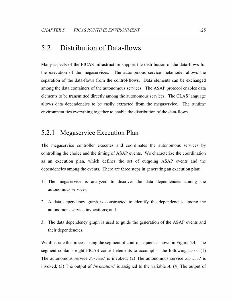
CHAPTER 5. FICAS RUNTIME ENVIRONMENT 125
5.2 Distribution of Data-flows
Many aspects of the FICAS infrastructure support the distribution of the data-flows for
the execution of the megaservices. The autonomous service metamodel allows the
separation of the data-flows from the control-flows. Data elements can be exchanged
among the data containers of the autonomous services. The ASAP protocol enables data
elements to be transmitted directly among the autonomous services. The CLAS language
allows data dependencies to be easily extracted from the megaservice. The runtime
environment ties everything together to enable the distribution of the data-flows.
5.2.1 Megaservice Execution Plan
The megaservice controller executes and coordinates the autonomous services by
controlling the choice and the timing of ASAP events. We characterize the coordination
as an execution plan, which defines the set of outgoing ASAP events and the
dependencies among the events. There are three steps in generating an execution plan:
1. The megaservice is analyzed to discover the data dependencies among the
autonomous services;
2. A data dependency graph is constructed to identify the dependencies among the
autonomous service invocations; and
3. The data dependency graph is used to guide the generation of the ASAP events and
their dependencies.
We illustrate the process using the segment of control sequence shown in Figure 5.4. The
segment contains eight FICAS control elements to accomplish the following tasks: (1)
The autonomous service Service1 is invoked; (2) The autonomous service Service2 is
invoked; (3) The output of Invocation1 is assigned to the variable A; (4) The output of
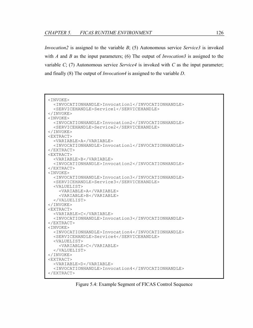
CHAPTER 5. FICAS RUNTIME ENVIRONMENT 126
Invocation2 is assigned to the variable B; (5) Autonomous service Service3 is invoked
with A and B as the input parameters; (6) The output of Invocation3 is assigned to the
variable C; (7) Autonomous service Service4 is invoked with C as the input parameter;
and finally (8) The output of Invocation4 is assigned to the variable D.
<INVOKE> <INVOCATIONHANDLE>Invocation1</INVOCATIONHANDLE> <SERVICEHANDLE>Service1</SERVICEHANDLE> </INVOKE> <INVOKE> <INVOCATIONHANDLE>Invocation2</INVOCATIONHANDLE> <SERVICEHANDLE>Service2</SERVICEHANDLE> </INVOKE> <EXTRACT> <VARIABLE>A</VARIABLE> <INVOCATIONHANDLE>Invocation1</INVOCATIONHANDLE> </EXTRACT> <EXTRACT> <VARIABLE>B</VARIABLE> <INVOCATIONHANDLE>Invocation2</INVOCATIONHANDLE> </EXTRACT> <INVOKE> <INVOCATIONHANDLE>Invocation3</INVOCATIONHANDLE> <SERVICEHANDLE>Service3</SERVICEHANDLE> <VALUELIST> <VARIABLE>A</VARIABLE> <VARIABLE>B</VARIABLE> </VALUELIST> </INVOKE> <EXTRACT> <VARIABLE>C</VARIABLE> <INVOCATIONHANDLE>Invocation3</INVOCATIONHANDLE> </EXTRACT> <INVOKE> <INVOCATIONHANDLE>Invocation4</INVOCATIONHANDLE> <SERVICEHANDLE>Service4</SERVICEHANDLE> <VALUELIST> <VARIABLE>C</VARIABLE> </VALUELIST> </INVOKE> <EXTRACT> <VARIABLE>D</VARIABLE> <INVOCATIONHANDLE>Invocation4</INVOCATIONHANDLE> </EXTRACT>
Figure 5.4: Example Segment of FICAS Control Sequence
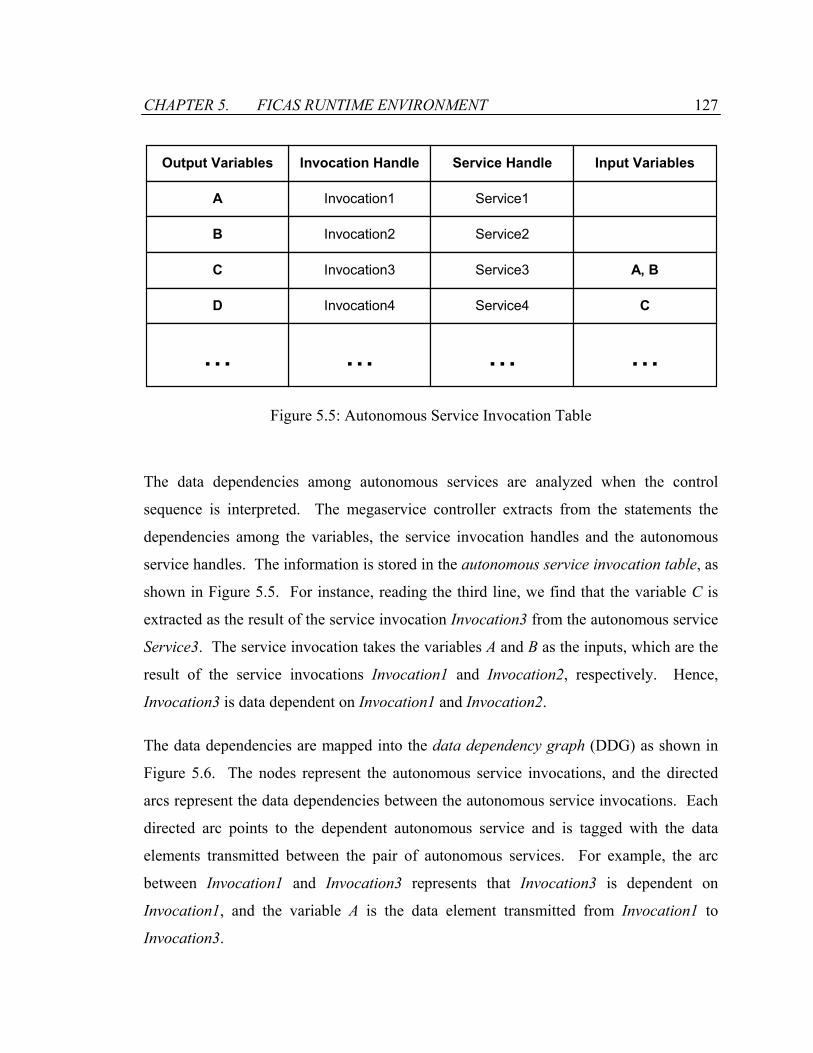
CHAPTER 5. FICAS RUNTIME ENVIRONMENT 127
Invocation Handle Service Handle
Invocation1 Service1
Invocation2 Service2
Invocation3 Service3
Invocation4 Service4
... ...
Output Variables
A
B
C
D
...
Input Variables
A, B
C
...
Figure 5.5: Autonomous Service Invocation Table
The data dependencies among autonomous services are analyzed when the control
sequence is interpreted. The megaservice controller extracts from the statements the
dependencies among the variables, the service invocation handles and the autonomous
service handles. The information is stored in the autonomous service invocation table, as
shown in Figure 5.5. For instance, reading the third line, we find that the variable C is
extracted as the result of the service invocation Invocation3 from the autonomous service
Service3. The service invocation takes the variables A and B as the inputs, which are the
result of the service invocations Invocation1 and Invocation2, respectively. Hence,
Invocation3 is data dependent on Invocation1 and Invocation2.
The data dependencies are mapped into the data dependency graph (DDG) as shown in
Figure 5.6. The nodes represent the autonomous service invocations, and the directed
arcs represent the data dependencies between the autonomous service invocations. Each
directed arc points to the dependent autonomous service and is tagged with the data
elements transmitted between the pair of autonomous services. For example, the arc
between Invocation1 and Invocation3 represents that Invocation3 is dependent on
Invocation1, and the variable A is the data element transmitted from Invocation1 to
Invocation3.

CHAPTER 5. FICAS RUNTIME ENVIRONMENT 128
Invocation1 Invocation2
Invocation3
Invocation4
A B
C
D
Figure 5.6: Data Dependency Graph
The megaservice execution plan is represented by the event dependency graph (EDG).
The node in the EDG contains an outgoing ASAP event from the megaservice controller.
The arc establishes a predecessor-successor relationship between a pair of ASAP events.
The successor ASAP event can be sent only when the action taken by the predecessor
ASAP event is completed, i.e., the megaservice controller receives the response to the
predecessor ASAP event. The megaservice controller uses the EDG to coordinate the
execution of the megaservice. The ASAP events contained in the EDG nodes are placed
into the Outgoing Event Pool, and the dependencies among the ASAP events are placed
in the Flow Dependency Table.
Different EDGs can be generated that utilize different data-flow models for the execution
of the megaservice. Figure 5.7(a) shows an EDG in which the megaservice controller
serves as the central hub for the data traffic. The EDG is generated by directly translating
the individual statements into the ASAP events. The INVOKE statement is translated
into the MAPDATA events, followed by the INVOKE event. The MAPDATA events
transfer the input data elements from the megaservice controller (i.e., the local
autonomous service) to the destination autonomous service, and the INVOKE event
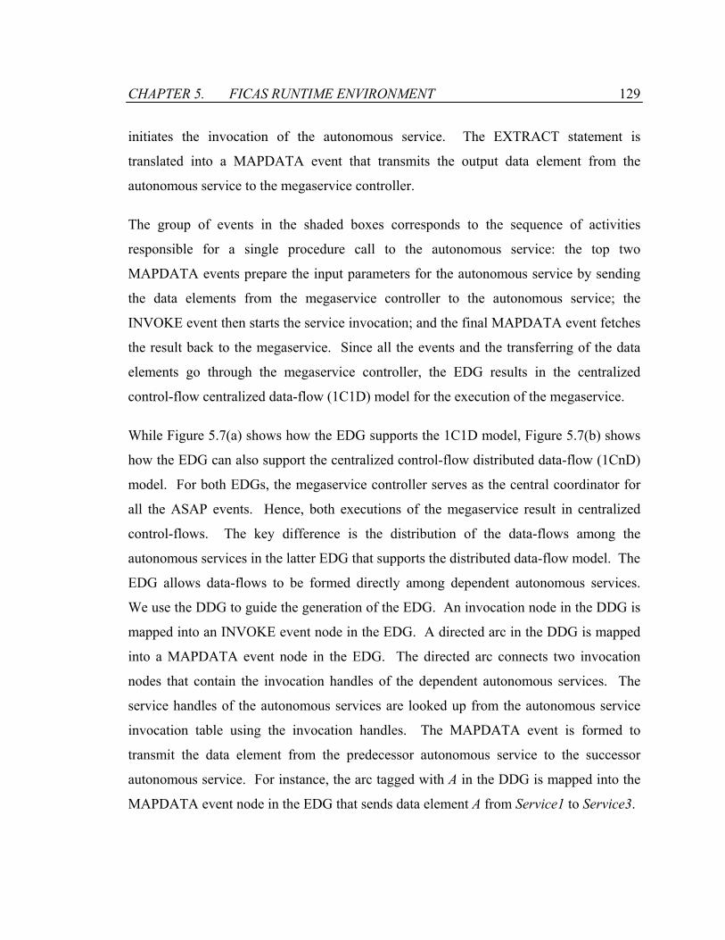
CHAPTER 5. FICAS RUNTIME ENVIRONMENT 129
initiates the invocation of the autonomous service. The EXTRACT statement is
translated into a MAPDATA event that transmits the output data element from the
autonomous service to the megaservice controller.
The group of events in the shaded boxes corresponds to the sequence of activities
responsible for a single procedure call to the autonomous service: the top two
MAPDATA events prepare the input parameters for the autonomous service by sending
the data elements from the megaservice controller to the autonomous service; the
INVOKE event then starts the service invocation; and the final MAPDATA event fetches
the result back to the megaservice. Since all the events and the transferring of the data
elements go through the megaservice controller, the EDG results in the centralized
control-flow centralized data-flow (1C1D) model for the execution of the megaservice.
While Figure 5.7(a) shows how the EDG supports the 1C1D model, Figure 5.7(b) shows
how the EDG can also support the centralized control-flow distributed data-flow (1CnD)
model. For both EDGs, the megaservice controller serves as the central coordinator for
all the ASAP events. Hence, both executions of the megaservice result in centralized
control-flows. The key difference is the distribution of the data-flows among the
autonomous services in the latter EDG that supports the distributed data-flow model. The
EDG allows data-flows to be formed directly among dependent autonomous services.
We use the DDG to guide the generation of the EDG. An invocation node in the DDG is
mapped into an INVOKE event node in the EDG. A directed arc in the DDG is mapped
into a MAPDATA event node in the EDG. The directed arc connects two invocation
nodes that contain the invocation handles of the dependent autonomous services. The
service handles of the autonomous services are looked up from the autonomous service
invocation table using the invocation handles. The MAPDATA event is formed to
transmit the data element from the predecessor autonomous service to the successor
autonomous service. For instance, the arc tagged with A in the DDG is mapped into the
MAPDATA event node in the EDG that sends data element A from Service1 to Service3.
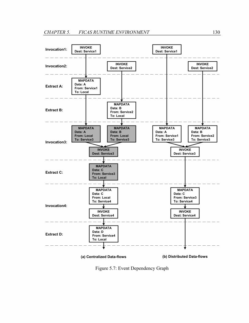
CHAPTER 5. FICAS RUNTIME ENVIRONMENT 130
INVOKEDest: Service1
MAPDATAData: AFrom: Service1To: Local
MAPDATAData: AFrom: LocalTo: Service3
INVOKEDest: Service3
MAPDATAData: CFrom: Service3To: Local
MAPDATAData: CFrom: LocalTo: Service4
INVOKEDest: Service2
MAPDATAData: BFrom: Service2To: Local
MAPDATAData: BFrom: LocalTo: Service3
INVOKEDest: Service4
INVOKEDest: Service1
MAPDATAData: AFrom: Service1To: Service3
INVOKEDest: Service3
MAPDATAData: CFrom: Service3To: Service4
INVOKEDest: Service2
MAPDATAData: BFrom: Service2To: Service3
INVOKEDest: Service4
Invocation1:
Invocation2:
Extract A:
Extract B:
Invocation3:
Extract C:
Invocation4:
(a) Centralized Data-flows (b) Distributed Data-flows
Extract D:MAPDATA
Data: DFrom: Service4To: Local
Figure 5.7: Event Dependency Graph
CHAPTER 5. FICAS RUNTIME ENVIRONMENT 131
5.2.2 Performance Analysis
We have shown in Chapter 2 using a simplified mathematical model that the distribution
of data-flows can improve the performance of the megaservice. While the mathematical
model provides the guidance for designing the FICAS infrastructure, it serves as a crude
approximation for the performance of the megaservice in a real computing environment.
In this section, we measure the performance of a sample megaservice supported by
FICAS. The megaservice is written in the CLAS language, compiled and executed using
the buildtime and runtime environments of FICAS. Different configurations of the
computing environment are used to examine the performance of the megaservice. For
comparison, we implement the same megaservice under a 1C1D service composition
infrastructure.
SOAP is used as the reference platform for the 1C1D model. SOAP [15] is a lightweight
protocol for exchanging information between applications in a distributed computing
environment. It has shown great potential for simplifying web service composition and
the distribution of software using the Internet. There are several implementations of
SOAP. They differ in their support for class binding, ease of use and performance [29].
As one of the popular choices for the SOAP implementations, Apache SOAP [4] is
selected to be our reference implementation. Originally developed by IBM, Apache
SOAP is currently under the management of the Apache Software Foundation. Apache
SOAP is chosen partly because of its popularity, but more importantly because of its
similarities to FICAS. The similarities make the performance comparison between
SOAP and FICAS more relevant:
• Both Apache SOAP and FICAS are implemented in Java. This eliminates the
potential performance discrepancies caused by different implementation languages.
• Both Apache SOAP and FICAS encode data in XML. While XML provides
universality, it comes with a performance penalty. Since XML represents data in
textual format, the data encoded in XML is generally larger in size than the data

CHAPTER 5. FICAS RUNTIME ENVIRONMENT 132
encoded in binary. The decision of using XML as the data representation format is a
trade-off made between universality and performance. For performance comparison
between SOAP and FICAS, it is important to have the infrastructures employ the
same data representation format.
• Both Apache SOAP and FICAS use the Apache Xerces XML parser [99] for
serialization and deserialization of data objects. Serialization and deserialization are
the first and final steps of sending a data object between two autonomous services.
Serialization converts an object into its persistent state, and deserialization converts
an object from its persistent state to its representation in memory. A data object is
transmitted in its serialized form, and deserialized at the destination. Govindaraju et
al have shown that XML parsing and formatting can impact the performance of
SOAP service calls [40]. By using the same XML parser, we eliminate the impact of
serialization and deserialization when comparing the performance between SOAP and
FICAS.
Figure 5.8 illustrates the computing environment for the performance evaluation. Two
autonomous services that focus on data communications are involved. No computational
processing occurs on autonomous services. Autonomous service S1 randomly generates
and returns a string whose size is specified by the input parameter. Autonomous service
S2 takes a string as input and immediately returns without doing anything. Two
megaservices that utilize the autonomous services are constructed. The first megaservice,
MultiService, connects the two autonomous services. It forwards the string generated by
the autonomous service S1 to the autonomous service S2. This megaservice is designed
to examine the impact of the data-flow distribution. The second megaservice,
SingleService, is used to measure the cost of a single service call. The megaservice
simply invokes the autonomous service S1. This megaservice is designed to compare the
implementation efficiency of SOAP and FICAS.

CHAPTER 5. FICAS RUNTIME ENVIRONMENT 133
SwitchMegaService
S1produces
and returns astring value
10mbps
S2consumes a
string
out10mbps
in
(LAN) in = 10 mbps; out = 10 mbps(802.11b) in = 2 mbps; out = 0.5 mbps
MultiService a = S1(size) S2(a)
SingleService a = S1(size)
Figure 5.8: Test Environment for Comparing SOAP and FICAS
The autonomous services and the megaservices are implemented for both SOAP and
FICAS. All Java programs are written and compiled with Sun’s JDK 1.3.0 for the
Microsoft Windows operating system. For SOAP, the autonomous services are
implemented as Java methods whose interfaces are registered with the Apache Tomcat
application server v4.0. S1 is implemented as a method that takes a number as the input,
then allocates and returns a string whose size is the input. S2 is implemented as a method
that reads in a string as input and returns nothing. The megaservices are implemented as
Java applications that invoke the services using the Apache SOAP v2.2 API library.
For FICAS, the autonomous services are wrapped using the Java library described in
Section 3.3. The service cores of the autonomous services are identical in functionality to
their SOAP counterparts. The megaservices are specified as CLAS programs, which are
compiled into FICAS control sequences by the FICAS buildtime. The executions of the
megaservices are conducted by sending the FICAS control sequences to a megaservice
controller.
The tests are performed in a distributed computing environment. The machines are each
configured with a Pentium-III 1 GHz processor and 256 MB RAM, running Windows
CHAPTER 5. FICAS RUNTIME ENVIRONMENT 134
2000 Professional. The autonomous services run on two separate servers connected to a
switch via a LAN. The bandwidth is 10 mbps each way. The megaservices run on the
client machine. Two alternative types of network connections are used to connect the
client machine to the servers. The first scenario attaches the client machine onto the
LAN. The communication bandwidth among all machines is 10 mbps each way. This
scenario resembles many corporate computing environments. The second scenario
connects the client machine to the switch via an 802.11b wireless access point. The
downloading bandwidth is approximately 2 mbps, and the uploading bandwidth is
approximately 0.5 mbps. This scenario resembles a computing center environment,
where servers are connected by high-speed communication links and these servers are
accessed via relatively slower communication links.
The execution times of the megaservices are measured with different settings on the data
volume involved with the megaservices. The data volume is specified by the input
parameter to the autonomous service S1. Figure 5.9 shows the measured performance of
the megaservices when the client machine is connected to the LAN. The following
observations can be made:
• FICAS performs worse than SOAP when the data volume is low. This is expected
and can be explained by two reasons. First, FICAS has more complicated control-
flows than SOAP. FICAS breaks down a single service call in SOAP into multiple
control messages. FICAS also incurs more overheads in initializing and terminating
the autonomous services. Although FICAS achieves performance gains by
distributing the data-flows, the gains are not enough to offset the extra overheads in
the control-flows. Second, it is expected that Apache SOAP, being under
development for quite some time, is better optimized than FICAS in terms of its Java
source codes.

CHAPTER 5. FICAS RUNTIME ENVIRONMENT 135
0
2000
4000
6000
8000
10000
12000
14000
16000
18000
0 100 200 400 800 1600 3200
Data Volume (KB)
Meg
aser
vice
Exe
cutio
n Ti
me
SOAP (SingleService) SOAP (MultiService) FICAS (MultiService)
Figure 5.9: Comparison Between FICAS and SOAP on Local Area Network
• The performance of the FICAS megaservice MultiService is comparable to that of the
SOAP megaservice SingleService. The megaservices are similar in performance
because two megaservices incur the same amount of data-flows. For SingleService,
the string generated by the autonomous service S1 is sent to the megaservice. For
MultiService, the same string is sent from the autonomous service S1 to the
autonomous service S2. The slight difference in the execution times of the
megaservices can be mainly attributed to the difference in their control-flows.
Apache SOAP and FICAS allow us to focus the performance comparison on the data-
flows.
• The execution times of the megaservices increase linearly with respect to the data
volume. Since there is no computational processing on either the autonomous
services or the megaservices, the increase in execution times comes from the
increased data-flows. The execution times approximately double each time the data
volume doubles.
CHAPTER 5. FICAS RUNTIME ENVIRONMENT 136
• FICAS outperforms SOAP when the data volume is high. The larger the data
volume, the bigger is the difference between the execution time of the FICAS
megaservice MultiService and that of the SOAP megaservice MultiService. This is
because the SOAP megaservice incurs twice as much data-flows as the FICAS
megaservice. For the SOAP megaservice, two data messages are used to send the
string from the autonomous service S1 to the autonomous service S2, via the
megaservice controller. For the FICAS megaservice, only one data message is used
to send the string from the autonomous service S1 to the autonomous service S2.
To summarize, Apache SOAP and FICAS are similar in many aspects, while their most
significant difference is in how they deal with data-flows. Apache SOAP incurs the
centralized data-flows, and FICAS distributes the data-flows among the autonomous
services. When the data volume is low, Apache SOAP outperforms FICAS since Apache
SOAP has simpler control-flows. When data volume is high, FICAS outperforms SOAP
by taking advantage of the data-flow distribution.
Figure 5.10 compares the performance of the SOAP megaservice MultiService and the
FICAS megaservice MultiService under various network settings. Under the LAN
setting, the megaservices access the autonomous services through the 10 mbps LAN.
The performance numbers of the megaservices are cited from Figure 5.9. Under the
wireless setting, the megaservices access the autonomous services via a slower 802.11b
access point. The communications with the megaservice have much lower bandwidth
than the communications among the autonomous services. Comparing the megaservice
performance between the LAN and the wireless 802.11b settings, we observe the
following:
• The execution times for the SOAP megaservice increase significantly as the
bandwidth of the communications with the megaservice decreases. Since all data-
flows and control-flows go through the megaservice, the communications with the
megaservice become the bottleneck of the system. Hence, when deploying a SOAP
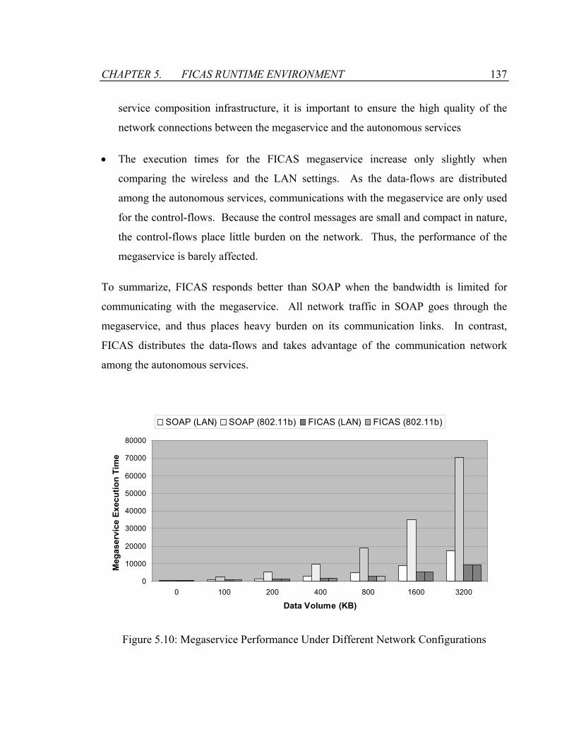
CHAPTER 5. FICAS RUNTIME ENVIRONMENT 137
service composition infrastructure, it is important to ensure the high quality of the
network connections between the megaservice and the autonomous services
• The execution times for the FICAS megaservice increase only slightly when
comparing the wireless and the LAN settings. As the data-flows are distributed
among the autonomous services, communications with the megaservice are only used
for the control-flows. Because the control messages are small and compact in nature,
the control-flows place little burden on the network. Thus, the performance of the
megaservice is barely affected.
To summarize, FICAS responds better than SOAP when the bandwidth is limited for
communicating with the megaservice. All network traffic in SOAP goes through the
megaservice, and thus places heavy burden on its communication links. In contrast,
FICAS distributes the data-flows and takes advantage of the communication network
among the autonomous services.
0
10000
20000
30000
40000
50000
60000
70000
80000
0 100 200 400 800 1600 3200
Data Volume (KB)
Meg
aser
vice
Exe
cutio
n Ti
me
SOAP (LAN) SOAP (802.11b) FICAS (LAN) FICAS (802.11b)
Figure 5.10: Megaservice Performance Under Different Network Configurations

CHAPTER 5. FICAS RUNTIME ENVIRONMENT 138
5.3 Mobile Class and Active Mediation
The mobile class conducts information processing on autonomous services, and
effectively augments the capability of the autonomous services by dynamically adding
functionalities to the services. The use of the mobile class to conduct dynamic
information processing is a form of active mediation. This section describes how active
mediation is supported by the autonomous services and how active mediation facilitates
the performance optimization for megaservices.
5.3.1 Active Mediation for Autonomous Service
Autonomous services are usually built by leveraging existing software applications and
information resources. Mediators are introduced to lower the complexity of software
design and minimize the cost of software maintenance. Mediators [90, 94] are intelligent
middleware that sit between the information sources and the clients of autonomous
services. They provide integrated information, without the need to integrate the actual
information sources. Specifically, mediators perform functions such as accessing and
integrating domain-specific data from heterogeneous sources, restructuring the results
into object-oriented structures, and extracting appropriate information to be transmitted.
Figure 5.11(a) illustrates the mediation architecture, which conceptually consists of three
layers. The information source provides raw data through its source access interface.
The mediation layer resides between the information source and the information client,
incorporating value-added processing by applying domain-specific knowledge
processing. The information client accesses the integrated information via the client
access interface. The architecture of the autonomous service can be mapped to the
mediation architecture, as shown in Figure 5.11(b). The software application resides in
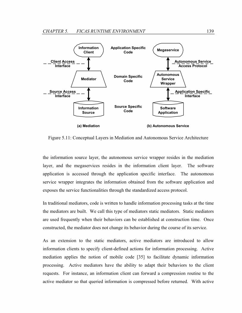
CHAPTER 5. FICAS RUNTIME ENVIRONMENT 139
InformationSource
InformationClient
Application SpecificCode
Domain SpecificCode
Source SpecificCode
Client AccessInterface
Source AccessInterface
Mediator
SoftwareApplication
Megaservice
AutonomousServiceWrapper
(a) Mediation (b) Autonomous Service
Application SpecificInterface
Autonomous ServiceAccess Protocol
Figure 5.11: Conceptual Layers in Mediation and Autonomous Service Architecture
the information source layer, the autonomous service wrapper resides in the mediation
layer, and the megaservices resides in the information client layer. The software
application is accessed through the application specific interface. The autonomous
service wrapper integrates the information obtained from the software application and
exposes the service functionalities through the standardized access protocol.
In traditional mediators, code is written to handle information processing tasks at the time
the mediators are built. We call this type of mediators static mediators. Static mediators
are used frequently when their behaviors can be established at construction time. Once
constructed, the mediator does not change its behavior during the course of its service.
As an extension to the static mediators, active mediators are introduced to allow
information clients to specify client-defined actions for information processing. Active
mediation applies the notion of mobile code [35] to facilitate dynamic information
processing. Active mediators have the ability to adapt their behaviors to the client
requests. For instance, an information client can forward a compression routine to the
active mediator so that queried information is compressed before returned. With active
CHAPTER 5. FICAS RUNTIME ENVIRONMENT 140
mediation, autonomous services can separate service-specific functionalities from client-
specific functionalities, hence providing services as if they were constructed on a per-
client basis. In particular, active mediation provides the following benefits:
• Flexibility of Autonomous Services: An autonomous service is maintained by a
service provider. It is difficult, if not impossible, for the service provider to anticipate
all current and potential information clients, and to provide the clients with
information in a ready-to-use form. Furthermore, there are inevitable delays in
modifying the functionality and the interface of the autonomous service to satisfy the
specific requirements from the clients. The clients therefore need to work around the
differences between the information they require and the information provided by the
autonomous service. The clients usually have to write customized codes (e.g.,
wrappers, filters, etc.) to work around the mismatches. On the other hand, the service
provider generally finds it difficult to alter the existing autonomous service. A
modification for one class of clients can have unexpected effects on other classes of
clients. As the number of clients increases, the service provider becomes more
reluctant to make significant changes to the autonomous service. Active mediation
increases the customizability and flexibility of the autonomous service. Through
active mediation, the client can send dynamic routines to the autonomous service to
expand the functionality of the autonomous service.
• Preserving the power of a compositional language: It is important to have a clear
separation between the compositional specification and the computational
specification in a megaservice. FICAS enforces the separation by completely
removing the computational primitives from its compositional language CLAS. As a
solution, the mobile class is used for computational specification of the megaservice.
Active mediation is supported by the autonomous services in FICAS. The processing
routines specified in the form of mobile classes can therefore be dynamically loaded
and executed on the autonomous services.
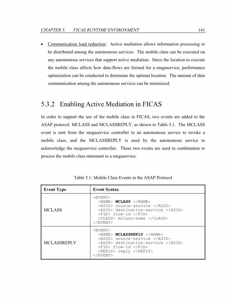
CHAPTER 5. FICAS RUNTIME ENVIRONMENT 141
• Communication load reduction: Active mediation allows information processing to
be distributed among the autonomous services. The mobile class can be executed on
any autonomous services that support active mediation. Since the location to execute
the mobile class affects how data-flows are formed for a megaservice, performance
optimization can be conducted to determine the optimal location. The amount of data
communication among the autonomous services can be minimized.
5.3.2 Enabling Active Mediation in FICAS
In order to support the use of the mobile class in FICAS, two events are added to the
ASAP protocol: MCLASS and MCLASSREPLY, as shown in Table 5.1. The MCLASS
event is sent from the megaservice controller to an autonomous service to invoke a
mobile class, and the MCLASSREPLY is used by the autonomous service to
acknowledge the megaservice controller. These two events are used in combination to
process the mobile class statement in a megaservice.
Table 5.1: Mobile Class Events in the ASAP Protocol
Event Type Event Syntax
MCLASS
<EVENT> <NAME> MCLASS </NAME> <ASID> source-service </ASID> <ASID> destination-service </ASID> <FID> flow-id </FID> <CLASS> mclass-name </CLASS> </EVENT>
MCLASSREPLY
<EVENT> <NAME> MCLASSREPLY </NAME> <ASID> source-service </ASID> <ASID> destination-service </ASID> <FID> flow-id </FID> <REPLY> reply </REPLY> </EVENT>
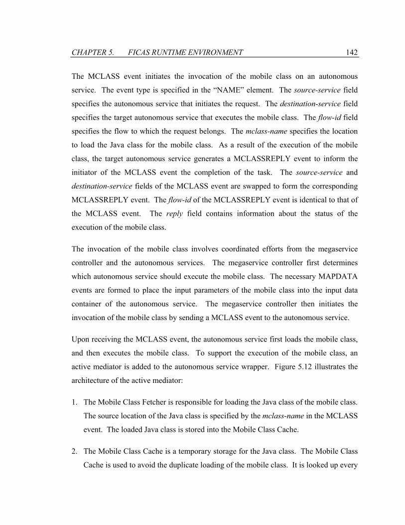
CHAPTER 5. FICAS RUNTIME ENVIRONMENT 142
The MCLASS event initiates the invocation of the mobile class on an autonomous
service. The event type is specified in the “NAME” element. The source-service field
specifies the autonomous service that initiates the request. The destination-service field
specifies the target autonomous service that executes the mobile class. The flow-id field
specifies the flow to which the request belongs. The mclass-name specifies the location
to load the Java class for the mobile class. As a result of the execution of the mobile
class, the target autonomous service generates a MCLASSREPLY event to inform the
initiator of the MCLASS event the completion of the task. The source-service and
destination-service fields of the MCLASS event are swapped to form the corresponding
MCLASSREPLY event. The flow-id of the MCLASSREPLY event is identical to that of
the MCLASS event. The reply field contains information about the status of the
execution of the mobile class.
The invocation of the mobile class involves coordinated efforts from the megaservice
controller and the autonomous services. The megaservice controller first determines
which autonomous service should execute the mobile class. The necessary MAPDATA
events are formed to place the input parameters of the mobile class into the input data
container of the autonomous service. The megaservice controller then initiates the
invocation of the mobile class by sending a MCLASS event to the autonomous service.
Upon receiving the MCLASS event, the autonomous service first loads the mobile class,
and then executes the mobile class. To support the execution of the mobile class, an
active mediator is added to the autonomous service wrapper. Figure 5.12 illustrates the
architecture of the active mediator:
1. The Mobile Class Fetcher is responsible for loading the Java class of the mobile class.
The source location of the Java class is specified by the mclass-name in the MCLASS
event. The loaded Java class is stored into the Mobile Class Cache.
2. The Mobile Class Cache is a temporary storage for the Java class. The Mobile Class
Cache is used to avoid the duplicate loading of the mobile class. It is looked up every
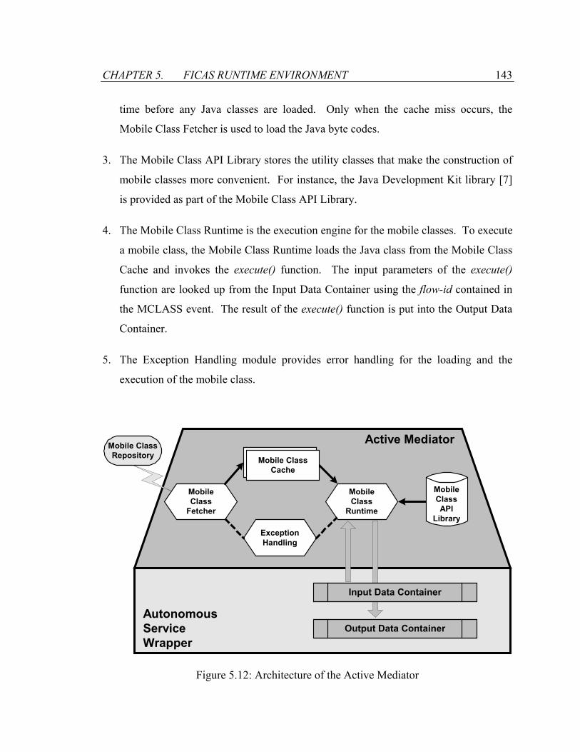
CHAPTER 5. FICAS RUNTIME ENVIRONMENT 143
time before any Java classes are loaded. Only when the cache miss occurs, the
Mobile Class Fetcher is used to load the Java byte codes.
3. The Mobile Class API Library stores the utility classes that make the construction of
mobile classes more convenient. For instance, the Java Development Kit library [7]
is provided as part of the Mobile Class API Library.
4. The Mobile Class Runtime is the execution engine for the mobile classes. To execute
a mobile class, the Mobile Class Runtime loads the Java class from the Mobile Class
Cache and invokes the execute() function. The input parameters of the execute()
function are looked up from the Input Data Container using the flow-id contained in
the MCLASS event. The result of the execute() function is put into the Output Data
Container.
5. The Exception Handling module provides error handling for the loading and the
execution of the mobile class.
AutonomousServiceWrapper
MobileClass
Fetcher
MobileClass
Runtime
ExceptionHandling
Mobile ClassCache
Mobile ClassRepository
Input Data Container
Output Data Container
MobileClassAPI
Library
Active Mediator
Figure 5.12: Architecture of the Active Mediator

CHAPTER 5. FICAS RUNTIME ENVIRONMENT 144
5.3.3 Placement of Mobile Class
The choice of which autonomous service executes the mobile class affects how the data-
flows are formed for the megaservice to which the mobile class belongs. The placement
of the mobile class therefore has significant impact on the performance of the
megaservice. An example megaservice, as shown in Figure 5.13, is used to demonstrate
such impact. The megaservice involves two autonomous services and one mobile class.
The autonomous services, S1 and S2, are the same as the ones in the example illustrated
in Figure 5.8. The mobile class FILTER takes a large string as input, filters through the
content, and returns a string that consists of every 10th character of the input string.
Effectively, the mobile class compresses the content by ten fold. Since the mobile class
can be executed on any one of the autonomous services involved in the megaservice, we
have three potential placement strategies, as shown in Figure 5.14:
• Strategy 1: By placing the mobile class FILTER at the autonomous service that hosts
the megaservice controller, we can construct the execution plan as shown in Figure
5.14(a). S1 generates the data element A and passes it to the megaservice. The
mobile class processes the data element A at the megaservice, and the result B is then
sent to S2 for further processing.
• Strategy 2: By placing the mobile class FILTER at S1, we can construct the execution
plan as shown in Figure 5.14(b). S1 generates the data element A and processes it
locally using the mobile class. The result B is sent from S1 to S2 for further
processing.
• Strategy 3: By placing the mobile class FILTER at S2, we can construct the execution
plan as shown in Figure 5.14(c). S1 generates the data element A and passes it to S2.
S2 processes the data locally using the mobile class and then uses the result B for
further processing.
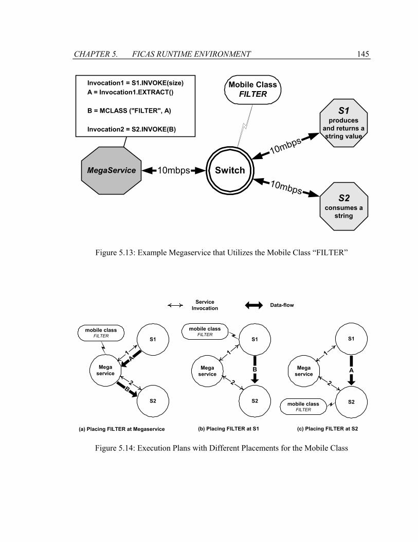
CHAPTER 5. FICAS RUNTIME ENVIRONMENT 145
SwitchMegaService
S1produces
and returns astring value
10mbps
S2consumes a
string
10mbps
Invocation1 = S1.INVOKE(size) A = Invocation1.EXTRACT()
B = MCLASS ("FILTER", A)
Invocation2 = S2.INVOKE(B)
10mbps
Mobile ClassFILTER
Figure 5.13: Example Megaservice that Utilizes the Mobile Class “FILTER”
S1
Megaservice
S2
S1
Megaservice
S2
mobile classFILTER
S1
Megaservice
S2mobile classFILTER
(a) Placing FILTER at Megaservice (b) Placing FILTER at S1 (c) Placing FILTER at S2
1
2
1
2
1
2
Data-flowServiceInvocation
mobile classFILTER
A
B
B A
Figure 5.14: Execution Plans with Different Placements for the Mobile Class
CHAPTER 5. FICAS RUNTIME ENVIRONMENT 146
To compare the strategies, we assume that the performance of loading and executing the
mobile class is the same on all autonomous services. Strategy 1 requires both the input
data element A and the output data element B to be transmitted among the megaservice
and the autonomous services. Thus Strategy 1 incurs the most communication traffic
compared to the other two strategies and has the worst performance. Strategy 2 and
Strategy 3 differ in the data content sent between the autonomous services. For Strategy
2, the data element B is sent from S1 to S2. For Strategy 3, the data element A is sent
from S1 to S2. Since the data element B is one tenth in size compared to the data element
A, Strategy 2 incurs the least amount of communication traffic. Therefore, Strategy 2 is
the placement strategy that has the best performance.
Following the analysis of above example, we derive an algorithm to determine the
optimal placement of the mobile class. The algorithm seeks to locate the autonomous
service that minimizes the data-flows among the autonomous services. Each input data
element of the mobile class is modeled as a pair, (Si, Vi), where Si is the autonomous
service that generates the ith input data element, and Vi is the volume of the data element.
The output data element is modeled as (S0, V0), where S0 is the autonomous service to
which the result of the mobile class will be sent, and V0 is the size of the output data
element. Two observations are made. First, the sum of Vi remains the same regardless
where the mobile class is executed. Second, by placing the mobile class on the
autonomous service Si, we can eliminate the corresponding data-flow volume Vi, since
the data element is local to the autonomous service. Therefore, the optimal placement of
the mobile class is the autonomous service Si that has the largest aggregated Vi.
Figure 5.15 shows the Largest Data Set (LDS) algorithm that selects the autonomous
service that generates and consumes the largest volume of data. The algorithm first
computes the total amount of data associated with each autonomous service. Then, the
autonomous service with the largest data volume is selected. The autonomous service is
returned as the output of the algorithm that represents the optimal placement of the
mobile class.
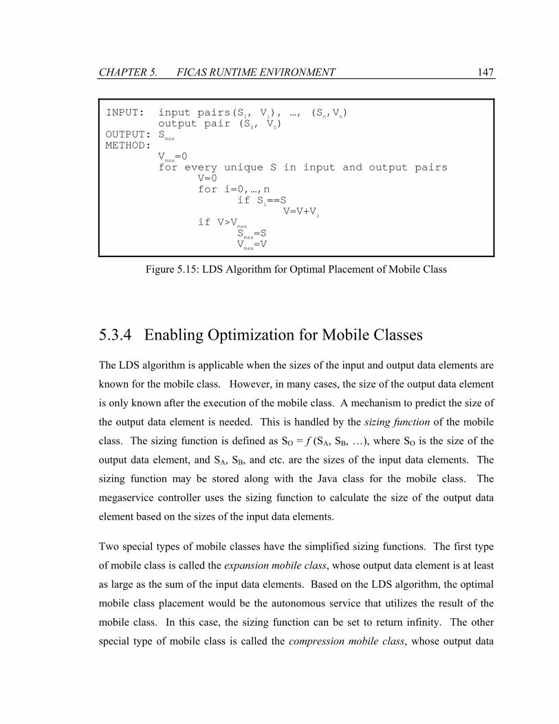
CHAPTER 5. FICAS RUNTIME ENVIRONMENT 147
INPUT: input pairs(S1, V1), …, (Sn,Vn) output pair (S0, V0) OUTPUT: Smax METHOD: Vmax=0 for every unique S in input and output pairs V=0 for i=0,…,n if Si==S V=V+Vi if V>Vmax Smax=S Vmax=V
Figure 5.15: LDS Algorithm for Optimal Placement of Mobile Class
5.3.4 Enabling Optimization for Mobile Classes
The LDS algorithm is applicable when the sizes of the input and output data elements are
known for the mobile class. However, in many cases, the size of the output data element
is only known after the execution of the mobile class. A mechanism to predict the size of
the output data element is needed. This is handled by the sizing function of the mobile
class. The sizing function is defined as SO = f (SA, SB, …), where SO is the size of the
output data element, and SA, SB, and etc. are the sizes of the input data elements. The
sizing function may be stored along with the Java class for the mobile class. The
megaservice controller uses the sizing function to calculate the size of the output data
element based on the sizes of the input data elements.
Two special types of mobile classes have the simplified sizing functions. The first type
of mobile class is called the expansion mobile class, whose output data element is at least
as large as the sum of the input data elements. Based on the LDS algorithm, the optimal
mobile class placement would be the autonomous service that utilizes the result of the
mobile class. In this case, the sizing function can be set to return infinity. The other
special type of mobile class is called the compression mobile class, whose output data

CHAPTER 5. FICAS RUNTIME ENVIRONMENT 148
element is smaller than at least one of the input data elements. The optimal mobile class
placement is one of the autonomous services that generate the input data elements. In
this case, the sizing function can be set to return zero.
The effectiveness of the LDS algorithm depends on the accuracy of the sizing function.
We demonstrate through examples how the sizing function may be obtained. The
relational mobile classes (as defined in Section 4.3.2) are used, because the relationships
between the sizes of their input and output data elements are well defined [49]. The
sizing functions, as shown in Table 5.2, can be formulated in the following manner:
• The unary operators select and project return portions of the input relations. The
mobile classes implementing the operators are by definition the compression mobile
class. Hence, their sizing functions return zero.
• The union operator combines the two input relations. The mobile class is an
expansion mobile class. Hence, the sizing function returns infinity.
• The intersect and difference operators return portions of the input relations. Their
mobile classes are therefore compression mobile classes, and the sizing functions
return zero.
• The result set of cartesian product operator contains all possible combinations of one
tuple from each input relations. The result relation is much larger than the input
relations. Hence, the sizing function returns infinity.
• The sizing function for the join operator is more complex. The sizing function
depends on the characteristics of the input data and the predicate condition. For
instance, if the join is an equality join with uniformly distributed values in input
relations, the sizing function may be set to S0=c×SA×SB, where c is the selection
factor of the join. If the result relation is expected to be rather small, the sizing
function can be set to zero to let the LDS algorithm choose one of the autonomous
services that generate the input data elements. If the result relation is expected to be
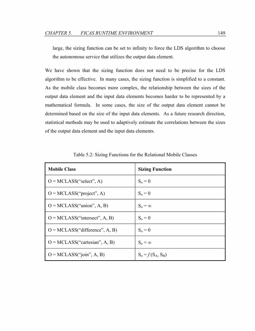
CHAPTER 5. FICAS RUNTIME ENVIRONMENT 149
large, the sizing function can be set to infinity to force the LDS algorithm to choose
the autonomous service that utilizes the output data element.
We have shown that the sizing function does not need to be precise for the LDS
algorithm to be effective. In many cases, the sizing function is simplified to a constant.
As the mobile class becomes more complex, the relationship between the sizes of the
output data element and the input data elements becomes harder to be represented by a
mathematical formula. In some cases, the size of the output data element cannot be
determined based on the size of the input data elements. As a future research direction,
statistical methods may be used to adaptively estimate the correlations between the sizes
of the output data element and the input data elements.
Table 5.2: Sizing Functions for the Relational Mobile Classes
Mobile Class Sizing Function
O = MCLASS(“select”, A) So = 0
O = MCLASS(“project”, A) So = 0
O = MCLASS(“union”, A, B) So = ∞
O = MCLASS(“intersect”, A, B) So = 0
O = MCLASS(“difference”, A, B) So = 0
O = MCLASS(“cartesian”, A, B) So = ∞
O = MCLASS(“join”, A, B) So = f (SA, SB)
CHAPTER 5. FICAS RUNTIME ENVIRONMENT 150
5.3.5 Performance Analysis
We analyze the performance of the megaservice previously defined in Figure 5.13. The
megaservice is executed using different placements of the mobile class FILTER. We
intend to measure the impact of the placement of the mobile class on the performance of
the megaservice. In addition, we replace the mobile class FILTER with an autonomous
service that implements the same functionality. The performance of the megaservice
utilizing the autonomous service is measured and compared with the megaservice
utilizing the mobile class. Overall, three scenarios are considered:
1. Strategy 1: The megaservice conducts active mediation on S1 by executing the
mobile class FILTER on S1. The placement of the mobile class is generated by the
LDS algorithm.
2. Strategy 2: The megaservice conducts active mediation on S2 by executing the
mobile class FILTER on S2.
3. Strategy 3: We implement a utility autonomous service that replaces the mobile class
FILTER. The string generated by S1 is fed into the autonomous service, and the
result is forwarded onto S2 for further processing.
Figure 5.16 shows the execution times of the megaservice. Different settings on the size
of the string generated by S1 are used. The following observations are made:
• The execution times of the megaservices increase with the size of the string. Three
factors contribute to the increased execution times. First, longer time is taken to
measure the size of the string. It results in the longer execution time for the LDS
algorithm. Second, it takes longer to execute the mobile class or the utility
autonomous service. Third, the larger string results in longer transmission time for
the data elements.

CHAPTER 5. FICAS RUNTIME ENVIRONMENT 151
0
2000
4000
6000
8000
10000
12000
100 200 400 800 1600 3200
Data Volume (KB)
Meg
aser
vice
Exe
cutio
n Ti
me
Mobile Class on S1 Mobile Class on S2 Utility Autonomous Service
Figure 5.16: Comparison Between Mobile Class and Autonomous Service
• The placement of the mobile class significantly impacts the performance of the
megaservice. Strategy 1 performs significantly better than Strategy 2. Strategy 1
utilizes the LDS algorithm to minimize the amount of data-flows incurred by the
megaservice. In Strategy 2, S1 transmits the original string to S2. Whereas in
Strategy 1, S1 only transmits the filtered string to S2. Strategy 1 causes significantly
less amount of data traffic than Strategy 2.
• Both strategies involving the mobile class perform better than Strategy 3, which uses
the utility autonomous service. Strategy 3 incurs the most amount of data-flows, as
both the original string and the filtered string are transmitted among the autonomous
services. In addition, the invocation of the autonomous service is more costly than
the invocation of the mobile class.
In summary, active mediation enabled by the mobile class is an effective approach in
improving the performance of the megaservice. The mobile class can be placed onto the
appropriate autonomous service to minimize the amount of data communications.
CHAPTER 5. FICAS RUNTIME ENVIRONMENT 152
5.4 Example Infrastructure for Engineering Services
We have shown through simple examples that FICAS is well suited for composing the
autonomous services that exchange large volumes of data. The distribution of the data-
flows and the use of the mobile class facilitate service composition and improve the
performance of the megaservice. To demonstrate the effectiveness of FICAS, we
implement an engineering service infrastructure for construction project management
applications. We illustrate the process of building the service infrastructure: (1)
wrapping software applications into autonomous services, (2) implementing mobile
classes, and (3) constructing megaservices to accomplish the engineering tasks.
The first step in building the engineering service infrastructure is to wrap each software
application into an autonomous service. We create the service core of the autonomous
service by defining the ServiceCore interface based on the software application. The
service core is then linked to an autonomous service wrapper (ASW), as described in
Section 3.3. Figure 5.17 shows an example of wrapping the Primavera P3 application
into an autonomous service that supports project scheduling. The P3Service class
implements the ServiceCore interface and defines the three methods that connect the
application to the autonomous service wrapper. The setup() method and the terminate()
method specify that no action is performed for the initialization and the termination of the
autonomous service. The execute() method defines the actions for the invocation of the
autonomous service. The method starts by fetching the input parameters from the input
data container. The first parameter specifies the service request, and the second
parameter contains the input data for a schedule, based on which the Primavera P3™
application is utilized to conduct scheduling. The result of the scheduling is encapsulated
into a data element and put into the output data container. Data encapsulation utilizes the
Process Specification Language (PSL) format [83] as the common data exchange model
so that multiple services can interoperate. The P3Service class is provided as an input to

CHAPTER 5. FICAS RUNTIME ENVIRONMENT 153
the constructor of the ASW class to connect the Primavera P3 application with the
autonomous service wrapper. After the autonomous service is built, it is registered with
the autonomous service directory. The registration entry specifies the name, the IP
address, and the TCP/IP port of the autonomous service. Once registered, the
autonomous service is ready to be used for composition.
Lightweight information processing routines are specified as mobile classes. Figure 5.18
shows the mobile class that converts data from the PSL format into the Microsoft Excel
format. The psltoexcel class implements the MobileClass interface, as described in
Section 4.3.1. The execute() function takes the first argument for the mobile class as the
input data, converts the data into the Excel format, and returns the converted data as the
output data element. The psltoexcel class is compiled into a Java class, which is put into
the mobile class repository, http://ficas.stanford.edu/mcrepo, as shown on the first line in
Figure 5.19.
Figure 5.19 shows an example megaservice that utilizes multiple autonomous services
and mobile classes to perform rescheduling of project plans. The megaservice is
specified in the CLAS language, as described in Section 4.1. Three autonomous services
are utilized by the megaservice: (1) the PSLService that handles the access of the project
models, (2) the P3Service that conducts the scheduling of a project plan, and (3) the
ExcelService that displays the project plan. The invocation of the megaservice causes the
PSLService to fetch the project model, which is then rescheduled by the P3Service. The
updated schedule is stored back to the database using the PSLService and shown to the
project personnel using the ExcelService. The mobile class psltoexcel is used to perform
data conversion between PSLService and ExcelService. The CLAS program is compiled
into a control sequence by the CLAS compiler, as described in Section 4.2. The control
sequence is then placed in a repository that is accessible to the runtime environment of
FICAS. For instance, the control sequence may be accessed on the web at
“http://ficas.stanford.edu/Megaprogram/SchedulingDemo.xml”.
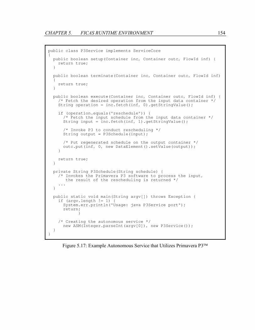
CHAPTER 5. FICAS RUNTIME ENVIRONMENT 154
public class P3Service implements ServiceCore public boolean setup(Container inc, Container outc, FlowId inf) return true; public boolean terminate(Container inc, Container outc, FlowId inf) return true; public boolean execute(Container inc, Container outc, FlowId inf) /* Fetch the desired operation from the input data container */ String operation = inc.fetch(inf, 0).getStringValue(); if (operation.equals("reschedule")) /* Fetch the input schedule from the input data container */ String input = inc.fetch(inf, 1).getStringValue(); /* Invoke P3 to conduct rescheduling */ String output = P3Schedule(input); /* Put regenerated schedule on the output container */ outc.put(inf, 0, new DataElement().setValue(output)); return true; private String P3Schedule(String schedule) /* Invokes the Primavera P3 software to process the input, the result of the rescheduling is returned */ ... public static void main(String argv[]) throws Exception if (argv.length != 1) System.err.println("Usage: java P3Service port"); return; /* Creating the autonomous service */ new ASM(Integer.parseInt(argv[0]), new P3Service());
Figure 5.17: Example Autonomous Service that Utilizes Primavera P3
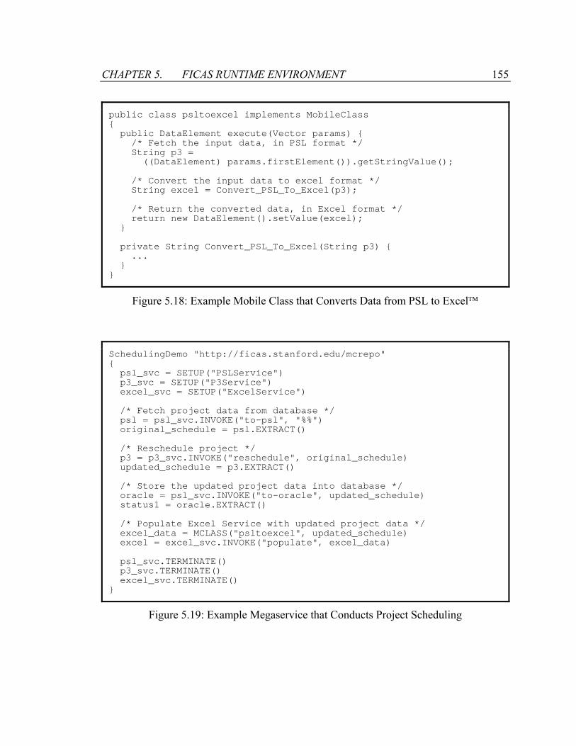
CHAPTER 5. FICAS RUNTIME ENVIRONMENT 155
public class psltoexcel implements MobileClass public DataElement execute(Vector params) /* Fetch the input data, in PSL format */ String p3 = ((DataElement) params.firstElement()).getStringValue(); /* Convert the input data to excel format */ String excel = Convert_PSL_To_Excel(p3); /* Return the converted data, in Excel format */ return new DataElement().setValue(excel); private String Convert_PSL_To_Excel(String p3) ...
Figure 5.18: Example Mobile Class that Converts Data from PSL to Excel
SchedulingDemo "http://ficas.stanford.edu/mcrepo" psl_svc = SETUP("PSLService") p3_svc = SETUP("P3Service") excel_svc = SETUP("ExcelService") /* Fetch project data from database */ psl = psl_svc.INVOKE("to-psl", "%%") original_schedule = psl.EXTRACT() /* Reschedule project */ p3 = p3_svc.INVOKE("reschedule", original_schedule) updated_schedule = p3.EXTRACT() /* Store the updated project data into database */ oracle = psl_svc.INVOKE("to-oracle", updated_schedule) status1 = oracle.EXTRACT() /* Populate Excel Service with updated project data */ excel_data = MCLASS("psltoexcel", updated_schedule) excel = excel_svc.INVOKE("populate", excel_data) psl_svc.TERMINATE() p3_svc.TERMINATE() excel_svc.TERMINATE()
Figure 5.19: Example Megaservice that Conducts Project Scheduling
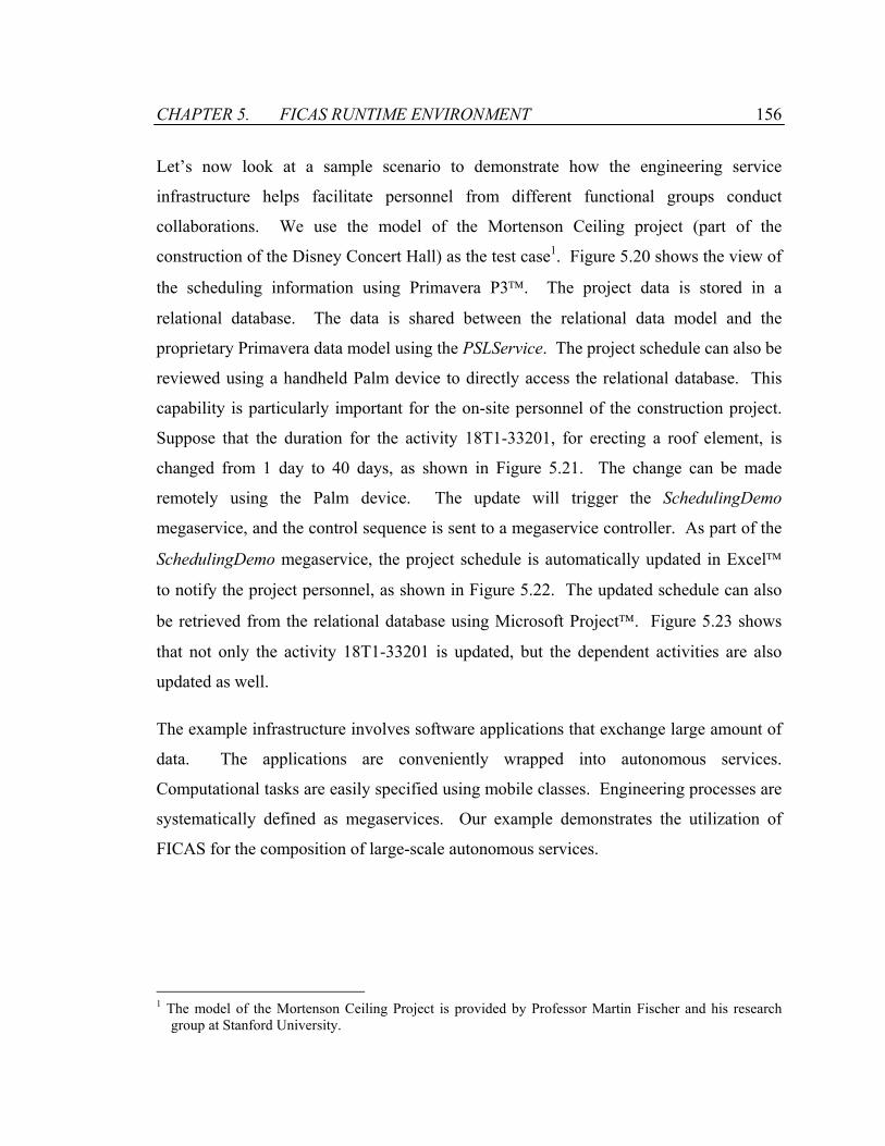
CHAPTER 5. FICAS RUNTIME ENVIRONMENT 156
Let’s now look at a sample scenario to demonstrate how the engineering service
infrastructure helps facilitate personnel from different functional groups conduct
collaborations. We use the model of the Mortenson Ceiling project (part of the
construction of the Disney Concert Hall) as the test case1. Figure 5.20 shows the view of
the scheduling information using Primavera P3. The project data is stored in a
relational database. The data is shared between the relational data model and the
proprietary Primavera data model using the PSLService. The project schedule can also be
reviewed using a handheld Palm device to directly access the relational database. This
capability is particularly important for the on-site personnel of the construction project.
Suppose that the duration for the activity 18T1-33201, for erecting a roof element, is
changed from 1 day to 40 days, as shown in Figure 5.21. The change can be made
remotely using the Palm device. The update will trigger the SchedulingDemo
megaservice, and the control sequence is sent to a megaservice controller. As part of the
SchedulingDemo megaservice, the project schedule is automatically updated in Excel
to notify the project personnel, as shown in Figure 5.22. The updated schedule can also
be retrieved from the relational database using Microsoft Project. Figure 5.23 shows
that not only the activity 18T1-33201 is updated, but the dependent activities are also
updated as well.
The example infrastructure involves software applications that exchange large amount of
data. The applications are conveniently wrapped into autonomous services.
Computational tasks are easily specified using mobile classes. Engineering processes are
systematically defined as megaservices. Our example demonstrates the utilization of
FICAS for the composition of large-scale autonomous services.
1 The model of the Mortenson Ceiling Project is provided by Professor Martin Fischer and his research
group at Stanford University.
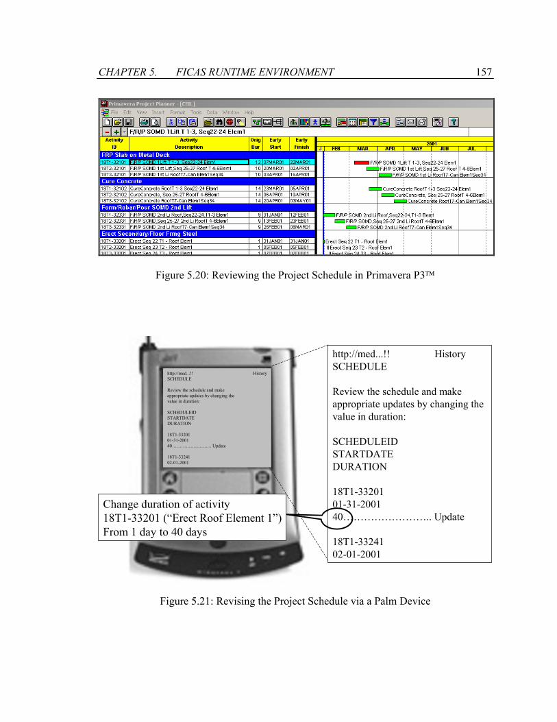
CHAPTER 5. FICAS RUNTIME ENVIRONMENT 157
Figure 5.20: Reviewing the Project Schedule in Primavera P3
http://med...!! HistorySCHEDULE
Review the schedule and make appropriate updates by changing thevalue in duration:
SCHEDULEIDSTARTDATEDURATION
18T1-3320101-31-2001 40…………………….. Update
18T1-3324102-01-2001
http://med...!! HistorySCHEDULE
Review the schedule and make appropriate updates by changing thevalue in duration:
SCHEDULEIDSTARTDATEDURATION
18T1-3320101-31-2001 40…………………….. Update
18T1-3324102-01-2001
Change duration of activity18T1-33201 (“Erect Roof Element 1”)From 1 day to 40 days
Figure 5.21: Revising the Project Schedule via a Palm Device
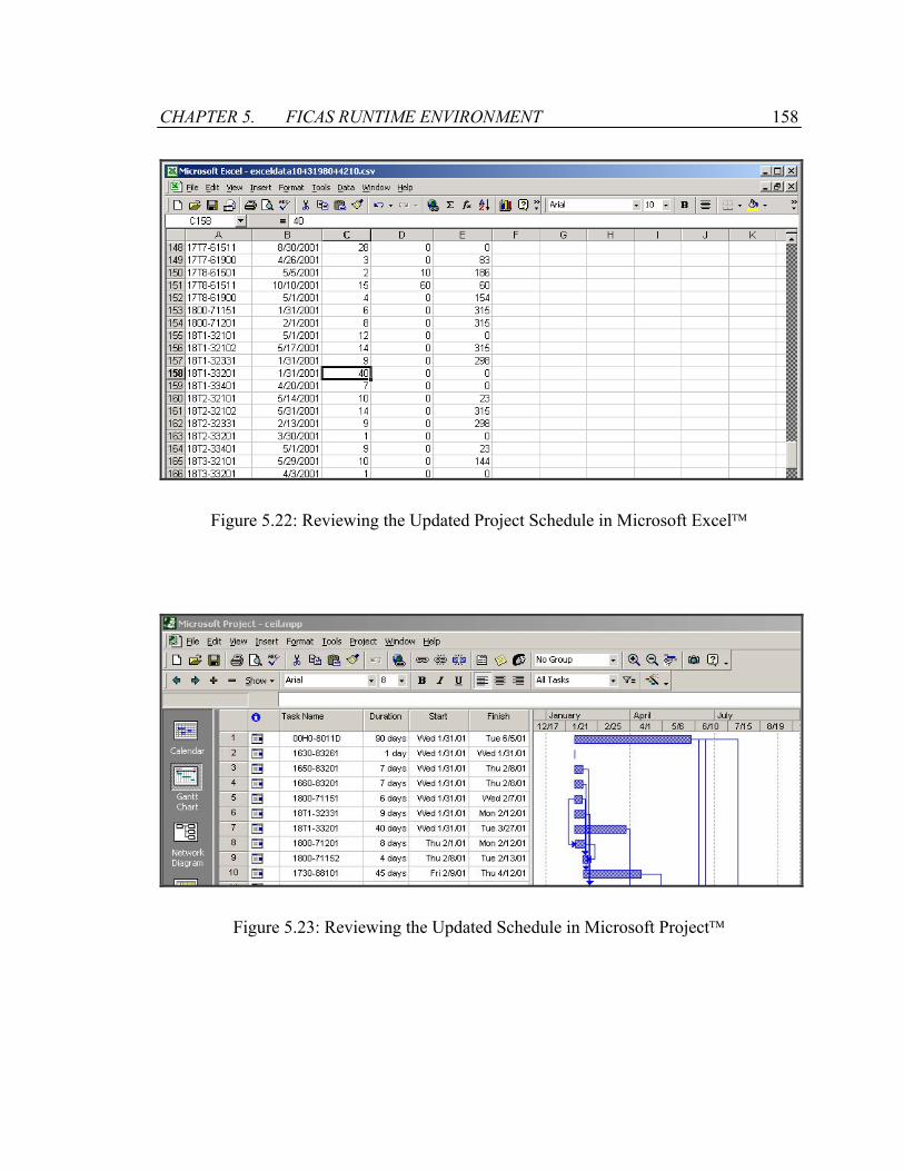
CHAPTER 5. FICAS RUNTIME ENVIRONMENT 158
Figure 5.22: Reviewing the Updated Project Schedule in Microsoft Excel
Figure 5.23: Reviewing the Updated Schedule in Microsoft Project
CHAPTER 5. FICAS RUNTIME ENVIRONMENT 159
5.5 Summary
This chapter describes the runtime environment of FICAS that handles the execution of
megaservices. The runtime environment ties together autonomous services with a
communication network. A directory is used to keep track of the autonomous services.
The directory is kept up to date where an autonomous service can join and leave the
runtime environment by simply updating its status with the directory. A large number of
autonomous services can be incorporated into the runtime environment using this self-
maintenance model.
The megaservice controller is the part of the autonomous service that handles the
execution of the megaservice. It shares with the autonomous service wrapper the data
containers and the event queues for exchanging data and events with other autonomous
services. The megaservice controller interprets the control sequence generated by the
buildtime environment of FICAS to form an execution plan. The execution plan defines
the set of ASAP events and the dependencies among the events that are used to
coordinate the autonomous services that make up the megaservice.
The runtime environment of FICAS supports the distribution of the data-flows for the
execution of the megaservice. The autonomous services are coordinated by the
centralized controller, while the services can exchange data directly among themselves.
To measure the impact of the distribution of the data-flows on the performance of the
megaservice, we compare FICAS with Apache SOAP. The megaservice implemented in
SOAP incurs the centralized data-flows among the autonomous services. We observe
that FICAS outperforms SOAP significantly when the volume of the data communication
among the autonomous services is high. In addition, FICAS is less affected than SOAP
when the quality of the access links between the megaservice and the autonomous
services degrades.

CHAPTER 5. FICAS RUNTIME ENVIRONMENT 160
The ability to conduct dynamic information processing on the autonomous service is
called active mediation. The active mediator is incorporated into the autonomous service
that would allow mobile classes to be executed on the autonomous service. Active
mediation provides three benefits to the service composition infrastructure. First, active
mediation increases the customizability of an autonomous service. A client can send a
mobile class to an autonomous service to expand the functionality of the autonomous
service. Second, the computational specification can be separated from the
compositional specification of the megaservice. The compositional specification is
handled by the megaservice controller, while the computational specification is executed
by the active mediator. Third, since the mobile class can be executed on any autonomous
service that supports active mediation, performance optimization can be performed. In
many situations, we have shown that using the mobile class is more efficient than using
the autonomous service to conducting computational processing. The mobile class can
be utilized to minimize the data-flows involved in the megaservice.
Based on FICAS, an example service infrastructure is constructed for project
management applications in the construction industry. The applications are conveniently
wrapped into autonomous services. An integrated work process that conducts project
scheduling is specified as a megaservice using the CLAS language. To perform the
scheduling of a construction project, large volumes of data are exchanged among the
autonomous service. The example infrastructure demonstrates that the distributed data-
flow model is suitable for composing large-scale software services.

Chapter 6
Summary and Future Directions
6.1 Summary
This thesis studies in details the software engineering technology for distributed service
composition. First, a distributed data-flow model for composing software services has
been introduced. The model allows data to be interchanged among the services,
bypassing a central hub for data communications. The model has been compared with
the centralized data-flow model, and the pros and cons of the models are analyzed.
Second, we have implemented a prototype infrastructure for service composition based
on the distributed data-flow model. The infrastructure includes a service wrapper, a
composition language, a buildtime environment and a runtime environment. Various
phases of service composition are examined to understand how the distributed data-flow
model can be supported. Third, we have demonstrated the effectiveness of the distributed
data-flow model by applying the infrastructure for the integration of distributed
engineering services. This section offers a brief discussion on the contributions.

CHAPTER 6. SUMMARY AND FUTURE DIRECTIONS 162
This thesis has developed a distributed data-flow model for composing autonomous
software services. Under our software composition paradigm, such services are managed
by independent providers, and are linked to form a data processing system controlled by a
megaservice. The development of the distributed data-flow model is motivated by the
need to integrate large-scale services on the web. We can find a motivating example in
an Internet environment where services are connected by a fast and high bandwidth
network, and a mobile client accesses the services via slow wireless connections. By
using the distributed data-flow model, a megaservice can be executed on the mobile
client. The distributed data-flow model uses the mobile client as the central controller,
while allowing data to be directly exchanged among the services.
The distributed data-flow model differs from the traditional centralized data-flow model,
where a megaservice acts as the central node for interactions with autonomous services.
In the distributed data-flow model, the megaservice no longer serves as the central hub
for data exchanges among the services. Theoretical analysis is conducted to compare the
performance of the centralized and the distributed data-flow models. Performance
metrics are defined for the various components within a service integration environment.
The analysis concludes that the distributed data-flow model in most situations performs
better than the centralized data-flow model. Furthermore, the analysis identifies system
bottlenecks for both models. For the centralized data-flow model, the access links
connecting the megaservice to the autonomous service are critical resources and should
be optimized for better performance. For the distributed data-flow model, the network
among the services should be the focus when building a service integration environment.
A service composition infrastructure, FICAS, is developed as a prototype implementation
based on the distributed data-flow model. FICAS is a collection of software modules that
support the construction of autonomous services, facilitate the specification of the
megaservice, and enable the efficient execution of the megaservice. FICAS is used to
verify the findings from the theoretical analysis, and to serve as a test bed to investigate
how the distributed data-flow model can be supported for service composition.
CHAPTER 6. SUMMARY AND FUTURE DIRECTIONS 163
For constructing autonomous services, a metamodel is defined to describe the
hierarchical composition of the services, the data model for exchanging information
among the services, the internal structure of the services, and the external interface for
interacting with the services. The metamodel allows the services to be constructed
independently in a homogeneous manner, hence enabling the integration of the services
in a heterogeneous computing environment. The key feature of the metamodel is the
explicit separation of the data-flows from the control-flows for an autonomous service.
Services conforming to the metamodel can be coordinated by a centralized controller,
while data exchange can be distributed among the services. The metamodel is
implemented in the form of the ASAP protocol and an autonomous service wrapper. The
ASAP protocol defines the standard interface for interacting with the autonomous
services as a set of XML messages. The autonomous service wrapper incorporates the
common components of the service, such as the data containers, the event queues, the
support for the ASAP protocol, etc. The wrapper for an autonomous service requires
only three functions, which define the actions taken by the encapsulated software
application for the initialization, invocation, and termination of the service. Together, the
metamodel, the ASAP protocol, and the autonomous service wrapper provide a scalable
framework for constructing autonomous services that supports the distributed data-flow
model.
For specifying megaservices, the CLAS language is introduced as the high-level
compositional language in FICAS. CLAS is designed to be a purely compositional
language whose users possess little programming expertise. It has a limited set of control
constructs and supports a restricted set of data types. CLAS breaks up the traditional
remote procedure call into several statements, so that asynchronicity can be obtained at
the runtime to allow parallel invocations of a service. Using CLAS, a megaprogrammer
can focus on the composition of functionalities, and leaves performance optimization to
the runtime environments of FICAS.
CHAPTER 6. SUMMARY AND FUTURE DIRECTIONS 164
Data transformations and similar computational tasks are often needed to interface
autonomous services. Since in the distributed data-flow model the data communications
bypass the megaservice, such transformations have to be carried out externally. To
achieve that we define mobile classes, dynamic processing routines that can be loaded
onto an autonomous service to prepare data local to the service. The mobile class
supports a wide range of computational functionalities. The use of a general
programming language, i.e., Java, provides a megaprogrammer the flexibility in
specifying computational functionalities. Furthermore, the mobile class gives the runtime
environment the opportunity to conduct performance optimization. The mobile class
allows computation to be relocated to where data is, rather than transferring the data to
where the computation is defined.
The execution of a megaservice is coordinated by a central controller. An execution plan
is generated for a megaservice to select, schedule and sequence the control messages sent
by the controller. Two approaches are explored. First, data dependencies are extracted
from a megaservice, and direct data exchanges among the autonomous services are
formed. Performance tests are conducted to show that the distribution of data
communications improves megaservice performance, especially when large volumes of
data are exchanged among the services. The distributed data-flow model also eliminates
the bottleneck on the communication links of the megaservice by taking advantage of the
communication network among the services. Second, the mobile class and the
distribution of data allow client specific computations to occur remotely on the
autonomous services. By moving computations to where data is located, a megaservice
can significantly reduce the amount of data communication traffic. Performance
optimization is conducted by selecting the most appropriate location to execute the
mobile class. Tests have shown that the mobile class is an effective approach in
improving megaservice performance. In many situations, mobile classes are more
efficient than autonomous services to perform computations.
CHAPTER 6. SUMMARY AND FUTURE DIRECTIONS 165
To demonstrate the effectiveness of FICAS, an example engineering service
infrastructure was built for construction project management applications, which
exchange large volumes of data. The software applications are conveniently wrapped
into autonomous services. Computational tasks are easily specified using mobile classes.
Engineering processes are systematically defined as megaservices. The example
demonstrates that FICAS, utilizing a distributed data-flow model, is suitable for the
composition of large-scale autonomous services.
6.2 Future Directions
This research has focused on the performance issues encountered in composed services.
The principal objective of FICAS has been to serve as a test vehicle for developing and
investigating the distributed data-flow model. FICAS is not a product ready for
widespread use. All of the components in FICAS are implemented in Java, and little
effort has been devoted to computational efficiency. Additional research and
development are needed to further enhance the robustness and efficiency of FICAS. To
make a production version of FICAS, C or C++ can be used as the implementation
language. Furthermore, mobile classes are currently represented as Java byte codes.
Being interpretive in nature, Java is less efficient than assembly or machine codes. The
active mediator can be improved to support dynamic loading of other object codes to
improve the performance of mobile classes.
Besides performance, a number of other important issues need to be considered for
service composition. First, failure management of autonomous services and
megaservices needs to be addressed. FICAS is designed under the assumption that
services are unlikely to fail. Minimal support for failure handling is built into FICAS.
Although the modularity of the services provides good isolation and tractability for
failures, FICAS does not provide any systematic mechanism for failure recovery. When

CHAPTER 6. SUMMARY AND FUTURE DIRECTIONS 166
a megaservice fails, the involved services are restarted or rolled back in an ad hoc
fashion. This approach becomes infeasible when the number of services scales up. For
FICAS to be widely adopted, a new approach to quickly identify and recover from
failures is needed. A starting point would be to investigate the failure management
technologies for business transactions and computer systems [3, 52, 72]. These
technologies can be enhanced for service composition. For FICAS, new techniques will
be required since data and computations are distributed among services.
Another area of improvement can be achieved in further reducing the complexity of
composing services. FICAS provides a framework that allows people with minimal
programming expertise to compose software services. Under the current implementation,
megaservices are specified as text-based programs in FICAS. As an extension, a
graphical user interface (GUI) can be created to integrate the specification, compilation,
and execution of megaservices. Megaservices can still be stored as text-based programs,
and the GUI would serve as a proxy that invokes the current set of tools designed for the
text-based programs.
Furthermore, it is important for decision makers to build applications that incorporate the
results of simulations as well as other software components. As a future extension,
SimQL can be integrated with FICAS to provide megaprogrammers an interface for
accessing information about future events [93, 95]. As a result, the megaprogrammers
can plan and schedule actions beyond the current point in time.
Finally, service composition is only possible when services can exchange information
despite the differences in how their data is represented. Evolving technologies, such as
the Semantic Web [11, 44], can be used to improve communications and interoperability
among entities using differing terminologies. Continued advances in the data integration
technology are essential for the wide adoption of the service composition paradigm.

Bibliography
[1] R. M. Adler. "Distributed Coordination Models for Client-Server Computing,"
IEEE Computer, vol. 28(4), pp. 14-22, April 1995.
[2] S. Ahuja, N. Carriero, and D. Gelernter. "Linda and Friends," IEEE Computer, vol.
19(8), pp. 26-34, August 1986.
[3] G. Alonso, M. Kamath, D. Agrawal, A. El-Abbadi, R. Gunthor, and C. Mohan.
Failure Handling in Large Scale Workflow Management Systems, IBM Almaden
Research Center, San Jose, CA, Report # RJ 9913, November 1994.
[4] Apache SOAP, Apache Software Foundation, http://xml.apache.org/soap/, 2002.
[5] N. Apte and T. Mehta. UDDI: Building Registry-based Web Services Solutions,
Pearson Education, 2003.
[6] F. Arbab, I. Herman, and P. Spilling. "An Overview of Manifold and its
Implementation," Concurrency: Practice and Experience, vol. 5(1), pp. 23-70, Feb
1993.
[7] K. Arnold, J. Gosling, and D. Holmes. The Java Programming Language, Java
Series, Boston, MA, Addison-Wesley, 2000.
[8] H. Bal and M. Haines. "Approaches for Integrating Task and Data Parallelism,"
IEEE Concurrency, vol. 6(3), pp. 74-84, July 1998.
BIBLIOGRAPHY 168
[9] D. Beringer, C. Tornabene, P. Jain, and G. Wiederhold. "A Language and System
for Composing Autonomous, Heterogeneous and Distributed Megamodules,"
Proceedings of DEXA International Workshop on Large-Scale Software
Composition, Vienna Austria, August 1998.
[10] F. Berman. "High-performance schedulers," in The Grid: Blueprint for a New
Computing Infrastructure, I. Foster and C. Kesselman (eds.), Morgan Kaufmann
Publishers, 1998.
[11] T. Berners-Lee, J. Hendler, and O. Lassila. "The Semantic Web," Scientific
American, vol. 284(5), pp. 34-43, May 2001.
[12] A. D. Birrell and B. J. Nelson. "Implementing remote procedure calls," ACM
Transactions on Computer Systems, vol. 2(1), pp. 39-59, February 1984.
[13] S. Bodoff, D. Green, K. Haase, E. Jendrock, M. Pawlan, and B. Stearns. The J2EE
Tutorial, Addison Wesley Professional, 2002.
[14] B. Boehm and B. Scherlis. "Megaprogramming," Proceedings of DARPA Software
Technology Conference, Los Angeles, pp. 68-82, April 1992.
[15] D. Box, D. Ehnebuske, G. Kakivaya, A. Layman, N. Mendelsohn, H. Nielsen, S.
Thatte, and D. Winer. Simple Object Access Protocol (SOAP), W3C Note,
http://www.w3.org/TR/SOAP, 2000.
[16] N. Carriero and D. Gelernter. "The S/Net Linda Kernel," ACM Transactions on
Computer Systems, vol. 4(2), pp. 110-129, May 1986.
[17] N. Carriero and D. Gelernter. "Linda in Context," ACM Communications, vol.
32(4), pp. 444-458, April 1989.
BIBLIOGRAPHY 169
[18] S. Chandrasekaran, S. Madden, and M. Ionescu. Ninja Paths: An Architecture for
Composing Services over Wide Area Networks, UC Berkeley, Technical Report,
http://ninja.cs.berkeley.edu/dist/papers/path.ps.gz, 2000.
[19] S. Chawathe, H. Garcia-Molina, J. Hammer, K. Ireland, Y. Papakonstantinou, J.
Ullman, and J. Widom. "The TSIMMIS Project: Integration of Heterogeneous
Information Sources," Proceedings of 10th Meeting of the Information Processing
Soc. of Japan, pp. 7-18, 1994.
[20] S. S. Chawathe. "Describing and Manipulating XML Data," Bulletin of the IEEE
Technical Committee on Data Engineering, vol. 22(3), pp. 3-9, 1999.
[21] J. Cheng and K. H. Law. "Using Process Specification Language for Project
Information Exchange," Proceedings of 3rd International Conference on
Concurrent Engineering in Construction, Berkeley, CA, pp. 63-74, 2002.
[22] D. Chess, B. Grosof, C. Harrison, D. Levine, C. Parris, and G. Tsudik. "Itinerant
Agents for Mobile Computing," IEEE Personal Communications, vol. 2(5), pp.
34-49, October 1995.
[23] E. Christensen, F. Curbera, G. Meredith, and S. Weerawarana. WSDL. Web
Services Description Language, W3C Note, http://www.w3.org/TR/wsdl, 2000.
[24] S. Cluet, C. Delobel, J. Simeon, and K. Smaga. "Your Mediators Need Data
Conversion!," Proceedings of ACM SIGMOD International Conference on
Management of Data, Seattle, Washington, pp. 177-188, June 1998.
[25] G. F. Colouris and J. Dollimore. Distributed Systems: Concepts and Design,
Addison Wesley, 1988.
[26] D. E. Comer. Internetworking with TCP/IP, Volume I, Principles, Protocols, and
Architecture, 4th ed, Prentice Hall, 2000.
BIBLIOGRAPHY 170
[27] F. Cristian. "A Rigorous Approach to Fault-tolerant Programming," IEEE
Transaction on Software Engineering, vol. 11(1), 1985.
[28] F. Cristian. "Understanding Fault-tolerant Distributed Systems," Communications
of the ACM, vol. 34(2), pp. 56-78, 1991.
[29] D. Davis and M. Parashar. "Latency Performance of SOAP Implementations,"
Proceedings of 2nd IEEE/ACM International Symposium on Cluster Computing
and the Grid (CCGrid2002), Berlin, Germany, pp. 407-412, May 2002.
[30] J. B. Dennis and G. R. Gao. "An Efficient Pipelined Dataflow Processor
Architecture," Proceedings of Supercomputing '88, IEEE Computer Society Press,
pp. 368-373, November 1988.
[31] J. B. Dennis and D. P. Misunas. "A Preliminary Architecture for a Basic Data
Flow Processor," Proceedings of 2nd Annual Symposium on Computer
Architecture, New York, 1975.
[32] D. G. Feitelson. A Survey of Scheduling in Multiprogrammed Parallel Systems,
IBM T. J. Watson Research Center, Yorktown Heights, NY, Report # RC 19970,
1997.
[33] D. G. Feitelson and L. Rudolph. Job Scheduling Strategies for Parallel
Processing, vol. 1459, Lecture Notes in Computer Science, Springer-Verlag, 1998.
[34] A. Fox, B. Johanson, P. Hanrahan, and T. Winograd. "Integrating Information
Appliances into an Interactive Workspace," IEEE Computer Graphics &
Applications, May 2000.
[35] A. Fuggetta, G. P. Picco, and G. Vigna. "Understanding Code Mobility," IEEE
Transactions on Software Engineering, vol. 24(5), pp. 342-361, 1998.

BIBLIOGRAPHY 171
[36] J.-L. Gaudiot and L. Bic (eds.). Advanced Topics in Data-Flow Computing,
Prentice-Hall, 1991.
[37] D. Gelernter. "Generative Communication in Linda," ACM Transaction on
Programming Language and Systems, vol. 7(1), pp. 80-112, January 1985.
[38] D. Gelernter and A. J. Bernstein. "Distributed Communication via Global Buffer,"
Proceedings of ACM Principles of Distributed Computing Conference, pp. 10-18,
1982.
[39] D. Georgakopoulos, M. Hornick, and A. Sheth. "An Overview of Workflow
Management: From Process Modeling to Workflow Automation Infrastructure,"
International Journal on Distributed and Parallel Databases, pp. 119-153, April
1995.
[40] M. Govindaraju, A. Slominski, V. Choppella, R. Bramley, and D. Gannon.
"Requirements for and Evaluation of RMI Protocols for Scientific Computing,"
Proceedings of 2000 ACM/IEEE Conference on Supercomputing, Dallas, Texas,
2000.
[41] J. Gray and A. Reuter. Transaction Processing: Concepts and Techniques, San
Mateo, CA, Morgan Kaufmann, 1993.
[42] S. Hadjiefthymiades, D. Martakos, and C. Petrou. "Stateful Relational Database
Gateways for the World Wide Web," Journal of Systems and Software (JSS), vol.
48(3), pp. 177-187, 1999.
[43] J. Hammer, H. Garcia-Molina, W. Labio, J. Widom, and Y. Zhuge. "The Stanford
Data Warehousing Project," Data Engineering Bulletin, Special Issue on
Materialized Views and Data Warehousing, vol. 18(2), pp. 41-48, June 1995.
[44] J. Hendler, T. Berners-Lee, and E. Miller. "Integrating Applications on the
Semantic Web," Journal IEE Japan, vol. 122(10), pp. 676-680, 2002.
BIBLIOGRAPHY 172
[45] JAVA Naming and Directory Interface (JNDI), Sun Microsystems,
http://java.sun.com/products/jndi, 2003.
[46] Java Remote Method Invocation, Sun Microsystems,
http://java.sun.com/products/jdk/rmi, 2003.
[47] M. Kirtland. "The Programmable Web: Web Services Provides Building Blocks for
the Microsoft .NET Framework," MSDN Magazine, September 2000.
[48] J. T. Kohl, B. C. Neuman, and T. Y. Ts'o. "The Evolution of the Kerberos
Authentication Service," in Distributed Open Systems, F. Brazier and D. Johansen
(eds.), IEEE Computer Society Press, pp. 78-94, 1994.
[49] H. F. Korth and A. Silberschatz. Database System Concepts, 2nd ed, McGraw-
Hill, 1991.
[50] D. Kristol and L. Montulli. HTTP state management mechanism, Internet
Engineering Task Force, Report # RFC 2109, February 1997.
[51] B. Lampson, M. Abadi, M. Burrows, and E. Wobber. "Authentication in
Distributed Systems: Theory and Practice," ACM Transactions on Computer
Systems, vol. 10(4), pp. 265-310, November 1992.
[52] F. Leymann. "Supporting Business Transactions via Partial Backward Recovery in
Workflow Management Systems," Proceedings of Datenbanksysteme in Buro,
Technik und Wissenschaft (BTW'95), Dresden, Germany, pp. 51-70, 1995.
[53] F. Leymann. Web Services Flow Language (WSFL 1.0), IBM Corporation, Report,
2001.
[54] D. Liu, J. Cheng, K. H. Law, G. Wiederhold, and R. D. Sriram. "An Engineering
Information Service Infrastructure for Ubiquitous Computing," Journal of
Computing in Civil Engineering, Accepted for publication, 2003.
BIBLIOGRAPHY 173
[55] D. Liu, K. H. Law, and G. Wiederhold. "CHAOS: An Active Security Mediation
System," Proceedings of International Conference on Advanced Information
Systems Engineering, LNCS, vol.1789, B. Wangler and L. Bergman (eds.),
Springer-Verlag, pp. 232-246, 2000.
[56] J. Magott. "Performance Evalucation of Concurrent Systems Using Petri Nets,"
Information Processing Letter, vol. 18(1), pp. 7-13, 1984.
[57] M. Marcotty and H. Ledgard. The World of Programming Languages, Springer
Books On Professional Computing, New York, NY, Springer-Verlag, 1987.
[58] M. D. McIlroy. "Mass Produced Software Components," Software Engineering,
NATO Science Committee, pp. 138-150, January 1969.
[59] L. Melloul, D. Beringer, N. Sample, and G. Wiederhold. "CPAM, a Protocol for
Software Composition," Proceedings of Conference on Advanced Information
Systems Engineering '99, Heidelberg, Germany, June 1999.
[60] S. Mullender. Distributed Systems, 2nd ed, Addison Wesley, 1993.
[61] T. Murata. "Petri Nets: Properties, Analysis and Applications," Proceedings of the
IEEE, vol. 77(4), pp. 541-580, April 1989.
[62] P. Naur and J. Backus. "Report on the Algorithmic Language ALGOL 60,"
Communications of the ACM, vol. 3(5), pp. 299--314, May 1960.
[63] J. Ockerbloom. Mediating Among Diverse Data Formats, Ph.D. Thesis, Computer
Science Department, Carnegie Mellon University, Pittsburgh, PA, 1998.
[64] OMG. The Common Object Request Broker: Architecture and Specification
Version 2.0, Object Management Group, Report # 95-3-10, July 1995.
[65] OSF. OSF DCE Application Development Guide, Revision 1.0, Prentice Hall,
1993.
BIBLIOGRAPHY 174
[66] OSF. Introduction to OSF DCE, The Open Software Foundation, Prentice Hall,
1995.
[67] R. Otte, P. Patrick, and M. Roy. Understanding CORBA, Upper Saddle River,
New Jersey, Prentice Hall, 1996.
[68] G. A. Papadopoulos and F. Arbab. "Coordination of Distributed Activities in the
IWIM Model," International Journal of High Speed Computing, vol. 9(2), pp. 127-
160, 1997.
[69] Y. Papakonstantinou. Query processing in heterogeneous information sources,
PhD thesis, Computer Science Department, Stanford University, Stanford, CA,
1996.
[70] Y. Papakonstantinou, S. Abiteboul, and H. Garcia-Molina. "Object Fusion in
Mediator Systems," Proceedings of VLDB Conference, 1996.
[71] Y. Papakonstantinou, H. Garcia-Molina, and J. Widom. "Object Exchange Across
Heterogeneous Information Sources," Proceedings of Eleventh International
Conference on Data Engineering, Taipei, Taiwan, pp. 251-260, March 1995.
[72] D. A. Patterson, A. Brown, P. Broadwell, G. Candea, M. Chen, J. Cutler, P.
Enriquez, A. Fox, E. Kiciman, M. Merzbacher, D. Oppenheimer, N. Sastry, W.
Tetzlaff, J. Traupman, and N. Treuhaft. Recovery-Oriented Computing (ROC):
Motivation, Definition, Techniques, and Case Studies, Computer Science
Department, University of California at Berkeley, Report # CSD-02-1175, March
2002.
[73] J. Peng, D. Liu, and K. H. Law. "An Engineering Data Access System for a Finite
Element Program," Journal of Advances in Engineering Software, vol. 34(3), pp.
163-181, 2003.

BIBLIOGRAPHY 175
[74] L. Perrochon, G. Wiederhold, and R. Burback. "A Compiler for Composition:
CHAIMS," Proceedings of Fifth International Symposium on Assessment of
Software Tools and Technologies, Pittsburgh, June 1997.
[75] C. Petri. Kommunikation mit Automaten, Ph.D. dissertation, University of Bonn,
1962.
[76] G.-C. Roman and H. Cunningham. "Mixed Programming Metaphors in a Shared
Dataspace Model of Concurrency," IEEE Transaction on Software Engineering,
vol. 16(12), pp. 1361-1373, 1990.
[77] W. Rosenberry, D. Kenney, and G. Fisher. Understanding DCE, Lecture Notes in
Computer Science 731, O'Reilly & Associates, 1992.
[78] J. Roy and A. Ramanujan. "Understanding Web Services," IT Professional, vol.
3(6), pp. 69-73, 2001.
[79] N. Sample. MARS: Multidisciplinary Application Runtime System, Master's Thesis,
Department of Computer Science, Stanford University, Stanford, 1998.
[80] N. Sample, D. Beringer, L. Melloul, and G. Wiederhold. "CLAM: Composition
Language for Autonomous Megamodules," Proceedings of Third International
Conference on Coordination Models and Languages, Amsterdam, April 1999.
[81] N. Sample, D. Beringer, and G. Wiederhold. "A Comprehensive Model for
Arbitrary Result Extraction," Proceedings of ACM Symposium on Applied
Computing, Madrid, Spain, March 2002.
[82] N. Sample, P. Keyani, and G. Wiederhold. "Scheduling Under Uncertainty:
Planning for the Ubiquitous Grid," Proceedings of Fifth International Conference
on Coordination Models and Languages, 2002.
BIBLIOGRAPHY 176
[83] C. Schlenoff, M. Gruninger, F. Tissot, J. Valois, J. Lubell, and J. Lee. The Process
Specification Language (PSL): Overview and Version 1.0 Specification, National
Institute of Standards and Technology, Gaithersburg, MD, Report # 6459, 2000.
[84] B. Stroustrup. The C++ programming language, Boston, MA, Addison-Wesley
Longman Publishing Co., Inc., 1986.
[85] UDDI: Universal Description, Discovery and Integration (UDDI) Version 2.0
Specification, http://www.uddi.org, 2001.
[86] J. Ullman. Principles of Database and Knowledge-Base Systems, Rockville,
Maryland, Computer Science Press, 1988.
[87] A. H. Veen. "Data Flow Machine Architecture," ACM Computing Surveys,
December 1986.
[88] W3C. Extensible Markup Language (XML), vol. 2003, World Wide Web
Consortium, http://www.w3.org/xml, 1996.
[89] WebGain. Java Compiler Compiler (JavaCC) - The Java Parser Generator,
http://www.webgain.com/products/java_cc/, 2001.
[90] G. Wiederhold. "Mediators in the Architecture of Future Information Systems,"
IEEE Computer, pp. 38-49, March 1992.
[91] G. Wiederhold. Strategic Uses of Information Technologies, Presentation at
Stanford Graduate School of Business, Stanford, CA, 1996.
[92] G. Wiederhold, D. Beringer, N. Sample, and L. Melloul. "Composition of Multi-
site Services," Proceedings of IDPT'99, Kusadasi, Turkey, June 1999.
[93] G. Wiederhold and H. Garcia-Molina. "SimQL: an Interface for Integrating Access
to Simulations into Information Systems," Proceedings of DARPA-JFACC
Symposium, San Diego, pp. 259-262, November 1999.
BIBLIOGRAPHY
177
[94] G. Wiederhold and M. Genesereth. "The Conceptual Basis for Mediation
Services," IEEE Expert, Intelligent Systems and Their Applications, vol. 12(5), pp.
38-47, October 1997.
[95] G. Wiederhold and R. Jiang. "Information Systems that Really Support Decision-
Making," Journal of Intelligent Information Systems, vol. 14, pp. 85-94, March
2000.
[96] G. Wiederhold, P. Wegner, and S. Ceri. "Towards Megaprogramming," Comm.
ACM, vol. 35(11), pp. 89-99, Nov 1992.
[97] Workflow Management Coalition Terminology and Glossary, Workflow
Management Coalition, Report # Document Number WFMC-TC-1011, Feb 1999.
[98] P. Wyckoff, S. W. McLaughry, T. J. Lehman, and D. A. Ford. "TSpaces," IBM
Systems Journal, vol. 37(3), pp. 454-474, August 1998.
[99] Xerces Java Parser, Apache Software Foundation, http://xml.apache.org/xerces-
j/index.html, 2003.