› dokumente › ... · volatile media as lubricant substitutes in deep drawing ...in deep drawing...
TRANSCRIPT
2018 International Conference on Production Research – Africa, Europe and Middle East 5th International Conference on Quality and Innovation in Engineering and Management
VOLATILE MEDIA AS LUBRICANT SUBSTITUTES IN DEEP DRAWING AND
TRACKING OF INDIVIDUAL WORKPIECES IN HOT FORGING PLANTS
M. Liewald1, C. Woerz1, G. Reichardt1, C. Karadogan1, B. Lindemann2
1 Institute for Metal Forming Technologies (IFU), University of Stuttgart, Holzgartenstrasse 17, D-70174 Stuttgart, Germany 2 Institute of Industrial Automation and Software Engineering (IAS), University of Stuttgart, Pfaffenwaldring 47,
D-70550 Stuttgart, Germany
The paper consists of reports on two individual research projects performed by the Institute for Metal Forming Technology (IFU) at the University of Stuttgart. First part of paper deals with a new approach on sustainability in sheet metal forming technology and second part deals with an introduction of a adaptive closed loop control system for drop forging. Abstract Reduction in use of conventional oil-lubricates in drawing processes has been important working aims of many investigations in sheet metal forming from past until today. A completely new approach is developed at the University of Stuttgart, using volatile media like N2 or CO2 as lubrication for sheet metal deep drawing pro-cesses. Doing so, remarkable results were obtained regarding friction behaviour of this new tribological sys-tem. Sustainability, environmental protection and economic efficiency are the most outstanding advantages of this new process compared to conventional oil based lubrication. The paper includes perspective results from fundamental investigations friction investigations to testing and validating the applicability of the new process in a deep drawing tool. Tracking of workpieces provides two advantages in forging technology. First, the matching of workpiece with the monitored process information makes the root-cause analysis for product quality possible. Second, the process steps can be adapted based on the incoming workpiece properties to improve the robustness of hot forging process chain. For that purpose, a general tracking methodology was developed and labelling experi-ments on steel and aluminium parts appropriate for harsh drop-forging environments has been conducted. Furthermore, a multidimensional approach to model and to analyse the workpiece information for individual and batch-tracking as well as a framework for streaming and processing of large amounts of real-time data are presented in this contribution. Keywords: Dry Deep Drawing, Aerostatic Lubrication, Sustainability, Digitization, Traceability, Hot Forging, Adaptive Control
1 VOLATILE MEDIA AS LUBRICANT SUBSTITUTE
1.1 Introduction – Sustainability
In deep drawing processes, the design of the tribological system poses a major challenge due to the complex inter-actions of components of system such as tool surface, sheet and lubricant. Here, for conventional deep drawing, liquid lubricants in the form of drawing oils and, for some years now, oil-water suspensions are used in industry. The purpose of lubricants acting in the tribological system is to reduce friction in the forming zones (contact area between sheet material and blank holder, between sheet material and die entry radius as well as between sheet material and tool) and thus to reduce tool wear through abrasion and adhesion by separating tool surface and sheet material. In addition, lubricants protect sheet materials from corrosion for example by a prelube layer, which is applied directly after the rolling process. [1]
However, the use of lubricants and corrosion protection oils also has disadvantages. Thus, corrosion protection oils have to be frequently removed from the sheet materi-als and drawing oils have to be applied again before the actual forming processes. Furthermore, drawing oils have to be removed again after the forming processes, as these lubricants adversely influence the downstream production processes such as bonding, thermal joining and painting of automobile bodies in a negative manner. Not only for these reasons, dry forming processes, in which conven-tional lubricants are abandoned, are of enormous im-portance and subject of current research work reported about in this contribution.
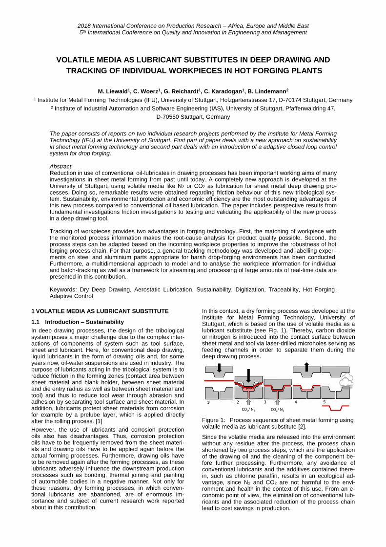
In this context, a dry forming process was developed at the Institute for Metal Forming Technology, University of Stuttgart, which is based on the use of volatile media as a lubricant substitute (see Fig. 1). Thereby, carbon dioxide or nitrogen is introduced into the contact surface between sheet metal and tool via laser-drilled microholes serving as feeding channels in order to separate them during the deep drawing process.
1 2 3 4 5
CO2/ N2 CO2/ N2
Figure 1: Process sequence of sheet metal forming using volatile media as lubricant substitute [2].
Since the volatile media are released into the environment without any residue after the process, the process chain shortened by two process steps, which are the application of the drawing oil and the cleaning of the component be-fore further processing. Furthermore, any avoidance of conventional lubricants and the additives contained there-in, such as chlorine paraffin, results in an ecological ad-vantage, since N2 and CO2 are not harmful to the envi-ronment and health in the context of this use. From an e-conomic point of view, the elimination of conventional lub-ricants and the associated reduction of the process chain lead to cost savings in production.

In the following, an expert of gained results using aerostat-ic lubrication in deep drawing processes of a rectangular cup is presented.
1.2 Dry deep drawing – tool design
In order to reduce the drilling depth for the laser process without reducing the tool strength a segmented tool design was chosen (see Figure 2). The base plate contains the holes for the media supply and a sealing to avoid an un-controlled flow out between the plates while the upper plate contains different supply channels and laser-drilled microholes. The position of the supply channels deter-mines the location of microholes. In order to avoid a free flow out of the media through the microholes due to blank edge draw-in right at the end of the forming process the position of the supply channels was optimized using a sheet metal forming simulation of the blank draw-in. As a result, one ring channel was integrated next to the die ra-dius and four additional channels were arranged with re-gard to the blank draw-in. Each supply channel can be controlled separately by a valve to stop free flow out of volatile lubricant during deep drawing.
One row of microholes was drilled perpendicular into the supply channel having a depth of 5 mm and one row was incorporated by an angle of 35° and a length of around 7 mm. Additional microholes were placed in the die radius area. In total, 154 microholes were distributed over the tool surface of the die. For the blankholder, the same design was chosen though without radius. Here about 100 micro-holes were drilled into the tool.
Figure 2: Free flow out of the CO2 through laser-drilled microholes in the die of the deep drawing tool.
Due to some problems in the tool manufacturing, it was necessary to re-mill the die radius after die laser drilling. For this purpose, the tool was connected to a compressed air system applying a pressure level of 2 bar (0.2 MPa) during the milling process. By doing so, surprisingly none microhole was blocked due to the machining process. Also after the final hardening process of the tool, no blockage of the microholes could be observed. The final assembly of the tool is shown in Figure 2 while a free flow out of CO2 media through the laser-drilled microholes is activated.
1.3 Dry deep drawing – Experimental setup
The aim of this project is the development of a new meth-od for dry metal forming by using volatile media injected through laser-drilled microholes. Focus of research project was put on the investigation of any practical e.g. manufac-turing oriented feasibility of this new approach. Therefore, emerging process limits were investigated and compared to the conventional deep drawing process using mineral oil- or wax-based lubricants. A crucial task to be solved at
the beginning is determination of the valid process win-dow. Usually in research the blank holder force and the drawing ratio is varied in the deep drawing process in or-der to find maximum drawing depth without wrinkles or cracks. By doing so, the valid process window can be de-termined to find the feasible ranges of blank holder force versus achievable drawing depth without occurring tears or wrinkles. For non-rotational parts the drawing depth is used instead of the drawing ratio.
All drawing experiments were carried out using electrolytic galvanized sheet material DC05. The sheets were cleaned manually and then degreased in an acetone bath in order to remove remaining oil layers on the sheet. Liquid CO2 having an initial pressure level pinitial of 60 bar (6 MPa) and gaseous N2 exhausting at the same pressure level were used as temporarily acting lubricant for dry metal forming. The supply of the media was controlled by special valves being controlled with respect to press ram movement. The supply was switched on at moment of the first contact be-tween the tool and the sheet and shut down at the bottom dead center of the press. Additionally, drawing tests were performed with the lubricant Wisura ZO3368 (1.5 g/m²) were investigated using the same tool material. All tests were carried out on an AIDA servo press at a ram speed of 6 strokes per minute which corresponds approximately to a ram speed of 100 mm/s at the beginning of the forming process.
1.4 Dry deep drawing –Results und discussion
Presented approach for dry metal forming was tested suc-cessfully and so, a rectangular cup was deep drawn using N2 and CO2 as temporarily acting lubrication for the very first time. In accordance with former tests results investi-gating the coefficient of friction [3] and the deep drawing of a U-shaped profile geometry [4], the new lubrication sys-tem performed better than the conventional one using a mineral oil-based lubricant (see Figure 3).
0
100
200
300
400
500
600
700
800
900
1000
1100
1200
1300
25 30 35 40 45 50 55 60
Bla
nk
ho
lde
r fo
rce [
kN
]
Drawing depth [mm]
Process window
Schmierstoff ZO3368 CO2 N2_60 bar
Mineral oil
Mechanical
limit of tool
Mineral oil ZO3368
N2 (60 bar or
6 MPa)
CO2
Figure 3: Process windows for deep drawing of a rectan-gular cup using different lubrication systems.
The maximum drawing depth in these test could be in-creased from 45-50 mm to 57.5 mm by using CO2 and N2. This depth corresponds to the mechanical limit of the tool. By using lubricant ZO3368 only 50 mm as a maximum drawing depth was achieved. Also the fracture limit was raised up to 50% depending on the drawing depth by us-ing CO2 as well as N2. Thereby, CO2 performs better for deeper cups than N2. It is assumed that this is caused by different pressure levels acting in the gap between the sheet and the tool resulting by the different media [5]. In general this pressure in the gap pgap is influenced by mi-croholes (position, numbers, nozzle type), the initial pres-sure level of the injected media pinitial and the sealing effect between tool surface and the sheet. Also this sealing ef-fect is influenced by many factors such as the blankholder force FBlankholder, the tool and sheet surface roughness and the thinning and thickening of part flange during deep drawing. Finally, there are interactions between the seal-

2014 International Conference on Production Research – Africa, Europe and Middle East 3rd International Conference on Quality and Innovation in Engineering and Management
ing effect, the pressure level pgap and the height of the mean gap hgap between the sheet asperities and the form-ing tool. A schematic illustration of the conditions in the gap and the applied designations are shown in Figure 4.
Figure 4: Schematic illustration of the resulting pressure between sheet and tool.
By deep drawing with volatile media acting as lubrication not only the fracture limit, but also the wrinkle limit was increased noticeably (see Figure 3). This effect also can be explained by the assumption that the mean gap hgap and the pressure pgap mainly do influence the sheet metal forming behaviour. For lower blank holder forces a higher gap hgap occur without or with minimum contact areas be-tween the tool and the sheet asperities. While forming, wrinkles of 1st order develop due to increasing tension stress in the blank without prevention by the blank holder. Thereby, the pressure in the gap, which is a scalar quanti-ty acting in all directions, cannot avoid the local develop-ment of wrinkles. The outflowing gas through the wrinkles support such development additionally. Other tests indi-cate that the wrinkle limit is raised further by using a pres-sure pinitial of N2 higher than 60 bar (6 MPa). However, also the fracture limit can be increased extremely. This con-firms the assumption that the resulting pressure level pgap of the volatile media between the sheet and tool mainly influences the friction behaviour and therefore the forming limits of the deep drawing process of this new approach.
In addition to those investigations on process limits in deep drawing, the cooling effect on the sheet surface cau-sed by the Joule-Thomson effect during the expansion of CO2 and N2 was investigated. The temperature was measured visually after the deep drawing process using a thermal camera.
Max. Temperature: 29.4°C
Min. Temperature: -2.2°C
a) b)
Figure 5: Measured temperature on the part surface after deep drawing using (a) nitrogen and (b) liquid carbon dio-xide as volatile lubricant
In Figure 5, the visualized temperature is shown using nitrogen (a) and liquid carbon dioxide (b) as lubricant for the same process achieving a drawing depth of 35 mm by use of a blank holder force of 275 kN. The maximum mea-sured temperature (29.4°C) after deep drawing when ap-plying nitrogen appears almost similar to the sheet tem-perature when using mineral oil-based lubricants (30.1°C). The heating in the corner of the cup is caused by dissipat-ing forming energy and friction heat. By contrast, using liquid CO2 as temporally acting lubricant reduces the sheet
temperature in the flange area down to -2.2°C (see Figure 5(b)). Compared to the first deep drawing experiments u-sing a U-profile geometry [4], a cooling effect of only a few degrees Celsius was measured. The cooling effect merges much more significantly when deep drawing the rectangu-lar cup. Additional to that the control of valves also plays an important role. Finding the right timing to switch on and off the flow of media appear more complex for the drawing process of a rectangular cup having curved arrangements of microhole positions onto the tool surface and more complex draw-in compared to previous drawn part as de-scribed. Another reason might be given by effect of chan-ging flange thickness during drawing counteracting to local blank holder force. Small gaps between the tool and the sheet induced by small wrinkles of 1st order can occur supporting the flow out of the CO2 and therefore the cool-ing of the sheet due to high velocity of media. According to these results, the flow control and also the position of mi-croholes have to be optimized in further research work in order to reduce observed extreme cooling of the sheet. A different approach is given to use the cooling effect active-ly to reduce the heating in drawing process, while heating of parts due to friction heat and dissipating forming energy is undesirable.
However, overall presented results show that sheet metal forming by dry means based on temporally acting volatile media looks possible. Performed investigations show, that an equivalent substitution of mineral oil-based lubricants as well as an enhancement of process limits in sheet me-tal forming simultaneously were achieved. Especially when using nitrogen evaporating at a pressure level adjusted to respective process conditions looks extremely promising.
1.5 Dry deep drawing – Outlook
The progress in the use of volatile media as lubricant sub-stitutes in the deep drawing process in this paper was demonstrated based on achieved results. Thus, deepened knowledge could be gained experimentally and simulative-ly by examining emerging friction conditions in the tool contact zone. Furthermore, after deep drawing of approxi-mately 300 cups under dry as well as lubricated conditions none of the microholes were blocked by zinc abrasion or other effects. So it can be assumed that blockage of the microholes is not a limitating factor for this new approach. In a next step, these results have to be confirmed by pro-spective deep drawing endurance tests. Further performed measures also will be implemented into the test stand in further investigations. The tool radii of a new testing rig, which are subjected to high friction and wear loads, will be provided with feedholes for volatile media flow too. Com-plex friction conditions at tool radii and interactions with the deep-drawing process will be investigated in this new special testing rig. A further goal of future research is to expand the range of applications for zinc-coated steel sheets to include selected aluminium sheet materials, which poses enormous challenges with regard to a more complex tribological system and its susceptibility to failure. Furthermore, the theoretical knowledge of the friction be-haviour of volatile media in the tribological system is to be further deepened in order to understand and specifically influence the occurring effects and thus to ensure robust and stable deep drawing processes.
1.6 Acknowledgement
The scientific investigations of sustainability using volatile media are funded by the German Research Foundation (DFG) within the priority program SPP 1676 Dry Metal Forming - Sustainable Production by Dry Processing in Metal Forming.

2 TRACKING OF WORKPIECES IN DROP FORGING
2.1 Introduction
Hot forging is one of the technologies bearing a great po-tential of improvements in the spirit of Industry 4.0 [6]. The product quality and process stability are evaluated usually after forming or even after heat treatment, based on prop-erties of randomly selected workpieces. The state-of-the-art in industry show, that drop forging manufacturing lines and quality assurance department are working in different and disconnected digitalisation. As a result, the cause of scatter in the product properties today cannot be linked with the individual process variables and parameter fluctu-ations. Efficient data communication and exchange of ma-nufacturing data within a forging system can only be achie-ved by hard backtracking and linking online labelled mea-surements with physical workpiece, otherwise, correlations and patterns cannot be extracted. Furthermore, the reduc-tion of the scrap rate by adaptive process parameters ba-sed on incoming material or part properties cannot be achieved in an efficient manner.
Cannolly [7] in 2005 has reviewed the use of bar and ma-trix codes in assembly operations and for part tracking in an manufacturing environment. Types of codes, marking methods and machine vision equipment were compared and the superiority of matrix code labelling is emphasized. Denkena et al. [8] introduced a vibration assisted face milling technology enabling the machining of a matrix code or similar shapes into the component surface eliminating an additional marking step. Vedel-Smith et al. [9] devel-oped a matrix code marking strategy for green sand cas-tings where a flexible insert tool is used to emboss the mould itself before the melt is poured in. Montanini et al. [10] explored the possibilities of active infrared thermogra-phy in restoring covered and abraded marks obtained by laser, dot peen, impact, press and scribe marking on a steel surface.
The common application of part marking in forging com-panies today depends usually on the size of workpiece and the production rate. Large workpieces with small pro-duction numbers are tracked by using labels, needling or mechanical marking. Small workpieces being manufac-tured in high production volumes do allow batch tracking. The ability to sample accurate process data and to correct-ly assign them to corresponding workpieces is a major challenge regarding the heterogeneity of data sources concerning data formats, protocols and sampling rates. Hence, software modules are needed that uniformly trans-fers the collected data from the machine level to a factory-cloud level storage. Fundamentals of this concept are paved by Faul et al. [11].
The aim of this paper is on the one hand to formalise the know-how necessary for the workpiece tracking in forging plants using the state-of-the-art hardware and software techniques. On the other hand, a deep focus is put on further investigation of physical tags and data driven mod-elling of traceability. A successful workpiece tracking sys-tem needs robust tags and components wired with track-ing software running at both machine and factory-cloud level. In this context, at first a general workpiece tracking methodology is developed and supported with multi-dimensional modelling of data-driven-traceability built on PLC-based data acquisition and processing. This method-ology can be used to build a tailor-made tracking system. Second, practical tags appropriate for forging environment are investigated thoroughly and laser-engraving of Quick Response (QR)-codes are performed onto the hot surface of forged aluminium and steel workpieces. Finally, an assistance system for a single/batch tracking for that pur-pose is introduced in this paper.
2.2 Workpiece tracking metholodogy
This section introduces elements of a generalized meth-odology that can be tailored to a variety of production sys-tems found in forging plants. Workpieces can be tracked on a batch level or individually. Harshness of the process, tag durability, process and tagging speed at the end de-termines the tracking intensity. A complete production line may contain processes such as casting, extrusion, sawing, turning, transfer, storage, heating, forging, blasting and heat treatment. Process information can be stored in the factory-cloud and can be associated to a specific work-piece by means of a master-identity. It is not necessary to store the complete master-identity on a tag fixed to the workpiece. Local or temporary identities can be assigned and reused at the machine level provided that the corre-sponding master-identities are distinct. In case economic and physical conditions desire for the next process relabel-ling can be performed. Tracking of a workpiece over a master-identity using various local-identities throughout the production line requires networking of the technical tracking systems in real time. Manual identification, trans-fer and registration of identities can be a part of this net-work. Provided the practical realisation of such a network-ing, the overall tracking problem reduces to localized tracking of workpieces throughout individual processes.
Process Formalisation:
Process in a forging production line may be clustered into the following process categories (PC):
(PC1) Tag endures throughout the process.
(PC2) Tag does not endure throughout drop forg-ing prochess and
(PC3) batch processing is performed.
Processes belonging to PC1 category do not damage the tag applied onto the workpiece, so the tag can be identi-fied flawlessly after processing. Examples are storage, transfer or heat treatment. Workpieces qualified as scrap can be identified and registered easily. Processes belong-ing to PC2 category do damage the tag, but the sequential processing allows the tracking of the identity within and after processing according to the identity scanned before the process. Parts can be qualified as scrap during or right after the process. Especially scrap determined and sepa-rated during process has to be registered in real time, which can be automated or performed by manual trigger-ing. Applications belonging to the State-of-the-art such as force measurements and part proximity sensors located at grippers can be used for recognition of missing parts. Pro-cesses belonging to PC3 category do damage the tag as well, the individual identity of produced part unfortunately is lost since a dedicated portion of workpieces are pro-cessed within a short time frame. In this case individual re-labelling of each workpiece is not practical due to high pro-duction rate or other constraints given by logistics. Such processes (e.g.heat-treatment, blast cleaning) conse-quently permit only batches to be tracked. Individual infor-mation of workpieces processed together can be merged in a “statistical representation” stored in the factory-cloud and only can be associated to batches.
The operative tracking actions are tagging with the (part or batch) identity and tag scanning to recall the (part or batch) identity and the corresponding information in the factory-cloud. The computational tracking actions are lo-cating the identity in the factory network, providing the required information from the factory-cloud to the process machine and storing the generated production information to the factory-cloud.
The category of a process can be altered by a process redesign to improve the traceability. Workpiece conveyors or workpiece carriers with a strict preservation of pro-
2014 International Conference on Production Research – Africa, Europe and Middle East 3rd International Conference on Quality and Innovation in Engineering and Management
cessing order instead of a disorderly transfer are trivial examples for such an improvement. At least, small work-piece containers providing reduced batch sizes can be used to increase the specificity of the statistical represen-tation of the associated information.
Programmable Logic Controller (PLC) based data acquisi-tion and processing:
The individual interfaces of the connector software do run on control devices and the standardized interface is oper-ating in the factory-cloud. The individual interface is basi-cally implemented as state machine that can be integrated into the PLC code. Two major cycles can be distinguished. Firstly, a “read”-cycle that scans the protocol and extracts data depending on the bus system. Secondly, a “write”-cycle that uses a Representational State Transfer model to describe the extracted data. The measured process pa-rameters are converted and mapped onto the model and posted to the standardized interface that runs on the cloud server. The standardized interface forwards the data for further processing. It is either stored in a relational data-base where data analytics techniques are applied or for-warded to a real-time database in order to conduct ad-hoc calculations and online analytical processing. The real-time database is used for the association of workpiece identity and process parameters along the entire process chain. It allows an online tracking of single parts or batch-es. The general concept is depicted in Figure 6.
Figure 6: Concept and system architecture.
2.3 Practical tags and tagging experiments
The design of a complete tracking system considers ap-plied processes, part geometry and material. The discus-sion in this field is limited to the comparison of the known characteristics of the tag. In this context, laser-engraving tests on hot steel and aluminium surfaces have been con-ducted and the results are compared to needling technol-ogy. Part or batch tracking solutions for operations such as machining, sawing, transfer or storage are already in use in industry. The harsh forging environment, possibly cover-ing heating of billet, forging, blasting and heat treatment allow use of cips for Radio Frequency Identification (RFID), labelling, needling, marking, laser-engraving and virtual tagging to be useful throughout these processes. Tags should not cause any harm, they must endure and could be tagged around 500°C for aluminium and 1200°C for steel. Oxide-layer has to be removed before tagging, but the tag endure the development of the oxide-layer as shown in Figure 7. A heatproof RFID is durable up to 350 °C at the transponder, [12], with a size of 10×7×3 cm be-ing practical on containers for batch tracking. There are also labels durable up to 1250°C, providing flexible size and content for individual or batch tracking [13]. Difficulties may arise when attaching, keeping and removing the la-bels. Although they are just superficial, needling, marking and laser-engraving become a part of the workpiece. They affect the geometry and even the material locally. Table 1 compares functionality of needling, marking, laser-engraving based on market research conducted during experiments.
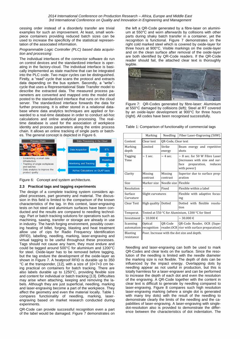
QR-Code can provide successful recognition even a part of the label would be damaged. Figure 7 demonstrates on
the left a QR-Code generated by a fibre-laser on alumini-um at 550°C and worn afterwards by collisions with other parts during shaky batch transfer in a container, yet the recognition is functional. Figure 7 demonstrates on the right cold marked steel which is covered by oxide-layer for three hours at 900°C. Visible markings on the oxide-layer and on the clean surface after removal of the oxide-layer are both identified by QR-Code readers. If the QR-Code reader should fail, the attached clear text is thoroughly legible.
Figure 7: QR-Codes generated by fibre-laser: Aluminium at 550°C damaged by collisions (left); Steel at RT covered by an oxide-layer development at 900°C for three hours (right). All codes have been recognised successfully.
Table 1: Comparison of functionality of commercial tags
Needling and laser-engraving can both be used to mark QR-Codes and clear texts on the surface. Since the reso-lution of the needling is limited with the needle diameter the marking size is not flexible. The depth of dots can be influenced by the impact energy. Overlapping dots by needling appear as not useful in production, but this is totally harmless for a laser-engraver and can be performed to increase the depth of each dot and even the resolution of the engraving. A QR-Code together with the content in clear text is difficult to generate by needling compared to laser-engraving. Figure 8 compares such high resolution laser-engraving marking (where a single dot is generated with many tiny dots) with the result of the needling to demonstrate clearly the limits of the needling and the ca-pabilities of laser-engraving. A laser-engraving with single-dot-resolution also is provided to demonstrate the differ-ence between the characteristics of dot indentation. The
Marking Needling Fiber Laser-Engraving (50W)
Content Clear text QR-Code, Clear text
Marking depth
Limited Strike energy
Beam energy and repetitive shots
Tagging Time
~ 1 sec. ~ 4 sec. ~ 8 sec. for 50 W Fibre Laser (increases with size and sur-face preparation, reduces with power)
Clarity Missing contrast
Missing contrast
Superior due to surface prep-aration
Size Marker size Needle size Flexible
Resolution - Fixed Flexible within a label
Surface Curvature
Slight curvatures Flexible with adaptive focus-ing
Clear Text High quality Dotted Dotted with flexible resolu-tion
Temperat. Tested at 550 °C for Aluminium, 1200 °C for Steel
Investment ~ 10.000 € ~ 30.000 €
Scanning automation
Optical recognition
QR-Code reader,OCR
QR-Code Reader, OCR (Supe-rior with surface preparation)
Blasting resistance
Poor. Increase with the dot size and depth.

size and depth of the dots in QR-Code has to be increased for a better durability against blast-cleaning.
Figure 8: QR-Codes generated by needling (left), low reso-lution laser-engraving (middle) and high resolution laser engraving (right), all with successful optical recognition.
2.4 Conclusion of tracking of workpieces in drop
forging environments
Authors propose a general workpiece tracking methodolo-gy for hot forging plants covering process formalisation, multidimensional modelling of data-driven-traceability and PLC-based data acquisition and processing. Practical so-lution of tag design were reviewed and compared in this paper and tagging experiments were performed to extend the possibilities of individual workpiece tracking also. The realisation of individual workpiece tracking for high produc-tion rates requires re-design of processes like transfer, storage heating and heat treatment based on the intro-duced process formalisation. Real-time registration of scraps is a requirement in the tracking problem. QR-Code with clear text extension is suggested for manually aided automation. Standard QR-Codes use square dots fully covering the grid-cell in the code. Needling and laser-engraving with single-dot-resolution for each grid-cell however generate round dots without filling that grid-cell. Furthermore, the colour and contrast in a dotted grid-cell is not optimal. Readability of a QR-Code depends on the recognition of a dot, having a distinguished contrast from a free grid-cell. Since digital image correlation based identi-fication of QR-Code does consider this standardised prax-is, which is biased towards the printed codes with sharp and recognizable gradients in contrast, identification of the engraved codes may fail in case of bad lighting. In this study, commercial readers were used and mostly success-ful results are obtained with proper lighting.
2.5 Acknowledgement
This work was supported by the German Federal Ministry for Economic Affairs and Energy within the framework of the Programme for Competition Digital Technologies for Business. Funding period: 2017 – 2019.
3 REFERENCES
1. Vollertsen, F., Schmidt, F., “Dry metal forming: Definition, Chances and Challenges,” Int. J. Pre-cis. Eng. Manuf. - Green Technol., vol. 1, no. 1, pp. 59–62, (2014).
2. Liewald, M., Graf, T., Hirth, T., et al., “Tribosys-teme für die Kaltumformung auf der Basis von flüchtigen Schmiermedien und laserstrukturierten Oberflächen,” Dry Met. Form. OAJ FMT 1, vol. 1, pp. 22–33, (2015).
3. Woerz, C., Liewald, M., Singer, M., “Investigation of Tribological Conditions in the Strip Drawing Test Using Liquid CO2 and N2 as a Volatile Lubri-cant,” 7th International Conference on Tribology in Manufacturing Processes (ICTMP), pp. 140–148, (2016).
4. Woerz, C., Zahedi, E., Umlauf, G., et al., “Tiefziehen eines U-Profils mit flüchtigen Medien als Schmierstoffersatz“, Dry Met. Forming OAJ FMT, 3, 50-61, (2017).
5. Woerz, C., Reichardt, G., Liewald, M., Zahedi, E., Weber, R., “Dry deep drawing of a rectangular cup assisted by volatile media injected from la-ser-drilled microholes,” Dry Met. Form. OAJ FMT 4, vol. 4, pp. 1–8, (2018).
6. Liewald, M., Karadogan, C., Felde, A., Lodwig, R., 2017, Development and Integration of Digital Technologies in the Forging Process Sequence, New Developments in Forging Technology, 245-256.
7. Connolly, C., 2005, Part‐ tracking labelling and machine vision, Assembly Automation, 25/3:182-187.
8. Denkena, B., Grove, T., Seibel, A., 2016, Direct Part Marking by Vibration Assisted Face Milling, Procedia Technology, 26:185-191.
9. Vedel-Smith, N.K., Lenau T.A., 2012, Casting traceability with direct part marking using recon-figurable pin-type tooling based on paraffin–graphite actuators, Journal of Manufacturing Sys-tems, 31:113-120.
10. Montanini, R., Quattrocchi, A., Piccolo, S.A., 2016, Active thermography and post-processing image enhancement for recovering of abraded and paint-covered alphanumeric identification marks, Infrared Phys Technol., 78:24-30.
11. Faul, A., Jazdi, N., Weyrich M., 2016, Approach to interconnect existing industrial automation sys-tems with the industrial internet. 21st IEEE Inter-national Conference on Emerging Technologies and Factory Automation (ETFA) 2016.
12. http://sawcomponents.de/produkte/saw-sensorik-und-rfid/
13. http://heatproof.eu/produc