a dynamic motion control technique for human-like ... · a dynamic motion control technique for...
TRANSCRIPT
EUROGRAPHICS 2001 / A. Chalmers and T.-M. Rhyne(Guest Editors)
Volume 20 (2001), Number 3
A Dynamic Motion Control Techniquefor Human-like Articulated Figures
Masaki Oshita and Akifumi Makinouchi
Department of Intelligent Systems, Graduate School of Information Science and Electrical Engineering, Kyushu University, Japan
AbstractThis paper presents a dynamic motion control technique for human-like articulated figures in a physically basedcharacter animation system. This method controls a figure such that the figure tracks input motion specified bya user. When environmental physical input such as an external force or a collision impulse are applied to thefigure, this method generates dynamically changing motion in response to the physical input. We have introducedcomfort and balance control to compute the angular acceleration of the figure’s joints. Our algorithm controls theseveral parts of a human-like articulated figure separetely through the minimum number of degrees-of-freedom.Using this approach, our algorithm simulates realistic human motions at efficient computational cost. Unlikeexisting dynamic simulation systems, our method assumes that input motion is already realistic, and is aimed atdynamically changing the input motion in real-time only when unexpected physical input is applied to the figure.As such, our method works efficiently in the framework of current computer games.
1. Introduction
Generating realistic character animation is a difficult chal-lenge. Recently, many online applications such as computergames and virtual environments require the generation ofrealistic and continuous character animation in real-time.Currently, such animations are generated by dynamicallycomposing motion sequences such as motion capture orkeyframed motion data. These motion sequences need to becreated in advance. Therefore, it is difficult to produce dy-namically changing motion that respond to physical inputfrom the environment, such as the gravitational force whencarrying a heavy load, an external force, or a collision im-pulse from other objects. This kind of interaction betweena character and the environment are frequent and importantevents in computer games. Nevertheless, very few methodshave been developed for dynamic motion control in such sit-uations. This is one of the most important issues in real-timecharacter animation.
This paper presents a dynamic motion control techniquefor human-like articulated figures. This method controls acharacter based on input motion specified by a user, and en-vironmental physical input in a physically based characteranimation system. In the system, the angular acceleration ofcharacter’s joints are controlled so as to track the usr-input
motion. Dynamic simulation then generates the resulting an-imation. When environmental physical input is applied to thecharacter, the dynamic motion control computes the angularjoint accelerations in order to produce dynamically chang-ing motion in response to the physical input. We introducetwo kinds of dynamic control; comfort and balance control.Under comfort control, when a torque on a joint exceeds theavailable muscle strength of the joint, the angular joint accel-erations are controlled so as to reduce the joint stress basedon the moment of inertia. Under balance control, when thecharacter is likely to lose balance, the angular joint accelera-tions are controlled so as to maintain balance. This approachproduces human-like dynamic motion control, such as re-ducing the stress on the back by swing the arms and main-taining balance by moving the pelvis, when the charactercarries a heavy load or collides with other objects. This dy-namic motion control method is specific to human-like artic-ulated figures, controlling the arms, back and legs separetelyin order of importance. Each part is controlled through theminimum number of degrees-of-freedom (DOF). A numberof minor factors are ignored in this method and the result-ing motion is not perfectly physically correct. However, ourmethod makes it possible to simulate realistic human mo-tions at lower computational cost because the method doesnot include heuristics. The goal of our method was not to es-
c The Eurographics Association and Blackwell Publishers 2001. Published by BlackwellPublishers, 108 Cowley Road, Oxford OX4 1JF, UK and 350 Main Street, Malden, MA02148, USA.
Oshita and Makinouchi / A Dynamic Motion Control Technique for Human-like Articulated Figures
tablish a stable control method but to produce realistic char-acter reactions in response to physical interactions.
A number of techniques have been developed for gener-ating character animation in real-time using dynamic simu-lation. However, most of these methods are aimed at gen-erating physically correct motion from unnatural input mo-tion such as specified keyframes and monotonous proceduralmotion. Because these methods cannot utilize existing real-istic motion sequences such as motion capture data, they arenot used in many applications. Our method assumes that in-put motion is already realistic, and is aimed at dynamicallychanging the input motion only when unexpected physicalinput is applied to the figure from the environment. As such,our method works efficiently in the framework of currentcomputer games and other online applications.
The reminder of this paper is organized as follows. Sec-tion 2 reviews related work and issues relevant to solve ourproblem. Section 3 describes the structure of proposed sys-tem and its components. Section 4 presents a simple trackingcontrol algorithm to track an input motion directly. Basedon the tracking controller, section 5 then introduces a dy-namic control algorithm for comfort and balance control. Insection 6, an experimental result is presented, and section 7concludes this paper and outlines future research.
2. Related Work
There are two main approaches for generating or editingphysically correct motion based on dynamics; spacetimeconstraints and dynamic simulation. In addition, there aremotion control techniques using dynamics for specific task.
2.1. Spacetime Constraints
In the spacetime constraints approach 20, an optimal motiontrajectory is automatically computed such that the resultingmotion minimizes an objective function based on spacetimeconstraints specified by the user. Rose et al. 15 adapted thisapproach to articulated figures and proposed a keyframe in-terpolation technique in whitch the required torque, calcu-lated using inverse dynamics for each motion segment be-tween specified keyframes is minimezed. Komura et al. 9 in-troduced a musculoskeletal model and an objective functionfor minimizing muscle strength, thus allowing input motionto be retargeted to other characters with different muscu-loskeletal models. Tak et al. 16 proposed a motion balancefiltering technique that modifies an input motion sequencesuch that the balance of the figure is maintained during mo-tion making dynamic adjuctments to the trajectory of thezero moment point (ZMP). These methods are effective forconverting input motion to more realistic motion. Recently,Popovic and Witkin 14 proposed a transformation techniquebased on a spacetime constraint approach and dynamics.This method involves extracting the essential physical char-acteristics from an original motion for the simplified model
using the spacetime constraints approach, and then modif-ing the extracted dynamics and reconstruct the resulting mo-tion for the original articulated figure. By this method, thedynamics of an existing motion sequence can be modifiedeasily. However, this method does not model the character’sskeleton or strength. Furthermore, no human-like dynamiccontrol is employed.
Although the spacetime constraint technique makes itpossible to edit motion, ensuring both controllability andphysical realism, the technique is difficult to apply prac-tically for two reasons. First, animations cannot be pro-duced in real-time because solving an optimal problem re-quires significant computational time, hence an offline pro-cess. Second, because the spacetime constraint techniquecontrols motion in angular space, it is difficult to realize mo-tion that interacts dynamically with the environment. Duringstatic motion, joint stress and overall body balance dependon primarily joint angle. However, during dynamic motion,the effect of the moment of inertia due to angular joint accel-eration should also be considered. The spacetime constrainttechnique controls joint angle, and indirectly controls angu-lar joint acceleration. The technique is suitable for planningstable motion by minimizing joint stress and maintainingbalance before motion is initiated. However, the techniqueremains unsuitable for dynamic control in which the figureis required to incidental physical input during motion.
2.2. Dynamic Simulation
Dynamic simulation methods use a dynamic controller tocompute joint torques based on the current state and the de-sired motion. Forward dynamics simulation then generatesthe resulting motion based on joint torque. A number ofresearchers have developed dynamic controllers for a spe-cific character skeletons and behavior, such as for walk-ing 3 18 and athletic movements 6. These controllers useproportional-derivative (PD) servos to compute joint torquebased on the desired and current angle for each joint. The PDcontroller determines the output torque in proportion to thedifference between the desired state θd , θd and the currentstate θ, θ (vector of angles and angular velocities, respec-tively) according to
τ = kp(θd �θ)+ kv(θd � θ): (1)
The PD controller is easy to implement. However, the tech-nique does not account for the dynamic characteristics of thesystem. Therefore, to produce stable and natural motion, theproportional gains kp and kv need to be tuned empirically forboth the character and motion. van de Panne 18 developed anoptimization technique so as to tune the various parametersof gait motion. Hodgins and Pollard 5 proposed a transfor-mation technique that transforms a successful controller toanother character. However, it remains difficult to constructa controller that works successfully. Furthermore, becausethese systems combine dynamic controllers and reference
c The Eurographics Association and Blackwell Publishers 2001.
Oshita and Makinouchi / A Dynamic Motion Control Technique for Human-like Articulated Figures
motion generators that are specific for a particular task, itis difficult to adopt the model for other motions.
Recently, more advanced controllers for tracking kinemat-ically specified general motion sequences have been pro-posed. Zordan and Hodgins 21 proposed a dynamic con-troller for general human upper-body motion. They com-bined the PD controller and optimal control in their system,optimal parameters kp and kv are determinded so as to mini-mize the error between the desired and produced motion se-quences. However, because determining the parameters re-quires an offline process, this method is not suitable for real-time applications. Kokkevis et al. 8 introduced model refer-ence adaptive control (MRAC) as a replacement for PD con-trol. They developed a MRAC controller that takes a conver-gence speed of the reference model as the parameter insteadof gain parameters.
Existing dynamic simulation methods are aimed at gener-ating physically correct motion based on physically unnatu-ral input motion such as manually specified keyframes andmonotonous procedural motions. Using dynamic simulation,these methods generate motion that reflects a figure’s physi-cal properties and accounts for external input such as exter-nal force or impact. However, these methods do not includeactive control such as the comfort and balance controls pre-sented in this paper. These methods control each DOF sep-arately, failing to consider the effect of joint torque on theangular acceleration of other joints.
2.3. Motion Control using Dynamics
A number of techniques have been developed for generat-ing dynamically controlled motion based on dynamics fora particular kind of task. Lee et al. 11 introduced a musclestrength model into the inverse kinematics method, modify-ing the trajectory of an end-effecter and motion speed basedon the muscle strength of the joints. Boulic et al. 2 developedthe inverse kinetics method to control the trajectory of thecenter of mass of an articulated figure. These methods makeit possible to create motion that includes comfort and bal-ance control. However, they are unable to handle the changeof velocity of an articulated figure due to a collision impulse,nor can they make use of existing motion data.
Ko and Badler 7 developed system that produces a hu-man walking motion with balance and comfort control usinginverse dynamics. They combined a walking motion gen-erator and dynamic modification of the generated walkingmotion. The system transforms the positions of the pelvisand torso during the generated walking motion, and con-trols walking speed in response to the joint torques calcu-lated by inverse dynamics in real-time. However, the com-putation of displacement does not include dynamics and re-mains dependent on empirically tuned parameters. Further-more, the method is unable to handle interactions with theenvironment.
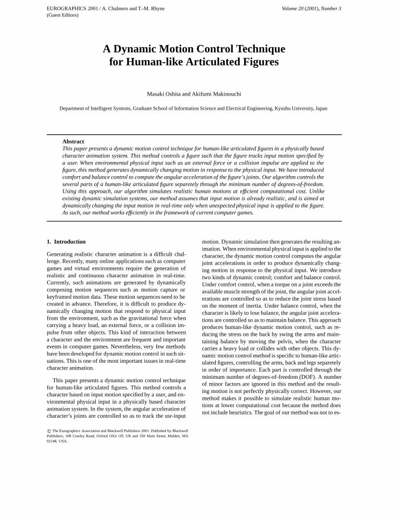
Controller
Input Motion Human Body Model
Angular Acceleration
Current StateSimulator
External Force and Impulse
Figure 1: System structure.
3. System Description
The structure of the animation system presented in this paperis shown in Figure 1. The system consists of two main mod-ule; a controller and a simulator. At each simulation step,the controller computes the angular joint acceleration of thefigure, based on the current state of the figure and the mo-tion input by a user. The simulator then updates the stateof the figure through dynamic simulation. A human bodymodel and external physical input are considered in both thecontroller and the simulator. Unlike standard controllers 6 8
21 control joint torque, our controller controls angular jointacceleration directly. No forward dynamics are used in oursystem. Instead, inverse dynamics is used in the controller totake into account the torque required to realize a given angu-lar acceleration. The algorithm for the controller is presentedin detail in section 4 and 5. The remainder of this section ex-plains the other components in the system.
3.1. Human Body Model
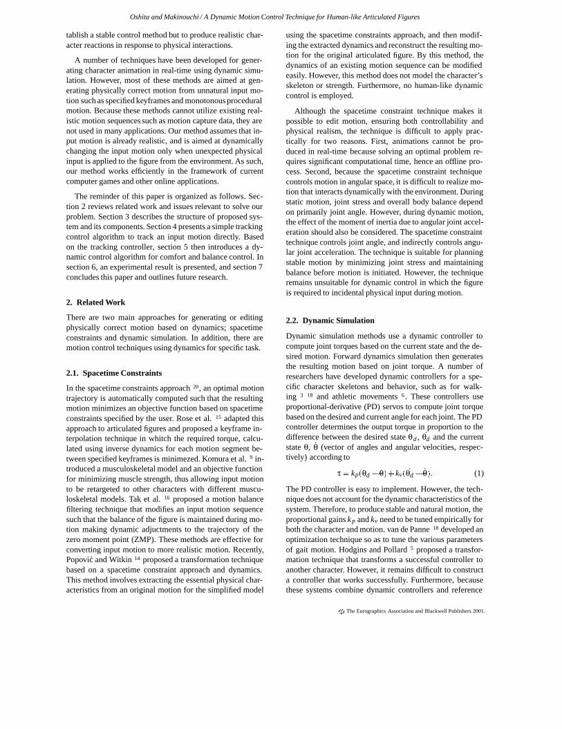
The human body model considered by this method is as anarticulated figure, which is a common representation in char-acter animation. The articulated figure consists of segmentsand joints; each rigid segment is connected by one, two, orthree rotational joints. For example, the shoulder has threejoints and the elbow has one. Based on this skeleton model,the configuration of a figure is represented by the set of an-gles of all joints and the position and orientation of the rootsegment. In addition, each segment has physical propertiesrelevant to dynamic simulation, such as mass and momentof inertia. These properties are calculated from the polygo-nal geometry of each segment 6. The polygonal geometriesalso are used for collision detection and for computing thecontact surface between the segment and the ground. For ourexperiments, we use a skeleton model that has 18 segmentsand 39 joints (Figure 2).
The dynamic controller uses the available muscle strengthof each joint as the criterion for comfort control. We adopta simple muscle strength model 7 11 in whitch two musclestrength functions; the maximum and minimum availabletorque, are assigned to each joint. Pandya et al. 13 showedby collecting human strength data that these values can beapproximated by functions of the joint angle and angularvelocity. We assigned approximated strength functions to
c The Eurographics Association and Blackwell Publishers 2001.
Oshita and Makinouchi / A Dynamic Motion Control Technique for Human-like Articulated Figures
1DOF
3DOF
3DOF
3DOF3DOF3DOF
3DOF
3DOF
1DOF
1DOF
xz
y
Figure 2: Human skeleton model.
each joint, taking into account references including musclestrength data 13 11.
3.2. Motion Representation
Desired motion is specified in terms of the displacementsof the configuration of a figure over time. Therefore, motiondata are expressed as the angular trajectories of all joints andthe spatial and orientational trajectory of the root segment. Inaddition, while a foot is in contact with the ground, the jointsof the leg is controlled such that the foot is held in the sameposition (as explained in section 4.2). Therefore, the timewhen each foot lands on the ground and leaves again shouldalso be indicated. As input motion is represented kinemati-cally, any form of motion capture data or keyframe motionsequence can be used as an input to our system.
3.3. Dynamic Simulation
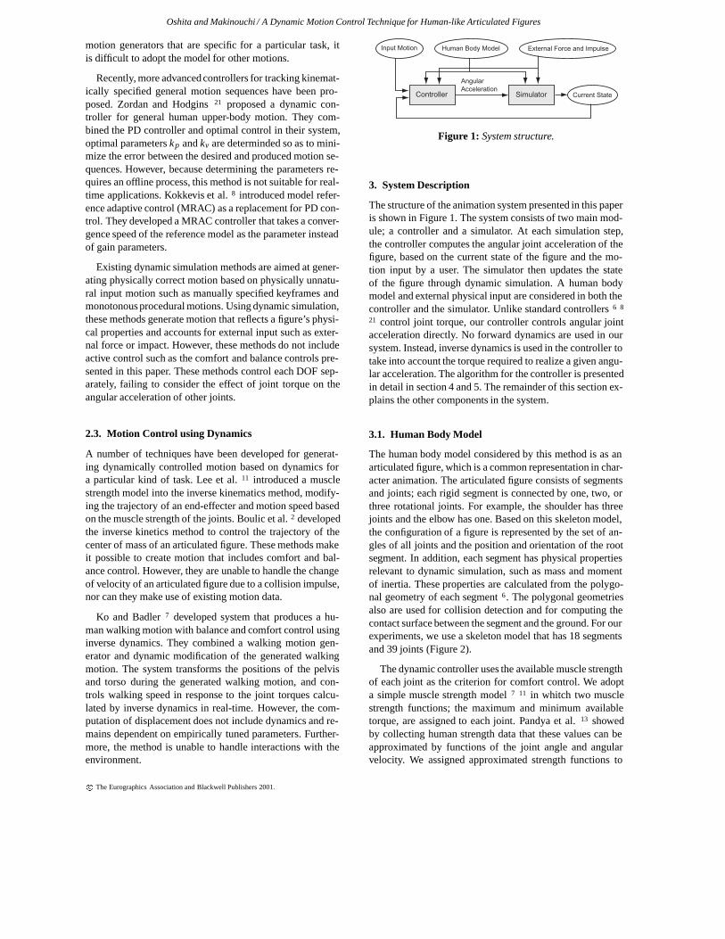
Given the angular accelerations of all joints, the simulatorupdates the angles and angular velocities of all figures byEular integration ?. In addition to the angular acceleration ofthe joints, the rotational acceleration of the supporting seg-ment of the figure (e.g. foot) is computed based on the an-gular joint acceleration, simulating falling motion. The seg-ment upon which the moment of the center of mass of thefigure is maximum is chosen as the supporting segment. Tocompute the rotational acceleration of a supporting segment,we use the zero moment point (ZMP) and minimum momentpoint (MMP). The details of the concept of the ZMP are ex-plained in 16. The ZMP is the point where the torque exertedby the figure on the ground is zero. When ZMP is within thesupport area (Figure 3(a)), the figure is balanced and there isno rotational acceleration of supporting segment. Otherwise,rotational acceleration occurs around the MMP where theexerted torque is minimum. The MMP is the closest pointfrom the ZMP within the support area (Figure 3(b)). Thesupport area is the convex hull of contact surfaces betweenthe foot segments and the ground. The rotational accelera-tion of the supporting segment is computed from the torque
exerted on the MMP and the moment of inertia of the wholebody in that configuration. After the integration, collisiondetection and response are performed. When two figures col-lide, an impact force is imparted on each and their velocitieschange. The velocity changes are computed by solving thelinear equation 12 8. If the figures remain in contact, a re-action force acts between them. Reaction forces and otherexternal forces are considered in the inverse dynamics com-ponent of the dynamic controller.
ZMP
ZMP
MMP
(a) (b)
Figure 3: ZMP in (a) balanced and (b) unbalanced state.
4. Tracking Control
This section presents the algorithm used to compute the an-gular acceleration of all joints so as to track the desired mo-tion, based on the current state of the figure and the desiredmotion. This algorithm controls joint angular accelerationdirectly rather than via joint torque, witch is the case in stan-dard dynamic simulation systems. As result, the desired mo-tion is almost exactly tracked. However, unlike standard an-imation and game systems in which the joint angles of a fig-ure are directly controlled according to a desired motion tra-jectory, our tracking controller produces continuous motionthat approaches the desired motion even when the velocity ofthe figure is changed through a collision. In addition, when afigure loses its balance, a falling motion is generated as ex-plained in section 3.3. The algorithm presented here is a sim-ple and direct tracking control. A more advanced dynamiccontrol for realizing human-like movements is presented inthe next section as an extension of this tracking control sys-tem. This tracking control also can be used alone, if a userrequires only continuous motion and lower computationalcost. This tracking control scheme does not require dynam-ics computations or muscle strength model, making it easilyto implement, with low computational cost.
4.1. Angular Acceleration of Each Joint
The angular acceleration for each joint is computed based onthe figure’s current state (joint angle and angular velocity),
c The Eurographics Association and Blackwell Publishers 2001.
Oshita and Makinouchi / A Dynamic Motion Control Technique for Human-like Articulated Figures
and the angular trajectory of the desired motion. As reviewedin section 2.2, PD control servos are widely used for thispurpose in existing dynamic simulation systems 6 3 18. Usinga PD controller, the output angular acceleration is computedusing the following equations;
θ = kp(θd �θ)+ kv(θd � θ) (2)
where (θ; θ) is the current joint angle and angular acceler-ation, (θd ; θd) is the desired state obtained from a desiredjoint angular trajectory after ∆t , and kp and kv are the gainparameters. The parameters need to be tuned for each jointand each motion, making it difficult to contruct a generalcontroller by this approach. In addition, to realize a stablecontrol, a controller should take into account not only onestate in the desired angular trajectory after ∆t , but also theentire trajectory.
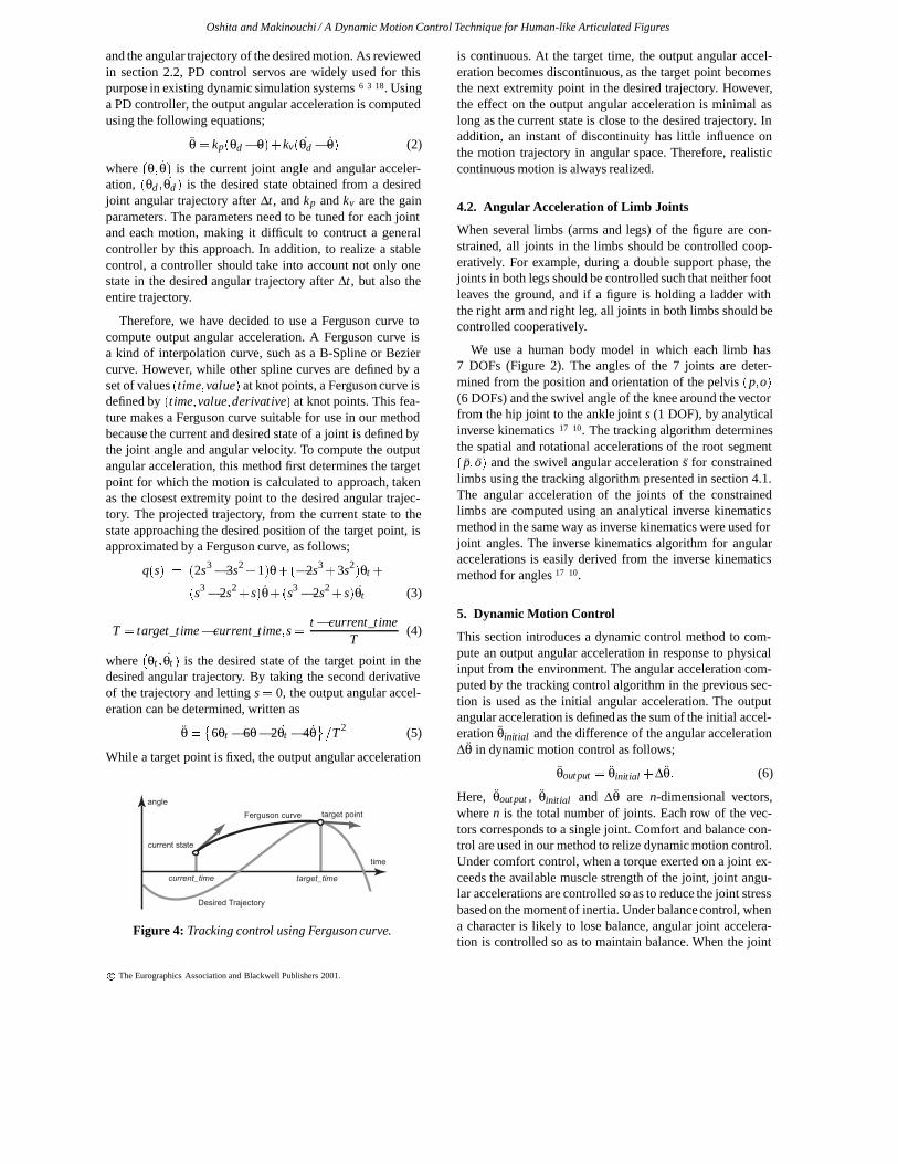
Therefore, we have decided to use a Ferguson curve tocompute output angular acceleration. A Ferguson curve isa kind of interpolation curve, such as a B-Spline or Beziercurve. However, while other spline curves are defined by aset of values (time;value) at knot points, a Ferguson curve isdefined by (time;value;derivative) at knot points. This fea-ture makes a Ferguson curve suitable for use in our methodbecause the current and desired state of a joint is defined bythe joint angle and angular velocity. To compute the outputangular acceleration, this method first determines the targetpoint for which the motion is calculated to approach, takenas the closest extremity point to the desired angular trajec-tory. The projected trajectory, from the current state to thestate approaching the desired position of the target point, isapproximated by a Ferguson curve, as follows;
q(s) = (2s3�3s2
+1)θ+(�2s3+3s2
)θt +
(s3�2s2
+ s)θ+(s3�2s2
+ s)θt (3)
T = target_time� current_time;s =t � current_time
T(4)
where (θt ; θt ) is the desired state of the target point in thedesired angular trajectory. By taking the second derivativeof the trajectory and letting s = 0, the output angular accel-eration can be determined, written as
θ =�
6θt �6θ�2θt �4θ=T 2 (5)
While a target point is fixed, the output angular acceleration
angle
time
current state
target pointFerguson curve
Desired Trajectory
current_time target_time
Figure 4: Tracking control using Ferguson curve.
is continuous. At the target time, the output angular accel-eration becomes discontinuous, as the target point becomesthe next extremity point in the desired trajectory. However,the effect on the output angular acceleration is minimal aslong as the current state is close to the desired trajectory. Inaddition, an instant of discontinuity has little influence onthe motion trajectory in angular space. Therefore, realisticcontinuous motion is always realized.
4.2. Angular Acceleration of Limb Joints
When several limbs (arms and legs) of the figure are con-strained, all joints in the limbs should be controlled coop-eratively. For example, during a double support phase, thejoints in both legs should be controlled such that neither footleaves the ground, and if a figure is holding a ladder withthe right arm and right leg, all joints in both limbs should becontrolled cooperatively.
We use a human body model in which each limb has7 DOFs (Figure 2). The angles of the 7 joints are deter-mined from the position and orientation of the pelvis (p;o)(6 DOFs) and the swivel angle of the knee around the vectorfrom the hip joint to the ankle joint s (1 DOF), by analyticalinverse kinematics 17 10. The tracking algorithm determinesthe spatial and rotational accelerations of the root segment( p; o) and the swivel angular acceleration s for constrainedlimbs using the tracking algorithm presented in section 4.1.The angular acceleration of the joints of the constrainedlimbs are computed using an analytical inverse kinematicsmethod in the same way as inverse kinematics were used forjoint angles. The inverse kinematics algorithm for angularaccelerations is easily derived from the inverse kinematicsmethod for angles 17 10.
5. Dynamic Motion Control
This section introduces a dynamic control method to com-pute an output angular acceleration in response to physicalinput from the environment. The angular acceleration com-puted by the tracking control algorithm in the previous sec-tion is used as the initial angular acceleration. The outputangular acceleration is defined as the sum of the initial accel-eration θinitial and the difference of the angular acceleration∆θ in dynamic motion control as follows;
θout put = θinitial +∆θ: (6)
Here, θout put , θinitial and ∆θ are n-dimensional vectors,where n is the total number of joints. Each row of the vec-tors corresponds to a single joint. Comfort and balance con-trol are used in our method to relize dynamic motion control.Under comfort control, when a torque exerted on a joint ex-ceeds the available muscle strength of the joint, joint angu-lar accelerations are controlled so as to reduce the joint stressbased on the moment of inertia. Under balance control, whena character is likely to lose balance, angular joint accelera-tion is controlled so as to maintain balance. When the joint
c The Eurographics Association and Blackwell Publishers 2001.
Oshita and Makinouchi / A Dynamic Motion Control Technique for Human-like Articulated Figures
torque is within the available muscle range for all joints andthe body balance is maintained on θinitial , no dynamic con-trol is performed and the controller outputs the initial accel-eration θinitial as the output acceleration. In this way, motionclose to the desired motion trajectory is realized.
5.1. Control Foundation
The criteria for comfort and balance control are introducedhere in terms of the dynamics of articulated figures. The cri-teria and the use of comfort and balance control is not novelwork. The novel part of our work is the dynamic control al-gorithm that controls angular joint acceleration. Here, therelationship between the criteria and the angular accelera-tion of a joint is derived for the dynamic control altorithmsedcribed in section 5.3.
5.1.1. Comfort Control
Joint torque that exceeds available muscle strength is con-sidered as the criterion for comfort control. The joint torqueτ required to produce the joint acceleration θ is computed byan inverse dynamics method, expressed as
τ = H(θ)θ+C(θ; θ)+G(θ)+F(θ) (7)
where H(θ) is the moment of inertia, and C(θ; θ), G(θ) andF(θ) are the influences on torque due to coriolis and cen-trifugal forces, gravity, and external force, respectively. Thedimension of all vectors is n, where n is the number of jointsof the figure. For the inverse dynamics, we use the Newton-Eular method 4. During a double support phase, an approx-imation 7 9 is used to determine the forces applied from theupper body to each leg. The required torque of all joints iscomputed in O(n). The available torque of the ith joint is de-pend on (θi; θi) as explained for the muscle strength modelin section 3.1 and given by
τmax;i = fmax;i(θi; θi); τmin;i = fmin;i(θi; θi): (8)
The requiered change in joint torque to satisfy the musclestrength constraint is computed for each joint by the follow-ing equation;
τstress;i =
8<:
τi � τmax;i; if τi > τmax;iτi � τmin;i; if τi < τmin;i
0; if τmin;i < τi < τmax;i
(9)
Comfort control is performed so as to minimize τstress;i forall joints.
The relationship between the required change in jointtorque ∆τ and the corresponding change in angular joint ac-celeration can be derived from equation (7). The relationshipis dependent on the moment of inertia, as follows;
∆τ = H(θ)∆θ: (10)
Each column of the matrix H(θ) is computed solely fromthe current angles in O(n) 19. Comfort control is performedbased on the derivation of the joint torque in equation (10).
5.1.2. Balance Control
The zero moment point (ZMP) and minimum moment point(MMP), explained in section 3.3, are used as the criterion forbalance control. The position of the ZMP is computed fromthe spatial accelerations of all segments on the assumptionthat the ground is defined as ZMPy = 0 according to the fol-lowing equations 16;
ZMPx =∑mixi(yi �g)�∑miyixi
∑mi(yi�g); (11)
ZMPz =∑mizi(yi �g)�∑miyizi
∑mi(yi �g)(12)
where mi is the mass of the ith segment, (xi;yi;zi) is the po-sition of the ith segment, and (xi; yi; zi) is the spatial acceler-ation of the ith segment. As the spatial accelerations of seg-ments are computed from the angular acceleration of joints,the position of the ZMP is represented as a function of angu-lar joint acceleration. When ZMP is outside the support area,the MMP becomes the closest point from the ZMP within thesupport area. Balance control is performed to move the ZMPto the MMP (Figure 3(b)).
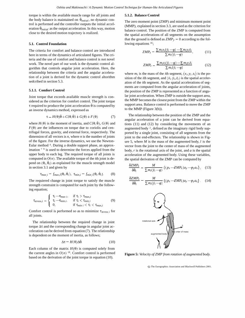
The relationship between the position of the ZMP and theangular acceleration of a joint can be derived from equa-tions (11) and (12) by considering the movements of anaugmented body 2, defined as the imaginary rigid body sup-ported by a single joint, consisting of all segments from thejoint to the end-effecters. The relationship is shown in Fig-ure 5, where M is the mass of the augmented body, l is thevector from the joint to the center of mass of the augmentedbody, r is the rotational axis of the joint, and a is the spatialacceleration of the augmented body. Using these variables,the spatial derivation of the ZMP can be computed by
δZMPx
δθi=
M
∑mi(yi �g)f(px�ZMPx)ay� pyaxg ; (13)
δZMPx
δθi=
M
∑mi(yi�g)f(pz�ZMPz)ay� pyazg : (14)
rotational axis
augmented bodythe cnter of mass
la
joint
Figure 5: Velocity of ZMP from rotation of augmented body.
c The Eurographics Association and Blackwell Publishers 2001.

Oshita and Makinouchi / A Dynamic Motion Control Technique for Human-like Articulated Figures
Balance control is performed based on the spatial derivationof the ZMP in equations (13) and (14).
5.2. Control Strategy
A simple approach for computing ∆θ is to solve an optimiza-tion problem so as to minimize an objective function such as
f (∆θ ) = jτstressj+ jZMP - MMPj+��∆θ
��: (15)
However, solving the optimization problem requires signif-icant computational time because this equation controls alarge number of DOFs. Although the objective function is agood strategy for generating robust human motion 9 15 16, itdoes not reflect motion control based on human experience.
We have developed a control method based on the obser-vation of human movement. The method has been developeddpecifically for human-like figures in a standing double-support phase. First, we categorize dynamic motion controlinto two types; active and passive control. Under active con-trol, a small number of primary joints are controlled so as toreduce the stress on all joints and to maintain body balance.Under passive control, joints under high stress are controlledso as to reduce their own stress. For example, if a figure has aheavy load in the right hand, active control moves other partsto assist the motion of the right arm by reducing the stresson the right arm, while passive control moves the joints inthe right arm based on joint stress.
To perform active control, the human figure is controlledthrough three parts; the arms, back and legs (Figure 6(a)).We choose primary DOFs for the each part in order to con-trol them efficiently. The arms are controlled through the twoangular joint accelerations for each shoulder joint ∆θarms
(4 DOFs) (Figure 6(b)). The rotational acceleration of eachshoulder around the x-axis and z-axis are controlled; the ro-tational acceleration around the y-axis is not used becausethe influence of the motion component on other joints issmaller than that of the other axes in terms of dynamics. Ifthe stress around the y-axis exerted on a joint, the stress isreduced by swinging both shoulder around the x-axis in op-posite direction. This means that both shoulders should becontrolled corperatively. The back is controlled through thethree angular accelerations of the back joint ∆θback (3 DOFs)(Figure 6(c)). The legs are controlled through the spatial ac-celeration of the pelvis segment ∆ p legs (3 DOFs) (Figure6(d)), because in this case the legs should be controlled co-operatively so as to satisfy the constraints of both feet, asexplained in section 4.2. For the lower body (legs), activeand passive control is computed at the same time through∆ plegs. For the upper body (arms, back), the angular acceler-ation θstress (k DOFs) is computed for the passive control ofk joints with stress exceeding the available muscle strength.The number k depends on the initial torque due to the initialacceleration θ initial . The difference of the angular accelera-tion ∆θ (n DOFs) in equation (6) is computed by
∆θ = Saθarms+Sbθback +Ssθstress + Jp plegs (16)
x z
x z
y Arms
xz
y
Back
Legs
(a) (b) (c) (d)
Figure 6: Control of body parts; (a) all parts, (b) arms, (c)back, and (d) legs
where Sa;Sb and Ss are the selection matrices that map eachcontrolled joint to the corresponding joint for the body ∆θ .Jp is the Jacobian matrix (n� 3) that maps the controlledspecial acceleration to the displacement of all joints in thelower body, computed by inverse kinematics.
5.3. Control Algorithm
In the control algorithm, ∆θarms (4 DOFs), ∆θback (3 DOFs),∆ plegs (3 DOFs) and ∆θstress (k DOFs) are controlled, eachhaving an effect all the others. This interaction makes it dif-ficult to control all these targets at the same time. Therefore,the algorithm computes each term in order, based on the or-der of importance.
Active control is applied to the arms, back and legs, in thatorder. The control of the upper body is more applicable thanthe control of the lower body in human motion control. Thecontrol of the lower body has a significant influence on bodybalance and the stability of motion, and hence the significantchange of the motion of the lower body causes unstable re-sults. Therefore, comfort and balance control, using ∆θarms
(4 DOFs) and ∆θback (3 DOFs) are performed first. If thejoint stress cannot be reduced or balance cannot be main-tained, the lower body is then controlled using ∆ p pelvis (4DOFs).
In control upper body, passive control is applied beforeactive control. When environmental input is large and thecurrent state is significantly different from the desired mo-tion, the initial acceleration necessarily becomes large. Asa result, because the joint stress becomes large and the fig-ure is likely to lose balance, control based on the conditionscauses unstable motion. To avoid this, the initial accelera-tion is first reduced through passive control. Active controlis then applied based on the reduced acceleration in order torealize output acceleration close to the initial acceleration.Based on these strategies, the algorithm for dynamic motioncontrol is described as follows;
1. The initial acceleration is computed. θinitial is computedusing the tracking algorithm in section 4.
2. Passive control for upper body. ∆θstress is computed forall stressed joints.
c The Eurographics Association and Blackwell Publishers 2001.

Oshita and Makinouchi / A Dynamic Motion Control Technique for Human-like Articulated Figures
3. Active control for the upper body. ∆θarm then ∆θback arecontrolled so as to reduce joint stress, and ∆ θstress is re-computed as the result of comfort control.
4. Passive and active control for the lower body. ∆ p ppelvis iscontrolled so as to reduce the stress on joints in the lowerbody and maintain body balance.
5. Output acceleration θout put is computed from θarms,θback , θstress , and plegs.
5.3.1. Passive Control for Upper Body
Passive control of the upper body involves controlling thechange of the angular acceleration of k joints. If the initialangular acceleration of one joint of the k joints is small, thenthe influence of that joint on other joints is also small. Thisalgorithm controls the angular acceleration of each joint ofthe k joints separately considering only the moment of iner-tia Hii affected by the angular acceleration and torque of theindividual joints. However, when the current state of a jointdiffers significantly from the desired motion, the initial an-gular acceleration of the joint is large and control becomesunstable. Therefore, we compute the change of the angu-lar acceleration of each joint ∆θstress;i in two phases. First,∆θ0stress;i is computed such that θinitial;i +∆θ0stress;i is realiz-able within the available torque range of the ith joint whenthe moment of inertia from other joints is ignored, given by
τmin;i < Hii � (θinitial;i +∆θ0stress;i)+Ci +Gi +Fi > τmax;i
(17)Second, ∆θstress;i is computed such that θinitial;i +∆θstress;i
is realizable when the moment of inertia from the angularacceleration of other joints θinitial + ∆θ0stress is considered,given by
τmin;i < Hi � (θinitial +∆θ0stress)+
Hii � (∆θstress;i �∆θ0stress;i)+Ci +Gi+Fi > τmax;i (18)
5.3.2. Active Control for Upper Body
Active control of the upper body involves calculating ∆ θarm
and ∆θback , in that order. The rotational acceleration of eachpart is computed for the comfort control of the jth stressedjoint (∆θarm;c j or ∆θback;c j ) and for balance control (∆θarm;b
or ∆θback;b). The largest acceleration is then used to con-trol the part. When an environment input is applied to figure,the stress of joints and the positional error of the ZMP of-ten occur in the same direction. In that case, the rotationalacceleration for rducing the largest stress or for maintainingbalance can be expected to help the other stresses and imbal-ance. If unresolved stresses and imbalance remain, the nextpart is controlled so as to solve them.
The rotational accelerations ∆θarm;c j and ∆θback;c j for re-ducing joint stress are computed for the jth composite jointconsisting of rotational joints. For example, if the wrist con-sists of three rotational joints, as in our model, the rotationalacceleration required to reduce the stress of the three joints
in the wrist ∆θarms;wrist is computed for each joint simulta-neously. As mentioned in section 5.1.1, the relationship be-tween the displacements of the ith composite joint and therotational acceleration of the arms or back is expressed us-ing a submatrix of the moment of inertia matrix H(θ), givenby
∆τ j = H 0∆θarms;c j: (19)
The required change of torque ∆τ j is computed from τstress .The dimension of ∆τ j is always equal to or less than∆θarms;c j . Thus, ∆θarms;c j is redundant. The solution so asto minimize
��∆θarms;c j�� can be computed using the pseudo
inverse matrix H 0+ of H0, given by
∆θarms;c j = H 0+∆τ j; H 0+= H 0
(H 0tH 0)�: (20)
The rotational acceleration of the arms for balancing∆θarms;b is computed in the same way such that the ZMPis moved to the MMP. As described in section 5.1.2,δZMP=δθarms is computed using equations (13) and (14).
Within the rotational accelerations, ∆θarms;c j is computedfor all stressed composite joints and ∆θarms;b is computed forthe position of the ZMP, the largest of which is used to con-trol the arms or back. When ∆θarms or ∆θback is too large, thestress on joints in the shoulders or back exceed the availabletorque. In this case, the rotational acceleration is reduced bypassive control using equations (17) and (18).
5.3.3. Active and Passive Control for Lower Body
Control of the lower body is achieved by controlling thechange of the spatial acceleration of the pelvis in the sameway as active control is applied for the upper body. Thechange of angular acceleration for all joints in the lowerbody is controlled indirectly through control of the spatialacceleration of the pelvis. For comfort control, the spatial ac-celeration of the pelvis is computed for all composite jointsin the lower body. The relationship between the joint torquesin a composite joint and the spatial acceleration of the pelviscan be derived from equations (16) and (10), written as
∆τc = H 0Jp plegs: (21)
For balance control, the relationship between ∆ZMP and∆ plegs is derived from equations (13) and (14) using theweight and center of mass of the upper body. Passive con-trol for the lower body is included in this control algorithm.The pelvis is controlled in the same way to active controlfor the upper body. The spatial acceleration of the pelvis iscomputed for the stressed composite joints of the legs andthe ZMP. Within the spatial accelerations, the largest accel-eration is used to control the lower body. As a result, the jointtorque for the output acceleration may exceed the availabletorque range in this algorithm.
On human movements, when some large stresses work onjoints in the lower body or it likely to lose balance, the footleaves from the ground. During a single phase, by swinging
c The Eurographics Association and Blackwell Publishers 2001.
Oshita and Makinouchi / A Dynamic Motion Control Technique for Human-like Articulated Figures
the moving leg or moving the foot to a stable position, moreefficient and flexible control is achievable. However, to re-alize this kind of control, the motion needs to be controllednot only in angular acceleration space but also in angularspace. This is beyon the scope of this paper. Therefore, thecurrent algorithm is unable to control a figure successfully,when excessive forces or impulses are applied to the figureand the leg must be moved for stabilization. In such case,joint stresses on some joints are ignored, or the figure fallsdown by losing balance. Combining our method and motionplanning in angular space is one of the most important direc-tions of future work.
6. Results
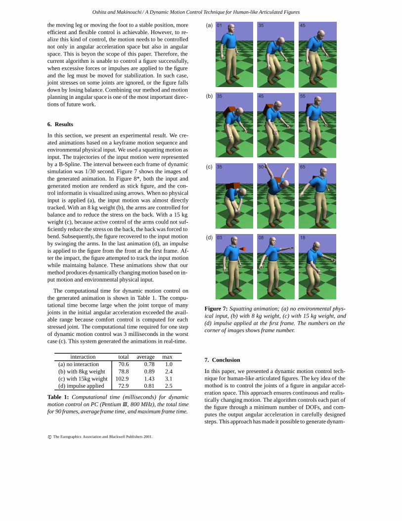
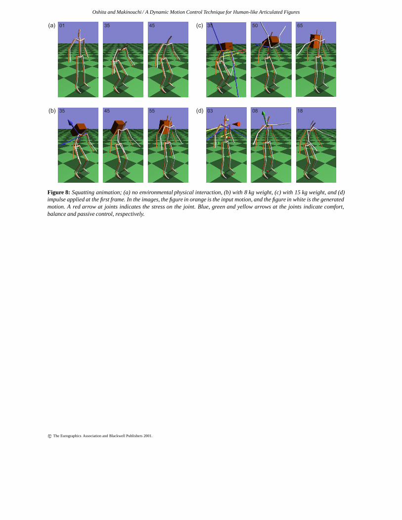
In this section, we present an experimental result. We cre-ated animations based on a keyframe motion sequence andenvironmental physical input. We used a squatting motion asinput. The trajectories of the input motion were representedby a B-Spline. The interval between each frame of dynamicsimulation was 1/30 second. Figure 7 shows the images ofthe generated animation. In Figure 8*, both the input andgenerated motion are renderd as stick figure, and the con-trol informatin is visualized using arrows. When no physicalinput is applied (a), the input motion was almost directlytracked. With an 8 kg weight (b), the arms are controlled forbalance and to reduce the stress on the back. With a 15 kgweight (c), because active control of the arms could not suf-ficiently reduce the stress on the back, the back was forced tobend. Subsequently, the figure recovered to the input motionby swinging the arms. In the last animation (d), an impulseis applied to the figure from the front at the first frame. Af-ter the impact, the figure attempted to track the input motionwhile maintaing balance. These animations show that ourmethod produces dynamically changing motion based on in-put motion and environmental physical input.
The computational time for dynamic motion control onthe generated animation is shown in Table 1. The compu-tational time become large when the joint torque of manyjoints in the initial angular acceleration exceeded the avail-able range because comfort control is computed for eachstressed joint. The computational time required for one stepof dynamic motion control was 3 milliseconds in the worstcase (c). This system generated the animations in real-time.
interaction total average max(a) no interaction 70.6 0.78 1.0(b) with 8kg weight 78.8 0.89 2.4(c) with 15kg weight 102.9 1.43 3.1(d) impulse applied 72.9 0.81 2.5
Table 1: Computational time (milliseconds) for dynamicmotion control on PC (Pentium III, 800 MHz), the total timefor 90 frames, averageframe time, and maximum frame time.
(a)
(b)
(c)
(d) 08 1803
50 6535
35 45 55
35 4501
Figure 7: Squatting animation; (a) no environmental phys-ical input, (b) with 8 kg weight, (c) with 15 kg weight, and(d) impulse applied at the first frame. The numbers on thecorner of images shows frame number.
7. Conclusion
In this paper, we presented a dynamic motion control tech-nique for human-like articulated figures. The key idea of themothod is to control the joints of a figure in angular accel-eration space. This approach ensures continuous and realis-tically changing motion. The algorithm controls each part ofthe figure through a minimum number of DOFs, and com-putes the output angular acceleration in carefully designedsteps. This approach has made it possible to generate dynam-
c The Eurographics Association and Blackwell Publishers 2001.
Oshita and Makinouchi / A Dynamic Motion Control Technique for Human-like Articulated Figures
ically changing motion in real-time. In experiments, our sys-tem successfully generated chainging motions in response tothe weight of a load and an external impulse.
As discussed in section 5.3.4, an important future researchgoal is to combine the current tracking control techniquein angular acceleration space with a dynamic motion plan-ning technique in angular space. In addition, we are goingto introduce a more realistic muscle strength model 9. Us-ing the strength model, animation accounting for the musclestrength of the character will be generated.
Physically based approaches are yet to be widely adoptedin computer games. However, such applications require dy-namically and realistically changing motion, otherwise arelimited to replaying motion sequences created in advance.We believe that the proposed technique will break the limi-tations of physically based approaches.
Acknowledgements
The work was partially supported by the Grant-in-Aid forScientific Research (10308012) from the Ministry of Educa-tion, Culture, Sports, Science and Technology of Japan.
References
1. David Baraff, and Andrew Witkin. Physically BasedModeling: Principles and Practice. SIGGRAPH ’97Course Notes, 1997.
2. Ronan Boulic, Ramon Mas-Sanso, and Daniel Thal-mann. Complex Character Positioning Based on aCompatible Flow Model of Multiple Supports. IEEETransactions on Visualization and Computer Graphics,3(3):245–261, July-September 1997.
3. Armin Bruderlin, and Thomas W. Calvert. Goal-Directed, Dynamic Animation of Human Walking.Computer Graphics (SIGGRAPH ’89 Proceedings),23(3):233–242, 1989.
4. Roy Featherstone. Robot Dynamics Algorithms.Kluwer, 1987.
5. Jessica K. Hodgins, and Nancy S. Pollard. AdaptingSimulated Behaviors For New Characters. SIGGRAPH’97 Proceedings, pages 153–162, 1997.
6. Jessica K. Hodgins, Wayne L. Wooten. David. C. Bro-gan, and James F. O’Brien. Animating Human Ath-letes. SIGGRAPH ’95 Proceedings, pages 71–78, 1995.
7. HyeongseokKo, and Norman I. Badler. Animating Hu-man Locomotion with Inverse Dynamics. IEEE Com-puter Graphics and Applications, 16(2):50–59, 1996.
8. Evangelos Kokkevis, Dimitris Metaxas, and Norman I.Badler. User-Controlled Physics-Based Animation forArticulated Figures. Proceedings of Computer Anima-tion ’96, 1996.
9. Taku Komura, Yoshihisa Shinagawa, and Tosiyasu L.Kunii. Creating and retargeting motion by the muscu-loskeletal human body model. The Visual Computer,16:254–270, 2000.
10. Jehee Lee, and Sung Youg Shin. A Hierarchical Ap-proach to Interactive Motion Editing for Human-likeFigures. SIGGRAPH ’99 Proceedings, pages 39–48,1999.
11. Philip Lee, Susanna Wei, Jianmin Zhao, and Norman I.Badler. Strength Guided Motion. Computer Graphics(SIGGRAPH ’90 Proceedings), 24(3):253–262, 1990.
12. Matthew Moore, and James Wilhelms. Collision Detec-tion and Response for Computer Animation. ComputerGraphics (SIGGRAPH ’88 Proceedings), 22(3):289–298, 1988.
13. Abhilash K. Pandya, James C. Maida, Ann M.Aldridge, Scott M. Hasson, and Barbara J. Woodford.The Validation of a Human Force Model To PredictDynamic Forces Resulting From Multi-Joint Motions.Technical Report 3206, NASA, Houston, Texas, 1992.
14. Zoran Popovic, and Andrew Witkin. Physically BasedMotion Transformation. SIGGRAPH ’99 Proceedings,pages 11-20, 1999.
15. Charles Rose, Brian Guenter, Bobby Bodenheimer, andMichael F. Cohen. Efficient Generation of MotionTransitions using Spacetime Constraints. SIGGRAPH’95 Proceedings, pages 147-154, 1995.
16. Seyoon Tak, Oh-young Song, and Hyeong-Seok Ko.Motion Balance Filtering. Computer Graphics Forum,19(3):435–446, 2000.
17. Deepak Tolani, Ambarish Goswami, and Norman I.Badler. Real-time inverse kinematics techniques for an-thropomorphic limbs. Graphical Models, 62:353-388,2000.
18. Michiel van de Pann. Parameterized Gait Synthe-sis. Computer Graphics and Applications, 16(2):40–49, March 1996.
19. M. W. Walker, and D. E. Orin. Efficient DynamicComputer Simulation of Robotic Mechanisms. Jour-nal of Dynamic Systems, Measurement, and Control,104:205–211, September 1982.
20. Andrew Witkin, and Michael Kass. Spacetime Con-straints. Computer Graphics (SIGGRAPH ’88 Proceed-ings), 22(4):159-168, 1988.
21. Victor B. Zordan, and Jessica K. Hodgins. Trackingand Modifying Upper-body Human Motion Data withDynamic Simulation. Computer Animation and Simu-lation ’99 (Proceedings of Eurographics Workshop onAnimation and Simulation ’99), 1999.
c The Eurographics Association and Blackwell Publishers 2001.
Oshita and Makinouchi / A Dynamic Motion Control Technique for Human-like Articulated Figures
(a) (c)
(b) (d)
35 45
35 45 55
01 50 6535
08 1803
Figure 8: Squatting animation; (a) no environmental physical interaction, (b) with 8 kg weight, (c) with 15 kg weight, and (d)impulse applied at the first frame. In the images, the figure in orange is the input motion, and the figure in white is the generatedmotion. A red arrow at joints indicates the stress on the joint. Blue, green and yellow arrows at the joints indicate comfort,balance and passive control, respectively.
c The Eurographics Association and Blackwell Publishers 2001.