a failure-tolerant canopen system for marine automation ... · pdf fileapplication of that...
TRANSCRIPT

A Failure-Tolerant CANopen System for Marine Automation SystemsK. Etschberger, R. Hofmann, A. Neuner, U. Weissenrieder, B. Wiulsroed
AbstractCANopen-based communication also becomes popular for failure-tolerant systems. A typicalapplication of that type is the area of marine automation systems, e.g. ship alarm, monitoringand control systems in any kind of ships like product carriers, container ships, passengervessels, ferries and cargo ships (Fig. 1) . The main rule to be met in that type of application is,that the system must tolerate at least one arbitrary single component failure. This implies thata general redundant system configuration, including the communication system, has to beprovided to fulfill the requirements of a failure-tolerant system.
This article describes a CANopen-based communication system that fulfills the requirementsof a failure-tolerant system. It was developed by IXXAT Automation for the Norwegian shipautomation systems supplier Kongsberg Norcontrol. The system already operates verysuccessfully in many applications. The implemented system concept is now established as thebasis for a CANopen-based standard in ship automation (CiA SIG Maritime Electronics).
IntroductionToday, modern ships are multifunctional plants with a number of process segments like powermanagement, engines and generators, cargo pumps and valves, ballast, bunker and cargotanks. This requires the access of up to thousands of I/O-points per process segment. Largescale systems may comprise up to 20.000 I/O-points. The large amount of data and varioussystem functions makes it necessary to implement this type of system in form of ahierarchical and modular structured architecture with decentralized intelligence. To facilitatedata collection, similarly to other fields of automation, an appropriate data communicationsystem is required.
Fig. 1: Monitoring and control of automation subsystems in large scale systems may comprise20.000 of I/O-points. Photo: Kongsberg Norcontrol (first; Berge Nord, second & third; Mainswitchboard outside & inside)
In addition to common requirements such as reasonable costs, ship automation systems mustalso satisfy increased safety conditions as claimed by the registration procedures of thedifferent classification societies.
Since the data communication model of modern automation systems takes a major part ofsuch systems, they need to meet the safety requirements as well.
Therefore the data communication system has to be failure-tolerant, too. Besides the safetyrequirements further increased demands result from the harsh environment and the highreliability demands of the ship application.
The following introduces the system concept of the implemented ship automation system,based on an extension of the CANopen standard. CANopen was selected due to its uniquefeatures, like:
• Based on the proven, robust physical and data link of CAN, the data communicationsystem provides high reliability, high error tolerance and error detection capability [1]
• Microcontrollers with integrated CAN-controllers make a very cost effectiveimplementation of the network connectivity possible
• With CANopen an already widely established and supported standard is available,which provides a very sophisticated solution for implementation of distributedautomation systems. It provides standard communication features according to theproducer-consumer model as well as the client-server-model of communication,network management and system services and a standardized method for thedescription of devices [1], [2], [3], [4],[5].
• The extension of the existing CANopen standard according to the specificrequirements of a failure-tolerant communication are straightforward
System Structure and System Components
Fig. 2 shows a typical system structure of the NORCONTROL ship automation system.
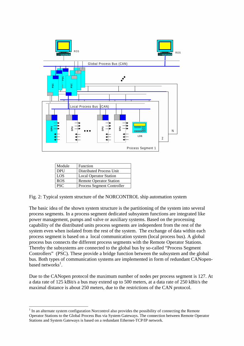
Module FunctionDPU Distributed Process UnitLOS Local Operator StationROS Remote Operator StationPSC Process Segment Controller
Fig. 2: Typical system structure of the NORCONTROL ship automation system
The basic idea of the shown system structure is the partitioning of the system into severalprocess segments. In a process segment dedicated subsystem functions are integrated likepower management, pumps and valve or auxiliary systems. Based on the processingcapability of the distributed units process segments are independent from the rest of thesystem even when isolated from the rest of the system. The exchange of data within eachprocess segment is based on a local communication system (local process bus). A globalprocess bus connects the different process segments with the Remote Operator Stations.Thereby the subsystems are connected to the global bus by so-called “Process SegmentControllers” (PSC). These provide a bridge function between the subsystem and the globalbus. Both types of communication systems are implemented in form of redundant CANopen-based networks1.
Due to the CANopen protocol the maximum number of nodes per process segment is 127. Ata data rate of 125 kBit/s a bus may extend up to 500 meters, at a data rate of 250 kBit/s themaximal distance is about 250 meters, due to the restrictions of the CAN protocol.
1 In an alternate system configuration Norcontrol also provides the possibility of connecting the RemoteOperator Stations to the Global Process Bus via System Gateways. The connection between Remote OperatorStations and System Gateways is based on a redundant Ethernet-TCP/IP network.
iRIO
RIO
RIO
RIO
LOS
N
iRIO
RIO
RIO
RIO
LOS
2
PS
C
PS
C
PS
C
PS
C
PS
C
PS
CiD
PU
DP
U
DP
U
DP
U
LOS
Local Process Bus (CAN)
Process Segment 1
Global Process Bus (CAN)
ROS ROS

Next a description of the different system components is given:
The Distributed Processing Units
The physical process interfacing and the remote processing such as monitoring and control ofthe subsystem are provided by means of Distributed Processing Units (DPU)
DPUs are available in different versions in form of digital and analogue input and outputmodules of different data width (16/32 bits) for digital modules, respectively different numberof channels (8/16) in case of analogue modules. Specific system functions are provided bymeans of dedicated DPUs like units for Generator Control & Protection. Fig. 3 shows a DPUfor Analogue Inputs.
Fig. 3: DPU for 16 channel Analogue Input (Photo: NORCONTROL)
DPU modules are based on the Infineon C167 microcontroller with two CAN interfaces. Themodules provide a standard CANopen interface [6] and are completely configurable via theCAN bus. Due to their rugged design they may be used directly in the harsh environment of aship’s machine room or directly mounted onto the engines. The modules boot managersoftware allows updating of the module software via the CAN bus. Module configuration datais stored on flash memory or EEPROM, respectively. With each power-up the boot managerperforms a self-test routine. For testing purposes each module furthermore provides asimulation mode, which can be activated via the CAN bus. Access to module configurationparameters is password protected.
In addition to the process interfacing function of normal DPUs, the so-called “IntelligentDistributed Processing Units” provide data processing capability based on programmablelogic functions. These modules are also able to operate as so-called “MMI-Server” for simpleoperator interfaces (LOS) (will be explained later).
The Remote Operator Station (ROS)
The PC/Windows NT-based Remote Operator Station (ROS) provides supervisory controland monitoring function for the system including a sophisticated graphical man-machineinterface (MMI). A ROS is connected to the CAN bus via an intelligent CAN Interface board(IXXAT Automation). This interface provides the complete standard CANopen master

functionality including several additional network and system services in form of a Windows-NT DLL for the PC-based CAN-Interface-Server (CIS). The additional network functionscomprise system configuration, controlling the system master determination process, MMIscanning, SDO management function and provision of a global system time. These functionswill be explained later.
The CAN-Interface-Server initializes the network after power up and provides a datainterface to the remote modules by means of a data base. Via this data base the different ROSclient applications have access to the remotely collected data of the system. A further functionof the CIS is the provision of a sophisticated test and simulation interface.
In connection with the DPU’s simulation mode it is possible to facilitate system installation.
The Local Operator Station (LOS)
Main purpose of the LOS devices (Local Operator Station) (Fig. 4) is to enable local access tothe intelligent DPUs for inspection of process variables, local operation or process equipment,simulation of input/output signals, adjustment of parameters and inspection of the built-indiagnosis. In small system configurations without a Remote Operator Station, the LOS can beused as the main operator station.
LOS devices may be stationary mounted or dynamically inserted into the communicationsystem by a service technician. LOS devices itself are only able to read the keyboard anddisplay messages on the LC-display. Accessing a DPU module is coordinated by an MMI-server. The MMI client-server relationship will be explained later.
Fig. 4: Low Cost Operator Station (Photo: Norcontrol)
Transmission of Process Data
According to the CANopen standard the transmission of real-time or process data is based onso-called “Process Data Objects” (PDOs). This type of communication objects provide a veryefficient usage of the available transmission bandwidth, since it is based directly on the OSI-layer-2 transmission protocol. Within one frame up to 8 bytes of data may be transmitted.
PDO communication works according to the producer-consumer model. This means that atransmitted PDO is available to any other nodes in the network. PDOs are identified by aunique 11-bit message identifier. The meaning and assembling of the data transmitted withina PDO is described in a “Device´s Object Dictionary”.To extend the number of items to be distinguished, a multiplexed usage of PDOs wasintroduced. To accomplish this, the first two data bytes of the PDO data field are used as a“tag” for specifying the following data. This allows to transmit up to 65 536 different itemswith only one PDO or CAN-identifier, respectively2. The main usage of tagged data is thetransmission of process variables of different types. The transmission of PDOs occurs event-controlled (“asynchronous PDO”) with a maximum data rate of 10 messages/sec for a PDO.Normal PDOs for transmitting of direct I/O data use CAN-identifiers according to DS 401(Default-PDOs), multiplexed PDOs use specific identifiers based on the module-ID. I/O-modules generally use up to four default PDOs, two multiplexed Transmit-PDOs anddependent of the module type a different number of multiplexed Receive-PDOs.
Transmission of Parameter and Diagnostic Data
A client-server communication channel between two devices may be established by means ofCANopen Service Data Objects (SDOs).
This type of communication is used to access the Object Dictionary of a device e.g. forconfiguration of device parameters, reading of diagnostic data, triggering of device functionsor downloading of a software update to a device. An Object Dictionary Entry is specified byits 16-bit index and 8-bit subindex. Since the SDO-protocol supports fragmentation, thenumber of bytes transmitted is practically unlimited.
Network and System Management
As an essential part of any distributed system, CANopen provides services for network andsystem management. Typically, network management functions support the boot-up of anetwork3 and provide node guarding. System management comprises standardized emergencymessaging, system-wide time synchronization, configuration services and the SDO-managerfacility.
In the Norcontrol system the system managment also provides a NMT scanning function. Thisfunction cyclically scans the network for new nodes connected to the network, identifies newnodes and checks the configuration parameter of the node against the data stored in a systemdata base. For checking of the validity of device parameters, only a specified object dictionaryentry has to be checked. This entry contains date and time of the last parameterization and ischecked against the data of the system data base. If the data does not match, the device will beparameterized automatically with the configuration data stored in the data base. Using thismethod, plug-and-play of devices is provided4.
2 Later the principle of PDO multiplexing was introduced in generalized form also into the CANopen-standardDS 301 Annex A, in form of the so-called “Multiplexed PDO”
3 In version 3.0 of DS 302 a standardized boot-up procedure will be specified, which provides plug and playcapability
4 Prerequisite for this is the prior setting of data rate and node-ID. This usually is performed by means of aservice tool in a 1:1 connection to the module using LMT services.

For node guarding, a network management instance (NMT master) cyclically polls any nodein the network to check if nodes still are able to communicate5. With the CANopen nodeguarding protocol also a node checks if the NMT-master still is alive.
The configuration of node number and setting of the baud rate via the CAN-bus is supportedby means of the CANopen LMT services and protocols6. Therefore setting of DIP-switches,which is not very appropriate in the environment of ship automation, is not necessary.
Another very important feature of a CANopen-based system are standardized emergencymessages. By means of an emergency message, a device may inform any other node about theoccurrence and reason of a device-internal failure or error condition.
To provide a system-wide synchronized time, CANopen provides a high resolution timeprotocol. Therefore, a synchronization server provides a high priority synchronizationmessage, followed by a second message which provides the exact point of time when thesynchronization message was sent. With this information, the other modules are able tosynchronize their local time reference with high accuracy to the system wide time reference.In the Norcontrol system the system-wide time reference is used for analyzing of alarmmessages, issued by the different intelligent nodes distributed in the system. Thereby, acrossthe network a maximum time difference of less than 1 ms can be provided, includingtransferring of the time messages across the process segment controllers.
In the Norcontrol system also another option of a CANopen system, the SDO manager facilityhas been implemented. This facility provides to the system the capability for dynamicestablishment of SDO-channels between devices. This feature allows to operate several LOSdevices independently on the same network and to use the provided MMI server facility of asystem manager device by the Local Operator Stations.
A node which provides the NMT master, SDO manager and optional system configurationcapability is called a “CANopen Manager” according to the CANopen terminology. In Fig. 5the main additional functions of a CANopen or system manager, as implemented in theNorcontrol system is shown. The system manager function may be executed by any one of theROS, PSC or LOS devices. With respect to the system manager function, the different devicetypes have different priority classes, with a ROS having the highest. Since at any time, onlyone node is allowed to perform as CANopen manager, a “Master Determination Process” isrequired.Since failure of the active system manager would have serious impact on the datacommunication system, the system master functionality has to be provided in redundant form.If the active CANopen manager fails, this function is automatically switched to another nodewhich is able to perform system management. This process is called “Flying Master Process”and will be described later.
5 An alternative method according to CANopen Specification DS 301, Version 4 is based on the so-called“heartbeat” message transmission. Thereby the nodes cyclically transmit a “heartbeat”-message.6 In DSP 305, Version 1 the equivalent services are called Layer Setting Services (LSS )

Fig. 5: Additional communication-related functions of system managementcapable devices (ROS, PSC, LOS)
Redundancy Concept
The general requirement for single failure tolerance in ship automation systems means, thatnot only major system components like pumps or valves have to be provided twice, but alsorequires a redundant data communication system. Therefore, the Norcontrol datacommunication system provides two pairs of CAN bus line with a system manager on eachbus possible.
As a major measure, the communication ability of each device of a network is monitoredcontinuously by means of the CANopen life guarding mechanism7. According to thisprotocol, the NMT master instance cyclically polls the communication status of each deviceafter expiration of a predefined “guard time”. The device (NMT slave instance) has to respondwithin the “node life time”. If the device fails to respond within that time, the NMT masterwill indicate a “node guarding event” to its application. On the other hand, if a device doesnot receive a status request during its “life time” from the NMT master, the NMT slave issuesa “life guarding event” to its application. A typical value for the guard time is 1 second.
For transmission of PDOs the following rules apply:
• PDO transmitting devices send a PDO on both CAN buses with the same COB-identifier and data tag. To secure the transmission of both PDOs in the same timewindow, the time of transmission of a PDO is continuously watched. If thetransmission of a certain PDO on a bus line is delayed more than a maximumallowable time interval against the transmission on the other line, the transmitting
7 Alternatively CANopen, Version 4 respectively SIG Maritime Electronics specifies a heartbeat protocol forlife guarding between a heartbeat producer and heartbeat consumers.
NMT-Master
System TimeProducer
Flying MasterCapability
NMT Scanner
MMI Scanner
SDO-Manager
EmergencyConsumer/Producer
SyncProducer
ConfigurationManager(only ROS)
PDO queue of the other bus line is copied into the delayed queue. Synchronizing ofthe transmit PDO queues also occurs in case of a transmit queue overrun. Any queueresynchronization is signaled on the bus by transmission of an emergency message.
• PDOs are received on both CAN-buses. The received data is stored into thecorresponding Object Dictionary entries.
Emergency messages are handled like PDOs.
Data transmission via SDO channels is independent on both CAN lines.
Since the standard object dictionary of the devices has usually only one set of SDO client andserver entries for identifiers used by the SDOs, the redundant bus architecture provides anown set of client and server SDO entries for each side.
Therefore the dynamic establishment of SDO channels works without interfering with theother CAN line.
Determination of the active CANopen manager
In a system, it is possible to have more than one manager-capable devices like ROS, PSC andLOS in a network. It is therefore necessary to provide a process, by which automatically oneof the manager-capable devices becomes the active system manager. Also, in case of a failureof the currently active system manager an automatic determination of another manager-capable device has to be performed. Fig. 6 shows the master determination process at a ROSdevice.
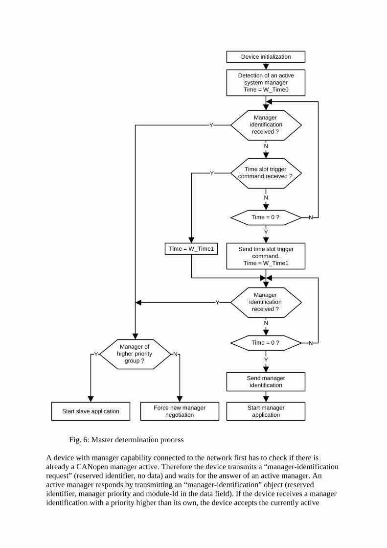
Fig. 6: Master determination process
A device with manager capability connected to the network first has to check if there isalready a CANopen manager active. Therefore the device transmits a “manager-identificationrequest” (reserved identifier, no data) and waits for the answer of an active manager. Anactive manager responds by transmitting an “manager-identification” object (reservedidentifier, manager priority and module-Id in the data field). If the device receives a manageridentification with a priority higher than its own, the device accepts the currently active
Device initialization
Detection of an activesystem managerTime = W_Time0
Manager identification
received ?
Time slot triggercommand received ?
Time = 0 ?
Send time slot triggercommand.
Time = W_Time1
Manageridentificationreceived ?
Time = 0 ?
Send manageridentification
Start managerapplication
Time = W_Time1
Manager ofhigher priority
group ?
Force new managernegotiation
Start slave application
YY
N
N
Y
N
N
N
Y
Y
Y
N
master and starts its slave application. If the priority of the currently active manager is lower,the newly connected device forces a new manager determination process by transmitting aNMT reset communication command with a module ID equal to 0.
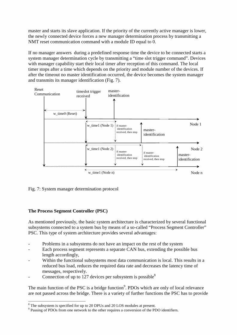
If no manager answers during a predefined response time the device to be connected starts asystem manager determination cycle by transmitting a “time slot trigger command”. Deviceswith manager capability start their local timer after reception of this command. The localtimer stops after a time which depends on the priority and module number of the devices. Ifafter the timeout no master identification occurred, the device becomes the system managerand transmits its manager identification (Fig. 7).
Fig. 7: System manager determination protocol
The Process Segment Controller (PSC)
As mentioned previously, the basic system architecture is characterized by several functionalsubsystems connected to a system bus by means of a so-called “Process Segment Controller”PSC. This type of system architecture provides several advantages:
- Problems in a subsystems do not have an impact on the rest of the system- Each process segment represents a separate CAN bus, extending the possible bus
length accordingly,- Within the functional subsystems most data communication is local. This results in a
reduced bus load, reduces the required data rate and decreases the latency time ofmessages, respectively.
- Connection of up to 127 devices per subsystem is possible8
The main function of the PSC is a bridge function9. PDOs which are only of local relevanceare not passed across the bridge. There is a variety of further functions the PSC has to provide
8 The subsystem is specified for up to 20 DPUs and 20 LOS modules at present.9 Passing of PDOs from one network to the other requires a conversion of the PDO identifiers.
Node 1
Node 2
Node n
timeslot triggerreceived
w_time1 (Node 1)
w_time1 (Node 2)
w_time1 (Node n)
master-identification
master-identification
master-identification
if master- identificationreceived, then stop
if master- identificationreceived, then stop
if master- identificationreceived, then stop
ResetCommunication
w_time0 (Reset)
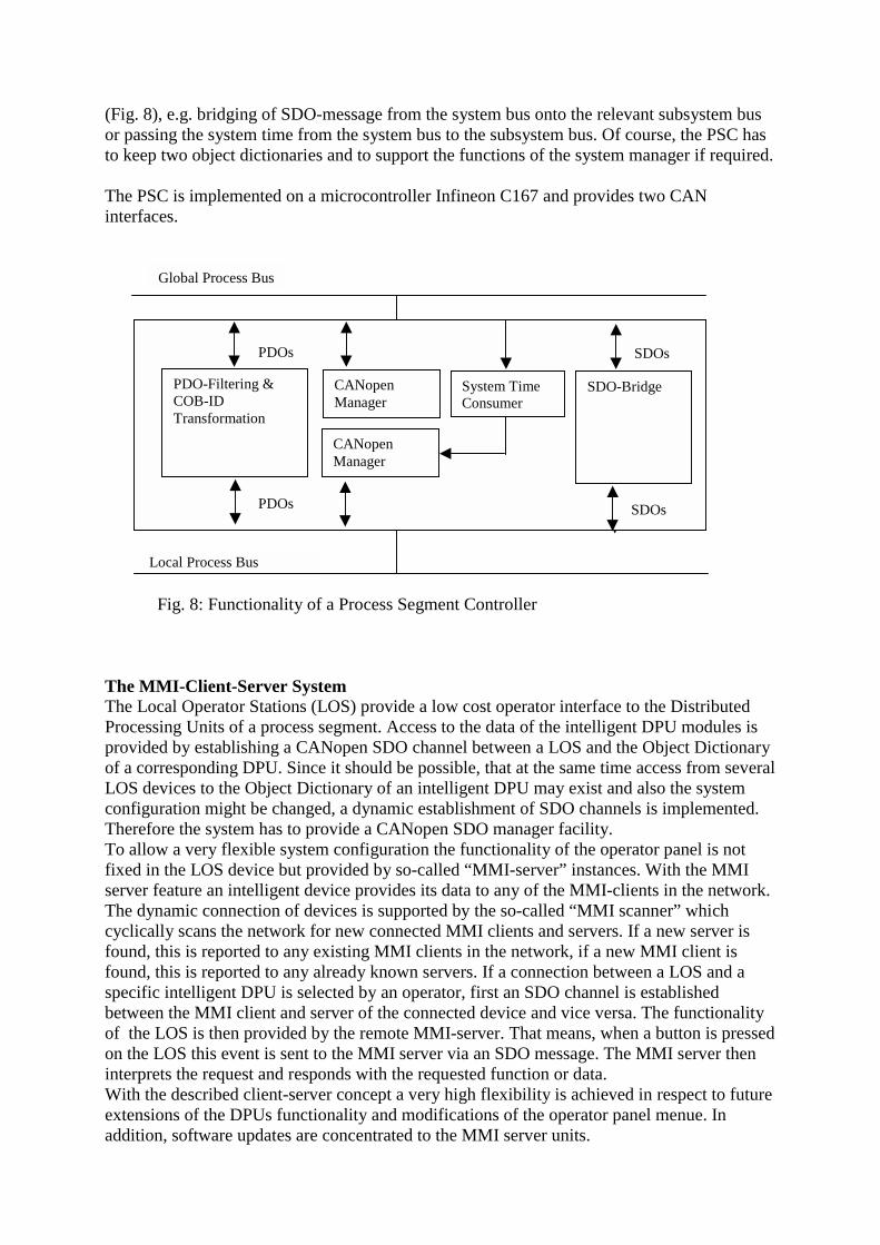
(Fig. 8), e.g. bridging of SDO-message from the system bus onto the relevant subsystem busor passing the system time from the system bus to the subsystem bus. Of course, the PSC hasto keep two object dictionaries and to support the functions of the system manager if required.
The PSC is implemented on a microcontroller Infineon C167 and provides two CANinterfaces.
Fig. 8: Functionality of a Process Segment Controller
The MMI-Client-Server SystemThe Local Operator Stations (LOS) provide a low cost operator interface to the DistributedProcessing Units of a process segment. Access to the data of the intelligent DPU modules isprovided by establishing a CANopen SDO channel between a LOS and the Object Dictionaryof a corresponding DPU. Since it should be possible, that at the same time access from severalLOS devices to the Object Dictionary of an intelligent DPU may exist and also the systemconfiguration might be changed, a dynamic establishment of SDO channels is implemented.Therefore the system has to provide a CANopen SDO manager facility.To allow a very flexible system configuration the functionality of the operator panel is notfixed in the LOS device but provided by so-called “MMI-server” instances. With the MMIserver feature an intelligent device provides its data to any of the MMI-clients in the network.The dynamic connection of devices is supported by the so-called “MMI scanner” whichcyclically scans the network for new connected MMI clients and servers. If a new server isfound, this is reported to any existing MMI clients in the network, if a new MMI client isfound, this is reported to any already known servers. If a connection between a LOS and aspecific intelligent DPU is selected by an operator, first an SDO channel is establishedbetween the MMI client and server of the connected device and vice versa. The functionalityof the LOS is then provided by the remote MMI-server. That means, when a button is pressedon the LOS this event is sent to the MMI server via an SDO message. The MMI server theninterprets the request and responds with the requested function or data.With the described client-server concept a very high flexibility is achieved in respect to futureextensions of the DPUs functionality and modifications of the operator panel menue. Inaddition, software updates are concentrated to the MMI server units.
SDOs
Global Process Bus
PDO-Filtering &COB-IDTransformation
CANopenManager
CANopenManager
System TimeConsumer
SDO-Bridge
PDOs
PDOs
SDOs
Local Process Bus
SDOs
SummaryWith the developed automation system based on CAN/CANopen, a very cost effective,modular system of high flexibility and capability is available, which also fulfills the specificsafety requirements of ship automation. The system already is in operation successfully inmany applications.
The underlying hierarchical system architecture and partitioning of the system into severalsubsystems provides important advantages with respect to reduced failure interaction, reducedbus load and increased maximum number of devices.
CAN and CANopen has been proven to be a very suitable platform also for theimplementation of a very sophisticated, safety relevant communication system. The onlynecessary extension of the standard was the introduction of a mechanism for automatic masterdetermination according to the “flying master” principle. In the data communication systemalso the optional management functions according to the framework for programmabledevices [3] like SDO- and configuration management as well as provision of a system-widehigh resolution time reference have been implemented successfully. The developed systemsolution will be the main input for the ongoing development of an application standard by theSIG Maritime Electronics.
Literature[1] K. Etschberger, Controller-Area-Network, Grundlagen, Protokolle, Bausteine,
Anwendungen. Hanser-Verlag 2000, ISBN3-446-19431-2(English Edition available Q4/2000)
[2] CIA DS 301: CANopen Communication Profile for Industrial Applications, Version4.01, June 2000
[3] CIA DS 302: Framework for Programmable CANopen Devices, Version 3.0, June2000
[4] CIA DS 401: CANopen Device Profile for I/O Modules, Version 2.0, December 1999[5] CIA DSP 305: Layer Setting Services and Protocol, Version 1.0, May 2000[6] IXXAT, CANopen Master/Slave Software Description, May 2000
AuthorsProf. Dr.-Ing. K. Etschberger, R. Hofmann, A. Neuner, U. Weissenrieder, IXXATAutomation, Leibnizstraße 15, 88250 Weingarten, www.ixxat.deB. Wiulsroed, Kongsberg Norcontrol, P.O Box 1009, N-3194 Horten, Norway,www.norcontrol.no