a fault-tolerant and deadlock-free routing protocol in 2d meshes
TRANSCRIPT

A Fault-Tolerant and Deadlock-Free RoutingProtocol in 2D Meshes Based on
Odd-Even Turn ModelJie Wu, Senior Member, IEEE
Abstract—We propose a deterministic fault-tolerant and deadlock-free routing protocol in two-dimensional (2D) meshes based on
dimension-order routing and the odd-even turn model. The proposed protocol, called extended X-Y routing, does not use any virtual
channels by prohibiting certain locations of faults and destinations. Faults are contained in a set of disjointed rectangular regions called
faulty blocks. The number of faults to be tolerated is unbounded as long as nodes outside faulty blocks are connected in the 2D mesh
network. The extended X-Y routing can also be used under a special convex fault region called an orthogonal faulty block, which can
be derived from a given faulty block by activating some nonfaulty nodes in the block. Extensions to partially adaptive routing, traffic and
adaptivity-balanced using virtual networks, and routing without constraints using virtual channels and virtual networks are also
discussed.
Index Terms—Deadlock-free routing, deterministic routing, fault models, fault tolerance, turn models, virtual channels.
�
1 INTRODUCTION
THE direct network is a popular means to constructmulticomputers, where a set of channels are used to
connect each processor (node) to limited neighbors. In amulticomputer system, routing algorithms providemechanisms for communication between nodes. The per-formance of such a system depends heavily on theefficiency of routing algorithms. Routing algorithms areeither deterministic or adaptive. Deterministic routing usesonly one path to route packets from a source to adestination, while adaptive routing makes use of manydifferent routes. Most commercial systems use deterministicrouting because of its deadlock freedom and ease ofimplementation.
Dimension-order routing is a commonly used determi-
nistic routing algorithm in mesh-connected multicomputers
which include meshes, tori (meshes with wraparound
connections), and hypercubes. Among commercial multi-
computers and research prototypes, IBM Blue Gene [11]
uses a 32� 32� 32 3D mesh. Alpha 21364’s multiple
processor network [19] employs a 2D torus, and SGI Origin
[1] adopts a variation of the hypercube structure. In
dimension-order routing, a routing packet is routed in one
dimension at a time (the offset between the source and
destination nodes is reduced to zero along that dimension).
X-Y routing is an example of dimension-order routing used
in two-dimensional (2D) meshes and tori. In X-Y routing,
the packet is routed first in the x dimension and then in the
y dimension. Unfortunately, X-Y routing is not fault-tolerant and cannot tolerate even a single fault.
Designing a routing protocol that is both fault-tolerantand deadlock-free poses a major challenge. The wormholeswitching technique used in the latest generation of multi-computers is subject to deadlock more than packet switch-ing. In addition, wormhole switching tends to supportrouting with less fault tolerance. Wormhole routing dividesa message into packets and packets into flits. It then routesflits through the network in a pipeline fashion. When theheader flit reaches a node that has no output channelavailable, all of the flits are blocked where they are (inplace). A deadlock occurs when some packets fromdifferent messages cannot advance toward their destina-tions because the channels requested by them are notavailable. All the packets involved in a deadlockedconfiguration are blocked forever. Fig. 1 shows a deadlocksituation in a 2D mesh. Boxes represent flit buffers and thenumber inside each buffer indicates the destination node id.Solid arrows represent the channel requested by the headflit in the buffer. Cycles represent nodes (and theirswitches). Clearly, the packets intended for 1 are blockedby the ones intended for 2. The ones intended for 2, in turn,are blocked by the ones for 3, and the ones for 3 by the onesfor 4. Finally, the packets intended for 4 are blocked by theones for 1 to complete a cyclic waiting queue—a deadlocksituation occurs, where competing resources are channels(instead of nodes and switches).
Deadlock avoidance is a commonly used approach inwhich channels are granted to a packet in such a way that arequest never leads to a deadlock. To achieve fault tolerance,faults arenormally contained in a set ofdisjointed rectangularregions called faulty blocks. Each faulty block may includesome nonfaulty nodes. The convexity of faulty blocksfacilitates a simple design of deadlock-free routing. It isassumed that fault distribution is not known and only the
1154 IEEE TRANSACTIONS ON COMPUTERS, VOL. 52, NO. 9, SEPTEMBER 2003
. The author is with the Department of Computer Science and Engineering,Florida Atlantic University, Boca Raton, FL 33431.E-mail: [email protected].
Manuscript received 17 Dec. 2001; revised 3 Oct. 2002; accepted 25 Oct.2002.For information on obtaining reprints of this article, please send e-mail to:[email protected], and reference IEEECS Log Number 115573.
0018-9340/03/$17.00 � 2003 IEEE Published by the IEEE Computer Society

boundary nodes of each faulty block know their existence. Todesign a deadlock-free routing, virtual channels [8] andvirtual networks [18] are commonly used to provide a certaindegree of routing freedom to route around a faulty block.
Ideally, a fault-tolerant and deadlock-free routing proto-col should meet the following objectives:
1. Distributed routing: The routing is distributedwithout the knowledge of the number and distribu-tion of faults.
2. Feasibility: The packet sent from the source shouldeventually reach the destination.
3. Fault tolerance: The packet should be able to bypassfaults encountered during the routing process.
4. Freedom of deadlock: Under no situation can severalpackets be involved in the deadlock situation.Ideally, the freedom of deadlock should be achievedusing a minimum number of virtual channels.
5. Short route: The packet should still be routed along ashort route if possible.
6. Reasonable fault model: The fault model should berealistic and should not be overly conservative(without disabling many nonfaulty nodes).
7. Adaptivity: The routing should be partially adaptivewhen possible.
8. Balanced traffic: Channels should be used in abalanced way to avoid possible congestion in certainareas.
Some of the objectives may conflict with each other;therefore, trade offs are needed.
The proposed fault-tolerant and deadlock-free routingprotocol in 2D meshes is based on X-Y routing and the odd-
even turn model [7], an extension to Glass and Ni’s turnmodel [14] where certain turns are prohibited to avoiddeadlock. The protocol, called extended X-Y routing, isproposed to meet objectives 1 to 5. The extended X-Yrouting is deterministic and it does not use any virtualchannels by prohibiting certain locations of faults anddestinations. The main purpose of posing such restrictionsis to better present our idea without going into messydetails of boundary situations. The protocol is firstproposed as a deterministic version, followed by anextension to the partially adaptive one. The number offaults to be tolerated is unbounded as long as nodes outsidefaulty blocks are connected in the resultant mesh network.Each faulty block is surrounded by a boundary ringconsisting of four boundary lines, one for each direction.However, the boundary line defined at the east (and west)
side of each faulty block consists of two lines: one in an evencolumn (column with an even label) and one in an oddcolumn (see Fig. 5). The faulty block is so defined that nodeson the boundary lines of a faulty block (simply calledboundary nodes) do not intersect with any other faultyblock, providing just enough flexibility for the packet tomake appropriate turns. In the absence of faults, theextended X-Y routing works like a regular X-Y routing,which routes packets along the x dimension first followedby the y dimension. When packets reach a boundary nodeof a faulty block, the boundary ring is used to route packetsaround the block.
To meet objective 6, the extended X-Y routing isextended to be applied to a special convex fault region,called an orthogonal faulty block [26], which can be derivedfrom a given faulty block after activating some nonfaultynodes in the block. The localized algorithm [10], [27], a specialtype of decentralized algorithm, is used to construct faultyblocks, orthogonal faulty blocks, and boundary lines. Tomeet objectives 7 and 8, extensions to partial adaptiverouting, traffic and adaptivity-balanced routing usingvirtual networks, and routing without constraints usingvirtual channels and virtual networks are also discussed.
The following assumptions are used in this paper:
1. Only node faults are considered and they arecontained in a set of disjointed faulty blocks definedin the paper.
2. The dynamic fault model is used; however, it isassumed that no new faults occur during a routingprocess.
3. Both the source and destination nodes are outsideany faulty block. In addition, the destination is not aboundary node of any faulty block.
4. Faults do not appear at four edges of a mesh. Inaddition, no fault appears in two columns that areadjacent to the west and east edges of the mesh.
5. There is no limit on the number of faults as long asthe 2D mesh is connected.
Note that almost all the above assumptions can berelaxed. Related to condition 1, link faults can be treated asnode faults by considering their end nodes faulty, althoughthe “inflation” of faults might occur. Since faulty blocksconverge quickly when new faults occur (or when faultynodes recover), the proposed approach can be extended tohandle dynamic faults during a routing process through acareful design. Condition 3 can be removed by using twovirtual channels, as will be shown in the extension of theproposed approach. Condition 4 is used to avoid handlingthe complex boundary situation. If condition 4 fails, eithernodes of the corresponding edge(s) are disabled andremoved from the mesh or virtual channels are introducedas used in many existing approaches [3], [23] to routearound faulty blocks that are at the edge of the mesh.
The remainder of the paper is organized as follows:Section 2 discusses related work. Section 3 providespreliminaries where the odd-even turn model is reviewed,the general methodology of localized algorithms is dis-cussed, and an extended faulty block model is introduced.Section 4 proposes the extended X-Y routing, which is afault-tolerant and deadlock-free routing protocol and uses
WU: A FAULT-TOLERANT AND DEADLOCK-FREE ROUTING PROTOCOL IN 2D MESHES BASED ON ODD-EVEN TURN MODEL 1155
Fig. 1. A deadlock situation involving four packets in a 2� 2 submesh.

no virtual channels. Section 5 extends the protocol to a2D mesh with orthogonal faulty blocks. A localizedalgorithm for the formation of orthogonal faulty blocks isalso included. Section 6 lists ideas for other possibleextensions. Section 7 concludes the paper and discussespossible future work.
2 RELATED WORK
Virtual channels [8] were first introduced to preventdeadlock and offer adaptivity in routing, rather than forfault tolerance. Normally, several virtual channels aremultiplexed across a physical channel. Duato [9] provideda general deadlock-free routing approach by introducingthe notion of escape channels. In this general approach,virtual channels are divided into two groups: one fornonminimal adaptive routing and the other (called escapechannels) for minimal, deterministic routing. Park andAgrawal [20] discussed a similar design methodology fordeadlock-free routing, but routing functions are based onthe history of channels in addition to destination informa-tion. Fleury and Fraigniaud [12] gave a comprehensivesurvey on different deadlock-free routing protocols.
Linder and Harden [18] were the first to use virtualchannels and virtual networks to achieve fault tolerance.Their method requires Oð2nÞ virtual channels for a fullyadaptive fault-tolerant routing in an n-D mesh. Usingvirtual channels has some disadvantages, for example,routers based on virtual channels require more gates andtime compared with those not based on virtual channels. Toreduce the number of virtual channels, Chien and Kim [6]introduced the planar adaptive routing which providespartial adaptivity in an n-D mesh by first dividing therouting process into a sequence of phases and thenforwarding packets in two dimensions within each phase.
Many fault-tolerant routing algorithms in 2D meshes andtori have been proposed. In Boppana and Chalasani’sapproach [3], fault regions are surrounded by either faultrings or fault chains (used when the faulty block is at theedge of a mesh). When a packet encounters a fault region, afault ring or chain is used to route the packet around theregion. Deadlock is avoided by using four virtual channelsper physical channel for dimension-order routing. Manyextensions based on Boppana and Chalasani’s approachhave been proposed [4], [5], [16], [21], [23], [24], [28]. Theseextensions try to reduce either the number of nonfaultynodes in a faulty block by considering different types offault regions or the number of virtual channels. So far, thebest results can reduce the number of virtual channels totwo or three depending on the type and distance betweenfaulty blocks used. To our knowledge, there is no deadlock-free dimension-order routing that can tolerate an unlimitednumber of faults without using virtual channels.
Glass and Ni’s fault-tolerant routing [13] in mesheswithout using virtual channels is based on the turn model[14]. However, its fault tolerance capability is limited ton� 1 in an n-D mesh, i.e., one fault in a 2D mesh. Fault-tolerant routing without using virtual channels exists fornon-dimension-order routing. For example, fault-tolerantpath-based routing [17] is based on finding a Hamiltonianpath or pseudo-Hamiltonian path in a faulty mesh or torus.
However, it is nonminimal and, unlike the faulty blockmodel, path information is difficult to maintain in alocalized way. Note that routing that allows backtrackingcan potentially tolerate an unlimited number of faults, suchas the one proposed by Suh et al. [22]. In such an approach,routing history is coded in the header to navigate therouting process.
Recently, Ho and Stockmeyer [15] proposed a newapproach to fault-tolerant routing for mesh-connectedmulticomputers with an objective of minimizing thenumber of “turns” in each route. Instead of using therectangular faulty block model, some nonfaulty nodes aredisabled so that all the remaining nodes can be reachedthrough two rounds of dimension-order routing. Disablednodes are called sacrificial lambs and are similar to nonfaultynodes included in faulty blocks. In this approach, twovirtual channels are used. A two-approximation greedyalgorithm is proposed to find a small set of disabled nodes.
Although routers with many virtual channels are quitecommon today [19], the gain of reducing the overhead ofadditional virtual channels still exists. For example, thearbitration mechanism is simplified with a reduced numberof channels. One can envision an architecture for multi-computers similar to the Infiniband architecture [2] inwhich separated virtual channels are used for each servicelevel (different class). In such a case, more service levels canbe supported if a fault-tolerant and deadlock-free routingalgorithm is supported without additional virtual channels.
3 PRELIMINARIES
In this section, we first review the mesh topology andChiu’s odd-even turn model, which is an extension to Glassand Ni’s turn model. We then discuss the generalmethodology of localized algorithms. Finally, we introducean extended faulty block model.
3.1 2D Meshes
A two-dimensional (2D) mesh with n2 nodes has an interiornode degree of 4. Each node u has an address u: ðux; uyÞ,where ux; uy 2 f0; 1; 2; . . . ; n� 1g. Two nodes u: ðux; uyÞ andv: ðvx; vyÞ are connected if their addresses differ in one andonly one dimension, say, x; moreover, jux � vxj ¼ 1. Eachnode, except the one at the edge of a 2D mesh, has fourneighbors, one in each of four directions: east, south, west,and north.
3.2 Odd-Even Turn Model
Chiu [7] proposed an odd-even turn model, an extension toGlass and Ni’s turn model [14]. In general, deadlockavoidance tries to avoid the formation of a cycle, which isa necessary condition for deadlock. A cycle in a meshconsists of several turns. For example, SW (southwest), WN,NE, and ES turns are essential in a clockwise cycle. TheX-Y routing is made deadlock-free by prohibiting a turnfrom the y dimension to the x dimension. Specifically, fourtypes of turns are disallowed: two in a clockwise cycle andtwo in a counterclockwise cycle. The basic concept behindthe turn model is to prohibit a minimum number of turnsand, hence, increase the routing adaptivity. In general, onlyone turn is prohibited in each cycle. For example, in a
1156 IEEE TRANSACTIONS ON COMPUTERS, VOL. 52, NO. 9, SEPTEMBER 2003

positive-first turn model two types of turns are disallowed(one for each cycle), that is, the turns from the negative topositive directions. The odd-even turn model restricts thelocations where some of the turns can occur so that an EN(eastnorth) turn and an NW turn are not taken at nodes inthe same column and neither are an ES turn and an SWturn. Specifically, the odd-even turn model tries to preventthe formation of the rightmost column segment of a cycle. Chiugave two rules for turn [7]:
Rule 1. Any packet is not allowed to take an EN turn at any nodelocated in an even column and it is not allowed to take an NWturn at any node located in an odd column.
Rule 2. Any packet is not allowed to take an ES turn at any nodelocated in an even column and it is not allowed to take an SWturn at any node located in an odd column.
Fig. 2 shows these two rules on the EN, NW, ES, and SWturns. These four turns are called sensitive turns. Turnswithout restriction are called insensitive turns. A smalltriangle is placed at each sensitive turn that is permissible(as shown in Fig. 2). Forbidden turns are represented asones with dashed lines. A turn in an even (odd) column isrepresented by E (O). Basically, in an odd-even turn model,once east-bound starts, no more west-bound is allowed in therouting process. Again, four directions are defined as: East(þy), South (�x), West (�y), and North (þx). (Unlike theconvention, the north-south axis is used here as the x axis tomatch the notation used in the odd-even turn model.)
To support a minimum and partially adaptive routing ina fault-free 2D mesh, we consider a restricted zig-zag routing
based on the odd-even turn model. The zig-zag routingrepresents an adaptive and minimal routing in 2D meshes,where each hop in the routing process can be selected fromone of the two profitable dimensions (i.e., the packet willget closer to the destination at each hop). The term“restricted” comes from the fact that a turn in zig-zagrouting can only be made in a certain column. If a turn canonly be made in an odd (even) column, it is called even-(odd)restricted zig-zag routing. Routing can be divided intoEW-routing (from east to west) and WE-routing (from westto east). The case for the offset along the y dimension (�y)and the x dimension (�x) being zero is excluded since thepacket can be routed straight to the destination withoutmaking any turn. Based on the rules in the odd-even turnmodel, EW-routing follows the odd-restricted zig-zagrouting unless the odd-column-turn is in the destinationcolumn. Fig. 3a shows an EW-routing where the destinationis in the second quadrant of the source, where label “E”represents an even column. For WE routing, if thedestination is in an odd column, the even-restricted zig-zag routing is followed (see Fig. 3b for the first quadrantrouting). If the destination is in an even column, the samerule as above is followed to reach the west neighbor d0 of thedestination d. The route completes with an east hop from d0
to d (as shown in Fig. 3c for the first quadrant routing). Therouting process in the third and fourth quadrants is similarto the one in the first and second quadrants, respectively.
3.3 Localized Algorithms
In a localized algorithm [10], [27], which is a special type ofdecentralized algorithm, each processor (process) interacts
WU: A FAULT-TOLERANT AND DEADLOCK-FREE ROUTING PROTOCOL IN 2D MESHES BASED ON ODD-EVEN TURN MODEL 1157
Fig. 2. Permissible EN, NW, ES, and SW turns.
Fig. 3. Minimum and partially adaptive routing in odd-even turn model: (a) EW-routing in the second quadrant. (b) EW-routing in the first quadrant
(destination in the odd column). (c) EW-routing in the first quadrant (destination in an even column).

with others in a restricted vicinity, but nevertheless
collectively achieves a desired global objective. This type
of algorithm is useful in a system with a set of independent,
autonomous processors (processes). In general, each pro-
cessor (process) performs exceedingly simple tasks, such as
maintaining and propagating information “markers.” In
this paper, we study several localized algorithms in which
only neighbors exchange and update their markers.
3.4 Faulty Blocks
We first introduce a special faulty block model. Faulty
nodes in a 2D mesh are contained in a set of disjointed
rectangular faulty blocks. The regular faulty block model is
defined as follows: All nonfaulty nodes are safe initially. A
nonfaulty node is changed to unsafe if it has two unsafe or faulty
neighbors in different dimensions. Fig. 4 shows three sample
faulty blocks where black nodes are faulty, gray are unsafe,
and other nodes are safe. The boundary rings are shown in
boldface.In the extended faulty block model proposed in this
paper, each faulty block is surrounded by a boundary ring
consisting of four boundary lines, one for each direction.
The boundary line at the east (and west) side of the block
consists of two lines. Two faulty blocks are disjointed if the
boundary ring of one faulty block does not intersect with
the other faulty block.
Definition 1. All nonfaulty nodes are safe initially. A nonfaulty
node is changed to unsafe if:
1. It has two unsafe or faulty neighbors that are not bothin the x dimension or
2. It has an unsafe or faulty neighbor in the x dimensionand an unsafe or faulty 2-hop neighbor (neighbor’sneighbor) in the y dimension.
An extended faulty block consists of connected unsafeand faulty nodes. Note that, although both unsafe andfaulty nodes are included in faulty blocks, they are treateddifferently, as will be seen later in the orthogonal faultyblock model where certain unsafe nodes can be activated byremoving them from the blocks. The difference between theextended faulty block definition (Definition 1) and theconventional one lies in the different treatments of adjacentnodes in different dimensions. An extended faulty blockand its boundary nodes are so defined to facilitate fault-tolerant routing based on the odd-even turn model to bediscussed in the next section. It can be easily shown thatfaulty blocks in 2D meshes are disjointed rectangles. Let u:ðux; uyÞ and v: ðvx; vyÞ be two nodes in a 2D mesh, dðu; vÞ ¼jux � vxj þ juy � uyj denotes the distance between u and v.The distance between two faulty blocks A and B is definedas dðA;BÞ ¼ minu2A;v2Bfdðu; vÞg. It can be easily shown thatthe distance between any two faulty blocks, A and B, is atleast 3 along the y dimension or is at least 2 along thex dimension. Fig. 5 shows three extended faulty blocks ofthe example in Fig. 4. In the subsequent discussion, faultyblocks and extended faulty blocks are sometimes usedinterchangeably.
In the localized algorithm for safe/unsafe status (seeFig. 6), each nonfaulty node is marked either safe or unsafe.Neighbors exchange and update their markers. Eventually,connected unsafe and faulty nodes form a faulty block(which is a global objective). To facilitate the decision
1158 IEEE TRANSACTIONS ON COMPUTERS, VOL. 52, NO. 9, SEPTEMBER 2003
Fig. 4. Three examples of faulty blocks where black nodes are faulty nodes and gray nodes are nonfaulty nodes.
Fig. 5. Three examples of extended faulty blocks in Fig. 4.

process of node status, each node sends its status to its2-hop neighbors along the y dimension. It is assumed thateach node knows the status of its neighbors.
Theorem 1. Boundary nodes of a faulty block do not intersectwith any other faulty block.
Proof. Assume that node u is a boundary node of a faultyblock A, that is, it is either a 1-hop neighbor alongdimension x or a 1-hop or 2-hop neighbor alongdimension y. Assume that node u also belongs to faultyblock B. Based on the faulty block definition, faultyblocks A and B should be combined to form a singleblock. This brings a contradiction. tu
Although boundary nodes of a faulty block do notintersect with any other faulty block, boundary nodes ofdifferent faulty blocks may overlap, that is, a node can be aboundary node of more than one faulty block. Thecomplexity of the safe/unsafe status procedure, in termsof the number of rounds needed, is the maximum diameterof faulty blocks in the mesh: maxfdiamðAÞg. Since the safe/unsafe process is a localized algorithm, a faulty block can beconstructed in a decentralized way in a few rounds [26].This property supports dynamic reconfiguration of faultyblocks.
4 EXTENDED X-Y ROUTING
We propose a routing process, called extended X-Y routing,which consists of two phases, similar to a regular X-Yrouting. (That is why it still belongs to dimension-orderrouting, although the other dimension is used within eachphase to bypass faulty blocks encountered.) In phase 1, theoffset along the x dimension is reduced to zero and, inphase 2, the offset along the y dimension is reduced to zero.Assume the source and destination nodes are both safe. Lets : ðsx; syÞ and d : ðdx; dyÞ be the source and destinationnodes, respectively. �x ¼ jdx � sxj and �y ¼ jdy � syj areoffsets along dimension x and dimension y, respectively.
The extended X-Y routing provides a special implemen-tation of the requirement posed in the odd-even model and,
at the same time, supports fault-tolerant routing. Theextended X-Y routing (shown in Fig. 9) follows the regularX-Y routing (and the packet is in a “normal” mode) until thepacket reaches a boundary node of a faulty block (this blockis called the routing block). At that point, the packet is routedaround the block (and the packet is in an “abnormal” mode)clockwise or counterclockwise based on certain rules:Unlike routing in a fault-free routing, the fault-tolerantrouting protocol has to prepare for “unforeseen” situations:a faulty block encountered during the routing process. Thesolution is to route around the block without using anyforbidden turns. This is done by three means: 1) the packetshould reside in an even column when reaching a north orsouth boundary node of the routing block in phase 1. 2) Inphase 1, the packet should be routed around the west sidesince, once the packet is east-bound, it cannot be changed towest-bound later. 3) The two boundary lines, one even andone odd, offer just enough flexibility for the packet to maketurns for all situations. More specifically, during phase 1,the packet is routed around the routing block through thewest side of the block. Even columns are used to route thepacket along the x dimension (column). If the source is in anodd column, the first hop is to the west neighbor of thesource (which is in an even column). In phase 2, to routearound the routing block, odd columns (even columns) areused to perform routing along the y dimension when thepacket is east-bound (west-bound) (see Fig. 7c and Fig. 7d).The packet is routed around the routing block eitherclockwise or counterclockwise in phase 2 (see Fig. 7c andFig. 7d). Note that, during the normal mode of routing thepacket along the x or y dimension, no 180� turn is allowed.For example, the positive x direction cannot be changed tothe negative x direction.
A special case occurs when the destination is at the eastside of the routing block. In this case, when phase 1completes, the routing packet is still at the west side of therouting block, as shown in Fig. 8. The even (marked as E)boundary column of the routing block is switched to theodd (marked as O) boundary column (two subcases areshown in Fig. 8a and Fig. 8b) and, then, the packet is routed
WU: A FAULT-TOLERANT AND DEADLOCK-FREE ROUTING PROTOCOL IN 2D MESHES BASED ON ODD-EVEN TURN MODEL 1159
Fig. 6. A localized algorithm for determining safe/unsafe status.

around the block either clockwise or counterclockwise.Fig. 10 shows three routing examples ðsi; diÞ, withi 2 f1; 2; 3g, in a 10� 10 mesh with four faulty blocks F1,F2, F3, and F4. Note that, when the routing packet reaches anorthwest (NW) or southwest (SW) corner of a routingblock in phase 1, the packet goes straight, north-bound orsouth-bound, without further routing around the block (seeFig. 7a and Fig. 7b).
A fault-tolerant routing process is livelock-free if it candeliver packets from the source to destination, regardless ofthe number and location of faults. The following resultshows that the extended X-Y routing is both deadlock-freeand livelock-free in a 2D mesh where faults are contained ina set of disjointed faulty blocks.
Theorem 2. The extended X-Y routing is deadlock-free andlivelock-free.
Proof. In the routing process, all sensitive turns arepermissible, based on the results from the odd-even turnmodel [7], the extended X-Y routing is deadlock-free. Toshow the livelock-free property, we only need to showthat �x (�y) is eventually reduced to zero in phase 1(phase 2). In phase 1, �x is always reduced by one ateach step (with no 180� turn), except when the packet isrouted around a faulty block by going west. There aretwo cases of west-bound hops, one case is in the first hopfor the packet to reach an even column and the other caseoccurs when the packet is routed around a faulty block.Since the size of each faulty block is limited, the numberof west-bound hops is a finite number. In addition,although the packet may have to route around severalfaulty blocks (or several abnormal modes), �x is reducedby at least one in a normal mode between every twoadjacent abnormal modes. Therefore, �x is reduced to
zero in a finite number of steps in phase 1. Similarly, �y
is also reduced by one at each step in phase 2, exceptwhen the packet is routed around a faulty block. Sincethe size of each faulty block is limited, using the sameargument used in phase 1, �y is eventually reduced tozero in a finite number of steps in phase 2. Note that,when a packet is routed around a faulty block in phase 2,�x may temporarily become nonzero, based on therouting process, �x is reduced to zero again when theprocess of routing around the faulty block is completed.tu
Note that the destination is not a boundary node of anyfaulty block. This is to prevent the following case: If thedestination is at the east side of a faulty block and it is on aneven boundary line which is closer to the block than the oddboundary line, then the rightmost column segment of acycle may be constructed when an east-bound packet routesaround the block, as shown in Fig. 7c. However, thisrestriction can be removed by introducing two virtualchannels, as will be shown in Section 6.
5 ORTHOGONAL FAULTY BLOCKS
A faulty block may include many nonfaulty nodes labeledas unsafe, as shown in Fig. 5. Many unsafe nodes can beactivated and removed from a faulty block while stillkeeping its convexity. The following definition providessuch a special convex fault region.
Definition 2 [26]. A region is orthogonal convex if and only ifthe following condition holds: For any horizontal or verticalline, if two nodes on the line are inside the region, then all thenodes on the line that are between these two nodes are alsoinside the region.
1160 IEEE TRANSACTIONS ON COMPUTERS, VOL. 52, NO. 9, SEPTEMBER 2003
Fig. 7. Two cases of routing along the x dimension (column) (a) north-bound and (b) south-bound and two cases along the y dimension (row) (c) east-
bound and (d) west-bound.
Fig. 8. Two subcases of special routing.

A fault region that is orthogonal convex is called an
orthogonal faulty block. In the following, we propose a simple
decentralized formation of orthogonal faulty blocks from a
given set of faulty blocks. Given a faulty block, the
corresponding orthogonal faulty block(s) can be derived
by assigning enabled/disabled status to safe/unsafe nodes in
the faulty block.
Definition 3 [26]. All safe nodes are marked enabled. An unsafe
node is initially marked disabled. It is changed to the enabled
status if it has two or more enabled neighbors.
An orthogonal faulty block consists of connected
disabled and faulty nodes. Wu [26] showed that a fault
region derived from the enabled/disabled process is an
orthogonal convex polygon. In addition, each region is the
smallest orthogonal convex polygon that covers all the faulty
nodes within the region.Fig. 12 shows the corresponding orthogonal faulty blocks
for three extended faulty blocks in Fig. 5. White nodes are
unsafe but enabled nodes. Gray nodes are unsafe and
disabled nodes. Black nodes are faulty nodes. Safe nodes
are not shown. In fact, the enabled/disabled status replacesthe safe/unsafe status. That is, a nonfaulty node is labeledeither enabled or disabled in orthogonal faulty blocks. Forthe faulty block in Fig. 5a, the corresponding orthogonalfaulty block is substantially reduced. The two faulty blocksin Fig. 5b are partitioned into three orthogonal faulty blocks,as shown in Fig. 12b. A localized algorithm for determiningenabled/disabled status is given in Fig. 11.
However, if boundary nodes of an orthogonal faultyblock are defined the same way as in a regular faulty block,two boundary lines that are at the east and west sides of theblock may not exist. For example, the two faulty blocks inFig. 5c are partitioned into three orthogonal faulty blocks,but two of them, A and B, do not meet the boundary nodecondition (Theorem 1). The problem in Fig. 12c is thatunsafe nodes between two faulty nodes along they dimension (and both faulty nodes are either in the samerow or two adjacent rows) should not be enabled to ensurethat boundary nodes of an orthogonal faulty block do notintersect with another block. Since such a node “connects”two adjacent orthogonal faulty blocks, it is simply called aconnector.
WU: A FAULT-TOLERANT AND DEADLOCK-FREE ROUTING PROTOCOL IN 2D MESHES BASED ON ODD-EVEN TURN MODEL 1161
Fig. 9. Extended X-Y routing.

In the extended disabled/enabled status, we firstidentify the disabled/enabled status for each nonfaultynode like in the orthogonal faulty block. Then, eachconnector is explicitly disabled, even if it has been enabledearly. Also, in order to distinguish between different typesof nodes, the disabled/enabled status does not supersede
the safe/unsafe status, instead it is used as an additional
status indicator. Therefore, a nonfaulty node has one of the
three status: (safe, enabled), (unsafe, enabled), or (unsafe,
disabled). In the following, we provide a formal definition
for a connector.
1162 IEEE TRANSACTIONS ON COMPUTERS, VOL. 52, NO. 9, SEPTEMBER 2003
Fig. 10. Three routing examples in a 10� 10 mesh with four faulty blocks.
Fig. 11. A localized algorithm for determining enabled/disabled status.
Fig. 12. The orthogonal faulty blocks of three extended faulty blocks in Fig. 5.

Definition 4. An unsafe node is called a connector if one of itseast and west neighbors is faulty and the other is either faultyor nonfaulty with a faulty north or south neighbor.
An extended orthogonal faulty block is an orthogonal faultyblock with all connectors disabled. A localized algorithm forextended enabled/disabled status is given Fig. 13. Note that“quasi-faulty” in the extended enabled/disabled statusprocess is not a final status label and it is introduced justto identify connectors. Since an extended orthogonal faultyblock is generated from a given faulty block, the complexityof extended enabled/disabled status procedure is still themaximum diameter of faulty blocks. In the subsequentdiscussion, extended orthogonal faulty blocks and ortho-gonal faulty blocks are sometimes used interchangeably.Fig. 14 shows the result of applying the extended enabled/disabled process to the examples in Fig. 5. The nodes with across are connectors.
Proposition 1. A fault region derived from the extended enabled/disabled process is an orthogonal convex polygon.
Proposition 2. Any boundary node of an orthogonal faulty blockderived from the extended enabled/disabled process does notbelong to any other orthogonal convex polygon.
The proofs of Propositions 1 and 2 follow directly theones used in [26] for properties of regular orthogonal faultyblocks. Note that the extended orthogonal faulty block is nolonger the smallest convex region covering all faults in theregion. However, the marking process can be enhanced toreduce the block size. For example, the connector definition(Definition 4) can be changed to the following: An unsafe
node is called a connector if its east neighbor is faulty and its westneighbor is either faulty or nonfaulty but with a faulty north orsouth neighbor. With this change, two connectors withdouble circles in Fig. 14a are no longer connectors: One isstill disabled and the other at the bottom row enabled basedon the enabled/disabled status process. In Fig. 14c, thedoubly-circled connector is enabled.
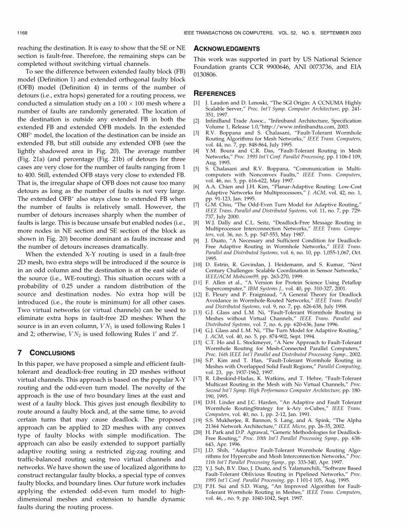
To see the difference between regular faulty blocks (FB)(orthogonal faulty blocks (OFB) (Definition 3)) and ex-tended faulty blocks (Definition 1) (extended OFB (Defini-tion 4)) in terms of the number of nonfaulty nodes includedin these blocks, we conducted a simulation study on a 100�100mesh where a number of faults are randomly generated.Fig. 16a shows the numbers of nodes covered in FBs andextended FBs for given numbers of faults. Fig. 16b showsthe numbers of nodes covered in OFBs and extended OFBsfor given numbers of faults. It is clear from the results thatboth orthogonal faulty blocks and extended orthogonalfaulty blocks enable some nonfaulty nodes from faultyblocks and extended faulty blocks, respectively. Thenumber of unsafe but enabled nodes is not significantbecause we used a random fault distribution and the faultyblocks generated tend to be small. We expect better resultsif faults are “clustered.” Also, we observe that the two-boundary-line requirement in the extended models “in-flates” the overall size of blocks. However, such inflation isnot significant when the number of faults is relatively small.
To apply the extended X-Y routing in 2D meshes withorthogonal faulty blocks, the source should be an enablednode and the destination should be a safe node that is not aboundary node of an orthogonal faulty block. In this case,an unsafe but enabled node (a node inside the extended
WU: A FAULT-TOLERANT AND DEADLOCK-FREE ROUTING PROTOCOL IN 2D MESHES BASED ON ODD-EVEN TURN MODEL 1163
Fig. 13. A localized algorithm for determining extended enabled/disabled status.
Fig. 14. The extended orthogonal faulty blocks of three extended faulty blocks in Fig. 5.
faulty block but outside the extended orthogonal faultyblock) can be a source but not a destination. Also, such anode can be used for routing like a “lamb” node in [15].
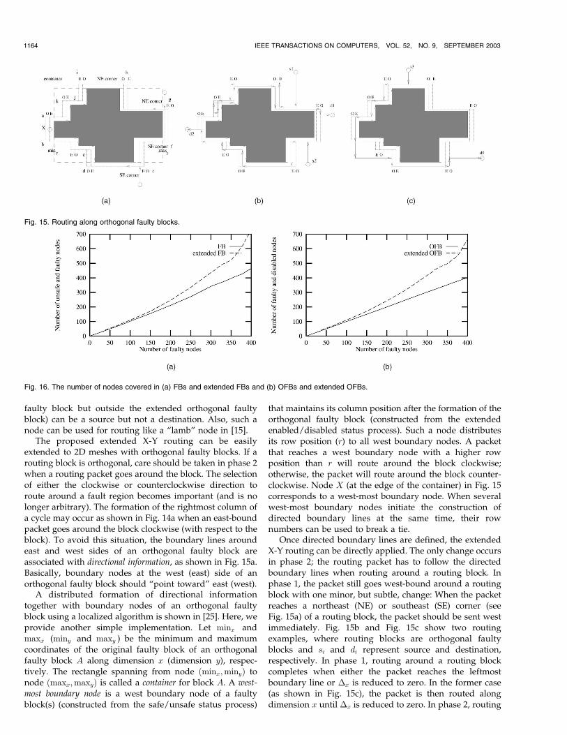
The proposed extended X-Y routing can be easilyextended to 2D meshes with orthogonal faulty blocks. If arouting block is orthogonal, care should be taken in phase 2when a routing packet goes around the block. The selectionof either the clockwise or counterclockwise direction toroute around a fault region becomes important (and is nolonger arbitrary). The formation of the rightmost column ofa cycle may occur as shown in Fig. 14a when an east-boundpacket goes around the block clockwise (with respect to theblock). To avoid this situation, the boundary lines aroundeast and west sides of an orthogonal faulty block areassociated with directional information, as shown in Fig. 15a.Basically, boundary nodes at the west (east) side of anorthogonal faulty block should “point toward” east (west).
A distributed formation of directional informationtogether with boundary nodes of an orthogonal faultyblock using a localized algorithm is shown in [25]. Here, weprovide another simple implementation. Let minx andmaxx (miny and maxy ) be the minimum and maximumcoordinates of the original faulty block of an orthogonalfaulty block A along dimension x (dimension y), respec-tively. The rectangle spanning from node ðminx;minyÞ tonode ðmaxx;maxyÞ is called a container for block A. A west-
most boundary node is a west boundary node of a faultyblock(s) (constructed from the safe/unsafe status process)
that maintains its column position after the formation of theorthogonal faulty block (constructed from the extendedenabled/disabled status process). Such a node distributesits row position (r) to all west boundary nodes. A packetthat reaches a west boundary node with a higher rowposition than r will route around the block clockwise;otherwise, the packet will route around the block counter-clockwise. Node X (at the edge of the container) in Fig. 15corresponds to a west-most boundary node. When severalwest-most boundary nodes initiate the construction ofdirected boundary lines at the same time, their rownumbers can be used to break a tie.
Once directed boundary lines are defined, the extendedX-Y routing can be directly applied. The only change occursin phase 2; the routing packet has to follow the directedboundary lines when routing around a routing block. Inphase 1, the packet still goes west-bound around a routingblock with one minor, but subtle, change: When the packetreaches a northeast (NE) or southeast (SE) corner (seeFig. 15a) of a routing block, the packet should be sent westimmediately. Fig. 15b and Fig. 15c show two routingexamples, where routing blocks are orthogonal faultyblocks and si and di represent source and destination,respectively. In phase 1, routing around a routing blockcompletes when either the packet reaches the leftmostboundary line or �x is reduced to zero. In the former case(as shown in Fig. 15c), the packet is then routed alongdimension x until �x is reduced to zero. In phase 2, routing
1164 IEEE TRANSACTIONS ON COMPUTERS, VOL. 52, NO. 9, SEPTEMBER 2003
Fig. 15. Routing along orthogonal faulty blocks.
Fig. 16. The number of nodes covered in (a) FBs and extended FBs and (b) OFBs and extended OFBs.

around a routing block completes when either the packetreaches the rightmost boundary line or �x is reduced tozero. In the former case, the packet is routed alongdimension x until �x is reduced to zero and then �y isreduced by sending the packet along dimension y. In thelatter case, the packet is routed directly along dimension yto reduce �y (as shown in the example ðs1; d1Þ of Fig. 15b).Theorem 3. Using the orthogonal faulty block model, the
modified extended X-Y routing is still deadlock-free andlivelock-free.
Proof (Sketch). In phase 1, assume that the packet is north-bound (the south-bound case can be treated in a similarway), routing around a routing block involves asequence of the following turns: NW, (WS, SW)�, (WN,NW)�, WN, where (WS, SW)� represents zero or morerepetitions of WS, SW turns (as shown in the exampleðs2; d2Þ of Fig. 15b). All sensitive turns, NW and SW,occur in even columns and they are permissible. In thetransition between phase 1 and phase 2, either an NW orNE is performed in an even column. In phase 2, assumethat the packet is east-bound (the west-bound case can betreated in a similarway), routing arounda routing block (ifany) involves a sequence of the following turns if thepacket is routed in the counterclockwise direction: ES, (SE,ES)�, SE, (EN, NE)�, EN. If the packet is routed in theclockwise direction, the following sequence of turns isused: EN, (NE, EN)�, NE, (ES, SE)�, ES. All sensitive turnsare performed in odd columns and they are permissible.Once �x is reduced to zero, either an SE or NE turn isperformed in an odd column to reduce �y. Because thedestination is outside a container, the packet is still east-bound after phase 2. Hence, the modified extended X-Yrouting is still deadlock-free and livelock-free. tu
6 EXTENSIONS
In this section, we provide some ideas for extensions, whichinclude partial adaptive routing, traffic, and adaptivity-balanced routing using virtual networks, and removingconstraints using virtual channels and networks.
6.1 Partial Adaptive Routing
The extended X-Y routing is deterministic, that is, there is
only one routing path (except when a packet routes around
a routing block). In the following, we propose a partially
adaptive routing based on the restricted zig-zag routing.
Again, routing can be divided into EW-routing (from east to
west) and WE-routing (from west to east). WE-routing
follows the extended X-Y routing which consists of phase 1
and phase 2 as discussed in the previous section (see Fig. 17a
and Fig. 17b). EW-routing follows the odd-restricted zig-zag
routing which consists of a sequence of alternating phase 1
and phase 2 (see Fig. 17c and Fig. 17d). WE-routing is still
deterministic while EW-routing is partially adaptive. The
reason thatWE-routing has to follow deterministic routing is
the following: Suppose WE-routing is allowed to use the
restricted zig-zag routing, that is, the packet can be east-
bound before phase 1 completes. If a faulty block is reached
before phase 1 completes, the packet is forced to route around
the block by goingwest. Thiswill violate the restriction of the
odd-even turnmodel: Once east-bound starts, nomore west-
bound is allowed in the routing process.Let �1
x and �1y (�2
x and �2y) be the offsets along
dimensions x and y, respectively, in phase 1 (phase 2).
The requirement at each phase is the following: In phase 1,
�1x is monotonically decreasing and, in phase 2, �2
y is
monotonically decreasing and �2x remains unchanged. It
can be easily shown that, as long as the above requirement
is met in each phase, the restricted zig-zag routing is
livelock-free. The freedom of deadlock of the restricted zig-
zag routing is obvious since all turns in both phase 1 and
phase 2 are permissible.
6.2 Traffic and Adaptivity-Balanced Routing UsingVirtual Networks
The proposed routing protocol does not make use of
resources (channels) evenly. It is obvious that even columns
are heavily used in routing in the x dimension. To balance
the channel usage, we can use two versions of the routing
protocol. One version is based on Rules 1 and 2 and heavily
uses even columns and the other one is discussed below
and heavily uses odd columns. In the second version of the
extended odd-even turn model, the rightmost column
segment of a cycle is still prevented. However, the rule of
even and odd is exchanged.
Rule 1’. Any packet is not allowed to take an EN turn at any
node located in an odd column and it is not allowed to take a
NW turn at any node located in an even column.
WU: A FAULT-TOLERANT AND DEADLOCK-FREE ROUTING PROTOCOL IN 2D MESHES BASED ON ODD-EVEN TURN MODEL 1165
Fig. 17. Partial adaptive routing: (a) and (b) extended X-Y routing for W-E routing and (c) and (d) restricted zig-zag routing for EW-routing.

Rule 2’. Any packet is not allowed to take an ES turn at any node
located in an odd column and it is not allowed to take a SW
turn at any node located in an even column.
Fig. 18 shows the permissible EN, NW, ES, and SW turns
under Rules 10 and 20in phases 1 and 2. In the second
version of the extended odd-even turn model, odd columns
are used to route the packet in the x dimension (in phase 1).
The role of even and odd is also exchanged when routing
around faulty blocks in phase 2. To support two versions of
the extended odd-even turn model, two virtual networks,
VN1 and VN2, are used. VN1 is used to enforce Rules 1 and
2 while VN2 is applied to implement Rules 10 and 20. Each
virtual network may support several virtual channels.
Fig. 19 shows the notions of virtual channels and virtual
networks using a 2� 2 mesh (Fig. 19a). Fig. 19b shows a
2� 2 mesh with two virtual channels, V C1 and V C2, but
still one network. Fig. 19c shows a 2� 2 mesh with two
virtual networks VN1 and VN2. VN1 (and VN2) consists of
virtual channels V C1s (V C2s) only.We use the configuration shown in Fig. 19c for
implementation. A virtual network is selected whenever a
packet is injected into the network. Each packet stays in the
virtual network until it reaches the destination. It is possible
to allow switching from VN1 to VN2 (see Fig. 19c) during
the routing process to increase adaptivity without causing
deadlock. We adopt the following rule for a source to select
a virtual network: VN1 is used if the destination is in an odd
column; otherwise, VN2 is chosen. The only exception is when
the source is in the 0 column. Since the 0 column does not
have a west neighbor in an odd column, VN1 is used even
though the destination may be in an even column.Note that other versions of the extended odd-even turn
model can be derived either by preventing the leftmost column
segment of a cycle or by exchanging the role of column and row.
Rules preventing the leftmost column segment of a cycle not
only provide a traffic-balanced routing to complement
Rules 1 and 2 but also provide an adaptivity-balanced
routing when used together with Rules 1 and 2. Under these
new rules, WE-routing should adopt the extended X-Y
routing while EW-routing should follow the restricted zig-
zag routing. When two versions are used together, they
provide an adaptivity-balanced routing between EW-rout-
ing and WE-routing.
6.3 Removing Constraints Using Virtual Channelsand Virtual Networks
So far, we have focused on presenting the basic idea
without going into the messy details of boundary situations.
These situations include faulty nodes at edges (or adjacent
to edges) of the 2D mesh and destinations adjacent to a
faulty block. Many existing approaches [3], [23] can be
applied to handle the former case where virtual channels
are used to route around faulty blocks at the edges of the
mesh. Note that, when the proposed approach is applied to
the 2D torus network with wraparound connections, there
will be no fault constraint at the edge of the network!
However, nodes around each dimension form a ring.
Virtual channels (or virtual networks) need to be intro-
duced to remove potential cyclic dependency.
1166 IEEE TRANSACTIONS ON COMPUTERS, VOL. 52, NO. 9, SEPTEMBER 2003
Fig. 19. (a) A 2� 2 mesh, (b) a 2� 2 mesh with two virtual channels V C1 and V C2, and (c) a 2� 2 mesh with two virtual networks VN1 and VN2.
Fig. 18. Two cases of phase 1 routing (a) and (b) and two cases of phase 2 routing (c) and (d) using Rules 10 and 20.

Here, we focus on removing condition 3 which requires
the destination not to be a boundary node of any faulty
block. In fact, the proposed algorithm works for all
destinations that are boundary nodes of faulty blocks,
except ones at the east side of a faulty block. Refer to Fig. 4c,
where an ES turn is made in an odd boundary line. If the
corresponding even boundary line is at the west of the odd
boundary line (i.e., closer to the faulty block) and the
destination is in the even boundary line, it will force an SW
turn in the odd boundary line (which is not permissible) as
the last hop. To handle this situation, two virtual channels,
V C1 and V C2, are used in those even boundary lines that
are adjacent to faulty blocks. All hops use V C1s except the
last hop which is a SW turn in the odd boundary line.Two virtual networks provide an even simpler solution.
This approach not only balances traffic but also increases
the scope of applicability, that is, the constraint that the
destination is not a boundary node of a faulty block can be
removed. Rules 1 and 2 are implemented using VN1 and it
will take care of all destinations in odd columns. In this
case, no SW or NW turn is needed at the east side of a faulty
block. Rules 10 and 20 are implemented using VN2 and it
handles all destinations in even columns. When the source
is in the 0 column and uses VN1, the packet can still be
switched to VN2 if needed when the destination is in an
even column.
The virtual channel approach can also be applied to theorthogonal faulty block model. Recall the additionalconstraint on the orthogonal faulty block model: Thedestination must be outside the container of any orthogonalfaulty block. That is, unsafe but enabled nodes (i.e., nodesinside the container but outside the orthogonal faulty block)are used only as sources or intermediate nodes to bypasstraffic, but not destinations. In fact, unsafe but enablednodes in a container ½minx : maxx;miny : maxy� form up tofour connected components. The one containing node(minx;maxy) is called SE section (see Fig. 20), the onecontaining node (minx;miny) SW section, the one contain-ing node (maxx;maxy) NE section, and the one containingnode (maxx;miny) NW section. In fact, destinations at SWand NW sections are allowed without causing any problem.The problem occurs when the packet routes around the eastside of a faulty block through a sequence of ES and SE turnsin odd columns. If the destination is inside the SE section, aSW turn in an odd column cannot be avoided (as shown inFig. 20 for a phase 2 routing). A similar situation occurswhen the packet routes around the east side of the blockthrough a sequence of EN and NE turns in odd columnsand the destination is inside the NE section. The solution isagain using two virtual channels: V C1s are used throughoutuntil an SW turn (NW turn) in an odd column is made. Inthis case, the packet enters the SE section (NE section) of thefaulty block. In the remaining steps, V C2s are used until
WU: A FAULT-TOLERANT AND DEADLOCK-FREE ROUTING PROTOCOL IN 2D MESHES BASED ON ODD-EVEN TURN MODEL 1167
Fig. 20. An SW turn in an odd column that switches from V C1 to V C2.
Fig. 21. (a) The average number of detours and (b) the ratio of average number of detours and average distance between the source and destination
nodes.
reaching the destination. It is easy to show that the SE or NEsection is fault-free. Therefore, the remaining steps can becompleted without switching virtual channels.
To see the difference between extended faulty block (FB)
model (Definition 1) and extended orthogonal faulty block(OFB) model (Definition 4) in terms of the number ofdetours (i.e., extra hops) generated for a routing process, weconducted a simulation study on a 100� 100 mesh where anumber of faults are randomly generated. The location of
the destination is outside any extended FB in both theextended FB and extended OFB models. In the extendedOBF� model, the location of the destination can be inside anextended FB, but still outside any extended OFB (see thelightly shadowed area in Fig. 20). The average number
(Fig. 21a) (and percentage (Fig. 21b) of detours for threecases are very close for the number of faults ranging from 1to 400. Still, extended OFB stays very close to extended FB.That is, the irregular shape of OFB does not cause too many
detours as long as the number of faults is not very large.The extended OFB� also stays close to extended FB whenthe number of faults is relatively small. However, thenumber of detours increases sharply when the number offaults is large. This is because unsafe but enabled nodes (i.e.,
more nodes in NE section and SE section of the block asshown in Fig. 20) become dominant as faults increase andthe number of detours increases dramatically.
When the extended X-Y routing is used in a fault-free2D mesh, two extra steps will be introduced if the source is
in an odd column and the destination is at the east side ofthe source (i.e., WE-routing). This situation occurs with aprobability of 0.25 under a random distribution of thesource and destination nodes. No extra hop will be
introduced (i.e., the route is minimum) for all other cases.Two virtual networks (or virtual channels) can be used toeliminate extra hops in fault-free 2D meshes: When thesource is in an even column, VN1 is used following Rules 1and 2; otherwise, VN2 is used following Rules 10 and 20.
7 CONCLUSIONS
In this paper, we have proposed a simple and efficient fault-tolerant and deadlock-free routing in 2D meshes withoutvirtual channels. This approach is based on the popular X-Yrouting and the odd-even turn model. The novelty of the
approach is the use of two boundary lines at the east andwest of a faulty block. This gives just enough flexibility toroute around a faulty block and, at the same time, to avoidcertain turns that may cause deadlock. The proposed
approach can be applied to 2D meshes with any convextype of faulty blocks with simple modification. Theapproach can also be easily extended to support partiallyadaptive routing using a restricted zig-zag routing andtraffic-balanced routing using two virtual channels and
networks. We have shown the use of localized algorithms toconstruct rectangular faulty blocks, a special type of convexfaulty blocks, and boundary lines. Our future work includesapplying the extended odd-even turn model to high-
dimensional meshes and extension to handle dynamicfaults during the routing process.
ACKNOWLEDGMENTS
This work was supported in part by US National ScienceFoundation grants CCR 9900646, ANI 0073736, and EIA0130806.
REFERENCES
[1] J. Laudon and D. Lenoski, “The SGI Origin: A CCNUMA HighlyScalable Server,” Proc. Int’l Symp. Computer Architecture, pp. 241-351, 1997.
[2] InfiniBand Trade Assoc., “Infiniband Architecture, SpecificationVolume 1, Release 1.0,”http://www.infinibandta.com, 2003.
[3] R.V. Boppana and S. Chalasani, “Fault-Tolerant WormholeRouting Algorithms for Mesh Networks,” IEEE Trans. Computers,vol. 44, no. 7, pp. 848-864, July 1995.
[4] Y.M. Boura and C.R. Das, “Fault-Tolerant Routing in MeshNetworks,” Proc. 1995 Int’l Conf. Parallel Processing, pp. I 106-I 109,Aug. 1995.
[5] S. Chalasani and R.V. Boppana, “Communication in Multi-computers with Nonconvex Faults,” IEEE Trans. Computers,vol. 46, no. 5, pp. 616-622, May 1997.
[6] A.A. Chien and J.H. Kim, “Planar-Adaptive Routing: Low-CostAdaptive Networks for Multiprocessors,” J. ACM, vol. 42, no. 1,pp. 91-123, Jan. 1995.
[7] G.M. Chiu, “The Odd-Even Turn Model for Adaptive Routing,”IEEE Trans. Parallel and Distributed Systems, vol. 11, no. 7, pp. 729-737, July 2000.
[8] W.J. Dally and C.L. Seitz, “Deadlock-Free Message Routing inMultiprocessor Interconnection Networks,” IEEE Trans. Compu-ters, vol. 36, no. 5, pp. 547-553, May 1987.
[9] J. Duato, “A Necessary and Sufficient Condition for Deadlock-Free Adaptive Routing in Wormhole Networks,” IEEE Trans.Parallel and Distributed Systems, vol. 6, no. 10, pp. 1,055-1,067, Oct.1995.
[10] D. Estrin, R. Govindan, J. Heidemann, and S. Kumar, “NextCentury Challenges: Scalable Coordination in Sensor Networks,”IEEE/ACM Mobicom99, pp. 263-270, 1999.
[11] F. Allen et al., “A Version for Protein Science Using PetaflopSupercomputer,” IBM Systems J., vol. 40, pp. 310-327, 2001.
[12] E. Fleury and P. Fraigniaud, “A General Theory for DeadlockAvoidance in Wormhole-Routed Networks,” IEEE Trans. Paralleland Distributed Systems, vol. 9, no. 7, pp. 626-638, July 1998.
[13] G.J. Glass and L.M. Ni, “Fault-Tolerant Wormhole Routing inMeshes without Virtual Channels,” IEEE Trans. Parallel andDistributed Systems, vol. 7, no. 6, pp. 620-636, June 1996.
[14] G.J. Glass and L.M. Ni, “The Turn Model for Adaptive Routing,”J. ACM, vol. 40, no. 5, pp. 874-902, Sept. 1994.
[15] C.T. Ho and L. Stockmeyer, “A New Approach to Fault-TolerantWormhole Routing for Mesh-Connected Parallel Computers,”Proc. 16th IEEE Int’l Parallel and Distributed Processing Symp., 2002.
[16] S.P. Kim and T. Han, “Fault-Tolerant Wormhole Routing inMeshes with Overlapped Solid Fault Regions,” Parallel Computing,vol. 23, pp. 1937-1962, 1997.
[17] R. Libeskind-Hadas, K. Watkins, and T. Hehre, “Fault-TolerantMulticast Routing in the Mesh with No Virtual Channels,” Proc.Second Int’l Symp. High Performance Computer Architecture, pp. 180-190, 1995.
[18] D.H. Linder and J.C. Harden, “An Adaptive and Fault TolerantWormhole RoutingStrategy for k-Ary n-Cubes,” IEEE Trans.Computers, vol. 40, no. 1, pp. 2-12, Jan. 1991.
[19] S.S. Mukherjee, R. Bannon, S. Lang, and A. Spink, “The Alpha21364 Network Architecture,” IEEE Micro, pp. 26-35, 2002.
[20] H. Park and D.P. Agrawal, “Generic Methodologies for Deadlock-Free Routing,” Proc. 10th Int’l Parallel Processing Symp., pp. 638-643, Apr. 1996.
[21] J.D. Shih, “Adaptive Fault-Tolerant Wormhole Routing Algo-rithms for Hypercube and Mesh Interconnection Networks,” Proc.11th Int’l Parallel Processing Symp., pp. 333-340, Apr. 1997.
[22] Y.J. Suh, B.V. Dao, J. Duato, and S. Yalamanchili, “Software BasedFault-Tolerant Oblivious Routing in Pipelined Networks,” Proc.1995 Int’l Conf. Parallel Processing, pp. I 101-I 105, Aug. 1995.
[23] P.H. Sui and S.D. Wang, “An Improved Algorithm for Fault-Tolerant Wormhole Routing in Meshes,” IEEE Trans. Computers,vol. 46, , no. 9, pp. 1040-1042, Sept. 1997.
1168 IEEE TRANSACTIONS ON COMPUTERS, VOL. 52, NO. 9, SEPTEMBER 2003

[24] D. Wang, “Minimal-Connected-Component (MCC)—A RefinedFault Block Model for Fault-Tolerant Minimal Routing in Mesh,”Proc. IASTED Int’l Conf. Parallel and Distributed Computing andSystems, pp. 95-100, Nov. 1999.
[25] J. Wu, “A Deterministic Fault-Tolerant and Deadlock-Free Rout-ing Protocol in 2-D Meshes without Virtual Channels,” TechnicalReport TR-CSE-00-26, Florida Atlantic Univ., Nov. 2000.
[26] J. Wu, “A Distributed Formation of Orthogonal Convex Polygonsin Mesh-Connected Multicomputers,” J. Parallel and DistributedComputing, vol. 62, pp. 1168-1185, 2002.
[27] J. Wu, “Reliable Unicasting in Faulty Hypercubes Using SafetyLevels,” IEEE Trans. Computers, vol. 46, no. 2, pp. 241-247, Feb.1997.
[28] J. Zhou and F. Lau, “Adaptive Fault-Tolerant Wormhole Routingin 2D Meshes,” Proc. 15th Int’l Parallel and Distributed ProcessingSymp. (IPDPS 2001), p. 56, 2001.
Jie Wu received the BS and MS degrees fromShanghai University of Science and Technology(now Shanghai University) in 1982 and 1985,respectively, and the PhD degree from FloridaAtlantic University in 1989. He is currently aprofessor in the Department of ComputerScience and Engineering, Florida Atlantic Uni-versity. He has published more than 200 papersin various journals and conference proceedings.His research interests are in the area of mobile
computing, routing protocols, fault-tolerant computing, and interconnec-tion networks. He has served on many conference committees andeditorial boards. He was a co-guest-editor of the IEEE Transactions onParallel and Distributed Systems and Journal of Parallel and DistributingComputing. He is the author of the text Distributed System Design (CRCPress). He was the recipient of the 1996-1997 and 2001-2002Researcher of the Year Award at Florida Atlantic University. He servedas an IEEE Computer Society Distinguished Visitor. He is a member ofthe ACM and a senior member of the IEEE.
. For more information on this or any computing topic, please visitour Digital Library at http://computer.org/publications/dlib.
WU: A FAULT-TOLERANT AND DEADLOCK-FREE ROUTING PROTOCOL IN 2D MESHES BASED ON ODD-EVEN TURN MODEL 1169