a fifty-nanosecond-rise-time thyratron light source
TRANSCRIPT

AEDC-TR-67-216 ARCHIVE COPY DO NOT LOAN
1 I
A FIFTY-NANOSECOND-RISE-TIME THYRATRON
LIGHT SOURCE
R. A. Belz and F. M. Shofner
University of Tennessee Space Institute
R. H. Hines
ARO, Inc.
November 1967
This document has been approved for public release and sale; its distribution is unlimited.
ARNOLD ENGINEERING DEVELOPMENT CENTER
AIR FORCE SYSTEMS COMMAND
ARNOLD AIR FORCE STATION, TENNESSEE
PROPERTY OF U. S. AIR FORCE fcnc 1.IRF--3Y

mm When U. S. Government drawings specifications, or other data arc used for any purpose other than a definitely related Government procurement operation, the Government thereby incurs no responsibility nor any obligation whatsoever, and the fact that the Government may have formulated, furnished, or in any way supplied the said drawings, specifications, or other data, is not to be regarded by implication or otherwise, or in any manner licensing the holder or any other person or corporation, or conveying any rights or permission to manufacture, use, or sell any patented invention that may in any way be related thereto.
Qualified users may obtain copies of this report from the Defense Documentation Center.
References to named commercial products in this report are not to be considered in any sense as an endorsement of the product by the UnitedStates Air Foice or the Government.

AEDCTR-67-216
A FIFTY-NANOSECOND-RISE-TIME THYRATRON
LIGHT SOURCE
R. A. Belz and F. M. Shofner
University of Tennessee Space Institute
R. H. Hines
ARO, Inc.
This document has been approved for public release and sale; its distribution is unlimited.

AEDC-TR-67-216
FOREWORD
The work reported herein was sponsored by Headquarters, Arnold Engineering Development Center (AEDC), Air Force Systems Command (AFSC), under Program 8219-07, Program Element 6240533F.
The results of research reported were obtained by ARO, Inc. (a sub- sidiary of Sverdrup & Parcel and Associates, Inc.), contract operator of AEDC, AFSC, Arnold Air Force Station, Tennessee, under Contract AF40(600)-1200, and the University of Tennessee Space Institute, Tulla- homa, Tennessee, under subcontracts 67-17-TS/OMD and 68-27-TS/OMD. R. A. Belz, principal investigator, is a research assistant at the Uni- versity of Tennessee Space Institute, and F. M. Shofner is a consult- ant from the University of Tennessee Space Institute. The research was performed from July 1, 1966, to September 1, 1967, under ARO Project No. BC5819, and the manuscript was submitted for publication on September 19, 1967.
This technical report has been reviewed and is approved.
M. K. Kingery Edward R. Feicht Research Division Colonel, USAF Directorate of Plans Director of Plans
and Technology and Technology
li

AEDC-TR-67-216
ABSTRACT
An inexpensive light source was built, using a gas thyratron tube, to evaluate and compare various photomultiplier tubes and associated circuitry. The rise time of the light pulse was found to be less than 50 nsec, thereby enabling high frequency response evaluations to be made. In addition, the pulse repetition rate is readily controllable. The characteristics of the system and the experimental results ob- tained with this source are presented.
111

AEDC-TR.67-216
CONTENTS
Page
ABSTRACT iii NOMENCLATURE vi
I. INTRODUCTION 1 II. GENERAL THYRATRON CIRCUIT OPERATION AND ■
PERFORMANCE 2. 1 Basic Thyratron Circuit 1 2. 2 Thyratron Grid Control 3
III. CIRCUIT DISADVANTAGES AND PULSED GRID OPERATION 5
IV. THE LIGHT DETECTOR 6 V. INTENSITY OF THE LIGHT 7
VI. SUMMARY AND CONCLUSIONS 8 REFERENCES 9
APPENDIX Illustrations
Figure
1. Thyratron Relaxation Oscillator 13
2. Thyratron Voltage and Current Waveforms 14
3. Deionization Effects 15
4. Light Intensity versus Anode Current 16
5. Light and Current Waveforms of the Thyratron 17
6. Current and Light Rise Time and Half-Widths as a Function of Grid Voltage 18
7. Average and Peak Current and Pulse Repetition Rate as a Function of Grid Voltage 19
8. Thyratron Peak Current and Light Half-Width as a Function of Cathode Resistance 20
9. Capacitor Effects on the Light Pulse 21
10. Pulse Repetition Frequency as a Function of Power Supply Resistance and Capacitance 22
11. Photomultiplier Bias Circuitry 23

AEDC-TR-67-216
NOMENCLATURE
Aj Area of light source
A 2 Area of light detector ° -10 A Angstrom unit, 10 m
B0 Quantity of energy radiated normally from a surface per cm^ per unit solid angle per cm of wavelength
C Thyratron circuit capacitor
Ca Photomultiplier output capacitance
G Amplification of photomultiplier tube
Ia Thyratron anode current
Ic Thyratron cathode current
I0 Peak value of current
Ipm Photomultiplier output current
In Naperian logarithm
P Optical power
Rc Thyratron cathode resistance
Rd Photomultiplier dynode bias resistance
RL Photomultiplier load resistance
Rps Power supply resistance
r Distance from A\ to A2
s Laplace operator
T Charging time of capacitor
Va Thyratron anode voltage
VJJD Thyratron breakdown voltage
Vg Thyratron grid voltage
V0 Photomultiplier output voltage
VpS Power supply voltage
W Radiant sensitivity of photomultiplier cathode
6(t) Unit impulse function
X Wavelength of light
< > Average value
vi

AEDC-TR-67-216
SECTION I INTRODUCTION
During the development of a laser velocimeter (LV) system, it was found that one of the limitations in measuring- high velocity flows was the frequency response of the photomultiplier (PM) detector. Since the frequency detected by the PM tube is a direct linear function of the flow velocity, the highest measurable flow rate depended, in part, on the cutoff frequency at the PM tube. A light source was therefore needed which could measure the bandwidth of the photodetector up to 5 MHz and provide a means of ascertaining any limitations imposed on it by the external circuitry.
The thyratron was chosen as the light source because of its sim- plicity of operation and its availability. It can be operated to produce large pulses of current. Associated with these current pulses are light pulses generated by the plasma conducting medium which have rise times of 50 nsec. Data are presented to show the correlation of the thyratron current and light intensity. The effects of the grid voltage and circuit parameters upon the operation are shown. The bandwidth limitations of the PM tube are discussed, and the equation for measur- ing light intensity is derived and applied to the thyratron data to obtain the peak light output.
SECTION II GENERAL THYRATRON CIRCUIT OPERATION AND PERFORMANCE
2.1 BASIC THYRATRON CIRCUIT
The basic physical electronic operation of the thyratron and its use as an active element of a relaxation oscillator are described in Refs. 1 and 2, respectively. Reference 3 has a good discussion on the applica- tion of the thyratron in high speed pulsing circuits.
Controllable, repetitive switching of the thyratron is obtained with a relaxation oscillator circuit schematically shown in Fig. 1. When the voltage on the capacitor reaches the breakdown value fixed by the grid voltage, the tube "fires, " and the capacitor rapidly discharges through it. When the current has fallen below the threshold value, deionization takes place, and the capacitor begins recharging to the breakdown voltage. The voltage and current waveforms are shown in Fig. 2. The cathode current is a "spike" occurring during the anode voltage drop as

AEDCTR-67-216
shown in Fig. 2a. The period of tube conduction, or avalanche, is shown more clearly in Fig. 2b.
Deionization must take place before conduction ceases so the capaci- tor can recharge. This sets an upper limit on the operating frequency of the circuit. At low pulse current amplitudes and high pulse repetition frequencies, the deionization current is noticeable (Fig. 3) as a slight increase after the cathode current has fallen below 6 ma. Because the tube is still conducting, the capacitor is unable to recharge until the deionization is complete. The corresponding delay of the capacitor voltage rise is illustrated in Fig. 3.
The light emitted by the plasma has approximately the same wave- form as the current, as will be seen, and is much more intense than the visible emission of the heater. A 5696 thyratron was used because its anode and cathode are unshielded, thus exposing the plasma arc.
The light was detected by a 931A photomultiplier tube with the out- put voltage across a 200-ohm load resistor. A dual-beam oscilloscope was used as the voltage indicator. The response time of the PM tube and oscilloscope was sufficient to resolve pulse widths that are neces- sary to indicate a measurable bandwidth of 5 MHz. The anode resistor was fixed at 200 ohms to reduce the frequency response limiting effects by the anode circuit. It must be emphasized that the measurements were made under laboratory conditions; field conditions will deteriorate the photodetector response unless caution in design is exercised. The limitations and peculiarities of PM pulse response are described in Section IV.
The relation of the peak light intensity and peak current was ob- tained by varying the grid potential at the thyratron and observing the magnitude of the peak current and photomultiplier output current. This relation was roughly linear as shown in Fig. 4. Figure 5 shows a typical waveform of the light pulse as measured by the PM tube and the current pulse of the thyratron source as measured across the cathode resistor. The light intensity has a 10- to 90-percent rise time of 50 nsec and a half-width of 160 nsec. The 10- to 90-percent rise time for the thyratron current, Ia, is seen to be 50 nsec also; the half-width is 260 nsec.
The peak intensity of the light was calculated and found to be approximately 380 w/cm2/ster of solid angle/cm of wavelength. The derivation of the formula is given in Section V. The rise time and in- tensity of light attainable with this simple circuit is quite useful for testing and calibration of photodetectors. The details of the circuit operation and performance will be considered in the following sections.

AEDOTR.67-216
2.2 THYRATRON GRID CONTROL
The amplitude, rise time, and half-width of the light pulse were found to be influenced strongly by the control grid. These parameters were found to be optimum when the breakdown voltage was large, be- cause the breakdown proceeds more rapidly and the tube is able to discharge the capacitor faster. Figure 6 shows the relation of the light and current pulse characteristics to the grid voltage. For a control grid bias between -1. 5 and 0 v there was excessive jitter in the light pulse, making measurements difficult. For bias voltages more nega- tive than -2. 5 v, the tube was held in cutoff because the voltage neces- sary to fire the tube was greater than that of the power supply used.
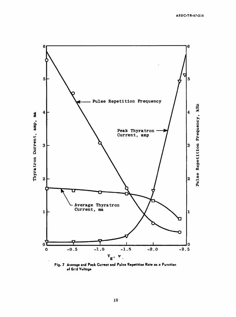
Figure 7 shows the relationship of the pulse repetition frequency to the grid voltage. The period is determined by the charging time of the capacitor to reach the breakdown voltage plus the time of deioniza- tion. The charging time is given by
T-R-CI"(CTF) (1)
where Vgrj is the breakdown voltage of the thyratron and the maintaining voltage of the thyratron has been neglected. The grid can thus control the pulse repetition frequency by varying Vßr>
Because of the low repetition frequency and short pulse width the tube operates with an average current that is less than the maximum average rating of 25 ma. This average current is approximately con- stant, decreasing as the grid voltage increases because of the lower duty cycle of the tube. However, the peak current is seen to be much larger than the maximum peak rating of 0. 1 amp for this thyratron. In spite of this excessive overrating, the lifetime of the 5696 thyratron is usually 10 hr.
The effects of the circuit parameters on the light pulse waveform were found by varying each component separately while keeping the others constant. After a component's effects on the pulse rise time, half-width, and frequency were noted, its value was fixed to produce the best pulse. The circuit values given in Fig. 1 are the result of this systematic procedure. Their effects on the pulse will be discussed in the following paragraphs. The grid voltage was set slightly below cutoff (approximately -2. 5v) for the following experiments.
The cathode resistor is used in the circuit as a current sensor. As such, its value should be less than the plasma impedance during con- duction (a few tens of ohms) so that it does not affect the discharge time
AEDCTR.67-216
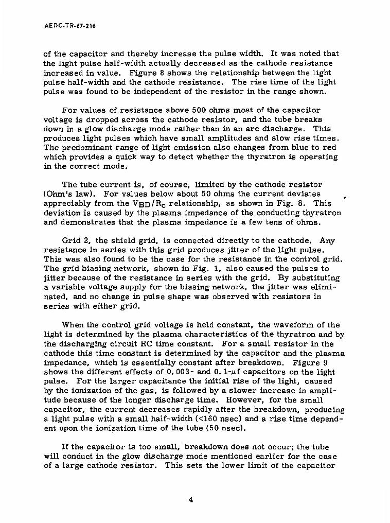
of the capacitor and thereby increase the pulse width. It was noted that the light pulse half-width actually decreased as the cathode resistance increased in value. Figure 8 shows the relationship between the light pulse half-width and the cathode resistance. The rise time of the light pulse was found to be independent of the resistor in the range shown.
For values of resistance above 500 ohms most of the capacitor voltage is dropped across the cathode resistor, and the tube breaks down in a glow discharge mode rather than in an arc discharge. This produces light pulses which have small amplitudes and slow rise times. The predominant range of light emission also changes from blue to red which provides a quick way to detect whether the thyratron is operating in the correct mode.
The tube current is, of course, limited by the cathode resistor (Ohm's law). For values below about 50 ohms the current deviates appreciably from the VBD/RC relationship, as shown in Fig. 8. This deviation is caused by the plasma impedance of the conducting thyratron and demonstrates that the plasma impedance is a few tens of ohms.
Grid 2, the shield grid, is connected directly to the cathode. Any resistance in series with this grid produces jitter of the light pulse. This was also found to be the case for the resistance in the control grid. The grid biasing network, shown in Fig. 1, also caused the pulses to jitter because of the resistance in series with the grid. By substituting a variable voltage supply for the biasing network, the jitter was elimi- nated, and no change in pulse shape was observed with resistors in series with either grid.
When the control grid voltage is held constant, the waveform of the light is determined by the plasma characteristics of the thyratron and by the discharging circuit RC time constant. For a small resistor in the cathode this time constant is determined by the capacitor and the plasma impedance, which is essentially constant after breakdown. Figure 9 shows the different effects of 0. 003- and 0. l-/uf capacitors on the light pulse. For the larger capacitance the initial rise of the light, caused by the ionization of the gas, is followed by a slower increase in ampli- tude because of the longer discharge time. However, for the small capacitor, the current decreases rapidly after the breakdown, producing a light pulse with a small half-width (<160 nsec) and a rise time depend- ent upon the ionization time of the tube (50 nsec).
If the capacitor is too small, breakdown does not occur; the tube will conduct in the glow discharge mode mentioned earlier for the case of a large cathode resistor. This sets the lower limit of the capacitor

AEDCTR-67-216
size. The 0. 003-juf capacitor is the smallest value found to operate reliably in the circuit.
The capacitor, together with the internal impedance of the power supply and the resistance, RpS. in series with it, also determines the range of pulse repetition frequencies. These parameters constitute the charging time constant of the capacitor and fix the period between pulses as given by Eq. (1). With the grid set at its maximum value be- fore cutoff, the frequency range was found to extend from 8 Hz with C = 1 /uf and Rps = 80 kilohms to 2200 Hz at C = 0. 001 juf and Rps = 20 kilohms. Figure 10 shows the frequency range for the various values of capacitance and Rps- The operating frequency of the circuit (Fig. 1) with Vg = -2. 5v is 660 Hz.
SECTION III CIRCUIT DISADVANTAGES AND PULSED GRID OPERATION
Although the free-running relaxation oscillator is able to produce bright light pulses with short rise times and narrow pulse widths, there are a few disadvantages of the circuit which must be noted. The pulse repetition frequency is controlled by the grid, but grid bias also affects the rise time of the pulse. For a light pulse with a somewhat optimum (50 nsec) rise time, the circuit must oscillate at the frequency determined by the RC time constant of the capacitor charging circuit. As was stated earlier, this time constant can be controlled by changing either the capacitance or the power supply resistor, RpS, but not over wide ranges without affecting the shape of the pulse.
To obtain a light pulse with the desired minimum rise time and minimum half-width, it was found that a peak current well over the maximum rating of the tube must be tolerated. This large current re- duces the thyratron life to approximately 10 hr of operation. The heavy ion bombardment of the cathode destroys the oxide coating causing the firing voltage to become inconsistent and the pulse frequency to jitter. Eventually the tube will cease operation.
To digress briefly, it is interesting to note a phenomenon indicating eminent failure of the thyratron. The arc will become unstable and jump from one position between the cathode and anode to another and back again, with a period of about 2 sec. The pulse frequency and ampli- tude change from maximum to minimum for each arc position with the jump occurring at the minimum. However, even while this is occurring, the thyratron light pulses continue to maintain their fast characteristics.

AEDC-TR-67-216
The frequency or timing of the light pulses can be easily controlled without changing the pulse shape by triggering the tube with a positive pulse at the control grid. With the grid biased sufficiently negative to keep the full power supply voltage below the anode firing potential, the trigger pulse will bring the tube above its cutoff voltage and initiate ionization. The repetition rate can then be controlled by simply chang- ing the grid pulse frequency. The width of the light pulses can also be increased by increasing the width of the applied pulse. When the tube is brought into conduction, by this method, the control grid accelerates electrons from, the cathode, and the plasma arc is able to develop faster, thereby decreasing the rise time of the light. Light rise times below 50 nsec have been obtained this way. This mode of operation also in- creases the useful life of the tube. A thyratron which will not fire in the free-running circuit continues to produce 50-nsec light pulses in the pulsed circuit. The jitter associated with an overworked tube is also greatly reduced for operation in the pulsed mode.
SECTION IV THE LIGHT DETECTOR
A 931-A photomultiplier tube was biased as shown in Fig. 11 to detect the light pulses. The resistor network fixes each dynode potential more positive than the preceding one so that the electrons, emitted at the cathode when a photon impinges upon it, are accelerated to the anode. Current multiplication takes place since each electron that strikes a dynode releases secondary electrons to be accelerated to the next stage. The capacitors shunting the last four stages help to stabilize the bias supply by limiting the amount of current surge from the supply caused by a current pulse.
Although the PM tube was used as the detector for the light pulse data, it was found that the output pulse width was increased by the anode circuit response. For an anode load resistance of 200 ohms and an assumed optimistic value of stray capacitance of 50 pf, the calculated PM response is 10 nsec. Calculations from the data indicate that the stray capacitance was an order of magnitude greater than assumed. Further investigation is in order.
The effect of increasing R\ is to increase the response of the tube by increasing the pulse decay time, but not the rise time. This is seen by an evaluation of the equivalent circuit for the photomultiplier tube.

AEDC-TR-67-216
The transfer impedance for this circuit is:
v0 1
'pm C (-*) <2>
For an impulse input, I06(t), the output voltage becomes
V0 = -^ exp(-t/RC) (3)
provided that RC » pulse width. Thus, the output voltage follows the initial rise of the PM tube current but decays according to the RC time constant of the load circuit.
SECTION V
INTENSITY OF THE LIGHT
Brightness, B0, is defined as the amount of energy radiated normally from a surface per unit area per unit solid angle per cm of wavelength. The total power in watts, P, received from a light source of Area, Aj_, and brightness, B0, by a detector with surface, A2, at a distance, R, away is
P = /°P(A)dA = f\ -£i B0 (A)dA (4)
where P(X) is the power per unit wavelength interval. The term A2/R is the solid angle subtended by the detector surface A2 at all points on Aj provided R » linear dimensions of A^ or A2. The terms Xj and X2 define the spectral range of the radiated power.
The radiant sensitivity W(X) of a photomultiplier cathode is defined as the number of photoemitted amperes per watt of radiation at wave- length X received by the surface. The term W(X), as indicated, is a function of the wavelength of light striking the cathode. For a PM tube the anode current is therefore
Ipm = G/"P(A)W(A)dA (5)
where G is the amplification of the PM tube. If X^ and X2 define the range of the photocathode radiant sensitivity, then either Xj or Xj, X2 or X'2 may limit the range of integration.

AEDC-TR-67-216
Combining these equations yields
Ipm = ^-»/"B0 U) W(A) dX (6)
This formula can be used to find the approximate brightness of a light source if two rather crude assumptions are made about the source and receiver. First, the radiant sensitivity W(X) at the photomultiplier is assumed to be constant between 3000A and 6000A. This average value <W(X)> is defined as
X2'
ÄTx{ WWdA
Because of the symmetry of the S-4 response curve, <W(X)> is taken to be 50 percent of W(X)max. The 931-A PM tube has S-4 cathode response with W(X)max = 0. 03 amp/w and G = 800, 000 at 1000 v bias (Ref. 4).
The second and poorest assumption is that the light emitted by the thyratron has a constant spectral distribution, i. e., continuum radia- tion. This is not the case since an electrical discharge in a low pres- sure gas produces line spectra.
Using these assumptions and solving for the brightness in the last equation yields
B = '■»' ( * ) (i\ ° G<W>A!AaAX \ cm2 • ster • cm / * ''
The brightness of the thyratron light source was measured by placing plates with holes of radii 2 mm and 2. 5 mm in front of the thyratron and PM tubes which were separated by a distance of 48 cm. The peak PM anode current of 1. 5 ma was substituted into the equation above to obtain a result of 380 w/cm^/ster/cm of wavelength.
SECTION VI SUMMARY AND CONCLUSIONS
The purpose of this project has been to develop a reliable light source capable of producing detectable pulses with short rise times. This source must be convenient to use in the field and on the bench for measuring photodetector response.
8

AEDC.TR-67-216
A 5696 thyratron tube operating in a relaxation oscillator circuit was found to accomplish this purpose. Light pulses with peak bright- ness of 380 w/cm2/ster/cm of wavelength and rise times less than 50 nsec were obtained. The relaxation oscillator circuit makes the source simple to operate and compact either in the free-running or pulsed modes.
The main inherent limitation of the circuit is the rather rapid deterioration of the thoriated tungsten cathode caused by high current pulses. Further work should be initially concentrated on determining the relative merits of a directly heated pure tungsten cathode. Work beyond this should deal with the spectral emission characteristics of the thyratron. It is expected that some lines will exhibit more rapid transient phenomena. Small high pressure arcs should also be investi- gated since the continuum emission characteristics become more pro- nounced. Because of limitations imposed by the anode circuit and/or the oscilloscope, the actual light pulse width may be substantially less than 50 nsec. However, the response achieved was adequate to satisfy the requirements set out in the introduction, and further investigation was not warranted.
REFERENCES
1. Cobine, James Dillon. Gaseous Conductors, Theory and Engineer- ing Applications. Dover Publications, Inc., New York, 1958.
2. Terman, Frederick E. Electronic and Radio Engineering, Fourth Edition, McGraw-Hill, New. York, 1955.
3. Früngel, Frank. High Speed Pulse Technology, Vol. 1, Academic Press, New York, 1965.
4. RCA Technical Manual PT-60. Phototubes and Photocells, RCA, Inc., Lancaster, Pa., 1963, p. 63.

AEDCTR-67-2U
APPENDIX
ILLUSTRATIONS
11

Bias Supply
w (3 v)
Light Out
Thyratron ^ (Type 5696)
Oscilloscope O
'.|
* Rc (15 fi)
Rps (110 K)
C (0.003 |J.f)
Note: Values shown in parentheses give performance discussed in the text.
Fig. 1 Thyratron Relaxation Oscillator
Power Supply (300 v)
n

AEDCTR-67-216
a
(200 v/div)
(3.3 amp/div)
Horizontal Scale: 0.2 msec/div
a. Entire Relaxation Waveform
(200 v/div)
(3.3 amp/div)
Horizontal Scale: 100 nsec/div
b. High Resolution of the Avalanche
Fig. 2 Thyratron Voltage and Current Waveforms
14

AEDC-TR- 67-216
Horizontal Scale: 50 M.sec/cm
Vertical Scale: I = 10 ma/div c
V = 50 v/div a
C = 0.0015 |_if
R - 110 kilohms a
V = -1.75 v S
Fig. 3 Deioniiation Effects
15

as
1UU
cd E y +J S C ID / H u 3 / u 10
/ §
•
/ >>
/ ■rt
CD C <D / C
4J
/ ■2r i »4
/
/
II II i
> m o n ■
H
■»I
0.1 1 10
Anode Peak Current, amp
Fig. 4 Light Intensity versus Anode Current
100

AEDC-TR-67-216
Horizontal Scale: 200 nsec/div
Vertical Scale: I - 133 ma/div a
I =1 ma/div pm
Fig. 5 Light and Current Waveforms of the Thyratron
17

AEDCTR.67-216
700
600
500
400
u 0) ID C
<u 6 •H H
300
200
100
V Current Half-Width
Current Rise Time
rLight Half- Width
Y Light Rise Time
-0.5 -1.0 -1.5
V v -2.0 -2.5 -3.0
Fig. 6 Current and Light Rise Time and Half-Widths as a Function of Grid Voltage
18
AEDC-TR-67-216
s
a 8 cd
■p c 9) U u
a o +->
Pi
N S3
U ß <D 3 tr
Ö o
■H ■P •H ■P V
v PS
<u m
-0.5 -1.0 -1.5 -2.0 -2.5
Fig. 7 Average and Peak Current and Pulse Repetition Rate as a Function of Grid Voltage
19

> fit o n
to O
ft 6 cd
fi a> u u o
o
cd u
EH
100 200 300 400
R , ohms c
0.16
0.14
70 O-
500
Fig. 8 Thyratron Peak Current and Light Half-Width as a Function of Cathode Resistance

AEDCTR-67-216
(1 v/div)
*
MR MR
■ | CO.003 [It)
Horizontal Scale: 0.5 |asec/cm
Fig. 9 Capacitor Effects on the Light Pulse
21

AEDCTR-67-216
10.000
N
1.000 -
u c
a 4) «
V) r-l 3 a
100
10
C =■ 0.001 nf
^..* °01 uf
g 2.5 v
300 v
_L X 10 20 30 40 50 60 70
Resistance, kilohms 80 90 100
Fig. 10 Pulse Repetition Frequency at a Function of Power Supply Resistance and Capacitance
22

AEDC-TR-67-216
(0.] |.l 1 )
(0.01 \i.r)
(0.01 |J.f)
(0.01 Hf)
R (100 K)
R (100 K)
8
R (100 K)
R (100 K)
6
R (100 K)
R (100 K)
R (100 K)
? (200 Q) o
i Anode
R (100 K)
931-A Photomultiplier Tube
Light
Cathode
(-1000 v) ps
Fig. 11 Photomultiplier Bios Circuitry
23

UNCLASSIFIED Security Classification
DOCUMENT CONTROL DATA -R&D (Security classltlcatlon of f/f/o, body of abstract and Indexing annotation must be entered when the overall report Is classified)
l. ORISINATING ACTIVITY (Corporate author)
Arnold Engineering Development Center ARO, Inc., Operating Contractor Arnold Air Force Station, Tennessee
2a. REPORT SECURITY CLASSIFICATION
UNCLASSIFIED 2b. GROUP
N/A 3. REPORT TITLE
A FIFTY-NANOSECOND-RISE-TIME THYRATRON LIGHT SOURCE
4 DESCRIPTIVE NOTES (Type at report and Inclusive dates)
Interim Report July 1, 1966 to September 1, 1967 8- AU THORISJ (First name, middle Initial, laat name)
R. A. Belz and F. M. Shofner, University of Tennessee Space Institute and R. H. Hines, ARO, Inc. 6 REPORT DATE
November 1967 7a. TOTAL NO. OF PAGES
29 7b. NO. OF REFS
Sa. CONTRACT OR GRANT NO.
AF 40(600)-1200 b. PROJECT NO.
8219 c- Program Element 6240533F
* Task 821907
Sa. ORIGINATOR'S REPORT NUMBER(S)
AEDC-TR-67-216
Be. OTHER REPORT NOISI (Any other numbers that may be aeelgned this report)
N/A 19. DISTRIBUTION STATEMENT
This document has been approved for public release and sale; its distribution is unlimited.
II. SUPPLEMENTARY NOTES
Available in DDC.
12. SPONSORING MILITARY ACTIVITY
Arnold Engineering Development Center, Air Force Systems Command, Arnold Air Force Station, Tennessee
13. ABSTRACT
An inexpensive light source was built, using a gas thyratron tube, to evaluate and compare various photomultiplier tubes and associated circuitry. The rise time of the light pulse was found to be less than 50 nsec, thereby enabling high frequency response evaluations to be made. In addition, the pulse repetition rate is readily controllable. The characteristics of the system and the experimental results ob- tained with this source are presented. (U)
DD ™?..1473 UNCLASSIFIED Security Classification

UNCLASSIFIED Security Classification
KEY WOROl
/ flight source-5
thyratrons photomultiplier
iJ?#~UtA*^
LINK C
ROLE WT
UNCLASSIFIED Security Classification